JP7521449B2 - TRANSPORT SYSTEM, TRANSPORT METHOD, AND TRANSPORT PROGRAM - Google Patents
TRANSPORT SYSTEM, TRANSPORT METHOD, AND TRANSPORT PROGRAMDownload PDFInfo
- Publication number
- JP7521449B2 JP7521449B2JP2021022733AJP2021022733AJP7521449B2JP 7521449 B2JP7521449 B2JP 7521449B2JP 2021022733 AJP2021022733 AJP 2021022733AJP 2021022733 AJP2021022733 AJP 2021022733AJP 7521449 B2JP7521449 B2JP 7521449B2
- Authority
- JP
- Japan
- Prior art keywords
- transport
- loading platform
- transport robot
- platform
- robot
- Prior art date
- Legal status (The legal status is an assumption and is not a legal conclusion. Google has not performed a legal analysis and makes no representation as to the accuracy of the status listed.)
- Active
Links
Images


Classifications
- B—PERFORMING OPERATIONS; TRANSPORTING
- B65—CONVEYING; PACKING; STORING; HANDLING THIN OR FILAMENTARY MATERIAL
- B65G—TRANSPORT OR STORAGE DEVICES, e.g. CONVEYORS FOR LOADING OR TIPPING, SHOP CONVEYOR SYSTEMS OR PNEUMATIC TUBE CONVEYORS
- B65G1/00—Storing articles, individually or in orderly arrangement, in warehouses or magazines
- B65G1/02—Storage devices
- B65G1/04—Storage devices mechanical
- B65G1/137—Storage devices mechanical with arrangements or automatic control means for selecting which articles are to be removed
- B65G1/1371—Storage devices mechanical with arrangements or automatic control means for selecting which articles are to be removed with data records
- B—PERFORMING OPERATIONS; TRANSPORTING
- B65—CONVEYING; PACKING; STORING; HANDLING THIN OR FILAMENTARY MATERIAL
- B65G—TRANSPORT OR STORAGE DEVICES, e.g. CONVEYORS FOR LOADING OR TIPPING, SHOP CONVEYOR SYSTEMS OR PNEUMATIC TUBE CONVEYORS
- B65G1/00—Storing articles, individually or in orderly arrangement, in warehouses or magazines
- B65G1/02—Storage devices
- B65G1/04—Storage devices mechanical
- B65G1/06—Storage devices mechanical with means for presenting articles for removal at predetermined position or level
- B65G1/065—Storage devices mechanical with means for presenting articles for removal at predetermined position or level with self propelled cars
- B—PERFORMING OPERATIONS; TRANSPORTING
- B65—CONVEYING; PACKING; STORING; HANDLING THIN OR FILAMENTARY MATERIAL
- B65G—TRANSPORT OR STORAGE DEVICES, e.g. CONVEYORS FOR LOADING OR TIPPING, SHOP CONVEYOR SYSTEMS OR PNEUMATIC TUBE CONVEYORS
- B65G1/00—Storing articles, individually or in orderly arrangement, in warehouses or magazines
- B65G1/02—Storage devices
- B65G1/04—Storage devices mechanical
- B65G1/137—Storage devices mechanical with arrangements or automatic control means for selecting which articles are to be removed
- B65G1/1373—Storage devices mechanical with arrangements or automatic control means for selecting which articles are to be removed for fulfilling orders in warehouses
- B—PERFORMING OPERATIONS; TRANSPORTING
- B66—HOISTING; LIFTING; HAULING
- B66F—HOISTING, LIFTING, HAULING OR PUSHING, NOT OTHERWISE PROVIDED FOR, e.g. DEVICES WHICH APPLY A LIFTING OR PUSHING FORCE DIRECTLY TO THE SURFACE OF A LOAD
- B66F9/00—Devices for lifting or lowering bulky or heavy goods for loading or unloading purposes
- B66F9/06—Devices for lifting or lowering bulky or heavy goods for loading or unloading purposes movable, with their loads, on wheels or the like, e.g. fork-lift trucks
- B66F9/063—Automatically guided
- B—PERFORMING OPERATIONS; TRANSPORTING
- B62—LAND VEHICLES FOR TRAVELLING OTHERWISE THAN ON RAILS
- B62B—HAND-PROPELLED VEHICLES, e.g. HAND CARTS OR PERAMBULATORS; SLEDGES
- B62B1/00—Hand carts having only one axis carrying one or more transport wheels; Equipment therefor
- B—PERFORMING OPERATIONS; TRANSPORTING
- B65—CONVEYING; PACKING; STORING; HANDLING THIN OR FILAMENTARY MATERIAL
- B65G—TRANSPORT OR STORAGE DEVICES, e.g. CONVEYORS FOR LOADING OR TIPPING, SHOP CONVEYOR SYSTEMS OR PNEUMATIC TUBE CONVEYORS
- B65G1/00—Storing articles, individually or in orderly arrangement, in warehouses or magazines
- B65G1/02—Storage devices
- B65G1/04—Storage devices mechanical
- B65G1/0407—Storage devices mechanical using stacker cranes
- B—PERFORMING OPERATIONS; TRANSPORTING
- B65—CONVEYING; PACKING; STORING; HANDLING THIN OR FILAMENTARY MATERIAL
- B65G—TRANSPORT OR STORAGE DEVICES, e.g. CONVEYORS FOR LOADING OR TIPPING, SHOP CONVEYOR SYSTEMS OR PNEUMATIC TUBE CONVEYORS
- B65G1/00—Storing articles, individually or in orderly arrangement, in warehouses or magazines
- B65G1/02—Storage devices
- B65G1/04—Storage devices mechanical
- B65G1/137—Storage devices mechanical with arrangements or automatic control means for selecting which articles are to be removed
- B65G1/1373—Storage devices mechanical with arrangements or automatic control means for selecting which articles are to be removed for fulfilling orders in warehouses
- B65G1/1375—Storage devices mechanical with arrangements or automatic control means for selecting which articles are to be removed for fulfilling orders in warehouses the orders being assembled on a commissioning stacker-crane or truck
Landscapes
- Engineering & Computer Science (AREA)
- Mechanical Engineering (AREA)
- Transportation (AREA)
- Structural Engineering (AREA)
- Civil Engineering (AREA)
- Life Sciences & Earth Sciences (AREA)
- Geology (AREA)
- Warehouses Or Storage Devices (AREA)
- Management, Administration, Business Operations System, And Electronic Commerce (AREA)
- Control Of Position, Course, Altitude, Or Attitude Of Moving Bodies (AREA)
Description
Translated fromJapanese本開示は、搬送システム、搬送方法、及び搬送プログラムに関する。This disclosure relates to a transport system, a transport method, and a transport program.
特許文献1は、収容装置とロボットとを有し、その連結と解除が自在である搬送システムを開示している。
特許文献1に記載された技術によると、荷物のサイズによっては収容装置に入らず、搬送することができない場合があるという問題がある。The technology described in
本開示は、このような問題を解決するためになされたものであり、搬送条件に応じた荷台部を用いて荷物を搬送する搬送システム、搬送方法、及び搬送プログラムを提供することを目的とする。The present disclosure has been made to solve such problems, and aims to provide a transport system, a transport method, and a transport program that transports luggage using a loading platform that corresponds to the transport conditions.
本実施の形態における搬送システムは、搬送ロボットと、前記搬送ロボットと連結可能な荷台部と、を有する搬送システムであって、
搬送条件に基づいて、複数種類の荷台部から、前記搬送ロボットが連結する荷台部を決定する決定手段と、
前記搬送ロボットと、前記決定手段により決定された荷台部との連結を制御する連結制御手段と、を備える。 The transport system in the present embodiment is a transport system having a transport robot and a loading platform that can be connected to the transport robot,
A determination means for determining a platform part to be connected to the transport robot from among a plurality of types of platform parts based on a transport condition;
The robot is provided with a connection control means for controlling the connection between the transport robot and the platform portion determined by the determination means.
本実施の形態における搬送方法は、搬送ロボットと、それぞれが前記搬送ロボットと連結可能な複数種類の荷台部と、を有する搬送システムにおける搬送方法であって、
搬送条件に基づいて、前記複数種類の荷台部から、前記搬送ロボットが連結する荷台部を決定する決定ステップと、
前記搬送ロボットと、前記決定ステップにより決定された荷台部との連結動作を制御する連結制御ステップと、を含む。 The transport method in the present embodiment is a transport method in a transport system having a transport robot and a plurality of types of platform units each of which can be connected to the transport robot,
a determining step of determining, based on a transport condition, a loading platform part to be coupled to the transport robot from among the plurality of types of loading platform parts;
The method includes a connection control step of controlling a connection operation between the transport robot and the platform portion determined in the determination step.
搬送ロボットと、それぞれが前記搬送ロボットと連結可能な複数種類の荷台部と、を有する搬送システムにおける搬送プログラムであって、
コンピュータに、
搬送条件に基づいて、前記複数種類の荷台部から、前記搬送ロボットが連結する荷台部を決定する決定ステップと、
前記搬送ロボットと、前記決定ステップにより決定された荷台部との連結動作を制御する連結制御ステップと、
を実行させる。 A transport program for a transport system having a transport robot and a plurality of types of platform units each of which can be connected to the transport robot, comprising:
On the computer,
a determining step of determining, based on a transport condition, a loading platform part to be coupled to the transport robot from among the plurality of types of loading platform parts;
a connection control step of controlling a connection operation between the transport robot and the platform unit determined in the determination step;
Execute the command.
本開示により、搬送条件に応じた荷台部を用いて荷物を搬送する搬送システム、搬送方法、及び搬送プログラムを提供できる。This disclosure provides a transport system, a transport method, and a transport program that transports luggage using a loading platform that meets the transport conditions.
以下、発明の実施の形態を通じて本発明を説明するが、特許請求の範囲に係る発明を以下の実施形態に限定するものではない。また、実施形態で説明する構成の全てが課題を解決するための手段として必須であるとは限らない。The present invention will be described below through embodiments of the invention, but the invention according to the claims is not limited to the following embodiments. Furthermore, not all of the configurations described in the embodiments are necessarily essential as means for solving the problem.
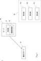
以下、図面を参照して実施形態にかかる搬送システムについて説明する。図1は、実施形態にかかる搬送システム1の構成例を示すブロック図である。図1に示す搬送システム1は、搬送ロボット10と、複数種類の荷台部20と、サーバ30とを備える。The transport system according to the embodiment will be described below with reference to the drawings. FIG. 1 is a block diagram showing an example of the configuration of a
図1では、複数種類の荷台部20として荷台部21a、荷台部21b、及び荷台部21cの3種類を示しているが、複数種類の荷台部20は、2種類であってもよく、4種類以上であってもよい。複数種類の荷台部20には、荷台部21aや荷台部21bが複数種類含まれていてもよい。以下では、荷台部21a、荷台部21b、及び荷台部21cを互いに区別しない場合には、荷台部21と称する場合がある。つまり、複数種類の荷台部20に含まれる要素は、荷台部21と称される。In FIG. 1, three types of
搬送システム1は、搬送ロボット10が、荷台部21と連結し、荷物を搬送するシステムである。搬送ロボット10は、自律移動体であり、例えば、サーバ30が生成した搬送経路に沿って自律移動を行う。尚、搬送ロボット10が自ら搬送経路を生成して自律移動を行ってもよい。したがって、サーバ30を含まないシステムも、実施形態にかかる搬送システム1には含まれ得る。The
複数種類の荷台部20は、倉庫等の配送元に設置されている。配送元には、搬送対象(例:通函)を収容するラック等の収容装置が設置されていてもよい。搬送ロボット10は、荷台部21と連結し、荷台部21に収容された物品を搬送する。Multiple types of
搬送ロボット10は、荷台部21と連結可能に構成されている。搬送ロボット10は、1つの荷台部21と連結してもよく、2つの荷台部21と連結してもよい。例えば、搬送ロボット10は、搬送ロボット10の前方と後方の両方において荷台部21と連結してもよい。尚、連結機構は、任意の構成が適用可能であり、例えば、搬送ロボット10が有するツメ部材によって、荷台部21と連結してもよい。尚、搬送ロボット10の構成については後述する。The
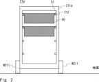
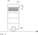
荷台部21は、搬送される荷物を収容する収容装置である。荷台部21aは、ラックとも称される。図2及び図3を用いて、荷台部21aの構成について説明する。図2及び図3は、それぞれ荷台部21aの模式正面図と模式側面図である。荷台部21aは、車輪W211と、筐体211aと、対のレール212とを備えている。一対の車輪W211は、筐体211aの下側に回転可能に固定されている。車輪W211は、従動車輪であってもよい。The
筐体211aは、例えば、天板と、底板と、右側板と、左側板と、背面板とが一体に形成された構成を有する。すなわち、筐体211aの前面は、荷物50を出し入れ可能なよう開放されている。筐体211aは、荷台部21aを自立させるための脚部(不図示)を更に備えていてもよい。The
図2及び図3に示すように、複数対のレール212は、筐体211aの内面において、奥行き方向に延設されると共に、高さ方向に等間隔に並設されている。ここで、レール212は筐体211aの内面から略垂直に立ち上がるように設けられている。図2及び図3に示すように、隣接して対向する一対のレール212上を、荷物50から幅方向外側に突出した突出部51が摺動することによって、荷物50を出し入れできる。As shown in Figures 2 and 3, the multiple pairs of
複数種類の荷台部20には、収容可能な荷物50の数が互いに異なる荷台部21aが含まれていてもよい。例えば、レール212の高さ方向の間隔が互いに等しく、筐体211aの高さが互いに異なっていてもよい。また、複数種類の荷台部20には、収容可能な荷物50のサイズが互いに異なる荷台部21aが含まれていてもよい。例えば、レール212の高さ方向の間隔が、互いに異なっていてもよい。また、筐体211aの幅や奥行き方向の長さが、互いに異なっていてもよい。The multiple types of
尚、搬送システム1には、位置が固定された収容装置が含まれていてもよい。当該収容装置は、倉庫等に設置され、配送される荷物を予め収容しておくために用いられる。当該収容装置は、上述した荷台部21aと同様に、筐体211aやレール212を備えていてもよい。The
荷台部21bは、カゴ台車とも称される。図4は、荷台部21bの構成を示す模式側面図である。荷台部21bは、車輪W211と、筐体211bとを備えている。筐体211bは、カゴ状の形態を有しており、カゴの内部に荷物50を収容することができる。筐体211bは、例えば、上面が開放されており、荷物50が投入可能に構成されていてもよい。複数種類の荷台部20には、筐体211bのサイズが互いに異なる荷台部21bが複数種類含まれていてもよい。The
また、荷台部21cは、デジタルサイネージが取り付けられた台車である。図5は、荷台部21cの構成を示す模式側面図である。荷台部21cは、車輪W211と、筐体211cとを備えている。荷台部21cは、荷台部21aと同様にレール212を備えていてもよく、荷台部21bと同様にカゴ状の形態を有していてもよい。筐体211cには、デジタルサイネージ213が取り付けられている。荷台部21cは、サーバ30の指示に応じて、デジタルサイネージ213に映像を表示させる。表示させる映像は、例えば、宣伝や広告を目的としたものであってもよい。The
荷台部21は、後述する搬送ロボット10と連結可能に構成されている。荷台部21は、例えば、図示しないツメ部材等を用いて搬送ロボット10と連結可能であってもよい。尚、搬送システム1は、荷台部21a、b、及びcの全てを備えている必要はない。The
次に、図6を参照して、搬送ロボット10の構成について説明する。図6は、搬送ロボット10の模式側面図である。搬送ロボット10は、車輪W11、本体部11、天板12、及び支柱13を備えている。2対の車輪W11は、本体部11の下側に回転可能に固定されており、モータ等の駆動源(不図示)によって駆動される。Next, the configuration of the
図6に示すように、伸縮可能な支柱13を介して天板12が本体部11に連結されている。天板12は支柱13の上端に連結されており、搬送ロボット10は、天板12に荷物50を載置して、荷物50を搬送する。As shown in FIG. 6, the
支柱13は、例えば、テレスコピック型の伸縮機構を有しており、モータ等の駆動源(不図示)によって伸縮される。図6において白抜き矢印で示すように、支柱13の長さを変更することによって、天板12の高さを変更できる。搬送ロボット10は、マニピュレータ(不図示)を用いて、倉庫等に設置された収容場所から荷物50を取り出し、複数種類の荷台部20の1つに格納することができる。The
搬送ロボット10は、支柱13の動作と、2対の車輪W11の動作と、マニピュレータ(不図示)の動作とを制御する制御部(不図示)を備えている。制御部(不図示)は、サーバ30の指示に応じて、搬送ロボット10に対して、荷台部21と連結するための動作を行わせる。The
搬送ロボット10は、荷台部21と連結するための連結機構(不図示)を備えていてもよい。例えば、搬送ロボット10は、ツメ部材等を動作させて、荷台部21と連結可能であってもよい。また、搬送ロボット10は、天板12や、マニピュレータ(不図示)を用いて、連結動作を行ってもよい。The
次に、図1に戻って、サーバ30の構成について説明する。サーバ30は、決定部31と、連結制御部32とを備えている。Next, returning to FIG. 1, the configuration of the
サーバ30は、CPU(Central Processing Unit)などの演算部と、各種制御プログラムやデータ等が格納されたRAM(Random Access Memory)、ROM(Read Only Memory)等の記憶部とを備えている。すなわち、サーバは、コンピュータとしての機能を有しており、上記各種制御プログラム等に基づいて以下の処理を行う。The
決定部31は、搬送条件に基づいて、複数種類の荷台部20から搬送ロボット10が連結する荷台部21を決定する。搬送条件は、例えば、搬送対象である荷物50の数量や、搬送対象である荷物50のサイズに関する条件である。また、搬送条件は、搬送ルートに関する条件であってもよい。更に、搬送条件は、搬送業務に付随して行われるサービスの提供にかかる条件であってもよい。例えば、搬送ロボット10は、荷台部21cのデジタルサイネージ213に広告を表示しながら荷物50の搬送を行ってもよい。決定部31は、搬送ロボット10の前方に連結する荷台部21と、搬送ロボット10の後方に連結する荷台部21の両方を決定してもよい。The
決定部31は、例えば、搬送する荷物50の数量にかかる搬送条件に基づいて、搬送ロボット10が連結する荷台部21を決定してもよい。例えば、複数種類の荷台部20に、収容可能な荷物の数量が互いに異なる荷台部21aが含まれている場合、決定部31は、搬送する荷物の数に応じて、搬送ロボット10が連結する荷台部21aを決定してもよい。具体的には、決定部31は、荷物50の数が閾値以上である場合、搬送ロボット10が連結する荷台部21を、より多くの荷物50を収容可能な荷台部21aに決定してもよい。ここで、閾値は、より小さい荷台部21aに収容される荷物の数の上限であってもよい。The
また、決定部31は、例えば、搬送する荷物50のサイズにかかる搬送条件に基づいて、搬送ロボット10が連結する荷台部21を決定してもよい。例えば、荷台部21bが収容可能な荷物50のサイズが、荷台部21aが収容可能な荷物50のサイズよりも大きい場合、決定部31は、搬送する荷物50のサイズが所定のサイズよりも大きい場合、搬送ロボット10が連結する荷台部21を、荷台部21bに決定してもよい。The
また、決定部31は、例えば、サーバ30によって生成された搬送ルート上の凹凸に応じて、搬送ロボット10が連結する荷台部21を決定してもよい。ここで、複数種類の荷台部20には、サスペンションの性能が互いに異なる荷台部21が複数種類含まれているものとする。また、決定部31は、荷物50の搬送に付随して映像の表示を行う場合、搬送ロボット10が連結する荷台部21を、デジタルサイネージ213が取り付けられた荷台部21cに決定してもよい。The
連結制御部32は、搬送ロボット10と、決定部31により決定された荷台部21と、の連結動作を制御する。連結制御部32は、決定された荷台部21の位置と、搬送ロボット10の位置とに基づいて走行ルートを生成し、搬送ロボット10に送信する。そして、搬送ロボット10は、受信した走行ルートにしたがって自律移動を行い、荷台部21との連結動作を実行する。搬送ロボット10は、例えば、ツメ部材等を用いた連結動作を行ってもよい。尚、搬送ロボット10が荷台部21の前で停止した後、人間が連結機構を操作することにより、搬送ロボット10と荷台部21とを連結させてもよい。The
ここで、上述の通り、決定部31及び連結制御部32の一部又は全部の処理は、搬送ロボット10側で行われてもよい。したがって、搬送ロボット10が、搬送条件に応じて荷台部21を決定し、決定した荷台部21に向かって走行してもよい。As described above, some or all of the processing of the
図7は、搬送ロボット10と荷台部21とが連結した状態を示す模式側面図である。図7では、搬送ロボット10の前方及び後方の両方に荷台部21が連結されているが、前方及び後方の一方のみに荷台部21が連結されてもよい。尚、上述の通り、連結機構60の構成は任意である。Figure 7 is a schematic side view showing the state in which the
図8は、実施形態にかかる搬送方法の流れを例示するフローチャートである。まず、サーバ30の決定部31が、搬送条件に基づいて、複数種類の荷台部20から、搬送ロボット10が連結する荷台部21を決定する(ステップS101)。サーバ30は、例えば、搬送する荷物50の数量や、荷物50のサイズに基づいて、搬送ロボット10が連結する荷台部21を決定してもよい。Figure 8 is a flow chart illustrating the flow of the transport method according to the embodiment. First, the
次に、サーバ30の連結制御部32は、搬送ロボット10を、ステップS101で決定された荷台部21に向かって走行させる(ステップS102)。搬送ロボット10が、ステップS101で決定された荷台部21までの移動経路を生成して、自律移動を行ってもよい。Next, the
次に、搬送ロボット10は、ステップS101で決定された荷台部21と連結する(ステップS103)。サーバ30の連結制御部32の指示に応じて、搬送ロボット10が、荷台部21と連結する動作を行ってもよい。また、人間が荷台部21と搬送ロボット10とを連結させてもよい。Next, the
次に、搬送ロボット10は、マニピュレータ(不図示)を用いて荷台部21に、搬送対象である荷物50を格納する(ステップS104)。尚、荷物50の格納は、搬送ロボット10以外のロボットや、人間によって行われてもよい。Next, the
次に、搬送ロボット10は、荷台部21と連結した状態で配送先まで走行する(ステップS105)。これにより、搬送ロボット10は、荷物50を搬送する。配送ルートは、サーバ30によって生成されてもよい。Next, the
搬送ロボット10は、配送先に到着すると、マニピュレータ(不図示)を用いて荷台部21から荷物50を取り出し(ステップS106)、配送先に設置されたラック等に格納する。搬送ロボット10は、荷台部21との連結を解除した後に、荷物50の取り出しを行ってもよい。尚、搬送ロボット10以外のロボットや、人間が、荷物50の取り出しを行ってもよい。最後に、搬送ロボット10は、倉庫等の配送元に戻る(ステップS107)。搬送ロボット10は、配送元に戻った後、荷台部21との連結を解除してもよい。尚、連結の解除は、人間が行ってもよい。When the
以下、実施形態にかかる搬送車両が奏する効果について説明する。実施形態にかかる搬送システムは、荷物の数量や、サイズ等の搬送条件に応じて適切な荷台部を選択した上で荷物を搬送することができる。The effects of the transport vehicle according to the embodiment are described below. The transport system according to the embodiment can transport luggage by selecting an appropriate loading platform according to the transport conditions such as the quantity and size of luggage.
なお、本発明は上記実施形態に限られたものではなく、趣旨を逸脱しない範囲で適宜変更することが可能である。The present invention is not limited to the above embodiment, and can be modified as appropriate without departing from the spirit and scope of the invention.
1 搬送システム
10 搬送ロボット
W11 車輪
11 本体部
12 天板
13 支柱
20 複数種類の荷台部
21、21a、21b、21c 荷台部
211a、211b、211c 筐体
212 レール
213 デジタルサイネージ
W211 車輪
30 サーバ
31 決定部
32 連結制御部
50 荷物
60 連結機構 REFERENCE SIGNS
Claims (6)
Translated fromJapanese搬送条件に基づいて、前記複数種類の荷台部から、前記搬送ロボットが連結する荷台部を決定する決定手段と、
前記搬送ロボットと、前記決定手段により決定された荷台部との連結動作を制御する連結制御手段と、
を備え、
前記複数種類の荷台部には、デジタルサイネージが取り付けられた荷台部が含まれており、
前記決定手段は、
荷物の搬送に付随して映像の表示を行う場合、前記搬送ロボットが連結する荷台部を、前記デジタルサイネージが取り付けられた荷台部に決定する、
搬送システム。 A transport system having a transport robot and a plurality of types of platform units each of which can be connected to the transport robot,
a determining means for determining a platform part to be connected to the transport robot from among the plurality of types of platform parts based on a transport condition;
a connection control means for controlling a connection operation between the transport robot and the platform portion determined by the determination means;
Equippedwith
The plurality of types of loading platform units include a loading platform unit having a digital signage attached thereto,
The determining means is
When displaying an image accompanying the transport of luggage, the loading platform part to which the transport robot is connected is determined to be the loading platform part to which the digital signage is attached.
Conveying system.
搬送対象の数にかかる前記搬送条件に基づいて、前記搬送ロボットが連結する前記荷台部を決定する、
請求項1に記載の搬送システム。 The determining means is
determining the platform unit to be connected to the transport robot based on the transport condition related to the number of transport objects;
The transport system according to claim 1 .
搬送対象のサイズにかかる前記搬送条件に基づいて、前記搬送ロボットが連結する前記荷台部を決定する、
請求項1に記載の搬送システム。 The determining means is
determining the platform part to be coupled to the transport robot based on the transport condition related to the size of the transport object;
The transport system according to claim 1 .
前記搬送ロボットの前方に連結する荷台部と、前記搬送ロボットの後方に連結する荷台部とを決定する、
請求項1から3のいずれか1項に記載の搬送システム。 The determining means is
determining a loading platform portion to be connected to a front side of the transport robot and a loading platform portion to be connected to a rear side of the transport robot;
The transport system according to any one of claims 1 to3 .
搬送条件に基づいて、前記複数種類の荷台部から、前記搬送ロボットが連結する荷台部を決定する決定ステップと、
前記搬送ロボットと、前記決定ステップにより決定された荷台部との連結動作を制御する連結制御ステップと、
を含み、
前記複数種類の荷台部には、デジタルサイネージが取り付けられた荷台部が含まれており、
前記決定ステップは、
荷物の搬送に付随して映像の表示を行う場合、前記搬送ロボットが連結する荷台部を、前記デジタルサイネージが取り付けられた荷台部に決定する、
搬送方法。 A transport method in a transport system having a transport robot and a plurality of types of platform units each of which can be connected to the transport robot, comprising:
a determining step of determining, based on a transport condition, a loading platform part to be coupled to the transport robot from among the plurality of types of loading platform parts;
a connection control step of controlling a connection operation between the transport robot and the platform unit determined in the determination step;
Including,
The plurality of types of loading platform units include a loading platform unit having a digital signage attached thereto,
The determining step includes:
When displaying an image accompanying the transport of luggage, the loading platform part to which the transport robot is connected is determined to be the loading platform part to which the digital signage is attached.
Transportation method.
コンピュータに、
搬送条件に基づいて、前記複数種類の荷台部から、前記搬送ロボットが連結する荷台部を決定する決定ステップと、
前記搬送ロボットと、前記決定ステップにより決定された荷台部との連結動作を制御する連結制御ステップと、
を実行させ、
前記複数種類の荷台部には、デジタルサイネージが取り付けられた荷台部が含まれており、
前記決定ステップは、
荷物の搬送に付随して映像の表示を行う場合、前記搬送ロボットが連結する荷台部を、前記デジタルサイネージが取り付けられた荷台部に決定する、
搬送プログラム。 A transport program for a transport system having a transport robot anda plurality of types of platform units each of which can be connected to the transport robot, comprising:
On the computer,
a determining step of determining, based on a transport condition, a loading platform part to be coupled to the transport robot from among the plurality of types of loading platform parts;
a connection control step of controlling a connection operation between the transport robot and the platform unit determined in the determination step;
Run the command,
The plurality of types of loading platform units include a loading platform unit having a digital signage attached thereto,
The determining step includes:
When displaying an image accompanying the transport of luggage, the loading platform part to which the transport robot is connected is determined to be the loading platform part to which the digital signage is attached.
Transport program.
Priority Applications (3)
| Application Number | Priority Date | Filing Date | Title |
|---|---|---|---|
| JP2021022733AJP7521449B2 (en) | 2021-02-16 | 2021-02-16 | TRANSPORT SYSTEM, TRANSPORT METHOD, AND TRANSPORT PROGRAM |
| CN202210116644.1ACN114955360A (en) | 2021-02-16 | 2022-02-07 | Transport system, transport method, and storage medium |
| US17/650,897US12286300B2 (en) | 2021-02-16 | 2022-02-14 | Transport system, transport method, and transport program |
Applications Claiming Priority (1)
| Application Number | Priority Date | Filing Date | Title |
|---|---|---|---|
| JP2021022733AJP7521449B2 (en) | 2021-02-16 | 2021-02-16 | TRANSPORT SYSTEM, TRANSPORT METHOD, AND TRANSPORT PROGRAM |
Publications (2)
| Publication Number | Publication Date |
|---|---|
| JP2022124853A JP2022124853A (en) | 2022-08-26 |
| JP7521449B2true JP7521449B2 (en) | 2024-07-24 |
Family
ID=82801990
Family Applications (1)
| Application Number | Title | Priority Date | Filing Date |
|---|---|---|---|
| JP2021022733AActiveJP7521449B2 (en) | 2021-02-16 | 2021-02-16 | TRANSPORT SYSTEM, TRANSPORT METHOD, AND TRANSPORT PROGRAM |
Country Status (3)
| Country | Link |
|---|---|
| US (1) | US12286300B2 (en) |
| JP (1) | JP7521449B2 (en) |
| CN (1) | CN114955360A (en) |
Families Citing this family (3)
| Publication number | Priority date | Publication date | Assignee | Title |
|---|---|---|---|---|
| JP7517187B2 (en)* | 2021-02-03 | 2024-07-17 | トヨタ自動車株式会社 | TRANSPORTATION SYSTEM, CONTROL METHOD, AND PROGRAM |
| JP7517194B2 (en)* | 2021-02-16 | 2024-07-17 | トヨタ自動車株式会社 | TRANSPORT SYSTEM AND TRANSPORT METHOD |
| JPWO2024116271A1 (en)* | 2022-11-29 | 2024-06-06 |
Citations (6)
| Publication number | Priority date | Publication date | Assignee | Title |
|---|---|---|---|---|
| JP2009166816A (en) | 2008-01-19 | 2009-07-30 | Will Kk | Advertisement displaying vehicle and advertising system |
| JP2011240781A (en) | 2010-05-17 | 2011-12-01 | Yaskawa Electric Corp | Automated guided vehicle and truck conveyance method |
| WO2015052825A1 (en) | 2013-10-11 | 2015-04-16 | 株式会社日立製作所 | Transfer robot system |
| JP2016182915A (en) | 2015-03-26 | 2016-10-20 | カルソニックカンセイ株式会社 | Truck connection structure |
| US20180305124A1 (en) | 2017-04-24 | 2018-10-25 | Ching Qing Guo | Automatic Batch Picking Robot |
| JP2019131403A (en) | 2019-04-04 | 2019-08-08 | 株式会社日立製作所 | Article carrier system, carrier device and article carrier method |
Family Cites Families (15)
| Publication number | Priority date | Publication date | Assignee | Title |
|---|---|---|---|---|
| JPH01176707A (en) | 1987-12-29 | 1989-07-13 | Nippon Yusoki Co Ltd | Movable rack device |
| US7894933B2 (en)* | 2005-07-19 | 2011-02-22 | Kiva Systems, Inc. | Method and system for retrieving inventory items |
| US9792577B2 (en)* | 2012-10-04 | 2017-10-17 | Amazon Technologies, Inc. | Filling an order at an inventory pier |
| US9580245B2 (en)* | 2014-06-10 | 2017-02-28 | Amazon Technologies, Inc. | Item-detecting overhead sensor for inventory system |
| US9465390B2 (en)* | 2014-11-11 | 2016-10-11 | Google Inc. | Position-controlled robotic fleet with visual handshakes |
| JP6510436B2 (en)* | 2016-02-12 | 2019-05-08 | 株式会社日立製作所 | Article conveying system, conveying apparatus and article conveying method |
| US9984339B2 (en)* | 2016-08-23 | 2018-05-29 | X Development Llc | Autonomous shuffling of pallets of items in a warehouse |
| US10395152B2 (en)* | 2016-09-16 | 2019-08-27 | Amazon Technologies, Inc. | Amassing pick and/or storage task density for inter-floor transfer |
| US10769581B1 (en)* | 2016-09-28 | 2020-09-08 | Amazon Technologies, Inc. | Overhanging item background subtraction |
| CN209275410U (en)* | 2018-11-30 | 2019-08-20 | 上海木木聚枞机器人科技有限公司 | A kind of merchandising machine people quick despatch traction commodity shelf system, traction shelf |
| CN209758194U (en)* | 2019-01-21 | 2019-12-10 | 深圳市海柔创新科技有限公司 | An intelligent storage system and combined shelves |
| US11393014B2 (en)* | 2019-05-09 | 2022-07-19 | Heb Grocery Company, Lp | Method and system for a fulfillment center and retail store fulfillment of retail orders |
| JP7308081B2 (en) | 2019-06-04 | 2023-07-13 | Thk株式会社 | Conveyor system |
| CN110606305A (en)* | 2019-07-31 | 2019-12-24 | 深圳市海柔创新科技有限公司 | An intelligent sorting system, method, storage robot and processing terminal |
| CN110980081B (en)* | 2019-12-10 | 2021-05-28 | 上海道简机电科技有限公司 | Intelligent transfer robot for warehouse logistics, transfer method and transfer system |
- 2021
- 2021-02-16JPJP2021022733Apatent/JP7521449B2/enactiveActive
- 2022
- 2022-02-07CNCN202210116644.1Apatent/CN114955360A/enactivePending
- 2022-02-14USUS17/650,897patent/US12286300B2/enactiveActive
Patent Citations (6)
| Publication number | Priority date | Publication date | Assignee | Title |
|---|---|---|---|---|
| JP2009166816A (en) | 2008-01-19 | 2009-07-30 | Will Kk | Advertisement displaying vehicle and advertising system |
| JP2011240781A (en) | 2010-05-17 | 2011-12-01 | Yaskawa Electric Corp | Automated guided vehicle and truck conveyance method |
| WO2015052825A1 (en) | 2013-10-11 | 2015-04-16 | 株式会社日立製作所 | Transfer robot system |
| JP2016182915A (en) | 2015-03-26 | 2016-10-20 | カルソニックカンセイ株式会社 | Truck connection structure |
| US20180305124A1 (en) | 2017-04-24 | 2018-10-25 | Ching Qing Guo | Automatic Batch Picking Robot |
| JP2019131403A (en) | 2019-04-04 | 2019-08-08 | 株式会社日立製作所 | Article carrier system, carrier device and article carrier method |
Also Published As
| Publication number | Publication date |
|---|---|
| US12286300B2 (en) | 2025-04-29 |
| US20220258976A1 (en) | 2022-08-18 |
| JP2022124853A (en) | 2022-08-26 |
| CN114955360A (en) | 2022-08-30 |
Similar Documents
| Publication | Publication Date | Title |
|---|---|---|
| JP7521449B2 (en) | TRANSPORT SYSTEM, TRANSPORT METHOD, AND TRANSPORT PROGRAM | |
| JP6315097B2 (en) | Picking system and picking method | |
| US10087000B2 (en) | Pallet-conveyor system | |
| ES2758753T3 (en) | Storage and order picking system and order picking procedure with independently movable shelving service appliances | |
| JP6315098B2 (en) | Sorting system and sorting method | |
| JP5880991B2 (en) | Conveying system and method for temporarily storing articles in the conveying system | |
| JP7467789B2 (en) | Item storage unit transfer system | |
| CN104903921A (en) | Supplementary retail facilities | |
| JP2007210773A (en) | Load storage processing equipment | |
| JP6822165B2 (en) | Storage equipment using a self-propelled transport trolley | |
| JP7533268B2 (en) | TRANSPORT SYSTEM AND TRANSPORT METHOD | |
| JP2022060106A (en) | Transport system and transport method | |
| TWI812727B (en) | Article transport vehicle | |
| JP2022124852A (en) | Conveying system and method | |
| JP2022124843A (en) | Conveying system and method | |
| JP2018080028A (en) | Automated warehouse | |
| JP2003343111A (en) | Mechanical parking lot and control method thereof | |
| JP2010018375A (en) | Picking facility | |
| JP6657661B2 (en) | Automatic warehouse system | |
| JP6401643B2 (en) | Parking facilities | |
| JP7250581B2 (en) | cage rack | |
| CN116710372A (en) | Conveying device, conveying system, and method for controlling conveying device | |
| JP5382452B2 (en) | Picking equipment | |
| JP2007045545A (en) | Loading and unloading device for cargo in automated warehouse | |
| JP2005272053A (en) | Commodity storage facility |
Legal Events
| Date | Code | Title | Description |
|---|---|---|---|
| A621 | Written request for application examination | Free format text:JAPANESE INTERMEDIATE CODE: A621 Effective date:20230822 | |
| A977 | Report on retrieval | Free format text:JAPANESE INTERMEDIATE CODE: A971007 Effective date:20240321 | |
| A131 | Notification of reasons for refusal | Free format text:JAPANESE INTERMEDIATE CODE: A131 Effective date:20240402 | |
| A521 | Request for written amendment filed | Free format text:JAPANESE INTERMEDIATE CODE: A523 Effective date:20240415 | |
| TRDD | Decision of grant or rejection written | ||
| A01 | Written decision to grant a patent or to grant a registration (utility model) | Free format text:JAPANESE INTERMEDIATE CODE: A01 Effective date:20240611 | |
| A61 | First payment of annual fees (during grant procedure) | Free format text:JAPANESE INTERMEDIATE CODE: A61 Effective date:20240624 | |
| R150 | Certificate of patent or registration of utility model | Ref document number:7521449 Country of ref document:JP Free format text:JAPANESE INTERMEDIATE CODE: R150 |