JP7520039B2 - Attaching an external charging probe to an electrostatic spray gun - Google Patents
Attaching an external charging probe to an electrostatic spray gunDownload PDFInfo
- Publication number
- JP7520039B2 JP7520039B2JP2021558845AJP2021558845AJP7520039B2JP 7520039 B2JP7520039 B2JP 7520039B2JP 2021558845 AJP2021558845 AJP 2021558845AJP 2021558845 AJP2021558845 AJP 2021558845AJP 7520039 B2JP7520039 B2JP 7520039B2
- Authority
- JP
- Japan
- Prior art keywords
- probe
- spray gun
- electrostatic spray
- mount
- pin
- Prior art date
- Legal status (The legal status is an assumption and is not a legal conclusion. Google has not performed a legal analysis and makes no representation as to the accuracy of the status listed.)
- Active
Links
Images


Classifications
- B—PERFORMING OPERATIONS; TRANSPORTING
- B05—SPRAYING OR ATOMISING IN GENERAL; APPLYING FLUENT MATERIALS TO SURFACES, IN GENERAL
- B05B—SPRAYING APPARATUS; ATOMISING APPARATUS; NOZZLES
- B05B5/00—Electrostatic spraying apparatus; Spraying apparatus with means for charging the spray electrically; Apparatus for spraying liquids or other fluent materials by other electric means
- B05B5/025—Discharge apparatus, e.g. electrostatic spray guns
- B05B5/03—Discharge apparatus, e.g. electrostatic spray guns characterised by the use of gas, e.g. electrostatically assisted pneumatic spraying
- B05B5/032—Discharge apparatus, e.g. electrostatic spray guns characterised by the use of gas, e.g. electrostatically assisted pneumatic spraying for spraying particulate materials
- B—PERFORMING OPERATIONS; TRANSPORTING
- B05—SPRAYING OR ATOMISING IN GENERAL; APPLYING FLUENT MATERIALS TO SURFACES, IN GENERAL
- B05B—SPRAYING APPARATUS; ATOMISING APPARATUS; NOZZLES
- B05B5/00—Electrostatic spraying apparatus; Spraying apparatus with means for charging the spray electrically; Apparatus for spraying liquids or other fluent materials by other electric means
- B05B5/025—Discharge apparatus, e.g. electrostatic spray guns
- B05B5/053—Arrangements for supplying power, e.g. charging power
- B05B5/0533—Electrodes specially adapted therefor; Arrangements of electrodes
- B05B5/0535—Electrodes specially adapted therefor; Arrangements of electrodes at least two electrodes having different potentials being held on the discharge apparatus, one of them being a charging electrode of the corona type located in the spray or close to it, and another being of the non-corona type located outside of the path for the material
Landscapes
- Electrostatic Spraying Apparatus (AREA)
Description
Translated fromJapanese(関連出願の相互参照)
本願は、A.Stech及びE.McClineによる「静電スプレーガンの外部帯電プローブ」のための、2019年4月5日出願の米国仮特許出願番号62/829,996の利益を請求する。CROSS-REFERENCE TO RELATED APPLICATIONS
This application claims the benefit of U.S. Provisional Patent Application No. 62/829,996, filed April 5, 2019, by A. Tech and E. McCline, for “External Charging Probe for Electrostatic Spray Gun.”
(技術分野)
本発明は、一般に、静電スプレーガンに関する。特に、本発明は、外部帯電プローブの静電スプレーガンへの装着に関する。(Technical field)
The present invention relates generally to electrostatic spray guns, and more particularly to mounting an external charging probe to an electrostatic spray gun.
静電スプレーガンは、一般に、接地された物体上に塗料又は粉末のような塗膜を噴霧するために使用される。静電スプレーガンは、典型的には、ガンに電荷を通し、接地された物体に向かって機械的スプレー又は圧縮空気スプレーによって噴霧される塗料又は粉末に、電荷を付与する。塗料又は粉末は、強い静電荷に起因して、接地された物体に向かって加速する。Electrostatic spray guns are commonly used to spray coatings such as paints or powders onto grounded objects. Electrostatic spray guns typically pass an electric charge through the gun, imparting a charge to the paint or powder which is sprayed by mechanical or compressed air spraying towards the grounded object. The paint or powder accelerates towards the grounded object due to the strong electrostatic charge.
一般に、静電スプレーガンは電荷を発生させるために高電圧を使用し、これはスプレーガンを通過し、かつ、外部プローブを通過することができる。静電スプレーガン及びプローブを通過する高電圧からユーザを保護し、プローブの容易かつ堅固な装着を促す静電スプレーガンを構築することが望ましい。Typically, electrostatic spray guns use high voltage to generate an electrical charge that passes through the spray gun and can pass through an external probe. It is desirable to construct an electrostatic spray gun that protects the user from the high voltage passing through the electrostatic spray gun and probe, and that facilitates easy and secure attachment of the probe.
静電スプレーガンのための装着構成は、第1の導電性要素を包み込む第1の非導電性ボディを有するプローブと、静電スプレーガンから延びると共に第2の導電性要素を包み込む第2の非導電性ボディを備えるプローブマウントと、を含む。装着構成は、第2の非導電性ボディの周りに配置されると共に第1の非導電性ボディと接触するように構成された第1のエラストマーリングを含む。第1のエラストマーリングは、プローブがホームポジションにおいて固定されるよう、第1の非導電性ボディを静電スプレーガンから離れるように付勢する力を、第1の非導電性ボディに及ぼすように構成されている。第1の非導電性ボディ及び第2の非導電性ボディのうちの一方から延びるピンが、第1の非導電性ボディ及び第2の非導電性ボディのうちの他方に形成されたノッチ内に着座する。A mounting arrangement for an electrostatic spray gun includes a probe having a first non-conductive body encasing a first conductive element, and a probe mount having a second non-conductive body extending from the electrostatic spray gun and encasing a second conductive element. The mounting arrangement includes a first elastomeric ring disposed about the second non-conductive body and configured to contact the first non-conductive body. The first elastomeric ring is configured to exert a force on the first non-conductive body biasing the first non-conductive body away from the electrostatic spray gun such that the probe is fixed in a home position. A pin extending from one of the first non-conductive body and the second non-conductive body seats in a notch formed in the other of the first non-conductive body and the second non-conductive body.
プローブを静電スプレーガンに装着する方法は、プローブを静電スプレーガン上でプローブマウントに対しスタートポジションに位置決めするステップと、プローブのピンがプローブマウントのフランジのギャップを通過するよう、プローブをプローブマウント上にかつスタートポジションへ移動させるステップと、を含む。方法は、プローブを静電スプレーガンに対して回転させるステップを含み、ピンは、プローブマウントに形成されたフランジに隣接して移動し、静電スプレーガンとフランジとの間に配置される。方法は、プローブマウントに装着され、プローブと接触し、プローブを静電スプレーガンから離れるように付勢するエラストマーリングを含み、当該エラストマーリングによって、ピンは、フランジのノッチに入ってその中に存在し、その結果、プローブはホームポジションに着座する。A method of mounting a probe to an electrostatic spray gun includes positioning the probe on the electrostatic spray gun in a start position relative to a probe mount, and moving the probe onto the probe mount and to the start position such that a pin of the probe passes through a gap in a flange of the probe mount. The method includes rotating the probe relative to the electrostatic spray gun such that the pin moves adjacent to a flange formed on the probe mount and is positioned between the electrostatic spray gun and the flange. The method includes an elastomeric ring mounted on the probe mount and contacting the probe to bias the probe away from the electrostatic spray gun, the elastomeric ring causing the pin to enter and reside within a notch in the flange such that the probe is seated in a home position.
静電スプレーガンでは、特にアセンブリの結合部において、漏電が生じる可能性がある。これらの漏電は、ユーザにとって、感電の危険を意味し得る。しかしながら、帯電プローブの取り外しのように、静電スプレーガンの耐用期間中の洗浄又は交換のために、サブパーツを取り外すことができることは、有利である。ここに開示されているのは、静電スプレーガンへの外部帯電プローブの装着構成である。開示された装着構成は、従来の静電スプレーガンと比較して、取り付け部位を通じての漏電を低減する。開示された装着構成は、更に、静電スプレーガンの作動中、プローブをホームポジションに保持する。Electrostatic spray guns can experience electrical leakage, especially at assembly joints. These leakages can represent a shock hazard to the user. However, it is advantageous to be able to remove sub-parts, such as the charging probe, for cleaning or replacement during the life of the electrostatic spray gun. Disclosed herein is a mounting arrangement for an external charging probe to an electrostatic spray gun. The disclosed mounting arrangement reduces electrical leakage through the mounting site as compared to conventional electrostatic spray guns. The disclosed mounting arrangement also holds the probe in a home position during operation of the electrostatic spray gun.
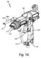
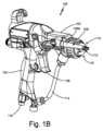
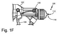
図1Aは、静電スプレーガン100の斜視図である。図1Bは、プローブ108Aを備える静電スプレーガン100の別の斜視図であり、図1Aに示された静電スプレーガン100の側とは反対側を示している。図1Cは、静電スプレーガン100に短いプローブ108Bが装着された、図1Bに示された静電スプレーガン100の斜視図である。図1Dは、プローブマウント120を示すためにプローブ108が取り外された、静電スプレーガン100の斜視図である。図1Eは、プローブマウント120を示すためにプローブ108が取り外された、静電スプレーガン100の上面図である。図1Fは、プローブマウント120を示すためにプローブ108が取り外された、静電スプレーガン100の側面図である。図1A~1Fは、一括して説明される。プローブ108A及び108Bは、一括して説明され、プローブ108と総称される。1A is a perspective view of the
図1A~1Fは、バレル102、ハンドル104、トリガ106、プローブ108、プローブ電極110、ニードル電極112、液体ライン114、空気キャップ116、空気接続部118、ニードル軸N、マウント軸M及びプローブ軸P(図2A及び2B)を含む静電スプレーガン100を示している。静電スプレーガン100は、ハンドル104及びトリガ106に取り付けられたバレル102を有する。ハンドル104は、ユーザの手の中に快適に置かれるように形成されている。バレル102は、作動中はユーザの手の上方に配置され、トリガ106は、ユーザの指によって作動され得るよう、ハンドル104の近傍にある。Figures 1A-1F show an
プローブ108は、静電スプレーガン100の作動中はバレル102に接続され、ユーザによって容易に取り外され得る。図1A及び1Bは長いプローブ108Aを示しており、図1Cは短いプローブ108Bを示している。プローブ108はプローブ電極110を含み、当該プローブ電極は、プローブマウント120とは反対側のプローブ108の端部に位置している。プローブ軸Pは、マウント軸Mに対して横方向である。いくつかの例では、プローブ軸Pはマウント軸Mに対して直角である。いくつかの実施形態では、プローブ108は2つの位置、スタートポジション及びホームポジションを有することができる。いくつかの実施形態では、プローブ108は2つより多くの位置を有することができる。The
図1A~1Cは、ホームポジションにあるプローブ108を示している。バレル102は、ハンドル104とは反対側の端部に取り付けられたニードル電極112を含んでいる。ニードル電極112は、静電スプレーガン100のニードル軸N(図1Eに示されている)に沿って延びている。図1A及び1Bは、プローブ108Aが、マウント軸M(図1Eに示されている)から離れるようにニードル軸Nに沿って軸方向に、ニードル電極112を越えて延びていることを示している。プローブ108Aは、当該プローブ108Aのプローブ電極110がニードル電極112の遠位端を越えて軸方向に延びているという点で、長いプローブである。図1Cは、プローブ108Bが、マウント軸Mから離れるようにニードル軸Nに沿って軸方向に、ニードル電極112よりも小さく延びていることを示している。プローブ108Bは、当該プローブ108Bのプローブ電極110がニードル電極112の遠位端部を越えて延びていないという点で、短いプローブである。図示された例では、プローブ108Bは、空気キャップ116を含むスプレーガン100の部分と軸方向にオーバーラップしている。プローブ108は、電界を生成するために、図1A~1Cに示されたプローブ108A及び108B以外の長さであってもよいことが理解される。プローブ108は、ニードル電極112の周囲で、かつ、プローブ電極110とニードル電極112との間の、流体出口の近傍に、電界を生成する。生成された電界は、当該電界を通過する分子をイオン化する。プローブ長は、例えば、電界を通過する分子のイオン化効率、及び、電極上への分子の堆積速度の低下のような要因に基づいて、最適化され得る。例えば、噴霧された材料が空気キャップから出ると、より長いプローブは噴霧領域内に延びる可能性があり、これによりユーザは、プローブ電極をより頻繁に停止し洗浄することが求められる。1A-1C show the
液体ライン114はハンドル104及びバレル102に取り付けられており、液体リザーバ(図1A~1Cには示されていない)から、ニードル電極112が貫通して延びる空気キャップ116へ、液体を送給するように構成されている。液体は、例えば水性塗料のような、電界中でイオン化し得る任意の液体であってよい。空気接続部118は、ハンドル104に取り付けられており、例えば空気圧縮機又は圧縮空気タンクのような空気リザーバ(図1A~1Cには示されていない)から、ハンドル104及びバレル102を通って空気キャップ116へ、空気を送給する。A
作動上、静電スプレーガン100は、プローブ108がホームポジションにあるとき、プローブ電極110とニードル電極112との間に、電界を生成することができる。静電スプレーガンは、プローブがホームポジションから不用意にノックされた場合でも、なお電界を生成することができるが、開示された装着構成は、有利には、静電スプレーガンの作動中にプローブをホームポジションに保持することに貢献する。生成された電界は、塗料分子を含む分子が電界を通過する際、当該分子をイオン化する。液体ライン114からの液体は、2つの流体が空気キャップ116から噴出される際、空気接続部118からの空気と混合される。空気は、電界を通過する分子をイオン化する、生成された電界を通って液体が加速される際、液体を成形し、帯電した流体噴霧を生成する。イオン化された分子は、接地された基板に向かって引き寄せられる。In operation, the
バレル102及びプローブ108は、例えば非導電性ポリマーのような、任意の非導電性材料で形成され得る。バレル102及びプローブ108は、同じ材料又は異なる材料で形成され得る。非導電性材料は、使用中に静電スプレーガンを通過する電流から、ユーザを保護することに貢献する。例えば耐久性、非導電性、重量、コスト及びユーザへの快適性のような考慮事項が、バレル102及びプローブ108の各材料の組成を最適化するために使用され得る。The
図2Aは、プローブ108Aが装着された静電スプレーガン100の上面断面図である。図2Bは、プローブ108Bが装着された静電スプレーガン100の上面断面図である。図2A及び2Bは、一括して説明される。図2A及び2Bは、静電スプレーガン100、バレル102、プローブ108、プローブ電極110、ニードル電極112、空気キャップ116、プローブマウント120、凹部122、突起123、スプリング124、キャビティ125、電線126、ピン128、導電性ボール130、クラウン131、抵抗線132、電源134、フランジ136、ニードル軸N、マウント軸M及びプローブ軸Pを示している。Figure 2A is a top cross-sectional view of the
プローブ108は、静電スプレーガン100の作動中はバレル102に接続され、ユーザによって容易に取り外され得る。図2Aはプローブ108Aを示しており、図2Bはプローブ108Bを示している。プローブ108は、マウント軸Mとは反対側の端部に位置するプローブ電極110を含む。プローブ108は、取り付け開始時のスタートポジションと、作動中のホームポジションとの2つの位置を有する。図2A及び2Bは、ホームポジションにあるプローブ108を示している。バレル102は、ニードル軸Nに沿ってハンドル104とは反対側の端部に取り付けられたニードル電極112を含む(図1A~1F)。空気キャップ116はバレル102の端部に配置されており、ニードル電極112は、ニードル軸Nに沿って、かつ、空気キャップ116の中心開口を通って、延びている。空気キャップ116は、液体及び空気の両方の出口を有し、それらは、液体及び空気が空気キャップ116を出る際に液体を混合し霧化するよう、液体及び空気を導く。プローブ108は、電界を生成し、当該電界を通過する分子をイオン化するために、図2A及び2Bに示されたもの以外の長さであり得ることが理解される。プローブ長は、例えば、電界を通過する分子のイオン化効率、及び、電極上への分子の堆積速度のような要因に基づいて、最適化され得る。The
プローブ108は、プローブマウント120を受容するように構成された凹部122を有する。凹部122は、円形の突起123を含み、当該突起は、実質的に凹部122の中心からバレル102に向かってマウント軸Mに沿って軸方向に内側へ延びている。スプリング124は、円形の突起123の実質的に中心に位置するキャビティ125内に配置されている。スプリング124は電線126に取り付けられており、当該電線は、プローブ電極110まで延び、これに接続している。ピン128は、静電スプレーガン100の作動中にプローブ108をホームポジションに固定するために、ノッチ138(図4Bに最も良好に見られる)と適合するように構成されている。スプリング124は、静電スプレーガン100の作動中にピン128をノッチ138内に固定すべく、プローブ108をプローブマウント120から押し離すような力を加えることができる。一実施形態では、図2A及び2Bに示されているように、ピン128はプローブ108に取り付けられ、凹部122内に延びている。ピン128は、プローブ軸Pに沿って、プローブ電極110とは反対側のプローブ上に位置している。一実施形態では、ピン128はプローブマウント120に取り付けられている。ピン128は、凹部122内に延び、静電スプレーガン100の作動中にプローブ108をプローブマウント120上に保持することに貢献する。一実施形態では、ピン128はプローブ108又はプローブマウント120から取り外し可能であり、新しいピンと交換され得る。例えば、ピン128は、他の選択肢の中でもネジ付きインターフェースによって、プローブ108及びプローブマウント120のうちの一方に接続され得る。ピン128には時間の経過と共に磨耗が生じる可能性があり、プローブ108又はプローブマウント120のようなより大きな部品ではなく、ピン128のみを交換できることは、ユーザにかなりのコスト削減をもたらす。The
プローブマウント120は、バレル102に接続され、マウント軸Mに沿って軸方向にバレル102の縁部を越えて延びている。プローブマウント120は、例えば、他の選択肢の中でもインターフェース付きネジ切り、圧入又は接着剤のような任意の所望の方法で、バレル102に接続され得る。いくつかの例では、プローブマウント120は、例えばインターフェース付きネジ切りによって、取り外し可能にバレル102に接続されている。導電性ボール130が、プローブマウント120のクラウン131の内側に、かつ、マウント軸Mに沿ってバレル102とは軸方向において反対側に位置するプローブマウント120の端部に、配置されている。導電性ボール130は、抵抗線132の第1の端部に取り付けられており、電源134が、抵抗線132の第2の端部に電気的に接続されている。作動上、静電スプレーガン100は、プローブ108がホームポジションにあるとき、プローブ電極110とニードル電極112との間に、電界を生成することができる。電源134は、抵抗線132、導電性ボール130、スプリング124及び電線126を通じてプローブ電極110に電流を供給する。プローブマウント120が、バレル102から延びプローブ108によって受容されるものとして説明されたが、いくつかの例では、プローブマウント120が、プローブ108から延びバレル102によって受容され得ることが理解される。スプリング124及び第1のエラストマーリング140とのものを含む、プローブマウント120とプローブ108との間の電気的及び機械的インターフェースは、バレル102の内部で、バレル102及び/又はバレル102内の構成要素と、バレル102内に延びバレル102によって受容されるプローブ108及び/又はプローブマウント120の一部との間に、形成され得る。例えば、プローブマウント120は、プローブ108に固定され得るか、又は、バレル102内に受容されるようプローブ108と一体の部品として形成され得る。The
生成された電界は、例えば塗料分子を含み得る分子が電界を通過する際、当該分子をイオン化する。液体及び空気は、空気キャップ116から放出される。混合された液体及び空気は、通過する分子をイオン化する、生成された電界によって加速される。イオン化された分子は、接地された基板に向かって引き寄せられる。The generated electric field ionizes molecules, which may include, for example, paint molecules, as they pass through the field. The liquid and air are expelled from the
図3Aは、第1の装着状態にあるプローブ108を示す拡大断面図である。図3Bは、第2の装着状態にあるプローブ108を示す拡大断面図である。図3A及び3Bは、一括して説明される。図3A及び3Bは、プローブ108、プローブボディ109、バレル102、プローブマウント120、プローブマウントボディ121、凹部122、円形の突起123、スプリング124、キャビティ125、電線126、ピン128、ピンスロット129、導電性ボール130、クラウン131、抵抗線132、フランジ136、フランジ137、ノッチ138、第1のエラストマーリング140、動的溝142、第2のエラストマーリング144、静的溝146、並びに、肩部148,150,152、動的溝第1端部154及び動的溝第2端部156を示している。Figure 3A is an enlarged cross-sectional view of the
プローブ108は、静電スプレーガン100の作動中はプローブマウント120に取り付けられるように構成されており、ユーザによって容易に取り外され得る。プローブマウント120は、機械的にも電気的にも、プローブ108を静電スプレーガン100に接続する。プローブ108は、プローブマウント120を受容するように構成された凹部122を有する。凹部122は、円形の突起123を含み、当該突起は、実質的に凹部122の中心からバレル102に向かってマウント軸Mに沿って軸方向に内側へ延びている。スプリング124は、円形の突起123の実質的に中心に位置するキャビティ125内に配置されている。スプリング124は電線126に取り付けられており、当該電線は、プローブ電極110まで延び、これに接続している。プローブ108のプローブボディ109は非導電性であり、スプリング124、電線126及びプローブ電極110の一部のようなプローブ108の導電性要素を包み込んでいる。プローブマウント120は、バレル102に接続され、マウント軸Mに沿って軸方向にバレル102の縁部を越えて延びている。プローブマウント120は、例えばインターフェース付きネジ切りのような任意の所望の方法で、バレル102に取り外し可能に接続され得る。The
ピン128は、プローブ108がホームポジションにある状態で、プローブ108をプローブマウント120に固定するように構成されている。図示された例では、ピン128はプローブ108のプローブボディ109に取り付けられており、プローブボディ109を通って凹部122の内部へ延びている。図示された例では、ピン128は、プローブマウント120に装着されたプローブ108がホームポジションにある状態で、プローブマウント120がプローブ軸Pに沿う軸方向においてピン128とプローブ電極110との間に位置するように、配置されている。いくつかの実施形態では、ピン128は、プローブマウント120のプローブマウントボディ121に取り付けられ、そこから突出する。ピン128は、凹部122内に突出し、静電スプレーガン100の作動中にプローブ108をプローブマウント120上でホームポジションに保持する。いくつかの実施形態では、ピン128はプローブ108又はプローブマウント120から取り外し可能であり、新しいピン128と交換され得る。例えば、ピン128は、他の選択肢の中でもインターフェース付きネジ切りによって、プローブ108又はプローブマウント120に接続され得る。ピン128には時間の経過と共に磨耗が生じる可能性があり、プローブ108又はプローブマウント120のようなより大きな部品ではなく、ピン128のみを交換することができることは、ユーザにとってかなりのコスト削減という結果をもたらし得る。The
導電性ボール130が、プローブマウント120の、マウント軸Mに沿う軸方向においてバレル102に接続された端部とは反対側の端部で、プローブマウント120のクラウン131の内側に配置されている。導電性ボール130は、プローブマウント120のプローブマウントボディ121を通って軸方向に延びる抵抗線132の第1の端部に取り付けられており、電源が、抵抗線132の第2の端部に電気的に接続されている。換言すれば、非導電性であるプローブマウントボディ121が、導電性ボール130及び抵抗線132のような導電性要素を包み込んでいる。一実施形態では、プローブマウント120は、当該プローブマウント120のプローブマウントボディ121から径方向に突出するフランジ136を含む。フランジ136は、プローブマウント120のプローブマウントボディ121の周りで部分的に延びている。フランジ136は、ピン128を受容するように構成されたノッチ138を有する。図3Aは、ノッチ138に隣接するピン128を示している。図3Bは、ノッチ138内に配置されたピン128を示しており、これはホームポジションと呼ぶことができる。A
第1のエラストマーリング140は、プローブマウント120のプローブマウントボディ121に形成された動的溝142内に存在する。動的溝142は、プローブマウント120のクラウン131に隣接して配置されており、第1の端部154及び第2の端部156(図4A~4Cに示されている)を有する。動的溝第1端部154は、動的溝第2端部156と比較して、より小さい直径を有する。動的溝142の直径は、第1端部154と第2端部156との間で滑らかに変化する。第1のエラストマーリング140は、非導電性の弾性材料で形成されている。いくつかの実施形態では、第1のエラストマーリング140はOリングであり得る。動的溝142は、プローブ108がプローブマウント120に取り付けられた際、第1のエラストマーリング140が伸びて当該リング140の直径を増大させ得るように成形されている。第1のエラストマーリング140は、静電スプレーガン100の作動中に、プローブ108がホームポジションにある状態で、ピン128をノッチ138内に着座させる弾性力を提供する。スプリング124及び第1のエラストマーリング140は、静電スプレーガン100の作動中に、ピン128をノッチ138内に着座させ固定するための力を提供すべく、協働することができる。第2のエラストマーリング144は、バレル102に隣接して配置された静的溝146内に存在する。第2のエラストマーリング144は、非導電性の弾性材料で形成されている。いくつかの実施形態では、第2のエラストマーリング144はOリングであり得る。The first
プローブボディ109は、肩部148、150及び152を含む。肩部148は、第1のエラストマーリング140に隣接して配置されている。肩部148は第1のエラストマーリング140と接触し、装着プロセス中に、第1のエラストマーリング140を動的溝142に沿って下方へ、バレル102に向かって押すように構成されている。肩部150は、肩部148に隣接して配置されており、装着プロセス中に、第1のエラストマーリング140が動的溝142から押し出されることを防止する。肩部152は第2のエラストマーリング144と接触し、プローブ108がプローブマウント120上に更に容易に押し付けられないように、ストッパを提供することができる。The
装着の間、プローブ108は、プローブマウント120の上方に配置され、プローブマウント120に対して、バレル102に向かって移動される。肩部148は第1のエラストマーリング140と係合し、第1のエラストマーリング140を、動的溝第1端部154から、動的溝142に沿って、動的溝142の動的溝第2端部156に向かって移動させる。したがって、第1のエラストマーリング140は、図3Bに示された位置から図3Aに示された位置へ移動される。ピン128は、フランジ136のギャップ158(図4Cに示されている)を通過し、凹部122内に入る。次いで、プローブ108は、プローブマウント120の周りで、図3Aに示された位置まで回転される。より詳細に後述するように、ピン128は、プローブ108が回転するにつれて、バレル102に対向するフランジ136の側面、及び、クラウン131に対向するフランジ137の側面と接触する。バレル102に対向するフランジ136の側面と、クラウン131に対向するフランジ137の側面は、共にピンスロット129を画定する。プローブ108が図3Aに示された位置に到達すると、第1のエラストマーリング140によってプローブ108に加えられた力が、プローブ108をバレル102から離れるように押し、第1のエラストマーリング140が、動的溝142に沿って移動して図3Bに示された位置に戻る。プローブ108をバレル102から離れるように付勢する第1のエラストマーリング140によって、ピン128はノッチ138内に入り着座する。ノッチ138内に着座するピン128、及び、プローブ108をバレル102から離れるように付勢すると共にピン128をノッチ138内に保持する第1のエラストマーリング140が、ホームポジションでプローブ108をプローブマウント120に固定する。During installation, the
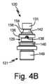
図4Aは、プローブマウント120の斜視図である。図4Bは、プローブマウント120の背面図であり、ノッチ138を備えるフランジ136を示している。図4Cは、プローブマウント120の正面図であり、ギャップ158を備えるフランジ136を示している。図4A~4Cは、一括して説明される。図4A~4Cは、プローブマウントボディ121、ピンスロット129、クラウン131、フランジ136、フランジ137、ノッチ138、動的溝142、静的溝146、ギャップ158、装着端部149、動的溝第1端部154、動的溝第2端部156及びギャップ158を含む、プローブマウント120を示している。Figure 4A is a perspective view of the
動的溝142は、第1端部154及び第2端部156を有する。動的溝第1端部154は、動的溝第2端部156と比較して、より小さい直径を有する。動的溝142の直径は、第1端部154と第2端部156との間で滑らかに変化する。いくつかの実施形態において、第1端部154と第2端部156との間の動的溝142の形状は直線状である。いくつかの実施形態において、第1端部154と第2端部156との間の動的溝142の形状は、曲線のような非直線状である。The
フランジ136は、プローブマウントボディ121から略径方向に突出し、動的溝142と静的溝146との間に配置されている。フランジ136はピン128がフランジ136を通過し、フランジ136と下部フランジ137との間に画定されたピンスロット129内に入ることを可能とするためのギャップ158を有する。ノッチ138は、フランジ136の下面に形成されており、プローブ108(図1A~1Cに最も良好に見られる)をホームポジションに維持するためにピン128(図3A及び3Bに最も良好に見られる)を受容するように構成されている。図示された例では、ノッチ138は、プローブマウントボディ121のギャップ158とは反対側に配置されている。プローブマウントボディ121のギャップ158とは反対側にノッチ138が配置されていることにより、プローブ108がノックされホームポジションから外れた場合であっても、作動中に静電スプレーガン100からプローブ108が不用意に分離されることが防止される。The
図4A~4Cに示されているように、プローブマウント120は、プローブマウント120の装着端部149とは反対側の端部に配置されたクラウン131を含むことができる。プローブマウントボディ121に沿って軸方向に移動すると、プローブマウント120は、クラウン131、動的溝142、フランジ136、ピンスロット129、下部フランジ137、静的溝146及び装着端部149を含む。As shown in Figures 4A-4C, the
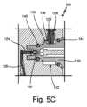
図5Aは、スタートポジションの近傍にあるプローブ108の断面図である。図5Bは、スタートポジションとホームポジションの中間にあるプローブ108の断面図である。図5Cは、ホームポジションにあるプローブ108の断面図である。図6Aは、静電スプレーガン100に対してスタートポジションにあるプローブ108を示す部分等角図である。図6Bは、スタートポジションとホームポジションの中間にあるプローブ108を示す部分等角図である。FIG. 5A is a cross-sectional view of the
図6Cは、ホームポジションにあるプローブ108を示す部分等角図である。図5A~5C及び6A~6Cは、一括して説明される。図5A~5C及び6A~6Cも、バレル102、プローブ108、プローブマウント120、凹部122、スプリング124、電線126、ピン128、導電性ボール130、フランジ136、ノッチ138、第1のエラストマーリング140及び第2のエラストマーリング144を含む静電スプレーガン100を示している。Figure 6C is a partial isometric view showing the
図5A~5C及び6A~6Cは、スタートポジション210から中間位置220へ及びホームポジション230へ、プローブ108をプローブマウント120に装着するプロセスを示している。静電スプレーガン100のバレル102へのプローブ108の装着は、図5A及び6Aに示されているように、プローブ108がスタートポジションに配置された位置210にプローブがある状態で始まる。図5Aに示されているように、ピン128がギャップ158を通ってピンスロット129内に移動するまで、プローブ108はプローブマウント120上に押し付けられる。ピンスロット129内にピン128が配置された状態で、プローブがプローブマウント120の周りで回転される。Figures 5A-5C and 6A-6C show the process of mounting the
プローブ108は、スタートポジション210から中間位置220を通ってホームポジション230へ回転される。図5B及び6Bは、スタートポジション210とホームポジション230との間の中間位置220にあるプローブ108を示している。プローブ108がスタートポジション210とホームポジション230との間を移動するにつれて、フランジ136はピン128と係合し、プローブ108がプローブマウント120から外れることが防止される。プローブ108が中間位置にある状態でフランジ136と接触するピン128によって、プローブ108が不用意にプローブマウント120から外れることが防止される。これはまた、ユーザが不用意にプローブ108をホームポジション230からノックする可能性があるため、作動中に利点を提供する。プローブ108はプローブマウント120から脱落せず、代わりにプローブマウント120上に留まり、ユーザは、単にプローブ108を回転させてホームポジションに戻し、操作を再開することができる。The
肩部148は、第1のエラストマーリング140を動的溝142に沿って押し、これにより第1のエラストマーリング140が動的溝142に沿って下方に移動し、プローブ108を静電スプレーガン100から離れるように付勢する力を第1のエラストマーリング140がプローブ108に及ぼすよう、第1のエラストマーリング140の直径が拡大する。スプリング124は、プローブ108がプローブ108上に押し付けられるにつれて圧縮され、これはまた、プローブ108を静電スプレーガン100から離れるように付勢する力を発生させる。図5C及び6Cに示されているように、プローブ108はホームポジション230へ回転される。プローブ108がホームポジションにある状態で、第1のエラストマーリング140によって及ぼされる付勢力によって、ピン128がノッチ138内に入る。プローブ108がホームポジションにある状態で、第1のエラストマーリング140は、プローブ108に付勢力を及ぼし続ける。スプリング124と共に第1のエラストマーリング140によって加えられる力、及び、ピン128とノッチ138との間の接触によって、作動中にプローブ108はホームポジションに固定される。プローブ108は、プローブ108をホームポジション230からスタートポジション210に回転させ、次いで、プローブ108をプローブマウント120に沿ってバレル102から引き離すだけで、ガン100から取り外すことができる。いくつかの実施形態では、プローブ108は、スタートポジションからホームポジションまで、マウント軸Mの周りで180°回転される。いくつかの実施形態では、プローブ108は、スタートポジションからホームポジションまで、マウント軸Mの周りで180°より小さく回転される。いくつかの実施形態では、プローブ108は、スタートポジションからホームポジションまで、マウント軸Mの周りで180°より大きく回転される。The
図7は、プローブ108がホームポジションにあるときのピン128及びノッチ138の一実施形態を示している。図7は、クラウン131、フランジ136、ノッチ138、第1のエラストマーリング140及び動的溝142を含むプローブマウント120を示している。図7に示されているように、ピン128は、当該ピン128がノッチ138を画定する表面全体と接触しないように、部分的にノッチ138内に位置することができる。図示された例では、ピン128及びノッチ138は2つの接触点を有する。ピン128が部分的にノッチ138内に着座し、個別の接触点を含むことにより、ピン128上及びノッチ138上の摩耗が減少し、ピン128及びノッチ138の耐用年数が増加する。いくつかの例では、ピン128が完全にノッチ138内に着座し得ることが理解される。Figure 7 shows one embodiment of the
静電スプレーガンでは、特にアセンブリの結合部において、漏電が生じる可能性がある。これらの漏電は、ユーザにとって、感電の危険を意味し得る。しかしながら、静電スプレーガンの耐用期間中の洗浄又は交換のために、帯電プローブのようなサブパーツを取り外すことができることは、有利である。説明された装着構成は、従来の静電スプレーガンと比較して、取り付け部位を通じての漏電を低減する。加えて、装着構成は、静電スプレーガンの作動中、プローブ108をホームポジションに保持する。Electrostatic spray guns can experience electrical leakage, especially at assembly joints. These leakage currents can represent a shock hazard to the user. However, it is advantageous to be able to remove subparts, such as the charged probe, for cleaning or replacement during the life of the electrostatic spray gun. The described mounting arrangement reduces electrical leakage through the mounting site compared to conventional electrostatic spray guns. In addition, the mounting arrangement holds the
例示的な実施形態を参照して本発明を説明してきたが、本発明の範囲から逸脱することなく、様々な変更を行うことができ、その要素の代わりに均等物を用いることができることが、当業者には理解されよう。加えて、その本質的な範囲から逸脱することなく、特定の状況又は材料を本発明の教示に対して適合させるために、多くの修正を行うことができる。Although the invention has been described with reference to illustrative embodiments, those skilled in the art will recognize that various modifications may be made and equivalents may be substituted for elements without departing from the scope of the invention. In addition, many modifications may be made to adapt a particular situation or material to the teachings of the invention without departing from essential scope thereof.
したがって、本発明は、開示された特定の実施形態に限定されるのではなく、添付の特許請求の範囲に含まれる全ての実施形態を含むことが、意図されている。Therefore, it is intended that the invention not be limited to the particular embodiments disclosed, but rather to include all embodiments falling within the scope of the appended claims.
Claims (13)
Translated fromJapanese第1の導電性要素を包み込む第1の非導電性ボディを有するプローブと、
前記静電スプレーガンから延びると共に第2の導電性要素を包み込む第2の非導電性ボディを含むプローブマウントと、
前記第2の非導電性ボディの周りに配置されると共に前記第1の非導電性ボディと接触するように構成された第1のエラストマーリングと、を備え、
前記第1のエラストマーリングは、前記プローブがホームポジションに固定されるよう、前記第1の非導電性ボディを前記静電スプレーガンから離れるように付勢する力を前記第1の非導電性ボディに及ぼすように構成されており、前記第1の非導電性ボディ及び前記第2の非導電性ボディのうちの一方から延びるピンが、前記第1の非導電性ボディ及び前記第2の非導電性ボディのうちの他方に形成されたノッチ内に着座する、装着構成。 1. A mounting arrangement for an electrostatic spray gun, said mounting arrangement comprising:
a probe having a first non-conductive body encasing a first conductive element;
a probe mount including a second non-conductive body extending from the electrostatic spray gun and encasing a second conductive element;
a first elastomeric ring disposed about the second non-conductive body and configured to contact the first non-conductive body;
a mounting configuration in which the first elastomeric ring is configured to exert a force on the first non-conductive body urging the first non-conductive body away from the electrostatic spray gun such that the probe is fixed in a home position, and a pin extending from one of the first non-conductive body and the second non-conductive body is seated in a notch formed in the other of the first non-conductive body and the second non-conductive body.
プローブマウントに対してスタートポジションにおいて、静電スプレーガン上でプローブを位置決めするステップと、
前記プローブのピンが前記プローブマウントのフランジのギャップを通過するよう、前記プローブを前プローブマウント上へ及びスタートポジションへと移動させるステップと、
前記プローブを前記静電スプレーガンに対して回転させるステップであって、前記ピンは前記プローブマウントに形成されたフランジに隣接して移動し、その結果、前記ピンは前記静電スプレーガンと前記フランジとの間に配置されるステップと、
前記プローブマウント上に装着され前記プローブと接触するエラストマーリングによって、前記プローブを、前記静電スプレーガンから離れる方向に付勢すると共に、前記プローブがホームポジションに着座するよう、前記エラストマーリングによって前記ピンを前記フランジのノッチ内に入れ且つ存在させるステップと、を備える方法。 1. A method of mounting a probe to an electrostatic spray gun, the method comprising:
positioning a probe on the electrostatic spray gun in a start position relative to a probe mount;
moving the probe onto a front probe mount and into a start position such that a pin of the probe passes through a gap in a flange of the probe mount;
rotating the probe relative to the electrostatic spray gun such that the pin moves adjacent to a flange formed on the probe mount such that the pin is positioned between the electrostatic spray gun and the flange;
and biasing the probe away from the electrostatic spray gun with an elastomer ring mounted on the probe mount and in contact with the probe, and causing the pin to enter and reside within a notch in the flange by the elastomer ring so that the probe is seated in a home position.
Applications Claiming Priority (3)
| Application Number | Priority Date | Filing Date | Title |
|---|---|---|---|
| US201962829996P | 2019-04-05 | 2019-04-05 | |
| US62/829,996 | 2019-04-05 | ||
| PCT/US2020/026556WO2020206236A1 (en) | 2019-04-05 | 2020-04-03 | Mounting of external charging probe on electrostatic spray gun |
Publications (2)
| Publication Number | Publication Date |
|---|---|
| JP2022526396A JP2022526396A (en) | 2022-05-24 |
| JP7520039B2true JP7520039B2 (en) | 2024-07-22 |
Family
ID=70476385
Family Applications (1)
| Application Number | Title | Priority Date | Filing Date |
|---|---|---|---|
| JP2021558845AActiveJP7520039B2 (en) | 2019-04-05 | 2020-04-03 | Attaching an external charging probe to an electrostatic spray gun |
Country Status (7)
| Country | Link |
|---|---|
| US (2) | US12233430B2 (en) |
| EP (1) | EP3946751B1 (en) |
| JP (1) | JP7520039B2 (en) |
| KR (1) | KR102654205B1 (en) |
| CN (1) | CN113710368B (en) |
| TW (1) | TWI874380B (en) |
| WO (1) | WO2020206236A1 (en) |
Families Citing this family (5)
| Publication number | Priority date | Publication date | Assignee | Title |
|---|---|---|---|---|
| USD934383S1 (en)* | 2019-05-31 | 2021-10-26 | Graco Minnesota Inc. | Electrostatic spray gun |
| USD1046076S1 (en)* | 2021-10-15 | 2024-10-08 | Sata Gmbh & Co. Kg | Spray gun |
| TWI821827B (en)* | 2021-12-17 | 2023-11-11 | 日商旭燦納克股份有限公司 | Electrostatic coating spray gun |
| USD1086372S1 (en)* | 2024-02-27 | 2025-07-29 | Graco Minnesota Inc. | Spray gun body |
| USD1094645S1 (en)* | 2024-09-30 | 2025-09-23 | Wenquan Shen | Marker airbrush |
Citations (3)
| Publication number | Priority date | Publication date | Assignee | Title |
|---|---|---|---|---|
| JP2004148273A (en) | 2002-11-01 | 2004-05-27 | Anest Iwata Corp | Electrostatic coating method by external electrification and apparatus for the same |
| JP2004148240A (en) | 2002-10-31 | 2004-05-27 | Anest Iwata Corp | Electrostatic coating gun and external electrification electrode therefor |
| JP2012011298A (en) | 2010-06-30 | 2012-01-19 | Anest Iwata Corp | Spray gun for electrostatic coating provided with counter electrode |
Family Cites Families (31)
| Publication number | Priority date | Publication date | Assignee | Title |
|---|---|---|---|---|
| US3589607A (en)* | 1969-05-28 | 1971-06-29 | Gourdine Systems Inc | Electrostatic spray gun having an adjustable spray material orifice |
| US3667675A (en)* | 1971-02-16 | 1972-06-06 | Graco Inc | Electrostatic powder coating apparatus |
| DE2412131C3 (en) | 1974-03-13 | 1982-07-15 | Ernst Mueller Gmbh & Co, 7057 Winnenden | Device for the electrostatic coating of objects with liquid or powder coating material |
| US4079894A (en)* | 1976-07-14 | 1978-03-21 | Nordson Corporation | Electrostatic spray coating gun |
| US4576827A (en) | 1984-04-23 | 1986-03-18 | Nordson Corporation | Electrostatic spray coating system |
| US5368237A (en) | 1992-11-23 | 1994-11-29 | Nordson Corporation | Power coating guns with improved spray nozzles and improved method of power coating |
| US5409162A (en) | 1993-08-09 | 1995-04-25 | Sickles; James E. | Induction spray charging apparatus |
| TW270900B (en) | 1994-07-28 | 1996-02-21 | Missier Gabriele Trasmetal | Electrostatic diffuser in particular for application of paints in powder form |
| US5697559A (en)* | 1995-03-15 | 1997-12-16 | Nordson Corporation | Electrostatic rotary atomizing spray device |
| EP0745431B1 (en) | 1995-06-01 | 2003-08-06 | Nordson Corporation | Spray gun with anti-back-ionization probe |
| DE19528398A1 (en)* | 1995-08-02 | 1997-02-06 | Gema Volstatic Ag | Electrostatic spraying device for coating material |
| TW351686B (en) | 1995-12-20 | 1999-02-01 | Ppg Industries Inc | Method and apparatus for electrostatic deposition of charged coating particles onto a dielectric substrate |
| US5904294A (en)* | 1996-09-13 | 1999-05-18 | Nordson Corporation | Particle spray apparatus and method |
| US5947377A (en) | 1997-07-11 | 1999-09-07 | Nordson Corporation | Electrostatic rotary atomizing spray device with improved atomizer cup |
| US5908162A (en)* | 1998-02-25 | 1999-06-01 | Nordson Corporation | Spray gun having an anti-back-ionization probe with a control system therefor |
| US5938126A (en)* | 1998-03-23 | 1999-08-17 | Nordson Corporation | Spray gun having a current monitored anti-back-ionization probe |
| US6460787B1 (en)* | 1998-10-22 | 2002-10-08 | Nordson Corporation | Modular fluid spray gun |
| US20030038193A1 (en)* | 2000-07-11 | 2003-02-27 | Rehman William R. | Unipolarity powder coating systems including improved tribocharging and corona guns |
| US7552882B2 (en) | 2002-10-31 | 2009-06-30 | Anest Iwata Corporation | Spray gun for electrostatic painting |
| EP1614479B1 (en) | 2003-03-27 | 2009-10-21 | Asahi Sunac Corporation | Electrostatic coating spray gun |
| GB2442210B (en) | 2006-09-27 | 2011-12-07 | Yu Tung Invest Holdings Ltd | Powder spray coating discharge assembly |
| CN2896603Y (en) | 2006-09-29 | 2007-05-02 | 瞿金良 | Fast-plugging self-locking type radio coaxial connector |
| CN103736610B (en) | 2009-05-11 | 2016-03-23 | Abb株式会社 | Taic coating device |
| JP5513061B2 (en) | 2009-10-09 | 2014-06-04 | 旭サナック株式会社 | Electrostatic coating system and spray gun for electrostatic coating |
| JP5987150B2 (en) | 2010-03-04 | 2016-09-07 | イマジニアリング株式会社 | Film forming device |
| WO2013132594A1 (en) | 2012-03-06 | 2013-09-12 | 旭サナック株式会社 | Spray device for electrostatic painting |
| EP2638975B1 (en) | 2012-03-14 | 2020-02-26 | Wagner International AG | Electrode holder and jet nozzle for a powder spray gun that can be operated with high voltage |
| KR101934626B1 (en) | 2014-04-04 | 2019-03-25 | 그라코 미네소타 인크. | Electrostatic spray gun having external charge points |
| CN203860309U (en) | 2014-06-19 | 2014-10-08 | 新疆农垦科学院 | Liquid atomization spraying charging device |
| CN204135897U (en) | 2014-09-03 | 2015-02-04 | 青岛理工大学 | System for nano-fluid micro-lubricating electrostatic atomization controllable jet flow internal cooling process |
| CN105903587B (en) | 2016-06-22 | 2018-02-27 | 江苏大学 | A kind of auxiliary formula swirling flow atomizing electrostatic gun of gas |
- 2020
- 2020-04-03JPJP2021558845Apatent/JP7520039B2/enactiveActive
- 2020-04-03CNCN202080026705.4Apatent/CN113710368B/enactiveActive
- 2020-04-03EPEP20722772.9Apatent/EP3946751B1/enactiveActive
- 2020-04-03USUS17/593,941patent/US12233430B2/enactiveActive
- 2020-04-03WOPCT/US2020/026556patent/WO2020206236A1/ennot_activeCeased
- 2020-04-03KRKR1020217035740Apatent/KR102654205B1/enactiveActive
- 2020-04-06TWTW109111553Apatent/TWI874380B/enactive
- 2025
- 2025-02-07USUS19/048,295patent/US20250178004A1/enactivePending
Patent Citations (3)
| Publication number | Priority date | Publication date | Assignee | Title |
|---|---|---|---|---|
| JP2004148240A (en) | 2002-10-31 | 2004-05-27 | Anest Iwata Corp | Electrostatic coating gun and external electrification electrode therefor |
| JP2004148273A (en) | 2002-11-01 | 2004-05-27 | Anest Iwata Corp | Electrostatic coating method by external electrification and apparatus for the same |
| JP2012011298A (en) | 2010-06-30 | 2012-01-19 | Anest Iwata Corp | Spray gun for electrostatic coating provided with counter electrode |
Also Published As
| Publication number | Publication date |
|---|---|
| CN113710368B (en) | 2023-01-06 |
| EP3946751B1 (en) | 2023-11-01 |
| US20220193703A1 (en) | 2022-06-23 |
| KR102654205B1 (en) | 2024-04-04 |
| CN113710368A (en) | 2021-11-26 |
| TWI874380B (en) | 2025-03-01 |
| KR20210147014A (en) | 2021-12-06 |
| US20250178004A1 (en) | 2025-06-05 |
| US12233430B2 (en) | 2025-02-25 |
| EP3946751A1 (en) | 2022-02-09 |
| JP2022526396A (en) | 2022-05-24 |
| WO2020206236A1 (en) | 2020-10-08 |
| TW202045259A (en) | 2020-12-16 |
Similar Documents
| Publication | Publication Date | Title |
|---|---|---|
| JP7520039B2 (en) | Attaching an external charging probe to an electrostatic spray gun | |
| US7913938B2 (en) | Electrostatic spray nozzle with adjustable fluid tip and interchangeable components | |
| US4572438A (en) | Airless spray gun having improved nozzle assembly and electrode circuit connections | |
| US9433953B2 (en) | Reversible coating material nozzle for a spray gun for coating a workpiece with coating material | |
| US7552882B2 (en) | Spray gun for electrostatic painting | |
| US9498785B2 (en) | Electrostatic spraying device | |
| EP0084894A2 (en) | Improvements in or relating to airless spray apparatus | |
| TW201519958A (en) | Electrostatic spray system | |
| AU2005304395B2 (en) | Electrostatic spray nozzle system | |
| JP5587563B2 (en) | Spray gun for electrostatic painting | |
| US3471089A (en) | Electrostatic spray gun | |
| US9399232B2 (en) | Electrostatic spray tool system | |
| JP5809347B2 (en) | Spray device for electrostatic coating | |
| JP3686892B2 (en) | Gun for powder electrostatic coating | |
| JP3863481B2 (en) | Method and apparatus for electrostatic coating by external charging | |
| HK1107956B (en) | Electrostatic spray nozzle system |
Legal Events
| Date | Code | Title | Description |
|---|---|---|---|
| A621 | Written request for application examination | Free format text:JAPANESE INTERMEDIATE CODE: A621 Effective date:20230308 | |
| A977 | Report on retrieval | Free format text:JAPANESE INTERMEDIATE CODE: A971007 Effective date:20240131 | |
| A131 | Notification of reasons for refusal | Free format text:JAPANESE INTERMEDIATE CODE: A131 Effective date:20240207 | |
| A521 | Request for written amendment filed | Free format text:JAPANESE INTERMEDIATE CODE: A523 Effective date:20240424 | |
| TRDD | Decision of grant or rejection written | ||
| A01 | Written decision to grant a patent or to grant a registration (utility model) | Free format text:JAPANESE INTERMEDIATE CODE: A01 Effective date:20240612 | |
| A61 | First payment of annual fees (during grant procedure) | Free format text:JAPANESE INTERMEDIATE CODE: A61 Effective date:20240709 | |
| R150 | Certificate of patent or registration of utility model | Ref document number:7520039 Country of ref document:JP Free format text:JAPANESE INTERMEDIATE CODE: R150 |