JP7519988B2 - Electronic cigarettes and capsules for electronic cigarettes - Google Patents
Electronic cigarettes and capsules for electronic cigarettesDownload PDFInfo
- Publication number
- JP7519988B2 JP7519988B2JP2021504816AJP2021504816AJP7519988B2JP 7519988 B2JP7519988 B2JP 7519988B2JP 2021504816 AJP2021504816 AJP 2021504816AJP 2021504816 AJP2021504816 AJP 2021504816AJP 7519988 B2JP7519988 B2JP 7519988B2
- Authority
- JP
- Japan
- Prior art keywords
- fluid transport
- capsule
- electronic cigarette
- liquid
- transport element
- Prior art date
- Legal status (The legal status is an assumption and is not a legal conclusion. Google has not performed a legal analysis and makes no representation as to the accuracy of the status listed.)
- Active
Links
- 239000002775capsuleSubstances0.000titleclaimsdescription59
- 239000003571electronic cigaretteSubstances0.000titleclaimsdescription43
- 239000012530fluidSubstances0.000claimsdescription103
- 238000010438heat treatmentMethods0.000claimsdescription89
- 239000007788liquidSubstances0.000claimsdescription74
- 230000008016vaporizationEffects0.000claimsdescription55
- 238000009834vaporizationMethods0.000claimsdescription54
- 239000000443aerosolSubstances0.000claimsdescription9
- 230000004323axial lengthEffects0.000claimsdescription5
- DNIAPMSPPWPWGF-UHFFFAOYSA-NPropylene glycolChemical compoundCC(O)CODNIAPMSPPWPWGF-UHFFFAOYSA-N0.000description15
- PEDCQBHIVMGVHV-UHFFFAOYSA-NGlycerineChemical compoundOCC(O)COPEDCQBHIVMGVHV-UHFFFAOYSA-N0.000description9
- 150000001875compoundsChemical class0.000description9
- 239000000463materialSubstances0.000description9
- 230000001965increasing effectEffects0.000description7
- 239000006200vaporizerSubstances0.000description7
- SNICXCGAKADSCV-JTQLQIEISA-N(-)-NicotineChemical compoundCN1CCC[C@H]1C1=CC=CN=C1SNICXCGAKADSCV-JTQLQIEISA-N0.000description6
- 229960002715nicotineDrugs0.000description6
- SNICXCGAKADSCV-UHFFFAOYSA-NnicotineNatural productsCN1CCCC1C1=CC=CN=C1SNICXCGAKADSCV-UHFFFAOYSA-N0.000description6
- 239000000126substanceSubstances0.000description6
- 238000009826distributionMethods0.000description5
- PXHVJJICTQNCMI-UHFFFAOYSA-NNickelChemical compound[Ni]PXHVJJICTQNCMI-UHFFFAOYSA-N0.000description4
- 238000001704evaporationMethods0.000description4
- 230000008020evaporationEffects0.000description4
- 235000011187glycerolNutrition0.000description4
- 229920000742CottonPolymers0.000description3
- WSFSSNUMVMOOMR-UHFFFAOYSA-NFormaldehydeChemical compoundO=CWSFSSNUMVMOOMR-UHFFFAOYSA-N0.000description3
- 239000006227byproductSubstances0.000description3
- 235000019504cigarettesNutrition0.000description3
- VYPSYNLAJGMNEJ-UHFFFAOYSA-NSilicium dioxideChemical compoundO=[Si]=OVYPSYNLAJGMNEJ-UHFFFAOYSA-N0.000description2
- RTAQQCXQSZGOHL-UHFFFAOYSA-NTitaniumChemical compound[Ti]RTAQQCXQSZGOHL-UHFFFAOYSA-N0.000description2
- 238000010586diagramMethods0.000description2
- 230000000694effectsEffects0.000description2
- 238000001746injection mouldingMethods0.000description2
- 230000001788irregularEffects0.000description2
- 238000000034methodMethods0.000description2
- 239000000203mixtureSubstances0.000description2
- 229910052759nickelInorganic materials0.000description2
- 239000002245particleSubstances0.000description2
- 239000013618particulate matterSubstances0.000description2
- 239000000779smokeSubstances0.000description2
- 230000000391smoking effectEffects0.000description2
- 239000010935stainless steelSubstances0.000description2
- 229910001220stainless steelInorganic materials0.000description2
- 239000010936titaniumSubstances0.000description2
- 229910052719titaniumInorganic materials0.000description2
- NOOLISFMXDJSKH-UTLUCORTSA-N(+)-NeomentholChemical compoundCC(C)[C@@H]1CC[C@@H](C)C[C@@H]1ONOOLISFMXDJSKH-UTLUCORTSA-N0.000description1
- VYZAMTAEIAYCRO-UHFFFAOYSA-NChromiumChemical compound[Cr]VYZAMTAEIAYCRO-UHFFFAOYSA-N0.000description1
- NOOLISFMXDJSKH-UHFFFAOYSA-NDL-mentholNatural productsCC(C)C1CCC(C)CC1ONOOLISFMXDJSKH-UHFFFAOYSA-N0.000description1
- 241000196324EmbryophytaSpecies0.000description1
- WHXSMMKQMYFTQS-UHFFFAOYSA-NLithiumChemical group[Li]WHXSMMKQMYFTQS-UHFFFAOYSA-N0.000description1
- 241000208125NicotianaSpecies0.000description1
- 235000002637Nicotiana tabacumNutrition0.000description1
- 238000010521absorption reactionMethods0.000description1
- 239000002253acidSubstances0.000description1
- 150000007513acidsChemical class0.000description1
- 230000004913activationEffects0.000description1
- 239000000956alloySubstances0.000description1
- 229910045601alloyInorganic materials0.000description1
- 229910052782aluminiumInorganic materials0.000description1
- XAGFODPZIPBFFR-UHFFFAOYSA-NaluminiumChemical compound[Al]XAGFODPZIPBFFR-UHFFFAOYSA-N0.000description1
- 230000009286beneficial effectEffects0.000description1
- 238000009835boilingMethods0.000description1
- 125000002915carbonyl groupChemical group[*:2]C([*:1])=O0.000description1
- 229910052804chromiumInorganic materials0.000description1
- 239000011651chromiumSubstances0.000description1
- 238000002485combustion reactionMethods0.000description1
- 230000006835compressionEffects0.000description1
- 238000007906compressionMethods0.000description1
- 230000003247decreasing effectEffects0.000description1
- 230000001419dependent effectEffects0.000description1
- 230000002708enhancing effectEffects0.000description1
- 239000008369fruit flavorSubstances0.000description1
- 230000006870functionEffects0.000description1
- 230000014509gene expressionEffects0.000description1
- 229910052744lithiumInorganic materials0.000description1
- 238000004519manufacturing processMethods0.000description1
- 238000005259measurementMethods0.000description1
- 229940041616mentholDrugs0.000description1
- 229910052751metalInorganic materials0.000description1
- 239000002184metalSubstances0.000description1
- 229920000728polyesterPolymers0.000description1
- 229920001296polysiloxanePolymers0.000description1
- 239000000047productSubstances0.000description1
- 239000000377silicon dioxideSubstances0.000description1
- 238000005979thermal decomposition reactionMethods0.000description1
- 239000012780transparent materialSubstances0.000description1
- 235000013311vegetablesNutrition0.000description1
- 238000003466weldingMethods0.000description1
Images


Classifications
- A—HUMAN NECESSITIES
- A24—TOBACCO; CIGARS; CIGARETTES; SIMULATED SMOKING DEVICES; SMOKERS' REQUISITES
- A24F—SMOKERS' REQUISITES; MATCH BOXES; SIMULATED SMOKING DEVICES
- A24F40/00—Electrically operated smoking devices; Component parts thereof; Manufacture thereof; Maintenance or testing thereof; Charging means specially adapted therefor
- A24F40/10—Devices using liquid inhalable precursors
- A—HUMAN NECESSITIES
- A24—TOBACCO; CIGARS; CIGARETTES; SIMULATED SMOKING DEVICES; SMOKERS' REQUISITES
- A24F—SMOKERS' REQUISITES; MATCH BOXES; SIMULATED SMOKING DEVICES
- A24F40/00—Electrically operated smoking devices; Component parts thereof; Manufacture thereof; Maintenance or testing thereof; Charging means specially adapted therefor
- A24F40/40—Constructional details, e.g. connection of cartridges and battery parts
- A24F40/42—Cartridges or containers for inhalable precursors
- A—HUMAN NECESSITIES
- A24—TOBACCO; CIGARS; CIGARETTES; SIMULATED SMOKING DEVICES; SMOKERS' REQUISITES
- A24F—SMOKERS' REQUISITES; MATCH BOXES; SIMULATED SMOKING DEVICES
- A24F40/00—Electrically operated smoking devices; Component parts thereof; Manufacture thereof; Maintenance or testing thereof; Charging means specially adapted therefor
- A24F40/40—Constructional details, e.g. connection of cartridges and battery parts
- A24F40/44—Wicks
- A—HUMAN NECESSITIES
- A24—TOBACCO; CIGARS; CIGARETTES; SIMULATED SMOKING DEVICES; SMOKERS' REQUISITES
- A24F—SMOKERS' REQUISITES; MATCH BOXES; SIMULATED SMOKING DEVICES
- A24F40/00—Electrically operated smoking devices; Component parts thereof; Manufacture thereof; Maintenance or testing thereof; Charging means specially adapted therefor
- A24F40/40—Constructional details, e.g. connection of cartridges and battery parts
- A24F40/46—Shape or structure of electric heating means
- A—HUMAN NECESSITIES
- A24—TOBACCO; CIGARS; CIGARETTES; SIMULATED SMOKING DEVICES; SMOKERS' REQUISITES
- A24F—SMOKERS' REQUISITES; MATCH BOXES; SIMULATED SMOKING DEVICES
- A24F40/00—Electrically operated smoking devices; Component parts thereof; Manufacture thereof; Maintenance or testing thereof; Charging means specially adapted therefor
- A24F40/40—Constructional details, e.g. connection of cartridges and battery parts
- A24F40/48—Fluid transfer means, e.g. pumps
- A24F40/485—Valves; Apertures
- A—HUMAN NECESSITIES
- A24—TOBACCO; CIGARS; CIGARETTES; SIMULATED SMOKING DEVICES; SMOKERS' REQUISITES
- A24F—SMOKERS' REQUISITES; MATCH BOXES; SIMULATED SMOKING DEVICES
- A24F40/00—Electrically operated smoking devices; Component parts thereof; Manufacture thereof; Maintenance or testing thereof; Charging means specially adapted therefor
- A24F40/50—Control or monitoring
- A—HUMAN NECESSITIES
- A24—TOBACCO; CIGARS; CIGARETTES; SIMULATED SMOKING DEVICES; SMOKERS' REQUISITES
- A24F—SMOKERS' REQUISITES; MATCH BOXES; SIMULATED SMOKING DEVICES
- A24F7/00—Mouthpieces for pipes; Mouthpieces for cigar or cigarette holders
- A24F7/02—Mouthpieces for pipes; Mouthpieces for cigar or cigarette holders with detachable connecting members
- A—HUMAN NECESSITIES
- A24—TOBACCO; CIGARS; CIGARETTES; SIMULATED SMOKING DEVICES; SMOKERS' REQUISITES
- A24F—SMOKERS' REQUISITES; MATCH BOXES; SIMULATED SMOKING DEVICES
- A24F40/00—Electrically operated smoking devices; Component parts thereof; Manufacture thereof; Maintenance or testing thereof; Charging means specially adapted therefor
- A24F40/40—Constructional details, e.g. connection of cartridges and battery parts
- G—PHYSICS
- G05—CONTROLLING; REGULATING
- G05B—CONTROL OR REGULATING SYSTEMS IN GENERAL; FUNCTIONAL ELEMENTS OF SUCH SYSTEMS; MONITORING OR TESTING ARRANGEMENTS FOR SUCH SYSTEMS OR ELEMENTS
- G05B11/00—Automatic controllers
- G05B11/01—Automatic controllers electric
- G05B11/26—Automatic controllers electric in which the output signal is a pulse-train
- G05B11/28—Automatic controllers electric in which the output signal is a pulse-train using pulse-height modulation; using pulse-width modulation
Landscapes
- Physics & Mathematics (AREA)
- General Physics & Mathematics (AREA)
- Engineering & Computer Science (AREA)
- Automation & Control Theory (AREA)
- Nozzles (AREA)
- Disinfection, Sterilisation Or Deodorisation Of Air (AREA)
- Medical Preparation Storing Or Oral Administration Devices (AREA)
- Catching Or Destruction (AREA)
Description
Translated fromJapanese本発明は、電子タバコなどの個人向けの気化装置に関する。特に、本発明は電子タバコ及びその使い捨てカプセルに関する。The present invention relates to personal vaporization devices, such as electronic cigarettes. In particular, the present invention relates to electronic cigarettes and disposable capsules thereof.
電子タバコは、従来のタバコの代替品である。燃焼煙を生成させる代わりに、電子タバコは液体を気化させ、それをユーザが吸入することができる。液体は通常、蒸気を生成するグリセリン又はプロピレングリコールなどのエアロゾル形成物質を含む。液体中の他の一般的な物質としては、ニコチン及び様々な香料がある。E-cigarettes are an alternative to traditional cigarettes. Instead of burning to produce smoke, e-cigarettes vaporize a liquid, which the user can inhale. The liquid usually contains an aerosol-forming substance, such as glycerin or propylene glycol, which creates a vapor. Other common substances in the liquid include nicotine and various flavorings.
電子タバコは手持ち式の吸入器システムであり、マウスピース部位、液体貯蔵部、電力供給ユニットを備える。気化は、加熱コイルの形状をした加熱要素と流体移送要素とを通常備える気化器又はヒーターユニットによって実現される。気化は、液体が蒸気に変わるまで、ヒーターが芯内の液体を加熱した時に発生する。電子タバコは、マウスピース部位内にチャンバを含んでもよく、このチャンバは、カプセルの形状の使い捨て消耗品を収容するように構成されている。液体貯蔵部及び気化器を備えるカプセルは、しばしば「カトマイザー」と呼ばれる。An electronic cigarette is a handheld inhaler system that includes a mouthpiece portion, a liquid reservoir, and a power supply unit. Vaporization is achieved by a vaporizer or heater unit that typically includes a heating element in the form of a heating coil and a fluid transfer element. Vaporization occurs when the heater heats the liquid in the wick until the liquid turns into a vapor. An electronic cigarette may include a chamber in the mouthpiece portion that is configured to receive a disposable consumable in the form of a capsule. A capsule that includes a liquid reservoir and a vaporizer is often referred to as a "cartomizer."
従来のタバコの煙は、ニコチン、並びに植物材料の部分燃焼及び/又は熱分解の生成物として生成される他の多数の化学化合物を含む。一方、電子タバコは、主にニコチンと、プロピレングリコールやグリセリンなどの様々な食品安全物質とを含む初期開始eリキッド(e-liquid)組成物のエアロゾル化されたバージョンを送達するが、ユーザに所望のニコチン用量を送達するのにも効率的である。電子タバコによって生成されるエアロゾルは、一般に蒸気と称される。電子タバコは、十分な量の蒸気を送達する必要がある。送達される蒸気の量は、TPM(総粒子状物質:Total Particulate Matter)で測定できる。しかしながら、気化前のeリキッドに含まれる化合物以外の化合物の量を依然として低く維持しながら大量の蒸気を供給する必要がある。Traditional cigarette smoke contains nicotine and numerous other chemical compounds produced as products of partial combustion and/or thermal decomposition of plant material. E-cigarettes, on the other hand, deliver an aerosolized version of an initial starting e-liquid composition that contains primarily nicotine and various food-safe substances such as propylene glycol and glycerin, but are also efficient in delivering the desired nicotine dose to the user. The aerosol produced by an e-cigarette is commonly referred to as vapor. E-cigarettes need to deliver a sufficient amount of vapor. The amount of vapor delivered can be measured in TPM (Total Particulate Matter). However, there is a need to provide a large amount of vapor while still keeping the amount of compounds other than those contained in the e-liquid prior to vaporization low.
本発明の目的は、望ましくない化学化合物を低減させながら、高いTPMを有する蒸気を送達することによって、最適化された蒸気生成を提供することである。The objective of the present invention is to provide optimized steam generation by delivering steam with high TPM while reducing undesirable chemical compounds.
本発明の第1の態様によれば、吸入器本体及び取り外し可能なカプセルを含む電子タバコが提供され、吸入器本体は、電力ユニット、制御回路、及びカプセルと接続するように構成されたカプセル台座を備え、カプセルは、
- 気化される液体を収容するように構成されている液体貯蔵部と、
- 気化チャンバと、
- 蒸気出口と、
- ヒーター及び流体移送要素を備える気化ユニットであって、流体移送要素が、液体貯蔵部内に配置された液体取込み部分及び気化チャンバ内においてヒーターと接触する液体送達部分を有する、気化ユニットと、
- チューブ又はチムニー部を介して気化チャンバから蒸気出口まで延びる主蒸気流チャネルと、
- 気化チャンバとチューブ又はチムニー部とを密閉して接続して蒸気流チャネルを形成するように構成された第1のシールであって、シールは、気化チャンバの中への液体の流れを制御するために、流体移送要素を流体移送要素の半径方向に圧縮するように更に構成されている、第1のシールと、を備える。 According to a first aspect of the present invention, there is provided an electronic cigarette including an inhaler body and a removable capsule, the inhaler body comprising a power unit, a control circuit, and a capsule seat configured to connect with the capsule, the capsule comprising:
a liquid reservoir adapted to contain the liquid to be vaporized;
a vaporization chamber,
- a steam outlet;
a vaporization unit comprising a heater and a fluid transport element, the fluid transport element having a liquid intake portion arranged in the liquid reservoir and a liquid delivery portion in contact with the heater in the vaporization chamber;
a main steam flow channel extending from the vaporization chamber to a steam outlet via a tube or chimney;
- a first seal configured to sealingly connect the evaporation chamber and the tube or chimney portion to form a vapor flow channel, the seal further configured to compress the fluid transport element in a radial direction of the fluid transport element to control the flow of liquid into the evaporation chamber;
本発明は、気化ユニットに最適な液体供給を提供することによって、大量の蒸気又はTMPを生成することができるという認識に基づいている。第1のシールは、流体移送要素の周囲を密閉するように構成されており、それにより、気化する液体が(流体移送要素の周囲で、すなわち流体移送要素の縁部と第1のシールとの間の小さな間隙を通して漏れる代わりに)、流体移送要素の内部でのみ輸送され得る。それゆえ、シールは、加熱要素への液体の分配を制御する。このようにして、他の望ましくない化合物を低レベルに保ちながら高いTPMを実現することができるように、一定の液体分布を確保することが可能である。The invention is based on the realization that by providing an optimal liquid supply to the vaporization unit, large amounts of vapor or TMP can be produced. The first seal is configured to seal around the fluid transport element, so that the liquid to be vaporized can only be transported inside the fluid transport element (instead of leaking around the fluid transport element, i.e. through a small gap between the edge of the fluid transport element and the first seal). The seal therefore controls the distribution of liquid to the heating element. In this way, it is possible to ensure a constant liquid distribution so that a high TPM can be achieved while keeping other undesirable compounds at low levels.
例示的実施形態では、電子タバコは、0.7~1.0ワット/mm2、好ましくは0.80~0.85ワット/mm2、より好ましくは約0.847ワット/mm2の実効的電力密度を供給するように、加熱要素に電力を供給するように構成されている。本発明との関連において、電力密度は、抵抗加熱要素に送達される総電力量を抵抗加熱ワイヤの総表面積で割ったものに対応する。総表面積は、抵抗加熱ワイヤの円周に、抵抗加熱ワイヤの軸方向長さを乗じたものに対応する。In an exemplary embodiment, the electronic cigarette is configured to deliver power to the heating element to provide an effective power density of 0.7-1.0 Watts/mm2, preferably 0.80-0.85 Watts/mm2, and more preferably about 0.847 Watts/mm2. In the context of the present invention, power density corresponds to the total amount of power delivered to the resistive heating element divided by the total surface area of the resistive heating wire. The total surface area corresponds to the circumference of the resistive heating wire multiplied by the axial length of the resistive heating wire.
加熱要素に関する電力密度の値のこの範囲は、適切に構成された流体移送要素及び加熱要素の構成と連係して、気化プロセスの副生成物を過剰に生成することなく、55mlのパフ当たり5mgを超える良好なTPMを提供することができる。This range of power density values for the heating element, in conjunction with a properly configured fluid transfer element and heating element configuration, can provide good TPM of over 5 mg per 55 ml puff without producing excessive by-products of the vaporization process.
一実施形態では、加熱ワイヤのゲージは、0.18mmより大きい、好ましくは0.18~0.22mmである、最も好ましくは約0.2mmである。In one embodiment, the gauge of the heating wire is greater than 0.18 mm, preferably between 0.18 and 0.22 mm, and most preferably about 0.2 mm.
これにより、気化プロセスの生成物による不要な化学物質の生成を引き起こす可能性のある局所的なホットスポットのリスクが最小限に抑えられるが、流体移送要素と接触する加熱要素の十分に大きな有効表面積を提供して、良好なTPMを生成できる(例えば、55mlのパフあたり5mgを超える)。This minimizes the risk of localized hot spots that could result in the production of unwanted chemicals by-product of the vaporization process, but provides a large enough effective surface area of the heating element in contact with the fluid transfer element to produce good TPM (e.g., greater than 5 mg per 55 ml puff).
例示的実施形態では、流体移送要素と接触している加熱要素の表面積の実効的パーセンテージは、加熱ワイヤの表面積の20%よりも大きく、例えば20~40%、好ましくは30~35%、最も好ましくは約30%である。In an exemplary embodiment, the effective percentage of the heating element's surface area in contact with the fluid transfer element is greater than 20% of the heating wire's surface area, e.g., 20-40%, preferably 30-35%, and most preferably about 30%.
例示的実施形態では、気化ユニットは、吸入当たり少なくとも3.5mgの蒸気密度を有するエアロゾルを生成するように構成されている。この吸入は55mlの体積に対応する。別の実施形態では、気化ユニットは、55mlの吸入当たり少なくとも5mg、最も好ましくは55mlの吸入当たり5.5mgを超える蒸気密度を有するエアロゾルを生成するように構成されている。In an exemplary embodiment, the vaporization unit is configured to generate an aerosol having a vapor density of at least 3.5 mg per inhalation, which inhalation corresponds to a volume of 55 ml. In another embodiment, the vaporization unit is configured to generate an aerosol having a vapor density of at least 5 mg per inhalation of 55 ml, and most preferably greater than 5.5 mg per inhalation of 55 ml.
制御回路は、一定の電力が電力ユニットから、電力ユニット電圧レベルの所定の範囲にわたって生成されるように、パルス幅変調制御を提供するように構成されていてもよい。The control circuit may be configured to provide pulse width modulation control such that constant power is generated from the power unit over a predetermined range of power unit voltage levels.
このことは、装置の一貫した性能(生成される蒸気の量と、生成される不要な副生成物の化合物の量との両方の観点から)を確保するのに役立ち得る。なぜなら、電力供給ユニットは放電するにつれて出力電圧が自然に低減するからである。This can help ensure consistent performance of the device (both in terms of the amount of vapor produced and the amount of unwanted by-product compounds produced) because the power supply unit naturally reduces its output voltage as it discharges.
吸入器本体は、120mm未満、好ましくは110~90mmの軸方向長さを有してもよい。The inhaler body may have an axial length of less than 120 mm, preferably between 110 and 90 mm.
このサイズの装置は、最大350mAhの容量を有する電池に対応でき、いくつかの実施形態では、電池の1回の充電から200回を超えるパフを提供し、パフの各々が5mgを超えるTPMを提供することができる。A device of this size can accommodate batteries with a capacity of up to 350mAh, and in some embodiments can provide over 200 puffs from a single charge of the battery, with each puff providing over 5mg of TPM.
例示的実施形態では、流体移送要素は、カプセルの長手方向に対して直角をなす長手方向延長部を有する。加熱要素は、好ましくは、流体移送要素の外周上に設けられる。一実施形態では、加熱要素は、流体移送要素の周囲に巻かれている。In an exemplary embodiment, the fluid transport element has a longitudinal extension perpendicular to the longitudinal direction of the capsule. The heating element is preferably provided on the outer periphery of the fluid transport element. In one embodiment, the heating element is wrapped around the fluid transport element.
好ましくは、流体移送要素の周囲の加熱要素ワイヤの巻き付けは、ワイヤに所定の張力を加えて実施され、それにより、流体移送要素は、その弛緩した直径から、所定の量だけ、好ましくは少なくとも30%又は1mmのうちの小さい値だけ圧縮される。以下でより詳細に説明するように、これにより、加熱要素に向かう液体の流れが改善し、更には流体移送要素と接触している加熱要素の実効的表面積が増加する。加えて、電力が生成される体積は、流体移送要素の所与の直径に対して低減され、これにより、単位体積当たりに生成される電力が増加し、加えて、これが不要なホットスポットを低減させることに役立つ可能性がある。Preferably, the wrapping of the heating element wire around the fluid transport element is performed with a predetermined tension on the wire, which compresses the fluid transport element from its relaxed diameter by a predetermined amount, preferably the lesser of at least 30% or 1 mm. As described in more detail below, this improves the flow of liquid towards the heating element, as well as increasing the effective surface area of the heating element in contact with the fluid transport element. In addition, the volume in which power is generated is reduced for a given diameter of the fluid transport element, thereby increasing the power generated per unit volume, which may also help reduce unwanted hot spots.
例示的実施形態では、気化チャンバへの液体入口は、流体移送要素を介してのみ、及び流体移送要素の多孔質構造から形成された液体送達チャネルを介してのみ提供される。これは、気化チャンバからの液体の不要な漏れを防ぐのに役立つ。In an exemplary embodiment, liquid inlet to the vaporization chamber is provided only through the fluid transfer element and only through liquid delivery channels formed from the porous structure of the fluid transfer element. This helps prevent unwanted leakage of liquid from the vaporization chamber.
本発明の第2の態様によれば、電子タバコ用のカプセルが提供され、このカプセルは、電子タバコ装置と係合するための第1の端部と、蒸気出口を有するマウスピース部分として構成される第2の端部とを有し、このカプセルは更に、
- 気化される液体を収容するように構成されている液体貯蔵部と、
- 気化チャンバと、
- 蒸気出口と、
- ヒーター及び流体移送要素を備える気化ユニットであって、流体移送要素が液体貯蔵部内に配置された液体取込み部分及び気化チャンバ内においてヒーターと接触する液体送達部分を有する、気化ユニットと、
- 気化チャンバから蒸気出口まで延びる主蒸気流チャネルと、
- 気化チャンバと蒸気流チャネルとを密閉して接続するように構成された第1のシールであって、シールは、気化チャンバの中への液体の流れを制御するために、流体移送要素を流体移送要素の半径方向に圧縮するように構成されている、第1のシールと、を備える。 According to a second aspect of the present invention there is provided a capsule for an electronic cigarette, the capsule having a first end for engaging an electronic cigarette device and a second end configured as a mouthpiece portion having a vapour outlet, the capsule further comprising:
a liquid reservoir adapted to contain the liquid to be vaporized;
a vaporization chamber,
- a steam outlet;
a vaporization unit comprising a heater and a fluid transport element, the fluid transport element having a liquid intake portion arranged in a liquid reservoir and a liquid delivery portion in contact with the heater in the vaporization chamber;
a main vapor flow channel extending from the vaporization chamber to a vapor outlet;
- a first seal configured to sealingly connect the evaporation chamber and the vapor flow channel, the seal configured to compress the fluid transport element in a radial direction of the fluid transport element to control the flow of liquid into the evaporation chamber;
例示的実施形態では、流体移送要素と接触している、加熱要素の加熱ワイヤの実効的円周は、加熱ワイヤの円周の20~40%、好ましくは30~35%、最も好ましくは約30%である。In an exemplary embodiment, the effective circumference of the heating element's heating wire in contact with the fluid transfer element is 20-40%, preferably 30-35%, and most preferably about 30% of the circumference of the heating wire.
一実施形態では、蒸気出口は、カプセルのマウスピース部分として提供される。しかしながら、マウスピースなしでカプセルを提供することも可能である。例えば、カプセルは、電子タバコの本体の内部に導入された部品として提供されてもよく、それにより、本体はマウスピース部分も含む。In one embodiment, the vapor outlet is provided as a mouthpiece portion of the capsule. However, it is also possible to provide the capsule without a mouthpiece. For example, the capsule may be provided as a part that is introduced inside the body of the electronic cigarette, whereby the body also includes a mouthpiece portion.
ここで、本発明について添付の図面を参照して説明する。図面では、本発明の実施形態が一例として例示され、同様の特徴が同じ参照符号で表されている。The invention will now be described with reference to the accompanying drawings, in which embodiments of the invention are illustrated by way of example and in which like features are denoted with the same reference numerals, and in which:
本明細書で使用する場合、「吸入器」又は「電子タバコ」という用語は、喫煙用のエアロゾルを含む、エアロゾルをユーザに送達するように構成されている電子タバコを含み得る。喫煙用のエアロゾルは、0.5~7マイクロメートルの粒径のエアロゾルを指す場合がある。粒径は、10又は7マイクロメートル未満であり得る。電子タバコは携帯可能であり得る。As used herein, the term "inhaler" or "electronic cigarette" may include an electronic cigarette configured to deliver an aerosol, including a smoking aerosol, to a user. A smoking aerosol may refer to an aerosol with a particle size of 0.5 to 7 micrometers. The particle size may be less than 10 or 7 micrometers. An electronic cigarette may be portable.
図面、特に図1a~図1c、図2a及び図2bを参照すると、液体Lを気化させるための電子タバコ2が示されている。電子タバコ2は、従来のタバコの代替品として使用することができる。電子タバコ2は、電力供給ユニット6、電気回路8、及びカプセル台座12を備える本体4を有する。With reference to the drawings, and in particular to Figures 1a-1c, 2a and 2b, an
カプセル台座12は、気化液体Lを含む取り外し可能なカプセル16を収容するように構成されている。液体Lは、プロピレングリコール及び/又はグリセロールなどのエアロゾル形成物質を含んでもよく、ニコチン及び酸などの他の物質を含有してもよい。液体Lはまた、例えばタバコ、メントール、又は果物香料などの、香料を含んでもよい。
カプセル台座12は、好ましくは、カプセル16を収容するように構成された空洞の形状をしている。カプセル台座12には、カプセル16をカプセル台座12に強固に保持するように構成された接続部分21が設けられている。接続部分21は、例えば、締まり嵌め、スナップ嵌め、ねじ嵌め、差込み嵌め、又は磁気嵌めとすることができる。カプセル台座12は、カプセル16の電力端子45と係合するように構成された対応する一対の電気コネクタ14を更に備える。 The
The
図3a及び図3bから最もよく分かるように、カプセル16は、ハウジング18、液体貯蔵部32、気化ユニット34、及び電力端子45を備える。ハウジング18は、蒸気出口28が設けられたマウスピース部分20を有する。マウスピース部分20は、ユーザの口の人間工学に対応する先端形状を有することができる。マウスピース部分20の反対側には、接続部分21が配置されている。接続部分21は、カプセル台座12内のコネクタと接続するように構成されている。カプセル16にある接続部分21は、カプセル台座12内の磁気表面に磁気的に接続するように構成された金属板を備えてもよい。カプセルハウジング18は、透明材料であってもよく、それにより、カプセル16の液体水位がユーザに、はっきりと見える。ハウジング18は、ポリエステルなどのポリマー材料又はプラスチック材料で形成されていてもよい。As best seen in Figs. 3a and 3b, the
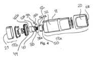
図4で分かるように、カプセル16は、複数の異なる部品から組み立てることができる。しかしながら、図示した実施形態は概略図であり、当業者には明らかとなる単一のユニットに、いくつかの部品を組み合わせることも可能である。複数の様々な部品の現在の構成は、カプセル16の効率的な組み立てを可能にする。As can be seen in FIG. 4, the
カプセルハウジング18は、上部ハウジング18aと、下部ハウジング18b又はベース18bとから形成されてもよい。部品は、上部ハウジング18aと下部ハウジング18bとの間の摩擦嵌めによって一緒に組み立てることができる。加えて又は代替として、上部ハウジング18a及び下部ハウジング18bを、超音波溶接によって一緒に結合させることができる。任意選択で、図示するように、上部ハウジング18aは、カプセルの上部ハウジング18aに組み立てられる別個の部品としてマウスピース部分20を備えてもよい。The
図3aを図4と併せると最もよく分かるように、気化チャンバ30は、カプセル16の、マウスピース部分20とは反対側の遠位端に配置され、気化ユニット34を収容する。気化チャンバ30からマウスピース部分20内の蒸気出口28まで主蒸気チャネルが画定され、これは管状の断面を有してもよい。主蒸気チャネル24は、マウスピースから遠位方向に離れるように延びるチューブ又はチムニー部24から形成されることができ、それが気化チャンバ30に密閉して接続されてもよい。好都合には、チューブ又はチムニー部24を、上部ハウジングと一体に形成することができる。この部品を、例えば、射出成形又は成形によって生産することができる。いったんチューブ又はチムニー部24が気化チャンバ30に接続されると、主蒸気蒸気チャネルが形成される。As best seen in FIG. 3a in conjunction with FIG. 4, the vaporization chamber 30 is located at the distal end of the
気化チャンバ30は、液体貯蔵部32に取り囲まれている。液体貯蔵部は、液体送達チャネル33を通してのみ液体を受け取り、空気入口35からのみ吸気を受け取り、(チューブ又はチムニー部24を介して)主蒸気チャネルを通してのみ蒸気を送達するように密閉されている。この趣旨で、気化ユニット34は、管状気化器ハウジング40の内部に収容されている。気化器ハウジングには、上部リム42a及び下部リム42bが設けられている。上部リム42aは第1のシール50と接触しており、下部リム42bは第2のシール44又は下部ガスケットと接触している。シール44及び50は、接続部を通る漏れを最小限に抑えるために、好ましくは弾性材料又は圧縮性材料でできている。材料は、例えばシリコーンであってもよい。下部ガスケット44は、管状気化器ハウジング40の外周の周囲を密閉するように構成されている。The vaporization chamber 30 is surrounded by a
気化ユニット34は、加熱要素36及び流体移送要素38を含む。流体移送要素38は、毛管作用によって液体Lを液体貯蔵部32から加熱要素36へと移動させるように構成されている。流体移送要素38は、対になった綿又はシリカから作製される芯などの繊維質の又は多孔質の要素とすることができる。代替として、流体移送要素38は任意の他の適切な多孔質要素であり得る。The
気化チャンバ30は、流体移送要素38によって液体貯蔵部32に流体的に接続されている。それゆえ、気化チャンバ30への液体入口は、流体移送要素38を介してのみ、及び流体移送要素38の多孔質構造から形成された液体送達チャネル33を介してのみ提供される。The vaporization chamber 30 is fluidly connected to the
流体移送要素38は、第1の端部38a及び第2の端部38bを有する。流体移送要素38は、細長く実質的に真っ直ぐな形状を備え、好ましくは、その長手方向延長部がカプセル16の長手方向に垂直に又は長手方向を横切るように置かれている。流体移送要素38は、液体貯蔵部32内に配置された液体取込み部分39a、及び気化チャンバ30内において加熱要素36と接触する液体送達部分39bを有する。The
液体取込み部分39aは、流体移送要素38の第1の端部38a及び第2の端部38bに対応する。加熱要素36は、流体移送要素38の液体送達部分39b上に置かれている。液体送達部分39bは、細長い流体移送要素38の中央部分に対応する。図に示す実施形態では、加熱要素36は、流体移送要素38の外周に設けられている。The liquid intake portion 39a corresponds to the
気化器ハウジング40には、一対の切り欠き48が更に設けられ、そこを通して流体移送要素38の第1の端部38a及び第2の端部38bが収容される。第1のシール50は、気化チャンバ30と流体移送要素38との間の接続部に配置されている。第1のシール50は、気化器ハウジング40の上部リム42aの形状に対応する接触面S1を有する。第1のシール50には開口部51が更に設けられ、そこを通して蒸気が気化チャンバ30から主蒸気流チャネルへと流れ得る。第1のシール50には、好ましくは、半径方向に延びるタブ52が設けられ、タブは切り欠き48内に収容され、カプセル16が組み立てられる時に流体移送要素38を押すように構成されている。第1のシール50は、流体移送要素38を流体移送要素38の半径方向に圧縮するように構成されている。流体移送要素38を圧縮することにより、液体貯蔵部32から気化チャンバ30への液体の流れは、流体移送要素38を通って導かれる。それゆえ、流体移送要素38の周囲の漏れが防止される。The
図5で最もよく分かるように、加熱要素36は、流体移送要素38の周囲に巻かれている。加熱ワイヤ36には、流体移送要素38の外径Dよりも小さい内部ボアBが設けられている。As best seen in FIG. 5, the
加熱ワイヤ36は、抵抗加熱によって流体移送要素38を加熱するように構成されている。有利な実施形態では、加熱ワイヤ36の材料はチタンであり得る。チタンは、例えば、ステンレス鋼又はニッケルと比較して、温度曲線に対して急な抵抗を有する。それゆえ、加熱ワイヤ36の抵抗は、コイル温度の上昇と共に比較的急速に増加する。しかしながら、ステンレス鋼、ニッケル、クロム、アルミニウム、又はそれらの合金などの他の材料も可能である。The
加熱コイル36はワイヤゲージ(すなわち、ワイヤ直径)dを備える。ワイヤ直径dは加熱コイル38の抵抗に影響を与える。ゲージdが大きくなると、電気抵抗は低くなる。加熱コイル36は、定められたピッチPで構成された巻数Nを備える。巻数N及び選択されたピッチPは、流体移送要素38に沿った加熱要素36からの温度及び熱分布に影響を与える。The
加熱ワイヤ36の全長Lは、ピッチP及び巻数Nと共に増加する。この結果、加熱要素36と流体移送要素38との間の接触表面積Cが増加する。しかしながら、流体移送要素38と加熱要素36との間の増加した接触面積Cはまた、加熱要素36を冷却する。その上、加熱ワイヤの抵抗は、ワイヤ長が増加するにつれて増加する。The overall length L of the
図5bで分かるように、加熱ワイヤ36の全円周Otの一部のみが流体移送要素38と接触している。この部分を、接触長さLcと称し得る。したがって、流体移送要素38と接触している加熱要素36の接触表面積Cは、接触長さLcに、流体移送要素38と接触している加熱ワイヤ36の全軸方向長さLaを乗じたものとして定義することができる。As can be seen in FIG. 5b, only a portion of the total circumference Ot of the
本体4は、カプセルの加熱要素36に電力を供給し、気化の動作全体を制御するように構成されている。本体4は、ほとんどの従来技術の電子タバコと比較して、コンパクトな装置として構成することができる。これは、電力ユニット6又は電池6のサイズが比較的小さいことを意味する。本発明の一実施形態では、電池は、約350mAhの出力を有するリチウム電池である。The
本体4の電気回路8は、電子タバコ2を動作させるように構成されており、流量センサ10又は手動作動スイッチ、メモリ11、及びコントローラ13を備えてもよい。電気回路8は、有利には、主回路基板上にグループ化されてもよい。The
コントローラ13は、電池出力のパルス幅変調を可能にするように構成されている。パルス幅変調は、加熱要素36の温度を制御し、電池電力の節約を可能にする。出力電力は、電池6が満充電されているか又は枯渇に近いかどうかに関係なく、出力電力が時間にわたって一定となるように変調される。現在の電池はサイズと出力電圧が比較的小さいので、これは有利である。The
吸入器本体は、好ましくは150mm未満の軸方向長さと20mm未満の厚さとを有するコンパクトな形状を備えていることが好ましい。好ましくは、装置は、手のひらに収まるであろう寸法を備えている。本電子タバコの特に好ましい寸法は、110mm未満であり、厚さは2cm未満である。電子タバコが小さくなるほど、電子タバコの中に収まるであろう電源又は電池は小さくなる。本発明者らは、効率的な電力供給及び効率的な気化を確実にすることによって、高いTPMが依然として実現可能であることを見出した。しかしながら、本発明の第1の実施形態のいくつかは十分な性能をもたらさなかった。図1a及び図1bに示すように、電子タバコのカプセル16及び吸入器本体は、軸方向に回転対称ではない形状を有する場合がある。したがって、カプセル16は平坦な長辺と短辺を有する矩形の基部を有する場合がある。The inhaler body preferably has a compact shape, preferably with an axial length of less than 150 mm and a thickness of less than 20 mm. Preferably, the device has dimensions that would fit in the palm of a hand. Particularly preferred dimensions of the present electronic cigarette are less than 110 mm and a thickness of less than 2 cm. The smaller the electronic cigarette, the smaller the power source or battery that would fit within it. The inventors have found that by ensuring efficient power delivery and efficient vaporization, a high TPM is still achievable. However, some of the first embodiments of the invention did not provide sufficient performance. As shown in Figures 1a and 1b, the
加熱要素の温度は効率的な気化が起こる温度であることを確実にすることが望ましい。これは、加熱コイルの温度が不十分な場合には、液体Lは、所望の気化状態ではなく、沸騰段階に入る傾向があるからである。液体が直接、気化状態に変化するように、加熱要素の温度を確実に充分に高くすることが望ましい。それにより、望ましくない液体吐出を軽減することができる。更に、望ましくない化学化合物の量を低レベルに保ちながら、高いTPM(総粒子状物質)を有する大量の蒸気を提供することが望ましいであろう。It is desirable to ensure that the temperature of the heating element is at a temperature where efficient vaporization occurs. This is because if the temperature of the heating coil is insufficient, the liquid L will tend to enter a boiling stage rather than the desired vaporized state. It is desirable to ensure that the temperature of the heating element is high enough so that the liquid changes directly to a vaporized state, thereby reducing undesirable liquid ejection. Furthermore, it would be desirable to provide a large volume of vapor with a high TPM (total particulate matter) while keeping the amount of undesirable chemical compounds at a low level.
本発明者らは、高い蒸気送達能力を備えるコンパクトな電子タバコの開発の任務が課せられている。この要件に基づいて、比較的高い電力密度が必要であると想定して、第1のプロトタイプを開発した。大部分が植物性グリセリン(VG)とプロピレングリコール(PG)の混合物であって、その比率がVG:PG=50:50であり、ニコチン1.59%、風味剤1%を含む試験液を使用した。The inventors were tasked with developing a compact e-cigarette with high vapor delivery capacity. Based on this requirement, and assuming a relatively high power density, a first prototype was developed. The test liquid used was a mixture of mostly vegetable glycerin (VG) and propylene glycol (PG) in a 50:50 ratio, containing 1.59% nicotine and 1% flavoring.
実施例1に従う第1のプロトタイプは、以下の通りに寸法設定されている:
実施例1
抵抗(Ω):1.96
幅(mm):4.40~4.80
ボア(mm):2.10~2.20
巻数:4.5
加熱ワイヤゲージ(mm):0.15
ピッチ(mm):1.0
TPM測定値(mg/パフ):3.3
電池出力、Vrms(V):3.55
電力密度1.3ワット/mm2
流体移送要素
流体移送要素の材料:綿
流体移送要素の密度(g/m):1.0
流体移送要素の長さ(mm):12.0
流体移送要素の直径(mm):3 A first prototype according to Example 1 is dimensioned as follows:
Example 1
Resistance (Ω): 1.96
Width (mm): 4.40-4.80
Bore (mm): 2.10-2.20
Number of volumes: 4.5
Heating wire gauge (mm): 0.15
Pitch (mm): 1.0
TPM reading (mg/puff): 3.3
Battery output, Vrms (V): 3.55
Power density 1.3 watts/mm2
Fluid Transport Element Fluid transport element material: cotton Fluid transport element density (g/m): 1.0
Fluid transport element length (mm): 12.0
Diameter of fluid transport element (mm): 3
この第1のプロトタイプの分析は、生成された蒸気量とTPMに関して完全に満足のいくものとは見なされなかった。加えて、望ましくない化学化合物のレベルを更に高めることを試みることが望まれた。したがって、本発明者らは、望ましくない化学化合物を低減させながら、蒸気量(TPM)を更に増加させることを試みるという課題に直面した。本発明者らは、望ましくない化合物が、加熱要素に沿った不規則な加熱温度によって形成される可能性があることを認識した。この不規則な温度は、流体移送要素内の液体の不均一な吸収、並びに加熱要素と流体移送要素との間の接触面の変動によって引き起こされる可能性がある。The analysis of this first prototype was not considered completely satisfactory in terms of the amount of vapor and the TPM generated. In addition, it was desired to try to further increase the level of undesirable chemical compounds. The inventors were therefore faced with the task of trying to further increase the amount of vapor (TPM) while reducing the undesirable chemical compounds. The inventors recognized that undesirable compounds may be formed due to an irregular heating temperature along the heating element. This irregular temperature may be caused by an uneven absorption of liquid in the fluid transport element as well as variations in the contact surface between the heating element and the fluid transport element.
これらの問題を克服するために、より均一な熱分布が必要であると、本発明者らは確信した。これは、加熱要素と流体移送要素との間の接触面の改善などの多くの手段によって実現することができる。この接触領域では、流体移送要素から加熱要素への流体分布の改善、並びに気化温度の最適化が必要であった。加えて、液体貯蔵部から加熱ワイヤの近傍への流体輸送は、有利な効果をもたらす可能性がある。同じ試験液を第2のプロトタイプに使用した。これらの認識に基づいて、実施例2の第2のプロトタイプは、以下の通りに寸法設定されている:
実施例2
抵抗(Ω):1.60
幅(mm):4.40
ボア(mm):2.0
巻数:7
加熱ワイヤゲージ(mm):0.2
ピッチ(mm):0.6
TPM測定値(mg/パフ):5.5
電池出力、Vrms(V):3.4
電力密度0.85ワット/mm2
流体移送要素
流体移送要素の材料:綿
流体移送要素の密度(g/m):1.0
流体移送要素の長さ(mm):12.0
流体移送要素の直径(mm):3 To overcome these problems, the inventors believed that a more uniform heat distribution was needed. This could be achieved by many means, such as improving the contact surface between the heating element and the fluid transport element. This contact area required improved fluid distribution from the fluid transport element to the heating element, as well as optimizing the vaporization temperature. In addition, fluid transport from the liquid reservoir to the vicinity of the heating wire could have beneficial effects. The same test liquid was used in the second prototype. Based on these realizations, the second prototype of Example 2 is dimensioned as follows:
Example 2
Resistance (Ω): 1.60
Width (mm): 4.40
Bore (mm): 2.0
Volumes: 7
Heating wire gauge (mm): 0.2
Pitch (mm): 0.6
TPM reading (mg/puff): 5.5
Battery output, Vrms (V): 3.4
Power density 0.85 watts/mm2
Fluid Transport Element Fluid transport element material: cotton Fluid transport element density (g/m): 1.0
Fluid transport element length (mm): 12.0
Diameter of fluid transport element (mm): 3
加熱要素コイルのボアサイズを低減させることにより、ワイヤはまた、流体移送要素のより深い位置に置かれた。これにより、加熱要素と流体移送要素との間の接触面積は更に増加した。これは、加熱ワイヤの一部のみが、実際に流体移送要素と直接接触しているからである。加熱要素と流体移送要素との間の実効的接触面積は、流体移送要素と接触している加熱コイルの全表面積の30%であると決定された。By reducing the bore size of the heating element coil, the wire was also placed deeper into the fluid transfer element. This further increased the contact area between the heating element and the fluid transfer element, as only a portion of the heating wire was actually in direct contact with the fluid transfer element. The effective contact area between the heating element and the fluid transfer element was determined to be 30% of the total surface area of the heating coil in contact with the fluid transfer element.
好ましい実施形態では、加熱要素の内部ボアは、流体移送要素の外径の50~70%に対応する。より好ましくは、加熱要素の内部ボアは、流体移送要素の外径の66%に対応する。これにより、加熱要素と流体移送要素との間の接触面が増加することにより、加熱要素と流体移送要素との間の効率的な熱伝達が確実になる。その上、ヒーター付近で流体移送要素を局所的に圧縮することにより、毛細管現象が局所的に増加する。これはまた、加熱要素への液体輸送が強化されるという効果を有する。In a preferred embodiment, the internal bore of the heating element corresponds to 50-70% of the outer diameter of the fluid transport element. More preferably, the internal bore of the heating element corresponds to 66% of the outer diameter of the fluid transport element. This ensures efficient heat transfer between the heating element and the fluid transport element by increasing the contact surface between them. Moreover, the local compression of the fluid transport element near the heater locally increases the capillary action. This also has the effect of enhancing the liquid transport to the heating element.
それゆえ、加熱要素の特性が変更された一方で、流体移送要素の特性は同じままであった。第2のプロトタイプの結果は満足であった。TPMは67%増加したが、一方でカルボニルの測定値は大幅に低減した。例えば、ホルムアルデヒドは30パフ当たり99μgから30パフ当たり1.5μgに減少した。Thus, the characteristics of the heating element were changed, while the characteristics of the fluid transfer element remained the same. The results of the second prototype were satisfactory: TPM increased by 67%, while the carbonyl measurements were significantly reduced. For example, formaldehyde decreased from 99 μg per 30 puffs to 1.5 μg per 30 puffs.
更なる分析により、気化ユニットの有利な寸法は、次のようであり得ることが確認された:
電力密度は、0.7~1.0ワット/mm2、好ましくは0.80~0.85ワット/mm2、より好ましくは約0.847ワット/mm2である。
加熱ワイヤゲージは、0.18mmより大きい、好ましくは0.18~0.22mmである、最も好ましくは約0.2mmである。 Further analysis has determined that advantageous dimensions for the vaporization unit may be as follows:
The power density is between 0.7 and 1.0 Watts/mm2, preferably between 0.80 and 0.85 Watts/mm2, and more preferably about 0.847 Watts/mm2.
The heating wire gauge is greater than 0.18 mm, preferably between 0.18 and 0.22 mm, and most preferably about 0.2 mm.
加熱ワイヤの表面積の20~40%、好ましくは30~35%、最も好ましくは約30%である、流体移送要素と接触している加熱要素の表面積の実効的パーセンテージ。The effective percentage of the heating element's surface area in contact with the fluid transport element is 20-40%, preferably 30-35%, and most preferably about 30% of the heating wire's surface area.
当業者であれば、本発明は説明された例示的実施形態に決して限定されないことを理解するであろう。特定の対応策が互いに異なる従属請求項において挙げられているという単なる事実は、これらの対応策の組合せが有利に使用され得ないということを示すものではない。更に、「含む」という表現は他の要素又はステップを排除しない。他の非限定的な表現は、「1つの(a)」又は「1つの(an)」が複数を排除しないこと、及び単一のユニットがいくつかの手段の機能を満たし得ることを含む。特許請求の範囲におけるいずれの参照符号も範囲を限定すると解釈されるべきではない。最後に、本発明は図面及び前述の説明において詳細に例証されてきたが、そのような例証及び説明は、限定的ではなく例証的又は例示的なものと見なされ、本発明は開示された実施形態に限定されない。Those skilled in the art will understand that the present invention is in no way limited to the exemplary embodiments described. The mere fact that certain measures are recited in mutually different dependent claims does not indicate that a combination of these measures cannot be advantageously used. Moreover, the term "comprises" does not exclude other elements or steps. Other non-limiting expressions include that "a" or "an" does not exclude a plurality, and that a single unit may fulfill the functions of several means. Any reference signs in the claims should not be construed as limiting the scope. Finally, although the present invention has been illustrated in detail in the drawings and the foregoing description, such illustration and description are to be regarded as illustrative or exemplary rather than restrictive, and the present invention is not limited to the disclosed embodiments.
Claims (15)
Translated fromJapanese前記カプセルは、
気化される液体を収容するように構成されている液体貯蔵部と、
気化チャンバと、
蒸気出口と、
加熱要素及び流体移送要素を備える気化ユニットであって、前記流体移送要素が、前記液体貯蔵部内に配置された液体取込み部分及び前記気化チャンバ内において前記加熱要素と接触する液体送達部分を有する、気化ユニットと、
前記気化チャンバから前記蒸気出口まで延びる主蒸気流チャネルと、
前記気化チャンバと前記主蒸気流チャネルとを密閉接続するように構成された第1のシールであって、前記第1のシールは、前記気化チャンバの中への液体の流れを制御するために、前記流体移送要素を前記流体移送要素の半径方向に圧縮するように更に構成されている、第1のシールと、
を備え、
前記第1のシールは、前記第1のシールの半径方向に延び、前記カプセルが組み立てられた状態で、前記流体移送要素を押すように構成されたタブを有する、
電子タバコ。 An electronic cigarette comprising an inhaler body and a removable capsule, the inhaler body including a power unit, a control circuit, and a capsule seat configured to interface with the capsule;
The capsule comprises:
a liquid reservoir configured to contain a liquid to be vaporized;
A vaporization chamber;
A steam outlet;
a vaporization unit comprisinga heating element and a fluid transport element, the fluid transport element having a liquid intake portion disposed within the liquid reservoir and a liquid delivery portion in contact withthe heating element within the vaporization chamber;
a main vapor flow channel extending from the vaporization chamber to the vapor outlet;
a first seal configured to sealingly connect the vaporization chamber and the main vapor flow channel, the first seal further configured to compress the fluid transport element in a radial direction of the fluid transport element to control a flow of liquid into the vaporization chamber;
Equipped with
the first seal having a tab extending radially therefrom and configured to press against the fluid transfer element when the capsule is assembled;
Electronic Cigarette.
請求項1に記載の電子タバコ。 The electronic cigarette is configured to power theheating element to provide an effective power density of 0.7 to 1.0 Watts/mm2.
The electronic cigarette of claim 1.
請求項1又は2に記載の電子タバコ。The heating element is a heating wire, and the gauge of the heating wire is greater than 0.18 mm;
3. The electronic cigarette according to claim 1 or 2.
請求項2を引用する請求項3に記載の電子タバコ。 the effective percentage of the surface area of the heating element in contact with the fluid transport element is between 20 and 40% of the surface area of the heating wire;
The electronic cigarette according to claim 3 which recites claim 2.
前記吸入は55mlの体積に対応する、
請求項1~4のいずれか一項に記載の電子タバコ。 the vaporization unit is configured to generate an aerosol having a vapor density of at least 3.5 mg per inhalation;
The inhalation corresponds to a volume of 55 ml.
The electronic cigarette according to any one of claims 1 to 4.
請求項1~4のいずれか一項に記載の電子タバコ。 The vaporization unit is configured to generate an aerosol having a vapor density of at least 5.5 mg per 55 ml inhalation.
The electronic cigarette according to any one of claims 1 to 4.
請求項1~6のいずれか一項に記載の電子タバコ。 the control circuitry is configured to provide pulse width modulation control such that constant power is produced from the power unit over a predetermined range of power unit voltage levels.
The electronic cigarette according to any one of claims 1 to 6.
請求項1~7のいずれか一項に記載の電子タバコ。 The inhaler body has an axial length of less than 120 mm.
The electronic cigarette according to any one of claims 1 to 7.
請求項1~8のいずれか一項に記載の電子タバコ。 the fluid transport element has a longitudinal extension perpendicular to the longitudinal direction of the capsule;
The electronic cigarette according to any one of claims 1 to 8.
請求項9に記載の電子タバコ。 The heating element is disposed on the outer periphery of the fluid transport element.
10. The electronic cigarette of claim 9.
請求項10に記載の電子タバコ。 The heating element is wrapped around the fluid transport element.
The electronic cigarette of claim 10.
請求項11に記載の電子タバコ。 liquid inlet to the vaporization chamber is provided only through the fluid transport element and only through liquid delivery channels formed from a porous structure of the fluid transport element;
The electronic cigarette of claim 11.
前記カプセルは、電子タバコ装置と係合するための第1の端部と、蒸気出口を有するマウスピース部分として構成される第2の端部とを有し、
気化される液体を収容するように構成されている液体貯蔵部と、
気化チャンバと、
蒸気出口と、
加熱要素及び流体移送要素を備える気化ユニットであって、前記流体移送要素が、前記液体貯蔵部内に配置された液体取込み部分及び前記気化チャンバ内において前記加熱要素と接触する液体送達部分を有する、気化ユニットと、
前記気化チャンバから前記蒸気出口まで延びる主蒸気流チャネルと、
前記気化チャンバと前記主蒸気流チャネルとを密閉して接続するように構成された第1のシールであって、前記第1のシールは、前記気化チャンバの中への液体の流れを制御するために、前記流体移送要素を前記流体移送要素の半径方向に圧縮するように構成されている、第1のシールと、
を更に備え、
前記第1のシールは、前記第1のシールの半径方向に延び、前記カプセルが組み立てられた状態で、前記流体移送要素を押すように構成されたタブを有する、
カプセル。 A capsule for an electronic cigarette, comprising:
the capsule has a first end for engaging an electronic cigarette device and a second end configured as a mouthpiece portion having a vapor outlet;
a liquid reservoir configured to contain a liquid to be vaporized;
A vaporization chamber;
A steam outlet;
a vaporization unit comprisinga heating element and a fluid transport element, the fluid transport element having a liquid intake portion disposed within the liquid reservoir and a liquid delivery portion in contact withthe heating element within the vaporization chamber;
a main vapor flow channel extending from the vaporization chamber to the vapor outlet;
a first seal configured to sealingly connect the vaporization chamber and the main vapor flow channel, the first seal configured to compress the fluid transport element in a radial direction of the fluid transport element to control a flow of liquid into the vaporization chamber;
Further comprising:
the first seal having a tab extending radially therefrom and configured to press against the fluid transfer element when the capsule is assembled;
capsule.
請求項13に記載のカプセル。the heating element is a heating wire, and the effective circumferenceof the heating element in contact withthe fluid transport element is between 20% and 40% of the circumference of the heating wire;
The capsule of claim 13.
請求項13又は14に記載のカプセル。 The vapour outlet is provided as a mouthpiece portion of the capsule.
15. A capsule according to claim 13 or 14.
Applications Claiming Priority (3)
| Application Number | Priority Date | Filing Date | Title |
|---|---|---|---|
| EP18188590 | 2018-08-10 | ||
| EP18188590.6 | 2018-08-10 | ||
| PCT/EP2019/071456WO2020030792A1 (en) | 2018-08-10 | 2019-08-09 | Electronic cigarette and capsule for an electronic cigarette |
Publications (2)
| Publication Number | Publication Date |
|---|---|
| JP2021532767A JP2021532767A (en) | 2021-12-02 |
| JP7519988B2true JP7519988B2 (en) | 2024-07-22 |
Family
ID=63209333
Family Applications (1)
| Application Number | Title | Priority Date | Filing Date |
|---|---|---|---|
| JP2021504816AActiveJP7519988B2 (en) | 2018-08-10 | 2019-08-09 | Electronic cigarettes and capsules for electronic cigarettes |
Country Status (8)
| Country | Link |
|---|---|
| US (1) | US12075828B2 (en) |
| EP (1) | EP3833202A1 (en) |
| JP (1) | JP7519988B2 (en) |
| KR (1) | KR20210038889A (en) |
| CN (1) | CN112512353A (en) |
| CA (1) | CA3107669A1 (en) |
| EA (1) | EA202190198A1 (en) |
| WO (1) | WO2020030792A1 (en) |
Families Citing this family (10)
| Publication number | Priority date | Publication date | Assignee | Title |
|---|---|---|---|---|
| US11405987B2 (en)* | 2018-12-10 | 2022-08-02 | Tuanfang Liu | Electronic cigarette with an e-liquid inlet that is reliably sealed |
| CN115190769A (en)* | 2020-02-28 | 2022-10-14 | 日本烟草国际股份有限公司 | Capsule and seal for an electronic cigarette |
| EP4110107A1 (en)* | 2020-02-28 | 2023-01-04 | JT International SA | Capsule seals |
| WO2021170767A1 (en)* | 2020-02-28 | 2021-09-02 | Jt International Sa | Embedded electrodes |
| CN115243572A (en)* | 2020-02-28 | 2022-10-25 | 日本烟草国际股份有限公司 | Airflow chimney |
| WO2022034053A1 (en)* | 2020-08-14 | 2022-02-17 | Jt International Sa | Capsule with an airflow path for an electronic cigarette |
| EP4297598A1 (en) | 2021-02-25 | 2024-01-03 | JT International SA | Electronic cigarette and method for controlling an electronic cigarette |
| US20230284693A1 (en)* | 2022-03-10 | 2023-09-14 | Nicoventures Trading Limited | Aerosol provision system |
| CN117617562A (en)* | 2022-08-24 | 2024-03-01 | 上海琨纬科技有限公司 | Electronic atomizer and manufacturing method thereof |
| USD1079112S1 (en)* | 2023-02-27 | 2025-06-10 | Aspire North America Llc | Electronic cigarette |
Citations (7)
| Publication number | Priority date | Publication date | Assignee | Title |
|---|---|---|---|---|
| WO2011122474A1 (en) | 2010-03-29 | 2011-10-06 | 日本たばこ産業株式会社 | Liquid tank for aerosol aspirator |
| JP2014525237A (en) | 2011-08-09 | 2014-09-29 | アール・ジエイ・レイノルズ・タバコ・カンパニー | Smoking article and using the smoking article to provide suction material |
| US20160073692A1 (en) | 2014-09-17 | 2016-03-17 | Fontem Holdings 2 B.V. | Device for storing and vaporizing liquid media |
| US20160213065A1 (en) | 2015-01-22 | 2016-07-28 | Fontem Holdings 1 B.V. | Electronic vaporization devices |
| JP2017513465A (en) | 2014-03-12 | 2017-06-01 | アール・エイ・アイ・ストラテジック・ホールディングス・インコーポレイテッド | Aerosol delivery system and related methods, apparatus, and computer program products for providing control information to an aerosol delivery device by a cartridge |
| US20170251725A1 (en) | 2014-08-26 | 2017-09-07 | Nicoventures Holdings Limited | Electronic aerosol provision system |
| US20170258132A1 (en) | 2016-03-08 | 2017-09-14 | Altria Client Services Llc | Combined cartridge for electronic vaping device |
Family Cites Families (6)
| Publication number | Priority date | Publication date | Assignee | Title |
|---|---|---|---|---|
| GB2504074A (en)* | 2012-07-16 | 2014-01-22 | Nicoventures Holdings Ltd | Electronic cigarette |
| WO2014190079A2 (en)* | 2013-05-22 | 2014-11-27 | Njoy, Inc. | Compositions, devices, and methods for nicotine aerosol delivery |
| CN103584286A (en) | 2013-11-12 | 2014-02-19 | 深圳市合元科技有限公司 | Atomizer, electronic cigarette and atomization head for electronic cigarette |
| WO2015077645A1 (en) | 2013-11-21 | 2015-05-28 | Corr-Tech Associates, Inc. | Improved vaporization and dosage control for electronic vaporizing inhaler |
| CN204444245U (en) | 2015-01-05 | 2015-07-08 | 深圳市合元科技有限公司 | Removable atomization unit and the atomizer and the electronic cigarette that comprise this atomization unit |
| CN108366621B (en) | 2015-10-08 | 2020-10-27 | 富特姆控股第一有限公司 | Liquid supply device of electronic smoking device |
- 2019
- 2019-08-09CACA3107669Apatent/CA3107669A1/ennot_activeAbandoned
- 2019-08-09WOPCT/EP2019/071456patent/WO2020030792A1/ennot_activeCeased
- 2019-08-09USUS17/266,266patent/US12075828B2/enactiveActive
- 2019-08-09EAEA202190198Apatent/EA202190198A1/enunknown
- 2019-08-09CNCN201980050482.2Apatent/CN112512353A/enactivePending
- 2019-08-09EPEP19752502.5Apatent/EP3833202A1/enactivePending
- 2019-08-09KRKR1020217002931Apatent/KR20210038889A/ennot_activeWithdrawn
- 2019-08-09JPJP2021504816Apatent/JP7519988B2/enactiveActive
Patent Citations (9)
| Publication number | Priority date | Publication date | Assignee | Title |
|---|---|---|---|---|
| WO2011122474A1 (en) | 2010-03-29 | 2011-10-06 | 日本たばこ産業株式会社 | Liquid tank for aerosol aspirator |
| JP2014525237A (en) | 2011-08-09 | 2014-09-29 | アール・ジエイ・レイノルズ・タバコ・カンパニー | Smoking article and using the smoking article to provide suction material |
| JP2017513465A (en) | 2014-03-12 | 2017-06-01 | アール・エイ・アイ・ストラテジック・ホールディングス・インコーポレイテッド | Aerosol delivery system and related methods, apparatus, and computer program products for providing control information to an aerosol delivery device by a cartridge |
| US20170251725A1 (en) | 2014-08-26 | 2017-09-07 | Nicoventures Holdings Limited | Electronic aerosol provision system |
| JP2017532011A (en) | 2014-08-26 | 2017-11-02 | ニコベンチャーズ ホールディングス リミテッド | Electronic aerosol supply device |
| US20160073692A1 (en) | 2014-09-17 | 2016-03-17 | Fontem Holdings 2 B.V. | Device for storing and vaporizing liquid media |
| US20160213065A1 (en) | 2015-01-22 | 2016-07-28 | Fontem Holdings 1 B.V. | Electronic vaporization devices |
| JP2018504926A (en) | 2015-01-22 | 2018-02-22 | フォンテム ホールディングス 1 ベー.ハー.Fontem Holdings 1 B.V. | Electronic vaporizer |
| US20170258132A1 (en) | 2016-03-08 | 2017-09-14 | Altria Client Services Llc | Combined cartridge for electronic vaping device |
Also Published As
| Publication number | Publication date |
|---|---|
| WO2020030792A1 (en) | 2020-02-13 |
| CN112512353A (en) | 2021-03-16 |
| EA202190198A1 (en) | 2021-06-30 |
| US20210298357A1 (en) | 2021-09-30 |
| EP3833202A1 (en) | 2021-06-16 |
| JP2021532767A (en) | 2021-12-02 |
| CA3107669A1 (en) | 2020-02-13 |
| KR20210038889A (en) | 2021-04-08 |
| US12075828B2 (en) | 2024-09-03 |
Similar Documents
| Publication | Publication Date | Title |
|---|---|---|
| JP7519988B2 (en) | Electronic cigarettes and capsules for electronic cigarettes | |
| US12403273B2 (en) | Aerosol delivery device with a reservoir housing and a vaporizer assembly | |
| US20240324678A1 (en) | Aerosol delivery device, and associated apparatus and method of formation thereof | |
| KR102203852B1 (en) | Apparatus and system for generating aerosols | |
| CN111479477B (en) | Aerosol delivery device including a control body, a nebulizer body, and a cartridge, and related methods | |
| JP7568622B2 (en) | Atomizer and aerosol generating system including the atomizer | |
| KR102707899B1 (en) | Differential pressure sensor for aerosol delivery device | |
| CN113226079B (en) | Heaters and liquid transport components for aerosol delivery systems | |
| KR102471453B1 (en) | Electrically-powered aerosol delivery system | |
| US20150351456A1 (en) | Electronic cigarette | |
| EP0358114A2 (en) | Aerosol delivery articles utilizing electrical energy | |
| CA3087287A1 (en) | Aerosol delivery device providing flavor control | |
| CN111031817A (en) | Aerosol Delivery Devices and Related Methods | |
| CN108024567A (en) | Liquid formulation for electrical steam cigarette device | |
| KR102503276B1 (en) | Cartridge and Aerosol generating device comprising thereof | |
| KR102840862B1 (en) | Leak-protected aerosol generating system and cartridge | |
| US20230112161A1 (en) | Capsule and Seals for an Electronic Cigarette | |
| EP4110107A1 (en) | Capsule seals | |
| CN113811209A (en) | Insert for use with evaporator device | |
| RU2805451C2 (en) | Nebulizer for electrically heated aerosol generating system, electrically heated aerosol generating system (embodiments) and cartridge for aerosol generating system | |
| RU2846974C2 (en) | Heater assembly for aerosol-generating system | |
| JP2025148585A (en) | Flavor inhaler and smoking system | |
| RU2835129C1 (en) | Aerosol delivery device with reservoir housing and evaporator unit | |
| JP2025504119A (en) | CARTRIDGE FOR AEROSOL GENERATION SYSTEM AND AEROSOL GENERATION SYSTEM WITH IMPROVED LIQUID DELIVERY - Patent application | |
| KR20230112363A (en) | Aerosol generating device |
Legal Events
| Date | Code | Title | Description |
|---|---|---|---|
| A621 | Written request for application examination | Free format text:JAPANESE INTERMEDIATE CODE: A621 Effective date:20220707 | |
| A977 | Report on retrieval | Free format text:JAPANESE INTERMEDIATE CODE: A971007 Effective date:20230614 | |
| A131 | Notification of reasons for refusal | Free format text:JAPANESE INTERMEDIATE CODE: A131 Effective date:20230619 | |
| A601 | Written request for extension of time | Free format text:JAPANESE INTERMEDIATE CODE: A601 Effective date:20230906 | |
| A521 | Request for written amendment filed | Free format text:JAPANESE INTERMEDIATE CODE: A523 Effective date:20231219 | |
| A131 | Notification of reasons for refusal | Free format text:JAPANESE INTERMEDIATE CODE: A131 Effective date:20240313 | |
| A521 | Request for written amendment filed | Free format text:JAPANESE INTERMEDIATE CODE: A523 Effective date:20240613 | |
| TRDD | Decision of grant or rejection written | ||
| A01 | Written decision to grant a patent or to grant a registration (utility model) | Free format text:JAPANESE INTERMEDIATE CODE: A01 Effective date:20240702 | |
| A61 | First payment of annual fees (during grant procedure) | Free format text:JAPANESE INTERMEDIATE CODE: A61 Effective date:20240709 | |
| R150 | Certificate of patent or registration of utility model | Ref document number:7519988 Country of ref document:JP Free format text:JAPANESE INTERMEDIATE CODE: R150 |