JP7519393B2 - Seat-mounted airbag device - Google Patents
Seat-mounted airbag deviceDownload PDFInfo
- Publication number
- JP7519393B2 JP7519393B2JP2022021698AJP2022021698AJP7519393B2JP 7519393 B2JP7519393 B2JP 7519393B2JP 2022021698 AJP2022021698 AJP 2022021698AJP 2022021698 AJP2022021698 AJP 2022021698AJP 7519393 B2JP7519393 B2JP 7519393B2
- Authority
- JP
- Japan
- Prior art keywords
- airbag
- airbag device
- chamber
- seat
- occupant
- Prior art date
- Legal status (The legal status is an assumption and is not a legal conclusion. Google has not performed a legal analysis and makes no representation as to the accuracy of the status listed.)
- Active
Links
- 210000000689upper legAnatomy0.000claimsdescription14
- 239000004744fabricSubstances0.000claimsdescription12
- 238000009958sewingMethods0.000claimsdescription12
- 210000004197pelvisAnatomy0.000claimsdescription2
- 230000000452restraining effectEffects0.000claims1
- 238000005192partitionMethods0.000description9
- 238000010586diagramMethods0.000description8
- 238000000034methodMethods0.000description5
- 240000004050Pentaglottis sempervirensSpecies0.000description4
- 235000004522Pentaglottis sempervirensNutrition0.000description4
- 230000006835compressionEffects0.000description4
- 238000007906compressionMethods0.000description4
- 230000003213activating effectEffects0.000description3
- 210000001624hipAnatomy0.000description3
- JOYRKODLDBILNP-UHFFFAOYSA-NEthyl urethaneChemical compoundCCOC(N)=OJOYRKODLDBILNP-UHFFFAOYSA-N0.000description2
- 239000006260foamSubstances0.000description2
- 210000003127kneeAnatomy0.000description2
- 239000010985leatherSubstances0.000description2
- 239000000203mixtureSubstances0.000description2
- 210000001015abdomenAnatomy0.000description1
- 230000004913activationEffects0.000description1
- 230000006978adaptationEffects0.000description1
- 230000000694effectsEffects0.000description1
- 238000005096rolling processMethods0.000description1
Images


Landscapes
- Seats For Vehicles (AREA)
- Air Bags (AREA)
Description
Translated fromJapanese本発明は、車両用シートに内蔵されるエアバッグ装置に関する。The present invention relates to an airbag device that is built into a vehicle seat.
車両の事故発生時に乗員を保護するために、1つまたは複数のエアバッグを車両に設けることは周知である。エアバッグとしては、例えば、自動車のステアリングホイールの中心付近から膨張して運転者を保護する、いわゆる運転者用エアバッグ、自動車の窓の内側で下方向に展開して車両横方向の衝撃や横転、転覆事故時に乗員を保護するカーテンエアバッグ、車両横方向の衝撃時に乗員を保護すべく乗員とサイドパネルとの間で展開するサイドエアバッグなどの様々な形態がある。It is well known that vehicles are provided with one or more airbags to protect occupants in the event of a vehicle accident. Airbags come in a variety of forms, including driver airbags that inflate from near the center of the steering wheel to protect the driver, curtain airbags that deploy downward inside the vehicle window to protect occupants in the event of a lateral impact or rollover, and side airbags that deploy between the occupant and the side panel to protect the occupant in the event of a lateral impact.
車両が前方衝突した場合、慣性によって乗員は前方へ移動しようとするため、乗客がシートベルトから抜けて座席から滑り落ち、足元の空間にもぐり込んでしまう、所謂「サブマリン現象」が発生する場合がある。特に、座席のリクライニングを倒した体勢だと、サブマリン現象が起こりやすくなる。サブマリン現象が発生すると、シートベルトが乗員の腹部や胸部、最悪の場合には頚部に引っ掛かり当該部位を圧迫する恐れがある。When a vehicle collides head-on, inertia causes occupants to move forward, which can cause passengers to slip out of their seat belts and slide off their seats into the space at their feet, a phenomenon known as "submarining." Submarining is particularly likely to occur when the seat is reclined. When the submarining occurs, the seat belt can get caught on the occupant's abdomen or chest, or in the worst case scenario, around the neck, putting pressure on those areas.
このため、特許文献1に示すように、シート内のエアバッグを膨張させることでシートクッションの前端部分を上昇させ、乗員の腰部の前方移動を拘束する発明が提案されている。For this reason, an invention has been proposed in which an airbag inside the seat is inflated to raise the front end of the seat cushion and restrain the forward movement of the occupant's hips, as shown in
しかしながら、特許文献1に記載された発明等の既存の方法では、正面衝突が発生した時にサブマリン現象を抑制できるものの、側面衝突が発生したときには、効果的に乗員を拘束することが困難であった。すなわち、側面衝突によって乗員の横方向へのスライドを拘束することはできず、サイドエアバッグ等の他のエアバッグに依存する必要があった。However, while existing methods such as the invention described in
本発明は上記のような状況に鑑みてなされたものであり、側面衝突の際に乗員の横方向への移動を効果的に拘束可能なエアバッグ装置を提供することを目的とする。The present invention was made in consideration of the above-mentioned circumstances, and aims to provide an airbag device that can effectively restrain the lateral movement of an occupant during a side collision.
上記のような目的を達成するために、本発明は、車両用シートの座面下部に収容されるエアバッグ装置であって、当該エアバッグ装置は、シートの座面の左右に配置され、各々独立して動作可能な左側エアバッグモジュールと、右側エアバッグモジュールとを含む。 前記左側エアバッグモジュールと前記右側エアバッグモジュールの各々は、膨張展開することで乗員を拘束するエアバッグと、前記エアバッグに対して膨張ガスを供給するガス発生器とを含む。そして、前記エアバッグは、乗員の大腿部の下で膨張展開する下部チャンバと、乗員の大腿部の外側部で膨張展開する側部チャンバとを含む。In order to achieve the above object, the present invention provides an airbag device housed under the seat cushion of a vehicle seat, the airbag device including a left airbag module and a right airbag module that are disposed on the left and right sides of the seat cushion and can each operate independently. Each of the left airbag module and the right airbag module includes an airbag that inflates and deploys to restrain an occupant, and a gas generator that supplies inflation gas to the airbag. The airbag includes a lower chamber that inflates and deploys under the thighs of the occupant, and a side chamber that inflates and deploys on the outer sides of the thighs of the occupant.
ここで、「シートの座面下部」とは、乗員が着座するシートクッション部分の内部を意味するものである。Here, "the lower part of the seat" refers to the inside of the seat cushion where the occupant sits.
上記のような本発明においては、各々独立して動作可能な左側エアバッグモジュールと、右側エアバッグモジュールとを備えているため、これらのエアバッグモジュールを衝突の形態に応じて選択的に起動することができ、効果的に乗員を拘束することが可能となる。The present invention as described above has a left airbag module and a right airbag module that can each operate independently, so these airbag modules can be selectively activated depending on the type of collision, making it possible to effectively restrain the occupant.
また、エアバッグが大腿部の下で膨張展開する下部チャンバと、大腿部の祖側部で膨張展開する側部チャンバとを備えているため、下部チャンバによって乗員の前方への移動が拘束され、所謂サブマリン現象を回避することが可能となる。更に、側部チャンバによって乗員の横方向の移動を拘束することができ、側面衝突の際の乗員保護性能が向上することになる。In addition, because the airbag has a lower chamber that inflates and deploys under the thighs, and a side chamber that inflates and deploys on the side of the thighs, the lower chamber restrains the occupant from moving forward, making it possible to avoid the so-called submarine phenomenon. Furthermore, the side chambers can restrain the occupant from moving sideways, improving occupant protection performance in the event of a side collision.
車両の正面衝突が発生したときは、前記左側エアバッグモジュールと前記右側エアバッグモジュールの両方を起動することができる。When a frontal vehicle collision occurs, both the left and right airbag modules can be activated.
左右両方のエアバッグモジュールを起動することによって、乗員の左右両方の大腿部の前方部分が持ち上がり、乗員の腰部が前方にスライドするのを効果的に抑制することができる。By activating both the left and right airbag modules, the front portions of both the left and right thighs of the occupant are raised, effectively preventing the occupant's hips from sliding forward.
車両の左側からの側面衝突が発生したときは、前記左側エアバッグモジュールを起動し、 車両の右側からの側面衝突が発生したときは、前記右側エアバッグモジュールを起動することができる。When a side impact occurs on the left side of the vehicle, the left airbag module can be activated, and when a side impact occurs on the right side of the vehicle, the right airbag module can be activated.
車両の左側からの側面衝突が発生したときは、乗員は慣性によってシートに対して左方向に移動しようとするが、その左方向への移動を左側エアバッグモジュールの側部チャンバによって規制することができる。また、下部チャンバによって座面の左側のみが持ち上がるため、座面の左側が右側よりも高くなり、乗員が左側に移動する際の抵抗となり、左方向への移動を効果的に抑制することができる。なお、右側からの側面衝突の場合も同様である。When a side collision occurs from the left side of the vehicle, the occupant will tend to move leftward relative to the seat due to inertia, but this movement to the left can be restricted by the side chamber of the left airbag module. Also, because only the left side of the seat surface is raised by the lower chamber, the left side of the seat surface becomes higher than the right side, providing resistance to the occupant's movement to the left and effectively restricting movement to the left. The same applies in the case of a side collision from the right side.
車両の側面衝突が発生したときは、当該衝突の側(ニアサイド)のエアバッグモジュールを起動する一次展開を行い、続いて、当該衝突と反対側(ファーサイド)のエアバッグモジュールを起動する二次展開を行うことができる。When a side collision occurs, a primary deployment can be performed to activate the airbag module on the side of the collision (near side), followed by a secondary deployment to activate the airbag module on the opposite side of the collision (far side).
上記のように一次展開と二次展開に時間差を設けるという動作は、一次展開と二次展開との起動時間にタイムラグがあり、ニアサイド側からファーサイド側に乗員が動くタイミングに合わせて左右各々のエアバッグをフル展開させるタイミング(時間)を制御する意味を含むものである。The operation of setting a time difference between the primary and secondary deployment as described above means that there is a time lag between the activation time of the primary and secondary deployment, and the timing (time) of the full deployment of each of the left and right airbags is controlled to match the movement of the occupant from the near side to the far side.
車両の左側から側面衝突が発生した直後は、上述したように、乗員は左側に移動するが、その後は、反動で右側に振り戻される(リバウンドする)ことになる。左側エアバッグモジュールの起動から若干遅れて右側エアバッグモジュールを起動すると、右側に振り戻された乗員の右方向への移動を拘束することができ、右隣席の他の乗員との接触を回避することが可能となる。なお、右側からの側面衝突の場合も同様である。Immediately after a side collision occurs from the left side of the vehicle, as mentioned above, the occupant will move to the left, but then will be swung back to the right (rebound) due to the reaction force. If the right airbag module is activated with a slight delay after the left airbag module is activated, the occupant who has been swung back to the right can be restrained from moving to the right, making it possible to avoid contact with the other occupant in the seat adjacent to the right. The same applies in the case of a side collision from the right side.
前記二次展開の際に、前記一次展開で起動したエアバッグモジュールのエアバッグのガスを外部に放出することができる。ガスの排気は、アクティブベントを使用して行うことができる。During the secondary deployment, the gas in the airbag of the airbag module activated during the primary deployment can be released to the outside. The gas can be exhausted using an active vent.
例えば、車両の左側から側面衝突が発生し、二次展開で右側エアバッグモジュールを起動するタイミングで、一次展開によって膨張展開した左側エアバッグモジュールのガスを排気することにより、左側エアバッグモジュールが萎むことになる。そのため、座面の左側に比べて右側が高くなり、乗員が右側にスライドし難くなる。その結果、右側エアバッグモジュールの展開によって乗員が振り戻されて右方向に移動するの規制する機能を、更に効果的に発揮することが可能となる。なお、右側からの側面衝突の場合も同様である。For example, if a side collision occurs from the left side of the vehicle, and the right airbag module is activated by secondary deployment, the gas in the left airbag module that was inflated and deployed by primary deployment is exhausted, causing the left airbag module to deflate. This makes the right side of the seat higher than the left side, making it difficult for the occupant to slide to the right. As a result, the right airbag module can be deployed to more effectively restrict the occupant from being swung back and moving to the right. The same applies to a side collision from the right side.
前記衝突と反対側のファーサイドのシートでは、前記二次展開を行わない構成とすることができる。The seats on the far side opposite the collision site can be configured not to undergo secondary deployment.
前記下部チャンバは、座面の前後方向の中心よりも前方に偏って膨張展開することができる。The lower chamber can be inflated and deployed in a position biased forward from the center of the seat in the fore-and-aft direction.
ここで、「前方に偏って」とは、下部チャンバの前後方向の中心が座面の中心よりも前方に位置する状態を意味し、必ずしも下部チャンバの全体が座面中心よりも前方に位置する必要はない。また、下部チャンバ自体が座面の前方に偏って配置される場合と、下部チャンバが座面の中心付近もしくは中心より若干後方に位置するが、前方に偏って展開する場合とを含む。Here, "biased forward" means that the center of the lower chamber in the front-to-rear direction is located forward of the center of the seat, and it is not necessary that the entire lower chamber is located forward of the center of the seat. It also includes cases where the lower chamber itself is positioned biased forward of the seat, and cases where the lower chamber is located near the center of the seat or slightly behind the center, but deployed biased forward.
下部チャンバを座面の前方寄りに配置することにより、当該チャンバが膨張展開した時に、座面の前方部分が上昇し、乗員の膝が持ち上がるような格好となる。これによって、乗員の前方移動を効果的に抑制することが可能となる。By positioning the lower chamber toward the front of the seat, when the chamber inflates and deploys, the front part of the seat rises, lifting the occupant's knees. This makes it possible to effectively prevent the occupant from moving forward.
前記側部チャンバは、前記下部チャンバの後端部よりも後方に延びる延長チャンバ部分を有する構成とすることができる。The side chamber may be configured to have an extended chamber portion that extends rearward beyond the rear end of the lower chamber.
側部チャンバが後方に延びて展開することにより、乗員の側方への移動を効果的に拘束することが可能となる。By extending rearward and deploying, the side chambers can effectively restrain the occupant from moving sideways.
前記延長チャンバ部分は、乗員の骨盤近傍を拘束可能に構成することが好ましい。It is preferable that the extension chamber portion is configured to restrain the vicinity of the occupant's pelvis.
前記下部チャンバと前記側部チャンバは、各々別の布製パネルによって成形することができる。なお、下部チャンバと側部チャンバは、各々1枚のパネルで成形することが好ましい。The lower chamber and the side chamber can each be formed from separate fabric panels. It is preferable that the lower chamber and the side chamber are each formed from a single panel.
前記下部チャンバと前記側部チャンバは、上下及び左右方向に延びる筒状体を形成する布製パネルと、前記筒状態の前後の端部を覆う側面パネルとによって成形されることができる。なお、1枚のパネルで筒状態を形成することが好ましく、側面パネルは両端部の各々を1枚のパネルで成形することが好ましい。The lower chamber and the side chambers can be formed by fabric panels that form a cylindrical body extending in the vertical and horizontal directions, and side panels that cover the front and rear ends of the cylindrical body. It is preferable to form the cylindrical body with a single panel, and it is preferable that each of the side panels is formed with a single panel at both ends.
前記インフレータは、前記下部チャンバの内部に収容することができる。The inflator can be housed inside the lower chamber.
前記下部チャンバと前記側部チャンバとの境界部には、前記下部チャンバの内部の膨張ガスが前記側部チャンバに流入するように、内部ベントを設けることができる。An internal vent can be provided at the boundary between the lower chamber and the side chamber to allow inflation gas inside the lower chamber to flow into the side chamber.
前記内部ベントは、前記下部チャンバと前記側部チャンバとの境界部分に配置された仕切りパネルに設けることができる。The internal vent can be provided in a partition panel located at the boundary between the lower chamber and the side chamber.
なお、本出願の明細書及び特許請求の範囲において、乗員が正規の姿勢で座席に着座した際に、乗員が向いている方向(車両の進行方向)を「前方」、その反対方向を「後方」と称し、座標の軸を示すときは「前後方向」と言う。また、乗員が正規の姿勢で座席に着座した際に、乗員の右手側を「右方向」、乗員の左手側を「左方向」と称し、座標の軸を示すときは「左右方向」と言う。また、座面の左右方向において、座面の中心に向かう方向を「内」とし、座面の外側縁部に向かう方向を「外」とする。更に、乗員が正規の姿勢で座席に着座した際に、乗員の頭部方向又は鉛直上方を「上方」、乗員の足方向又は鉛直下方を「下方」と称し、座標の軸を示すときは「上下方向」と言う。In the specification and claims of this application, when an occupant sits in a seat in a normal position, the direction in which the occupant faces (the direction of travel of the vehicle) is referred to as "forward", the opposite direction is referred to as "rear", and the "front-rear direction" is used to indicate the axes of coordinates. When an occupant sits in a seat in a normal position, the occupant's right hand side is referred to as the "right direction", the occupant's left hand side is referred to as the "left direction", and the "left-right direction" is used to indicate the axes of coordinates. In the left-right direction of the seat, the direction toward the center of the seat is referred to as "inner", and the direction toward the outer edge of the seat is referred to as "outer". Furthermore, when an occupant sits in a seat in a normal position, the direction of the occupant's head or vertically upward is referred to as "upper", the direction of the occupant's feet or vertically downward is referred to as "down", and the "up-down direction" is used to indicate the axes of coordinates.
以下、本発明の実施形態に係るエアバッグ装置について、添付図面に基づいて説明する。The airbag device according to an embodiment of the present invention will be described below with reference to the attached drawings.
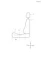
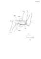
図1は、本発明に係るエアバッグ装置20L,20R(図2参照)を搭載可能な車両用シートの主に外観形状を示す斜視図である。図2は、図1に示す車両用シートの骨組みとして機能する内部構造体(シートフレーム)を示す斜視図である。図3は、本発明に係るエアバッグ装置20L,20Rを搭載した車両用シートの概略側面図であり、車幅方向の外側から透視した様子を概略的に示す。Figure 1 is a perspective view mainly showing the external shape of a vehicle seat on which the
図1及び図2に示すように、車両用シートは、部位として観たときには、乗員が着座する部分のシートクッション2と、背もたれを形成するシートバック1と、シートバック1の上端に連結されるヘッドレスト3とによって構成されている。シートバック1は、乗員の背中が接する背面1aと、サイドサポート12とを含む。As shown in Figures 1 and 2, a vehicle seat, when viewed as a set of parts, is composed of a
図2に示すように、シートバック1の内部にはシートの骨格を形成するシートバックフレーム1fが設けられ、その表面及び周囲にはウレタン発泡材等からなるパッド(図示せず)が設けられ、当該パッドの表面は皮革、ファブリック等の表皮によって覆われている。シートクッション2の底側には着座フレーム2fが配置され、シートバック1と同様に、その上面及び周囲にはウレタン発泡材等からなるパッドが設けられ、当該パッドの表面は皮革、ファブリック等の表皮によって覆われている。着座フレーム2fとシートバックフレーム1fとは、リクライニング機構4を介して連結されている。As shown in FIG. 2, a seat back
シートバックフレーム1fは、図2に示すように、左右に離間して配置され上下方向に延在するサイドフレーム10と、このサイドフレーム10の上端部を連結する上部フレームと、下端部を連結する下部フレームとにより枠状に構成されている。ヘッドレストフレームの外側にクッション部材を設けることでヘッドレスト3が構成される。As shown in FIG. 2, the
図2及び図3に示すように、左右2つのエアバッグモジュール20L,20Rが、シートクッション2の内部で、左右の縁部付近に配置、固定される。As shown in Figures 2 and 3, two
(第1実施例)
図4は、本発明の第1実施例に係るエアバッグ装置の展開の様子を概略的に示す模式図である。図5は、本発明の第1実施例に係るエアバッグ装置20L,20Rの収容状態を概略的に示すものであり、(A)が上面模式図(俯瞰図)、(B)が正面模式図、(C)が左側面模式図である。また、図6はエアバッグ装置20L,20Rの展開状態を概略的に示すものであり、(A)が上面模式図(俯瞰図)、(B)が正面模式図、(C)が左側面模式図である。(First embodiment)
Fig. 4 is a schematic diagram showing the deployment of the airbag device according to the first embodiment of the present invention. Fig. 5 is a schematic diagram showing the stored state of the
本実施例に係るエアバッグ装置は、車両用シートの座面下部に収容されるものであり、シートクッション2の左右に配置され、各々独立して動作可能な左側エアバッグモジュール20Lと、右側エアバッグモジュール20Rとを備えている。左側エアバッグモジュール20Lと右側エアバッグモジュール20Rの各々は、膨張展開することで乗員を拘束するエアバッグ(20La,20Lb,20Ra,20Rb)と、これらのエアバッグ(20La,20Lb,20Ra,20Rb)に対して膨張ガスを供給するインフレータ(22L,22R)とを備えている。エアバッグ(20La,20Lb,20Ra,20Rb)は、乗員の大腿部の下で膨張展開する下部チャンバ20La,20Raと、乗員の大腿部の外側部で膨張展開する側部チャンバ20Lb,20Rbとを含む。The airbag device according to this embodiment is housed under the seat of a vehicle seat and includes a
図4、図5(A)、図6(A)に示すように、下部チャンバ20La、20Raは、シートクッション2の前後方向の中心X1よりも前方に偏って膨張展開する。ここで、「前方に偏って」とは、下部チャンバ20La,20Raの前後方向の中心が座面中心X1よりも前方に位置する状態を意味し、必ずしも下部チャンバ20La,20Raの全体が座面中心X1よりも前方に位置する必要はない。As shown in Figures 4, 5(A), and 6(A), the lower chambers 20La, 20Ra inflate and deploy biased forward from the center X1 in the front-to-rear direction of the
下部チャンバ20La,20Raをシートクッション2の前方寄りに配置することにより、当該チャンバ20La,20Raが膨張展開した時に、シートクッション2の前方部分が上昇し、乗員の膝が持ち上がるような格好となる。これによって、乗員の前方移動を効果的に抑制することが可能となる。By locating the lower chambers 20La, 20Ra toward the front of the
図4、図6(B),(C)に示すように、側部チャンバ20Lb,20Rbが膨張した時には、当該チャンバの上端部が、上下方向における乗員の大腿部の中心位置X2よりも上方に位置するように構成される。これによって、乗員の大腿部を側面から確実に拘束することが可能となる。As shown in Figures 4, 6 (B) and (C), when the side chambers 20Lb and 20Rb are inflated, the upper ends of the chambers are configured to be positioned above the center position X2 of the occupant's thighs in the vertical direction. This makes it possible to reliably restrain the occupant's thighs from the sides.
図7は、第1実施例に係るエアバッグ装置に使用されるエアバッグの構造を示すものであり、(A)が圧縮前の状態、(B)が圧縮後の状態、(C)が展開時の状態を示す。なお、便宜上、左側エアバッグモジュール20Lについて説明するが、右側エアバッグモジュール20Rも同様の構成である。Figure 7 shows the structure of the airbag used in the airbag device of the first embodiment, with (A) showing the state before compression, (B) showing the state after compression, and (C) showing the state when deployed. For convenience, the
図7(A)に示すように、インフレータ22Lが下部チャンバ20Laの内部で、外側縁部付近に配置される。インフレータ22Lは、筒状タイプを使用することができ、前後方向に概ね平行に延びるように配置することができる。As shown in FIG. 7(A), the
図7(B)に示すように、エアバッグを圧縮する際には、下部チャンバ20Laと側部チャンバ20Lbを、互いの連結部に向かって蛇腹折りや、ロールする。なお、エアバッグの圧縮方法は、蛇腹折り、ロールの一方又は、両方を組み合わせて行うこともできる。As shown in FIG. 7B, when compressing the airbag, the lower chamber 20La and the side chamber 20Lb are folded or rolled toward their connecting parts. The airbag can also be compressed by folding or rolling the airbag or by combining both methods.
インフレータ22Lの位置については、図7(A)に示す位置に限らず、他の位置とすることも可能である。The position of the
図8は、本発明の第1実施例に係るエアバッグ装置の動作を示す正面模式図であり、(A)がエアバッグ展開前(収容時)の状態、(B)が展開時の状態を示す。Figure 8 is a front view showing the operation of the airbag device according to the first embodiment of the present invention, where (A) shows the state before the airbag is deployed (when stored) and (B) shows the state after deployment.
図8(A)に示すような衝突前の状態から、左からの側面衝突が発生すると、同図(B)に示すように、左側エアバッグモジュール20Lのみを起動する。これにより、下部チャンバ20Laと側部チャンバ20Lbが展開する。When a side collision occurs from the left in the pre-crash state shown in FIG. 8(A), only the
車両の左側からの側面衝突が発生したときは、乗員Pは慣性によってシートに対して左方向に移動しようとするが、その左方向への移動を左側エアバッグモジュール20Lの側部チャンバ20Lbによって規制することができる。また、下部チャンバ20Laによって座面の左側のみが持ち上がるため、座面の左側が右側よりも高くなり、乗員Pが左側に移動する際の抵抗となり、左方向への移動を効果的に抑制することができる。なお、右側からの側面衝突の場合も同様である。When a side collision occurs from the left side of the vehicle, the occupant P will tend to move leftward relative to the seat due to inertia, but this movement to the left can be restricted by the side chamber 20Lb of the
本実施例においては、側部チャンバ20Lb,20Rbが膨張展開する際には、シートクッション2の該当箇所が開裂する。クッションの開裂の仕方については、周知のサイドエアバッグの場合と同様とすることができる。一方、下部チャンバ20La、20Raについては、シートクッション2の内部で膨張展開し、外部に露出しない構成を基本とするが、側部チャンバ20Lb,20Rbと同様に、シートクッション2を開裂して外部に露出する構成とすることも可能である。In this embodiment, when the side chambers 20Lb, 20Rb inflate and deploy, the corresponding portions of the
図9は、本発明の第1実施例に係るエアバッグ装置の正面衝突発生時の動作を示す正面模式図であり、(A)がエアバッグ展開前(収容時)の状態、(B)が展開時の状態を示す。 図10は、本発明の第1実施例に係るエアバッグ装置の側面衝突発生時の動作を示す正面模式図であり、(A)が右側面からの衝突時のエアバッグの展開状態、(B)が左側面からの衝突時のエアバッグの展開状態を示す。Figure 9 is a schematic front view showing the operation of the airbag device according to the first embodiment of the present invention in a frontal collision, where (A) shows the state before the airbag is deployed (when stored) and (B) shows the state after deployment. Figure 10 is a schematic front view showing the operation of the airbag device according to the first embodiment of the present invention in a side collision, where (A) shows the deployed state of the airbag in a right side collision and (B) shows the deployed state of the airbag in a left side collision.
図9(A)に示す初期状態(衝突発生前)から、車両の正面衝突が発生したときは、同図(B)に示すように、左側エアバッグモジュール20Lと右側エアバッグモジュール20Rの両方が起動する。When a head-on collision occurs in the initial state (before a collision occurs) shown in FIG. 9(A), both the
左右両方のエアバッグモジュール20L,20Rを起動することによって、乗員の左右両方の大腿部の前方部分が持ち上がり、乗員の腰部が前方にスライドするのを効果的に抑制することができる。By activating both the left and
図10(A)に示すように、車両の右側からの側面衝突が発生したときは、右側エアバッグモジュール20Rのみを起動する。同様に、車両の左側からの側面衝突が発生したときは、図10(B)に示すように、左側エアバッグモジュール20Lのみを起動する。
(効果) As shown in Fig. 10A, when a side collision occurs from the right side of the vehicle, only the
(effect)
本発明においては、エアバッグが大腿部の下で膨張展開する下部チャンバ20La,20Raと、大腿部の外側部で膨張展開する側部チャンバ20Lb,20Rbとを備えているため、下部チャンバ20La,20Raによって乗員の前方への移動が拘束され、所謂サブマリン現象を回避することが可能となる。更に、側部チャンバ20Lb,20Rbによって乗員の横方向の移動を拘束することができ、側面衝突の際の乗員保護性能が向上することになる。In the present invention, the airbag is provided with lower chambers 20La, 20Ra that inflate and deploy under the thighs, and side chambers 20Lb, 20Rb that inflate and deploy on the outer sides of the thighs, so that the lower chambers 20La, 20Ra restrain the occupant from moving forward, making it possible to avoid the so-called submarine phenomenon. Furthermore, the side chambers 20Lb, 20Rb can restrain the occupant from moving laterally, improving occupant protection performance in the event of a side collision.
(2段階展開)
以下、エアバッグ装置を2段階で起動する方法について説明する。すなわち、衝突の側(ニアサイド)のエアバッグモジュールを最初に起動する一次展開を行い、続いて、当該衝突と反対側(ファーサイド)のエアバッグモジュールを起動する二次展開を行う方法について説明する。(Two-stage deployment)
Hereinafter, a method of activating an airbag device in two stages will be described, that is, a primary deployment method in which the airbag module on the side of the collision (near side) is first activated, and then a secondary deployment method in which the airbag module on the opposite side of the collision (far side) is activated.
図11は、本発明の第1実施例に係るエアバッグ装置の右側面衝突発生時の動作を示す正面模式図であり、(A)が一次展開の様子、(B)が二次展開の様子を示す。Figure 11 is a front view showing the operation of the airbag device according to the first embodiment of the present invention in the event of a right side collision, where (A) shows the primary deployment and (B) shows the secondary deployment.
図11(A)に示すように、車両の右側からの側面衝突が発生したときは、右側エアバッグモジュール20Rのみを起動する(一次展開)。車両の右側から側面衝突が発生した直後は、図11(A)に示すように、乗員は右側に移動するので、その乗員PR、PLを右側エアバッグモジュール20Rによって拘束する。その後、乗員は反動で左側に振り戻される(リバウンドする)ことになる。As shown in FIG. 11(A), when a side collision occurs from the right side of the vehicle, only the
そこで、図11(B)に示すように、右側エアバッグモジュール20Rの起動から若干遅れて左側エアバッグモジュール20Lを起動する(二次展開)。左側に振り戻された乗員PRの右方向への移動が拘束され、左隣席の他の乗員PLとの接触を回避することが可能となる。なお、左側からの側面衝突の場合も、左右が逆になるだけで同様となる。As shown in FIG. 11(B), the
図12は、本発明の第1実施例に係るエアバッグ装置の右側面衝突発生時の動作を示す正面模式図であり、図11の態様と異なる態様であり、(A)が一次展開の様子、(B)が二次展開の様子を示す。Figure 12 is a front view showing the operation of the airbag device according to the first embodiment of the present invention in the event of a right side collision, which is different from the state shown in Figure 11, with (A) showing the primary deployment and (B) showing the secondary deployment.
図12示す態様と図11に示す態様との違いは、図12(B)に示されている。すなわち、二次展開の際に、衝突側(右側)に位置するシートにおいて、一次展開で起動したエアバッグモジュール20Rのガスを外部に放出することである。The difference between the embodiment shown in FIG. 12 and the embodiment shown in FIG. 11 is shown in FIG. 12(B). That is, during secondary deployment, the gas in the
右側から側面衝突が発生し、二次展開で左側エアバッグモジュール20Lを起動するタイミングで、一次展開によって膨張展開した右側エアバッグモジュール20Rのガスを排気することにより、右側エアバッグモジュール20Rが萎むことになる。そのため、右側の座席では、シートクッションの右側に比べて左側が高くなり、乗員PRが左側にスライドし難くなる。なお、左側からの側面衝突の場合も同様である。When a side collision occurs from the right side and the
(パネル構成)
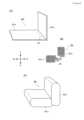
図13は、本発明の第1実施例に係るエアバッグ装置のエアバッグを構成するパネル構成を示す平面図(A)と、実際に膨張展開した様子を示す斜視図(B)である。なお、便宜上、左側エアバッグモジュール20Lについてのみ説明するが、右側エアバッグモジュール20Rについても構成的には同一である。また、インフレータ22Lについては、図示を省略する。(Panel composition)
13A is a plan view showing the panel configuration constituting the airbag of the airbag device according to the first embodiment of the present invention, and FIG. 13B is a perspective view showing the state of the airbag actually inflated and deployed. For convenience, only the
図13(A)に示すように、下部チャンバ20Laは、1枚の長方形の布製パネル50の周囲を縫製することによって袋状に成形される。また、側部チャンバ20Lbは、1枚の長方形の布製パネル52の周囲を縫製することによって袋状に成形される。パネル50には複数(例えば、4個)の円形の内部ベント50aが形成され、パネル52には複数(例えば、4個)の円形の内部ベント52aが形成されている。そして、これらの内部ベント50a,52aの周囲同士を縫製することによって、図13(B)に示すように断面L字状のエアバッグが成形される。As shown in FIG. 13(A), the lower chamber 20La is formed into a bag shape by sewing the periphery of a
左側エアバッグモジュール20Lが起動すると、インフレータ22Lから放出された膨張ガスが、下部チャンバ20Laから、内部ベント50a,52aを介して側部チャンバ20Lbに流入することになる。When the
図14は、本発明の第1実施例に係るエアバッグ装置のエアバッグを構成する他のパネル構成を示す平面図(A)と、実際に膨張展開した様子を示す斜視図(B)である。なお、便宜上、左側エアバッグモジュール20Lについてのみ説明するが、右側エアバッグモジュール20Rについても構成的には同一である。Figure 14 shows (A) a plan view showing another panel configuration constituting the airbag of the airbag device according to the first embodiment of the present invention, and (B) a perspective view showing the actual inflated and deployed state. For convenience, only the
図14(A)に示すように、下部チャンバ20La及び側部チャンバ20Lbは、1枚の長方形の布製パネル60と、L字状の2枚の前後パネル62a,62bと、仕切りパネル64とによって成形される。パネル60の長手方向両端部を縫製することによって筒状に成形し、開放端部に前後パネル62a,62bを縫製によって連結することによって、図14(B)に示すように断面L字状のエアバッグが成形される。As shown in FIG. 14(A), the lower chamber 20La and the side chamber 20Lb are formed from one
前後パネル62a,62bの角部(屈曲部)には、前後方向に延びる仕切りパネル64が縫製によって連結される。仕切りパネル64には、下部チャンバ20Laと側部チャンバ20Lbとを流体的に連通させる内部ベント64aが形成されている。A
左側エアバッグモジュール20Lが起動すると、インフレータ22Lから放出された膨張ガスが、下部チャンバ20Laから、仕切りパネル64の内部ベント64aを介して側部チャンバ20Lbに流入することになる。When the
(第2実施例)
図15は、本発明の第2実施例に係るエアバッグ装置の展開の様子を概略的に示す模式図である。なお、便宜上シートの左側に配置される左側エアバッグモジュール120Lを例にとって説明するが、実際には、第1実施例と同様にシートクッション2の左右両側にエアバッグモジュールが装備される(図5等参照)。Second Example
15 is a schematic diagram showing the deployment of an airbag device according to a second embodiment of the present invention. For convenience, the
本実施例に係るエアバッグモジュール(120L)と第1実施例に係るエアバッグモジュール20Lを比較すると、下部チャンバ20La、120Laは同一の構造であるが、側部チャンバ20Lb,120Lbの形状に相違がある。本実施例に係る側部チャンバ120Lbは、下部チャンバ120Laの後端部よりも後方に延びる延長チャンバ部分170を有している。側部チャンバ120Lbが後方に延びて展開することにより、乗員の側方への移動を効果的に拘束することが可能となる。Comparing the airbag module (120L) of this embodiment with the
(パネル構成)
図16は、本発明の第2実施例に係るエアバッグ装置のエアバッグを構成するパネル構成を示す平面図(A)と、実際に膨張展開した様子を示す斜視図(B)である。なお、便宜上、左側エアバッグモジュール120Lについてのみ説明するが、右側エアバッグモジュールについても構成的には同一である。また、インフレータについては、図示を省略する。このパネル構成は、図13に示した第1実施例のパネル構成をアレンジしたものである。(Panel composition)
16A is a plan view showing the panel configuration constituting the airbag of the airbag device according to the second embodiment of the present invention, and FIG. 16B is a perspective view showing the state of the airbag actually inflated and deployed. For convenience, only the
図16(A)に示すように、下部チャンバ120Laは、1枚の長方形の布製パネル150の周囲を縫製することによって袋状に成形される。また、側部チャンバ120Lbは、1枚の布製パネル152の周囲を縫製することによって袋状に成形される。パネル150には複数(例えば、4個)の円形の内部ベント150aが形成され、パネル152には複数(例えば、4個)の円形の内部ベント152aが形成されている。そして、これらの内部ベント150a,152aの周囲同士を縫製することによって、図16(B)に示すように断面L字状のエアバッグが成形される。As shown in FIG. 16(A), the lower chamber 120La is formed into a bag shape by sewing the periphery of a single
パネル154には、一対の突出部154が形成されており、これら突出部154の周囲を縫製することによって、延長チャンバ部分170が成形されることになる。The
左側エアバッグモジュール120Lが起動すると、インフレータから放出された膨張ガスが、下部チャンバ120Laから、内部ベント150a,152aを介して側部チャンバ120Lbに流入することになる。When the
図17は、本発明の第2実施例に係るエアバッグ装置のエアバッグを構成する他のパネル構成を示す平面図(A)と、実際に膨張展開した様子を示す斜視図(B)である。なお、便宜上、左側エアバッグモジュール120Lについてのみ説明するが、右側エアバッグモジュール120Rについても構成的には同一である。また、インフレータについては、図示を省略する。このパネル構成は、図14に示した第1実施例のパネル構成をアレンジしたものである。Figure 17 shows (A) a plan view showing another panel configuration constituting the airbag of an airbag device according to a second embodiment of the present invention, and (B) a perspective view showing the actual inflated and deployed state. For convenience, only the
図17(A)に示すように、下部チャンバ120La及び側部チャンバ120Lbは、1枚の布製パネル260と、L字状の2枚の前後パネル262a,262bと、仕切りパネル264とによって成形される。パネル260の長手方向両端部を縫製することによって筒状に成形し、開放端部に前後パネル262a,262bを縫製によって連結することによって、図17(B)に示すように断面L字状のエアバッグが成形される。As shown in FIG. 17(A), the lower chamber 120La and the side chamber 120Lb are formed by one
L字状の2枚の前後パネル262a,262bの一方262bは、他方のパネル262aよりも縦方向に長く延びた延長部分263を備えた形状となっている。また、パネル260の端部には一対の突出部254が形成されており、これら突出部254と、パネル262bの延長部分263とを縫製によって連結することで、延長チャンバ部分170が成形されることになる。One 262b of the two L-shaped front and
前後パネル262a,262bの角部(屈曲部)には、前後方向に延びる仕切りパネル264が縫製によって連結される。仕切りパネル264には、下部チャンバ120Laと側部チャンバ120Lbとを流体的に連通させる内部ベント264aが形成されている。A
左側エアバッグモジュール120Lが起動すると、インフレータから放出された膨張ガスが、下部チャンバ120Laから、仕切りパネル264の内部ベント264aを介して側部チャンバ120Lbに流入することになる。When the
本発明について実施例を参照して説明したが、本発明はこれらの実施例に何ら限定されるものではなく、本発明の技術的思想の範囲内において適宜変更可能なものである。The present invention has been described with reference to examples, but the present invention is not limited to these examples and can be modified as appropriate within the scope of the technical concept of the present invention.
Claims (14)
Translated fromJapanese当該エアバッグ装置は、シートの座面の左右に配置され、各々独立して動作可能な左側エアバッグモジュールと、右側エアバッグモジュールとを含み、
前記左側エアバッグモジュールと前記右側エアバッグモジュールの各々は、膨張展開することで乗員を拘束するエアバッグと、前記エアバッグに対して膨張ガスを供給するガス発生器とを含み、
前記エアバッグは、乗員の大腿部の下で膨張展開する下部チャンバと、乗員の大腿部の外側部で膨張展開する側部チャンバとを含み、
車両の側面衝突が発生したときは、当該衝突の側(ニアサイド)のエアバッグモジュールを起動する一次展開を行い、続いて、当該衝突と反対側(ファーサイド)のエアバッグモジュールを起動する二次展開を行うことを特徴とするエアバッグ装置。 An airbag device accommodated under a seat cushion of a vehicle seat,
The airbag device includes a left airbag module and a right airbag module that are disposed on the left and right sides of a seat surface and are independently operable,
Each of the left airbag module and the right airbag module includes an airbag that inflates and deploys to restrain an occupant, and a gas generator that supplies inflation gas to the airbag,
The airbagincludes a lower chamber that inflates and deploys under the thighs of an occupant, and a side chamber that inflates and deploys on the outer sides of the thighs of the occupant,
This airbag device is characterized in that, when a side collision of a vehicle occurs, a primary deployment is performed to activate an airbag module on the side of the collision (near side), followed by a secondary deployment to activate an airbag module on the opposite side of the collision (far side) .
車両の右側からの側面衝突が発生したときは、前記右側エアバッグモジュールを起動することを特徴とする請求項1又は2に記載のエアバッグ装置。 When a side collision occurs from the left side of the vehicle, the left airbag module is activated,
3. The airbag device according to claim 1, wherein the right airbag module is activated when a side collision occurs from the right side of the vehicle.
Priority Applications (1)
| Application Number | Priority Date | Filing Date | Title |
|---|---|---|---|
| JP2022021698AJP7519393B2 (en) | 2022-02-16 | 2022-02-16 | Seat-mounted airbag device |
Applications Claiming Priority (1)
| Application Number | Priority Date | Filing Date | Title |
|---|---|---|---|
| JP2022021698AJP7519393B2 (en) | 2022-02-16 | 2022-02-16 | Seat-mounted airbag device |
Publications (2)
| Publication Number | Publication Date |
|---|---|
| JP2023119079A JP2023119079A (en) | 2023-08-28 |
| JP7519393B2true JP7519393B2 (en) | 2024-07-19 |
Family
ID=87763325
Family Applications (1)
| Application Number | Title | Priority Date | Filing Date |
|---|---|---|---|
| JP2022021698AActiveJP7519393B2 (en) | 2022-02-16 | 2022-02-16 | Seat-mounted airbag device |
Country Status (1)
| Country | Link |
|---|---|
| JP (1) | JP7519393B2 (en) |
Citations (6)
| Publication number | Priority date | Publication date | Assignee | Title |
|---|---|---|---|---|
| JP2002145003A (en) | 2000-11-15 | 2002-05-22 | Toyoda Gosei Co Ltd | Airbag system |
| US20130093224A1 (en) | 2010-03-09 | 2013-04-18 | Dainese S.P.A. | Covering assembly for a seat and seat adapted for protecting a user |
| US20190275974A1 (en) | 2018-03-12 | 2019-09-12 | Lear Corporation | Occupant protection systems for a vehicle seat |
| JP2019172149A (en) | 2018-03-29 | 2019-10-10 | 株式会社Subaru | Occupant protection device |
| US20210221316A1 (en) | 2020-01-16 | 2021-07-22 | Hyundai Mobis Co., Ltd. | Vehicular seat cushion airbag |
| US11180102B1 (en) | 2020-08-12 | 2021-11-23 | Ford Global Technologies, Llc | Side airbag assembly |
- 2022
- 2022-02-16JPJP2022021698Apatent/JP7519393B2/enactiveActive
Patent Citations (6)
| Publication number | Priority date | Publication date | Assignee | Title |
|---|---|---|---|---|
| JP2002145003A (en) | 2000-11-15 | 2002-05-22 | Toyoda Gosei Co Ltd | Airbag system |
| US20130093224A1 (en) | 2010-03-09 | 2013-04-18 | Dainese S.P.A. | Covering assembly for a seat and seat adapted for protecting a user |
| US20190275974A1 (en) | 2018-03-12 | 2019-09-12 | Lear Corporation | Occupant protection systems for a vehicle seat |
| JP2019172149A (en) | 2018-03-29 | 2019-10-10 | 株式会社Subaru | Occupant protection device |
| US20210221316A1 (en) | 2020-01-16 | 2021-07-22 | Hyundai Mobis Co., Ltd. | Vehicular seat cushion airbag |
| US11180102B1 (en) | 2020-08-12 | 2021-11-23 | Ford Global Technologies, Llc | Side airbag assembly |
Also Published As
| Publication number | Publication date |
|---|---|
| JP2023119079A (en) | 2023-08-28 |
Similar Documents
| Publication | Publication Date | Title |
|---|---|---|
| KR102064844B1 (en) | Airbag apparatus of vehicle | |
| US12337784B2 (en) | Airbag device and vehicle seat | |
| US11752966B2 (en) | Side airbag device | |
| US11752965B2 (en) | Side airbag device and method for manufacturing side airbag device | |
| JP7722318B2 (en) | Airbag devices and occupant protection devices | |
| CN116194344A (en) | Airbag device | |
| JP7078742B2 (en) | Vehicle seat | |
| CN111086478A (en) | Side airbag device | |
| US20200346604A1 (en) | Side airbag apparatus and vehicle seat including the same | |
| KR102729838B1 (en) | Airbag devices and vehicle seats | |
| JP7381772B2 (en) | Seat built-in airbag device | |
| JP7555477B2 (en) | Airbag device | |
| JP7519393B2 (en) | Seat-mounted airbag device | |
| WO2024095697A1 (en) | Occupant restraint apparatus | |
| KR102408036B1 (en) | Airbag apparatus | |
| WO2021166530A1 (en) | Side airbag device | |
| JP7671868B2 (en) | Airbag device | |
| JP7514307B2 (en) | Airbag device | |
| JP2020059334A (en) | Vehicular seat | |
| JP2023046992A (en) | Airbag device and passenger vehicle provided with airbag device | |
| WO2025216141A1 (en) | Occupant protection device | |
| KR20240124126A (en) | Side airbag apparatus for vihicle |
Legal Events
| Date | Code | Title | Description |
|---|---|---|---|
| A621 | Written request for application examination | Free format text:JAPANESE INTERMEDIATE CODE: A621 Effective date:20230830 | |
| RD03 | Notification of appointment of power of attorney | Free format text:JAPANESE INTERMEDIATE CODE: A7423 Effective date:20231122 | |
| A131 | Notification of reasons for refusal | Free format text:JAPANESE INTERMEDIATE CODE: A131 Effective date:20240319 | |
| A977 | Report on retrieval | Free format text:JAPANESE INTERMEDIATE CODE: A971007 Effective date:20240322 | |
| A521 | Request for written amendment filed | Free format text:JAPANESE INTERMEDIATE CODE: A523 Effective date:20240419 | |
| TRDD | Decision of grant or rejection written | ||
| A01 | Written decision to grant a patent or to grant a registration (utility model) | Free format text:JAPANESE INTERMEDIATE CODE: A01 Effective date:20240702 | |
| A61 | First payment of annual fees (during grant procedure) | Free format text:JAPANESE INTERMEDIATE CODE: A61 Effective date:20240708 | |
| R150 | Certificate of patent or registration of utility model | Ref document number:7519393 Country of ref document:JP Free format text:JAPANESE INTERMEDIATE CODE: R150 |