JP7514704B2 - X-ray tube holding device and X-ray imaging system - Google Patents
X-ray tube holding device and X-ray imaging systemDownload PDFInfo
- Publication number
- JP7514704B2 JP7514704B2JP2020147029AJP2020147029AJP7514704B2JP 7514704 B2JP7514704 B2JP 7514704B2JP 2020147029 AJP2020147029 AJP 2020147029AJP 2020147029 AJP2020147029 AJP 2020147029AJP 7514704 B2JP7514704 B2JP 7514704B2
- Authority
- JP
- Japan
- Prior art keywords
- ray tube
- ray
- imaging system
- holding device
- tube holding
- Prior art date
- Legal status (The legal status is an assumption and is not a legal conclusion. Google has not performed a legal analysis and makes no representation as to the accuracy of the status listed.)
- Active
Links
Images


Classifications
- A—HUMAN NECESSITIES
- A61—MEDICAL OR VETERINARY SCIENCE; HYGIENE
- A61B—DIAGNOSIS; SURGERY; IDENTIFICATION
- A61B6/00—Apparatus or devices for radiation diagnosis; Apparatus or devices for radiation diagnosis combined with radiation therapy equipment
- A61B6/44—Constructional features of apparatus for radiation diagnosis
- A61B6/4405—Constructional features of apparatus for radiation diagnosis the apparatus being movable or portable, e.g. handheld or mounted on a trolley
- A—HUMAN NECESSITIES
- A61—MEDICAL OR VETERINARY SCIENCE; HYGIENE
- A61B—DIAGNOSIS; SURGERY; IDENTIFICATION
- A61B6/00—Apparatus or devices for radiation diagnosis; Apparatus or devices for radiation diagnosis combined with radiation therapy equipment
- A61B6/44—Constructional features of apparatus for radiation diagnosis
- A—HUMAN NECESSITIES
- A61—MEDICAL OR VETERINARY SCIENCE; HYGIENE
- A61B—DIAGNOSIS; SURGERY; IDENTIFICATION
- A61B6/00—Apparatus or devices for radiation diagnosis; Apparatus or devices for radiation diagnosis combined with radiation therapy equipment
- A61B6/42—Arrangements for detecting radiation specially adapted for radiation diagnosis
- A61B6/4208—Arrangements for detecting radiation specially adapted for radiation diagnosis characterised by using a particular type of detector
- A—HUMAN NECESSITIES
- A61—MEDICAL OR VETERINARY SCIENCE; HYGIENE
- A61B—DIAGNOSIS; SURGERY; IDENTIFICATION
- A61B6/00—Apparatus or devices for radiation diagnosis; Apparatus or devices for radiation diagnosis combined with radiation therapy equipment
- A61B6/44—Constructional features of apparatus for radiation diagnosis
- A61B6/4429—Constructional features of apparatus for radiation diagnosis related to the mounting of source units and detector units
- A61B6/4452—Constructional features of apparatus for radiation diagnosis related to the mounting of source units and detector units the source unit and the detector unit being able to move relative to each other
- A—HUMAN NECESSITIES
- A61—MEDICAL OR VETERINARY SCIENCE; HYGIENE
- A61B—DIAGNOSIS; SURGERY; IDENTIFICATION
- A61B6/00—Apparatus or devices for radiation diagnosis; Apparatus or devices for radiation diagnosis combined with radiation therapy equipment
- A61B6/54—Control of apparatus or devices for radiation diagnosis
- A61B6/548—Remote control of the apparatus or devices
- B—PERFORMING OPERATIONS; TRANSPORTING
- B64—AIRCRAFT; AVIATION; COSMONAUTICS
- B64C—AEROPLANES; HELICOPTERS
- B64C39/00—Aircraft not otherwise provided for
- B64C39/02—Aircraft not otherwise provided for characterised by special use
- B64C39/024—Aircraft not otherwise provided for characterised by special use of the remote controlled vehicle type, i.e. RPV
- B—PERFORMING OPERATIONS; TRANSPORTING
- B64—AIRCRAFT; AVIATION; COSMONAUTICS
- B64U—UNMANNED AERIAL VEHICLES [UAV]; EQUIPMENT THEREFOR
- B64U20/00—Constructional aspects of UAVs
- B64U20/80—Arrangement of on-board electronics, e.g. avionics systems or wiring
- B64U20/87—Mounting of imaging devices, e.g. mounting of gimbals
- G—PHYSICS
- G05—CONTROLLING; REGULATING
- G05D—SYSTEMS FOR CONTROLLING OR REGULATING NON-ELECTRIC VARIABLES
- G05D1/00—Control of position, course, altitude or attitude of land, water, air or space vehicles, e.g. using automatic pilots
- G05D1/0094—Control of position, course, altitude or attitude of land, water, air or space vehicles, e.g. using automatic pilots involving pointing a payload, e.g. camera, weapon, sensor, towards a fixed or moving target
- G—PHYSICS
- G05—CONTROLLING; REGULATING
- G05D—SYSTEMS FOR CONTROLLING OR REGULATING NON-ELECTRIC VARIABLES
- G05D1/00—Control of position, course, altitude or attitude of land, water, air or space vehicles, e.g. using automatic pilots
- G05D1/10—Simultaneous control of position or course in three dimensions
- G05D1/101—Simultaneous control of position or course in three dimensions specially adapted for aircraft
- G05D1/106—Change initiated in response to external conditions, e.g. avoidance of elevated terrain or of no-fly zones
- G—PHYSICS
- G05—CONTROLLING; REGULATING
- G05D—SYSTEMS FOR CONTROLLING OR REGULATING NON-ELECTRIC VARIABLES
- G05D1/00—Control of position, course, altitude or attitude of land, water, air or space vehicles, e.g. using automatic pilots
- G05D1/60—Intended control result
- G05D1/606—Compensating for or utilising external environmental conditions, e.g. wind or water currents
- G—PHYSICS
- G05—CONTROLLING; REGULATING
- G05D—SYSTEMS FOR CONTROLLING OR REGULATING NON-ELECTRIC VARIABLES
- G05D1/00—Control of position, course, altitude or attitude of land, water, air or space vehicles, e.g. using automatic pilots
- G05D1/60—Intended control result
- G05D1/656—Interaction with payloads or external entities
- G05D1/689—Pointing payloads towards fixed or moving targets
- H—ELECTRICITY
- H05—ELECTRIC TECHNIQUES NOT OTHERWISE PROVIDED FOR
- H05G—X-RAY TECHNIQUE
- H05G1/00—X-ray apparatus involving X-ray tubes; Circuits therefor
- H05G1/08—Electrical details
- H05G1/10—Power supply arrangements for feeding the X-ray tube
- H—ELECTRICITY
- H05—ELECTRIC TECHNIQUES NOT OTHERWISE PROVIDED FOR
- H05G—X-RAY TECHNIQUE
- H05G1/00—X-ray apparatus involving X-ray tubes; Circuits therefor
- H05G1/08—Electrical details
- H05G1/26—Measuring, controlling or protecting
- H05G1/30—Controlling
- A—HUMAN NECESSITIES
- A61—MEDICAL OR VETERINARY SCIENCE; HYGIENE
- A61B—DIAGNOSIS; SURGERY; IDENTIFICATION
- A61B6/00—Apparatus or devices for radiation diagnosis; Apparatus or devices for radiation diagnosis combined with radiation therapy equipment
- A61B6/02—Arrangements for diagnosis sequentially in different planes; Stereoscopic radiation diagnosis
- A61B6/025—Tomosynthesis
- A—HUMAN NECESSITIES
- A61—MEDICAL OR VETERINARY SCIENCE; HYGIENE
- A61B—DIAGNOSIS; SURGERY; IDENTIFICATION
- A61B6/00—Apparatus or devices for radiation diagnosis; Apparatus or devices for radiation diagnosis combined with radiation therapy equipment
- A61B6/58—Testing, adjusting or calibrating thereof
- A61B6/588—Setting distance between source unit and detector unit
- B—PERFORMING OPERATIONS; TRANSPORTING
- B64—AIRCRAFT; AVIATION; COSMONAUTICS
- B64U—UNMANNED AERIAL VEHICLES [UAV]; EQUIPMENT THEREFOR
- B64U10/00—Type of UAV
- B64U10/10—Rotorcrafts
- B64U10/13—Flying platforms
- B—PERFORMING OPERATIONS; TRANSPORTING
- B64—AIRCRAFT; AVIATION; COSMONAUTICS
- B64U—UNMANNED AERIAL VEHICLES [UAV]; EQUIPMENT THEREFOR
- B64U10/00—Type of UAV
- B64U10/10—Rotorcrafts
- B64U10/13—Flying platforms
- B64U10/14—Flying platforms with four distinct rotor axes, e.g. quadcopters
- B—PERFORMING OPERATIONS; TRANSPORTING
- B64—AIRCRAFT; AVIATION; COSMONAUTICS
- B64U—UNMANNED AERIAL VEHICLES [UAV]; EQUIPMENT THEREFOR
- B64U2101/00—UAVs specially adapted for particular uses or applications
- B—PERFORMING OPERATIONS; TRANSPORTING
- B64—AIRCRAFT; AVIATION; COSMONAUTICS
- B64U—UNMANNED AERIAL VEHICLES [UAV]; EQUIPMENT THEREFOR
- B64U2101/00—UAVs specially adapted for particular uses or applications
- B64U2101/30—UAVs specially adapted for particular uses or applications for imaging, photography or videography
- B—PERFORMING OPERATIONS; TRANSPORTING
- B64—AIRCRAFT; AVIATION; COSMONAUTICS
- B64U—UNMANNED AERIAL VEHICLES [UAV]; EQUIPMENT THEREFOR
- B64U2201/00—UAVs characterised by their flight controls
- B64U2201/10—UAVs characterised by their flight controls autonomous, i.e. by navigating independently from ground or air stations, e.g. by using inertial navigation systems [INS]
- B64U2201/104—UAVs characterised by their flight controls autonomous, i.e. by navigating independently from ground or air stations, e.g. by using inertial navigation systems [INS] using satellite radio beacon positioning systems, e.g. GPS
Landscapes
- Engineering & Computer Science (AREA)
- Health & Medical Sciences (AREA)
- Life Sciences & Earth Sciences (AREA)
- Medical Informatics (AREA)
- Physics & Mathematics (AREA)
- Aviation & Aerospace Engineering (AREA)
- General Health & Medical Sciences (AREA)
- Heart & Thoracic Surgery (AREA)
- Pathology (AREA)
- Veterinary Medicine (AREA)
- Public Health (AREA)
- Animal Behavior & Ethology (AREA)
- Surgery (AREA)
- Biophysics (AREA)
- High Energy & Nuclear Physics (AREA)
- Remote Sensing (AREA)
- Nuclear Medicine, Radiotherapy & Molecular Imaging (AREA)
- Optics & Photonics (AREA)
- Molecular Biology (AREA)
- Radiology & Medical Imaging (AREA)
- Biomedical Technology (AREA)
- Radar, Positioning & Navigation (AREA)
- General Physics & Mathematics (AREA)
- Automation & Control Theory (AREA)
- Mechanical Engineering (AREA)
- Microelectronics & Electronic Packaging (AREA)
- Toxicology (AREA)
- Apparatus For Radiation Diagnosis (AREA)
- X-Ray Techniques (AREA)
Description
Translated fromJapanese本明細書及び図面に開示の実施形態は、X線管保持装置及びX線撮影システムに関する。The embodiments disclosed in this specification and the drawings relate to an X-ray tube holding device and an X-ray imaging system.
従来、非破壊検査等の工業分野や、健康診断等の医療分野において、被検体の検査部位(例えば、胸部)に放射線(代表的には、X線)を照射して、検査部位を透過したX線の強度分布を透過データとして検出し、透過データからX線画像データを生成するX線撮影システムが広く利用されている。X線撮影システムは、X線照射を行って透過データを取得し、透過データに対する画像処理等を行ってX線画像データを生成することができる。Conventionally, in industrial fields such as non-destructive testing, and in medical fields such as health checkups, X-ray imaging systems have been widely used that irradiate an examination area (e.g., the chest) of a subject with radiation (typically, X-rays), detect the intensity distribution of the X-rays that have passed through the examination area as transmission data, and generate X-ray image data from the transmission data. X-ray imaging systems can irradiate X-rays to obtain transmission data, and perform image processing, etc. on the transmission data to generate X-ray image data.
X線撮影システムにおいて、胸部や頸椎のX線撮影において診断に有用なX線画像データを得るためには、焦点検出器間距離(SID:Source to image receptor distance)が特に重要となる。しかし、従来のX線撮影システムでは、X線管やX線検出器等の配置に制限から、所望のSIDに係るX線画像データを取得することができない場合がある。In X-ray imaging systems, the source-to-image receptor distance (SID) is particularly important in order to obtain diagnostically useful X-ray image data in X-ray imaging of the chest or cervical spine. However, in conventional X-ray imaging systems, there are cases where it is not possible to obtain X-ray image data related to the desired SID due to limitations in the placement of the X-ray tube, X-ray detector, etc.
本明細書及び図面に開示の実施形態が解決しようとする課題の一つは、X線管の自由度の高い配置を実現することである。ただし、本明細書及び図面に開示の実施形態により解決しようとする課題は上記課題に限られない。後述する実施形態に示す各構成による各効果に対応する課題を他の課題として位置づけることもできる。One of the problems that the embodiments disclosed in this specification and the drawings attempt to solve is to realize a highly flexible arrangement of X-ray tubes. However, the problems that the embodiments disclosed in this specification and the drawings attempt to solve are not limited to the above problem. Problems that correspond to the effects of each configuration shown in the embodiments described below can also be positioned as other problems.
実施形態に係るX線撮影装置は、X線管と、保持機構と、飛行体部とを備える。X線管を保持する。飛行体は、保持機構を搭載する。The X-ray imaging device according to the embodiment includes an X-ray tube, a holding mechanism, and an aircraft unit. The X-ray tube is held. The aircraft unit is equipped with the holding mechanism.
以下、図面を参照しながら、X線管保持装置及びX線撮影システムの実施形態について詳細に説明する。Below, we will explain in detail the embodiments of the X-ray tube holding device and X-ray imaging system with reference to the drawings.
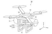
図1は、実施形態に係るX線管保持装置の構成を示す概略図である。Figure 1 is a schematic diagram showing the configuration of an X-ray tube holding device according to an embodiment.
図1は、実施形態に係るX線管保持装置10を示す。X線管保持装置10は、X線管11と、X線管11を保持する保持機構12と、保持機構12を搭載した飛行体13とを備える。Figure 1 shows an X-ray
X線管11は、高電圧電源回路37(図3に図示)から電力供給を受けて、被検体(例えば、患者)にX線を照射する。なお、X線管11の前段の開口部G付近に、可動絞り部(図示省略)が設けられる。なお、X線管11の前面に、X線管11によって発生されたX線の線質を調整する線質調整フィルタ(図示省略)が設けられてもよい。The
保持機構12は、X線管11を保持する。保持機構12は、保持本体部121と、角度変更部122とを備える。保持本体部121は、後述する飛行体13の脚部として飛行体13に接続される。また、保持本体部121は、角度変更部122を支持する。The
角度変更部122は、X線管11が円筒の体軸中心に回転可能なようにX線管11を保持する。この構成により、X線管11からのX線照射の仰俯角(以下、単に「X線管の仰俯角」という)が制御される。なお、X線管11の仰俯角を変更する角度変更部122は、保持機構12に必須の構成ではない。X線管11の仰俯角を変更する必要がない撮影の場合であって、立位撮影の場合は、X線管11の仰俯角が水平方向となるようにX線管11が保持機構12に固定されていてもよい。また、X線管11の仰俯角を変更する必要がない撮影の場合であって、臥位撮影の場合は、X線管11の仰俯角が鉛直方向となるようにX線管11が保持機構12に固定されていてもよい。The
ここで、X線管11の円筒の体軸と平行な方向をU軸と定義し、鉛直方向をV軸と定義し、U軸とV軸との直交する方向をW軸と定義する。Here, the direction parallel to the body axis of the cylinder of the
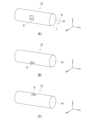
図2(A)~(C)は、X線管保持装置10に備えられるX線管11の回転を説明するための図である。Figures 2(A) to (C) are diagrams for explaining the rotation of the
図2(A)は、図1に示すX線管保持装置10から抽出されたX線管11を示す。X線管11のX線照射の位置には、開口部Gが設けられる。図2(A)の状態からX線管11が体軸AXを中心に矢印Lの向きに回転すると、図2(B)に示すように開口部Gが下方に移動する。一方で、図2(A)の状態からX線管11が体軸AXを中心に矢印Rの向きに回転すると、図2(C)に示すように開口部Gが上方に移動する。このように、角度変更部122により、保持機構12(図1に図示)に対してX線管11が体軸AXを中心に回転することで、X線管11の仰俯角を変更することができる。以下、特に言及しない場合、X線管11の仰俯角の制御を行う場合について説明する。Figure 2 (A) shows the
図1の説明に戻って、飛行体13は、操縦手の搭乗しない無人航空機を意味し、「ドローン」とも呼ばれる。飛行体13は、X線管11と保持機構12とを支持しながら、制御装置30(図3に図示)による遠隔操作(主に無線)によって飛行可能である。Returning to the explanation of FIG. 1, the
また、X線管保持装置10は、飛行体13に位置センサ14,15を備えてもよい。位置センサ14,15は、自身の位置情報をそれぞれ取得する。なお、飛行体13に設けられる位置センサは、2個である場合を例に挙げて説明するが、その場合に限定されるものではない。飛行体13に設けられる位置センサは、3個以上であってもよいし、X線管11におけるX線焦点の位置(以下、単に「X線管の位置」という)の制御のみが必要で、X線管11からの照射X線の方位角(以下、単に「X線管の方位角」という)の制御が不要である場合は、1個であってもよい。X線管11の方位角の制御が不要な場合とは、例えば、飛行体13が、飛行中にV軸中心に回転することを想定しない場合である。以下、特に言及しない場合、X線管11の位置の制御と、X線管11の方位角の制御とをともに行う場合について説明する。The X-ray
位置センサ14,15の位置情報に基づいて、X線管11の位置と、X線管11の方位角とが求められる。位置センサ14の位置と、位置センサ15の位置との組み合わせに対する、X線管11の位置との相対位置は予め設定されている。そのため、位置センサ14,15の位置情報に基づいて、X線管11の位置が取得される。また、位置センサ14の位置と、位置センサ15の位置との組み合わせに対する、X線管11の方位角との関係は予め設定されている。そのため、位置センサ14の位置と、位置センサ15の位置との組み合わせに基づいて、X線管11の方位角が取得される。The position and azimuth angle of the
また、位置センサ14,15の位置情報は、マルチ衛星測位システム(GNSS:Global Navigation Satellite System Profile)、全地球測位システム(GPS:Global Positioning Satellite)、磁場センサ、Kinect(登録商標)等の画像センサ、又は、それらの組み合わせ等を利用してそれぞれ取得される。マルチGNSSやGPSが利用される場合、位置センサ14,15が、複数の衛星から電波で送信された信号を受信し、その送信時刻を測定することで、位置センサ14,15の位置情報がそれぞれ取得される。The position information of the
磁場センサが利用される場合、磁場送信器が3軸の磁場を順次送信し、その磁場を位置センサ14,15で順次受信することにより、位置センサ14,15の位置情報がそれぞれ取得される。When a magnetic field sensor is used, the magnetic field transmitter sequentially transmits three-axis magnetic fields, and the magnetic fields are sequentially received by the
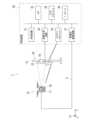
図3は、X線管保持装置10を備えるX線撮影システムの構成を示す概略図である。Figure 3 is a schematic diagram showing the configuration of an X-ray imaging system equipped with an X-ray
図3は、X線撮影システム1を示す。X線撮影システム1は、図1に示すX線管保持装置10と、立位撮影台20と、制御装置(例えば、コンソール)30とを備える。Figure 3 shows the
X線管保持装置10のX線管11(図1に図示)のU軸、つまり体軸AXは、後述する立位検出器23の横軸、つまり、X軸に平行である場合を示す。なお、X線管11のV軸は、立位検出器23の縦軸(鉛直方向)、つまり、Y軸に常に一致するものとする。The U-axis of the X-ray tube 11 (shown in FIG. 1) of the X-ray
X線管11は、飛行体13によりホバリングした状態で、高電圧電源回路37から電力供給を受けて、立位撮影台20の前に配置された患者の検査部位に対してX線を照射する。なお、X線管11の前段に、可動絞り部(図示省略)が設けられる。可動絞り部は、X線管11のX線照射口で、X線を遮蔽する物質から構成されたスライド可能な絞り羽根を有する。可動絞り部は、処理回路31による制御の下、可動絞り部によるX線照射口の開閉により、X線の拡がり角を変更することができる。なお、X線管11の前面に、X線管11によって発生されたX線の線質を調整する線質調整フィルタ(図示省略)が設けられてもよい。The
制御装置30による飛行体13の制御により、X線管保持装置10のX線管11は、所定の位置に移動することができる。例えば、飛行体13は、X線管11が、制御装置30によって設定された位置及び方位角に一致するように、自動操縦により移動される。By controlling the flying
立位撮影台20は、X線管11に対向する位置に配置される。立位撮影台20は、立位スタンド21と、移動機構22と、立位用のX線検出器(以下、「立位検出器」という)23とを備える。立位スタンド21は、移動機構22をとおして立位検出器23を保持する。移動機構22は、立位スタンド21に沿ってY軸方向にスライドすることで、立位検出器23を、立位スタンド21に沿ってY軸方向にスライドさせる。The standing
立位検出器23は、例えば、FPD(Flat Panel Detector)を含む。立位検出器23は、撮影用、透視用、又は、それらの兼用のX線検出器である。立位検出器23は、二次元に配列された複数の検出素子を備える。なお、立位検出器23の前面(即ち、X線入射面)に、グリッド(図示省略)が備えられてもよい。立位検出器23は、その前面にグリッドを備える。グリッドは、立位検出器23に入射する散乱線を吸収してX線画像のコントラストを改善するために、X線吸収の大きい鉛等によって形成されるグリッド板と透過しやすいアルミニウムや木材等とが交互に配置される。ここで、3次元系のX軸、Y軸、Z軸のうち、立位スタンド21の高さ方向をY軸方向とし、立位撮影台20の前に立つ患者の左右方向をX軸方向とし、X軸方向とY軸方向に直交する方向をZ軸方向とする。The standing
なお、立位検出器23は、FPDの他、A/D(Analog to digital)変換回路等を含む場合もある。A/D変換回路は、FPDから出力されるアナログ信号(ビデオ信号)を入力し、デジタルの画像信号に変換して制御装置30に出力する。In addition, the standing
制御装置30は、X線管保持装置10の飛行体13の飛行を制御することでX線管11の位置及び方位角を制御する機能と、X線管保持装置10の角度変更部122を制御することでX線管11の仰俯角を制御する機能と、X線撮影を制御する機能とを含む。制御装置30は、処理回路31と、メモリ32と、画像生成回路33と、入力インターフェース34と、ネットワークインターフェース35と、ディスプレイ36と、高電圧電源回路37とを備える。なお、画像生成回路33は、特定用途向け集積回路(ASIC:Application Specific Integrated Circuit)等によって構成されるものである。しかしながら、その場合に限定されるものではなく、画像生成回路33の機能の全部又は一部は、処理回路31がプログラムを実行することで実現されるものであってもよい。The
処理回路31は、制御装置30の全体の動作を制御する。処理回路31は、専用又は汎用のCPU(Central Processing Unit)、MPU(Micro Processor Unit)、又はGPU(Graphics Processing Unit)等のプロセッサの他、ASIC、及び、プログラマブル論理デバイス等を意味する。プログラマブル論理デバイスとしては、例えば、単純プログラマブル論理デバイス(SPLD:Simple Programmable Logic Device)、複合プログラマブル論理デバイス(CPLD:Complex Programmable Logic Device)、及び、フィールドプログラマブルゲートアレイ(FPGA:Field Programmable Gate Array)等が挙げられる。The
また、処理回路31は、単一の回路によって構成されてもよいし、複数の独立した処理回路要素の組み合わせによって構成されてもよい。後者の場合、メモリ32は処理回路要素ごとに個別に設けられてもよいし、単一のメモリ32が複数の処理回路要素の機能に対応するプログラムを記憶するものであってもよい。The
メモリ32は、例えば、RAM(Random Access Memory)、フラッシュメモリ(Flash Memory)等の半導体メモリ素子、ハードディスク、光ディスク等によって構成される。メモリ32は、USB(Universal Serial Bus)メモリ及びDVD(Digital Video Disk)等の可搬型メディアによって構成されてもよい。メモリ32は、処理回路31において用いられる各種処理プログラム(アプリケーションプログラムの他、OS(Operating System)等も含まれる)や、プログラムの実行に必要なデータを記憶する。また、OSに、操作者に対するディスプレイ36への情報の表示にグラフィックを多用し、基礎的な操作を入力インターフェース34によって行うことができるGUI(Graphic User Interface)を含めることもできる。なお、メモリ32は、記憶部の一例である。The
画像生成回路33は、処理回路31による制御の下、立位検出器23(又は、臥位検出器43)のA/D変換回路(図示省略)から出力された透過データに対して対数変換処理(LOG処理)を行って必要に応じて加算処理して、X線画像データを生成する。また、画像生成回路33は、処理回路31による制御の下、生成されたX線画像データに対して画像処理を施す。画像処理としては、データに対する拡大/階調/空間フィルタ処理や、時系列に蓄積されたデータの最小値/最大値トレース処理、及びノイズを除去するための加算処理等が挙げられる。Under the control of the
画像生成回路33は、生成したX線画像データをメモリ32等の記憶装置に記録する。なお、画像生成回路33は、画像生成部の一例である。The
入力インターフェース34は、操作者によって操作が可能な入力デバイスと、入力デバイスからの信号を入力する入力回路とを含む。入力デバイスは、マウス、キーボード、トラックボール、スイッチ、ボタン、ジョイスティック、操作面に触れることで入力操作を行うタッチパッド、表示画面とタッチパッドとが一化されたタッチスクリーン、光学センサを用いた非接触入力回路、音声入力回路等によって実現される。入力デバイスが操作者から入力操作を受け付けると、入力回路は当該入力操作に応じた電気信号を生成して処理回路31に出力する。なお、入力インターフェース34は、入力部の一例である。The
ネットワークインターフェース35は、ネットワークの形態に応じた種々の情報通信用プロトコルを実装する。ネットワークインターフェース35は、この各種プロトコルに従って、制御装置30と、外部の画像サーバ(図示省略)等の機器とを接続する。この接続には、電子ネットワークを介した電気的な接続等を適用することができる。ここで、電子ネットワークとは、電気通信技術を利用した情報通信網全般を意味し、無線/有線の病院基幹のLAN(Local Area Network)やインターネット網の他、電話通信回線網、光ファイバ通信ネットワーク、ケーブル通信ネットワーク及び衛星通信ネットワーク等を含む。なお、ネットワークインターフェース35は、ネットワーク接続部の一例である。The
ディスプレイ36は、各種の情報を表示する。例えば、ディスプレイ36は、画像生成回路33によって生成されたX線画像データや、後述する擬似画像データや、操作者からの各種操作を受け付けるためのGUI(Graphical User Interface)等を出力する。例えば、ディスプレイ36は、液晶ディスプレイやCRT(Cathode Ray Tube)ディスプレイ、OLED(Organic Light Emitting Diode)ディスプレイ等である。なお、ディスプレイ36は、表示部の一例である。The
高電圧電源回路37は、商用電源を入力として昇圧し、処理回路31による制御の下、ケーブルCを介してX線管保持装置10のX線管11に高電圧電力を供給する。The high-voltage
続いて、X線撮影システム1の制御装置30の機能について説明する。
図4は、制御装置30の機能の一例を示すブロック図である。 Next, the function of the
FIG. 4 is a block diagram showing an example of the functions of the
図4に示すように、処理回路31は、メモリ32に記憶された、又は、処理回路31内に直接組み込まれたコンピュータプログラムを読み出して実行することで、条件設定機能311と、位置制御機能312と、角度制御機能313と、X線撮影制御機能314とを実現する。以下、機能311~314がコンピュータプログラムの実行によりソフトウェア的に機能する場合を例に挙げて説明するが、機能311~314の全部又は一部の機能は、ASIC等の回路により実現されてもよい。また、機能311~313は、X線撮影制御機能314を有する制御装置30とは異なるコンピュータ、例えば、ダブレット型のコンピュータ等に備えられてもよい。As shown in FIG. 4, the
条件設定機能311は、入力インターフェース34を介した入力、又は、検査オーダに含まれる条件等により、SID(即ち、Z座標)等の撮影条件を設定する機能を含む。例えば、立位検出器23に正面からX線照射を行う場合、X線管11の3次元座標[X,Y,Z]のX軸座標は、立位検出器23の中心位置のX軸座標に一致し、X線管11の3次元座標[X,Y,Z]のY軸座標は、立位検出器23の中心位置のY軸座標に一致し、X線管11の3次元座標[X,Y,Z]のZ軸座標は、立位検出器23の中心位置のZ軸座標とSIDとの差に一致する。立位検出器23の位置は、予め取得されているものとする。なお、条件設定機能311は、条件設定部の一例である。The
位置制御機能312は、無線により、X線管保持装置10のX線管11の位置及び方位角を制御する機能を含む。位置制御機能312は、現在のX線管11の位置及び方位角と、条件設定機能311によって設定された目標のX線管11の位置及び方位角を測位し、X線管保持装置10の飛行ルートの設定を行う。例えば、立位検出器23に正面からX線照射を行う場合、位置制御機能312は、X線管11の体軸AXがX軸に平行になるように飛行体13の向きを制御することでX線管11の方位角を制御する。つまり、位置制御機能312は、X線管11が立位検出器23に正対するよう飛行体13を制御する。一方で、角度制御機能313は、飛行体13の向きを制御してX線管11の方位角を制御することで、立位検出器23に対して左側から、又は、右側からX線を照射することも可能である。なお、位置制御機能312は、位置制御部の一例である。The
角度制御機能313は、無線により、X線管保持装置10のX線管11の回転を制御する機能を含む。例えば、立位検出器23に正面からX線照射を行う場合、角度制御機能313は、X線管11のX線焦点と開口部Gとを結ぶ線がW軸に平行になるようにX線管11の仰俯角を制御する(図2(A)に図示)。つまり、角度制御機能313は、X線管11が立位検出器23に正対するよう角度変更部122を制御する。一方で、角度制御機能313は、X線管11の仰俯角を制御することで、立位検出器23に対して上方から、又は、下方からX線を照射することも可能である(図2(B),(C)に図示)。なお、角度制御機能313は、角度制御部の一例である。The
X線撮影制御機能314は、X線管保持装置10がホバリングしている状態で、無線により、X線管11と、立位検出器23等を制御して、また、ケーブルCを介して高電圧電源回路37からX線管11に電力供給することで、立位検出器23の前面に配置される患者の検査部位に対するX線撮影を制御する機能を含む。なお、X線撮影制御機能314は、X線撮影制御部の一例である。The X-ray
ここで、X線照射は、撮影と透視に大別される。撮影は、比較的高い管電流にてX線を照射する。一方で、透視は、比較的低い管電流にてX線を照射する。また、透視は、連続透視及びパルス透視に大別される。パルス透視とは、連続透視と異なり、X線のパルスが断続的に繰り返し照射される透視方法を意味する。パルス透視によれば、連続透視に比べ、透視画像の連続性(フレームレート)がやや劣るが患者に対する被曝線量を抑えることができる。Here, X-ray irradiation is broadly divided into radiography and fluoroscopy. Radiography irradiates X-rays with a relatively high tube current. On the other hand, fluoroscopy irradiates X-rays with a relatively low tube current. Fluoroscopy is also broadly divided into continuous fluoroscopy and pulsed fluoroscopy. Unlike continuous fluoroscopy, pulsed fluoroscopy refers to a fluoroscopy method in which X-ray pulses are intermittently and repeatedly irradiated. Compared to continuous fluoroscopy, pulsed fluoroscopy provides slightly inferior continuity (frame rate) of fluoroscopic images, but can reduce the radiation dose to the patient.
続いて、X線撮影システム1におけるX線撮影の制御方法について説明する。
図5は、X線撮影の制御方法をフローチャートとして示す図である。図5において、「ST」に数字を付した符号はフローチャートの各ステップを示す。 Next, a method for controlling X-ray photography in the
5 is a flowchart showing a method for controlling X-ray photography, in which "ST" followed by a number indicates each step of the flowchart.
条件設定機能311は、入力インターフェース34を介した入力、又は、検査オーダに含まれる条件等により、SID等の撮影条件を設定する(ステップST1)。位置制御機能312は、X線管保持装置10の飛行体13の飛行を制御することで、ステップST1によって設定されたSIDに基づく位置及び方位角となるようにX線管11の位置及び方位角をセットする(ステップST2)。ステップST2において、位置制御機能312は、現在のX線管11の位置及び方位角と、条件設定機能311によって設定された目標のX線管11の位置及び方位角を測位し、X線管保持装置10の飛行ルートの設定を行う。X線管保持装置10は、飛行ルートに沿って飛行を行い、X線管11の位置及び方位角をセットする。The
なお、ステップST2において、位置制御機能312は、所定の位置まで向かう最適な飛行ルートに機器等の障害物が存在する場合には、障害物を避けるように当該飛行ルートを変更し、障害物を避けるような飛行ルートを組んでもよい。障害物の位置は、予め設定されていてもよいし、画像センサ等の位置センサにより検出されるものであってもよい。これにより、X線管保持装置10が障害物に衝突する危険を回避できる。なお、位置制御機能312は、立位検出器23に対して正面となるようにX線管11の位置を制御し、正面からX線を照射させることが一般的であるが、立位検出器23に対して左側から、又は、右側からX線を照射させる場合がある。その場合、位置制御機能312は、X線管11の位置のX軸座標を制御するとともに、可動絞り部(図示省略)を制御してX線管11の方位角を制御する。In step ST2, if an obstacle such as equipment is present on the optimal flight route to the specified position, the
角度制御機能313は、ステップST2によりX線管保持装置10がホバリングしている状態で、X線管保持装置10のX線管11の回転を制御することで、X線管11の仰俯角をセットする(ステップST3)。なお、角度制御機能313は、立位検出器23に対して正面となるようにX線管11の位置を制御し、正面からX線を照射することが一般的であるが、立位検出器23に対して上方から、又は、下方からX線を照射させる場合がある。その場合、角度制御機能313は、X線管11の位置のY軸座標を制御するとともに、可動絞り部(図示省略)を制御してX線管11の仰俯角を制御する。While the X-ray
X線撮影制御機能314は、ステップST2によりX線管保持装置10がホバリングしている状態で、X線管11と、高電圧電源回路37と、立位検出器23等を制御することで、立位検出器23の前面に配置される患者の検査部位に対するX線撮影を実行する(ステップST4)。While the X-ray
画像生成回路33は、ステップST4のX線撮影により取得された透過データに基づいてX線画像データを生成する(ステップST5)。X線撮影制御機能314は、ステップST5によって生成されたX線画像データをメモリ32に保存するとともに、ディスプレイ36に表示させる(ステップST6)。The
以上のように、図1に示すX線管保持装置10によれば、X線管11を支持する天井レールやアームによりX線管11の可動範囲が制限されることがないので、X線管11の自由度の高い配置を実現することができる。また、X線管保持装置10をX線撮影システム1に適用すれば、大きなSIDによるX線撮影も実行可能である。As described above, with the X-ray
また、一般のX線撮影システムにX線管保持装置10を適用する一方で、院内の回診用のシステムにX線管保持装置10を適用することもできる。さらに、X線撮影システム1では、従来のX線撮影システムのようにX線管を支持するための天井工事を必要としないため、据え付け期間を短縮することもできる。In addition to being applied to a general X-ray imaging system, the X-ray
ここまで、図1に示すX線管保持装置10を、立位撮影に係るX線撮影システム1に適用する場合を例にとって説明したが、本発明は、その場合に限定されるものではない。例えば、本発明では、図1に示すX線管保持装置10を、臥位撮影に係るX線撮影システムに適用することもできる。その場合について説明する。Up to this point, the X-ray
図6は、X線管保持装置10を備えるX線撮影システムの構成を示す概略図である。Figure 6 is a schematic diagram showing the configuration of an X-ray imaging system equipped with an X-ray
図6は、X線撮影システム1Aを示す。X線撮影システム1Aは、図1に示すX線管保持装置10と、制御装置30と、臥位撮影台40とを備える。Figure 6 shows an
臥位撮影台40は、患者を載置可能なように横向きに配置され、X線管11からのX線を検出可能なように配置される。臥位撮影台40は、天板41と、寝台42と、臥位用のX線検出器(以下、「臥位検出器」という)43とを備える。The supine position imaging table 40 is positioned sideways so that a patient can be placed thereon, and is positioned so that X-rays from the
天板41は、臥位撮影台40の上部側に配置される板状の形状を有し、上部に患者を載置するものである。The
寝台42は、天板41を上方で支持する。寝台42は、制御装置30の処理回路31による制御の下、天板41を上下方向、左右方向、前後方向にスライドさせる。The
臥位検出器43は、立位検出器23(図3に図示)と同様に、例えば、FPDを含む。臥位検出器43は、撮影用、透視用、又は、それらの兼用のX線検出器である。臥位検出器43は、二次元に配列された複数の検出素子を備える。なお、臥位検出器43の前面(即ち、X線入射面)に、立位検出器23の前面と同様に、グリッド(図示省略)が備えられてもよい。The
臥位検出器43は、FPDの他、A/D変換回路等を含む場合もある。A/D変換回路は、FPDから出力されるアナログ信号(ビデオ信号)を入力し、デジタルの画像信号に変換して制御装置30に出力する。The
なお、図6に示すX線撮影システム1Aにおいて、図3に示すX線撮影システム1と同一部材には同一符号を付して説明を省略する。また、X線撮影システム1Aの機能は、図4に示すX線撮影システム1の機能と同等であるので、説明を省略する。さらに、X線撮影システム1AによるX線撮影の制御方法は、図5に示すX線撮影システム1によるX線撮影の制御方法と同等であるので、説明を省略する。In the
以上のように、図1に示すX線管保持装置10をX線撮影システム1Aに適用すれば、大きなSIDによるX線撮影も実行可能である。As described above, if the X-ray
(第1の変形例)
図6に示すX線撮影システム1Aによれば、トモシンセシス撮影を行うことも可能である。その場合について、図7を用いて説明する。 (First Modification)
According to the
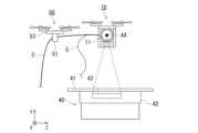
図7は、X線撮影システム1Aにおいて、トモシンセシス撮影を説明するための図である。Figure 7 is a diagram for explaining tomosynthesis imaging in the
図7は、X線管保持装置10と、臥位撮影台40とを示す。図7に示すように、X線管保持装置10、つまり、X線管11がZ軸方向に直線的にスライド移動されるとともにX線管11の仰俯角を制御することで、トモシンセシス撮影が行われる。また、X線管11は、Z軸方向に直線的にスライド移動される場合に限定されるものでもなく、X線管11の焦点位置と臥位検出器43の中心との中点を中心にした円弧方向に移動することでトモシンセシス撮影を実現するものであってもよい。さらに、臥位検出器43は、固定されたものに限定されるものではなく、X線管11のZ軸正方向の移動に合わせて、Z軸負方向に移動されることでトモシンセシス撮影が行われてもよい。Figure 7 shows the X-ray
このように、X線管保持装置10を適用したX線撮影システム1Aによれば、トモシンセシス撮影のようなX線管が一定の直線又は円弧のような軌道を行う場合、検査室内のカーテンレールのような障害により撮影できない事情もない。X線撮影システム1Aによれば、カーテンレールを避けて、かつ、もともと予定していたトモシンセシスの軌道に近い撮影を行うことができる。つまり、X線撮影システム1Aによれば、従来諦めていたX線管の軌道で撮影を行えるようになり、検査の幅を広げることができる。In this way, with the
(第2の変形例)
X線撮影システム1,1Aに、1個のX線管保持装置10のみならず、複数のX線管保持装置10を適用してもよい。複数のX線管保持装置10を順次交換して使用することにより、ヒートユニット(HU)の小さいX線管11でも連続して撮影を続けることができる。X線管11を、飛行体13を使って飛ばすことを考えると、X線管11を小さく軽量化することが好適である。そのためには、X線管11として、陽極を回転させる回転陽極を搭載したものを採用することが困難で、固定陽極のものを搭載することが望ましい。その場合、同じX線条件であっても固定陽極のX線管の場合、早く熱くなってしまい撮影を行えない事態になりかねない。 (Second Modification)
The
そこで、バックアップ用として1個以上のX線管保持装置10を使用できるようにする。制御装置30は、複数のX線管保持装置10のうちアクティブなX線管保持装置10を制御してX線画像データを取得する。そうすることで、1つ目のX線管保持装置10のX線管11で撮影できなくなったとしても、他のX線管保持装置10を使って撮影を継続して行える。なお、X線撮影制御機能314は、2個のX線管保持装置10を制御することで、2個のX線管保持装置10にそれぞれ対応する2個のX線管11から交互にX線照射を行わせて立体視用のX線画像データ取得することもできる。Therefore, one or more X-ray
(第3の変形例)
X線撮影システム1,1Aに、高電圧電源回路37からX線管11への電力供給のためのケーブルが弛まないように支持するケーブル支持装置50をさらに設けてもよい。 (Third Modification)
The
図8は、X線撮影システム1,1Aにおいて、ケーブル支持装置50によるケーブルの支持を説明するための図である。Figure 8 is a diagram for explaining how the cable is supported by the
図8は、X線管保持装置10と、臥位撮影台40と、ケーブル支持装置50とを示す。ケーブル支持装置50は、X線管保持装置10の飛行体13(図1に図示)と同等の構成を備える飛行体53と、飛行体53の下部に、高電圧電源回路37からX線管11への電力供給のためのケーブルCを支持する支持部51(例えば、滑車)とを備える。ケーブル支持装置50は、X線管保持装置10の移動に追従して移動することが望ましい。Figure 8 shows the X-ray
X線管保持装置10が自由に飛行できるので、ケーブルCが臥位撮影台40上の患者に垂れ下がってしまうことが想定される(図8の太い破線)。そこで、飛行体53により飛行するケーブル支持装置50にケーブルCを支持させた上で、位置制御機能312は、無線によりX線管保持装置10の位置及び方位角を制御するとともに、X線管保持装置10の位置に追従するように無線によりケーブル支持装置50の位置を制御する。それにより、ケーブルCが臥位撮影台40上の患者に垂れ下がってしまうことを回避することができる。なお、ケーブル支持装置50を用いずに、X線管保持装置10の飛行体13に、ケーブルCを支持するためのアームをさらに備えてもよい。この場合でも、ケーブル支持装置50による効果と同等の効果を簡易に得ることができる。Because the X-ray
(第4の変形例)
X線撮影システム1,1Aにおいて、X線撮影制御機能314は、飛行体13の飛行状態に応じてX線管11からのX線の照射を制御してもよい。飛行体13、つまり、X線管11の静止状態、又は、安定した飛行の状態の時に撮影しなければ、取得されるX線画像にブレが発生しかねない。そのため、X線撮影制御機能314は、X線管11の静止状態、又は、安定した飛行の状態の時に撮影を行うように制御する。例えば、X線撮影制御機能314は、飛行体13の位置情報の、時間当たりの移動量を計測することで、X線管11の静止状態及び安定状態を認識することができる。これにより、X線管11の動きによるX線画像のブレを防止することができる。 (Fourth Modification)
In the
(第5の変形例)
飛行体13に搭載される可動絞り部(図示省略)は、飛行体13の最大積載重量との関係で、軽量であることが好適である。そのため、飛行体13に搭載される可動絞り部は、機能が制限されたものとなることが想定される。例えば、重量の観点から飛行体13に上下左右に非対称に動作するような複雑な絞りを搭載できない。そこで、X線撮影システム1Aに、追加的な可動絞り部が搭載された、X線管保持装置10の着地装置44を設けてもよい。 (Fifth Modification)
The movable aperture unit (not shown) mounted on the flying
図9(A)は、X線管保持装置10の着地装置44の構成例を示す図である。図9(B)は、着地装置44の配置例を示す図である。Figure 9 (A) is a diagram showing an example of the configuration of the
図9(A)に示すように、着地装置44は、X線管保持装置10の着地溝44a,44bと、可動絞り部44cを備える。図9(B)に示すように、着地装置44の着地溝44a,44bに、寝台42(又は、天板41)に固定されたX線管保持装置10の脚部が接地することで、X線管保持装置10が臥位撮影台40に位置合わせされ、固定される。As shown in FIG. 9(A), the
テレビ寝台装置を用いた泌尿器の検査等のように、X線垂の下側だけを使用したい検査においては、非対称に動作する絞り羽を備えた可動絞り部を使用して検査を行いたい場合がある。そこで、臥位撮影台40に所望の可動絞り部44cを有する着地装置44を設置した上で、位置制御機能312は、X線管保持装置10が着地装置44の所定位置に着地するように制御することで、所望の可動絞り部44cを使用した撮影が可能である。In examinations where only the lower side of the X-ray tube is to be used, such as urological examinations using a TV bed device, it may be desirable to perform the examination using a movable aperture section with aperture blades that move asymmetrically. Therefore, after placing a
(第6の変形例)
図1に示すX線管保持装置10は、高電圧電源回路を備えていない。一方で、制御装置30が高電圧電源回路37を備え、X線管保持装置10のX線管11は、制御装置30の高電圧電源回路37から電力を供給する。しかしながら、そのような構成に限定されるものではない。X線管11を保持するX線管保持装置が、高電圧電源回路を備えてもよい。 (Sixth Modification)
1 does not include a high-voltage power supply circuit. On the other hand, the
図10は、変形例に係るX線管保持装置の構成を示す概略図である。Figure 10 is a schematic diagram showing the configuration of an X-ray tube holding device according to a modified example.
図10は、変形例に係るX線管保持装置10Bを示す。X線管保持装置10Bは、X線管11と、保持機構12と、飛行体13と、高電圧電源回路16と、蓄電池(バッテリ)17とを備える。Figure 10 shows an X-ray
高電圧電源回路16は、バッテリ17の電源を入力として昇圧し、処理回路31による制御の下、X線管保持装置10BのX線管11に高電圧電力を供給する。The high-voltage
なお、図10に示すX線管保持装置10Bにおいて、図1に示すX線管保持装置10と同一部材には同一符号を付して説明を省略する。In addition, in the X-ray
図11は、X線管保持装置10Bを備えるX線撮影システムの構成を示す概略図である。Figure 11 is a schematic diagram showing the configuration of an X-ray imaging system equipped with an X-ray
図11は、X線撮影システム1Bを示す。X線撮影システム1Bは、図10に示すX線管保持装置10Bと、立位撮影台20と、制御装置30Bとを備える。Figure 11 shows an
X線管保持装置10BのX線管11(図1に図示)のU軸、つまり体軸AXは、後述する立位検出器23の横軸、つまり、X軸に平行である場合を示す。なお、X線管11のV軸は、立位検出器23の縦軸(鉛直方向)、つまり、Y軸に常に一致するものとする。The U-axis of the X-ray tube 11 (shown in FIG. 1) of the X-ray
X線管11は、高電圧電源回路16から電力供給を受けて、立位撮影台20の前に配置された患者にX線を照射する。なお、X線管11の前段に、可動絞り部(図示省略)が設けられる。可動絞り部は、X線管11のX線照射口で、X線を遮蔽する物質から構成された、スライド可能な絞り羽根を有する。可動絞り部は、処理回路31による制御の下、可動絞り部によるX線照射口の開閉により、X線の拡がり角を変更することができる。なお、X線管11の前面に、X線管11によって発生されたX線の線質を調整する線質調整フィルタ(図示省略)が設けられてもよい。The
制御装置30Bの位置制御機能312による飛行体13の制御により、X線管保持装置10BのX線管11は、所定の位置に移動することができる。例えば、X線管11は、所定の3次元座標[X,Y,Z]に移動することができる。The
制御装置30Bは、X線管保持装置10Bの飛行体13の飛行を制御することでX線管11の位置及び方位角を制御する機能と、X線管保持装置10Bの角度変更部122を制御することでX線管11の仰俯角を制御する機能と、X線撮影を制御する機能とを含む。制御装置30Bは、処理回路31と、メモリ32と、画像生成回路33と、入力インターフェース34と、ネットワークインターフェース35と、ディスプレイ36とを備える。つまり、制御装置30Bは、制御装置30(図3に図示)とは異なり、高電圧電源回路37を備えていない。The
なお、図11に示すX線撮影システム1Bにおいて、図3に示すX線撮影システム1と同一部材には同一符号を付して説明を省略する。また、X線撮影システム1Bの機能は、X線撮影制御機能314の機能以外、図4に示すX線撮影システム1の機能と同等であるので、説明を省略する。X線撮影システム1BにおけるX線撮影制御機能314は、X線管保持装置10Bがホバリングしている状態で、無線により、X線管11と、立位検出器23等を制御して、また、無線により、高電圧電源回路16からX線管11への電力供給を制御することで、立位検出器23の前面(又は、臥位検出器43上)に配置される患者の検査部位に対するX線撮影を制御する機能を含む。さらに、X線撮影システム1BによるX線撮影の制御方法は、図5に示すX線撮影システム1によるX線撮影の制御方法と同等であるので、説明を省略する。In the
以上のように、図11に示すX線管保持装置10Bによれば、X線管保持装置10(図1に図示)と同様に、X線管11を支持する天井レールやアームによりX線管11の可動範囲が制限されることがないので、X線管の自由度の高い配置を実現することができる。また、X線管保持装置10BをX線撮影システム1Bに適用すれば、大きなSIDによるX線撮影も実行可能である。さらに、図11に示すX線管保持装置10Bによれば、高電圧電源回路16と商用電源とをつなぐケーブルが不要となることによりX線管11の可動範囲が制限されることがないので、X線管保持装置10(図1に図示)の場合よりさらに、X線管11の自由度の高い配置を実現することができる。As described above, according to the X-ray
なお、条件設定機能311は、条件設定部の一例である。位置制御機能312は、位置制御部の一例である。角度制御機能313は、角度制御部の一例である。X線撮影制御機能314は、X線撮影制御部の一例である。The
以上説明した少なくとも1つの実施形態によれば、X線管の自由度の高い配置を実現することができる。At least one of the embodiments described above allows for highly flexible placement of the X-ray tube.
いくつかの実施形態を説明したが、これらの実施形態は、例として提示したものであり、発明の範囲を限定することは意図していない。これら新規な実施形態は、その他の様々な形態で実施されることが可能であり、発明の要旨を逸脱しない範囲で、種々の省略、置き換え、変更、実施形態同士の組み合わせを行うことができる。これら実施形態やその変形は、発明の範囲や要旨に含まれるとともに、特許請求の範囲に記載された発明とその均等の範囲に含まれる。Although several embodiments have been described, these embodiments are presented as examples and are not intended to limit the scope of the invention. These novel embodiments can be implemented in various other forms, and various omissions, substitutions, modifications, and combinations of embodiments can be made without departing from the gist of the invention. These embodiments and their modifications are included within the scope and gist of the invention, and are included in the scope of the invention and its equivalents as set forth in the claims.
1,1A,1B X線撮影システム
10,10B X線管保持装置
11 X線管
12 保持機構
13 飛行体
14,15 位置センサ
16,37 高電圧電源回路
17 バッテリ
20 立位撮影台
23 立位検出器
30 制御装置
31 処理回路
311 条件設定機能
312 位置制御機能
313 角度制御機能
314 X線撮影制御機能
40 臥位撮影台
43 臥位検出器
50 ケーブル支持装置
51 支持部
53 飛行体
Claims (10)
Translated fromJapanese前記複数のX線管保持装置を制御する制御装置と、
を備え、
前記制御装置は、前記複数のX線管保持装置のうちアクティブなX線管保持装置を制御してX線画像データを取得するか、又は、2個のX線管保持装置を制御することで、前記2個のX線管保持装置にそれぞれ対応する2個のX線管から交互にX線照射を行わせて立体視用のX線画像データを取得する、
X線撮影システム。a plurality of X-ray tube holding devices each including an X-ray tube, a holding mechanism for holding the X-ray tube, and an aircraft carrying the holding mechanism;
a control device for controlling the plurality of X-ray tube holding devices;
Equippedwith
the control device controls an active X-ray tube holding device among the plurality of X-ray tube holding devices to acquire X-ray image data, or controls two X-ray tube holding devices to alternately irradiate X-rays from two X-ray tubes corresponding to the two X-ray tube holding devices, therebyacquiring X-ray image data for stereoscopic viewing.
X- ray imaging system.
前記X線管保持装置を制御する制御装置と、
X線検出器を備える臥位撮影台と、
前記臥位撮影台に取り付けられる着地装置と、
を備え、
前記着地装置は、前記X線管保持装置が着地可能であり、可動絞り部を搭載する、
X線撮影システム。an X-ray tube holding device including an X-ray tube, a holding mechanism for holding the X-ray tube, and an aircraft carrying the holding mechanism;
A control device for controlling the X-ray tube holding device;
a supine imaging table equipped with an X-ray detector;
A landing device attached to the supine position imaging platform;
Equippedwith
the landing device is capable of landing on the X-ray tube holding device and is equipped with a movable diaphragm unit;
X- ray imaging system.
前記制御装置は、前記高電圧電源回路及び前記蓄電池を制御してX線撮影を制御する、
請求項1又は2に記載のX線撮影システム。 The X-ray tube holding device further includes a high voltage power supply circuit and a storage battery.
the control device controls the high-voltage power supply circuit and the storage battery to control X-ray photography;
3. The X-ray imaging system according to claim1 .
を備える請求項1又は2に記載のX線撮影システム。 the flying vehicle includes an arm supporting a cable for supplying power from a high voltage power supply circuit to the X-ray tube;
3. The X-ray imaging system according to claim1, further comprising:
前記X線管保持装置を制御する制御装置と、
ケーブル支持装置と、
を備え、
前記ケーブル支持装置は、
第2の飛行体と、
前記第2の飛行体の下部に、高電圧電源回路から前記X線管への電力供給のためのケーブルを支持する支持部と、
を備えるX線撮影システム。an X-ray tube holding device including an X-ray tube, a holding mechanism for holding the X-ray tube, and an aircraft carrying the holding mechanism;
A control device for controlling the X-ray tube holding device;
A cable support device;
Equippedwith
The cable support device includes:
A second air vehicle; and
a support section provided at a lower portion of the second flying object for supporting a cable for supplying power from a high voltage power supply circuit to the X-ray tube;
AnX- ray imaging system comprising:
請求項1乃至5のいずれか1項に記載のX線撮影システム。 An angle change unit that changes the elevation/depression angle of the X-ray tube is further provided.
6.The X-ray imaging systemaccording to claim 1 .
前記制御装置は、前記X線管が前記X線検出器に正対するよう前記角度変更部を制御する、
請求項6に記載のX線撮影システム。 Further comprising an X-ray detector;
the control device controls the angle changing unit so that the X-ray tube faces the X-ray detector directly.
7. The X-ray imaging system according to claim6 .
請求項7に記載のX線撮影システム。 The control device acquires position information of the X-ray detector and controls the flying object based on the position information.
8. The X-ray imaging system according to claim7 .
請求項1乃至8のいずれか1項に記載のX線撮影システム。 when an obstacle is present on a flight route of the X-ray tube holding device, the control device changes the flight route so as to avoid the obstacle.
9. The X-ray imaging system according to claim1 .
請求項1乃至9のいずれか1項に記載のX線撮影システム。 the control device controls the emission of X-rays from the X-ray tube in accordance with a flight state of the X-ray tube holding device.
10. The X-ray imaging system according to claim1 .
Priority Applications (3)
| Application Number | Priority Date | Filing Date | Title |
|---|---|---|---|
| JP2020147029AJP7514704B2 (en) | 2020-09-01 | 2020-09-01 | X-ray tube holding device and X-ray imaging system |
| US17/412,681US12036056B2 (en) | 2020-09-01 | 2021-08-26 | X-ray tube holding apparatus and X-ray imaging system |
| CN202110992408.1ACN114098774B (en) | 2020-09-01 | 2021-08-27 | X-ray tube holding device and X-ray imaging system |
Applications Claiming Priority (1)
| Application Number | Priority Date | Filing Date | Title |
|---|---|---|---|
| JP2020147029AJP7514704B2 (en) | 2020-09-01 | 2020-09-01 | X-ray tube holding device and X-ray imaging system |
Publications (3)
| Publication Number | Publication Date |
|---|---|
| JP2022041680A JP2022041680A (en) | 2022-03-11 |
| JP2022041680A5 JP2022041680A5 (en) | 2023-06-28 |
| JP7514704B2true JP7514704B2 (en) | 2024-07-11 |
Family
ID=80355952
Family Applications (1)
| Application Number | Title | Priority Date | Filing Date |
|---|---|---|---|
| JP2020147029AActiveJP7514704B2 (en) | 2020-09-01 | 2020-09-01 | X-ray tube holding device and X-ray imaging system |
Country Status (3)
| Country | Link |
|---|---|
| US (1) | US12036056B2 (en) |
| JP (1) | JP7514704B2 (en) |
| CN (1) | CN114098774B (en) |
Families Citing this family (4)
| Publication number | Priority date | Publication date | Assignee | Title |
|---|---|---|---|---|
| US12092432B2 (en)* | 2020-10-02 | 2024-09-17 | United States Of America, As Represented By The Secretary Of The Navy | Glide trajectory optimization for aerospace vehicles |
| CN114088743B (en)* | 2021-11-18 | 2023-06-06 | 国网湖南省电力有限公司 | A multi-split wire splicing tube live flaw detection system and its application method |
| US20250263182A1 (en)* | 2024-02-18 | 2025-08-21 | Sokil, Inc. | UAV System And A Method For Survey And Detection Of Magnetized Unexploded Ordnance |
| CN119310115B (en)* | 2024-12-13 | 2025-04-04 | 陕西风雷移航空科技有限公司 | Device and method for carrying out electric power flaw detection by matching unmanned aerial vehicle with slide rail robot |
Citations (4)
| Publication number | Priority date | Publication date | Assignee | Title |
|---|---|---|---|---|
| US20170329037A1 (en) | 2016-02-01 | 2017-11-16 | The University Of North Carolina At Chapel Hill | Mobile and free-form x-ray imaging systems and methods |
| WO2018207678A1 (en) | 2017-05-11 | 2018-11-15 | 株式会社堀場製作所 | Unmanned aerial vehicle |
| WO2019063434A1 (en) | 2017-09-26 | 2019-04-04 | Koninklijke Philips N.V. | Mobile x-ray imaging system |
| WO2019187166A1 (en) | 2018-03-31 | 2019-10-03 | つくばテクノロジー株式会社 | X-ray inspection device for drone, x-ray inspection device employing drone, and x-ray generating device for drone |
Family Cites Families (13)
| Publication number | Priority date | Publication date | Assignee | Title |
|---|---|---|---|---|
| JPH05316525A (en)* | 1992-05-13 | 1993-11-26 | Matsushita Electric Ind Co Ltd | Landing correction device |
| RU2113000C1 (en)* | 1997-07-21 | 1998-06-10 | Товарищество с ограниченной ответственностью "МТ" | Method for prospecting of mineral deposits using their radiation, device which implements said method, microleptonic indicator |
| US20130233964A1 (en)* | 2012-03-07 | 2013-09-12 | Aurora Flight Sciences Corporation | Tethered aerial system for data gathering |
| EP3374263A4 (en)* | 2015-11-10 | 2019-05-08 | Matternet, Inc. | METHODS AND TRANSPORT SYSTEMS USING PILOT-FREE AIR VEHICLES |
| CN109414588A (en) | 2016-04-14 | 2019-03-01 | 费尔德雷克卡罗鲁伊斯有限公司 | A kind of radiotherapy equipment comprising ion module and ultraviolet light source |
| GB2549331A (en)* | 2016-04-15 | 2017-10-18 | Univ Antwerpen | Mobile imaging of an object using penetrating radiation |
| CN111712434A (en)* | 2018-02-14 | 2020-09-25 | 福特全球技术公司 | self-centering landing platform |
| US10850841B2 (en)* | 2018-06-20 | 2020-12-01 | Intel Corporation | Unmanned aerial vehicle and method for operating an unmanned aerial vehicle |
| CN109061707A (en)* | 2018-07-23 | 2018-12-21 | 河南省核工业放射性核素检测中心 | Nuclear pollution region nuclear radiation monitoring system and method based on unmanned plane |
| US10881372B2 (en)* | 2018-12-12 | 2021-01-05 | Shimadzu Corporation | X-ray imaging apparatus |
| EP3756550A1 (en)* | 2019-06-28 | 2020-12-30 | Koninklijke Philips N.V. | Shielding device for use in medical imaging |
| CN110470275A (en)* | 2019-09-02 | 2019-11-19 | 长沙理工大学 | A method of withered riverbed bed ripples morphological parameters are measured based on UAV aerial survey terrain data |
| GB201915412D0 (en)* | 2019-10-24 | 2019-12-11 | Johnson Matthey Plc | Scanning system and method for scanning vessels |
- 2020
- 2020-09-01JPJP2020147029Apatent/JP7514704B2/enactiveActive
- 2021
- 2021-08-26USUS17/412,681patent/US12036056B2/enactiveActive
- 2021-08-27CNCN202110992408.1Apatent/CN114098774B/enactiveActive
Patent Citations (4)
| Publication number | Priority date | Publication date | Assignee | Title |
|---|---|---|---|---|
| US20170329037A1 (en) | 2016-02-01 | 2017-11-16 | The University Of North Carolina At Chapel Hill | Mobile and free-form x-ray imaging systems and methods |
| WO2018207678A1 (en) | 2017-05-11 | 2018-11-15 | 株式会社堀場製作所 | Unmanned aerial vehicle |
| WO2019063434A1 (en) | 2017-09-26 | 2019-04-04 | Koninklijke Philips N.V. | Mobile x-ray imaging system |
| WO2019187166A1 (en) | 2018-03-31 | 2019-10-03 | つくばテクノロジー株式会社 | X-ray inspection device for drone, x-ray inspection device employing drone, and x-ray generating device for drone |
Also Published As
| Publication number | Publication date |
|---|---|
| US12036056B2 (en) | 2024-07-16 |
| CN114098774B (en) | 2024-10-22 |
| US20220061788A1 (en) | 2022-03-03 |
| JP2022041680A (en) | 2022-03-11 |
| CN114098774A (en) | 2022-03-01 |
Similar Documents
| Publication | Publication Date | Title |
|---|---|---|
| JP7514704B2 (en) | X-ray tube holding device and X-ray imaging system | |
| US9795347B2 (en) | Scanning system for three-dimensional imaging | |
| KR20040054791A (en) | 3d reconstruction system and method utilizing a variable x-ray source to image distance | |
| US10531850B2 (en) | Mobile X-ray imaging with detector docking within a spatially registered compartment | |
| JP2005296647A (en) | Stationary tomographic mammography system | |
| JP2014147689A (en) | Medical image diagnostic apparatus, nuclear medicine diagnostic system, x-ray ct apparatus and bed device | |
| US7632014B2 (en) | Large X-ray detector variable centering for angulation enhancement | |
| JP7436443B2 (en) | X-ray diagnostic equipment | |
| JP7325943B2 (en) | MEDICAL IMAGE DIAGNOSTIC SYSTEM AND PARAMETER SELECTION METHOD | |
| US20060291614A1 (en) | Radiographic apparatus | |
| JP7532616B2 (en) | X-ray CT scanner | |
| JP7224829B2 (en) | Medical image processing apparatus and method | |
| JP7140566B2 (en) | X-ray CT device and imaging planning device | |
| JP2022026261A (en) | X-ray CT device | |
| JP5997941B2 (en) | X-ray diagnostic equipment | |
| JP2021171505A (en) | X-ray diagnostic device and detector accommodating device | |
| JP7395385B2 (en) | Angio CT device | |
| JP7451265B2 (en) | Treatment support devices, treatment support programs, and treatment planning devices | |
| JP7118744B2 (en) | X-ray CT apparatus and imaging condition calculation method | |
| JP2022178052A (en) | X-RAY CT APPARATUS AND CONTROL METHOD OF X-RAY CT APPARATUS | |
| JP2006288910A (en) | Tomographic apparatus | |
| JP2022523432A (en) | X-ray imager | |
| JP2021023662A (en) | X-ray ct apparatus | |
| JP2018117705A (en) | X-ray computer tomographic apparatus | |
| JP2019122537A (en) | X-ray imaging apparatus, installation support apparatus, and jig for installation |
Legal Events
| Date | Code | Title | Description |
|---|---|---|---|
| A521 | Request for written amendment filed | Free format text:JAPANESE INTERMEDIATE CODE: A523 Effective date:20230620 | |
| A621 | Written request for application examination | Free format text:JAPANESE INTERMEDIATE CODE: A621 Effective date:20230620 | |
| A977 | Report on retrieval | Free format text:JAPANESE INTERMEDIATE CODE: A971007 Effective date:20231220 | |
| A131 | Notification of reasons for refusal | Free format text:JAPANESE INTERMEDIATE CODE: A131 Effective date:20240123 | |
| A521 | Request for written amendment filed | Free format text:JAPANESE INTERMEDIATE CODE: A523 Effective date:20240308 | |
| TRDD | Decision of grant or rejection written | ||
| A01 | Written decision to grant a patent or to grant a registration (utility model) | Free format text:JAPANESE INTERMEDIATE CODE: A01 Effective date:20240604 | |
| A61 | First payment of annual fees (during grant procedure) | Free format text:JAPANESE INTERMEDIATE CODE: A61 Effective date:20240701 | |
| R150 | Certificate of patent or registration of utility model | Ref document number:7514704 Country of ref document:JP Free format text:JAPANESE INTERMEDIATE CODE: R150 |