JP7514303B2 - Remote automated chemical switching system for use with automated sampling equipment. - Google Patents
Remote automated chemical switching system for use with automated sampling equipment.Download PDFInfo
- Publication number
- JP7514303B2 JP7514303B2JP2022520199AJP2022520199AJP7514303B2JP 7514303 B2JP7514303 B2JP 7514303B2JP 2022520199 AJP2022520199 AJP 2022520199AJP 2022520199 AJP2022520199 AJP 2022520199AJP 7514303 B2JP7514303 B2JP 7514303B2
- Authority
- JP
- Japan
- Prior art keywords
- sample
- analyzers
- controller
- contaminant
- remote sampling
- Prior art date
- Legal status (The legal status is an assumption and is not a legal conclusion. Google has not performed a legal analysis and makes no representation as to the accuracy of the status listed.)
- Active
Links
Images


Classifications
- G—PHYSICS
- G01—MEASURING; TESTING
- G01N—INVESTIGATING OR ANALYSING MATERIALS BY DETERMINING THEIR CHEMICAL OR PHYSICAL PROPERTIES
- G01N35/00—Automatic analysis not limited to methods or materials provided for in any single one of groups G01N1/00 - G01N33/00; Handling materials therefor
- G01N35/02—Automatic analysis not limited to methods or materials provided for in any single one of groups G01N1/00 - G01N33/00; Handling materials therefor using a plurality of sample containers moved by a conveyor system past one or more treatment or analysis stations
- G01N35/04—Details of the conveyor system
- G—PHYSICS
- G01—MEASURING; TESTING
- G01N—INVESTIGATING OR ANALYSING MATERIALS BY DETERMINING THEIR CHEMICAL OR PHYSICAL PROPERTIES
- G01N35/00—Automatic analysis not limited to methods or materials provided for in any single one of groups G01N1/00 - G01N33/00; Handling materials therefor
- G01N35/00584—Control arrangements for automatic analysers
- G01N35/00594—Quality control, including calibration or testing of components of the analyser
- G01N35/00613—Quality control
- G—PHYSICS
- G01—MEASURING; TESTING
- G01N—INVESTIGATING OR ANALYSING MATERIALS BY DETERMINING THEIR CHEMICAL OR PHYSICAL PROPERTIES
- G01N35/00—Automatic analysis not limited to methods or materials provided for in any single one of groups G01N1/00 - G01N33/00; Handling materials therefor
- G01N35/00584—Control arrangements for automatic analysers
- G01N35/00722—Communications; Identification
- G01N35/00871—Communications between instruments or with remote terminals
- G—PHYSICS
- G01—MEASURING; TESTING
- G01N—INVESTIGATING OR ANALYSING MATERIALS BY DETERMINING THEIR CHEMICAL OR PHYSICAL PROPERTIES
- G01N35/00—Automatic analysis not limited to methods or materials provided for in any single one of groups G01N1/00 - G01N33/00; Handling materials therefor
- G01N35/10—Devices for transferring samples or any liquids to, in, or from, the analysis apparatus, e.g. suction devices, injection devices
- G01N35/1065—Multiple transfer devices
- G—PHYSICS
- G01—MEASURING; TESTING
- G01N—INVESTIGATING OR ANALYSING MATERIALS BY DETERMINING THEIR CHEMICAL OR PHYSICAL PROPERTIES
- G01N35/00—Automatic analysis not limited to methods or materials provided for in any single one of groups G01N1/00 - G01N33/00; Handling materials therefor
- G01N35/00584—Control arrangements for automatic analysers
- G01N35/00722—Communications; Identification
- G01N2035/00891—Displaying information to the operator
- G01N2035/009—Displaying information to the operator alarms, e.g. audible
Landscapes
- Analytical Chemistry (AREA)
- Immunology (AREA)
- Physics & Mathematics (AREA)
- Health & Medical Sciences (AREA)
- Life Sciences & Earth Sciences (AREA)
- Chemical & Material Sciences (AREA)
- General Health & Medical Sciences (AREA)
- Biochemistry (AREA)
- Pathology (AREA)
- General Physics & Mathematics (AREA)
- Engineering & Computer Science (AREA)
- Quality & Reliability (AREA)
- Sampling And Sample Adjustment (AREA)
- Automatic Analysis And Handling Materials Therefor (AREA)
Description
Translated fromJapanese多くの実験環境では、多数の化学的試料又は生物学的試料を一度に分析することがよく必要とされる。このような処理を合理化するために、試料の操作は機械化されてきている。このような機械化されたサンプリングは、オートサンプリングと呼ばれることができ、自動サンプリング装置又はオートサンプラを使用して行われ得る。In many laboratory environments, it is often necessary to analyze many chemical or biological samples at once. To streamline such processes, sample manipulation has become mechanized. Such mechanized sampling can be called autosampling and can be performed using an automatic sampling device or autosampler.
誘導結合プラズマ(ICP: Inductively Coupled Plasma)分光分析は、液体試料中の微量元素濃度及び同位体比を測定するために一般的に使用される分析技術である。ICP分光分析には、電磁的に生成されて部分的に電離したアルゴンプラズマが使用される。当該アルゴンプラズマは、約7000Kの温度に達する。試料がプラズマに導入されると、高温によって試料原子の電離又は発光が引き起こされる。各化学元素は特有の質量又は発光スペクトルを生じるため、発光の質量又は光のスペクトルを測定することによって、元の試料の元素組成を決定することが可能になる。Inductively Coupled Plasma (ICP) spectroscopy is a commonly used analytical technique for measuring trace element concentrations and isotope ratios in liquid samples. ICP spectroscopy uses an electromagnetically generated, partially ionized argon plasma that reaches a temperature of approximately 7000 K. When a sample is introduced into the plasma, the high temperature causes the sample atoms to ionize or emit light. Each chemical element produces a unique mass or emission spectrum, so by measuring the mass or light spectrum of the emission, it is possible to determine the elemental composition of the original sample.
液体試料を分析のためにICP分光分析装置(例えば、誘導結合プラズマ質量分析装置(ICP/ICP-MS: Inductively Coupled Plasma Mass Spectrometer)、誘導結合プラズマ原子発光分析装置(ICP-AES: Inductively Coupled Plasma Atomic Emission Spectrometer)など)又は他の試料検出器若しくは分析装置に導入するために、試料導入システムが使用されてもよい。例えば、試料導入システムは、容器から液体試料のアリコートを取り出し、その後にアリコートをネブライザに移送してもよい。ネブライザは、アリコートを、ICP分光分析装置によってプラズマ中で電離させるために適した多分散エアロゾルに変える。その後、エアロゾルは、大きなエアロゾル粒子の除去のために、スプレーチャンバで選別される。エアロゾルは、スプレーチャンバを離れると、分析のためのICP-MS又はICP-AES装置のプラズマトーチアセンブリによってプラズマに導入される。A sample introduction system may be used to introduce the liquid sample into an ICP spectrometer (e.g., an Inductively Coupled Plasma Mass Spectrometer (ICP/ICP-MS), an Inductively Coupled Plasma Atomic Emission Spectrometer (ICP-AES), etc.) or other sample detector or analyzer for analysis. For example, the sample introduction system may remove an aliquot of the liquid sample from a container and then transfer the aliquot to a nebulizer. The nebulizer converts the aliquot into a polydisperse aerosol suitable for ionization in a plasma by the ICP spectrometer. The aerosol is then screened in a spray chamber for removal of large aerosol particles. Upon leaving the spray chamber, the aerosol is introduced into the plasma by the plasma torch assembly of the ICP-MS or ICP-AES instrument for analysis.
詳細な説明は、添付の図面を参照しながら説明されている。添付の図面に含まれる任意の寸法は、例示のみのために提供されるものであって、本開示を限定することを意味するものではない。The detailed description is described with reference to the accompanying drawings. Any dimensions contained in the accompanying drawings are provided for illustration purposes only and are not meant to limit the present disclosure.
<概要>
従来、ICP分光分析装置の一部として使用される遠隔サンプリングシステムは、第1試料収集システムが第1供給源のみに流体接続され、第2試料収集システムが第2供給源のみに流体接続されるというように構成されている。このような従来のシステムは、欠点を有する。例えば、このような1対1の送達システムは、供給源の汚染の確認(例えば、汚染が供給源又は収集システムのいずれに由来するか確かめること)に役立っていない。さらに、所与の収集システムが、例えばメンテナンス又は他の理由によって動作していないとき、関連する供給源からの物質の試験も同様に、ラインが動作状態に戻されるまで停止し得る。<Overview>
Conventionally, remote sampling systems used as part of an ICP spectrometer are configured such that a first sample collection system is fluidly connected only to a first source and a second sample collection system is fluidly connected only to a second source. Such conventional systems have drawbacks. For example, such one-to-one delivery systems do not lend themselves to identifying source contamination (e.g., ascertaining whether contamination originates from the source or the collection system). Furthermore, when a given collection system is not operational, for example due to maintenance or other reasons, testing of materials from the associated source may likewise be halted until the line is put back into operation.
本遠隔サンプリングシステムは、複数の試料供給源のいずれかを1つ以上の試料収集システムに選択的に接続すること(例えば、電気的制御又は手動制御される弁による)を容易にする。このようにして、本遠隔サンプリングシステムは、遠隔サンプリング収集装置又はモジュールの間での化学物質供給源の切替えを可能にする。つまり、本遠隔サンプリングシステムは、ある時点において、どの化学物質供給源を所与の試料収集装置に能動的に接続(例えば、弁制御による)するかを決定するような様式で制御され得る。このことにより、選択された化学物質を所与の試料収集装置に流すことが可能になる。一実施形態では、このような供給源の物質の混合物の試験が可能になるように、ある比率の複数の化学物質供給源からの流体を所与の試料収集モジュールに流すことが許容され得る。さらに、一実施形態では、各試料収集装置が1つ以上の分析器又は監視ユニットに選択的に接続されることができ、1つ以上の分析器又は監視ユニットへの流れが選択的に制御される。The remote sampling system facilitates selective connection (e.g., by electrically or manually controlled valves) of any of a plurality of sample sources to one or more sample collection systems. In this manner, the remote sampling system allows switching of chemical sources between remote sampling collection devices or modules. That is, the remote sampling system may be controlled in a manner that determines which chemical source is actively connected (e.g., by valve control) to a given sample collection device at any given time. This allows selected chemicals to flow to a given sample collection device. In one embodiment, a ratio of fluids from multiple chemical sources may be allowed to flow to a given sample collection module to allow testing of mixtures of substances from such sources. Additionally, in one embodiment, each sample collection device may be selectively connected to one or more analyzers or monitoring units, with flow to the one or more analyzers or monitoring units being selectively controlled.
このように、本遠隔サンプリングシステムは、遠隔サンプリングモジュールの間で化学物質供給源の切替えを可能にする。このような構成は、供給源の汚染の確認(例えば、汚染が所与の供給源又は特定の遠隔サンプリングモジュールのいずれに由来するかを確認すること)を可能にする。また、当該構成は、システムの冗長性を助長し、例えば、供給源の物質が以前導かれていた試料収集システム又はモジュールがメンテナンス又は他の理由によって停止したときに、供給源の物質を異なる試料収集システム又はモジュールに導くことを可能にする。一実施例では、複数の試料収集システムは、複数の分析器又は中核的な分析システムに接続される。したがって、例えば、所与の試料供給源と複数の分析器との間で、複数の分析器に接続する能力(例えば、所与の供給源の物質が導かれる遠隔サンプリングモジュールに基づく)を有する単一の接続部が許容される。In this way, the remote sampling system allows for switching of chemical sources between remote sampling modules. Such a configuration allows for confirmation of source contamination (e.g., whether contamination originates from a given source or a particular remote sampling module). The configuration also promotes redundancy in the system, allowing for source material to be directed to a different sample collection system or module when, for example, the sample collection system or module to which the source material was previously directed is shut down for maintenance or other reasons. In one embodiment, multiple sample collection systems are connected to multiple analyzers or a core analytical system. Thus, for example, a single connection is permitted between a given sample source and multiple analyzers with the ability to connect to multiple analyzers (e.g., based on the remote sampling module to which the given source material is directed).
<実施例>
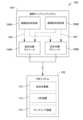
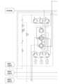
図1~図6Cを概して参照すると、試料をインラインで長距離に亘って自動で分析システムに移送する例示的なシステムが示されている。当該分析システムは、試料を分析するように構成されている。例示的な実施形態では、異なる分析技術を有する複数の分析システムによって、1つ以上の試料が分析され得る。システム100(例えば、分光分析装置と関連するオートサンプラ)は、第1の場所に少なくとも1つの分析システム102を備えている。<Example>
1-6C, an exemplary system for automated in-line long distance transport of samples to an analytical system is shown. The analytical system is configured to analyze the samples. In an exemplary embodiment, one or more samples may be analyzed by multiple analytical systems having different analytical techniques. The system 100 (e.g., an autosampler associated with a spectroscopic analyzer) includes at least one
システム100は、第1の場所から遠隔にある1つ以上の場所(例えば、第2の場所)に、2つ以上の遠隔サンプリングシステム104を備えることもできる。例えば、2つ以上の遠隔サンプリングシステム104は、複数の化学物質の供給源の近傍に配置され得る。化学物質の供給源とは、化学物質貯蔵タンク、化学物質処理タンク(例えば、薬液槽)、化学物質移送ライン又はパイプなど(例えば、分析システム102の第1の位置から遠隔にある)である。化学物質の供給源は、図1に示す遠隔試料供給源106A及び遠隔試料供給源106B、並びに図2に示す遠隔試料供給源A~N 106A~106N(例えば、供給源A~N)のようなものである。The
このような供給源106A~106Nからの化学物質は、分析システム102によって分析され得る。分析システム102は、生産設備用の分析ハブ(例えば、第1の場所)のように、遠隔サンプリングシステム(複数の遠隔サンプリングシステム)104から遠隔に配置され得る。実施例では、遠隔サンプリングシステム104は、2つ以上の遠隔試料供給源106A~106Nと関連して使用するための2つ以上の試料収集装置108A~108Nを有し得る。一実施形態では、遠隔試料供給源106の数と同じ数の試料収集装置108が使用され得る。一実施形態では、試料収集装置108の数は、遠隔試料供給源106の数とは異なる。Chemicals from
また、システム100は、第3の場所、第4の場所などに、1つ以上の遠隔サンプリングシステム104を備え得る。第3の場所及び/又は第4の場所は、第1の場所から遠隔にある。実施例では、遠隔サンプリングシステム104の第3の場所、第4の場所、及び他の場所は、他の遠隔サンプリングシステム104の他の場所の各々から遠隔であり得る。例えば、1つの遠隔サンプリングシステム104が水ライン(例えば、脱イオン水移送ライン)に配置され得る。一方、1つ以上の他の遠隔サンプリングシステム104は、2つ以上の化学物質貯蔵タンク、化学物質処理タンク(例えば、薬液槽)、化学物質移送ライン又はパイプなどを有する場所に配置され得る。The
いくつかの実施形態では、システム100は、第1の場所(例えば、分析システム102の近傍)に、1つ以上の遠隔サンプリングシステム104を備えてもよい。例えば、第1の場所にあるサンプリングシステム104は、分析システム102と結合されたオートサンプラを有してもよい。1つ以上のサンプリングシステム104は、第1の場所、第2の場所、第3の場所、第4の場所などから試料を受け入れるように動作可能であり得る。システム100は、分析のために試料を分析システム102に送達するように動作可能であり得る。システム100は、所与の試料供給源106A~106Nから試料を取得し、選択された試料収集モジュール108A~108Nに試料を移送して、試料をある距離を超えて分析システム102に送達するのに適した構成要素を備えることができる。当該構成要素は、ポンプ、弁、チューブ、センサなどである。In some embodiments, the
本実施形態に係る遠隔サンプリングシステム104は、複数の遠隔試料供給源106A~106Nのうちの1つから、試料を複数の試料収集モジュール108A~108Nのうちの1つに選択可能に提供し、1つ以上の試料を送達(例えば、分析システム102への送達)及び/又は分析のために調製するように構成され得る。このように、本遠隔サンプリングシステム104は、化学物質供給源106A~106Nを対応するセットの遠隔サンプリングモジュール108A~108Nの間で切替え可能にする。The
例えば、図1では、各供給源-モジュール流体接続部109は、遠隔試料供給源106A~106Bと試料収集モジュール108A~108Bとの間の流体流路を提供する。各供給源-モジュール流体接続部109は、このようなユニットの間の選択的な流れ(すなわち、全流路が利用可能であるが必ず使用されるわけではなく、後述する弁の使用によって達成され得る)を概略的に示すために、破線形で示されている。実施形態では、遠隔サンプリングシステム104は、分析システム102から様々な距離(例えば、1m、5m、10m、30m、50m、100m、300m、1000mなど)に配置され得る。For example, in FIG. 1, each source-
遠隔サンプリング装置104は、試料の流れ又は試料供給源106A~106Nからの試料(例えば、廃水、すすぎ水、化学物質、工業薬品などの液体、液体と接触する気体試料及び/又はその混入物など)を収集するように構成された装置(例えば、所与の試料収集モジュール108の一部として)を有し得る。遠隔サンプリングシステム104は、試料供給源から試料を取得し、試料をある距離を超えて分析システム102に送達するのに適した構成要素を備えることができる。当該構成要素は、ポンプ、弁、チューブ、センサなどである。所与の試料収集モジュール108は、特定の試料濃度、添加された試料(spiked samples)、校正曲線などを提供するように、収集された試料を希釈剤、内部標準、キャリアなどを用いて調製するように更に構成されてもよく、すすぎ液(例えば、脱イオン水)ですすぐように構成されてもよい。The
分析システム102は、遠隔サンプリングシステム104と流体結合されている。例えば、分析システム102は、試料収集器110、分析装置112、及び/又はサンプリング装置114を有してもよい。試料収集器110は、試料を分析装置112及び/又はサンプリング装置114に搬送するために、所与の遠隔サンプリングシステム104の試料収集モジュール108A~108Nのうちの1つ以上から試料を収集するように構成され得る。分析システム102は、分析システム102(例えば、ローカルオートサンプラ)近傍の試料を収集して、例えば、分析装置112に送達するように構成されたサンプリング装置114を有してもよい。The
分析システム102は、例えば微量元素濃度、同位体比など(例えば、液体中)を測定するために、試料を分析するように構成された少なくとも1つの分析装置112を有し得る。例えば、分析装置112は、ICP分光分析装置を含み得る。ICP分光分析装置は、誘導結合プラズマ質量分析装置(ICP/ICP-MS)、誘導結合プラズマ原子発光分析装置(ICP-AES)、誘導結合プラズマ光学発光分析装置(ICPOES: Inductively Coupled Plasma Optical Emission Spectrometer)などを含むが、これらに限定されない。実施形態では、分析システム102は、複数の分析装置112(すなわち、1つより多くの分析装置)を有する。例えば、システム100及び/又は分析システム102は、複数のサンプリングループを有し得る。各サンプリングループは、試料の一部を複数の分析装置112に導入する。The
別の例として、システム100及び/又は分析システム102は、単一の試料が複数の分析装置112に速く連続して導入され得るように、多位置弁を有して構成され得る。実施形態では、所与の分析装置112は、ICPMS(例えば、微量金属の測定のため)、ICPOES(例えば、微量金属の測定のため)、イオンクロマトグラフ(例えば、アニオン及びカチオンの測定のため)、液体クロマトグラフ(LC: Liquid Chromatograph)(例えば、有機汚染物質の測定のため)、フーリエ変換赤外分光(FTIR infrared: Fourier-transform Infrared Spectroscopy)(例えば、化学組成及び構造情報の決定のため)、パーティクルカウンタ(例えば、不溶解粒子の検出のため)、水分計(例えば、試料中の水分の検出のため)、ガスクロマトグラフ(GC: gas chromatograph)(例えば、揮発性成分の検出のため)などであり得るが、これらに限定されない。As another example, the
実施形態では、所与の分析装置又は分析器112は、遠隔サンプリングシステム104から遠隔に配置され得る。一実施形態では、所与の分析装置112は、所与の遠隔サンプリングシステム104の近傍にあってもよい。化学物質の切替え又は変更を実行する能力は、分析システム102がサンプリングシステム104の近傍にあるシステム100と同様に、このような構成要素が互いに遠隔にある場合にも利用され得ることが理解される。In an embodiment, a given analytical device or
少なくとも1つの分析器112は、複数の試料収集装置108A~108Nの少なくとも1つから試料の少なくとも1つを受け入れるために、複数の試料収集装置108A~108Nの少なくとも1つに結合されるとともに、各試料収集装置108A~108Nは少なくとも1つの対応する分析器112に接続されることが理解される。一実施形態では、複数の試料収集装置108A~108N又はNよりも小さい数の試料収集装置は、1つの所与の分析器112に流体接続され得る。一実施形態では、各試料収集装置108A~108Nは、各試料収集装置108A~108Nと対応する単一の分析器112を有してもよい。一実施形態では、複数の試料収集システム108の1つ目が1つ目の分析器112の専用にされ、複数の試料収集システム108の別の2つ目が別の2つ目の分析器112の専用にされ、というようにされ得る。It is understood that at least one
システム100及び/又は分析システム102は、ある場所における分析物の濃度を経時的に報知するように構成され得る。いくつかの実施形態では、分析装置112は、試料中の1つ以上の微量金属を検出するように構成されてもよい。他の実施形態では、分析装置112は、イオンクロマトグラフィ用に構成されてもよい。例えば、イオン及び/又はカチオンは、試料中で収集され、クロマトグラフ分析装置112に送達され得る。更なる実施形態では、有機分子、タンパク質などが試料中で収集され、高分解能飛行時間型(HR-ToF: High-Resolution Time-of-Flight)質量分析装置112(例えば、ネブライザ(図示せず)が使用される)に移送され得る。The
したがって、本明細書に記載のシステムは、様々な用途に使用され得る。当該様々な用途とは、製薬用途(例えば、複数の製薬反応装置に接続された中核的な質量分析装置を伴う)、1つ以上の廃棄の流れの廃棄物モニタリング、半導体製造設備などを含むが、必ずしもこれらに限定されない。例えば、廃棄の流れは、汚染物質について連続的に監視され、汚染物質が検出されたときにタンクに導かれてもよい。別の例として、1つ以上の化学物質の流れは、分析システム102に関連付けられた1つ以上の遠隔サンプリングシステム104によって得られた試料の分析によって、連続的に監視され得る。そのために、化学物質の流れの各々に対して、汚染限度が設定され得る。特定の流れに汚染限度を超える汚染物質が検出されると、システム100は、警告を提供できる。Thus, the systems described herein may be used in a variety of applications, including, but not limited to, pharmaceutical applications (e.g., involving a core mass spectrometer connected to multiple pharmaceutical reactors), waste monitoring of one or more waste streams, semiconductor manufacturing facilities, and the like. For example, a waste stream may be continuously monitored for contaminants and directed to a tank when a contaminant is detected. As another example, one or more chemical streams may be continuously monitored by analysis of samples obtained by one or more
遠隔サンプリングシステム104は、ガス供給(図示せず)と選択的に結合するように構成されることができ、ガスを第2の場所(あるいは、第3の場所、第4の場所など)から第1の場所に移送するように構成され得る。このようにして、遠隔サンプリングシステム104によって供給される液体試料セグメントは、ガスの流れに収集され、ガス圧の試料移送によって分析システム102の場所に移送され得る。いくつかの実施形態では、ガスの収集の流れは、不活性ガスを含み得る。当該不活性ガスは、窒素ガス、アルゴンガスなどを含むが、必ずしもこれらに限定されない。The
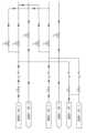
図3A~図3B及び図4に示す例示的な実施形態は、流れを試料収集モジュール108A~108Nの所与のセットに供給するときに、異なる試料供給源106A~106Nが特にどのように関連付けられるかという点の更なる詳細を示す。図3A~図3Bに関し、遠隔試料供給源106A,106Bは、所与の試料が対応する試料収集モジュール又はサンプリングユニット108A,108Bに選択可能に流れることができるように、供給源-モジュール流体接続部109を介して相互接続され得る。供給源-モジュール流体接続部109は、流体ライン又は他の配管を有し、当該流体ライン又は他の配管を介して望まれる調整された流れが実現する。当該流体ライン又は他の配管は、1つ以上の手動弁120、逆止弁122、空気圧弁124、及び/又は圧力調整器126を有してもよい。3A-3B and 4 provide further details of how the
水供給源128(例えば、脱イオン水(DIW: Deionized Water)又は他の形態の水を供給する)は、各水ライン130を介して、対応する供給源-モジュール流体接続部109と流体結合され得る。このような水ライン130は、例えば1つ以上の手動弁120及び/又は逆止弁122を有してもよく、当該水ライン130を通じて望まれる供給源-モジュール流体接続部109に向かう水の調整を容易にする。一実施形態では、対応する手動弁120は、所与の供給源-モジュール流体接続部109の水の流れ(例えば、DIWによる)を調整するために使用される。いくつかの実施形態では、例えば、弁の電子制御を容易にするために、所与の水ライン130内に他のタイプの弁(例えば、空気圧弁124)が設けられてもよい。水供給源128は、所与の供給源-モジュール流体接続部109の洗い流し又はすすぎ、及び/又は所与の試料の希釈に役立つように使用されてもよい。A water source 128 (e.g., providing deionized water (DIW) or other forms of water) may be fluidly coupled to a corresponding source-
所与の供給源-モジュール流体接続部109は、当該供給源-モジュール流体接続部109に結合された廃棄流れライン132を更に有し得る。供給源-モジュール流体接続部109からの流れは、廃棄流れライン132によって導かれてもよい。例えば、廃棄流れライン132には、少なくとも1つの空気圧弁124及び/又は他のタイプの弁が設けられてもよく、それを通じる流体が選択的に流れる(例えば、廃棄場所へ)ことが可能になる。実施形態では、所与の廃棄流れライン132に関連する空気圧弁124は、対応する供給源-モジュール流体接続部109のDIWによる洗い流しの間に開放されてもよい。A given source-
空気圧弁124は、それに関連する様々な特徴を有してもよい。一実施形態では、全ての空気圧弁124は、明示的に作動及び開放されない限り、通常閉鎖(NC)されている。実施形態では、空気圧弁124は、制御器によって独立して制御され、システム100において化学物質の選択を許容するように構成されている。一実施形態では、空気圧弁124は、システム100の電源オフ及び/又は緊急イベントが起きたときに、自動的に閉鎖されるようになっている。複数の遠隔試料収集モジュール108が存在する実施形態では、空気圧弁124の所与のセットは、各試料収集モジュール108に対応し、所与の試料収集モジュール108によってどの供給源の物質(例えば、化学物質)を送達すべきかを制御してもよい。一実施形態では、全ての空気圧弁124は、独立して制御されている。図3A~図3Bに示すような、化学物質の切替え及びDIW洗い流しのオプションを有する実施形態では、所与の遠隔試料システムに最大2つの試料部(sample points)が存在する。The pneumatic valves 124 may have various features associated with them. In one embodiment, all pneumatic valves 124 are normally closed (NC) unless explicitly actuated and opened. In an embodiment, the pneumatic valves 124 are independently controlled by a controller and configured to allow chemical selection in the
図4に示す実施形態は、第1の試料S1及び/又は第2の試料S2を送達するための第1ペアの供給源-モジュール流体接続部109A,109Bと、第3の試料S3及び/又は第4の試料S4を送達するための第2ペアの供給源-モジュール流体接続部109C,109Dとを、遠隔サンプリングシステム104の一部として提供する。図4の実施形態は、各供給源-モジュール流体接続部109A~109Dに水(例えば、DIW)の流れを選択的に供給するように構成されている。また、各供給源-モジュール流体接続部109A~109Dは、対応する廃棄流れライン132A~132Dと流体結合される。図4の実施形態は、図3の実施形態と同様に、ポンプ、弁、チューブ、センサなどの構成要素を含み得る。当該構成要素は、対応する試料供給源106A~106Dから試料S1~S4を取得して、当該試料S1~S4を所与の試料収集モジュール108A~108D(図4には明示的には示されない)に向かって送達するのに適する。The embodiment shown in FIG. 4 provides a first pair of source-module fluid connections 109A, 109B for delivering a first sample S1 and/or a second sample S2, and a second pair of source-module fluid connections 109C, 109D for delivering a third sample S3 and/or a fourth sample S4, as part of a
システム100は、包囲型サンプリングシステムとして実施され得る。包囲型サンプリングシステムでは、供給源-モジュール流体接続部109(例えば、試料移送ライン)内のガス及び試料は、周囲環境に曝露されない。例えば、ハウジング及び/又は被覆部(sheath)(図示せず)は、システム100の1つ以上の構成要素を囲むことができる。いくつかの実施形態では、遠隔サンプリングシステム104の1つ以上の試料ラインは、試料の送達の間に洗浄されてもよい。さらに、1つ以上の供給源-モジュール流体接続部109は、試料の間で洗浄されてもよい(例えば、洗浄液が使用される)。The
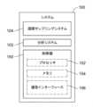
図5に関し、構成要素の一部又は全てを有するシステム100は、制御器150によってコンピュータ制御の下で動作することができる。制御器150は、プロセッサ152、メモリ154、及び/又は通信インターフェース156を有してもよい。例えば、分析システム102、遠隔サンプリングシステム104、弁(例えば、空気圧弁124)、ポンプ、及び/又は検出器など、システムの1つ以上の構成要素は、試料(例えば、図4に示すS1~S4)の収集、送達、及び/又は分析を制御するために制御器150と結合され得る。例えば、制御器150は、所与の供給源-モジュール流体接続部109内に配置された1つの空気圧弁124を切り替えて、どの試料が当該空気圧弁124及び/又は同じライン109又は対応する廃棄ライン132に配置された他の空気圧弁124に流されるかを選択的に選ぶように構成され得る。このことにより、空気圧弁124を通じる流れを対応する試料収集モジュール若しくはサンプリングユニット108に向けるか、又は対応する廃棄ライン132に通じるかということが決定される。制御器150及びその構成要素の詳細は、以下の「制御システム」と題される部分でより詳細に説明される。5, the
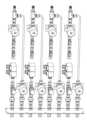
図6A~図6Cに示す遠隔サンプリングシステム204は、ここに記載のものを除き、機能及び構成要素において遠隔サンプリングシステム104と同様である。遠隔サンプリングシステム204は、概して、異なる試料供給源206A~206Cが試料収集モジュール108A~108Cの所与のセットへの選択可能な流れを提供するときに特に連結され得る方法を示す。図6A~図6Cに関し、遠隔試料供給源206A~206Cは、対応する試料収集モジュール又はサンプリングユニット108A~108Cへの所与の試料の選択可能な流れを許容するように、供給源-モジュール流体接続部209を介して相互接続され得る。供給源-モジュール流体接続部209は、流れライン又は他の配管で構成されてもよい。当該流れライン又は他の配管は、それを通じる調整された望まれる流れを実現するための、1つ以上の手動弁220、逆止弁222、空気圧弁224、圧力調整器226、及び/又はマルチポート弁227と、他の成分(例えば、希釈剤など)を望まれるように流れに導入しやすくするための複数のシリンジ229と、を有する。The remote sampling system 204 shown in Figures 6A-6C is similar in function and components to the
水供給源228(例えば、脱イオン水(DIW)又は他の形態の水を供給する)は、各水ライン230を介して、対応する供給源-モジュール流体接続部209と流体結合される。このような水ライン230は、例えば、1つ以上の手動弁220及び/又は逆止弁22を保持しており、それを通じて望まれる供給源-モジュール流体接続部209に向かう水の制御を容易にしてもよい。所与の供給源-モジュール流体接続部209は、そこに結合された廃棄流れライン232を更に有する。供給源-モジュール流体接続部209からの流れは、廃棄流れライン232を通じて導かれ得る。例えば、廃棄流れライン232には、少なくとも1つの空気圧弁224及び/又は他のタイプの弁が設けられてもよく、それを通じる流体が選択的に流れる(例えば、廃棄場所へ)ことが可能になる。遠隔サンプリングシステム204に関連する部品のうち、遠隔サンプリングシステム104と関連する部品と同様の番号が付されたもの(例えば、流体接続部109,209)は、ここに記載しない限り、同様の構造及び/又は機能を有することが期待され得る。A water source 228 (e.g., providing deionized water (DIW) or other forms of water) is fluidly coupled to a corresponding source-module fluid connection 209 via each water line 230. Such water lines 230 may, for example, carry one or more manual valves 220 and/or check valves 220 to facilitate control of water directed therethrough to the desired source-module fluid connection 209. A given source-module fluid connection 209 further has a waste flow line 232 coupled thereto. Flow from the source-module fluid connection 209 may be directed through the waste flow line 232. For example, the waste flow line 232 may be provided with at least one pneumatic valve 224 and/or other type of valve to selectively allow fluid to flow therethrough (e.g., to a waste location). Components associated with remote sampling system 204 that are similarly numbered as components associated with remote sampling system 104 (e.g.,
遠隔サンプリングシステム204には、遠隔サンプリングシステム104と異なり得る領域がいくつか存在する。一つは、様々な流体接続部209を通じる試料及び/又は他の成分の選択的な流れを容易にするために、複数のマルチポート弁227が使用されることである。マルチポート弁227の使用により、システム104において様々な適切な配管のオプション(例えば、弁、マニホールドなど)を使用して、試料収集モジュール108A~108Cのいずれかへの選択可能な流れ(例えば、望まれる試料)をもたらすことが可能になる。このようなマルチポート弁227は、所与の弁位置において望まれる流入及び/又は流出を実現するように、当該マルチポート弁227に関連する任意の数(例えば、3,4,5,6,7など)のポートを有してもよい。また、図示のように、望まれる流れの機能を実現するように、所与の場所においてマルチポート弁227の組合せが用いられ得る。制御器150は、遠隔サンプリングシステム204の動作を制御する(例えば、各マルチポート弁227を通じる選択的な流れ)ために使用され得ることが理解される。他の異なる点は、望まれるように他の成分(例えば、希釈剤など)を流れに選択可能に導入しやすくするためのシリンジ229が使用される点である。There are several areas in which the remote sampling system 204 may differ from the
最後に、図6A~図6Cは、様々な廃棄流れライン232が流体的に相互接続されていることを示す。このことは、廃棄ラインの流れ(例えば、再利用、廃棄などに向かう)の管理を補助できる。しかしながら、他の廃棄流れライン232は、代わりに使用されることができ、なお本開示の範囲内にあることが理解される。さらに、図3A~図3B、図4、及び図6の実施形態に示す要素は、適切であるように混合及び調和されることができ、このような組合せは本開示の範囲内にあるとみなされることが理解される。Finally, FIGS. 6A-6C show that the various waste flow lines 232 are fluidly interconnected. This can aid in managing the flow of the waste lines (e.g., to recycle, waste, etc.). However, it is understood that other waste flow lines 232 can be used instead and still be within the scope of the present disclosure. Additionally, it is understood that the elements shown in the embodiments of FIGS. 3A-3B, 4, and 6 can be mixed and matched as appropriate, and such combinations are considered to be within the scope of the present disclosure.
<制御システム>
構成要素の一部又は全てを含むシステム100は、制御器150によってコンピュータ制御の下で動作できる。制御器150は、プロセッサ152、メモリ154、及び/又は通信インターフェース156を有してもよい。例えば、プロセッサ152は、システム100と共に含まれるか又はシステム100内に含まれることができ、ソフトウェア、ファームウェア、ハードウェア(例えば、固定論理回路)、手動処理、又はそれらの組合せを使用して、本明細書に記載のシステムの構成要素及び機能を制御できる。本明細書で使用される「制御器」、「機能」、「サービス」、及び「論理」との用語は、概して、システムの制御と関連して、ソフトウェア、ファームウェア、ハードウェア、又はソフトウェア、ファームウェア、若しくはハードウェアの組合せを表す。ソフトウェアの実施の場合、モジュール、機能、又はロジックは、プロセッサ(例えば、中央処理装置(CPU)又は複数の中央処理装置(CPUs))で実行されたときに特定のタスクを実行するプログラムコードを表す。プログラムコードは、1つ以上のコンピュータ可読メモリ装置(例えば、内部メモリ及び/又は1つ以上の有形媒体)などに記憶され得る。本明細書に記載の構造、機能、アプローチ、及び技術は、様々なプロセッサを有する様々な商用コンピューティングプラットフォーム上で実施され得る。<Control System>
The
いくつかの実施形態では、制御器150は、第2の場所などの遠隔地にある表示器と通信可能に結合され、第1の場所において受け入れられる試料が不足したときに、第2の場所で表示(例えば、警告)を提供する。当該表示は、追加の試料収集及び送達を開始する(例えば、自動的に)ために使用され得る。いくつかの実施形態では、表示は、操作者に警告(例えば、1つ以上の表示灯、表示読み出し、それらの組合せなどによる)を提供する。さらに、表示は、1つ以上の予め決定された条件(例えば、複数の試料が取り損ねられた)に基づいて時間決め(timed)及び/又は開始され得る。また、いくつかの実施形態では、表示器は、遠隔のサンプリング場所で測定された条件に基づいて起動されることもできる。例えば、第2の場所における検出器は、試料が遠隔サンプリングシステム104内で提供されているときを判定するために使用され得る。表示器は、試料が収集されないときに起動されることができる。In some embodiments, the
制御器150と関連するプロセッサ152は、制御器150のために処理機能を提供する。当該プロセッサ152は、任意の数のプロセッサ、マイクロ制御器、又は他の処理システムと、データ及び制御器150によってアクセス又は生成される他の情報を記憶するための内在メモリ又は外部メモリと、を有し得る。プロセッサ152は、本明細書に記載の技術を実現する1つ以上のソフトウェアプログラムを実行できる。プロセッサ152は、本明細書に採用された、プロセッサの形成物質及び処理機構によって限定されない。そのようなプロセッサは、半導体(複数の半導体)及び/又はトランジスタ(例えば、電子集積回路(IC: integrated circuit)部品を使用する)などによって実現され得る。A
制御器150のメモリ154は、有形のコンピュータ可読記憶媒体、及び、場合により、本明細書に記載の機能を実行するための制御器150の他の構成要素の例である。当該有形のコンピュータ可読記憶媒体は、本明細書に記載の機能を実行するために、ソフトウェアプログラム及び/又はコードセグメントなどの制御器150の動作に関連する様々なデータ、又は、プロセッサ152及び場合によっては制御器150に命令する他のデータを記憶するための記憶機能を提供する。したがって、メモリ154は、システム100(その構成要素を含む)を動作させるための命令のプログラムなどのようなデータを記憶できる。なお、単一のメモリが説明されているが、幅広い種類及び組合せのメモリ(例えば、有形の非一時的メモリ)が採用可能であることに留意されたい。メモリ154は、プロセッサ152と一体化されたメモリ、スタンドアロンメモリを構成するメモリ、又は両方の組合せであり得る。The
メモリ154は、ランダムアクセスメモリ(RAM)、リードオンリーメモリ(ROM)、フラッシュメモリ(例えば、SD(secure digital)メモリカード、mini-SDメモリカード、及び/又はmicroSDメモリカード)、磁気メモリ、光学メモリ、ユニバーサルシリアルバス(USB)メモリ装置、ハードディスクメモリ、外部メモリなどの、取り外し可能なメモリ部品及び取り外し不可能なメモリ部品を含み得るが、これらに限定されない。実施例では、システム100及び/又はメモリ154は、SIM(subscriber identity module)カード、USIM(universal subscriber identity module)カード、UICC(universal integrated circuit card)などによって提供されるメモリ154のような、取り外し可能なICC(integrated circuit card)メモリを含み得る。
制御器150の通信インターフェース156は、システムの構成要素と通信するように動作的に構成されている。例えば、通信インターフェース156は、システム100内の記憶装置へのデータの送信、システム100における記憶装置からのデータの取り出しなどを行うように構成され得る。また、通信インターフェース156は、システム100の構成要素とプロセッサ152との間のデータ転送(例えば、制御器150と通信結合された装置から受け入れた入力をプロセッサ152に伝達する)を容易にするために、プロセッサ152と通信結合されている。なお、通信インターフェース156が制御器150の構成要素として説明されているが、通信インターフェース156の1つ以上の構成要素は、有線接続及び/又は無線接続を介してシステム100に通信結合された外部の構成要素として実施され得ることに留意されたい。また、システム100は、1つ以上の入力/出力(I/O)装置(例えば、通信インターフェース156を介する)を備えることができ、及び/又は、当該入力/出力装置に接続されることができる。当該入力/出力装置は、ディスプレイ、マウス、タッチパッド、キーボードなどを含むが、これらに限定されない。The
通信インターフェース156及び/又はプロセッサ152は、様々な異なるネットワークと通信するように構成され得る。様々な異なるネットワークは、3Gセルラネットワーク、4Gセルラネットワーク、又はGSM(global system for mobile communications)ネットワークなどの広域セルラ電話ネットワーク、Wi-Fiネットワーク(例えば、IEEE 802.11ネットワーク規格によって運用されるワイヤレスローカルエリアネットワーク(WLAN))などの無線コンピュータ通信ネットワーク、インターネット、広域ネットワーク(WAN)、ローカルエリアネットワーク(LAN)、パーソナルエリアネットワーク(PAN)(例えば、IEEE 802.15ネットワーク規格によって運用されるワイヤレスパーソナルエリアネットワーク(WPAN))、公衆電話網、エクストラネット、イントラネットなどを含むが、これらに限定されない。しかしながら、この列挙は、例のみのために提供されるものであって、本開示を限定することを意図するものではない。さらに、通信インターフェース156は、単一のネットワーク又は複数のネットワークと、異なるアクセスポイントにまたがって通信するように構成され得る。The
また、遠隔サンプリングシステムにおいて試料の汚染を検出するための方法も説明される。実施例では、遠隔サンプリングシステム104は、試料収集装置108A~108Nによって遠隔試料供給源106A~106Nから試料を取り入れる。いくつかの実施例では、試料収集装置108A~108Nは、試料供給源106A~106Nのいずれかから1つ以上の試料を受け入れるために、試料供給源106A~106Nのいずれかに選択的に流体結合され得る。試料は、第1の流体接続路(例えば、第1の供給源-流体接続部109)を通じて分析システム102に導かれる。分析システム102は、試料中に汚染物質が存在するか否かを検出する。汚染物質の存在が検出されると、試料は、対応する試料供給源106A~106Nから、第2の遠隔サンプリングシステム及び第2の流体接続路(例えば、第2の供給源-流体接続部109)を通じて分析システム102に再び導かれる。Also described is a method for detecting contamination of a sample in a remote sampling system. In an embodiment, the
次いで、分析システム102は、第2の接続路を通じて受け入れた試料に汚染物質が存在するか否かを検出する。いくつかの実施例では、分析システム102は、試料が汚染されているか又は第1の遠隔サンプリングシステムが汚染されているかを判定するために、汚染物質の程度を比較する。いくつかの実施例では、分析システム102は、汚染物質が予め決められた程度を超えているか否かを判定する。汚染物質が予め決められた程度を超えているとき、試料は、第2の接続路を通じて再び導かれる。いくつかの実施例では、検出された汚染物質が予め決められた程度を超えると、警告が発せられる。いくつかの実施例では、システム100は、試料の収集、送達、及び/又は分析を制御するように、制御器150を介して動作する。例えば、制御器150は、流体接続路を通じて試料を選択的に導くように動作可能である。The
<結言>
実施例において、本明細書に記載の構造、技術、アプローチなどは、様々な分析装置によって利用されてもよい。したがって、本明細書ではシステムが説明されているが、説明された技術、アプローチ、構造などは、様々な分析装置によって利用されてもよい。これらの装置は、限られた機能(例えば、薄い装置)を有して構成されてもよいし、ロバストな機能(例えば、厚い装置)を有して構成されてもよい。したがって、装置の機能は、装置のソフトウェア又はハードウェア供給源に関連し、例えば、処理能力、メモリ(例えば、データ記憶能力)、分析能力などに関連し得る。<Conclusion>
In embodiments, the structures, techniques, approaches, etc. described herein may be utilized by a variety of analytical devices. Thus, although systems are described herein, the described techniques, approaches, structures, etc. may be utilized by a variety of analytical devices. These devices may be configured with limited functionality (e.g., thin devices) or with robust functionality (e.g., thick devices). Thus, the functionality of a device may relate to the software or hardware resources of the device, and may relate to, for example, processing power, memory (e.g., data storage capabilities), analytical capabilities, etc.
一般的に、本明細書に記載の機能のうちの任意のものは、ハードウェア(例えば、集積回路などの固定論理回路)、ソフトウェア、ファームウェア、手動処理、又はそれらの組合せによって実施可能である。したがって、前記の開示で説明されたブロックは、概して、ハードウェア(例えば、集積回路などの固定論理回路)、ソフトウェア、ファームウェア、又はそれらの組合せを表す。ハードウェア構成の例では、前記の開示で説明された様々なブロックは、他の機能性と共に集積回路として実施されてもよい。そのような集積回路は、所与のブロック、システム、又は回路の機能の全てを含んでもよく、又はブロック、システム、又は回路の機能の一部を含んでもよい。さらに、ブロック、システム、又は回路の要素は、複数の集積回路にまたがって実装されてもよい。このような集積回路は、様々な集積回路で構成されてもよい。様々な集積回路とは、モノリシック集積回路、フリップチップ集積回路、マルチチップモジュール集積回路、及び/又は混合信号集積回路を含むが、必ずしもこれらに限定されない。In general, any of the functionality described herein may be implemented by hardware (e.g., fixed logic circuitry such as integrated circuits), software, firmware, manual processing, or a combination thereof. Thus, the blocks described in the disclosure above generally represent hardware (e.g., fixed logic circuitry such as integrated circuits), software, firmware, or a combination thereof. In an example of a hardware configuration, the various blocks described in the disclosure above may be implemented as an integrated circuit along with other functionality. Such an integrated circuit may include all of the functionality of a given block, system, or circuit, or may include a portion of the functionality of the block, system, or circuit. Furthermore, elements of a block, system, or circuit may be implemented across multiple integrated circuits. Such an integrated circuit may be composed of various integrated circuits, including, but not necessarily limited to, monolithic integrated circuits, flip-chip integrated circuits, multi-chip module integrated circuits, and/or mixed signal integrated circuits.
ソフトウェアの実施の例では、前記の開示で説明された様々なブロックは、プロセッサ上で実行されたときに特定のタスクを実行する実行可能な命令(例えば、プログラムコード)を表す。これらの実行可能な命令は、1つ以上の有形のコンピュータ可読媒体に記憶され得る。いくつかのこのような例では、システム、ブロック、又は回路の全体は、そのソフトウェア又はファームウェアの等価物によって実施されてもよい。他の例では、所与のシステム、ブロック、又は回路の一部は、ソフトウェア又はファームウェアで実施される一方で、他の部分はハードウェアで実施されてもよい。In software implementation examples, the various blocks described in the disclosure above represent executable instructions (e.g., program code) that, when executed on a processor, perform particular tasks. These executable instructions may be stored on one or more tangible computer-readable media. In some such examples, the entire system, block, or circuit may be implemented by its software or firmware equivalent. In other examples, portions of a given system, block, or circuit may be implemented in software or firmware, while other portions may be implemented in hardware.
主題は、構造的特徴及び/又は方法の操作に特有の言語で説明されている。しかしながら、添付の特許請求の範囲に規定される主題は、前記の特有の特徴又は行為に必ずしも限定されないことが理解される。むしろ、前記の特有の特徴及び行為は、特許請求の範囲の実施の例示的な形態として開示される。Subject matter has been described in language specific to structural features and/or method operations. It will be understood, however, that the subject matter defined in the appended claims is not necessarily limited to such specific features or acts. Rather, the specific features and acts are disclosed as exemplary forms of implementing the claims.
Claims (20)
Translated fromJapanese複数の試料収集装置によって複数の試料供給源のうちの1つから試料を取り入れることであって、複数の前記試料収集装置が、複数の前記試料供給源のいずれかから前記試料を受け入れるために、複数の前記試料供給源のいずれかに選択的に流体結合されることと、
前記試料を複数の接続路のうちの1つを通じて少なくとも1つの分析器に導くことと、
少なくとも1つの前記分析器によって、前記試料中に汚染物質が存在するか否かを検知することと、
前記試料中に存在する前記汚染物質の検知に基づき、前記試料を複数の前記試料供給源のうちの対応する1つから、複数の前記接続路のうち2つ目の前記接続路を通じて、少なくとも1つの前記分析器に導き直すことと、
少なくとも1つの前記分析器によって、複数の前記接続路のうち2つ目の前記接続路を通じて受け入れた前記試料中に前記汚染物質が存在するか否かを検知することと、
を含む、方法。 1. A method for detecting contamination of a sample in a remote sampling system, comprising:
acquiring a sample from one of a plurality of sample sources by a plurality of sample collectors, the plurality of sample collectors being selectively fluidly coupled to any of the plurality of sample sources for receiving the sample from any of the plurality of sample sources;
conducting the sample through one of a plurality of connections to at least one analyzer;
detecting, by at least one of the analyzers, whether a contaminant is present in the sample; and
redirecting the sample from a corresponding one of the plurality of sample sources through a second one of the plurality of connections to at least one of the analyzers based on detection of the contaminant present in the sample;
detecting, with at least one of the analyzers, whether the contaminant is present in the sample received through a second of the plurality of connections;
A method comprising:
少なくとも1つの分析器と、
前記遠隔サンプリングシステム及び少なくとも1つの前記分析器に結合された制御器と、
を備え、
前記遠隔サンプリングシステムは、
対応する試料を供給するための複数の試料供給源と、
複数の前記試料供給源のいずれかから少なくとも1つの前記試料を受け入れるために、複数の前記試料供給源のいずれかに選択的に流体結合された複数の試料収集装置と、
複数の収集装置に選択的に結合された複数の流体接続路と、
を有し、
少なくとも1つの前記分析器は、複数の前記試料収集装置のうち少なくとも1つから前記試料のうち少なくとも1つを受け入れるために、複数の前記試料収集装置のうち少なくとも1つに結合され、
各試料収集装置は、複数の前記流体接続路を介して少なくとも1つの対応する前記分析器に接続され、
前記制御器は、
前記試料を複数の前記流体接続路のうちの1つを通じて少なくとも1つの前記分析器に導くように前記遠隔サンプリングシステムを制御し、
少なくとも1つの前記分析器に、前記試料中に汚染物質が存在するか否かを検知させ、
前記試料中に存在する前記汚染物質の検知に基づき、前記試料を複数の前記試料供給源のうちの対応する1つから、複数の前記流体接続路のうち2つ目の前記流体接続路を通じて、少なくとも1つの前記分析器に導き直すように、前記遠隔サンプリングシステムを制御し、
少なくとも1つの前記分析器に、複数の前記流体接続路のうち2つ目の前記流体接続路を通じて受け入れた前記試料中に前記汚染物質が存在するか否かを検知させる、
システム。 A remote sampling system;
At least one analyzer;
a controller coupled to the remote sampling system and to at least one of the analyzers;
Equipped with
The remote sampling system comprises:
a plurality of sample sources for providing corresponding samples;
a plurality of sample collection devices selectively fluidly coupled to any of the plurality of sample sources for receiving at least one of the samples from any of the plurality of sample sources;
a plurality of fluid connections selectively coupled to a plurality of collection devices;
having
at least one of the analyzers is coupled to at least one of the sample collection devices to receive at least one of the samples from at least one of the sample collection devices;
each sample collection device is connected to at least one corresponding analyzer via a plurality of said fluid connections;
The controller includes:
controlling the remote sampling system to direct the sample through one of a plurality of the fluid connections to at least one of the analyzers;
causing at least one of the analyzers to detect whether a contaminant is present in the sample;
controlling the remote sampling system to redirect the sample from a corresponding one of the plurality of sample sources through a second one of the plurality of fluid connections to at least one of the analyzers based on detection of the contaminant present in the sample;
causing at least one of the analyzers to detect whether the contaminant is present in the sample received through a second of the plurality of fluid connections;
system.
Applications Claiming Priority (3)
| Application Number | Priority Date | Filing Date | Title |
|---|---|---|---|
| US201962909503P | 2019-10-02 | 2019-10-02 | |
| US62/909,503 | 2019-10-02 | ||
| PCT/US2020/053282WO2021067273A1 (en) | 2019-10-02 | 2020-09-29 | Remote automated chemical crossover system for use with an automated sampling device |
Publications (2)
| Publication Number | Publication Date |
|---|---|
| JP2022550205A JP2022550205A (en) | 2022-11-30 |
| JP7514303B2true JP7514303B2 (en) | 2024-07-10 |
Family
ID=75274949
Family Applications (1)
| Application Number | Title | Priority Date | Filing Date |
|---|---|---|---|
| JP2022520199AActiveJP7514303B2 (en) | 2019-10-02 | 2020-09-29 | Remote automated chemical switching system for use with automated sampling equipment. |
Country Status (6)
| Country | Link |
|---|---|
| US (3) | US11703518B2 (en) |
| JP (1) | JP7514303B2 (en) |
| KR (1) | KR20220071202A (en) |
| CN (1) | CN114502963B (en) |
| TW (1) | TW202127506A (en) |
| WO (1) | WO2021067273A1 (en) |
Families Citing this family (2)
| Publication number | Priority date | Publication date | Assignee | Title |
|---|---|---|---|---|
| US12285711B1 (en)* | 2019-10-02 | 2025-04-29 | Combat Capabilities Development Command, Chemical Biological Center | Automatic sample collector and extractor |
| TWI748675B (en)* | 2020-10-06 | 2021-12-01 | 汎銓科技股份有限公司 | A remote control method of sample preparation and/or sample analysis |
Citations (3)
| Publication number | Priority date | Publication date | Assignee | Title |
|---|---|---|---|---|
| JP2001272321A (en) | 2000-03-27 | 2001-10-05 | Yokogawa Electric Corp | Analyzer with decontamination function |
| WO2012145606A2 (en) | 2011-04-20 | 2012-10-26 | Swagelok Company | Fluid processing systems and sub-systems |
| JP2019070638A (en) | 2017-09-07 | 2019-05-09 | エレメンタル・サイエンティフィック・インコーポレイテッドElemental Scientific, Inc. | Automatic system for remote in-line concentration of super-low concentration component in pure chemical agent |
Family Cites Families (21)
| Publication number | Priority date | Publication date | Assignee | Title |
|---|---|---|---|---|
| US4119120A (en)* | 1976-11-29 | 1978-10-10 | Beckman Instruments, Inc. | Fluid switch |
| US4526754A (en)* | 1982-07-30 | 1985-07-02 | Technicon Instruments Corporation | Sample transport system |
| US4855110A (en)* | 1987-05-06 | 1989-08-08 | Abbott Laboratories | Sample ring for clinical analyzer network |
| US5492831A (en)* | 1994-11-15 | 1996-02-20 | Lachat Instruments | Shared peripheral analytical system |
| JP2002243593A (en)* | 2001-02-15 | 2002-08-28 | Nippon Sanso Corp | Analysis system and analysis method |
| US7096750B2 (en)* | 2004-04-06 | 2006-08-29 | Universal Analyzers, Inc. | Sequencing and averaging multiple sample system |
| US20060160239A1 (en)* | 2005-01-14 | 2006-07-20 | Sung-Jae Lee | Method of measuring a level of contamination in a chemical solution and systems thereof |
| WO2006099337A2 (en)* | 2005-03-10 | 2006-09-21 | Aircuity, Inc. | Multipoint air sampling system having common sensors to provide blended air quality parameter information for monitoring and building control |
| JP2008026187A (en) | 2006-07-21 | 2008-02-07 | National Institute Of Advanced Industrial & Technology | Gas sampling device |
| JP2011064537A (en)* | 2009-09-16 | 2011-03-31 | Sysmex Corp | Specimen processing device |
| US8371181B2 (en)* | 2009-12-21 | 2013-02-12 | Elemental Scientific, Inc. | Continuous flow pump |
| US20130146479A1 (en) | 2010-05-21 | 2013-06-13 | Antec Leyden B.V. | Analytical apparatus comprising an electrochemical flow cell and a structure elucidation spectrometer |
| EP2450711A1 (en)* | 2010-11-03 | 2012-05-09 | F. Hoffmann-La Roche AG | Analaysis system for analyzing biological samples |
| MY157253A (en)* | 2011-02-17 | 2016-05-31 | Petroliam Nasional Berhad Petronas | Sample capture system and methods of use |
| US9760685B2 (en)* | 2011-05-16 | 2017-09-12 | Trimble Inc. | Telematic microfluidic analysis using handheld device |
| US10585075B2 (en)* | 2014-02-27 | 2020-03-10 | Elemental Scientific, Inc. | System for collecting liquid samples |
| JP6672180B2 (en)* | 2014-02-27 | 2020-03-25 | エレメンタル・サイエンティフィック・インコーポレイテッドElemental Scientific, Inc. | System for collecting liquid samples from remote locations |
| US10373838B2 (en) | 2015-12-08 | 2019-08-06 | Elemental Scientific, Inc. | Automatic sampling of hot phosphoric acid for the determination of chemical element concentrations and control of semiconductor processes |
| JP6730056B2 (en) | 2016-03-29 | 2020-07-29 | 株式会社コベルコ科研 | Method and apparatus for analyzing generated gas of power storage device |
| US10948470B2 (en)* | 2016-04-29 | 2021-03-16 | TricornTech Taiwan | System and method for in-line monitoring of airborne contamination and process health |
| US10921295B2 (en)* | 2017-09-08 | 2021-02-16 | Elemental Scientific, Inc. | Automated system for detection of silicon species in phosphoric acid |
- 2020
- 2020-09-29JPJP2022520199Apatent/JP7514303B2/enactiveActive
- 2020-09-29CNCN202080069730.0Apatent/CN114502963B/enactiveActive
- 2020-09-29WOPCT/US2020/053282patent/WO2021067273A1/ennot_activeCeased
- 2020-09-29USUS17/036,863patent/US11703518B2/enactiveActive
- 2020-09-29KRKR1020227010588Apatent/KR20220071202A/enactivePending
- 2020-09-30TWTW109134314Apatent/TW202127506A/enunknown
- 2023
- 2023-05-23USUS18/200,711patent/US11971421B2/enactiveActive
- 2024
- 2024-03-18USUS18/608,274patent/US20240302392A1/enactivePending
Patent Citations (3)
| Publication number | Priority date | Publication date | Assignee | Title |
|---|---|---|---|---|
| JP2001272321A (en) | 2000-03-27 | 2001-10-05 | Yokogawa Electric Corp | Analyzer with decontamination function |
| WO2012145606A2 (en) | 2011-04-20 | 2012-10-26 | Swagelok Company | Fluid processing systems and sub-systems |
| JP2019070638A (en) | 2017-09-07 | 2019-05-09 | エレメンタル・サイエンティフィック・インコーポレイテッドElemental Scientific, Inc. | Automatic system for remote in-line concentration of super-low concentration component in pure chemical agent |
Also Published As
| Publication number | Publication date |
|---|---|
| US20230375579A1 (en) | 2023-11-23 |
| JP2022550205A (en) | 2022-11-30 |
| WO2021067273A1 (en) | 2021-04-08 |
| KR20220071202A (en) | 2022-05-31 |
| US20240302392A1 (en) | 2024-09-12 |
| CN114502963B (en) | 2025-08-26 |
| CN114502963A (en) | 2022-05-13 |
| TW202127506A (en) | 2021-07-16 |
| WO2021067273A8 (en) | 2022-04-21 |
| US20210102963A1 (en) | 2021-04-08 |
| US11703518B2 (en) | 2023-07-18 |
| US11971421B2 (en) | 2024-04-30 |
Similar Documents
| Publication | Publication Date | Title |
|---|---|---|
| JP7561796B2 (en) | System for collecting liquid samples - Patents.com | |
| KR102630607B1 (en) | Automated system for remote inline concentration of ultra-low concentrations in pure chemicals | |
| US11054344B2 (en) | System for collecting liquid samples from a distance | |
| KR102775113B1 (en) | A system for collecting and transporting liquid samples over long distances while maintaining the liquid sample segment. | |
| CN113302468B (en) | Automated system for remote in-line concentration and homogenization of ultra-low concentrations of pure chemicals | |
| US20240302392A1 (en) | Remote automated chemical crossover system for use with an automated sampling device | |
| US20160305917A1 (en) | System for collecting liquid samples | |
| KR20210010634A (en) | System for assigning priorities to the collection and analysis of liquid samples | |
| KR20250042131A (en) | Automated system for remote inline concentration of ultra-low concentrations in pure chemicals |
Legal Events
| Date | Code | Title | Description |
|---|---|---|---|
| A621 | Written request for application examination | Free format text:JAPANESE INTERMEDIATE CODE: A621 Effective date:20230706 | |
| A977 | Report on retrieval | Free format text:JAPANESE INTERMEDIATE CODE: A971007 Effective date:20240222 | |
| A131 | Notification of reasons for refusal | Free format text:JAPANESE INTERMEDIATE CODE: A131 Effective date:20240305 | |
| A521 | Request for written amendment filed | Free format text:JAPANESE INTERMEDIATE CODE: A523 Effective date:20240524 | |
| TRDD | Decision of grant or rejection written | ||
| A01 | Written decision to grant a patent or to grant a registration (utility model) | Free format text:JAPANESE INTERMEDIATE CODE: A01 Effective date:20240604 | |
| A61 | First payment of annual fees (during grant procedure) | Free format text:JAPANESE INTERMEDIATE CODE: A61 Effective date:20240628 | |
| R150 | Certificate of patent or registration of utility model | Ref document number:7514303 Country of ref document:JP Free format text:JAPANESE INTERMEDIATE CODE: R150 |