JP7513341B2 - Surgical instruments - Google Patents
Surgical instrumentsDownload PDFInfo
- Publication number
- JP7513341B2 JP7513341B2JP2024517018AJP2024517018AJP7513341B2JP 7513341 B2JP7513341 B2JP 7513341B2JP 2024517018 AJP2024517018 AJP 2024517018AJP 2024517018 AJP2024517018 AJP 2024517018AJP 7513341 B2JP7513341 B2JP 7513341B2
- Authority
- JP
- Japan
- Prior art keywords
- shaft
- housing
- flush port
- flow
- internal space
- Prior art date
- Legal status (The legal status is an assumption and is not a legal conclusion. Google has not performed a legal analysis and makes no representation as to the accuracy of the status listed.)
- Active
Links
Images


Classifications
- A—HUMAN NECESSITIES
- A61—MEDICAL OR VETERINARY SCIENCE; HYGIENE
- A61B—DIAGNOSIS; SURGERY; IDENTIFICATION
- A61B18/00—Surgical instruments, devices or methods for transferring non-mechanical forms of energy to or from the body
- A61B18/04—Surgical instruments, devices or methods for transferring non-mechanical forms of energy to or from the body by heating
- A61B18/12—Surgical instruments, devices or methods for transferring non-mechanical forms of energy to or from the body by heating by passing a current through the tissue to be heated, e.g. high-frequency current
- A61B18/14—Probes or electrodes therefor
- A61B18/1442—Probes having pivoting end effectors, e.g. forceps
- A—HUMAN NECESSITIES
- A61—MEDICAL OR VETERINARY SCIENCE; HYGIENE
- A61B—DIAGNOSIS; SURGERY; IDENTIFICATION
- A61B90/00—Instruments, implements or accessories specially adapted for surgery or diagnosis and not covered by any of the groups A61B1/00 - A61B50/00, e.g. for luxation treatment or for protecting wound edges
- A61B90/70—Cleaning devices specially adapted for surgical instruments
- A—HUMAN NECESSITIES
- A61—MEDICAL OR VETERINARY SCIENCE; HYGIENE
- A61B—DIAGNOSIS; SURGERY; IDENTIFICATION
- A61B34/00—Computer-aided surgery; Manipulators or robots specially adapted for use in surgery
- A61B34/70—Manipulators specially adapted for use in surgery
- A61B34/71—Manipulators operated by drive cable mechanisms
- A—HUMAN NECESSITIES
- A61—MEDICAL OR VETERINARY SCIENCE; HYGIENE
- A61B—DIAGNOSIS; SURGERY; IDENTIFICATION
- A61B18/00—Surgical instruments, devices or methods for transferring non-mechanical forms of energy to or from the body
- A61B2018/0091—Handpieces of the surgical instrument or device
- A—HUMAN NECESSITIES
- A61—MEDICAL OR VETERINARY SCIENCE; HYGIENE
- A61B—DIAGNOSIS; SURGERY; IDENTIFICATION
- A61B18/00—Surgical instruments, devices or methods for transferring non-mechanical forms of energy to or from the body
- A61B18/04—Surgical instruments, devices or methods for transferring non-mechanical forms of energy to or from the body by heating
- A61B18/12—Surgical instruments, devices or methods for transferring non-mechanical forms of energy to or from the body by heating by passing a current through the tissue to be heated, e.g. high-frequency current
- A61B18/14—Probes or electrodes therefor
- A61B18/1442—Probes having pivoting end effectors, e.g. forceps
- A61B2018/1452—Probes having pivoting end effectors, e.g. forceps including means for cutting
- A—HUMAN NECESSITIES
- A61—MEDICAL OR VETERINARY SCIENCE; HYGIENE
- A61B—DIAGNOSIS; SURGERY; IDENTIFICATION
- A61B90/00—Instruments, implements or accessories specially adapted for surgery or diagnosis and not covered by any of the groups A61B1/00 - A61B50/00, e.g. for luxation treatment or for protecting wound edges
- A61B90/08—Accessories or related features not otherwise provided for
- A61B2090/0813—Accessories designed for easy sterilising, i.e. re-usable
- A—HUMAN NECESSITIES
- A61—MEDICAL OR VETERINARY SCIENCE; HYGIENE
- A61B—DIAGNOSIS; SURGERY; IDENTIFICATION
- A61B2218/00—Details of surgical instruments, devices or methods for transferring non-mechanical forms of energy to or from the body
- A61B2218/001—Details of surgical instruments, devices or methods for transferring non-mechanical forms of energy to or from the body having means for irrigation and/or aspiration of substances to and/or from the surgical site
- A61B2218/002—Irrigation
- A—HUMAN NECESSITIES
- A61—MEDICAL OR VETERINARY SCIENCE; HYGIENE
- A61B—DIAGNOSIS; SURGERY; IDENTIFICATION
- A61B34/00—Computer-aided surgery; Manipulators or robots specially adapted for use in surgery
- A61B34/30—Surgical robots
Landscapes
- Health & Medical Sciences (AREA)
- Surgery (AREA)
- Life Sciences & Earth Sciences (AREA)
- Engineering & Computer Science (AREA)
- Animal Behavior & Ethology (AREA)
- General Health & Medical Sciences (AREA)
- Biomedical Technology (AREA)
- Heart & Thoracic Surgery (AREA)
- Medical Informatics (AREA)
- Molecular Biology (AREA)
- Nuclear Medicine, Radiotherapy & Molecular Imaging (AREA)
- Veterinary Medicine (AREA)
- Public Health (AREA)
- Physics & Mathematics (AREA)
- Plasma & Fusion (AREA)
- Otolaryngology (AREA)
- Robotics (AREA)
- Oral & Maxillofacial Surgery (AREA)
- Pathology (AREA)
- Surgical Instruments (AREA)
Description
Translated fromJapanese本開示は、手術器具に関する。The present disclosure relates to a surgical instrument.
内部空間を有するカートリッジと、カートリッジから延びる筒状のシャフトと、シャフトの先端に設けられた鉗子等のエンドエフェクタと、を有する手術器具が知られている。手術器具は、使用前または使用後に洗浄され、更に滅菌される。There is known a surgical instrument that has a cartridge with an internal space, a cylindrical shaft extending from the cartridge, and an end effector such as forceps attached to the tip of the shaft. The surgical instrument is washed before or after use and is further sterilized.
手術器具を洗浄する方法としては、洗浄液を用いる方法が知られている。例えば、手術器具のカートリッジ内部や、シャフト内部に洗浄液を供給して洗浄を行う方法が知られている(例えば、特許文献1参照。)。A method of cleaning surgical instruments using a cleaning solution is known. For example, a method of cleaning by supplying a cleaning solution to the inside of the cartridge or shaft of a surgical instrument is known (see, for example, Patent Document 1).
洗浄液は、カートリッジに設けられたフラッシュポートと、フラッシュポートとは異なるメインフラッシュポートとを介して供給される。フラッシュポートを介して供給された洗浄液はカートリッジ内部に供給される。カートリッジ内部は、フラッシュポートから供給された洗浄液により洗浄される。The cleaning solution is supplied through a flush port provided in the cartridge and a main flush port that is different from the flush port. The cleaning solution supplied through the flush port is supplied to the inside of the cartridge. The inside of the cartridge is cleaned with the cleaning solution supplied from the flush port.
メインフラッシュポートを介して供給された洗浄液は、メインフラッシュポートから延びるチューブを介してシャフト内部に供給される。チューブは、カートリッジの内部をメインフラッシュポートからシャフト内部にわたって配置されている。シャフト内部は、メインフラッシュポートおよびチューブを介して供給された洗浄液により洗浄される。The cleaning solution supplied through the main flush port is supplied to the inside of the shaft through a tube extending from the main flush port. The tube is arranged inside the cartridge from the main flush port to the inside of the shaft. The inside of the shaft is cleaned with the cleaning solution supplied through the main flush port and the tube.
カートリッジとシャフトとの接続部分は開口している。言い換えるとカートリッジの内部空間と、シャフトの内部空間とは連通している。カートリッジ内部を洗浄した洗浄液は、大半はカートリッジの外部へ流出する。その一方で、カートリッジ内部を洗浄した洗浄後の洗浄液の一部は、カートリッジの内部空間からシャフトの内部空間に流入する。The connection between the cartridge and the shaft is open. In other words, the internal space of the cartridge is connected to the internal space of the shaft. Most of the cleaning solution that has cleaned the inside of the cartridge flows out to the outside of the cartridge. On the other hand, some of the cleaning solution that has cleaned the inside of the cartridge flows from the internal space of the cartridge into the internal space of the shaft.
シャフトには、洗浄液が外部へ流出する開口が設けられていない場合が多い。シャフト内の洗浄液は、シャフトからカートリッジを経由して外部へ流出する場合が多い。そのため、カートリッジからシャフトに流入した洗浄後の洗浄液は、シャフトからカートリッジに戻し、カートリッジから外部へ流出させる必要があった。このため、手術器具の洗浄に要する時間が長くなりやすく、洗浄効率が悪くなりやすかった。なお、以降において、本開示ではカートリッジを「ハウジング」とも表記する。In many cases, the shaft does not have an opening through which the cleaning fluid flows out to the outside. The cleaning fluid inside the shaft often flows out from the shaft to the outside via the cartridge. Therefore, the cleaning fluid that flows into the shaft from the cartridge after cleaning needs to be returned from the shaft to the cartridge and then flow out from the cartridge to the outside. This tends to lengthen the time required to clean the surgical instrument and reduce the cleaning efficiency. In the following, the cartridge will also be referred to as the "housing" in this disclosure.
本開示は、洗浄効率の悪化を抑制しやすい手術器具の一例を開示する。This disclosure discloses an example of a surgical instrument that is easy to suppress deterioration of cleaning efficiency.
本開示の一局面である手術器具は、内部空間を有するハウジングと、前記ハウジングから延びる筒状に形成され前記内部空間と連通するシャフトと、を有する手術器具であって、前記ハウジングは、洗浄液が外部から流入する貫通孔であるフラッシュポートと、前記洗浄液が外部へ流出する少なくとも1つの開口部と、を有し、前記フラッシュポートは、前記少なくとも1つの開口部との間に前記シャフトの中心軸線を挟む位置に配置されている。A surgical instrument according to one aspect of the present disclosure is a surgical instrument having a housing with an internal space, and a cylindrically shaped shaft extending from the housing and communicating with the internal space, the housing having a flush port which is a through hole through which cleaning fluid flows in from the outside, and at least one opening through which the cleaning fluid flows out to the outside, the flush port being positioned at a position sandwiching the central axis of the shaft between the flush port and the at least one opening.
本開示の手術器具によれば、フラッシュポートからハウジングの内部に流入した洗浄液は、シャフトの中心軸線を横切り、少なくとも1つの開口部からハウジングの外部へ流出しやすい。洗浄液の流れる方向は、シャフトの中心軸線を横切る方向となる。洗浄液の流れ方向の成分うち、シャフトの内部に向かう流れの成分は、少なくとも1つの開口部に向かう流れの成分よりも小さくなりやすい。言い換えると、洗浄液の流れ方向は、ハウジングの内部空間からシャフトの内部に向かいにくくなる。According to the surgical instrument disclosed herein, the cleaning fluid that flows into the interior of the housing from the flush port crosses the central axis of the shaft and is likely to flow out of the housing from at least one opening. The direction of flow of the cleaning fluid is a direction crossing the central axis of the shaft. Of the components of the flow direction of the cleaning fluid, the component of the flow toward the interior of the shaft is likely to be smaller than the component of the flow toward at least one opening. In other words, the flow direction of the cleaning fluid is less likely to be from the internal space of the housing toward the interior of the shaft.
本開示の一局面である手術器具において前記フラッシュポートは、前記フラッシュポートの軸線が前記シャフトの中心軸線とは異なる位置を通って延びるように、配置されていることが好ましい。In a surgical instrument that is one aspect of the present disclosure, it is preferable that the flush port is positioned so that the axis of the flush port extends through a position different from the central axis of the shaft.
このように構成されると、フラッシュポートからその軸線に沿って流入する洗浄液の流れの主な方向は、シャフトの内部に向かう方向とは異なる方向となりやすい。このため、フラッシュポートを介してハウジング内部に供給される洗浄液が、ハウジングの内部空間からシャフトの内部に流入しにくくなる。以降において、フラッシュポートとシャフトとの位置関係について、フラッシュポートの軸線がシャフトの中心軸線とは異なる位置を通って延びる位置関係をねじれの位置関係とも表記する。When configured in this manner, the main direction of the flow of cleaning fluid flowing from the flush port along its axis tends to be different from the direction toward the inside of the shaft. This makes it difficult for cleaning fluid supplied to the inside of the housing through the flush port to flow from the internal space of the housing into the inside of the shaft. Hereinafter, with regard to the positional relationship between the flush port and the shaft, a positional relationship in which the axis of the flush port extends through a position different from the central axis of the shaft will also be referred to as a twisted positional relationship.
本開示の一局面である手術器具において、前記フラッシュポートは、前記ハウジングにおける前記少なくとも1つの開口部よりも前記シャフトに近い領域に配置されていることが好ましい。In a surgical instrument that is one aspect of the present disclosure, it is preferable that the flush port is located in an area closer to the shaft than the at least one opening in the housing.
このように構成されると、フラッシュポートからハウジングの内部に流入した洗浄液の流れ方向の成分のうち、Z軸の負方向(シャフトの中心軸線に沿ってシャフトから離れる方向)の成分が増えやすい。洗浄液は、ハウジングの内部空間からシャフトの内部に流入しにくくなる。With this configuration, the flow direction component of the cleaning fluid that flows from the flush port into the inside of the housing tends to increase in the negative direction of the Z axis (the direction away from the shaft along the central axis of the shaft). This makes it difficult for the cleaning fluid to flow from the internal space of the housing into the inside of the shaft.
本開示の一局面である手術器具は、内部空間を有するハウジングと、前記ハウジングから延びる筒状に形成され前記内部空間と連通するシャフトと、を有する手術器具であって、前記ハウジングは、洗浄液が外部から流入する貫通孔であるフラッシュポートを有し、前記フラッシュポートは、前記シャフトが延びる方向において、前記ハウジングにおける中央よりも前記シャフトに近い領域に配置されている。A surgical instrument according to one aspect of the present disclosure is a surgical instrument having a housing having an internal space, and a cylindrically shaped shaft extending from the housing and communicating with the internal space, the housing having a flush port which is a through hole through which cleaning fluid flows in from the outside, the flush port being disposed in a region of the housing closer to the shaft than the center in the direction in which the shaft extends.
本開示の手術器具によれば、フラッシュポートからハウジングの内部に供給された洗浄液の主な流れの方向は、ハウジングの中央に向かいやすい。言い換えると、洗浄液は、シャフトから離れる方向に向かって流れやすい。洗浄液は、ハウジングの内部空間からシャフトの内部に流入しにくくなる。According to the surgical instrument of the present disclosure, the main flow direction of the cleaning fluid supplied from the flush port to the inside of the housing tends to be toward the center of the housing. In other words, the cleaning fluid tends to flow away from the shaft. The cleaning fluid is less likely to flow from the internal space of the housing into the inside of the shaft.
本開示の一局面である手術器具において前記フラッシュポートは、前記フラッシュポートの軸線が前記シャフトの中心軸線が延びる位置とは異なる位置を通って延びるように、配置されていることが好ましい。In a surgical instrument that is one aspect of the present disclosure, it is preferable that the flush port is positioned so that the axis of the flush port extends through a position different from the position through which the central axis of the shaft extends.
このように構成されると、フラッシュポートからその軸線に沿って流入する洗浄液の流れの主な方向は、シャフトの内部に向かう方向とは異なる方向となりやすい。洗浄液は、ハウジングの内部空間からシャフトの内部に流入しにくくなる。When configured in this way, the primary flow direction of the cleaning fluid flowing from the flush port along its axis tends to be a direction different from the direction toward the inside of the shaft. The cleaning fluid is less likely to flow from the interior space of the housing into the inside of the shaft.
本開示の一局面である手術器具において前記ハウジングは、前記洗浄液が外部へ流出する少なくとも1つの開口部を有し、前記少なくとも1つの開口部は、前記フラッシュポートとの間に前記シャフトの中心軸線を挟む位置に配置されていることが好ましい。In a surgical instrument according to one aspect of the present disclosure, the housing has at least one opening through which the cleaning fluid flows out to the outside, and it is preferable that the at least one opening is positioned between the flush port and the housing and sandwiches the central axis of the shaft.
このように構成されると、洗浄液における主な流れの方向は、少なくとも1つの開口部に向かう方向となりやすい。このため、洗浄液の流れる方向は、シャフトの中心軸線を横切る方向となりやすい。洗浄液の流れ方向の成分うち、シャフトの内部に向かう流れの成分は、少なくとも1つの開口部に向かう流れの成分よりも小さくなりやすい。言い換えると、洗浄液の流れる方向は、ハウジングの内部空間からシャフトの内部に向かいにくくなる。When configured in this manner, the main flow direction of the cleaning liquid is likely to be toward at least one opening. Therefore, the flow direction of the cleaning liquid is likely to be a direction crossing the central axis of the shaft. Of the flow direction components of the cleaning liquid, the flow component toward the inside of the shaft is likely to be smaller than the flow component toward at least one opening. In other words, the flow direction of the cleaning liquid is unlikely to be from the internal space of the housing toward the inside of the shaft.
本開示の手術器具によれば、フラッシュポートは少なくとも1つの開口部との間に前記シャフトの中心軸線を挟む位置に配置されているため、洗浄液の流れがハウジングの内部空間からシャフトの内部に向かいにくくなり、洗浄効率の悪化を抑制しやすいという効果を奏する。According to the surgical instrument disclosed herein, the flush port is positioned at a position sandwiching the central axis of the shaft between itself and at least one opening, which makes it difficult for the flow of cleaning fluid to flow from the internal space of the housing to the inside of the shaft, thereby making it easier to prevent deterioration of cleaning efficiency.
本開示の手術器具によれば、フラッシュポートは、シャフトが延びる方向において、ハウジングにおける中央よりもシャフトに近い領域に配置されているため、洗浄液の流れ方向がハウジングの内部空間からシャフトの内部に向かいにくくなり、洗浄効率の悪化を抑制しやすいという効果を奏する。According to the surgical instrument disclosed herein, the flush port is positioned in an area of the housing closer to the shaft than the center in the direction in which the shaft extends, which makes it difficult for the cleaning fluid to flow from the internal space of the housing toward the inside of the shaft, thereby making it easier to prevent deterioration of cleaning efficiency.
1…手術器具、 10…ハウジング、 16…フラッシュポート、 16L…軸線、 26…チューブ、 27…開口部、 40…シャフト、 40L…中心軸線1...surgical instrument, 10...housing, 16...flush port, 16L...axis, 26...tube, 27...opening, 40...shaft, 40L...central axis
この開示の一実施形態に係る手術器具1について、図1から図8を参照しながら説明する。本実施形態における手術器具1は手術に使用される器具であって、マスタースレーブ型の手術ロボットに装着される器具である。なお、手術器具1は、マスタースレーブ型以外の手術ロボットに装着されてもよい。さらに、手術器具1は、手術ロボットに装着されない器具であってもよい。図1から図8において、手術ロボットは図示されていない。A
本実施形態における手術器具1は、外部から伝達される駆動力によって動作する器具である。駆動力は、外部のアクチュエータ等の駆動源において発生され、ワイヤ等の伝達体を介して手術器具1に伝達される。The
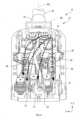
手術器具1には、図1に示すように、ハウジング10と、シャフト40と、が設けられている。更に手術器具1には、エンドエフェクタ50が設けられている。As shown in Figure 1, the
以降において、次に説明するX方向、Y方向およびZ方向を用いて説明する。X方向およびY方向は、図1における紙面に沿って延びるシャフト40の中心軸線40Lと直交する面に沿って延びる方向であって、互いに直交する方向である。シャフト40の中心軸線40Lと直交する面は、図1における紙面と直交する。In the following, the following X, Y, and Z directions will be used for explanation. The X and Y directions are directions that extend along a plane perpendicular to the
X方向は、言い換えると、ハウジング10のベース21における取付面22に沿って延びる方向であり、X方向の正方向は、図1における紙面に対して手前に向かう方向である。Y方向の正方向は、言い換えると、ハウジング10のベース21からカバー11に向かう方向である。Z方向は中心軸線40Lと平行な方向であり、Z方向の正方向は、ハウジング10からエンドエフェクタ50に向かう方向である。The X direction is, in other words, the direction extending along the mounting
ハウジング10は内部空間を有する容器であり、手術器具1のうち、手術ロボットに装着される部分である。ハウジング10は、図2に示すように、カバー11と、ベース21と、を有する。The
カバー11は、ベース21とともにハウジング10の外形を形成し、ハウジング10の内部空間を形成する部材である。カバー11は、図2,3に示すように、上面12と、前面13と、側面14,14と、後面15とを有する。The
上面12は、Z-X平面に沿って延びる面であり、カバー11におけるY方向の正側に位置する面である。前面13は、X-Y平面に沿って延びる面であり、カバー11におけるZ方向の正側に位置する面である。側面14,14は、Y-Z平面に沿って延びる面であり、カバー11におけるX方向の正側および負側に位置する面である。後面15は、X-Y平面に沿って延びる面であり、カバー11におけるZ方向の負側に位置する面である。The
なお、上面12、前面13、側面14,14および後面15は、平面のみから構成される面であってもよいし、平面および曲面を組み合わせた面であってもよいし、曲面のみから構成される面であってもよい。また、上面12、前面13、側面14,14および後面15には、それらの面から突出する構成や、凹む構成が設けられてもよい。The
図2に示されているように、カバー11には、フラッシュポート16が設けられている。具体的には、カバー11の上面12にフラッシュポート16が設けられている。なお、フラッシュポート16は、カバー11の前面13に設けられてもよいし、側面14,14に設けられてもよい。As shown in Figure 2, the
フラッシュポート16は、カバー11におけるベース21との間に中心軸線40Lを挟む位置に配置されている。具体的には、後述するベース21の開口部27との間に中心軸線40Lを挟む位置に配置されている。The
フラッシュポート16はカバー11を貫通する貫通孔であって、ハウジング10の外部からその内部空間へ洗浄液を供給する際に用いられる貫通孔である。フラッシュポート16は、カバー11の上面12を貫通する。The
Z方向において、フラッシュポート16はカバー11の中央よりも正側に配置されている。言い換えると、カバー11における領域のうち、そのカバー11の中央よりもシャフト40に近い領域に配置されている。具体的には、フラッシュポート16は上面12において、Z方向における中央よりもシャフト40に近い領域に配置されている。In the Z direction, the
Y方向から見て、フラッシュポート16は、フラッシュポート16の軸線16Lが中心軸線40Lとは異なる位置を通って延びるように配置されている。言い換えるとフラッシュポート16は、中心軸線40Lが延びる位置とは異なる位置に配置されている。When viewed from the Y direction, the
具体的には、Y方向から見て、フラッシュポート16が中心軸線40LよりもX方向の負側に離れた位置に配置されている。なお、フラッシュポート16は、中心軸線40LよりもX方向の正側に離れた位置に配置されてもよい。Specifically, when viewed from the Y direction, the
軸線16Lは、貫通孔であるフラッシュポート16の中心を通る軸線である。貫通孔が円筒形状または円柱形状を有する場合には、円筒形状または円柱形状の中心軸線が軸線16Lである。
ベース21は、図4に示すように、カバー11とともにハウジング10の外形を形成する板状に形成された部材であり、手術器具1のうち手術ロボットに装着される部分である。ベース21におけるY方向の正側にはカバー11が配置される。ベース21におけるY方向の負側の面は取付面22である。取付面22は、手術ロボットに手術器具1を装着するための面であり、手術ロボットと接触する面である。図4において、手術ロボットは図示されていない。As shown in Figure 4, the
ベース21におけるZ方向の正側端部には、例えば図1,5等に示すように、シャフト40が取り付けられるシャフト取付部23が設けられている。シャフト取付部23は、ベース21におけるカバー11側(言い換えると、Y方向の正側)に突出した部分に設けられている。シャフト取付部23は、ベース21におけるX方向の中央に設けられている。シャフト取付部23はZ方向の正側に突出する円筒状の形状を有する。シャフト40は、シャフト取付部23の内部に差し込まれて保持される。At the positive end of the base 21 in the Z direction, a
ベース21におけるZ方向の負側端部には、メインフラッシュポート25が設けられている。メインフラッシュポート25は、ハウジング10の外部からシャフト40の内部へ洗浄液を供給する際に用いられる貫通孔である。A main
メインフラッシュポート25は、ベース21のシャフト40とは反対側において、カバー11側(言い換えると、Y方向の正側)に延びた部分に設けられている。メインフラッシュポート25は、Z方向に延びる貫通孔である。メインフラッシュポート25は、シャフト40の中心軸線40Lから外れた位置に配置されてもよいし、中心軸線40L上の位置に配置されてもよい。The main
メインフラッシュポート25にはチューブ26(図5参照)が接続されている。チューブ26は、メインフラッシュポート25とともにシャフト40の内部へ洗浄液を供給する際に用いられる部材である。A tube 26 (see Figure 5) is connected to the main
チューブ26は筒状に形成された部材であり、樹脂などの柔軟性を有する材料を用いて形成された部材である。チューブ26はZ方向に沿って配置されている。チューブ26は直線状に配置されてもよいし、直線および曲線を組わせた形状に配置されてもよいし、曲線状に配置されてもよい。
チューブ26は、フラッシュポート16とベース21との間に配置されている。具体的には、フラッシュポート16と後述するベース21の開口部27との間に配置されている。The
Y方向から見て、チューブ26は、フラッシュポート16の軸線16Lが中心軸線40Lとは異なる位置を通って延びるように配置されている。具体的には、Y方向から見て、チューブ26は、フラッシュポート16よりもX方向の正側に離れた位置に配置されている。なお、チューブ26は、フラッシュポート16よりもX方向の負側に離れた位置に配置されていてもよい。When viewed from the Y direction, the
チューブ26のZ方向の負側端部は、メインフラッシュポート25に接続されている。チューブ26のZ方向の正側端部は、シャフト40の内部に配置されている。The negative end of the
ベース21には、図4に示すように、3つの開口部27,27,27と、3つのスライダ28,28,28とが設けられている。以降において、1つの開口部27について説明する場合があるが、他の2つの開口部27,27も同様の構成を有する。以降において、開口部27は従動溝とも表記する。また、以降において、1つのスライダ28について説明する場合があるが、他の2つのスライダ28,28も同様の構成を有する。As shown in Figure 4, the
開口部27は、ハウジング10の内部空間と外部とをつなぐ貫通孔である。開口部27はベース21に設けられた貫通孔であって、Z方向に延びる長孔である。3つの開口部27,27,27はX方向に等間隔に並んで配置されている。The
Z方向において、3つの開口部27,27,27はベース21の中央領域に配置されている。フラッシュポート16は、3つの開口部27,27,27よりもZ方向の正側に配置されている。言い換えると、3つの開口部27,27,27よりもシャフト40に近い領域に配置されている。In the Z direction, the three
開口部27の数は、エンドエフェクタ50における関節部および/または鉗子などの動きなどに基づいて定めることができる。言い換えると、開口部27の数は、手術器具1に求められる仕様に基づく動きに基づいて定めることができる。開口部27の数は、求められる仕様に応じて3つよりも多くてもよいし、少なくてもよい。The number of
スライダ28は、手術ロボットから駆動力が伝達され、エンドエフェクタ50に駆動力を伝達する構成を有している。また、スライダ28は、手術ロボットと着脱が可能な構成を有している。The
スライダ28は、ベース21に対して相対移動可能に配置されている。具体的には、スライダ28は、ベース21に対して相対的に直線方向へ移動可能に配置されている。なお、スライダ28は、ベース21に対して相対的に回転可能に配置されてもよい。The
3つの開口部27,27,27のそれぞれに、1つのスライダ28が配置され、1つのスライダ28は、1つの開口部27の内部をZ方向に移動可能に配置されている。言い換えるとスライダ28は、ベース21に対して相対的に直線方向に移動可能に配置されている。1つのスライダ28が、全ての開口部27,27,27のそれぞれに配置されてもよいし、一部の開口部27にのみ配置されてもよい。One
ベース21には、図5に示すように、3つのワイヤ29,29,29が設けられている。ワイヤ29は、スライダ28に伝達された駆動力をエンドエフェクタ50に伝達する構成を有している。1つのスライダ28には、1本または2本のワイヤ29が配置されている。以降において、1つのワイヤ29について説明する場合があるが、他の2つのワイヤ29,29についても同様の構成を有する。As shown in Fig. 5, three
ワイヤ29は、導電性を有する材料を用いて長尺状に形成されたワイヤである。ワイヤ29は、例えば、ステンレス鋼、タングステン、タングステンを成分に含む合金、またはピアノ線(例えば、JIS G 3522に規定されるもの。)などの、手術用ロボットシステムのマニピュレータで使用される金属材料を用いて形成されていてもよい。The
シャフト40は、図1に示すように、ハウジング10のベース21からZ方向に延びる円筒形状に形成された部材である。シャフト40は円筒形状以外の筒形状を有してもよい。As shown in Figure 1, the
シャフト40におけるZ方向の正側端部にはエンドエフェクタ50が配置されている。シャフト40におけるZ方向の負側端部は、図5に示すように、ベース21のシャフト取付部23に取り付けられている。筒状のシャフト40は、その内側の内部空間がハウジング10の内部空間と連通している。An
シャフト40の内部には、図6に示すように、チューブ26と、複数のワイヤ29と、電気配線51と、が配置されている。電気配線51は、エンドエフェクタ50への電流の供給に用いられる。As shown in Figure 6, the
チューブ26は、シャフト40の内部における中心近傍に配置されている。複数のワイヤ29および電気配線51は、チューブ26の周囲に配置されている。具体的には、チューブ26の周囲に6本のワイヤ29と、1本の電気配線51が配置されている。The
図1に示すエンドエフェクタ50は、手術に使用される器具である。エンドエフェクタ50は、モノポーラの電気メスおよび鉗子の機能を有する。エンドエフェクタ50は、電気メスおよび鉗子の一方のみの機能を有してもよいし、その他の機能を有してもよい。The
エンドエフェクタ50には、図6に示すように、シャフト40の内部を通って配置された6本のワイヤ29および電気配線51が接続されている。エンドエフェクタ50は、6本のワイヤ29により鉗子が開閉され、および、鉗子の向きが変更される構成を有する。エンドエフェクタ50は、電気配線51により供給される高周波電流を鉗子に伝達する構成を有する。As shown in Fig. 6, six
次に、上記構成の手術器具1の洗浄時における洗浄液の流れについて図7および図8を参照しながら説明する。まず、フラッシュポート16から供給される洗浄液の流れについて説明する。Next, the flow of the cleaning fluid when cleaning the
フラッシュポート16から供給される洗浄液は、図7に示すように、外部からハウジング10の内部空間に流入する。この時、洗浄液はY方向の正側から負側に向かって流れる。洗浄液は、ハウジング10の内部空間を広がって流れる。洗浄液は、ハウジング10の内部空間に存在する汚れなどを取り除く、言い換えるとハウジング10の内部空間に存在する汚れなどを洗浄する。As shown in Figure 7, the cleaning liquid supplied from the
ハウジング10の内部空間に流入した洗浄液は、ハウジング10の内部において、そのハウジング10の外部と連通する箇所に向かって流れる。具体的には、複数の開口部27,27,27や、カバー11とベース21とのつなぎ目などに向かって流れる。The cleaning liquid that flows into the internal space of the
複数の開口部27,27,27と、カバー11とベース21とのつなぎ目と、を比較すると、洗浄液の流れやすさが異なる。つまり、複数の開口部27,27,27からハウジング10の外部への流出のしやすさと、上述のつなぎ目からハウジング10の外部への流出のしやすさと、が異なる。The ease with which cleaning liquid flows is different when comparing the
複数の開口部27,27,27における洗浄液が流れる部分の流路抵抗は、つなぎ目における流路抵抗よりも小さい。そのため、洗浄液は、ハウジング10の内部空間に広がった後、複数の開口部27,27,27に向かって流れやすく、それ以外の方向へは流れにくい。The flow resistance of the portion of the
ハウジング10の内部空間に流入した洗浄液は、図7および図8に示すように、フラッシュポート16からY方向の負側に向かって流れるとともに、Z方向の負側に向かって流れやすい。言い換えると、ハウジング10の内部空間に流入した洗浄液は、Z方向の正側に向かって流れにくい。7 and 8, the cleaning liquid that has flowed into the internal space of the
Z方向において、フラッシュポート16を基準にして正側に、シャフト40が配置されている。そのため、ハウジング10の内部空間に流入した洗浄液は、シャフト40に向かって流れにくく、このためシャフト40の内部に流入しにくい。In the Z direction, the
ハウジング10の内部空間に流入した洗浄液の一部は、X方向の正側に向かっても流れやすい。シャフト40はZ方向に延びて配置されていて、X方向の正側に向かう流れは、シャフト40を横切る方向の流れであり、シャフト40の内部に向かう流れではない。そのため、ハウジング10の内部空間に流入した洗浄液は、シャフト40の内部に向かって流れにくく、このためシャフト40の内部に流入しにくい。Some of the cleaning liquid that has flowed into the internal space of the
また、洗浄液はフラッシュポート16から、他の部品に衝突せずにチューブ26に衝突することなく、ハウジング10の内部空間に流入する。以降において、洗浄液が他の部品に衝突せずにチューブに衝突することを「直接衝突」とも記載する。そのため、洗浄液の流れの方向が、チューブ26に直接衝突することによって、シャフト40の内部に向かう方向へ変更されることが発生しにくい。In addition, the cleaning fluid flows from the
次に、メインフラッシュポート25から供給される洗浄液の流れについて説明する。図7および図8に示すように、メインフラッシュポート25から供給される洗浄液は、チューブ26に流入する。洗浄液は、チューブ26によってシャフト40の内部に導かれる。Next, the flow of the cleaning fluid supplied from the main
チューブ26によって導かれた洗浄液は、図9に示すように、シャフト40の内部へ流出する。シャフト40のZ方向の正側の端部は閉塞されており、Z方向の正の方向に向かってチューブ26から流出した洗浄液は、シャフト40の内部で流れの向きをZ方向の負の方向に変える。The cleaning liquid guided by the
流れの向きを変えた洗浄液は、シャフト40の内部に存在する汚れなどを取り除く。言い換えると、シャフト40の内部を洗浄する。ハウジング10の内部空間まで戻った洗浄液は、複数の開口部27,27,27などからハウジング10の外部へ流出する。The redirected cleaning fluid removes dirt and other contaminants from inside the
なお、図10に示すように、シャフト40に洗浄液を外部に排出する排出孔55が設けられてもよい。図10では、シャフト40におけるエンドエフェクタ50が取り付けられる箇所に排出孔55が設けられている。排出孔55が設けられる場所は、エンドエフェクタ50が取り付けられる箇所以外の場所であってもよい。As shown in Fig. 10, the
上記の構成の手術器具1によれば、フラッシュポート16からハウジング10の内部空間に流入した洗浄液は、シャフト40の中心軸線40Lを横切り、複数の開口部27,27,27からハウジング10の外部へ流出しやすい。言い換えると、洗浄液における主な流れの方向は、複数の開口部27,27,27に向かう方向となりやすい。洗浄液の流れる方向は、シャフト40の中心軸線40Lを横切る方向となりやすい。According to the
洗浄液の流れ方向の成分うち、シャフト40の内部に向かう流れの成分は、複数の開口部27,27,27に向かう流れの成分よりも小さくなりやすい。つまり、洗浄液の流れ方向は、ハウジング10の内部空間からシャフト40の内部に向かいにくくなる。Of the flow direction components of the cleaning liquid, the flow component toward the inside of the
また、フラッシュポート16からハウジング10の内部に供給された洗浄液は、ハウジング10の中央に向かいやすい。言い換えると、フラッシュポート16から複数の開口部27,27,27に向かう洗浄液の流れ方向の成分のうち、Z軸の負方向の成分が増えやすい。例えば、洗浄液は、シャフト40から離れる方向に向かって流れやすく、このため、洗浄液はハウジング10の内部空間からシャフト40の内部に流入しにくくなる。In addition, the cleaning liquid supplied from the
フラッシュポート16の軸線16Lが、シャフト40の中心軸線40Lとは異なる位置を通って延びるため、フラッシュポート16から軸線16Lに沿って流入する洗浄液の流れの主な方向は、シャフト40の内部に向かう方向とは異なる方向となりやすい。このため、洗浄液は、ハウジング10の内部空間からシャフト40の内部に流入しにくくなる。Because the
そのため、ハウジング10の内部空間を洗浄した後の洗浄液であって、シャフト40の内部に流入した洗浄液を、シャフト40の内部からハウジング10の内部空間に戻してハウジング10の外部へ流出させる必要性が低下する。その結果、手術器具1の洗浄に要する時間が長くなりにくく、洗浄効率の悪化を抑制しやすい。Therefore, there is less need to return the cleaning liquid that has flowed into the inside of the
Claims (2)
Translated fromJapanese前記ハウジングは、洗浄液が外部から流入する第1の貫通孔であるフラッシュポートと、前記洗浄液が外部へ流出する少なくとも1つの開口部と、前記シャフトの内部に供給される洗浄液が流入する第2の貫通孔であるメインフラッシュポートと、前記内部空間に配置され、前記メインフラッシュポートから流入した洗浄液を前記シャフトの内部に供給するチューブと、
を有し、
前記フラッシュポートは、前記少なくとも1つの開口部との間に前記シャフトの中心軸線を挟む位置に配置されるとともに、前記フラッシュポートの軸線が前記中心軸線とは異なる位置を通って延びるように配置されており、
前記フラッシュポートは、前記ハウジングにおいて、前記少なくとも1つの開口部よりも前記シャフトに近い領域であって、前記中心軸線から前記中心軸線と交わる方向の一方の側に離れた位置に備えられ、
前記少なくとも1つの開口部は、前記ハウジングにおいて、前記中心軸線から前記一方の側とは反対の側に離れた位置に備えられており、
前記チューブの一方の端部は、前記メインフラッシュポートに接続され、前記チューブの他方の端部は、前記シャフトの内部に配置されている、
手術器具。 A surgical instrument having a housing having an internal space and a shaft formed in a cylindrical shape extending from the housing and communicating with the internal space,
the housing includes a flush port which isa first through hole through which a cleaning liquid flows in from the outside, at least one opening through which the cleaning liquid flows out to the outside,a main flush port which is a second through hole through which the cleaning liquid supplied to the inside of the shaft flows in, and a tube which is disposed in the internal space and supplies the cleaning liquid flowing in from the main flush port to the inside of the shaft;
having
The flush port is disposed at a position sandwiching a central axis of the shaft between the flush port and the at least one opening, and the axis of the flush port is disposed so as to extend through a position different from the central axis,
The flush port is provided in the housing in a region closer to the shaft than the at least one opening, and at a position away from the central axis on one side in a direction intersecting with the central axis,
the at least one opening is provided in the housing at a position away from the central axis on a side opposite to the one side,
One end of the tube is connected to the main flush port, and the other end of the tube is disposed inside the shaft.
Surgical instruments.
Applications Claiming Priority (1)
| Application Number | Priority Date | Filing Date | Title |
|---|---|---|---|
| PCT/JP2022/020810WO2023223495A1 (en) | 2022-05-19 | 2022-05-19 | Surgical instrument |
Publications (2)
| Publication Number | Publication Date |
|---|---|
| JPWO2023223495A1 JPWO2023223495A1 (en) | 2023-11-23 |
| JP7513341B2true JP7513341B2 (en) | 2024-07-09 |
Family
ID=88835073
Family Applications (1)
| Application Number | Title | Priority Date | Filing Date |
|---|---|---|---|
| JP2024517018AActiveJP7513341B2 (en) | 2022-05-19 | 2022-05-19 | Surgical instruments |
Country Status (5)
| Country | Link |
|---|---|
| US (1) | US20250057586A1 (en) |
| EP (1) | EP4501268A4 (en) |
| JP (1) | JP7513341B2 (en) |
| CN (1) | CN119212642A (en) |
| WO (1) | WO2023223495A1 (en) |
Citations (4)
| Publication number | Priority date | Publication date | Assignee | Title |
|---|---|---|---|---|
| JP2009028156A (en) | 2007-07-25 | 2009-02-12 | Terumo Corp | Medical manipulator and its washing method |
| JP2010207260A (en) | 2009-03-06 | 2010-09-24 | Top Corp | Forceps |
| US20130345701A1 (en) | 2012-06-26 | 2013-12-26 | Covidien Lp | Surgical instruments with structures to provide access for cleaning |
| US20170128697A1 (en) | 2015-11-06 | 2017-05-11 | Kardium Inc. | Medical device systems and methods including safety release, lumen fluid-providing mechanisms, or both |
Family Cites Families (8)
| Publication number | Priority date | Publication date | Assignee | Title |
|---|---|---|---|---|
| US8273097B2 (en)* | 2010-04-30 | 2012-09-25 | Medtronic Xomed, Inc. | Powered surgical tissue cutting instrument having an irrigation system |
| WO2015023772A1 (en)* | 2013-08-15 | 2015-02-19 | Intuitive Surgical Operations, Inc. | Surgical instruments and methods of cleaning surgical instruments |
| CN109414300B (en)* | 2016-07-14 | 2021-11-09 | 直观外科手术操作公司 | Instrument flushing system |
| US12133775B2 (en)* | 2019-07-09 | 2024-11-05 | Cilag Gmbh International | Adapter for a robotic surgical tool cleaning system |
| US11957523B2 (en)* | 2020-05-29 | 2024-04-16 | Medicaroid Corporation | Surgical instrument |
| JP7477368B2 (en)* | 2020-05-29 | 2024-05-01 | 株式会社メディカロイド | Surgical instruments |
| CN214805336U (en)* | 2020-12-28 | 2021-11-23 | 深圳市精锋医疗科技有限公司 | Surgical instrument, slave operation device, and surgical robot |
| CN120585474A (en)* | 2020-12-28 | 2025-09-05 | 深圳市精锋医疗科技股份有限公司 | Surgical instruments, operating equipment and surgical robots |
- 2022
- 2022-05-19JPJP2024517018Apatent/JP7513341B2/enactiveActive
- 2022-05-19CNCN202280096101.6Apatent/CN119212642A/enactivePending
- 2022-05-19WOPCT/JP2022/020810patent/WO2023223495A1/ennot_activeCeased
- 2022-05-19EPEP22942700.0Apatent/EP4501268A4/enactivePending
- 2024
- 2024-11-04USUS18/936,272patent/US20250057586A1/enactivePending
Patent Citations (4)
| Publication number | Priority date | Publication date | Assignee | Title |
|---|---|---|---|---|
| JP2009028156A (en) | 2007-07-25 | 2009-02-12 | Terumo Corp | Medical manipulator and its washing method |
| JP2010207260A (en) | 2009-03-06 | 2010-09-24 | Top Corp | Forceps |
| US20130345701A1 (en) | 2012-06-26 | 2013-12-26 | Covidien Lp | Surgical instruments with structures to provide access for cleaning |
| US20170128697A1 (en) | 2015-11-06 | 2017-05-11 | Kardium Inc. | Medical device systems and methods including safety release, lumen fluid-providing mechanisms, or both |
Also Published As
| Publication number | Publication date |
|---|---|
| JPWO2023223495A1 (en) | 2023-11-23 |
| EP4501268A1 (en) | 2025-02-05 |
| WO2023223495A1 (en) | 2023-11-23 |
| CN119212642A (en) | 2024-12-27 |
| EP4501268A4 (en) | 2025-05-14 |
| US20250057586A1 (en) | 2025-02-20 |
Similar Documents
| Publication | Publication Date | Title |
|---|---|---|
| KR102822249B1 (en) | Ultrasonic surgical handpiece assembly | |
| US8562604B2 (en) | Bipolar high frequency treatment device | |
| CN106923902B (en) | Operating robot snakelike joint, surgical instrument and endoscope | |
| JP4980653B2 (en) | Ultrasound probe with ultrasound probe and ultrasound probe | |
| WO2015137139A1 (en) | Clamping unit and bipolar treatment tool | |
| EP3005966A1 (en) | Grasping treatment device | |
| EP3829412A1 (en) | A joint | |
| JP7513341B2 (en) | Surgical instruments | |
| CN114869449A (en) | Resectoscope, electrode tool for resectoscope, and guide for electrode tool | |
| US12268434B2 (en) | Electrode instrument for a resectoscope, and resectoscope | |
| JP7567019B2 (en) | catheter | |
| CN117858737A (en) | Steerable instrument for endoscopic or invasive applications | |
| JP4969289B2 (en) | Tip deflectable catheter | |
| CN113543941B (en) | Surgical tools for surgical assistance robots | |
| JP4551673B2 (en) | Ion exchange resin molded product and actuator element using the same | |
| JP6850056B1 (en) | Surgical tool | |
| JPWO2019106916A1 (en) | Insertion device, connection structure of exterior members, endoscope | |
| US20250114827A1 (en) | Cleaning tool for surgical instrument | |
| EP3884896A1 (en) | Electrosurgical forceps for grasping, treating, and/or dividing tissue | |
| US20210338311A1 (en) | Electrosurgical forceps for grasping, treating, and/or dividing tissue | |
| JP4336943B2 (en) | Endoscope operation section | |
| JP2009195379A (en) | Catheter | |
| WO2004079887A1 (en) | Ion exchange resin molded article | |
| JPS6397153A (en) | Treatment tool for endoscope | |
| JPH08257974A (en) | Manipulator |
Legal Events
| Date | Code | Title | Description |
|---|---|---|---|
| A621 | Written request for application examination | Free format text:JAPANESE INTERMEDIATE CODE: A621 Effective date:20240315 | |
| A871 | Explanation of circumstances concerning accelerated examination | Free format text:JAPANESE INTERMEDIATE CODE: A871 Effective date:20240315 | |
| A131 | Notification of reasons for refusal | Free format text:JAPANESE INTERMEDIATE CODE: A131 Effective date:20240409 | |
| A521 | Request for written amendment filed | Free format text:JAPANESE INTERMEDIATE CODE: A523 Effective date:20240502 | |
| TRDD | Decision of grant or rejection written | ||
| A01 | Written decision to grant a patent or to grant a registration (utility model) | Free format text:JAPANESE INTERMEDIATE CODE: A01 Effective date:20240611 | |
| A61 | First payment of annual fees (during grant procedure) | Free format text:JAPANESE INTERMEDIATE CODE: A61 Effective date:20240620 | |
| R150 | Certificate of patent or registration of utility model | Ref document number:7513341 Country of ref document:JP Free format text:JAPANESE INTERMEDIATE CODE: R150 |