JP7511680B2 - Processing supplemental enhancement information in the subpicture sub-bitstream extraction process - Patents.com - Google Patents
Processing supplemental enhancement information in the subpicture sub-bitstream extraction process - Patents.comDownload PDFInfo
- Publication number
- JP7511680B2 JP7511680B2JP2022575700AJP2022575700AJP7511680B2JP 7511680 B2JP7511680 B2JP 7511680B2JP 2022575700 AJP2022575700 AJP 2022575700AJP 2022575700 AJP2022575700 AJP 2022575700AJP 7511680 B2JP7511680 B2JP 7511680B2
- Authority
- JP
- Japan
- Prior art keywords
- bitstream
- video
- sub
- picture
- sps
- Prior art date
- Legal status (The legal status is an assumption and is not a legal conclusion. Google has not performed a legal analysis and makes no representation as to the accuracy of the status listed.)
- Active
Links
Images


Classifications
- H—ELECTRICITY
- H04—ELECTRIC COMMUNICATION TECHNIQUE
- H04N—PICTORIAL COMMUNICATION, e.g. TELEVISION
- H04N19/00—Methods or arrangements for coding, decoding, compressing or decompressing digital video signals
- H04N19/10—Methods or arrangements for coding, decoding, compressing or decompressing digital video signals using adaptive coding
- H04N19/169—Methods or arrangements for coding, decoding, compressing or decompressing digital video signals using adaptive coding characterised by the coding unit, i.e. the structural portion or semantic portion of the video signal being the object or the subject of the adaptive coding
- H04N19/17—Methods or arrangements for coding, decoding, compressing or decompressing digital video signals using adaptive coding characterised by the coding unit, i.e. the structural portion or semantic portion of the video signal being the object or the subject of the adaptive coding the unit being an image region, e.g. an object
- H04N19/172—Methods or arrangements for coding, decoding, compressing or decompressing digital video signals using adaptive coding characterised by the coding unit, i.e. the structural portion or semantic portion of the video signal being the object or the subject of the adaptive coding the unit being an image region, e.g. an object the region being a picture, frame or field
- H—ELECTRICITY
- H04—ELECTRIC COMMUNICATION TECHNIQUE
- H04N—PICTORIAL COMMUNICATION, e.g. TELEVISION
- H04N19/00—Methods or arrangements for coding, decoding, compressing or decompressing digital video signals
- H04N19/10—Methods or arrangements for coding, decoding, compressing or decompressing digital video signals using adaptive coding
- H04N19/169—Methods or arrangements for coding, decoding, compressing or decompressing digital video signals using adaptive coding characterised by the coding unit, i.e. the structural portion or semantic portion of the video signal being the object or the subject of the adaptive coding
- H04N19/182—Methods or arrangements for coding, decoding, compressing or decompressing digital video signals using adaptive coding characterised by the coding unit, i.e. the structural portion or semantic portion of the video signal being the object or the subject of the adaptive coding the unit being a pixel
- H—ELECTRICITY
- H04—ELECTRIC COMMUNICATION TECHNIQUE
- H04N—PICTORIAL COMMUNICATION, e.g. TELEVISION
- H04N19/00—Methods or arrangements for coding, decoding, compressing or decompressing digital video signals
- H04N19/10—Methods or arrangements for coding, decoding, compressing or decompressing digital video signals using adaptive coding
- H04N19/169—Methods or arrangements for coding, decoding, compressing or decompressing digital video signals using adaptive coding characterised by the coding unit, i.e. the structural portion or semantic portion of the video signal being the object or the subject of the adaptive coding
- H04N19/184—Methods or arrangements for coding, decoding, compressing or decompressing digital video signals using adaptive coding characterised by the coding unit, i.e. the structural portion or semantic portion of the video signal being the object or the subject of the adaptive coding the unit being bits, e.g. of the compressed video stream
- H—ELECTRICITY
- H04—ELECTRIC COMMUNICATION TECHNIQUE
- H04N—PICTORIAL COMMUNICATION, e.g. TELEVISION
- H04N19/00—Methods or arrangements for coding, decoding, compressing or decompressing digital video signals
- H04N19/10—Methods or arrangements for coding, decoding, compressing or decompressing digital video signals using adaptive coding
- H04N19/169—Methods or arrangements for coding, decoding, compressing or decompressing digital video signals using adaptive coding characterised by the coding unit, i.e. the structural portion or semantic portion of the video signal being the object or the subject of the adaptive coding
- H04N19/188—Methods or arrangements for coding, decoding, compressing or decompressing digital video signals using adaptive coding characterised by the coding unit, i.e. the structural portion or semantic portion of the video signal being the object or the subject of the adaptive coding the unit being a video data packet, e.g. a network abstraction layer [NAL] unit
- H—ELECTRICITY
- H04—ELECTRIC COMMUNICATION TECHNIQUE
- H04N—PICTORIAL COMMUNICATION, e.g. TELEVISION
- H04N19/00—Methods or arrangements for coding, decoding, compressing or decompressing digital video signals
- H04N19/30—Methods or arrangements for coding, decoding, compressing or decompressing digital video signals using hierarchical techniques, e.g. scalability
- H—ELECTRICITY
- H04—ELECTRIC COMMUNICATION TECHNIQUE
- H04N—PICTORIAL COMMUNICATION, e.g. TELEVISION
- H04N19/00—Methods or arrangements for coding, decoding, compressing or decompressing digital video signals
- H04N19/50—Methods or arrangements for coding, decoding, compressing or decompressing digital video signals using predictive coding
- H04N19/597—Methods or arrangements for coding, decoding, compressing or decompressing digital video signals using predictive coding specially adapted for multi-view video sequence encoding
- H—ELECTRICITY
- H04—ELECTRIC COMMUNICATION TECHNIQUE
- H04N—PICTORIAL COMMUNICATION, e.g. TELEVISION
- H04N19/00—Methods or arrangements for coding, decoding, compressing or decompressing digital video signals
- H04N19/70—Methods or arrangements for coding, decoding, compressing or decompressing digital video signals characterised by syntax aspects related to video coding, e.g. related to compression standards
Landscapes
- Engineering & Computer Science (AREA)
- Multimedia (AREA)
- Signal Processing (AREA)
- Compression Or Coding Systems Of Tv Signals (AREA)
- Image Processing (AREA)
Description
Translated fromJapanese [関連出願への相互参照]
本出願は、2020年6月9日に出願された米国仮特許出願No.63/036,908の優先権及び利益を主張した、2021年6月8日に出願された国際特許出願第PCT/US2021/036369号に基づくものである。全ての上記の特許出願の全開示を参照することにより援用する。 CROSS-REFERENCE TO RELATED APPLICATIONS
This application is based on International Patent Application No. PCT/US2021/036369, filed June 8, 2021, which claims priority to and the benefit of U.S. Provisional Patent Application No. 63/036,908, filed June 9,2020.The entire disclosures of all of the above patent applications are incorporated by reference.
[技術分野]
本特許文献は、画像及びビデオデータ処理に関する。 [Technical field]
This patent document relates to image and video data processing.
デジタルビデオは、インターネット及び他のデジタル通信ネットワークにおける最大の帯域幅使用を占めている。ビデオを受信及び表示できる接続ユーザデバイスの数が増加するにつれて、デジタルビデオの利用に対する帯域幅需要が増加し続けることが想定される。Digital video accounts for the largest bandwidth usage on the Internet and other digital communications networks. As the number of connected user devices capable of receiving and displaying video increases, the bandwidth demands for digital video usage are expected to continue to increase.
本文献は、ビデオ又は画像のコーディング表現を処理するためにビデオエンコーダ及びデコーダによって使用できる技術を開示する。This document discloses techniques that can be used by video encoders and decoders to process coded representations of videos or images.
1つの例示的な態様では、ビデオデータを処理する方法が開示される。当該方法は、ビデオとビデオのビットストリームとの間の変換を実行するステップを含み、ビットストリームは、ルールに従って1つ以上のサブピクチャを含む複数のレイヤを含み、ルールは、出力ビットストリームがビットストリームから抽出されるサブピクチャサブビットストリーム抽出プロセス中に、出力ビットストリームに適用可能でないスケーラブルネスト化されたSEIメッセージを含む補足エンハンスメント情報ネットワーク抽象レイヤユニット(SEI NALユニット)が出力ビットストリームにおいて省略されることを指定する。
In one exemplary aspect, a method for processing video data is disclosed, the method including performing a conversion between a video and a video bitstream, the bitstream including a plurality of layers including one or more sub-pictures according to a rule, the rule specifying that during a sub-picture sub-bitstream extraction process in which an output bitstream is extracted from the bitstream, supplemental enhancement information network abstraction layer units (SEI NAL units) including scalablenested SEI messages that are not applicable to the output bitstream are omitted in the output bitstream.
1つの例示的な態様では、ビデオデータを処理する方法が開示される。当該方法は、ビデオとビデオのビットストリームとの間の変換を実行するステップを含み、ビットストリームは、ルールに従って、1つ以上のサブピクチャを含む1つ以上のピクチャを含む複数のレイヤを含み、ルールは、ビットストリームに対するサブピクチャサブビットストリーム抽出プロセスによって抽出されたサブピクチャシーケンスを識別する第1のサブピクチャインデックスがピクチャ当たり複数のサブピクチャを有するビットストリームのレイヤの第2のサブピクチャインデックスに基づくことを指定する。In one exemplary aspect, a method of processing video data is disclosed. The method includes performing a conversion between a video and a bitstream of video, the bitstream including a plurality of layers including one or more pictures including one or more subpictures according to a rule, the rule specifying that a first subpicture index identifying a subpicture sequence extracted by a subpicture subbitstream extraction process for the bitstream is based on a second subpicture index of a layer of the bitstream having a plurality of subpictures per picture.
1つの例示的な態様では、ビデオデータを処理する方法が開示される。当該方法は、ビデオとビデオのビットストリームとの間の変換を実行するステップを含み、ビットストリームは、ルールに従って、1つ以上のサブピクチャを含む1つ以上のピクチャを含む1つ以上のサブレイヤを含む1つ以上のレイヤを含み、ルールは、出力ターゲットサブビットストリームがビットストリームから抽出されるサブピクチャサブビットストリーム抽出プロセス中に、1つ以上のシンタックス構造に対して選択的に実行される書き換え操作を指定し、1つ以上のシンタックスエレメントは、出力ターゲットサブビットストリームの情報を含む。In one exemplary aspect, a method for processing video data is disclosed. The method includes performing a conversion between a video and a bitstream of video, the bitstream including one or more layers including one or more sublayers including one or more pictures including one or more subpictures according to rules, the rules specifying rewriting operations to be selectively performed on one or more syntax structures during a subpicture subbitstream extraction process in which an output target subbitstream is extracted from the bitstream, the one or more syntax elements including information of the output target subbitstream.
1つの例示的な態様では、ビデオデータを処理する方法が開示される。当該方法は、ビデオとビデオのビットストリームとの間の変換を実行するステップを含み、ビットストリームは、ルールに従って、1つ以上のサブピクチャを含む1つ以上のピクチャを含む1つ以上のレイヤを含み、ルールは、条件に応じて、サブピクチャサブビットストリーム抽出プロセス中に抽出されるターゲット出力サブピクチャサブビットストリームの第1の補足エンハンスメント情報ネットワーク抽象レイヤ(SEI NAL)ユニットの選択処理を指定する。In one exemplary aspect, a method for processing video data is disclosed. The method includes performing a conversion between a video and a video bitstream, the bitstream including one or more layers including one or more pictures including one or more subpictures according to a rule, the rule specifying a selection process of a first supplemental enhancement information network abstraction layer (SEI NAL) unit of a target output subpicture subbitstream to be extracted during a subpicture subbitstream extraction process according to a condition.
更に他の例示的な態様では、ビデオエンコーダ装置が開示される。ビデオエンコーダは、上述の方法を実現するように構成されたプロセッサを含む。In yet another exemplary aspect, a video encoder apparatus is disclosed. The video encoder includes a processor configured to implement the above-described method.
更に他の例示的な態様では、ビデオデコーダ装置が開示される。ビデオデコーダは、上述の方法を実現するように構成されたプロセッサを含む。In yet another exemplary aspect, a video decoder device is disclosed. The video decoder includes a processor configured to implement the above-described method.
更に他の例示的な態様では、コードを記憶したコンピュータ読み取り可能媒体が開示される。コードは、プロセッサ実行可能コードの形式で本明細書に記載の方法の1つを具現する。In yet another exemplary aspect, a computer readable medium is disclosed having code stored thereon. The code, in the form of processor executable code, embodies one of the methods described herein.
これら及び他の特徴について、本文献を通じて説明する。These and other features are explained throughout this document.
セクションの見出しは、理解を容易にするために本文献で使用されており、各セクションで開示される技術及び実施形態の適用可能性をそのセクションのみに限定するものではない。さらに、H.266の用語は、いくつかの説明において理解を容易にするためにのみ使用され、開示される技術の範囲を限定するためには使用されるものではない。したがって、本明細書に記載の技術は、他のビデオコーデックプロトコル及び設計にも適用可能である。本文献において、編集の変更は、VVC仕様の現在のドラフトに関して、キャンセルされたテキストを示す取り消し線([[]]を含む)と、追加されたテキストを示す強調表示(太字のイタリック体、下線を含む)とによって、テキストに示される。Section headings are used in this document for ease of understanding and are not intended to limit the applicability of the techniques and embodiments disclosed in each section to only that section. Additionally, H.266 terminology is used in some descriptions for ease of understanding only and is not intended to limit the scope of the disclosed techniques. Thus, the techniques described herein are applicable to other video codec protocols and designs. In this document, editorial changes are indicated in the text with strikethrough (including [[]]) indicating canceled text and highlighting (including bold italics and underlines) indicating added text with respect to the current draft of the VVC specification.
1. 導入
本文献は、ビデオコーディング技術に関する。具体的には、サブピクチャシーケンスについてのレベル情報を指定及びシグナリングすることについてのものである。概念は、単一レイヤビデオコーディング及びマルチレイヤビデオコーディングをサポートするいずれかのビデオコーディング標準又は非標準ビデオコーデック、例えば、開発中のバーサタイルビデオコーディング(VVC, Versatile Video Coding)に適用されてもよい。 1. Introduction This document relates to video coding technology. In particular, it is about specifying and signaling level information for sub-picture sequences. The concepts may be applied to any video coding standard or non-standard video codec that supports single-layer and multi-layer video coding, such as the Versatile Video Coding (VVC) under development.
2. 略語
APS 適応パラメータセット(Adaptation Parameter Set)
AU アクセスユニット(Access Unit)
AUD アクセスユニットデリミタ(Access Unit Delimiter)
AVC アドバンストビデオコーディング(Advanced Video Coding)
CLVS コーディングレイヤビデオシーケンス(Coded Layer Video Sequence)
CPB コーディングピクチャバッファ(Coded Picture Buffer)
CRA クリーンランダムアクセス(Clean Random Access)
CTU コーディングツリーユニット(Coding Tree Unit)
CVS コーディングビデオシーケンス(Coded Video Sequence)
DCI 復号能力情報(Decoding Capability Information)
DPB 復号ピクチャバッファ(Decoded Picture Buffer)
EOB ビットストリーム終了(End Of Bitstream)
EOS シーケンス終了(End Of Sequence)
GDR 漸次復号リフレッシュ(Gradual Decoding Refresh)
HEVC 高効率ビデオコーディング(High Efficiency Video Coding)
HRD 仮想参照デコーダ(Hypothetical Reference Decoder)
IDR 瞬時復号リフレッシュ(Instantaneous Decoding Refresh)
ILP レイヤ間予測(Inter-Layer Prediction)
ILRP レイヤ間参照ピクチャ(Inter-Layer Reference Picture)
JEM 共同探査モデル(Joint Exploration Model)
LTRP 長期参照ピクチャ(Long-Term Reference Picture)
MCTS 動き制約タイルセット(Motion-Constrained Tile Sets)
NAL ネットワーク抽象レイヤ(Network Abstraction Layer)
OLS 出力レイヤセット(Output Layer Set)
PH ピクチャヘッダ(Picture Header)
PPS ピクチャパラメータセット(Picture Parameter Set)
PTL プロファイル、層及びレベル(Profile, Tier and Level)
PU ピクチャユニット(Picture Unit)
RAP ランダムアクセスポイント(Random Access Point)
RBSP 未加工バイトシーケンスペイロード(Raw Byte Sequence Payload)
SEI 補足エンハンスメント情報(Supplemental Enhancement Information)
SLI サブピクチャレベル情報(Subpicture Level Information)
SPS シーケンスパラメータセット(Sequence Parameter Set)
STRP 短期参照ピクチャ(Short-Term Reference Picture)
SVC スケーラブルビデオコーディング(Scalable Video Coding)
VCL ビデオコーディングレイヤ(Video Coding Layer)
VPS ビデオパラメータセット(Video Parameter Set)
VTM VVCテストモデル(VVC Test Model)
VUI ビデオユーザビリティ情報(Video Usability Information)
VVC バーサタイルビデオコーディング(Versatile Video Coding) 2. Abbreviations
APS Adaptation Parameter Set
AU Access Unit
AUD Access Unit Delimiter
AVC Advanced Video Coding
CLVS Coded Layer Video Sequence
CPB Coded Picture Buffer
CRA Clean Random Access
CTU Coding Tree Unit
CVS Coded Video Sequence
DCI Decoding Capability Information
DPB Decoded Picture Buffer
EOB End Of Bitstream
EOS End Of Sequence
GDR Gradual Decoding Refresh
HEVC High Efficiency Video Coding
HRD Hypothetical Reference Decoder
IDR Instantaneous Decoding Refresh
ILP Inter-Layer Prediction
ILRP Inter-Layer Reference Picture
JEM Joint Exploration Model
LTRP Long-Term Reference Picture
MCTS Motion-Constrained Tile Sets
NAL Network Abstraction Layer
OLS Output Layer Set
PH Picture Header
PPS Picture Parameter Set
PTL Profile, Tier and Level
PU Picture Unit
RAP Random Access Point
RBSP Raw Byte Sequence Payload
SEI Supplemental Enhancement Information
SLI Subpicture Level Information
SPS Sequence Parameter Set
STRP Short-Term Reference Picture
SVC Scalable Video Coding
VCL Video Coding Layer
VPS Video Parameter Set
VTM VVC Test Model
VUI Video Usability Information
VVC Versatile Video Coding
3. 最初の議論
ビデオコーディング標準は、主に、周知のITU-T及びISO/IEC標準の開発を通じて進化してきた。ITU-TはH.261及びH.263を作成し、ISO/IECはMPEG-1及びMPEG-4 Visualを作成し、2つの組織は共同でH.262/MPEG-2 Video及びH.264/MPEG-4アドバンストビデオコーディング(AVC, Advanced Video Coding)並びにH.265/HEVC[1]標準を作成した。H.262から、ビデオコーディング標準は、時間予測に加えて変換コーディングが利用されるハイブリッドビデオコーディング構造に基づいている。HEVCを越える将来のビデオコーディング技術を探求するために、2015年に共同ビデオ探査チーム(JVET, Joint Video Exploration Team)がVCEG及びMPEGによって共同で設立された。それ以来、多くの新たな方法がJVETによって採用され、共同探査モデル(JEM, Joint Exploration Model)[2]と名付けられた参照ソフトウェアに入れられた。現在、JVET会議は四半期に1回開催されており、新たなコーディング標準は、HEVCと比較して50%のビットレート低減を目指している。新たなビデオコーディング標準は、2018年4月のJVET会議においてバーサタイルビデオコーディング(VVC, Versatile Video Coding)として正式に命名され、その際にVVCテストモデル(VTM, VVC test model)の最初のバージョンがリリースされた。VVC標準化に寄与する継続的な努力が行われているので、JVET会議毎に新たなコーディング技術がVVC標準に採用されている。その後、VVC作業ドラフト及びテストモデルVTMは、毎回の会議後に更新されている。VVCプロジェクトは現在、2020年7月の会議で技術的完成(FDIS)を目指している。 3. Initial Discussion Video coding standards have evolved primarily through the development of well-known ITU-T and ISO/IEC standards. ITU-T created H.261 and H.263, ISO/IEC created MPEG-1 and MPEG-4 Visual, and the two organizations jointly created the H.262/MPEG-2 Video and H.264/MPEG-4 Advanced Video Coding (AVC) and H.265/HEVC[1] standards. Starting with H.262, video coding standards are based on a hybrid video coding structure in which transform coding is utilized in addition to temporal prediction. In order to explore future video coding technologies beyond HEVC, the Joint Video Exploration Team (JVET) was jointly established by VCEG and MPEG in 2015. Since then, many new methods have been adopted by JVET and put into a reference software named the Joint Exploration Model (JEM)[2]. Currently, JVET meetings are held quarterly, and the new coding standard aims to achieve a 50% bitrate reduction compared to HEVC. The new video coding standard was officially named Versatile Video Coding (VVC) at the April 2018 JVET meeting, when the first version of the VVC test model (VTM) was released. As continuous efforts are being made to contribute to VVC standardization, new coding techniques are adopted into the VVC standard at each JVET meeting. Since then, the VVC working draft and test model VTM are updated after each meeting. The VVC project is currently aiming for technical completion (FDIS) at the July 2020 meeting.
3.1. HEVCにおけるピクチャパーティション化方式
HEVCは、最大転送ユニット(MTU, Maximum Transfer Unit)サイズマッチング、並列処理、及び低減されたエンドツーエンド遅延に適用され得る4つの異なるピクチャパーティション化方式、すなわち、レギュラースライス(regular slice)、従属スライス(dependent slice)、タイル及び波面並列処理(WPP, Wavefront Parallel Processing)を含む。 3.1. Picture Partitioning Scheme in HEVC
HEVC includes four different picture partitioning schemes, namely regular slice, dependent slice, tile and wavefront parallel processing (WPP), which can be applied to Maximum Transfer Unit (MTU) size matching, parallel processing, and reduced end-to-end delay.
レギュラースライスは、H.264/AVCと同様である。各レギュラースライスは、それ自身のNALユニットにカプセル化され、ピクチャ内予測(イントラサンプル予測、動き情報予測、コーディングモード予測)及びスライス境界を横切るエントロピーコーディング依存性は、無効にされる。したがって、レギュラースライスは、(ループフィルタリング動作による相互従属が依然として存在する可能性があっても)同じピクチャ内の他のレギュラースライスから独立して再構成できる。Regular slices are similar to H.264/AVC: each regular slice is encapsulated in its own NAL unit, and intra-picture prediction (intra-sample prediction, motion information prediction, coding mode prediction) and entropy coding dependencies across slice boundaries are disabled. Thus, regular slices can be reconstructed independently from other regular slices in the same picture (although there may still be inter-dependencies due to loop filtering operations).
レギュラースライスは、H.264/AVCにおいても事実上同じ形式で利用可能である並列化に使用できる唯一のツールである。レギュラースライスに基づく並列化は、多くのプロセッサ間又はコア間通信を必要としない(予測的にコーディングされたピクチャを復号するときの動き補償のためのプロセッサ間又はコア間データ共有を除く。これは、典型的には、ピクチャ内予測によるプロセッサ間又はコア間データ共有よりもはるかに重い)。しかし、同じ理由で、レギュラースライスの使用は、スライスヘッダのビットコストのため、且つ、スライス境界を横切る予測の欠如のため、かなりのコーディングオーバーヘッドを引き起こす可能性がある。さらに、レギュラースライスは(以下に言及される他のツールとは対照的に)、レギュラースライスのピクチャ内独立性と、各レギュラースライスがそれ自身のNALユニットにカプセル化されることとのため、MTUサイズ要件に一致するビットストリームパーティション化のための重要なメカニズムとしても機能する。多くの場合、並列化の目標及びMTUサイズマッチングの目標は、ピクチャ内のスライスレイアウトに対して矛盾する要求を突きつける。この状況の実現は、以下に言及される並列化ツールの開発をもたらした。Regular slices are the only tool available for parallelization that is available in virtually the same form in H.264/AVC. Parallelization based on regular slices does not require much inter-processor or inter-core communication (except for inter-processor or inter-core data sharing for motion compensation when decoding predictively coded pictures, which is typically much heavier than inter-processor or inter-core data sharing with intra-picture prediction). However, for the same reasons, the use of regular slices can cause significant coding overhead due to the bit cost of slice headers and due to the lack of prediction across slice boundaries. Furthermore, regular slices (in contrast to the other tools mentioned below) also serve as an important mechanism for bitstream partitioning to match MTU size requirements due to the intra-picture independence of regular slices and the encapsulation of each regular slice in its own NAL unit. In many cases, the parallelization goal and the MTU size matching goal put conflicting demands on slice layout within a picture. The realization of this situation led to the development of the parallelization tools mentioned below.
従属スライスは、短いスライスヘッダを有し、いずれのピクチャ内予測も損なわずにツリーブロック境界でのビットストリームのパーティション化を可能にする。基本的に、従属スライスは、全体のレギュラースライスの符号化が終了する前にレギュラースライスの一部が送出されることを可能にすることによって、低減されたエンドツーエンド遅延を提供するように、複数のNALユニットへのレギュラースライスのフラグメンテーションを提供する。Dependent slices have short slice headers and allow for partitioning of the bitstream at treeblock boundaries without compromising any intra-picture prediction. Essentially, dependent slices provide fragmentation of a regular slice into multiple NAL units to provide reduced end-to-end delay by allowing parts of the regular slice to be sent before the coding of the entire regular slice is finished.
WPPでは、ピクチャは、コーディングツリーブロック(CTB, coding tree block)の単一行にパーティション化される。エントロピー復号及び予測は、他のパーティション内のCTBからのデータを使用することを許容される。並列処理は、CTB行の並列復号を通じて可能であり、CTB行の復号の開始は、対象CTBが復号される前に対象CTBの右上にあるCTBに関するデータが利用可能であることを確保するために、2つのCTBだけ遅延される。このスタッガードスタート(staggered start)(グラフィカルで表現される場合に波面のように見える)を使用すると、並列化は、ピクチャがCTB行を含むのと同じ数のプロセッサ/コアまで可能である。ピクチャ内の隣接ツリーブロック行の間のピクチャ内予測が認められているので、ピクチャ内予測を有効にするための必要なプロセッサ間/コア間通信は、かなりの量になる可能性がある。WPPパーティション化は、それが適用されない場合と比較して、更なるNALユニットの生成を生じないので、WPPは、MTUサイズマッチングのためのツールではない。しかし、MTUサイズマッチングが必要とされる場合、レギュラースライスが、特定のコーディングオーバーヘッドを伴って、WPPで使用できる。In WPP, a picture is partitioned into single rows of coding tree blocks (CTBs). Entropy decoding and prediction are allowed to use data from CTBs in other partitions. Parallel processing is possible through parallel decoding of CTB rows, where the start of decoding of a CTB row is delayed by two CTBs to ensure that data for the CTBs to the right and above the target CTB are available before the target CTB is decoded. Using this staggered start (which looks like a wavefront when represented graphically), parallelization is possible up to as many processors/cores as the picture contains CTB rows. Since intra-picture prediction between adjacent tree block rows within a picture is allowed, the required inter-processor/inter-core communication to enable intra-picture prediction can be significant. WPP is not a tool for MTU size matching, since WPP partitioning does not result in the generation of additional NAL units compared to when it is not applied. However, regular slices can be used in WPP if MTU size matching is required, with certain coding overhead.
タイルは、ピクチャをタイル列及び行にパーティション化する水平及び垂直境界を定義する。タイル列は、ピクチャの上からピクチャの下まで伸びている。同様に、タイル行は、ピクチャの左からピクチャの右まで伸びている。ピクチャ内のタイルの数は、単純に、タイル列の数とタイル行の数との乗算として導出できる。Tiles define horizontal and vertical boundaries that partition the picture into tile columns and rows. Tile columns run from the top of the picture to the bottom of the picture. Similarly, tile rows run from the left of the picture to the right of the picture. The number of tiles in a picture can be derived simply as the number of tile columns multiplied by the number of tile rows.
CTBのスキャン順序は、ピクチャのタイルラスタスキャンの順序における次のタイルの左上CTBを復号する前に、(タイルのCTBラスタスキャンの順序において)タイル内でローカルになるよう変更される。レギュラースライスと同様に、タイルは、ピクチャ内予測の依存性と、エントロピー復号の依存性とを破壊する。しかし、これらは、個々のNALユニットに含まれる必要がない(この点ではWPPと同じ)ので、タイルは、MTUサイズマッチングに使用できない。各タイルは、1つのプロセッサ/コアによって処理でき、隣接タイルを復号する処理ユニットの間のピクチャ内予測に必要とされるプロセッサ間/コア間通信は、スライスが1つよりも多くのタイルにまたがっている場合の共有スライスヘッダの伝達と、再構成されたサンプル及びメタデータのループフィルタリングに関連する共有とに制限される。1つよりも多くのタイル又はWPPセグメントがスライスに含まれる場合、スライス内の最初の1つ以外の各タイル又はWPPセグメントのためのエントロピーポイントバイトオフセットは、スライスヘッダでシグナリングされる。The scan order of the CTBs is changed to be local within the tile (in the CTB raster scan order of the tile) before decoding the top-left CTB of the next tile in the picture tile raster scan order. As with regular slices, tiles break intra-picture prediction dependencies and entropy decoding dependencies. However, tiles cannot be used for MTU size matching, since they do not need to be included in individual NAL units (similar to WPP in this respect). Each tile can be processed by one processor/core, and the inter-processor/inter-core communication required for intra-picture prediction between processing units decoding adjacent tiles is limited to the communication of shared slice headers when a slice spans more than one tile, and the sharing associated with loop filtering of reconstructed samples and metadata. If more than one tile or WPP segment is included in a slice, the entropy point byte offset for each tile or WPP segment in the slice except the first one is signaled in the slice header.
簡潔には、4つの異なるピクチャパーティション化方式の適用に対する制限がHEVCにおいて指定されている。所与のコーディングビデオシーケンスは、HEVCにおいて指定されているプロファイルのほとんどについてタイル及び波面の双方を含むことができない。各スライス及びタイルについて、以下の条件のうちの一方又は双方が満たされなければならない。1)スライス内の全てのコーディングされたツリーブロックが同じタイルに属する。2)タイル内の全てのコーディングされたツリーブロックが同じスライス内に属する。最後に、波面セグメントは厳密に1つのCTB行を含み、WPPが使用される場合、スライスがCTB行内で始まるならば、これは同じCTB行で終わらなければならない。Briefly, restrictions on the application of four different picture partitioning schemes are specified in HEVC. A given coded video sequence cannot contain both tiles and wavefronts for most of the profiles specified in HEVC. For each slice and tile, one or both of the following conditions must be met: 1) All coded treeblocks in a slice belong to the same tile. 2) All coded treeblocks in a tile belong to the same slice. Finally, a wavefront segment contains exactly one CTB row, and if WPP is used, if a slice starts in a CTB row, it must end in the same CTB row.
HEVCに対する最近の修正は、http://phenix.int-evry.fr/jct/doc_end_user/documents/29_Macau/wg11/JCTVC-AC1005-v2.zipから公に入手可能なJCT-VC出力文書JCTVC-AC1005, J. Boyce, A. Ramasubramonian, R. Skupin, G. J. Sullivan, A. Tourapis, Y.-K. Wang (editors), "HEVC Additional Supplemental Enhancement Information (Draft 4)",2017年10月24日に指定されている。この修正が含まれることで、HEVCは、3つのMCTS関連のSEIメッセージ、すなわち、時間MCTS SEIメッセージ、MCTS抽出情報セットSEIメッセージ及びMCTS抽出情報ネスト化SEIメッセージを指定する。The latest amendment to HEVC is specified in the JCT-VC output document JCTVC-AC1005, J. Boyce, A. Ramasubramonian, R. Skupin, G. J. Sullivan, A. Tourapis, Y.-K. Wang (editors), "HEVC Additional Supplemental Enhancement Information (Draft 4)", 24 October 2017, publicly available at http://phenix.int-evry.fr/jct/doc_end_user/documents/29_Macau/wg11/JCTVC-AC1005-v2.zip. With this amendment included, HEVC specifies three MCTS-related SEI messages: the Time MCTS SEI message, the MCTS Extraction Information Set SEI message, and the MCTS Extraction Information Nested SEI message.
時間MCTS SEIメッセージは、ビットストリーム内のMCTSの存在を示し、MCTSをシグナリングする。各MCTSについて、動きベクトルは、MCTS内の完全サンプル位置と、補間のためにMCTS内の完全サンプル位置のみを必要とする分数サンプル位置とを示すよう制限され、MCTS外のブロックから導出される時間動きベクトル予測のための動きベクトル候補の使用は許可されない。このように、各MCTSは、MCTSに含まれないタイルの存在なしで独立して復号されてもよい。The temporal MCTS SEI message indicates the presence of an MCTS in the bitstream and signals the MCTS. For each MCTS, motion vectors are restricted to indicate full sample positions within the MCTS and fractional sample positions that require only full sample positions within the MCTS for interpolation, and the use of motion vector candidates for temporal motion vector prediction derived from blocks outside the MCTS is not allowed. In this way, each MCTS may be decoded independently without the presence of tiles not included in the MCTS.
MCTS抽出情報セットSEIメッセージは、MCTSセットのための適合(conforming)ビットストリームを生成するためにMCTSサブビットストリームにおいて使用され得る補足情報を提供する(SEIメッセージのセマンティクスの一部として指定される)。情報は、複数の抽出情報セットから構成され、各抽出情報セットは、複数のMCTSセットを定義し、MCTSサブビットストリーム抽出プロセス中に使用される置換VPS、SPS及びPPSのRBSPバイトを含む。MCTSサブビットストリーム抽出プロセスに従ってサブビットストリームを抽出する場合、パラメータセット(VPS、SPS及びPPS)は、書き換え又は置換される必要があり、スライスヘッダは、スライスアドレスに関係するシンタックスエレメント(first_slice_segment_in_pic_flag及びslice_segment_addressを含む)の1つ又は全部が典型的には異なる値を有する必要があるので、わずかに更新される必要がある。The MCTS Extraction Information Set SEI message provides supplemental information (specified as part of the semantics of the SEI message) that can be used in MCTS sub-bitstreams to generate a conforming bitstream for an MCTS set. The information consists of multiple extraction information sets, each defining multiple MCTS sets and including the RBSP bytes of the replacement VPS, SPS and PPS used during the MCTS sub-bitstream extraction process. When extracting a sub-bitstream according to the MCTS sub-bitstream extraction process, the parameter sets (VPS, SPS and PPS) need to be rewritten or replaced and the slice header needs to be slightly updated since one or all of the syntax elements related to slice addresses (including first_slice_segment_in_pic_flag and slice_segment_address) will typically need to have different values.
3.2. VVCにおけるピクチャのパーティション化
VVCでは、ピクチャは、1つ以上のタイル行及び1つ以上のタイル列に分割される。タイルは、ピクチャの長方形領域をカバーするCTUの連続である。タイル内のCTUは、そのタイル内でラスタスキャン順にスキャンされる。 3.2. Picture Partitioning in VVC
In VVC, a picture is divided into one or more tile rows and one or more tile columns. A tile is a sequence of CTUs that covers a rectangular region of the picture. The CTUs within a tile are scanned in raster scan order within that tile.
スライスは、整数個の完全なタイル又はピクチャのタイル内の整数個の連続した完全なCTU行から構成される。A slice consists of an integer number of complete tiles or an integer number of consecutive complete CTU rows within a picture tile.
スライスの2つのモード、すなわち、ラスタスキャンスライスモード及び長方形スライスモードがサポートされる。ラスタスキャンスライスモードでは、スライスは、ピクチャのタイルラスタスキャンにおける完全なタイルの連続を含む。長方形スライスモードでは、スライスは、ピクチャの長方形領域を併せて形成する複数の完全なタイル、又はピクチャの長方形領域を併せて形成する1つのタイルの複数の連続した完全なCTU行を含む。長方形スライス内のタイルは、そのスライスに対応する長方形領域内でタイルラスタスキャン順にスキャンされる。Two modes of slicing are supported: raster scan slice mode and rectangular slice mode. In raster scan slice mode, a slice contains a succession of complete tiles in the tile raster scan of the picture. In rectangular slice mode, a slice contains multiple complete tiles that together form a rectangular region of the picture, or multiple contiguous complete CTU rows of one tile that together form a rectangular region of the picture. The tiles in a rectangular slice are scanned in tile raster scan order within the rectangular region corresponding to the slice.
サブピクチャは、ピクチャの長方形領域を併せてカバーする1つ以上のスライスを含む。A subpicture contains one or more slices that together cover a rectangular area of the picture.
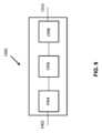
図1は、ピクチャのラスタスキャンスライスパーティション化の例を示し、ピクチャは、12個のタイル及び3つのラスタスキャンスライスに分割されている。Figure 1 shows an example of raster scan slice partitioning of a picture, where the picture is divided into 12 tiles and 3 raster scan slices.
図2は、ピクチャの長方形スライスパーティション化の例を示し、ピクチャは、24個のタイル(6つのタイル列及び4つのタイル行)及び9個の長方形スライスに分割されている。Figure 2 shows an example of rectangular slice partitioning of a picture, where the picture is divided into 24 tiles (6 tile columns and 4 tile rows) and 9 rectangular slices.
図3は、タイル及び長方形スライスにパーティション化されたピクチャの例を示し、ピクチャは、4つのタイル(2つのタイル列及び2つのタイル行)及び4つの長方形スライスに分割されている。Figure 3 shows an example of a picture partitioned into tiles and rectangular slices, where the picture is divided into four tiles (two tile columns and two tile rows) and four rectangular slices.
図4は、ピクチャのサブピクチャパーティション化の例を示し、ピクチャは、18個のタイルにパーティション化されており、左側の12個は4×4のCTUの1つのスライスをそれぞれカバーし、右側の6個のタイルは2×2のCTUの2つの垂直にスタックされたスライスをそれぞれカバーし、その結果、異なる寸法の24個のスライス及び24個のサブピクチャを生じる(各スライスはサブピクチャである)。Figure 4 shows an example of subpicture partitioning of a picture, where the picture is partitioned into 18 tiles, 12 on the left each covering one slice of a 4x4 CTU, and 6 on the right each covering two vertically stacked slices of a 2x2 CTU, resulting in 24 slices of different dimensions and 24 subpictures (each slice is a subpicture).
3.3. シーケンス内のピクチャ解像度の変更
AVC及びHEVCでは、IRAPピクチャで新たなSPSを使用する新たなシーケンスが始まらない限り、ピクチャの空間分解能は変更できない。VVCは、常にイントラコーディングされるIRAPピクチャを符号化することなく、或る位置においてシーケンス内でピクチャ解像度の変更を可能する。参照ピクチャが復号中の現在ピクチャと異なる解像度を有する場合、この機能はインター予測に使用される参照ピクチャの再サンプリングを必要とするので、この機能は、場合によっては参照ピクチャ再サンプリング(RPR, reference picture resampling)と呼ばれる。 3.3. Changing picture resolution in a sequence
In AVC and HEVC, the spatial resolution of a picture cannot be changed unless an IRAP picture starts a new sequence using a new SPS. VVC allows picture resolution changes within a sequence at some position without encoding an IRAP picture, which is always intra-coded. This function is sometimes called reference picture resampling (RPR), since it requires resampling of reference pictures used for inter prediction when the reference picture has a different resolution than the current picture being decoded.
スケーリング比は、1/2以上(参照ピクチャから現在ピクチャへの2回のダウンサンプリング)且つ8以下(8回のアップサンプリング)に制限される。参照ピクチャと現在ピクチャとの間の様々なスケーリング比を処理するために、異なる周波数カットオフを有する3つのセットの再サンプリングフィルタが指定されている。3つのセットの再サンプリングフィルタは、それぞれ1/2~1/1.75、1/1.75~1/1.25及び1/1.25~8の範囲のスケーリング比について適用される。各セットの再サンプリングフィルタは、動き補償補間フィルタの場合と同様に、ルマについて16個の位相及びクロマについて32個の位相を有する。実際には、通常のMC補間プロセスは、1/1.25~8の範囲のスケーリング比を有する再サンプリングプロセスの特別な場合である。水及び垂直のスケーリング比は、ピクチャ幅及び高さと、参照ピクチャ及び現在ピクチャについて指定された左、右、上及び下のスケーリングオフセットとに基づいて導出される。The scaling ratio is limited to be greater than or equal to 1/2 (two downsamplings from the reference picture to the current picture) and less than or equal to 8 (eight upsamplings). Three sets of resampling filters with different frequency cutoffs are specified to handle various scaling ratios between the reference picture and the current picture. The three sets of resampling filters are applied for scaling ratios ranging from 1/2 to 1/1.75, 1/1.75 to 1/1.25, and 1/1.25 to 8, respectively. Each set of resampling filters has 16 phases for luma and 32 phases for chroma, similar to the case of the motion compensation interpolation filters. In practice, the normal MC interpolation process is a special case of the resampling process with scaling ratios ranging from 1/1.25 to 8. The horizontal and vertical scaling ratios are derived based on the picture width and height and the left, right, top and bottom scaling offsets specified for the reference picture and the current picture.
HEVCとは異なる、この機能をサポートするためのVVC設計の他の側面は以下を含む。i)ピクチャ解像度及び対応する適合ウィンドウは、SPSではなくPPSでシグナリングされ、SPSでは最大ピクチャ解像度がシグナリングされる。ii)単一レイヤビットストリームについて、各ピクチャストア(1つの復号ピクチャを記憶するためのDPB内のスロット)は、最大ピクチャ解像度を有する復号ピクチャを記憶するために必要なバッファサイズを占有する。Other aspects of the VVC design to support this feature that differ from HEVC include: i) picture resolution and corresponding adaptation window are signaled in PPS instead of SPS, and maximum picture resolution is signaled in SPS. ii) For a single layer bitstream, each picture store (a slot in the DPB for storing one decoded picture) occupies the buffer size required to store a decoded picture with the maximum picture resolution.
3.4. 一般的なスケーラブルビデオコーディング(SVC, scalable video coding)及びVVCにおけるSVC
スケーラブルビデオコーディング(SVC, scalable video coding)(場合によってはビデオコーディングにおけるスケーラビリティとも呼ばれる)は、場合によっては参照レイヤ(RL, reference layer)と呼ばれるベースレイヤ(BL, base layer)、及び1つ以上のスケーラブルエンハンスメントレイヤ(EL, enhancement layer)が使用されるビデオコーディングを示す。SVCでは、ベースレイヤは、ベースレベルの品質のビデオデータを搬送できる。1つ以上のエンハンスメントレイヤは、例えば、より高い空間レベル、時間レベル、及び/又は信号対雑音(SNR, signal-to-noise)レベルをサポートするために、更なるビデオデータを搬送できる。エンハンスメントレイヤは、以前に符号化されたレイヤに対して定義されてもよい。例えば、下位レイヤはBLとして機能してもよく、上位レイヤはELとして機能してもよい。中間レイヤは、EL若しくはRLのいずれか、又はこれらの双方として機能してもよい。例えば、中間レイヤ(例えば、最下位レイヤでも最上位レイヤでもないレイヤ)は、中間レイヤの下のレイヤ、例えば、ベースレイヤ又はいずれかの介在するエンハンスメントレイヤのためのELでもよく、同時に、中間レイヤの上の1つ以上のエンハンスメントレイヤについてのRLとして機能してもよい。同様に、HEVC標準のマルチビュー又は3D拡張では、複数のビューが存在してもよく、1つのビューの情報は、他のビューの情報(例えば、動き推定、動きベクトル予測及び/又は他の冗長性)をコーディング(例えば、符号化又は復号)するために利用されてもよい。 3.4. Scalable video coding (SVC) in general and SVC in VVC
Scalable video coding (SVC), sometimes referred to as scalability in video coding, refers to video coding in which a base layer (BL), sometimes called a reference layer (RL), and one or more scalable enhancement layers (EL) are used. In SVC, the base layer can carry video data at a base level of quality. One or more enhancement layers can carry additional video data, for example to support higher spatial, temporal, and/or signal-to-noise (SNR) levels. Enhancement layers may be defined relative to previously coded layers. For example, a lower layer may function as a BL and an upper layer may function as an EL. An intermediate layer may function as either an EL or a RL, or both. For example, an intermediate layer (e.g., a layer that is neither the lowest nor the highest layer) may be an EL for a layer below the intermediate layer, e.g., a base layer or any intervening enhancement layer, and may simultaneously act as a RL for one or more enhancement layers above the intermediate layer. Similarly, in multiview or 3D extensions of the HEVC standard, there may be multiple views and information of one view may be utilized to code (e.g., encode or decode) information of other views (e.g., motion estimation, motion vector prediction, and/or other redundancy).
SVCでは、エンコーダ又はデコーダによって使用されるパラメータは、これらが利用され得るコーディングレベル(例えば、ビデオレベル、シーケンスレベル、ピクチャレベル、スライスレベル等)に基づいて、パラメータセットにグループ化される。例えば、ビットストリーム内の異なるレイヤの1つ以上のコーディングビデオシーケンスによって利用され得るパラメータは、ビデオパラメータセット(VPS, video parameter set)に含まれてもよく、コーディングビデオシーケンス内の1つ以上のピクチャによって利用されるパラメータは、シーケンスパラメータセット(SPS, sequence parameter set)に含まれてもよい。同様に、ピクチャ内の1つ以上のスライスによって利用されるパラメータは、ピクチャパラメータセット(PPS, picture parameter set)に含まれてもよく、単一のスライスに特有の他のパラメータは、スライスヘッダに含まれてもよい。同様に、特定のレイヤが所与の時間にどのパラメータセットを使用しているかの指示は、様々なコーディングレベルで提供されてもよい。In SVC, parameters used by an encoder or decoder are grouped into parameter sets based on the coding level at which they may be used (e.g., video level, sequence level, picture level, slice level, etc.). For example, parameters that may be used by one or more coding video sequences of different layers in the bitstream may be included in a video parameter set (VPS), and parameters used by one or more pictures in a coding video sequence may be included in a sequence parameter set (SPS). Similarly, parameters used by one or more slices in a picture may be included in a picture parameter set (PPS), and other parameters specific to a single slice may be included in a slice header. Similarly, an indication of which parameter set a particular layer is using at a given time may be provided at various coding levels.
VVCにおける参照ピクチャ再サンプリング(RPR, reference picture resampling)のサポートのおかげで、複数のレイヤを含むビットストリームのサポート、例えばVVCにおけるSD及びHD解像度を有する2つのレイヤは、空間スケーラビリティのサポートに必要なアップサンプリングがRPRアップサンプリングフィルタを使用するだけでよいので、更なる信号処理レベルのコーディングツールを必要とせずに設計できる。それにもかかわらず、スケーラビリティをサポートするために、(スケーラビリティをサポートしない場合と比較して)ハイレベルなシンタックスの変更が必要である。スケーラビリティのサポートは、VVCバージョン1において指定されている。AVC及びHEVCの拡張を含む、いずれかの以前のビデオコーディング標準におけるスケーラビリティのサポートとは異なり、VVCスケーラビリティの設計は、可能な限り単一レイヤのデコーダの設計にとって適したものになっている。マルチレイヤビットストリームについての復号能力は、ビットストリームに単一レイヤのみが存在するかかのように指定される。例えば、DPBサイズのような復号能力は、復号されるビットストリームのレイヤ数に依存しない方式で指定される。基本的に、単一レイヤビットストリーム用に設計されたデコーダは、マルチレイヤビットストリームを復号できるようにするために大きな変更を必要としない。AVC及びHEVCのマルチレイヤの拡張の設計と比較して、HLSの側面はいくつかの柔軟性を犠牲にしてかなり簡略化されている。例えば、CVSに存在するレイヤのそれぞれのピクチャを含めるために、IRAP AUが必要とされる。Thanks to the support of reference picture resampling (RPR) in VVC, support for bitstreams containing multiple layers, e.g., two layers with SD and HD resolution in VVC, can be designed without the need for additional signal processing level coding tools, since the upsampling required to support spatial scalability only requires the use of RPR upsampling filters. Nevertheless, high-level syntax changes (compared to the case without scalability support) are required to support scalability. Scalability support is specified in VVC version 1. Unlike scalability support in any previous video coding standard, including the extensions of AVC and HEVC, the design of VVC scalability is as suitable for single-layer decoder design as possible. Decoding capabilities for multi-layer bitstreams are specified as if only a single layer was present in the bitstream. For example, decoding capabilities such as DPB size are specified in a manner that is independent of the number of layers of the bitstream being decoded. Essentially, a decoder designed for a single-layer bitstream does not require significant modifications to be able to decode a multi-layer bitstream. Compared to the AVC and HEVC multi-layer extension designs, the HLS aspects are significantly simplified at the expense of some flexibility. For example, an IRAP AU is required to contain each picture of the layers present in the CVS.
3.5. サブピクチャに基づくビューポート依存の360°ビデオストリーミング
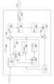
全方向ビデオとしても知られる360°ビデオのストリーミングでは、いずれかの特定の瞬間に全体の全方向ビデオ球体のサブセット(すなわち、現在のビューポート)のみがユーザに対してレンダリングされるが、ユーザはいつでも頭を回して表示方向を変更し、結果として現在のビューポートを変更できる。ユーザが突然球体上のどこかに表示方向を変更した場合に備えて、現在のビューポートでカバーされていない領域の少なくともいくつかの低品質の表現をクライアントにおいて利用可能にさせ、ユーザにレンダリングする準備をさせることが望まれるが、全方向ビデオの高品質表現は、現在の使用のためにレンダリングされている現在のビューポートにのみ必要である。全体の全方位ビデオの高品質表現を適切な粒度でサブピクチャに分割することは、このような最適化を可能にする。VVCを使用すると、2つの表現が互いに独立した2つのレイヤとして符号化できる。 3.5. Viewport-Dependent 360° Video Streaming Based on Subpictures In streaming of 360° video, also known as omnidirectional video, only a subset of the entire omnidirectional video sphere (i.e. the current viewport) is rendered to the user at any given moment, but the user can turn his head at any time to change the viewing orientation and, consequently, the current viewport. In case the user suddenly changes the viewing orientation somewhere on the sphere, it is desirable to have a lower quality representation of at least some of the areas not covered by the current viewport available at the client and ready to be rendered to the user, while a high-quality representation of the omnidirectional video is only needed for the current viewport being rendered for the current use. Partitioning the high-quality representation of the entire omnidirectional video into subpictures with the right granularity allows such optimization. With VVC, the two representations can be coded as two layers independent of each other.
典型的なサブピクチャに基づくビューポート依存の360°ビデオ配信方式が図11に示されており、フルビデオの高解像度表現はサブピクチャで構成されるが、フルビデオの低解像度表現はサブピクチャを使用せず、高解像度表現よりも少ない頻度のランダムアクセスポイントでコーディングできる。クライアントは低解像度のフルビデオを受信し、高解像度のビデオについては、現在のビューポートをカバーするサブピクチャのみを受信して復号する。A typical sub-picture based viewport-dependent 360° video delivery scheme is shown in Figure 11, where a high-resolution representation of the full video is composed of sub-pictures, while a low-resolution representation of the full video does not use sub-pictures and can be coded with less frequent random access points than the high-resolution representation. The client receives the full low-resolution video, and for the high-resolution video it receives and decodes only the sub-pictures that cover the current viewport.
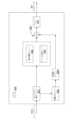
最新のVVCドラフト仕様は、図12に示すように、改善された360°ビデオコーディング方式もサポートしている。図11に示す手法と比較したときの唯一の違いは、レイヤ間予測(ILP, inter-layer prediction)が図12に示す手法に適用されることである。The latest VVC draft specification also supports an improved 360° video coding scheme, as shown in Figure 12. The only difference compared to the scheme shown in Figure 11 is that inter-layer prediction (ILP) is applied in the scheme shown in Figure 12.
3.6. パラメータセット
AVC、HEVC及びVVCは、パラメータセットを指定する。パラメータセットのタイプは、SPS、PPS、APS及びVPSを含む。SPS及びPPSは、AVC、HEVC及びVVCの全てでサポートされる。VPSはHEVCから導入され、HEVC及びVVCの双方に含まれる。APSは、AVC又はHEVCには含まれないが、最新のVVCドラフトテキストに含まれている。 3.6. Parameter Set
AVC, HEVC and VVC specify parameter sets. Parameter set types include SPS, PPS, APS and VPS. SPS and PPS are all supported by AVC, HEVC and VVC. VPS was introduced by HEVC and is included in both HEVC and VVC. APS is not included in AVC or HEVC but is included in the latest VVC draft text.
SPSはシーケンスレベルのヘッダ情報を搬送するように設計され、PPSはまれに変化するピクチャレベルのヘッダ情報を搬送するように設計されている。SPS及びPPSでは、シーケンス又はピクチャ毎にまれに変化する情報が繰り返される必要がないので、この情報の冗長なシグナリングが回避できる。さらに、SPS及びPPSの使用は、重要なヘッダ情報の帯域外送信を可能にし、冗長送信の必要性を回避するだけでなく、エラー耐性も改善する。SPS is designed to carry sequence-level header information, while PPS is designed to carry picture-level header information that changes infrequently. With SPS and PPS, infrequently changing information does not need to be repeated for every sequence or picture, thus avoiding redundant signaling of this information. Furthermore, the use of SPS and PPS allows out-of-band transmission of critical header information, not only avoiding the need for redundant transmissions, but also improving error resilience.
VPSは、マルチレイヤビットストリームの全てのレイヤに共通するシーケンスレベルのヘッダ情報を搬送するために導入されている。VPS is introduced to carry sequence-level header information that is common to all layers of a multi-layer bitstream.
APSは、コーディングにかなりのビットを必要とし、複数のピクチャによって共有でき、シーケンスにおいて非常に多くの異なるバリエーションが存在し得るようなピクチャレベル又はスライスレベルの情報を搬送するために導入されている。APS is introduced to carry picture-level or slice-level information that requires significant bits to code, can be shared by multiple pictures, and can exist in many different variations in a sequence.
3.7. サブピクチャサブビットストリーム抽出プロセス
最新のVVCテキストのC.7節に加えて、Bytedance IDF P2005612001H_v0における提案の変更のサブピクチャサブビットストリーム抽出プロセスは以下の通りである。
C.7 サブピクチャサブビットストリーム抽出プロセス
このプロセスへの入力は、ビットストリームinBitstream、ターゲットOLSインデックスtargetOlsIdx、ターゲット最高TemporalId値tIdTarget、及び0以上NumLayersInOls[targetOLsIdx]-1以下のiについてのターゲットサブピクチャインデックス値subpicIdxTarget[i]のリストである。
このプロセスの出力は、サブビットストリームoutBitstreamである。
入力ビットストリームについてのビットストリーム適合性の要件は、以下の条件の全てを満たすいずれかの出力サブビットストリームが適合ビットストリームであることである。
- 出力サブビットストリームは、ビットストリーム、VPSによって指定されたOLSのリストへのインデックスに等しいtargetOlsIdx、0以上vps_max_sublayers_minus1以下の範囲内のいずれかの値に等しいtIdTarget、及び以下の条件を満たす0以上NumLayersInOls[targetOLsIdx]-1以下のiについてのリストsubpicIdxTarget[i]を入力として、この節で指定されたプロセスの出力である。
- 第targetOLsIdxのOLS内の全てのレイヤは、同じ空間分解能、sps_num_subpics_minus1について同じ値及び同じサブピクチャレイアウトを有し、全て
のサブピクチャは1に等しいsps_subpic_treated_as_pic_flag[]を有する。
- iの全ての値についてのsubpicIdxTarget[i]の値は同じであり、0以上sps_num_subpics_minus1以下の範囲内の特定の値に等しい。
- NumLayersInOls[targetOlsIdx]が1よりも大きく、sps_num_subpics_minus1が0よりも大きい場合、サブピクチャレベル情報SEIメッセージは、1に等しいsn_ols_flagを有するスケーラブルネスト化SEIメッセージに存在するものとし、NestingOlsIdx[i]は0以上sn_num_olss_minus1以下の範囲内のiの1つの値についてtargetOlsIdxに等しい。
マルチレイヤOLSでの使用のために、SLI SEIメッセージは、スケーラブルネスト化SEIメッセージに含まれるものとし、特定のOLS又は特定のOLS内の全てのレイヤに適用されるようにスケーラブルネスト化SEIメッセージに示されるものとする。
- 出力サブビットストリームは、リストLayerIdInOls[targetOlsIdx]内のnuh_layer_id値のそれぞれに等しいnuh_layer_idを有する少なくとも1つのVCL NALユニットを含む。
- 出力サブビットストリームは、tIdTargetに等しいTemporalIdを有する少なくとも1つのVCL NALユニットを含む。
注-適合ビットストリームは、0に等しいTemporalIdを有する1つ以上のコーディングされたスライスNALユニットを含むが、0に等しいnuh_layer_idを有するコーディングされたスライスNALユニットを含む必要はない。
- 出力サブビットストリームは、0以上NumLayersInOls[targetOlsIdx]-1以下の範囲内のそれぞれのiについてLayerIdInOls[targetOlsIdx][i]に等しいnuh_layer_idを有し且つSubpicIdVal[subpicIdxTarget[i]]に等しいsh_subpic_idを有する少なくとも1つのVCL NALユニットを含む。
出力サブビットストリームoutBitstreamは以下のように導出される。
- Annex C.6において指定されたサブビットストリーム抽出プロセスは、inBitstream、targetOlsIdx及びtIdTargetを入力として呼び出され、プロセスの出力はoutBitstreamに割り当てられる。
- 0以上NumLayersInOls[targetOLsIdx]-1以下の範囲のiのそれぞれ値について、outBitstreamから、LayerIdInOls[targetOLsIdx][i]に等しいnuh_layer_idを有し且つSubpicIdVal[subpicIdxTarget[i]]に等しくないsh_subpic_idを有する全てのVCL NALユニットと、これらに関連するフィラー(filler)データNALユニット及びフィラーペイロードSEIメッセージを含むSEI NALユニットとを削除する。
- sli_cbr_constraint_flagが0に等しい場合、FD_NUTに等しいnal_unit_typeを有する全てのNALユニットと、フィラーペイロードSEIメッセージを含むSEI NALユニットとを削除する。
- この仕様において指定されていない何らかの外部手段がサブビットストリームoutBitstreamの置換パラメータセットを提供するために利用可能である場合、全てのパラメータセットを置換パラメータセットに置き換える。
- そうでなく、サブピクチャレベル情報SEIメッセージがinBitstreamに存在する場合、以下が適用される。
- 全ての参照されるVPS NALユニット内のprofile_tier_level()シンタックス構造のリストの第vps_ols_ptl_idx[targetOlsIdx]のエントリ内のgeneral_level_idcの値を、subpicIdxに等しいサブピクチャインデックスを有するサブピクチャから構成されるサブピクチャのセットについて、式D.11で導出されるSubpicSetLevelIdcに等しくなるように書き換える。
- VCL HRDパラメータ又はNAL HRDパラメータが存在する場合、全ての参照されるVPS NALユニット内の第vps_ols_hrd_idx[MultiLayerOlsIdx[targetOlsIdx]]のols_hrd_parameters()シンタックス構造と、第iのレイヤによって参照される全てのSPS NALユニット内のols_hrd_parameters()シンタックス構造とにおいて第jのCPBのcpb_size_value_minus1[tIdTarget][j]及びbit_rate_value_minus1[tIdTarget][j]のそれぞれの値を、これらがそれぞれ式D.6によって導出されるSubpicCpbSizeVcl[SubpicSetLevelIdx][subpicIdx]及びSubpicCpbSizeNal[SubpicSetLevelIdx][subpicIdx]と、それぞれ式D.8及びD.9によって導出されるSubpicBitrateVcl[SubpicSetLevelIdx][subpicIdx]及びSubpicBitrateNal[SubpicSetLevelIdx][subpicIdx]とに対応するように書き換え、SubpicSetLevelIdxは、subpicIdxに等しいサブピクチャインデックスを有するサブピクチャについて式D.11によって導出され、jは0以上hrd_cpb_cnt_minus1以下の範囲内にあり、iは0以上NumLayersInOls[targetOlsIdx]-1の範囲内にある。
- 0以上NumLayersInOls[targetOlsIdx]-1以下の範囲内のiのそれぞれの値について、以下が適用される。
- 変数spIdxはsubpicIdxTarget[i]に等しく設定される。
- 1に等しいsps_ptl_dpb_hrd_params_present_flagを有する全ての参照されるSPS NALユニット内のprofile_tier_level()シンタックス構造内のgeneral_level_idcの値を、spIdxに等しいサブピクチャインデックスを有するサブピクチャから構成されるサブピクチャのセットについて、式D.11によって導出されるSubpicSetLevelIdcに等しくなるように書き換える。
- 変数subpicWidthInLumaSamples及びsubpicHeightInLumaSamplesは以下のように導出される。
subpicWidthInLumaSamples=min((sps_subpic_ctu_top_left_x[spIdx]+sps_subpic_width_minus1[spIdx]+1)*CtbSizeY,pps_pic_width_in_luma_samples)-sps_subpic_ctu_top_left_x[spIdx]*CtbSizeY (C.24)
subpicHeightInLumaSamples=min((sps_subpic_ctu_top_left_y[spIdx]+sps_subpic_height_minus1[spIdx]+1)*CtbSizeY,pps_pic_height_in_luma_samples)-sps_subpic_ctu_top_left_y[spIdx]*CtbSizeY (C.25)
- 全ての参照されるSPS NALユニット内のsps_pic_width_max_in_luma_samples及びsps_pic_height_max_in_luma_samplesの値と、全ての参照されるPPS NALユニット内のpps_pic_width_in_luma_samples及びpps_pic_height_in_luma_samplesの値とを、それぞれsubpicWidthInLumaSamples及びsubpicHeightInLumaSamplesに等しくなるように書き換える。
- 全ての参照されるSPS NALユニット内のsps_num_subpics_minus1と、全ての参照されるPPS NALユニット内のpps_num_subpics_minus1の値とを0に書き換える。
- 存在する場合には全ての参照されるSPS NALユニット内のシンタックスエレメントsps_subpic_ctu_top_left_x[spIdx]及びsps_subpic_ctu_top_left_y[spIdx]を0に書き換える。
- 全ての参照されるSPS NALユニット内で、spIdxに等しくないそれぞれのjについて、シンタックスエレメントsps_subpic_ctu_top_left_x[j]、sps_subpic_ctu_top_left_y[j]、sps_subpic_width_minus1[j]、sps_subpic_height_minus1[j]、sps_subpic_treated_as_pic_flag[j]、sps_loop_filter_across_subpic_enabled_flag[j]及びsps_subpic_id[j]を削除する。
- タイル及びスライスのシグナリングのために全ての参照されるPPS内のシンタックスエレメントを書き換え、spIdxに等しいサブピクチャインデックスを有するサブピクチャに関連しない全てのタイル行、タイル列及びスライスを削除する。
- 変数subpicConfWinLeftOffset、subpicConfWinRightOffset、subpicConfWinTopOffset及びsubpicConfWinBottomOffsetは以下のように導出される。
subpicConfWinLeftOffset=sps_subpic_ctu_top_left_x[spIdx]==0?sps_conf_win_left_offset:0 (C.26)
subpicConfWinRightOffset=(sps_subpic_ctu_top_left_x[spIdx]+sps_subpic_width_minus1[spIdx]+1)*CtbSizeY>=sps_pic_width_max_in_luma_samples?sps_conf_win_right_offset:0 (C.27)
subpicConfWinTopOffset=sps_subpic_ctu_top_left_y[spIdx]==0?sps_conf_win_top_offset:0 (C.28)
subpicConfWinBottomOffset=(sps_subpic_ctu_top_left_y[spIdx]+sps_subpic_height_minus1[spIdx]+1)*CtbSizeY>=sps_pic_height_max_in_luma_samples?sps_conf_win_bottom_offset:0 (C.29)
ここで、上記の式におけるsps_subpic_ctu_top_left_x[spIdx]、sps_subpic_width_minus1[spIdx]、sps_subpic_ctu_top_left_y[spIdx]、sps_subpic_height_minus1[spIdx]、sps_pic_width_max_in_luma_samples、sps_pic_height_max_in_luma_samples、sps_conf_win_left_offset、sps_conf_win_right_offset、sps_conf_win_top_offset及びsps_conf_win_bottom_offsetは、書き換え前の元のSPSのものである。
- 全ての参照されるSPS NALユニット内のsps_conf_win_left_offset、sps_conf_win_right_offset、sps_conf_win_top_offset及びsps_conf_win_bottom_offsetの値と、全ての参照されるPPS NALユニット内のpps_conf_win_left_offset、pps_conf_win_right_offset、pps_conf_win_top_offset及びpps_conf_win_bottom_offsetの値とを、それぞれsubpicConfWinLeftOffset、subpicConfWinRightOffset、subpicConfWinTopOffset及びsubpicConfWinBottomOffsetに等しくなるように書き換える。
- 変数subpicScalWinLeftOffset、subpicScalWinRightOffset、subpicScalWinTopOffset及びsubpicScalWinBotOffsetは以下のように導出される。
subpicScalWinLeftOffset=pps_scaling_win_left_offset-sps_subpic_ctu_top_left_x[spIdx]*CtbSizeY/SubWidthC (C.30)
rightSubpicBd=(sps_subpic_ctu_top_left_x[spIdx]+sps_subpic_width_minus1[spIdx]+1)*CtbSizeY
subpicScalWinRightOffset=(rightSubpicBd>=sps_pic_width_max_in_luma_samples)?pps_scaling_win_right_offset:pps_scaling_win_right_offset-(sps_pic_width_max_in_luma_samples-rightSubpicBd)/SubWidthC (C.31)
subpicScalWinTopOffset=pps_scaling_win_top_offset-sps_subpic_ctu_top_left_y[spIdx]*CtbSizeY/SubHeightC (C.32)
botSubpicBd=(sps_subpic_ctu_top_left_y[spIdx]+sps_subpic_height_minus1[spIdx]+1)*CtbSizeY
subpicScalWinBotOffset=(botSubpicBd>=sps_pic_height_max_in_luma_samples)?pps_scaling_win_bottom_offset:pps_scaling_win_bottom_offset-(sps_pic_height_max_in_luma_samples-botSubpicBd)/SubHeightC (C.33)
ここで、上記の式におけるsps_subpic_ctu_top_left_x[spIdx]、sps_subpic_width_minus1[spIdx]、sps_subpic_ctu_top_left_y[spIdx]、sps_subpic_height_minus1[spIdx]、sps_pic_width_max_in_luma_samples及びsps_pic_height_max_in_luma_samplesは、書き換え前の元のSPSのものであり、上記のpps_scaling_win_left_offset、pps_scaling_win_right_offset、pps_scaling_win_top_offset及びpps_scaling_win_bottom_offsetは、書き換え前の元のPPSのものである。
- 全ての参照されるPPS NALユニット内のpps_scaling_win_left_offset、pps_scaling_win_right_offset、pps_scaling_win_top_offset及びpps_scaling_win_bottom_offsetの値を、それぞれsubpicScalWinLeftOffset、subpicScalWinRightOffset、subpicScalWinTopOffset及びsubpicScalWinBotOffsetに等しくなるように書き換える。
- sli_cbr_constraint_flagが1に等しい場合、0以上hrd_cpb_cnt_minus1以下の範囲内のjにおいて、全ての参照されるVPS NALユニット及びSPS NALユニット内の第vps_ols_hrd_idx[MultiLayerOlsIdx[targetOlsIdx]]のols_hrd_parameters()シンタックス構造内の第jのCPBのcbr_flag[tIdTarget][j]を1に等しく設定する。そうでない場合(sli_cbr_constraint_flagが0に等しい場合)、cbr_flag[tIdTarget][j]を0に等しく設定する。
- outBitstreamが、outBitstreamに適用可能な、1に等しいsn_ols_flag及び1に等しいsn_subpic_flagを有するスケーラブルネスト化SEIメッセージを含むSEI NALユニットを含む場合、スケーラブルネスト化SEIメッセージから、1(PT)、130(DUI)又は132(復号ピクチャハッシュ)に等しいpayloadTypeを有する適切なスケーラブルネスト化されていないSEIメッセージを抽出し、抽出されたSEIメッセージをoutBitstreamに配置する。
3.7. Subpicture Sub-bitstream Extraction Process In addition to the latest VVC text, section C.7, the subpicture sub-bitstream extraction process of the proposed changes in Bytedance IDF P2005612001H_v0 is as follows:
C.7 Subpicture Sub-Bitstream Extraction Process The inputs to this process are the bitstream inBitstream, a target OLS index targetOlsIdx, a target highest TemporalId value tIdTarget, and a list of target subpicture index values subpicIdxTarget[i] for i 0 to NumLayersInOls[targetOLsIdx]-1 inclusive.
The output of this process is the sub-bitstream outBitstream.
The bitstream conformance requirement for an input bitstream is that any output sub-bitstream that satisfies all of the following conditions is a conforming bitstream:
- The output sub-bitstream is the output of the process specified in this section, which takes as input the bitstream, targetOlsIdx equal to an index into the list of OLS specified by the VPS, tIdTarget equal to any value in the range 0 to vps_max_sublayers_minus1 inclusive, and a list subpicIdxTarget[i], for i inclusive, 0 to NumLayersInOls[targetOLsIdx]-1 inclusive, such that
- All layers in the OLS with targetOLsIdx have the same spatial resolution, the same value for sps_num_subpics_minus1 and the same subpicture layout, and all subpictures have sps_subpic_treated_as_pic_flag[] equal to 1.
- The value of subpicIdxTarget[i] for all values of i is the same and is equal to a specific value in the range from 0 to sps_num_subpics_minus1, inclusive.
- if NumLayersInOls[targetOlsIdx] is greater than 1 and sps_num_subpics_minus1 is greater than 0, then a sub-picture level information SEI message shall be present in a scalable nesting SEI message with sn_ols_flag equal to 1 and NestingOlsIdx[i] is equal to targetOlsIdx for one value of i in the range from 0 to sn_num_olss_minus1, inclusive.
For use in a multi-layer OLS, the SLI SEI message shall be included in a scalable nested SEI message and shall be indicated in the scalable nested SEI message as applying to a particular OLS or all layers within a particular OLS.
- The output sub-bitstream contains at least one VCL NAL unit with nuh_layer_id equal to each of the nuh_layer_id values in the list LayerIdInOls[targetOlsIdx].
- The output sub-bitstream contains at least one VCL NAL unit with TemporalId equal to tIdTarget.
NOTE - A conforming bitstream contains one or more coded slice NAL units with TemporalId equal to 0, but is not required to contain a coded slice NAL unit with nuh_layer_id equal to 0.
- The output sub-bitstream contains at least one VCL NAL unit with nuh_layer_id equal to LayerIdInOls[targetOlsIdx][i] and with sh_subpic_id equal to SubpicIdVal[subpicIdxTarget[i]], for each i in the range from 0 to NumLayersInOls[targetOlsIdx] - 1, inclusive.
The output sub-bitstream outBitstream is derived as follows.
- The sub-bitstream extraction process specified in Annex C.6 is called with inBitstream, targetOlsIdx and tIdTarget as inputs, and the output of the process is assigned to outBitstream.
- for each value of i in the range 0 to NumLayersInOls[targetOLsIdx]-1, inclusive, remove from outBitstream all VCL NAL units with nuh_layer_id equal to LayerIdInOls[targetOLsIdx][i] and sh_subpic_id not equal to SubpicIdVal[subpicIdxTarget[i]], as well as their associated filler data NAL units and SEI NAL units containing filler payload SEI messages.
- If sli_cbr_constraint_flag is equal to 0, remove all NAL units with nal_unit_type equal to FD_NUT and SEI NAL units that contain filler payload SEI messages.
- If some external means not specified in this specification are available to provide a replacement parameter set for the sub-bitstream outBitstream, replace all parameter sets with the replacement parameter set.
- Otherwise, if a Sub-picture level information SEI message is present in inBitstream, the following applies:
- Rewrite the value of general_level_idc in the entry for vps_ols_ptl_idx[targetOlsIdx] of the list of profile_tier_level() syntax structures in all referenced VPS NAL units to be equal to the SubpicSetLevelIdc derived in equation D.11 for the subpicture set consisting of the subpicture with a subpicture index equal to subpicIdx.
- if VCL HRD parameters or NAL HRD parameters are present, the respective values of cpb_size_value_minus1[tIdTarget][j] and bit_rate_value_minus1[tIdTarget][j] of the jth CPB in the ols_hrd_parameters() syntax structure of vps_ols_hrd_idx[MultiLayerOlsIdx[targetOlsIdx]] in all referenced VPS NAL units and in the ols_hrd_parameters() syntax structures in all SPS NAL units referenced by the i-th layer shall be converted to SubpicCpbSizeVcl[SubpicSetLevelIdx][subpicIdx] and SubpicCpbSizeNal[SubpicSetLevelIdx][subpicIdx], which are derived by Equation D.6, respectively, and to SubpicCpbSizeVcl[SubpicSetLevelIdx][subpicIdx] and SubpicCpbSizeNal[SubpicSetLevelIdx][subpicIdx], which are derived by Equation D.8 and D.9, respectively. where SubpicSetLevelIdx is derived according to equation D.11 for the subpicture with subpicture index equal to subpicIdx, j is in the range 0 to hrd_cpb_cnt_minus1, inclusive, and i is in the range 0 to NumLayersInOls[targetOlsIdx]-1.
- For each value of i in the range 0 to NumLayersInOls[targetOlsIdx]-1, inclusive:
- The variable spIdx is set equal to subpicIdxTarget[i].
- Rewrite the value of general_level_idc in the profile_tier_level() syntax structure in all referenced SPS NAL units with sps_ptl_dpb_hrd_params_present_flag equal to 1 to be equal to the SubpicSetLevelIdc derived by equation D.11 for the subpicture set consisting of the subpicture with subpicture index equal to spIdx.
- The variables subpicWidthInLumaSamples and subpicHeightInLumaSamples are derived as follows:
subpicWidthInLumaSamples=min((sps_subpic_ctu_top_left_x[spIdx]+sps_subpic_width_minus1[spIdx]+1)*CtbSizeY,pps_pic_width_in_luma_samples)-sps_subpic_ctu_top_left_x[spIdx]*CtbSizeY (C.24)
subpicHeightInLumaSamples=min((sps_subpic_ctu_top_left_y[spIdx]+sps_subpic_height_minus1[spIdx]+1)*CtbSizeY,pps_pic_height_in_luma_samples)-sps_subpic_ctu_top_left_y[spIdx]*CtbSizeY (C.25)
- Rewrite the values of sps_pic_width_max_in_luma_samples and sps_pic_height_max_in_luma_samples in all referenced SPS NAL units and the values of pps_pic_width_in_luma_samples and pps_pic_height_in_luma_samples in all referenced PPS NAL units to be equal to subpicWidthInLumaSamples and subpicHeightInLumaSamples, respectively.
- Rewrite the values of sps_num_subpics_minus1 in all referenced SPS NAL units and pps_num_subpics_minus1 in all referenced PPS NAL units to 0.
- If present, replace the syntax elements sps_subpic_ctu_top_left_x[spIdx] and sps_subpic_ctu_top_left_y[spIdx] with 0 in all referenced SPS NAL units.
- In all referenced SPS NAL units, for each j not equal to spIdx, remove the syntax elements sps_subpic_ctu_top_left_x[j], sps_subpic_ctu_top_left_y[j], sps_subpic_width_minus1[j], sps_subpic_height_minus1[j], sps_subpic_treated_as_pic_flag[j], sps_loop_filter_across_subpic_enabled_flag[j], and sps_subpic_id[j].
- Rewrite syntax elements in all referenced PPS for tile and slice signaling, removing all tile rows, tile columns and slices that are not associated with the subpicture with subpicture index equal to spIdx.
The variables subpicConfWinLeftOffset, subpicConfWinRightOffset, subpicConfWinTopOffset, and subpicConfWinBottomOffset are derived as follows:
subpicConfWinLeftOffset=sps_subpic_ctu_top_left_x[spIdx]==0?sps_conf_win_left_offset:0 (C.26)
subpicConfWinRightOffset=(sps_subpic_ctu_top_left_x[spIdx]+sps_subpic_width_minus1[spIdx]+1)*CtbSizeY>=sps_pic_width_max_in_luma_samples?sps_conf_win_right_offset:0 (C.27)
subpicConfWinTopOffset=sps_subpic_ctu_top_left_y[spIdx]==0?sps_conf_win_top_offset:0 (C.28)
subpicConfWinBottomOffset=(sps_subpic_ctu_top_left_y[spIdx]+sps_subpic_height_minus1[spIdx]+1)*CtbSizeY>=sps_pic_height_max_in_luma_samples?sps_conf_win_bottom_offset:0 (C.29)
Here, sps_subpic_ctu_top_left_x[spIdx], sps_subpic_width_minus1[spIdx], sps_subpic_ctu_top_left_y[spIdx], sps_subpic_height_minus1[spIdx], sps_pic_width_max_in_luma_samples, sps_pic_height_max_in_luma_samples, sps_conf_win_left_offset, sps_conf_win_right_offset, sps_conf_win_top_offset and sps_conf_win_bottom_offset in the above equation are those of the original SPS before being rewritten.
- Rewrite the values of sps_conf_win_left_offset, sps_conf_win_right_offset, sps_conf_win_top_offset, and sps_conf_win_bottom_offset in all referenced SPS NAL units and the values of pps_conf_win_left_offset, pps_conf_win_right_offset, pps_conf_win_top_offset, and pps_conf_win_bottom_offset in all referenced PPS NAL units to be equal to subpicConfWinLeftOffset, subpicConfWinRightOffset, subpicConfWinTopOffset, and subpicConfWinBottomOffset, respectively.
The variables subpicScalWinLeftOffset, subpicScalWinRightOffset, subpicScalWinTopOffset, and subpicScalWinBotOffset are derived as follows:
subpicScalWinLeftOffset=pps_scaling_win_left_offset-sps_subpic_ctu_top_left_x[spIdx]*CtbSizeY/SubWidthC (C.30)
rightSubpicBd=(sps_subpic_ctu_top_left_x[spIdx]+sps_subpic_width_minus1[spIdx]+1)*CtbSizeY
subpicScalWinRightOffset=(rightSubpicBd>=sps_pic_width_max_in_luma_samples)?pps_scaling_win_right_offset:pps_scaling_win_right_offset-(sps_pic_width_max_in_luma_samples-rightSubpicBd)/SubWidthC (C.31)
subpicScalWinTopOffset=pps_scaling_win_top_offset-sps_subpic_ctu_top_left_y[spIdx]*CtbSizeY/SubHeightC (C.32)
botSubpicBd=(sps_subpic_ctu_top_left_y[spIdx]+sps_subpic_height_minus1[spIdx]+1)*CtbSizeY
subpicScalingWinBotOffset=(botSubpicBd>=sps_pic_height_max_in_luma_samples)?pps_scaling_win_bottom_offset:pps_scaling_win_bottom_offset-(sps_pic_height_max_in_luma_samples-botSubpicBd)/SubHeightC (C.33)
Here, sps_subpic_ctu_top_left_x[spIdx], sps_subpic_width_minus1[spIdx], sps_subpic_ctu_top_left_y[spIdx], sps_subpic_height_minus1[spIdx], sps_pic_width_max_in_luma_samples and sps_pic_height_max_in_luma_samples in the above equation are those of the original SPS before the rewrite, and pps_scaling_win_left_offset, pps_scaling_win_right_offset, pps_scaling_win_top_offset and pps_scaling_win_bottom_offset above are those of the original PPS before the rewrite.
- Rewrite the values of pps_scaling_win_left_offset, pps_scaling_win_right_offset, pps_scaling_win_top_offset, and pps_scaling_win_bottom_offset in all referenced PPS NAL units to be equal to subpicScalWinLeftOffset, subpicScalWinRightOffset, subpicScalWinTopOffset, and subpicScalWinBotOffset, respectively.
- if sli_cbr_constraint_flag is equal to 1, set cbr_flag[tIdTarget][j] of the j-th CPB in the ols_hrd_parameters() syntax structure of vps_ols_hrd_idx[MultiLayerOlsIdx[targetOlsIdx]] in all referenced VPS NAL units and SPS NAL units, for j in the range from 0 to hrd_cpb_cnt_minus1, inclusive, to 1. Otherwise (sli_cbr_constraint_flag is equal to 0), set cbr_flag[tIdTarget][j] to 0.
- if outBitstream contains a SEI NAL unit containing a scalable nested SEI message with sn_ols_flag equal to 1 and sn_subpic_flag equal to 1 applicable to outBitstream, extract from the scalable nested SEI message the appropriatescalable non-nested SEI message with payloadType equal to 1 (PT), 130 (DUI) or 132 (decoded picture hash) and place the extracted SEI message in outBitstream.
4. 開示の技術的解決策により解決される技術的問題
サブピクチャサブビットストリーム抽出プロセスの最新の設計は以下の問題を有する。
1) 出力ビットストリームに適用されない1に等しいsn_subpic_flagを有するスケーラブルネスト化SEIメッセージにおいて、スケーラブルネスト化されたSEIメッセージを含むSEI NALユニットは、出力ビットストリームから削除されるべきである。
2) サブピクチャシーケンスを識別するためのサブピクチャインデックスは、ピクチャ当たり1つのサブピクチャのみを有するレイヤではなく、ピクチャ当たり複数のサブピクチャを有するレイヤにおける抽出対象のサブピクチャのサブピクチャインデックスであるべきである。
3) 0以上tIdTarget-1以下の範囲内のkについてsublayer_level_idc[k]の書き換えが欠落しており、参照されるVPS及び/又は参照されるSPSに対してどの条件でレベル情報の書き換えが実行されるべきかが明確に指定されていない。
4) 0以上tIdTarget-1以下の範囲内のkについてcpb_size_value_minus1[k][j]及びbit_rate_value_minus1[k][j]の書き換えが欠落しており、参照されるVPS及び/又は参照されるSPSに対してどの条件でCPBサイズ及びビットレート情報の書き換えが実行されるべきかが明確に指定されていない。
5) 参照されるVPS及び/又は参照されるSPSに対してどの条件でcbr_flag[tIdTarget][j]の書き換えが実行されるべきかが明確に指定されていない。
6) スケーラブルネスト化されたSEIメッセージをスケーラブルネスト化されていないSEIメッセージにする最後のステップは複数の問題を有する。
a. 復号ピクチャハッシュSEIメッセージがスケーラブルネスト化SEIメッセージに含まれる場合、sn_ols_flagの値は0になる必要があるが、最後のステップの現在のテキストはsn_ols_flagが1であることを仮定している。
b. 1に等しいsn_ols_flag及び1に等しいsn_subpic_flagを有する場合のSLI及びBP SEIメッセージはカバーされていない。
c. 0に等しいsn_ols_flag及び1に等しいsn_subpic_flagを有する場合のSEIメッセージはカバーされていない。
d. 結果のスケーラブルネスト化されていないSEIメッセージが出力ビットストリームのどこに配置されるべきであるか(SEI NALユニット内で、SEI NALユニットがどれであるべきか)が指定されていない。
e. 元のコンテナSEI NALユニットは、出力ビットストリームから削除されるべきである。
4. Technical Problems Solved by the Disclosed Technical Solution Current designs of the sub-picture sub-bitstream extraction process have the following problems:
1) For a scalable nested SEI message with sn_subpic_flag equal to 1 that does not apply to the output bitstream, the SEI NAL unit containing the scalablenested SEI message should be removed from the output bitstream.
2) The sub-picture index for identifying a sub-picture sequence should be the sub-picture index of the sub-picture to be extracted in a layer with multiple sub-pictures per picture, not in a layer with only one sub-picture per picture.
3) The rewrite of sublayer_level_idc[k] for k in the range 0 to tIdTarget-1 is missing, and it is not clearly specified under which conditions the rewrite of level information should be performed for the referenced VPS and/or the referenced SPS.
4) The rewrite of cpb_size_value_minus1[k][j] and bit_rate_value_minus1[k][j] for k in the range 0 to tIdTarget-1 is missing, and it is not clearly specified under which conditions the rewrite of CPB size and bitrate information should be performed for the referenced VPS and/or the referenced SPS.
5) It is not clearly specified under what conditions the rewriting of cbr_flag[tIdTarget][j] should be performed for the referenced VPS and/or the referenced SPS.
6) The final step of turning ascalable nested SEI message into ascalable non-nested SEI message has several problems.
a. When a decoded picture hash SEI message is included in a scalable nested SEI message, the value of sn_ols_flag must be 0, but the current text in the last step assumes that sn_ols_flag is 1.
b. SLI and BP SEI messages with sn_ols_flag equal to 1 and sn_subpic_flag equal to 1 are not covered.
c. SEI messages with sn_ols_flag equal to 0 and sn_subpic_flag equal to 1 are not covered.
d. It is not specified where the resultingscalable non-nested SEI message should be placed in the output bitstream (within an SEI NAL unit, which SEI NAL unit should it be).
e. The original container SEI NAL unit should be removed from the output bitstream.
5. 解決策及び実施形態の一覧
上記の問題等を解決するために、以下に要約される方法が開示される。解決策の項目は、一般的な概念を説明するための例として考えられるべきであり、狭い意味で解釈されるべきではない。さらに、これらの項目は個別に適用でき、或いは、いずれかの方式で組み合わせることもできる。
1) 問題1を解決するために、サブピクチャサブビットストリーム抽出プロセスにおいて、出力ビットストリームに適用されないスケーラブルネスト化されたSEIメッセージを含むSEI NALユニットは出力ビットストリームから削除するように指定されてもよい。
2) 問題2を解決するために、サブピクチャサブビットストリーム抽出プロセスにおいて、以下が指定されてもよい。サブピクチャシーケンスを識別するためのサブピクチャインデックスは、ピクチャ当たり1つのサブピクチャのみを有するレイヤではなく、ピクチャ当たり複数のサブピクチャを有するレイヤにおいて、抽出対象のサブピクチャのサブピクチャインデックスとして指定される。
3) 問題3を解決するために、サブピクチャサブビットストリーム抽出プロセスにおいて、以下が指定されてもよい。存在する場合には参照されるVPS内で、また、NumLayersInOls[targetOLsIdx]が0に等しい場合には参照されるSPS内で、0以上tIdTarget-1以下の範囲内のkについてgeneral_level_idc及びsublayer_level_idc[k]の双方を、適切な値(例えば、本文献に記載される値)に書き換える。
4) 問題4を解決するために、サブピクチャサブビットストリーム抽出プロセスにおいて、以下が指定されてもよい。存在する場合には参照されるVPS内で、また、NumLayersInOls[targetOLsIdx]が0に等しい場合には参照されるSPS内で、0以上tIdTarget以下の範囲内のkの全ての値についてcpb_size_value_minus1[k][j]及びbit_rate_value_minus1[k][j]を、適切な値(例えば、本文献に記載される値)に書き換える。
5) 問題5を解決するために、サブピクチャサブビットストリーム抽出プロセスにおいて、以下が指定されてもよい。存在する場合には参照されるVPS内で、また、NumLayersInOls[targetOLsIdx]が0に等しい場合には参照されるSPS内で、cbr_flag[tIdTarget][j]を、適切な値(例えば、本文献に記載される値)に書き換える。
6) 問題6を解決するために、特定の条件下で、以下の動作のうち1つ以上が実行されてもよい。
a. 新たなSEI NALユニットseiNalUnitBを生成する。
b. seiNalUnitAを含むPUにseiNalUnitBを含める。
c. seiNalUnitAを含むPUに、seiNalUnitAの直後にseiNalUnitBを含める。
d. スケーラブルネスト化SEIメッセージから複数のスケーラブルネスト化されたSEIメッセージを抽出し、これらを(スケーラブルネスト化されていないSEIメッセージとして)直接seiNalUnitBに含める。
e. outBitstreamからseiNalUnitAを削除する。
7) 一例では、項目6)における特定の条件は以下のようになる。outBitstreamが、outBitstreamと全く同じレイヤのセットを有し且つoutBitstreamと同じサブピクチャのセットを有するサブピクチャに適用可能なレイヤ(sn_ols_flagが0に等しい場合)又はOLS(sn_ols_flagが1に等しい場合)に適用可能な1に等しいsn_subpic_flagを有するスケーラブルネスト化SEIメッセージを含むSEI NALユニットseiNalUnitAを含む場合である。
8) 一例では、サブピクチャサブビットストリーム抽出プロセスにおいて、LayerIdInOls[targetOlsIdx]がビットストリーム内の全てのNALユニットにおいてnuh_layer_idの全ての値を含まず、outBitstreamがスケーラブルネスト化SEIメッセージを含むSEI NALユニットseiNalUnitAを含む場合、出力ビットストリームにおいてseiNalUnitAを保持する。
5. List of Solutions and Embodiments In order to solve the above problems and others, the methods summarized below are disclosed. The solution items should be considered as examples to explain the general concept, and should not be interpreted in a narrow sense. Moreover, these items can be applied individually or can be combined in any manner.
1) To solve problem 1, in the sub-picture sub-bitstream extraction process, it may be specified that SEI NAL units containing scalablenested SEI messages that are not applied to the output bitstream are removed from the output bitstream.
2) To solve problem 2, in the sub-picture sub-bitstream extraction process, the following may be specified: The sub-picture index for identifying the sub-picture sequence is specified as the sub-picture index of the sub-picture to be extracted in a layer with multiple sub-pictures per picture, instead of in a layer with only one sub-picture per picture.
3) To solve problem 3, the following may be specified in the Subpicture Sub-bitstream extraction process: Rewrite both general_level_idc and sublayer_level_idc[k] for k in the range 0 to tIdTarget-1 to the appropriate values (e.g., values described in this document) in the referenced VPS if present, and in the referenced SPS if NumLayersInOls[targetOLsIdx] is equal to 0.
4) To solve problem 4, the following may be specified in the Subpicture Sub-bitstream extraction process: Rewrite cpb_size_value_minus1[k][j] and bit_rate_value_minus1[k][j] to appropriate values (e.g. values described in this document) for all values of k in the range 0 to tIdTarget in the referenced VPS if it exists, and in the referenced SPS if NumLayersInOls[targetOLsIdx] is equal to 0.
5) To solve problem 5, the following may be specified in the Subpicture Sub-bitstream extraction process: Rewrite cbr_flag[tIdTarget][j] to the appropriate value (e.g., a value described in this document) in the referenced VPS if it exists, and in the referenced SPS if NumLayersInOls[targetOLsIdx] is equal to 0.
6) To solve problem 6, under certain conditions, one or more of the following actions may be taken:
a. Create a new SEI NAL unit seiNalUnitB.
b. Include seiNalUnitB in a PU that includes seiNalUnitA.
c. In a PU that includes seiNalUnitA, include seiNalUnitB immediately after seiNalUnitA.
d. Extract the scalablenested SEI messages from the scalable nested SEI message and include them directly (asscalable non-nested SEI messages) in seiNalUnitB.
e. Delete seiNalUnitA from outBitstream.
7) In one example, the specific condition in item 6) is as follows: if outBitstream contains a SEI NAL unit seiNalUnitA that contains a scalable nested SEI message with sn_subpic_flag equal to 1 applicable to a layer (if sn_ols_flag is equal to 0) or an OLS (if sn_ols_flag is equal to 1) applicable to a subpicture that has exactly the same set of layers as outBitstream and has the same set of subpictures as outBitstream.
8) In one example, in the subpicture sub-bitstream extraction process, if LayerIdInOls[targetOlsIdx] does not contain all values of nuh_layer_id in all NAL units in the bitstream and outBitstream contains an SEI NAL unit seiNalUnitA that contains a scalable nested SEI message, then retain seiNalUnitA in the output bitstream.
6. 実施形態
以下は、VVC仕様に適用できる、第5節において上記に要約された発明の態様のいくつかの例示的な実施形態である。変更されたテキストは、JVET-S0152-v5の最新のVVCテキストに基づいている。追加又は変更されたほとんどの関連する部分は下線付きの太字(又は下線)で強調表示され、削除された部分のいくつかは[[イタリック体の二重角括弧]](又は[[]])で強調表示される。本質的に編集上の変更であるため強調されていないいくつかの他の変更が存在してもよい。
6.1 第1の実施形態
この実施形態は項目1~7及びこれらの部分項目についてのものである。
C.7 サブピクチャサブビットストリーム抽出プロセス
このプロセスへの入力は、ビットストリームinBitstream、ターゲットOLSインデックスtargetOlsIdx、ターゲット最高TemporalId値tIdTarget、及び0以上NumLayersInOls[targetOLsIdx]-1以下のiについての[[各レイヤについての]]ターゲットサブピクチャインデックス値subpicIdxTarget[i]の[[配列]]リストである。
このプロセスの出力は、サブビットストリームoutBitstreamである。
OLSインデックスtargetOlsIdxを有するOLSは、ターゲットOLSと呼ばれる。ターゲットOLS内のレイヤのうち、参照されるSPSが0よりも大きいsps_num_subpics_minus1を有するものはmultiSubpicLayersと呼ばれる。
入力ビットストリームについてのビットストリーム適合性の要件は、以下の条件の全てを満たすいずれかの出力サブビットストリームが適合ビットストリームであることである。
- 出力サブビットストリームは、ビットストリーム、VPSによって指定されたOLSのリストへのインデックスに等しいtargetOlsIdx、0以上vps_max_sublayers_minus1以下の範囲内のいずれかの値に等しいtIdTarget、及び以下の条件を満たす0以上NumLayersInOls[targetOLsIdx]-1以下のiについての[[入力に存在するサブピクチャインデックスに等しい]]リストsubpicIdxTarget[i]を入力として、この節で指定されたプロセスの出力である。
- subpicIdxTarget[i]の値は、sps_subpic_treated_as_pic_flag[subpicIdxTarget[i]]が1に等しくなるように、0以上sps_num_subpics_minus1以下の範囲内の値に等しくなり、sps_num_subpics_minus1及びsps_subpic_treated_as_pic_flag[subpicIdxTarget[i]]は、LayerIdInOls[targetOLsIdx][i]に等しいnuh_layer_idを有するレイヤによって参照されるSPSで検出されるか或いはこれに基づいて推定される。
注1-LayerIdInOls[targetOLsIdx][i]に等しいnuh_layer_idを有するレイヤについてのsps_num_subpics_minus1が0に等しい場合、subpicIdxTarget[i]の値は常に0に等しくなる。
- m及びnのいずれか2つの異なる整数値について、それぞれLayerIdInOls[targetOLsIdx][m]及びLayerIdInOls[targetOLsIdx][n]に等しいnuh_layer_idを有する双方のレイヤについて、sps_num_subpics_minus1が0よりも大きい場合、subpicIdxTarget[m]はsubpicIdxTarget[n]に等しくなる。
- 出力サブビットストリームは、リストLayerIdInOls[targetOlsIdx]内のnuh_layer_id値のそれぞれに等しいnuh_layer_idを有する少なくとも1つのVCL NALユニットを含む。
- 出力サブビットストリームは、tIdTargetに等しいTemporalIdを有する少なくとも1つのVCL NALユニットを含む。
注2-適合ビットストリームは、0に等しいTemporalIdを有する1つ以上のコーディングされたスライスNALユニットを含むが、0に等しいnuh_layer_idを有するコーディングされたスライスNALユニットを含む必要はない。
- 出力サブビットストリームは、0以上NumLayersInOls[targetOlsIdx]-1以下の範囲内のそれぞれのiについてLayerIdInOls[targetOlsIdx][i]に等しいnuh_layer_idを有し且つSubpicIdVal[subpicIdxTarget[i]][[内の値]]に等しいsh_subpic_idを有する少なくとも1つのVCL NALユニットを含む。
出力サブビットストリームoutBitstreamは[[以下のように]]以下の順序のステップによって導出される。
1. Annex C.6において指定されたサブビットストリーム抽出プロセスは、inBitstream、targetOlsIdx及びtIdTargetを入力として呼び出され、プロセスの出力はoutBitstreamに割り当てられる。
2. 0以上NumLayersInOls[targetOLsIdx]-1以下の範囲のiのそれぞれ値について、outBitstreamから、LayerIdInOls[targetOLsIdx][i]に等しいnuh_layer_idを有し且つSubpicIdVal[subpicIdxTarget[i]]に等しくないsh_subpic_idを有する全てのVCL NALユニットと、これらに関連するフィラー(filler)データNALユニット及びフィラーペイロードSEIメッセージを含むこれらに関連するSEI NALユニットとを削除する。
3. ターゲットOLSに適用されるSLI SEIメッセージのsli_cbr_constraint_flagが0に等しい場合、FD_NUTに等しいnal_unit_typeを有する全てのNALユニットと、フィラーペイロードSEIメッセージを含むSEI NALユニットとを削除する。
4. outBitstreamから、1に等しいsn_subpic_flagを有するスケーラブルネスト化SEIメッセージを含む全てのSEI NALユニットを削除し、0以上sn_num_subpics_minus1以下のjについてのsn_subpic_idx[j]値のいずれもmultiSubpicLayers内のレイヤについてのsubpicIdxTarget[i]値のいずれにも等しくなくなる。
5. この仕様において指定されていない何らかの外部手段がサブビットストリームoutBitstreamの置換パラメータセットを提供するために利用可能である場合、全てのパラメータセットを置換パラメータセットに置き換える。そうでなく、SLI SEIメッセージがinBitstreamに存在する場合、以下の順序のステップが適用される[[が適用される]]。
a. 変数[[subpicIdx]]spIdxは、multiSubpicLayers内のいずれかのレイヤについて[[subpicIdxTarget[[NumLayersInOls[targetOlsIdx]-1]]]]subpicIdxTarget[i]の値に等しく設定される。
b.存在する場合、全ての参照されるVPS NALユニット内のprofile_tier_level()シンタックス構造のリスト内で、また、NumLayersInOls[targetOLsIdx]が0に等しい場合、全ての参照されるSPS NALユニット内のprofile_tier_level()シンタックス構造内で、第vps_ols_ptl_idx[targetOlsIdx]のエントリ内の0以上tIdTarget-1以下の範囲内のkについてのgeneral_level_idc及びsublayer_level_idc[k]の値を、それぞれ第spIdxのサブピクチャシーケンス[[subpicIdxに等しいサブピクチャインデックスを有するサブピクチャから構成されるサブピクチャのセット]]について式D.10で導出されるSubpicLevelIdc[spIdx][tIdTarget]及びSubpicLevelIdc[spIdx][k]に等しくなるように書き換える。
c.0以上tIdTarget以下の範囲のkについて、spLvIdxをSubpicLevelIdx[spIdx][k]に等しく設定し、SubpicLevelIdx[spIdx][k]は第spIdxのサブピクチャシーケンスについての式D.10によって導出される。VCL HRDパラメータ又はNAL HRDパラメータが存在する場合、0以上tIdTarget以下の範囲内のkについて、存在する場合には全ての参照されるVPS NALユニット内の第vps_ols_hrd_idx[MultiLayerOlsIdx[targetOlsIdx]]のols_hrd_parameters()シンタックス構造と、NumLayersInOls[targetOLsIdx]が0に等しい場合の[[第iのレイヤによって参照される]]全ての参照されるSPS NALユニット内のols_hrd_parameters()シンタックス構造とにおいて第jのCPBのcpb_size_value_minus1[k[[tIdTarget]]][j]及びbit_rate_value_minus1[k[[tIdTarget]]][j]のそれぞれの値を、これらがそれぞれ式D.6によって導出されるSubpicCpbSizeVcl[spLvIdx[[SubpicLevelIdx]]][spIdx[[subpicIdx]]][k]及びSubpicCpbSizeNal[spLvIdx[[SubpicLevelIdx]]][spIdx[[subpicIdx]]][k]と、それぞれ式D.8及びD.9によって導出されるSubpicBitrateVcl[spLvIdx[[SubpicLevelIdx]]][spIdx[[subpicIdx]]][k]及びSubpicBitrateNal[spLvIdx[[SubpicLevelIdx]]][spIdx[[subpicIdx]]][k]とに対応するように書き換え、[[SubpicSetLevelIdxは、subpicIdxに等しいサブピクチャインデックスを有するサブピクチャについて式D.10によって導出され]]、jは0以上hrd_cpb_cnt_minus1以下の範囲内にあり、iは0以上NumLayersInOls[targetOlsIdx]-1の範囲内にある。
d. [[0以上NumLayersInOls[targetOlsIdx]-1以下の範囲内のiを有する第iのレイヤ]]multiSubpicLayers内のそれぞれについて、そのレイヤ内のピクチャによって参照されるSPS及びPPSの書き換えのために、以下の順序のステップが適用される[[が適用される]]。
i. 変数subpicWidthInLumaSamples及びsubpicHeightInLumaSamplesは以下のように導出される。
subpicWidthInLumaSamples=min((sps_subpic_ctu_top_left_x[spIdx[[subpicIdx]]]+sps_subpic_width_minus1[spIdx[[subpicIdx]]]+1)*CtbSizeY,pps_pic_width_in_luma_samples)-sps_subpic_ctu_top_left_x[s spIdx[[subpicIdx]]]*CtbSizeY (C.24)
subpicHeightInLumaSamples=min((sps_subpic_ctu_top_left_y[spIdx[[subpicIdx]]]+sps_subpic_height_minus1[spIdx[[subpicIdx]]]+1)*CtbSizeY,pps_pic_height_in_luma_samples)-sps_subpic_ctu_top_left_y[spIdx[[subpicIdx]]]*CtbSizeY (C.25)
ii. 全ての参照されるSPS NALユニット内のsps_pic_width_max_in_luma_samples及びsps_pic_height_max_in_luma_samplesの値と、全ての参照されるPPS NALユニット内のpps_pic_width_in_luma_samples及びpps_pic_height_in_luma_samplesの値とを、それぞれsubpicWidthInLumaSamples及びsubpicHeightInLumaSamplesに等しくなるように書き換える。
iii. 全ての参照されるSPS NALユニット内のsps_num_subpics_minus1と、全ての参照されるPPS NALユニット内のpps_num_subpics_minus1の値とを0に書き換える。
iv. 存在する場合には全ての参照されるSPS NALユニット内のシンタックスエレメントsps_subpic_ctu_top_left_x[spIdx[[subpicIdx]]]及びsps_subpic_ctu_top_left_y[spIdx[[subpicIdx]]]を0に書き換える。
v. 全ての参照されるSPS NALユニット内で、spIdx[[subpicIdx]]に等しくないそれぞれのjについて、シンタックスエレメントsps_subpic_ctu_top_left_x[j]、sps_subpic_ctu_top_left_y[j]、sps_subpic_width_minus1[j]、sps_subpic_height_minus1[j]、sps_subpic_treated_as_pic_flag[j]、sps_loop_filter_across_subpic_enabled_flag[j]及びsps_subpic_id[j]を削除する。
vi. タイル及びスライスのシグナリングのために全ての参照されるPPS内のシンタックスエレメントを書き換え、spIdx[[subpicIdx]]に等しいサブピクチャインデックスを有するサブピクチャに関連しない全てのタイル行、タイル列及びスライスを削除する。
vii. 変数subpicConfWinLeftOffset、subpicConfWinRightOffset、subpicConfWinTopOffset及びsubpicConfWinBottomOffsetは以下のように導出される。
subpicConfWinLeftOffset=sps_subpic_ctu_top_left_x[spIdx[[subpicIdx]]]==0?sps_conf_win_left_offset:0 (C.26)
subpicConfWinRightOffset=(sps_subpic_ctu_top_left_x[spIdx[[subpicIdx]]]+sps_subpic_width_minus1[spIdx[[subpicIdx]]]+1)*CtbSizeY>=sps_pic_width_max_in_luma_samples?sps_conf_win_right_offset:0 (C.27)
subpicConfWinTopOffset=sps_subpic_ctu_top_left_y[spIdx[[subpicIdx]]==0?sps_conf_win_top_offset:0 (C.28)
subpicConfWinBottomOffset=(sps_subpic_ctu_top_left_y[spIdx[[subpicIdx]]]+sps_subpic_height_minus1[spIdx[[subpicIdx]]]+1)*CtbSizeY>=sps_pic_height_max_in_luma_samples?sps_conf_win_bottom_offset:0 (C.29)
ここで、上記の式におけるsps_subpic_ctu_top_left_x[spIdx]、sps_subpic_width_minus1[spIdx]、sps_subpic_ctu_top_left_y[spIdx]、sps_subpic_height_minus1[spIdx]、sps_pic_width_max_in_luma_samples、sps_pic_height_max_in_luma_samples、sps_conf_win_left_offset、sps_conf_win_right_offset、sps_conf_win_top_offset及びsps_conf_win_bottom_offsetは、書き換え前の元のSPSのものである。
注3-入力ビットストリーム及び出力ビットストリームの双方におけるmultiSubpicLayers内のレイヤ内のピクチャについて、sps_pic_width_max_in_luma_samples及びsps_pic_height_max_in_luma_samplesの値は、それぞれpps_pic_width_in_luma_samples及びpps_pic_height_in_luma_samplesに等しい。したがって、上記の式において、sps_pic_width_max_in_luma_samples及びsps_pic_height_max_in_luma_samplesは、それぞれpps_pic_width_in_luma_samples及びpps_pic_height_in_luma_samplesに置き換えられることができる。
viii. 全ての参照されるSPS NALユニット内のsps_conf_win_left_offset、sps_conf_win_right_offset、sps_conf_win_top_offset及びsps_conf_win_bottom_offsetの値と、全ての参照されるPPS NALユニット内のpps_conf_win_left_offset、pps_conf_win_right_offset、pps_conf_win_top_offset及びpps_conf_win_bottom_offsetの値とを、それぞれsubpicConfWinLeftOffset、subpicConfWinRightOffset、subpicConfWinTopOffset及びsubpicConfWinBottomOffsetに等しくなるように書き換える。
ix. 変数subpicScalWinLeftOffset、subpicScalWinRightOffset、subpicScalWinTopOffset及びsubpicScalWinBotOffsetは以下のように導出される。
subpicScalWinLeftOffset=pps_scaling_win_left_offset-sps_subpic_ctu_top_left_x[spIdx]*CtbSizeY/SubWidthC (C.30)
rightSubpicBd=(sps_subpic_ctu_top_left_x[spIdx]+sps_subpic_width_minus1[spIdx]+1)*CtbSizeY
subpicScalWinRightOffset=(rightSubpicBd>=sps_pic_width_max_in_luma_samples)?pps_scaling_win_right_offset:pps_scaling_win_right_offset-(sps_pic_width_max_in_luma_samples-rightSubpicBd)/SubWidthC (C.31)
subpicScalWinTopOffset=pps_scaling_win_top_offset-sps_subpic_ctu_top_left_y[spIdx]*CtbSizeY/SubHeightC (C.32)
botSubpicBd=(sps_subpic_ctu_top_left_y[spIdx]+sps_subpic_height_minus1[spIdx]+1)*CtbSizeY
subpicScalWinBotOffset=(botSubpicBd>=sps_pic_height_max_in_luma_samples)?pps_scaling_win_bottom_offset:pps_scaling_win_bottom_offset-(sps_pic_height_max_in_luma_samples-botSubpicBd)/SubHeightC (C.33)
ここで、上記の式におけるsps_subpic_ctu_top_left_x[spIdx]、sps_subpic_width_minus1[spIdx]、sps_subpic_ctu_top_left_y[spIdx]、sps_subpic_height_minus1[spIdx]、sps_pic_width_max_in_luma_samples及びsps_pic_height_max_in_luma_samplesは、書き換え前の元のSPSのものであり、上記のpps_scaling_win_left_offset、pps_scaling_win_right_offset、pps_scaling_win_top_offset及びpps_scaling_win_bottom_offsetは、書き換え前の元のPPSのものである。
x. 全ての参照されるPPS NALユニット内のpps_scaling_win_left_offset、pps_scaling_win_right_offset、pps_scaling_win_top_offset及びpps_scaling_win_bottom_offsetの値を、それぞれsubpicScalWinLeftOffset、subpicScalWinRightOffset、subpicScalWinTopOffset及びsubpicScalWinBotOffsetに等しくなるように書き換える。
[[-outBitstreamから、第iのレイヤのnuh_layer_idに等しいnuh_layer_idを有し且つSubpicIdVal[subpicIdx]に等しくないsh_subpic_idを有する全てのVCL NALユニットを削除する。]]
- sli_cbr_constraint_flagが1に等しい[[場合]]場合、[[FD_NUTに等しいnal_unit_typeを有する全てのNALユニットと、subpicIdTarget[]内のサブピクチャのVCL NALユニットに関連しないフィラーペイロードSEIメッセージとを削除し]]、存在する場合には全ての参照されるVPS NALユニット内で、[[0以上hrd_cpb_cnt_minus1以下の範囲内のjにおいて]]NumLayersInOls[targetOLsIdx]が0に等しい場合には全ての参照されるSPS NALユニット内で、第vps_ols_hrd_idx[MultiLayerOlsIdx[targetOlsIdx]]のols_hrd_parameters()シンタックス構造内の第jのCPBのcbr_flag[tIdTarget][j]を1に等しく設定する。そうでない場合(sli_cbr_constraint_flagが0に等しい場合)、[[FD_NUTに等しいnal_unit_typeを有する全てのNALユニットと、フィラーペイロードSEIメッセージとを削除し]]cbr_flag[tIdTarget][j]を0に等しく設定する。双方の場合、jは0以上hrd_cpb_cnt_minus1以下の範囲内にある。
6.outBitstreamが、outBitstreamと全く同じレイヤのセットを有し且つoutBitstreamと同じサブピクチャのセットを有するサブピクチャに適用可能なレイヤ(sn_ols_flagが0に等しい場合)又はOLS(sn_ols_flagが1に等しい場合)に適用可能な1に等しいsn_subpic_flagを有するスケーラブルネスト化SEIメッセージを含むSEI NALユニットseiNalUnitAを含む場合、新たなSEI NALユニットseiNalUnitBを生成し、seiNalUnitAを含むPUに、seiNalUnitAの直後にこれを含め、スケーラブルネスト化SEIメッセージから複数のスケーラブルネスト化されたSEIメッセージを抽出し、これらを(スケーラブルネスト化されていないSEIメッセージとして)seiNalUnitBに直接含め、outBitstreamからseiNalUnitAを削除する。[[outBitstreamが、outBitstreamに適用可能な、1に等しいsn_ols_flag及び1に等しいsn_subpic_flagを有するスケーラブルネスト化SEIメッセージを含むSEI NALユニットを含む場合、スケーラブルネスト化SEIメッセージから、1(PT)、130(DUI)又は132(復号ピクチャハッシュ)に等しいpayloadTypeを有する適切なスケーラブルネスト化されていないSEIメッセージを抽出し、抽出されたSEIメッセージをoutBitstreamに配置する。]]
6. EMBODIMENTS Below are some exemplary embodiments of the inventive aspects summarized above in Section 5, applicable to the VVC specification. The modified text is based on the latest VVC text in JVET-S0152-v5. The most relevant parts that have been added or changed are highlighted in bold underline (or underline), and some parts that have been removed are highlighted in [[italic double square brackets]] (or [[]]). There may be some other changes that are not highlighted because they are editorial in nature.
6.1 First embodiment This embodiment relates to items 1 to 7 and their subitems.
C.7 Subpicture Sub-Bitstream Extraction Process The inputs to this process are the bitstream inBitstream, the target OLS index targetOlsIdx, the target highest TemporalId value tIdTarget, and an [[array]]list of target subpicture index values [[for each layer]] subpicIdxTarget[i ], for i between 0 and NumLayersInOls[targetOLsIdx] - 1, inclusive.
The output of this process is the sub-bitstream outBitstream.
The OLS with OLS index targetOlsIdx is called the target OLS. Layers in the target OLS whose referenced SPS has sps_num_subpics_minus1 greater than 0 are called multiSubpicLayers.
The bitstream conformance requirement for an input bitstream is that any output sub-bitstream that satisfies all of the following conditions is a conforming bitstream:
- The output sub-bitstream is the output of the process specified in this section, with inputs the bitstream, targetOlsIdx equal to an index into the list of OLS specified by the VPS,tIdTarget equal to some value in the range 0 to vps_max_sublayers_minus1 inclusive, anda list subpicIdxTarget[i ] [[equal to the subpicture indices present in the input]] for iinclusive , 0 to NumLayersInOls[targetOLsIdx]-1 inclusive, such that:
- the value of subpicIdxTarget[i] is equal to a value in the range from 0 to sps_num_subpics_minus1, inclusive, such that sps_subpic_treated_as_pic_flag[subpicIdxTarget[i]] is equal to 1, where sps_num_subpics_minus1 and sps_subpic_treated_as_pic_flag[subpicIdxTarget[i]] are found in or estimated based on the SPS referenced by the layer with nuh_layer_id equal to LayerIdInOls[targetOLsIdx][i].
NOTE 1 - If sps_num_subpics_minus1 for a layer with nuh_layer_id equal to LayerIdInOls[targetOLsIdx][i] is equal to 0, then the value of subpicIdxTarget[i] shall always be equal to 0.
- For any two distinct integer values of m and n, for both layers with nuh_layer_id equal to LayerIdInOls[targetOLsIdx][m] and LayerIdInOls[targetOLsIdx][n] respectively, if sps_num_subpics_minus1 is greater than 0, then subpicIdxTarget[m] is equal to subpicIdxTarget[n].
- The output sub-bitstream contains at least one VCL NAL unit with nuh_layer_id equal to each of the nuh_layer_id values inthe list LayerIdInOls[targetOlsIdx].
- The output sub-bitstream contains at least one VCL NAL unit with TemporalId equal to tIdTarget.
NOTE2 – A conforming bitstream contains one or more coded slice NAL units with TemporalId equal to 0, but is not required to contain a coded slice NAL unit with nuh_layer_id equal to 0.
- The output sub-bitstream contains at least one VCL NAL unit with nuh_layer_id equal to LayerIdInOls[targetOlsIdx][i] and with sh_subpic_id equal to SubpicIdVal[subpicIdxTarget[i]][[value in]], for each i in the range from 0 to NumLayersInOls[targetOlsIdx]-1, inclusive.
The output sub-bitstream outBitstream is derivedby the following ordered steps :
1. The sub-bitstream extraction process specified in Annex C.6 is called with inBitstream, targetOlsIdx and tIdTarget as inputs, and the output of the process is assigned to outBitstream.
2. For each value of i in the range 0 to NumLayersInOls[targetOLsIdx]-1, inclusive, remove from outBitstream all VCL NAL units with nuh_layer_id equal to LayerIdInOls[targetOLsIdx][i] and sh_subpic_id not equal to SubpicIdVal[subpicIdxTarget[i]], along with their associated filler data NAL units and their associated SEI NAL units including filler payload SEI messages.
3. If sli_cbr_constraint_flag of any SLI SEI message that applies to the target OLS is equal to 0, remove all NAL units with nal_unit_type equal to FD_NUT and SEI NAL units that contain filler payload SEI messages.
4. Remove from outBitstream all SEI NAL units, including scalable nested SEI messages, with sn_subpic_flag equal to 1 and for which none of the sn_subpic_idx[j] values, for j greater than or equal to 0 and less than or equal to sn_num_subpics_minus1, is equal to any of the subpicIdxTarget[i] values for layers in multiSubpicLayers.
5. If some external means not specified in this specification are available to provide a replacement parameter set for the sub-bitstream outBitstream, replace all parameter sets with the replacement parameter set. Otherwise, if an SLI SEI message is present in inBitstream, thefollowing ordered steps apply :
The variable [[subpicIdx]]spIdx is set equal to the value of [[subpicIdxTarget[[NumLayersInOls[targetOlsIdx]-1]]]]subpicIdxTarget[i]for one of the layers in multiSubpicLayers .
b.If present, in the list of profile_tier_level() syntax structures in all referenced VPS NAL units, and in the profile_tier_level() syntax structures in all referenced SPS NAL units if NumLayersInOls[targetOLsIdx] is equal to 0, rewrite the values of general_level_idcand sublayer_level_idc[k] for k in the range 0 to tIdTarget-1 in the entry for vps_ols_ptl_idx[targetOlsIdx] to be equal to SubpicLevelIdc[spIdx][tIdTarget] and SubpicLevelIdc[spIdx][k], respectively, derived in equation D.10 for the subpicture sequence for spIdx [[the set of subpictures consisting of the subpicture having a subpicture indexequal to subpicIdx] ].
c.For k in the range 0 to tIdTarget, set spLvIdx equal to SubpicLevelIdx[spIdx][k], where SubpicLevelIdx[spIdx][k] is derived according to equation D.10 for the spIdx-th subpicture sequence. If a VCL HRD parameter or a NAL HRD parameter is present,for k in the range 0 to tIdTarget, the respective values of cpb_size_value_minus1[ k [[tIdTarget]]][j] and bit_rate_value_minus1[ k [[tIdTarget]]][j] of the jth CPB in the ols_hrd_parameters() syntax structure of vps_ols_hrd_idx[MultiLayerOlsIdx[targetOlsIdx]] in allreferenced VPS NAL units,if present, and in the ols_hrd_parameters() syntax structures in all referenced SPS NAL units [[referenced by the ith layer]] where NumLayersInOls[targetOLsIdx] is equal to 0, are expressed asthe SubpicCpbSizeVcl[spLvIdx [[SubpicLevelIdx]]][spIdx [[subpicIdx]]][k] and SubpicCpbSizeNal[spLvIdx [[SubpicLevelIdx]]][spIdx [[subpicIdx]]][k] , and SubpicBitrateVcl[spLvIdx [[SubpicLevelIdx]]][spIdx [[subpicIdx]]][k] and SubpicBitrateNal[spLvIdx [[SubpicLevelIdx]]][spIdx [[subpicIdx]]][k], which are derived by equations D.8 and D.9, respectively, where [[SubpicSetLevelIdx is derived by equation D.10 for the subpicture with subpicture index equal to subpicIdx]], j is in the range 0 to hrd_cpb_cnt_minus1, inclusive, and i is in the range 0 to NumLayersInOls[targetOlsIdx] - 1.
d. Foreach i-th layer in the multiSubpicLayers , with i in the range 0 to NumLayersInOls[targetOlsIdx] - 1, inclusive, thefollowing steps are appliedin order to rewrite the SPS and PPS referenced by pictures in that layer:
i. The variables subpicWidthInLumaSamples and subpicHeightInLumaSamples are derived as follows:
subpicWidthInLumaSamples=min((sps_subpic_ctu_top_left_x[spIdx [[subpicIdx]]]+sps_subpic_width_minus1[spIdx [[subpicIdx]]]+1)*CtbSizeY,pps_pic_width_in_luma_samples)-sps_subpic_ctu_top_left_x[s spIdx [[subpicIdx]]]*CtbSizeY (C.24)
subpicHeightInLumaSamples=min((sps_subpic_ctu_top_left_y[spIdx [[subpicIdx]]]+sps_subpic_height_minus1[spIdx [[subpicIdx]]]+1)*CtbSizeY,pps_pic_height_in_luma_samples)-sps_subpic_ctu_top_left_y[spIdx [[subpicIdx]]]*CtbSizeY (C.25)
ii. Rewrite the values of sps_pic_width_max_in_luma_samples and sps_pic_height_max_in_luma_samples in all referenced SPS NAL units and the values of pps_pic_width_in_luma_samples and pps_pic_height_in_luma_samples in all referenced PPS NAL units to be equal to subpicWidthInLumaSamples and subpicHeightInLumaSamples, respectively.
iii. Rewrite the values of sps_num_subpics_minus1 in all referenced SPS NAL units and pps_num_subpics_minus1 in all referenced PPS NAL units to 0.
iv. If present, change the syntax elements sps_subpic_ctu_top_left_x[spIdx [[subpicIdx]]] and sps_subpic_ctu_top_left_y[spIdx [[subpicIdx]]] to 0 in all referenced SPS NAL units.
v. In all referenced SPS NAL units, for each j not equal tospIdx [[subpicIdx]], remove the syntax elements sps_subpic_ctu_top_left_x[j], sps_subpic_ctu_top_left_y[j], sps_subpic_width_minus1[j], sps_subpic_height_minus1[j], sps_subpic_treated_as_pic_flag[j], sps_loop_filter_across_subpic_enabled_flag[j], and sps_subpic_id[j].
vi. Rewrite all referenced syntax elements in the PPS for tile and slice signaling, removing all tile rows, tile columns, and slices that are not associated with the subpicture with subpicture index equal tospIdx [[subpicIdx]].
vii. The variables subpicConfWinLeftOffset, subpicConfWinRightOffset, subpicConfWinTopOffset, and subpicConfWinBottomOffset are derived as follows:
subpicConfWinLeftOffset=sps_subpic_ctu_top_left_x[spIdx [[subpicIdx]]]==0?sps_conf_win_left_offset:0 (C.26)
subpicConfWinRightOffset=(sps_subpic_ctu_top_left_x[spIdx [[subpicIdx]]]+sps_subpic_width_minus1[spIdx [[subpicIdx]]]+1)*CtbSizeY>=sps_pic_width_max_in_luma_samples?sps_conf_win_right_offset:0 (C.27)
subpicConfWinTopOffset=sps_subpic_ctu_top_left_y[spIdx [[subpicIdx]]==0?sps_conf_win_top_offset:0 (C.28)
subpicConfWinBottomOffset=(sps_subpic_ctu_top_left_y[spIdx [[subpicIdx]]]+sps_subpic_height_minus1[spIdx [[subpicIdx]]]+1)*CtbSizeY>=sps_pic_height_max_in_luma_samples?sps_conf_win_bottom_offset:0 (C.29)
Here, sps_subpic_ctu_top_left_x[spIdx], sps_subpic_width_minus1[spIdx], sps_subpic_ctu_top_left_y[spIdx], sps_subpic_height_minus1[spIdx], sps_pic_width_max_in_luma_samples, sps_pic_height_max_in_luma_samples, sps_conf_win_left_offset, sps_conf_win_right_offset, sps_conf_win_top_offset and sps_conf_win_bottom_offset in the above equation are those of the original SPS before being rewritten.
NOTE 3 - For pictures in layers within multiSubpicLayers in both the input bitstream and the output bitstream, the values of sps_pic_width_max_in_luma_samples and sps_pic_height_max_in_luma_samples are equal to pps_pic_width_in_luma_samples and pps_pic_height_max_in_luma_samples, respectively. Therefore, in the above formula, sps_pic_width_max_in_luma_samples and sps_pic_height_max_in_luma_samples can be replaced by pps_pic_width_in_luma_samples and pps_pic_height_in_luma_samples, respectively.
viii. Rewrite the values of sps_conf_win_left_offset, sps_conf_win_right_offset, sps_conf_win_top_offset, and sps_conf_win_bottom_offset in all referenced SPS NAL units and the values of pps_conf_win_left_offset, pps_conf_win_right_offset, pps_conf_win_top_offset, and pps_conf_win_bottom_offset in all referenced PPS NAL units to be equal to subpicConfWinLeftOffset, subpicConfWinRightOffset, subpicConfWinTopOffset, and subpicConfWinBottomOffset, respectively.
ix. The variables subpicScalWinLeftOffset, subpicScalWinRightOffset, subpicScalWinTopOffset, and subpicScalWinBotOffset are derived as follows:
subpicScalWinLeftOffset=pps_scaling_win_left_offset-sps_subpic_ctu_top_left_x[spIdx]*CtbSizeY/SubWidthC (C.30)
rightSubpicBd=(sps_subpic_ctu_top_left_x[spIdx]+sps_subpic_width_minus1[spIdx]+1)*CtbSizeY
subpicScalWinRightOffset=(rightSubpicBd>=sps_pic_width_max_in_luma_samples)?pps_scaling_win_right_offset:pps_scaling_win_right_offset-(sps_pic_width_max_in_luma_samples-rightSubpicBd)/SubWidthC (C.31)
subpicScalWinTopOffset=pps_scaling_win_top_offset-sps_subpic_ctu_top_left_y[spIdx]*CtbSizeY/SubHeightC (C.32)
botSubpicBd=(sps_subpic_ctu_top_left_y[spIdx]+sps_subpic_height_minus1[spIdx]+1)*CtbSizeY
subpicScalingWinBotOffset=(botSubpicBd>=sps_pic_height_max_in_luma_samples)?pps_scaling_win_bottom_offset:pps_scaling_win_bottom_offset-(sps_pic_height_max_in_luma_samples-botSubpicBd)/SubHeightC (C.33)
Here, sps_subpic_ctu_top_left_x[spIdx], sps_subpic_width_minus1[spIdx], sps_subpic_ctu_top_left_y[spIdx], sps_subpic_height_minus1[spIdx], sps_pic_width_max_in_luma_samples and sps_pic_height_max_in_luma_samples in the above equation are those of the original SPS before the rewrite, and pps_scaling_win_left_offset, pps_scaling_win_right_offset, pps_scaling_win_top_offset and pps_scaling_win_bottom_offset above are those of the original PPS before the rewrite.
x. Rewrite the values of pps_scaling_win_left_offset, pps_scaling_win_right_offset, pps_scaling_win_top_offset, and pps_scaling_win_bottom_offset in all referenced PPS NAL units to be equal to subpicScalWinLeftOffset, subpicScalWinRightOffset, subpicScalWinTopOffset, and subpicScalWinBotOffset, respectively.
[[-Remove from outBitstream all VCL NAL units with nuh_layer_id equal to nuh_layer_id of the i-th layer and with sh_subpic_id not equal to SubpicIdVal[subpicIdx]. ]]
-if sli_cbr_constraint_flag is equal to 1, [[remove all NAL units with nal_unit_type equal to FD_NUT and filler payload SEI messages that are not related to VCL NAL units of subpictures in subpicIdTarget[]], and set cbr_flag[tIdTarget][j] of the j-th CPB in the ols_hrd_parameters() syntax structure for vps_ols_hrd_idx[MultiLayerOlsIdx[targetOlsIdx]] equal to 1 in all referenced VPS NAL units,if present , [[for j in the range from0 to hrd_cpb_cnt_minus1, inclusive]] in all referenced SPS NAL units if NumLayersInOls[targetOLsIdx] is equal to 0. Otherwise (sli_cbr_constraint_flag is equal to 0), [[Remove all NAL units with nal_unit_type equal to FD_NUT and filler payload SEI messages and set cbr_flag[tIdTarget][j] equal to 0,where j is in the range 0 to hrd_cpb_cnt_minus1, inclusive.
6.If outBitstream contains a SEI NAL unit seiNalUnitA that contains a scalable nested SEI message with exactly the same set of layers as outBitstream and with sn_subpic_flag equal to 1 that is applicable to a subpicture (if sn_ols_flag is equal to 0) or an OLS (if sn_ols_flag is equal to 1) that has the same set of layers as outBitstream and has the same set of subpictures as outBitstream, generate a new SEI NAL unit seiNalUnitB and include it in the PU that contains seiNalUnitA immediately after seiNalUnitA, extract the scalable nested SEI messages from the scalable nested SEI message and include them directly in seiNalUnitB (as scalable non-nested SEI messages), and remove seiNalUnitA from outBitstream. [[If outBitstream contains a SEI NAL unit containing a scalable nested SEI message with sn_ols_flag equal to 1 and sn_subpic_flag equal to 1 that is applicable to outBitstream, extract the appropriatescalable non-nested SEI message with payloadType equal to 1 (PT), 130 (DUI), or 132 (decoded picture hash) from the scalable nested SEI message and place the extracted SEI message in outBitstream. ]]
図5は、本明細書に開示される様々な技術が実装され得る例示的なビデオ処理システム1900を示すブロック図である。様々な実装は、システム1900のコンポーネントの一部又は全てを含んでもよい。システム1900は、ビデオコンテンツを受信するための入力1902を含んでもよい。ビデオコンテンツは、例えば、8ビット又は10ビットの多成分ピクセル値の未加工又は未圧縮のフォーマットで受信されてもよく、或いは、圧縮又は符号化されたフォーマットでもよい。入力1902は、ネットワークインタフェース、周辺バスインタフェース又はストレージインタフェースを表してもよい。ネットワークインタフェースの例は、イーサネット、パッシブ光ネットワーク(PON, passive optical network)等のような有線インタフェースと、Wi-Fi又はセルラインタフェースのような無線インタフェースを含む。5 is a block diagram illustrating an example
システム1900は、本文献に記載される様々なコーディング又は符号化方法を実装し得るコーディングコンポーネント1904を含んでもよい。コーディングコンポーネント1904は、入力1902からコーディングコンポーネント1904の出力へのビデオの平均ビットレートを低減させ、ビデオのコーディング表現を生成してもよい。したがって、コーディング技術は、場合によってはビデオ圧縮又はビデオトランスコーディング技術と呼ばれる。コーディングコンポーネント1904の出力は記憶されてもよく、或いは、コンポーネント1906によって表されるように接続された通信を介して送信されてもよい。入力1902において受信されたビデオの記憶又は通信されるビットストリーム(又はコーディング)表現は、ディスプレイインタフェース1910に送信されるピクセル値又は表示可能ビデオを生成するためにコンポーネント1908によって使用されてもよい。ビットストリームからユーザ視聴可能なビデオを生成するプロセスは、場合によってはビデオ解凍と呼ばれる。さらに、特定のビデオ処理動作が「コーディング」動作又はツールと呼ばれるが、コーディングツール又は動作がエンコーダにおいて使用され、コーディングの結果の逆の対応する復号ツール又は動作がデコーダにおいて実行されることが認識される。The
周辺バスインタフェース又はディスプレイインタフェースの例は、ユニバーサルシリアルバス(USB, universal serial bus)又は高精細マルチメディアインタフェース(HDMI(登録商標), high definition multimedia interface)又はディスプレイポート(Displayport)等を含んでもよい。ストレージインタフェースの例は、SATA(serial advanced technology attachment)、PCI、IDEインタフェース等を含む。本文献に記載される技術は、携帯電話、ラップトップ、スマートフォン又はデジタルデータ処理及び/又はビデオ表示を実行可能な他のデバイスのような様々な電子デバイスに具現されてもよい。Examples of peripheral bus interfaces or display interfaces may include universal serial bus (USB), high definition multimedia interface (HDMI), DisplayPort, etc. Examples of storage interfaces include serial advanced technology attachment (SATA), PCI, IDE interfaces, etc. The techniques described in this document may be embodied in various electronic devices such as mobile phones, laptops, smartphones, or other devices capable of digital data processing and/or video display.
図6は、ビデオ処理装置3600のブロック図である。装置3600は、本明細書に記載される方法のうち1つ以上を実装するために使用されてもよい。装置3600は、スマートフォン、タブレット、コンピュータ、モノのインターネット(IoT, Internet of Things)受信機に具現されてもよい。装置3600は、1つ以上のプロセッサ3602、1つ以上のメモリ3604及びビデオ処理ハードウェア3606を含んでもよい。プロセッサ3602は、本文献に記載される1つ以上の方法を実行するように構成されてもよい。メモリ3604は、本明細書に記載される方法及び技術を実装するために使用されるデータ及びコードを記憶するために使用されてもよい。ビデオ処理ハードウェア3606は、本文献に記載されるいくつかの技術をハードウェア回路で実装するために使用されてもよい。Figure 6 is a block diagram of a
図8は、この開示の技術を利用し得る例示的なビデオコーディングシステム100を示すブロック図である。Figure 8 is a block diagram illustrating an example
図8に示すように、ビデオコーディングシステム100は、ソースデバイス110及びデスティネーションデバイス120を含んでもよい。ソースデバイス110は、符号化ビデオデータを生成し、ビデオ符号化デバイスと呼ばれてもよい。デスティネーションデバイス120は、ソースデバイス110によって生成された符号化ビデオデータを復号してもよく、ビデオ復号デバイスと呼ばれてもよい。As shown in FIG. 8,
ソースデバイス110は、ビデオソース112、ビデオエンコーダ114及び入出力(I/O, input/output)インタフェース116を含んでもよい。The
ビデオソース112は、ビデオキャプチャデバイス、ビデオコンテンツプロバイダからビデオデータを受信するためのインタフェース、及び/又はビデオデータを生成するためのコンピュータグラフィックスシステム、又はこのようなソースの組み合わせのようなソースを含んでもよい。ビデオデータは、1つ以上のピクチャを含んでもよい。ビデオエンコーダ114は、ビデオソース112からのビデオデータを符号化してビットストリームを生成する。ビットストリームは、ビデオデータのコーディング表現を形成するビットのシーケンスを含んでもよい。ビットストリームは、コーディングピクチャ及び関連データを含んでもよい。コーディングピクチャはピクチャのコーディング表現である。関連データは、シーケンスパラメータセット、ピクチャパラメータセット及び他のシンタックス構造を含んでもよい。I/Oインタフェース116は、変調器/復調器(モデム)及び/又は送信機を含んでもよい。符号化ビデオデータは、I/Oインタフェース116を介して、ネットワーク130aを通じて直接、デスティネーションデバイス120に送信されてもよい。符号化ビデオデータはまた、デスティネーションデバイス120によるアクセスのために記憶媒体/サーバ130bに記憶されてもよい。The
デスティネーションデバイス120は、I/Oインタフェース126、ビデオデコーダ124及び表示デバイス122を含んでもよい。The
I/Oインタフェース126は、受信機及び/又はモデムを含んでもよい。I/Oインタフェース126は、ソースデバイス110又は記憶媒体/サーバ130bから符号化ビデオデータを取得してもよい。ビデオデコーダ124は符号化ビデオデータを復号してもよい。表示デバイス122は、復号ビデオデータをユーザに表示してもよい。表示デバイス122は、デスティネーションデバイス120と一体化されてもよく、或いは、外部表示デバイスとインタフェースするように構成されたデスティネーションデバイス120の外部にあってもよい。The I/
ビデオエンコーダ114及びビデオデコーダ124は、高効率ビデオコーディング(HEVC, High Efficiency Video Coding)標準、バーサタイルビデオコーディング(VVC, Versatile Video Coding)標準及び他の現在及び/又は将来の標準のようなビデオ圧縮標準に従って動作してもよい。
図9は、図8に示すシステム100内のビデオエンコーダ114でもよいビデオエンコーダ200の例を示すブロック図である。FIG. 9 is a block diagram illustrating an example of a video encoder 200, which may be the
ビデオエンコーダ200は、この開示の技術のうちのいずれか又は全てを実行するように構成されてもよい。図9の例において、ビデオエンコーダ200は、複数の機能コンポーネントを含む。この開示に記載される技術は、ビデオエンコーダ200の様々なコンポーネントの間で共有されてもよい。いくつかの例では、プロセッサは、この開示に記載される技術のうちいずれか又は全てを実行するように構成されてもよい。Video encoder 200 may be configured to perform any or all of the techniques described in this disclosure. In the example of FIG. 9, video encoder 200 includes multiple functional components. The techniques described in this disclosure may be shared among various components of video encoder 200. In some examples, a processor may be configured to perform any or all of the techniques described in this disclosure.
ビデオエンコーダ200の機能コンポーネントは、パーティションユニット201と、モード選択ユニット203、動き推定ユニット204、動き補償ユニット205及びイントラ予測ユニット206を含んでもよい予測ユニット202と、残差生成ユニット207と、変換ユニット208と、量子化ユニット209と、逆量子化ユニット210と、逆変換ユニット211と、再構成ユニット212と、バッファ213と、エントロピー符号化ユニット214とを含んでもよい。The functional components of the video encoder 200 may include a
他の例では、ビデオエンコーダ200、より多くの機能コンポーネント、より少ない機能コンポーネント又は異なる機能コンポーネントを含んでもよい。一例では、予測ユニット202は、イントラブロックコピー(IBC, intra block copy)ユニットを含んでもよい。IBCユニットは、少なくとも1つの参照ピクチャが、現在ビデオブロックが位置するピクチャであるというIBCモードで予測を実行してもよい。In other examples, video encoder 200 may include more, fewer, or different functional components. In one example,
さらに、動き推定ユニット204及び動き補償ユニット205のようないくつかのコンポーネントは、図9の例では説明の目的で別々に表されているが、高度に一体化されてもよい。Furthermore, some components, such as the
パーティションユニット201は、ピクチャを1つ以上のビデオブロックにパーティション化してもよい。ビデオエンコーダ200及びビデオデコーダ300は、様々なビデオブロックサイズをサポートしてもよい。The
モード選択ユニット203は、例えば、エラー結果に基づいて、イントラ又はインターのようなコーディングモードのうち1つを選択し、結果のイントラ又はインターコーディングブロックを、残差ブロックデータを生成するための残差生成ユニット207と、参照ピクチャとしての使用のために符号化ブロックを再構成するための再構成ユニット212とに提供してもよい。いくつかの例では、モード選択ユニット203は、予測がインター予測信号及びイントラ予測信号に基づくイントラ及びインター予測の組み合わせ(CIIP, combination of intra and inter predication)モードを選択してもよい。モード選択ユニット203はまた、インター予測の場合に、ブロックのための動きベクトルの分解能(例えば、サブピクセル又は整数ピクセルの精度)を選択してもよい。The
現在ビデオブロックに対してインター予測を実行するために、動き推定ユニット204は、バッファ213からの1つ以上の参照フレームを現在ビデオブロックと比較することによって、現在ビデオブロックについての動き情報を生成してもよい。動き補償ユニット205は、現在ビデオブロックに関連するピクチャ以外の、バッファ213からのピクチャの動き情報及び復号サンプルに基づいて、現在ビデオブロックについての予測ビデオブロックを決定してもよい。To perform inter prediction on the current video block,
動き推定ユニット204及び動き補償ユニット205は、例えば、現在ビデオブロックがIスライスにあるかPスライスにあるかBスライスにあるかに依存して、現在ビデオブロックについて異なる動作を実行してもよい。
いくつかの例では、動き推定ユニット204は、現在ビデオブロックについて一方向予測を実行してもよく、動き推定ユニット204は、現在ビデオブロックについての参照ビデオブロックを求めてリスト0又はリスト1の参照ピクチャを探索してもよい。次いで、動き推定ユニット204は、参照ビデオブロックを含むリスト0又はリスト1内の参照ピクチャを示す参照インデックスと、現在ビデオブロックと参照ビデオブロックとの間の空間変位を示す動きベクトルとを生成してもよい。動き推定ユニット204は、現在ビデオブロックの動き情報として、参照インデックスと、予測方向インジケータと、動きベクトルとを出力してもよい。動き補償ユニット205は、現在ビデオブロックの動き情報によって示される参照ビデオブロックに基づいて、現在ブロックの予測ビデオブロックを生成してもよい。In some examples,
他の例では、動き推定ユニット204は、現在ビデオブロックについて双方向予測を実行してもよく、動き推定ユニット204は、現在ビデオブロックについての参照ビデオブロックを求めてリスト0内の参照ピクチャを探索してもよく、また、現在ビデオブロックについての他の参照ビデオブロックを求めてリスト1内の参照ピクチャも探索してもよい。次いで、動き推定ユニット204は、参照ビデオブロックを含むリスト0及びリスト1内の参照ピクチャを示す参照インデックスと、参照ビデオブロックと現在ビデオブロックとの間の空間変位を示す動きベクトルとを生成してもよい。動き推定ユニット204は、現在ビデオブロックの動き情報として、参照インデックスと、現在ビデオブロックの動きベクトルとを出力してもよい。動き補償ユニット205は、現在ビデオブロックの動き情報によって示される参照ビデオブロックに基づいて、現在ブロックの予測ビデオブロックを生成してもよい。In another example,
いくつかの例では、動き推定ユニット204は、デコーダの復号処理のために、動き情報の完全なセットを出力してもよい。In some examples, the
いくつかの例では、動き推定ユニット204は、現在ビデオについての動き情報の完全なセットを出力しなくてもよい。むしろ、動き推定ユニット204は、他のビデオブロックの動き情報を参照して現在ビデオブロックの動き情報をシグナリングしてもよい。例えば、動き推定ユニット204は、現在ビデオブロックの動き情報が隣接ビデオブロックの動き情報と十分に似ていると決定してもよい。In some examples,
一例では、動き推定ユニット204は、現在ビデオブロックに関連するシンタックス構造で、現在ビデオブロックが他のビデオブロックと同じ動き情報を有することをビデオデコーダ300に示す値を指示してもよい。In one example, the
他の例では、動き推定ユニット204は、現在ビデオブロックに関連するシンタックス構造で、他のビデオブロックと動きベクトル差(MVD, motion vector difference)とを特定してもよい。動きベクトル差は、現在ビデオブロックの動きベクトルと、示されるビデオブロックの動きベクトルとの間の差を示す。ビデオデコーダ300は、現在ビデオブロックの動きベクトルを決定するために、示されたビデオブロックの動きベクトルと動きベクトル差とを使用してもよい。In another example,
上記のように、ビデオエンコーダ200は、動きベクトルを予測的にシグナリングしてもよい。ビデオエンコーダ200によって実装され得る予測的シグナリング技術の2つの例は、アドバンスト動きベクトル予測(AMVP, advanced motion vector predication)及びマージモードシグナリングを含む。As described above, video encoder 200 may predictively signal motion vectors. Two examples of predictive signaling techniques that may be implemented by video encoder 200 include advanced motion vector predication (AMVP) and merge mode signaling.
イントラ予測ユニット206は、現在ビデオブロックに対してイントラ予測を実行してもよい。イントラ予測ユニット206が現在ビデオブロックに対してイントラ予測を実行する場合、イントラ予測ユニット206は、同じピクチャ内の他のビデオブロックの復号サンプルに基づいて、現在ビデオブロックについての予測データを生成してもよい。現在ビデオブロックについての予測データは、予測ビデオブロックと様々なシンタックスエレメントとを含んでもよい。Intra prediction unit 206 may perform intra prediction on the current video block. If intra prediction unit 206 performs intra prediction on the current video block, intra prediction unit 206 may generate prediction data for the current video block based on decoded samples of other video blocks in the same picture. The prediction data for the current video block may include a prediction video block and various syntax elements.
残差生成ユニット207は、現在ビデオブロックの予測ビデオブロックを現在ビデオブロックから差し引くことによって(例えば、マイナス符号によって示される)、現在ビデオブロックについての残差データを生成してもよい。現在ビデオブロックの残差データは、現在ビデオブロック内のサンプルの異なるサンプル成分に対応する残差ビデオブロックを含んでもよい。
他の例では、例えば、スキップモードにおいて、現在ビデオブロックのために現在ビデオブロックについての残差データが存在しなくてもよく、残差生成ユニット207は減算演算を実行しなくてもよい。In other examples, e.g., in skip mode, residual data for the current video block may not be present and
変換処理ユニット208は、現在ビデオブロックに関連する残差ビデオブロックに1つ以上の変換を適用することによって、現在ビデオブロックについての1つ以上の変換係数ビデオブロックを生成してもよい。Transform processing unit 208 may generate one or more transform coefficient video blocks for the current video block by applying one or more transforms to a residual video block associated with the current video block.
変換処理ユニット208が現在ビデオブロックに関連する変換係数ビデオブロックを生成した後に、量子化ユニット209は、現在ビデオブロックに関連する1つ以上の量子化パラメータ(QP, quantization parameter)値に基づいて、現在ビデオブロックに関連する変換係数ビデオブロックを量子化してもよい。After transform processing unit 208 generates a transform coefficient video block associated with the current video block, quantization unit 209 may quantize the transform coefficient video block associated with the current video block based on one or more quantization parameter (QP) values associated with the current video block.
逆量子化ユニット210及び逆変換ユニット211は、変換係数ビデオブロックに逆量子化及び逆変換をそれぞれ適用して、変換係数ビデオブロックから残差ビデオブロックを再構成してもよい。再構成ユニット212は、再構成された残差ビデオブロックを、予測ユニット202によって生成された1つ以上の予測ビデオブロックからの対応するサンプルに追加して、バッファ213に記憶される現在ブロックに関連する再構成ビデオブロックを生成してもよい。
再構成ユニット212がビデオブロックを再構成した後に、ビデオブロック内のビデオブロッキングアーチファクトを低減するために、ループフィルタリング動作が実行されてもよい。After
エントロピー符号化ユニット214は、ビデオエンコーダ200の他の機能コンポーネントからデータを受信してもよい。エントロピー符号化ユニット214がデータを受信した場合、エントロピー符号化ユニット214は、1つ以上のエントロピー符号化動作を実行してエントロピー符号化データを生成し、エントロピー符号化データを含むビットストリームを出力してもよい。The entropy encoding unit 214 may receive data from other functional components of the video encoder 200. If the entropy encoding unit 214 receives the data, the entropy encoding unit 214 may perform one or more entropy encoding operations to generate entropy-coded data and output a bitstream that includes the entropy-coded data.
図10は、図8に示すシステム100内のビデオデコーダ114でもよいビデオデコーダ300の例を示すブロック図である。Figure 10 is a block diagram illustrating an example of a video decoder 300, which may be the
ビデオデコーダ300は、この開示の技術のうちいずれか又は全てを実行するように構成されてもよい。図10の例において、ビデオデコーダ300は、複数の機能コンポーネントを含む。この開示に記載される技術は、ビデオデコーダ300の様々なコンポーネントの間で共有されてもよい。いくつかの例では、プロセッサは、この開示に記載される技術のうちいずれか又は全てを実行するように構成されてもよい。Video decoder 300 may be configured to perform any or all of the techniques described in this disclosure. In the example of FIG. 10, video decoder 300 includes multiple functional components. The techniques described in this disclosure may be shared among various components of video decoder 300. In some examples, a processor may be configured to perform any or all of the techniques described in this disclosure.
図10の例において、ビデオデコーダ300は、エントロピー復号ユニット301、動き補償ユニット302、イントラ予測ユニット303、逆量子化ユニット304、逆変換ユニット305、再構成ユニット306及びバッファ307を含む。ビデオデコーダ300は、いくつかの例では、ビデオエンコーダ200(図9)に関して説明した符号化パスに対して概ね逆の復号パスを実行してもよい。10, the video decoder 300 includes an entropy decoding unit 301, a motion compensation unit 302, an
エントロピー復号ユニット305は、符号化ビットストリームを取得してもよい。符号化ビットストリームは、エントロピーコーディングされたビデオデータ(例えば、ビデオデータの符号化ブロック)を含んでもよい。エントロピー復号ユニット301はエントロピーコーディングされたビデオデータを復号してもよく、エントロピー復号されたビデオデータから、動き補償ユニット302は、動きベクトル、動きベクトル精度、参照ピクチャリストインデックス及び他の動き情報を含む動き情報を決定してもよい。動き補償ユニット302は、例えば、AMVP及びマージモードを実行することによって、このような情報を決定してもよい。The
動き補償ユニット302は、場合によって補間フィルタに基づく補間を実行して、動き補償ブロックを生成してもよい。サブピクセル精度で使用される補間フィルタについての識別子は、シンタックスエレメントに含まれてもよい。The motion compensation unit 302 may optionally perform interpolation based on an interpolation filter to generate the motion compensated blocks. An identifier for the interpolation filter used with sub-pixel precision may be included in the syntax element.
動き補償ユニット302は、ビデオブロックの符号化中にビデオエンコーダ200によって使用された補間フィルタを使用して、参照ブロックのサブ整数ピクセルについての補間値を計算してもよい。動き補償ユニット302は、受信したシンタックス情報に従ってビデオエンコーダ200によって使用された補間フィルタを決定し、予測ブロックを生成するために補間フィルタを使用してもよい。The motion compensation unit 302 may use an interpolation filter used by the video encoder 200 during encoding of the video block to calculate interpolated values for the sub-integer pixels of the reference block. The motion compensation unit 302 may determine the interpolation filter used by the video encoder 200 according to received syntax information and use the interpolation filter to generate the predictive block.
動き補償ユニット302は、符号化ビデオシーケンスのフレーム及び/又はスライスを符号化するのに使用されるブロックのサイズ、符号化ビデオシーケンスのピクチャの各マクロブロックがどのようにパーティション化されるかを記述するパーティション情報、各パーティションがどのように符号化されるかを示すモード、各インター符号化ブロックについての1つ以上の参照フレーム(及び参照フレームリスト)、及び符号化ビデオシーケンスを復号するための他の情報を決定するために、シンタックス情報のいくつかを使用してもよい。The motion compensation unit 302 may use some of the syntax information to determine the size of the blocks used to code the frames and/or slices of the coded video sequence, partition information describing how each macroblock of a picture of the coded video sequence is partitioned, a mode indicating how each partition is coded, one or more reference frames (and reference frame lists) for each inter-coded block, and other information for decoding the coded video sequence.
イントラ予測ユニット303は、空間的に隣接するブロックから予測ブロックを形成するために、例えば、ビットストリーム内で受信したイントラ予測モードを使用してもよい。逆量子化ユニット303は、ビットストリームで提供されてエントロピー復号ユニット301によって復号された量子化ビデオブロック係数を逆量子化する、すなわち、量子化解除する。逆変換ユニット303は逆変換を適用する。The
再構成ユニット306は、残差ブロックを、動き補償ユニット202又はイントラ予測ユニット303によって生成された対応する予測ブロックと足し合わせて、復号ブロックを形成してもよい。望まれる場合、ブロックアーチファクトを除去するために復号ブロックをフィルタリングするよう、デブロッキングフィルタも適用されてもよい。次いで、復号ビデオブロックがバッファ307に記憶され、これは、後の動き補償/イントラ予測のための参照ブロックを提供し、また、表示デバイス上での提示のための復号ビデオを生成する。The
次に、いくつかの実施形態によって選ばれた解決策のリストを提供する。The following provides a list of selected solutions according to some embodiments.
以下の解決策は、前のセクション(例えば、項目1~8)で議論された技術の例示的な実施形態を示す。The following solutions provide example implementations of the techniques discussed in the previous sections (e.g., items 1-8).
1. ビデオ処理方法(例えば、図7に示す方法700)であって、
1つ以上のサブピクチャを含むビデオと、ビデオのコーディング表現との間の変換を実行するステップ(702)を含み、コーディング表現は、1つ以上のネットワーク抽象レイヤ(NAL)ユニットに構成され、変換は、サブピクチャのサブビットストリームが構成又は抽出されるサブピクチャサブビットストリーム抽出プロセスを指定するルールに従う、方法。 1. A video processing method (e.g.,
1. A method comprising: performing (702) a conversion between a video including one or more subpictures and a coding representation of the video, the coding representation being constructed into one or more Network Abstraction Layer (NAL) units, the conversion following rules that specify a subpicture sub-bitstream extraction process by which sub-bitstreams of the subpictures are constructed or extracted.
以下の解決策は、上記の節(例えば、項目1)で説明した技術の例示的な実施形態を示す。The following solutions provide example implementations of the techniques described in the sections above (e.g., item 1).
2. ルールは、出力ビットストリームに適用可能でないスケーラブルネスト化されたSEIメッセージを含む補足エンハンスメント情報(SEI)NALユニットが出力ビットストリームから削除されることを指定する、解決策1に記載の方法。
2. The method according to solution 1, wherein the rule specifies that supplemental enhancement information (SEI) NAL units containing scalablenested SEI messages that are not applicable to the output bitstream are removed from the output bitstream.
以下の解決策は、上記の節(例えば、項目2)で説明した技術の例示的な実施形態を示す。The following solutions provide example implementations of the techniques described in the sections above (e.g., item 2).
3. ルールは、サブピクチャシーケンスを識別するためのサブピクチャインデックスがピクチャ当たり複数のサブピクチャを含むビデオレイヤにおける抽出対象のサブピクチャのサブピクチャインデックスに対応することを指定する、解決策1~2のいずれかに記載の方法。3. A method according to any of solutions 1 to 2, in which the rule specifies that the subpicture index for identifying the subpicture sequence corresponds to the subpicture index of the subpicture to be extracted in a video layer containing multiple subpictures per picture.
以下の解決策は、上記の節(例えば、項目3)で説明した技術の例示的な実施形態を示す。The following solutions provide example implementations of the techniques described in the sections above (e.g., item 3).
4. ルールは、出力レイヤセット内のレイヤの数が1である場合、一般レベルを示す第1のシンタックスエレメントと、レイヤレベルを示す第2のシンタックスエレメントとを他の値に書き換えることを指定する、解決策1~3のいずれかに記載の方法。4. A method according to any of Solutions 1 to 3, in which the rule specifies that if the number of layers in the output layer set is 1, then the first syntax element indicating the general level and the second syntax element indicating the layer level are rewritten to other values.
以下の解決策は、上記の節(例えば、項目4)で説明した技術の例示的な実施形態を示す。The following solutions provide example implementations of the techniques described in the sections above (e.g., item 4).
5. ルールは、出力レイヤセット内のレイヤの数が1である場合、コーディングピクチャバッファのサイズを示す第1のシンタックスエレメントと、ビットレートを示す第2のシンタックスエレメントとを他の値(例えば、本明細書に記載される適切な値)に書き換えることを指定する、解決策1~4のいずれかに記載の方法。5. A method according to any of solutions 1 to 4, wherein the rule specifies that if the number of layers in the output layer set is 1, then a first syntax element indicating the size of the coding picture buffer and a second syntax element indicating the bit rate are rewritten to other values (e.g., suitable values as described herein).
以下の解決策は、上記の節(例えば、項目5~8)で説明した技術の例示的な実施形態を示す。The following solutions provide example implementations of the techniques described in the sections above (e.g., items 5-8).
6. ルールは、コーディングビットレートを示すシンタックスフィールドの値を、参照ビデオパラメータセット又はシーケンスパラメータセットにおいて他の値(例えば、本明細書に記載される適切な値)に書き換えることを指定する、解決策1~5のいずれかに記載の方法。6. A method according to any one of solutions 1 to 5, in which the rule specifies that the value of a syntax field indicating a coding bit rate is to be rewritten to another value (e.g., a suitable value as described in this specification) in a reference video parameter set or a sequence parameter set.
7. 変換は、ビデオをコーディング表現に符号化することを含む、解決策1~6のいずれかに記載の方法。7. The method of any one of solutions 1 to 6, wherein the conversion includes encoding the video into a coding representation.
8. 変換は、コーディング表現を復号してビデオのピクセル値を生成することを含む、解決策1~6のいずれかに記載の方法。8. A method according to any one of solutions 1 to 6, wherein the conversion includes decoding the coding representation to generate pixel values for the video.
9. 解決策1~8のうち1つ以上に記載の方法を実施するように構成されたプロセッサを含むビデオ復号装置。9. A video decoding device comprising a processor configured to implement the methods described in one or more of solutions 1 to 8.
10. 解決策1~8のうち1つ以上に記載の方法を実施するように構成されたプロセッサを含むビデオ符号化装置。10. A video encoding device comprising a processor configured to implement the methods described in one or more of solutions 1 to 8.
11. コンピュータコードを記憶したコンピュータプログラム製品であって、
プロセッサによって実行されると、プロセッサに解決策1~8のうちいずれかに記載の方法を実装させる、コンピュータプログラム製品。 11. A computer program product having computer code stored therein,
A computer program product which, when executed by a processor, causes the processor to implement the method according to any of solutions 1 to 8.
12. 本文献に記載の方法、装置又はシステム。12. The method, device or system described in this document.
本明細書に記載の解決策では、エンコーダは、フォーマットルールに従ってコーディング表現を生成することによって、フォーマットルールに従ってもよい。本明細書に記載の解決策では、デコーダは、フォーマットルールを使用して、フォーマットルールに従ってシンタックスエレメントの有無を認識して、コーディング表現内のシンタックスエレメントを解析し、復号されたビデオを生成してもよい。In the solutions described herein, an encoder may comply with the formatting rules by generating a coding representation according to the formatting rules. In the solutions described herein, a decoder may use the formatting rules to recognize the presence or absence of syntax elements according to the formatting rules, parse the syntax elements in the coding representation, and generate a decoded video.
本文献において、「ビデオ処理」という用語は、ビデオ符号化、ビデオ復号、ビデオ圧縮又はビデオ解凍を示してもよい。例えば、ビデオ圧縮アルゴリズムは、ビデオのピクセル表現から対応するビットストリーム表現への変換又はその逆の変換の間に適用されてもよい。現在ビデオブロックのビットストリーム表現は、例えば、シンタックスによって定義されるような、ビットストリーム内の同じ位置にあるか或いは異なる位置に散らばっているビットに対応してもよい。例えば、マクロブロックは、変換及びコーディングされた誤り残差(error residual)値に関して、また、ビットストリーム内のヘッダ及び他のフィールドにあるビットを使用して、符号化されてもよい。さらに、変換の間に、デコーダは、上記の解決策に記載のように、決定に基づいて、いくつかのフィールドの有無を認識してビットストリームを解析してもよい。同様に、エンコーダは、特定のシンタックスフィールドが含まれるべきか否かを決定し、それに従って、シンタックスフィールドをコーディング表現に含めるか或いはそれから除外するかによって、コーディング表現を生成してもよい。In this document, the term "video processing" may refer to video encoding, video decoding, video compression or video decompression. For example, a video compression algorithm may be applied during the conversion of a pixel representation of a video to a corresponding bitstream representation or vice versa. The bitstream representation of a current video block may correspond to bits that are in the same position or scattered in different positions in the bitstream, for example as defined by a syntax. For example, a macroblock may be coded in terms of a transformed and coded error residual value, and also using bits in a header and other fields in the bitstream. Furthermore, during the conversion, the decoder may analyze the bitstream to recognize the presence or absence of some fields based on a decision, as described in the above solution. Similarly, the encoder may generate a coding representation by determining whether a particular syntax field should be included or not, and accordingly including or excluding the syntax field from the coding representation.
いくつかの好ましい実施形態では、第1のセットの解決策は、第5節の項目1及び2において更に記載されているように実装されてもよい。In some preferred embodiments, the first set of solutions may be implemented as further described in items 1 and 2 of Section 5.
1. ビデオデータを処理する方法(例えば、図13Aに示す方法)であって、
ビデオとビデオのビットストリームとの間の変換を実行するステップ(1302)を含み、ビットストリームは、ルールに従って1つ以上のサブピクチャを含む複数のレイヤを含み、ルールは、出力ビットストリームがビットストリームから抽出されるサブピクチャサブビットストリーム抽出プロセス中に、出力ビットストリームに適用可能でないスケーラブルネスト化されたSEIメッセージを含む補足エンハンスメント情報ネットワーク抽象レイヤユニット(SEI NALユニット)が出力ビットストリームにおいて省略されることを指定する、方法。
1. A method for processing video data (e.g., the method shown in FIG. 13A), comprising:
A method comprising: performing (1302) a conversion between a video and a video bitstream, the bitstream including a plurality of layers including one or more subpictures according to rules, the rules specifying that during a subpicture sub-bitstream extraction process in which an output bitstream is extracted from the bitstream, supplemental enhancement information network abstraction layer units (SEI NAL units) includingscalable nested SEI messages that are not applicable to the output bitstream are omitted in the output bitstream.
2. 出力ビットストリームは、1つ以上のターゲットサブピクチャインデックスによって識別されるサブピクチャを含む1つ以上の出力レイヤを含み、SEI NALユニットは、スケーラブルネスト化されたSEIが所定の値を有するフラグを含み、SEI NALユニットの第1の1つ以上のサブピクチャインデックスが出力ビットストリーム内の第2の1つ以上のサブピクチャインデックスと一致しないことに応じて、出力ビットストリームに適用可能でないと見なされる、解決策1に記載の方法。
2. The method of Solution 1, wherein the output bitstream includes one or more output layers including subpictures identified by one or more target subpicture indexes, and the SEI NAL unit is deemed not applicable to the output bitstream in response to a scalablenested SEI including a flag having a predetermined value, and a first one or more subpicture indexes of the SEI NAL unit not matching a second one or more subpicture indexes in the output bitstream.
3. 所定の値を有するフラグは、SEI NALユニットが特定のレイヤの特定のサブピクチャに適用可能であることを示す、解決策2に記載の方法。3. The method according to solution 2, wherein a flag having a predefined value indicates that the SEI NAL unit is applicable to a particular subpicture of a particular layer.
4. フラグはsn_subpic_flagである、解決策2~3に記載の方法。4. The method described in solutions 2-3, where the flag is sn_subpic_flag.
5. 第1の1つ以上のサブピクチャインデックスはsn_subpic_idx[j]であり、jは0からsn_num_subpics_minus1の値を有する整数であり、第2の1つ以上のサブピクチャインデックスは、ピクチャ当たり複数のサブピクチャを有する出力ビットストリーム内のレイヤについてのsubpicIdxTarget[i]であり、iは整数である、解決策2~4のいずれかに記載の方法。5. A method according to any of Solutions 2 to 4, wherein the first one or more subpicture indices are sn_subpic_idx[j], where j is an integer having a value from 0 to sn_num_subpics_minus1, and the second one or more subpicture indices are subpicIdxTarget[i], where i is an integer, for a layer in the output bitstream having multiple subpictures per picture.
6. ビデオデータを処理する方法(例えば、図13に示す方法1310)であって、
ビデオとビデオのビットストリームとの間の変換を実行するステップを含み、ビットストリームは、ルールに従って、1つ以上のサブピクチャを含む1つ以上のピクチャを含む複数のレイヤを含み、ルールは、ビットストリームに対するサブピクチャサブビットストリーム抽出プロセスによって抽出されたサブピクチャシーケンスを識別する第1のサブピクチャインデックスがピクチャ当たり複数のサブピクチャを有するビットストリームのレイヤの第2のサブピクチャインデックスに基づくことを指定する、方法。 6. A method for processing video data (e.g.,
1. A method comprising: performing a conversion between a video and a video bitstream, the bitstream including a plurality of layers including one or more pictures including one or more subpictures according to a rule, the rule specifying that a first subpicture index identifying a subpicture sequence extracted by a subpicture subbitstream extraction process for the bitstream is based on a second subpicture index of a layer of the bitstream having a plurality of subpictures per picture.
7. ルールは、第1のサブピクチャインデックスが、サブピクチャレベル情報補足エンハンスメント情報(SLI SEI)メッセージがビットストリームに含まれることに応じたものであることを指定する、解決策6に記載の方法。7. The method of solution 6, wherein the rule specifies that the first subpicture index is in response to a Subpicture Level Information Supplemental Enhancement Information (SLI SEI) message being included in the bitstream.
いくつかの好ましい実施形態では、第2のセットの解決策は、第5節の項目3、4及び5において更に記載されているように実装されてもよい。In some preferred embodiments, the second set of solutions may be implemented as further described in items 3, 4 and 5 of Section 5.
1. ビデオデータを処理する方法(例えば、図13Cに示す方法1320)であって、
ビデオとビデオのビットストリームとの間の変換を実行するステップ(1322)を含み、ビットストリームは、ルールに従って、1つ以上のサブピクチャを含む1つ以上のピクチャを含む1つ以上のサブレイヤを含む1つ以上のレイヤを含み、ルールは、出力ターゲットサブビットストリームがビットストリームから抽出されるサブピクチャサブビットストリーム抽出プロセス中に、1つ以上のシンタックス構造に対して選択的に実行される書き換え操作を指定し、1つ以上のシンタックスエレメントは、出力ターゲットサブビットストリームの情報を含む、方法。 1. A method for processing video data (e.g.,
A method comprising: performing (1322) a conversion between a video and a video bitstream, the bitstream including one or more layers including one or more sublayers including one or more pictures including one or more subpictures according to rules, the rules specifying rewriting operations to be selectively performed on one or more syntax structures during a subpicture subbitstream extraction process in which an output target subbitstream is extracted from the bitstream, the one or more syntax elements including information of the output target subbitstream.
2. 1つ以上のシンタックス構造は、(a)出力ターゲットサブビットストリームが適合するコーディングレベルを示す第1のシンタックス構造、及び(b)0からtIdTarget-1のインデックス値を有する出力ターゲットサブビットストリーム内のサブレイヤシーケンスが適合するコーディングレベルを示す第2のシンタックス構造を含み、tIdTargetは出力ターゲットサブビットストリーム内のサブレイヤの最高時間レイヤ識別子を表す整数である、解決策1に記載の方法。2. The method of solution 1, wherein the one or more syntax structures include (a) a first syntax structure indicating a coding level to which the output target sub-bitstream conforms, and (b) a second syntax structure indicating a coding level to which a sublayer sequence in the output target sub-bitstream conforms, the second syntax structure having index values from 0 to tIdTarget-1, where tIdTarget is an integer representing a highest temporal layer identifier of a sublayer in the output target sub-bitstream.
3. 1つ以上のシンタックスエレメントは、(a)出力ターゲットサブビットストリーム内の各サブレイヤシーケンスのコーディングピクチャーバッファサイズを示す第1のシンタックス構造、及び(b)出力ターゲットサブビットストリーム内の各サブレイヤシーケンスのビットレート値を示す第2のシンタックス構造を含む、解決策1に記載の方法。3. The method of solution 1, wherein the one or more syntax elements include (a) a first syntax structure indicating a coding picture buffer size for each sublayer sequence in the output target sub-bitstream, and (b) a second syntax structure indicating a bitrate value for each sublayer sequence in the output target sub-bitstream.
4. 1つ以上のシンタックスエレメントは、(a)出力ターゲットサブビットストリーム内の各サブレイヤシーケンスが一定のビットレートを有するものとして処理されるか否かを示す第1のシンタックス構造を含む、解決策1に記載の方法。4. The method of solution 1, wherein the one or more syntax elements include (a) a first syntax structure indicating whether each sublayer sequence in the output target subbitstream is to be treated as having a constant bitrate.
5. 第1のシンタックス構造及び第2のシンタックス構造は、出力ターゲットサブビットストリームによって参照されるビデオパラメータセットに含まれる、解決策1~2に記載の方法。5. The method according to solutions 1 to 2, wherein the first syntax structure and the second syntax structure are included in a video parameter set referenced by the output target sub-bitstream.
6. 出力ターゲットサブビットストリームが単一レイヤを含む場合、第1のシンタックス構造及び第2のシンタックス構造は、出力ターゲットサブビットストリームによって参照されるシーケンスパラメータセットに含まれる、解決策1~2に記載の方法。6. The method according to solutions 1 to 2, wherein if the output target sub-bitstream contains a single layer, the first syntax structure and the second syntax structure are included in a sequence parameter set referenced by the output target sub-bitstream.
いくつかの好ましい実施形態では、第3のセットの解決策は、第5節の項目6、7及び8において更に記載されているように実装されてもよい。In some preferred embodiments, the third set of solutions may be implemented as further described in items 6, 7, and 8 of Section 5.
1. ビデオデータを処理する方法(例えば、図13Dに示す方法1330)であって、
ビデオとビデオのビットストリームとの間の変換を実行するステップ(1332)を含み、ビットストリームは、ルールに従って、1つ以上のサブピクチャを含む1つ以上のピクチャを含む1つ以上のレイヤを含み、ルールは、条件に応じて、サブピクチャサブビットストリーム抽出プロセス中に抽出されるターゲット出力サブピクチャサブビットストリームの第1の補足エンハンスメント情報ネットワーク抽象レイヤ(SEI NAL)ユニットの選択処理を指定する、方法。 1. A method for processing video data (e.g.,
13. A method comprising: performing (1332) a conversion between a video and a video bitstream, the bitstream including one or more layers including one or more pictures including one or more subpictures according to rules, the rules specifying, depending on a condition, a selection process of a first supplemental enhancement information network abstraction layer (SEI NAL) unit of a target output subpicture sub-bitstream to be extracted during a subpicture sub-bitstream extraction process.
2. 処理は、第1のSEI NALユニットを生成することを含む、解決策1に記載の方法。2. The method of solution 1, wherein the processing includes generating a first SEI NAL unit.
3. 処理は、第1のSEI NALユニットを、第2のSEI NALユニットを含むピクチャユニットに追加することを含む、解決策1~2のいずれかに記載の方法。3. A method according to any one of solutions 1 to 2, wherein the processing includes adding the first SEI NAL unit to a picture unit that contains the second SEI NAL unit.
4. 処理は、第1のSEI NALユニットを、第2のSEI NALユニットを含むピクチャユニットに、第2のSEI NALユニットの直後に追加することを含む、解決策1~3のいずれかに記載の方法。4. A method according to any one of solutions 1 to 3, wherein the processing includes adding the first SEI NAL unit to a picture unit that contains the second SEI NAL unit immediately after the second SEI NAL unit.
5. 処理は、第2のSEI NALユニット内のスケーラブルネスト化SEIメッセージからスケーラブルネスト化されたSEIメッセージを抽出し、抽出されたスケーラブルネスト化されたSEIメッセージをスケーラブルネスト化されていないSEIメッセージとして第1のSEI NALユニットに含めることを含む、解決策1~4のいずれかに記載の方法。
5. A method according to any of Solutions 1 to 4, wherein the processing includes extracting the scalable nested SEI message from thescalable nested SEI message in the second SEI NAL unit and including the extracted scalablenested SEI message in the first SEI NAL unit as ascalable non-nested SEI message.
6. 処理は、ターゲット出力サブピクチャサブビットストリームから第2のSEI NALユニットを削除することを含む、解決策1~5のいずれかに記載の方法。6. A method according to any one of solutions 1 to 5, wherein the processing includes removing the second SEI NAL unit from the target output subpicture sub-bitstream.
7. 条件は、(a)ターゲット出力サブピクチャサブビットストリームがスケーラブルネスト化SEIメッセージを含む第2のSEI NALユニットを含むこと、(b)スケーラブルネスト化SEIメッセージ内のシンタックスフィールドが、スケーラブルネスト化SEIメッセージがターゲット出力サブピクチャサブビットストリーム内と同じレイヤのセットに適用可能であることを示す値に設定されること、及び(c)スケーラブルネスト化SEIメッセージがターゲット出力サブピクチャサブビットストリーム内と同じサブピクチャのセットに適用可能であることを含む、解決策1~6のいずれかに記載の方法。7. A method according to any one of Solutions 1 to 6, wherein the conditions include: (a) the target output subpicture sub-bitstream includes a second SEI NAL unit that includes a scalable nested SEI message; (b) a syntax field in the scalable nested SEI message is set to a value indicating that the scalable nested SEI message is applicable to the same set of layers as in the target output subpicture sub-bitstream; and (c) the scalable nested SEI message is applicable to the same set of subpictures as in the target output subpicture sub-bitstream.
8. 条件は、(a)ターゲット出力サブピクチャサブビットストリーム内のレイヤのリストがビットストリーム内の全てのレイヤを含まないこと、(b)ターゲット出力サブピクチャサブビットストリームがスケーラブルネスト化SEIメッセージを含むことを含み、処理は、ターゲット出力サブピクチャサブビットストリーム内の第1のSEI NALユニットを変更せずに保持することを含む、解決策1に記載の方法。8. The method of Solution 1, wherein the conditions include (a) the list of layers in the target output subpicture subbitstream does not include all layers in the bitstream, and (b) the target output subpicture subbitstream includes a scalable nested SEI message, and the processing includes preserving the first SEI NAL unit in the target output subpicture subbitstream unchanged.
9. 第1のSEI NALユニットはseiNalUnitBである、解決策1~8のいずれかに記載の方法。9. The method according to any one of Solutions 1 to 8, wherein the first SEI NAL unit is seiNalUnitB.
10. 第2のSEI NALユニットはseiNalUnitAである、解決策1~9のいずれかに記載の方法。10. The method of any one of Solutions 1 to 9, wherein the second SEI NAL unit is seiNalUnitA.
上記の第1、第2及び第3のセットの解決策を参照して、いくつかの実施形態では、ビデオは360度ビデオを含む。いくつかの実施形態では、変換は、ビデオをビットストリームに符号化することを含む。いくつかの実施例では、変換は、ビットストリームを復号してビデオのピクセル値を生成することを含む。With reference to the first, second and third set of solutions above, in some embodiments the video comprises 360-degree video. In some embodiments, the converting comprises encoding the video into a bitstream. In some implementations, the converting comprises decoding the bitstream to generate pixel values for the video.
いくつかの実施形態は、第1、第2又は第3のリストの解決策に記載の方法を実施するように構成されたプロセッサを含むビデオ復号装置を含んでもよい。Some embodiments may include a video decoding device including a processor configured to perform a method according to the first, second or third list of solutions.
いくつかの実施形態は、解決策1~8のうち1つ以上に記載の方法を実施するように構成されたプロセッサを含むビデオ符号化装置を含んでもよい。Some embodiments may include a video encoding device including a processor configured to perform the methods described in one or more of Solutions 1 to 8.
いくつかの実施形態では、ビデオを表すビットストリームをコンピュータ読み取り可能記録媒体に記憶する方法が実施されてもよい。当該方法は、上記の解決策のうちいずれか1つ以上に記載の方法に従ってビデオからビットストリームを生成するステップと、ビットストリームをコンピュータ読み取り可能記録媒体に記憶するステップとを含む。In some embodiments, a method may be implemented for storing a bitstream representing a video on a computer-readable recording medium. The method includes generating a bitstream from the video according to a method described in any one or more of the above solutions, and storing the bitstream on a computer-readable recording medium.
いくつかの実施形態は、上記の解決策のうちいずれか1つ以上に従って生成されたビットストリームを記憶したコンピュータ読み取り可能媒体を含んでもよい。Some embodiments may include a computer-readable medium having stored thereon a bitstream generated according to any one or more of the above solutions.
いくつかの実施形態は、コンピュータコードを記憶したコンピュータプログラム製品を含んでもよく、コードは、プロセッサによって実行されると、プロセッサに上記の解決策のうちいずれかに記載の方法を実施させる。Some embodiments may include a computer program product having computer code stored thereon that, when executed by a processor, causes the processor to perform a method as described in any of the above solutions.
この文献に記載される開示及び他の解決策、例、モジュール及び機能動作は、この文献に開示されている構造及びこれらの構造的な均等物又はこれらの1つ以上の組み合わせを含めて、デジタル電子回路、又はコンピュータソフトウェア、ファームウェア若しくはハードウェアで実施できる。開示及び他の実施形態は、1つ以上のコンピュータプログラム製品として実装でき、すなわち、データ処理装置による実行のための或いはデータ処理装置の動作を制御するためのコンピュータ読み取り可能媒体に符号化されたコンピュータプログラム命令の1つ以上のモジュールとして実装できる。コンピュータ読み取り可能媒体は、機械読み取り可能記憶デバイス、機械読み取り可能記憶基板、メモリデバイス、機械読み取り可能伝搬信号を生じさせる物質の組成、又はこれらのうち1つ以上の組み合わせとすることができる。「データ処理装置」という用語は、例として、プログラマブルプロセッサ、コンピュータ又は複数のプロセッサ若しくはコンピュータを含めて、データを処理するための全ての装置、デバイス及び機械を包含する。装置は、ハードウェアに加えて、問題としているコンピュータプログラムのための実行環境、例えば、プロセッサファームウェア、プロトコルスタック、データベース管理システム、オペレーティングシステム又はこれらのうち1つ以上の組み合わせを構成するコードを作成するコードを含むことができる。伝搬信号は、適切な受信機装置への送信のために情報を符号化するように生成された人工生成の信号、例えば、機械で生成された電気、光又は電磁気信号である。The disclosure and other solutions, examples, modules and functional operations described in this document can be implemented in digital electronic circuitry, or computer software, firmware or hardware, including the structures disclosed in this document and their structural equivalents or one or more combinations thereof. The disclosure and other embodiments can be implemented as one or more computer program products, i.e., as one or more modules of computer program instructions encoded on a computer-readable medium for execution by or for controlling the operation of a data processing device. The computer-readable medium can be a machine-readable storage device, a machine-readable storage substrate, a memory device, a composition of matter producing a machine-readable propagating signal, or a combination of one or more of these. The term "data processing device" encompasses all apparatus, devices and machines for processing data, including, by way of example, a programmable processor, a computer or multiple processors or computers. In addition to hardware, the apparatus can include code that creates an execution environment for the computer program in question, such as code that constitutes a processor firmware, a protocol stack, a database management system, an operating system, or one or more combinations of these. A propagated signal is an artificially generated signal, such as a machine-generated electrical, optical, or electromagnetic signal, that is generated to encode information for transmission to an appropriate receiver device.
コンピュータプログラム(プログラム、ソフトウェア、ソフトウェアアプリケーション、スクリプト又はコードとしても知られる)は、コンパイル型又はインタープリタ型の言語を含み、如何なる形式のプログラミング言語で記述されることもでき、スタンドアロンプログラムとして或いはコンピューティング環境での使用に適したモジュール、コンポーネント、サブルーチン又は他のユニットとして、如何なる形式でも展開できる。コンピュータプログラムは、必ずしもファイルシステム内のファイルに対応するとは限らない。プログラムは、他のプログラム若しくはデータを保持するファイルの一部(例えば、マークアップ言語文書に記憶された1つ以上のスクリプト)に記憶でき、或いは、問題としているプログラムに専用の単一のファイルに記憶でき、或いは、複数の連携ファイル(例えば、1つ以上のモジュール、サブプログラム又はコードの部分を記憶するファイル)に記憶できる。コンピュータプログラムは、1つのコンピュータ上で実行されるように展開でき、或いは、一箇所に配置されるか或いは複数箇所に分散されて通信ネットワークによって相互接続された複数のコンピュータ上で実行されるように展開できる。A computer program (also known as a program, software, software application, script, or code) can be written in any type of programming language, including compiled or interpreted languages, and can be deployed in any form, either as a stand-alone program or as a module, component, subroutine, or other unit suitable for use in a computing environment. A computer program does not necessarily correspond to a file in a file system. A program can be stored as part of a file that holds other programs or data (e.g., one or more scripts stored in a markup language document), or in a single file dedicated to the program in question, or in multiple associated files (e.g., a file that stores one or more modules, subprograms, or portions of code). A computer program can be deployed to run on one computer, or on multiple computers that are located at one site or distributed across multiple sites and interconnected by a communications network.
この文献に記載されるプロセス及び論理フローは、入力データに対して演算して出力を生成することによって機能を実行するように、1つ以上のコンピュータプログラムを実行する1つ以上のプログラマブルプロセッサによって実行できる。プロセス及び論理フローはまた、専用の論理回路、例えば、FPGA(field programmable gate array)又はASIC(application specific integrated circuit)によって実行でき、また、装置は、専用の論理回路としても実装できる。The processes and logic flows described in this document may be performed by one or more programmable processors executing one or more computer programs to perform functions by operating on input data to generate output. The processes and logic flows may also be performed by, and apparatus may be implemented as, special purpose logic circuitry, such as a field programmable gate array (FPGA) or application specific integrated circuit (ASIC).
コンピュータプログラムの実行に適したプロセッサは、例として、汎用及び専用の双方のマイクロプロセッサ、及びいずれかの種類のデジタルコンピュータのいずれか1つ以上のプロセッサを含む。一般的に、プロセッサは、読み取り専用メモリ若しくはランダムアクセスメモリ又はこれらの双方から命令及びデータを受信する。コンピュータの必須要素は、命令を実行するためのプロセッサと、命令及びデータを記憶するための1つ以上のメモリデバイスである。一般的に、コンピュータはまた、データを記憶するための1つ以上の大容量記憶デバイス、例えば、磁気ディスク、磁気光ディスク又は光ディスクを含むか、或いは、大容量記憶デバイスからデータを受信したりデータを転送したりするように動作的に結合される。しかし、コンピュータは、このようなデバイスを有する必要はない。コンピュータプログラム命令及びデータを記憶するのに適したコンピュータ読み取り可能媒体は、例として、半導体メモリデバイス、例えば、EPROM、EEPROM及びフラッシュメモリデバイスを含み、全ての形式の不揮発性メモリ、媒体及びメモリデバイスを含む。プロセッサ及びメモリは、専用の論理回路によって補われることができ、或いは、それに組み込まれることができる。Processors suitable for executing computer programs include, by way of example, both general purpose and special purpose microprocessors, and any one or more processors of any kind of digital computer. Typically, a processor receives instructions and data from a read-only memory or a random access memory, or both. The essential elements of a computer are a processor for executing instructions and one or more memory devices for storing instructions and data. Typically, a computer also includes one or more mass storage devices, such as magnetic disks, magnetic optical disks, or optical disks, for storing data, or is operatively coupled to receive data from or transfer data to the mass storage devices. However, a computer need not have such devices. Computer-readable media suitable for storing computer program instructions and data include, by way of example, semiconductor memory devices, such as EPROM, EEPROM, and flash memory devices, and all types of non-volatile memory, media, and memory devices. The processor and memory may be supplemented by, or incorporated in, dedicated logic circuitry.
この特許文献は多くの詳細を含むが、これらは、いずれかの対象物又は特許請求され得るものの範囲に対する限定として解釈されるべきでなく、むしろ、特定の技術の特定の実施形態に特有になり得る特徴の説明として解釈されるべきである。別々の実施形態に関してこの特許文献に記載されている特定の特徴はまた、単一の実施形態で組み合わせて実装できる。逆に、単一の実施形態に関して記載されている様々な特徴は、複数の実施形態で別々に或いはいずれかの適切なサブコンビネーションで実装できる。さらに、特徴が特定の組み合わせで作用するものとして上記に記載され、さらには当初はこのように特許請求されることがあるが、いくつかの場合、特許請求されている組み合わせからの1以上の特徴は、組み合わせから除外でき、特許請求されている組み合わせは、サブコンビネーション又はサブコンビネーションのバリエーションへと導かれてもよい。While this patent document contains many details, these should not be construed as limitations on any subject matter or the scope of what may be claimed, but rather as descriptions of features that may be specific to particular embodiments of a particular technology. Certain features described in this patent document with respect to separate embodiments may also be implemented in combination in a single embodiment. Conversely, various features described with respect to a single embodiment may also be implemented in multiple embodiments separately or in any suitable subcombination. Furthermore, although features may be described above as acting in a particular combination, and even initially claimed as such, in some cases one or more features from a claimed combination may be excluded from the combination, and the claimed combination may be subject to subcombinations or variations of the subcombination.
同様に、図面には動作が特定の順序で示されているが、これは、所望の結果を達成するために、このような動作が図示の特定の順序で或いは順番に実行されること、又は全ての図示の動作が実行されることを要求するものとして理解されるべきでない。さらに、この特許文献に記載されている実施形態における様々なシステムコンポーネントの分離は、全ての実施形態においてこのような分離を必要とするものとして理解されるべきでない。Similarly, although the figures may depict operations in a particular order, this should not be construed as requiring that such operations be performed in the particular order or sequence depicted, or that all of the depicted operations be performed, to achieve desired results. Furthermore, the separation of various system components in the embodiments described in this patent document should not be construed as requiring such separation in all embodiments.
数個の実装及び例のみが記載されており、この特許文献に記載及び図示されているものに基づいて、他の実装、拡張及び変形が行われることができる。Only a few implementations and examples are described, and other implementations, extensions and variations may be made based on what is described and illustrated in this patent document.
Claims (13)
Translated fromJapaneseビデオと前記ビデオのビットストリームとの間の変換を実行するステップを含み、
前記ビットストリームは、ルールに従って、1つ以上のサブピクチャを含む1つ以上のピクチャを含む1つ以上のレイヤを含み、
前記ルールは、サブピクチャサブビットストリーム抽出プロセス中に抽出されるターゲット出力サブピクチャサブビットストリームの第2の補足エンハンスメント情報ネットワーク抽象レイヤ(SEI NAL)ユニットが条件を満たす場合、前記ターゲット出力サブピクチャサブビットストリームの第1のSEI NALユニットに対する1つ以上の処理プロセスが実行され、前記第2のSEI NALユニットが削除されることを指定する、方法。 1. A method for processing video data, comprising the steps of:
performing a conversion between a video and a bitstream of said video;
the bitstream includes one or more layers including one or more pictures including one or more subpictures according to a rule;
The method, wherein the rule specifies that if a second supplemental enhancement information network abstraction layer (SEI NAL) unit of a target output sub-picture sub-bitstream extracted during a sub-picture sub-bitstream extraction process satisfies a condition, one or moreprocessing processes are performedon a first SEI NAL unit of the target output sub-picture sub-bitstream, and the second SEI NAL unit is removed.
ビデオと前記ビデオのビットストリームとの間の変換を実行させ、
前記ビットストリームは、ルールに従って、1つ以上のサブピクチャを含む1つ以上のピクチャを含む1つ以上のレイヤを含み、
前記ルールは、サブピクチャサブビットストリーム抽出プロセス中に抽出されるターゲット出力サブピクチャサブビットストリームの第2の補足エンハンスメント情報ネットワーク抽象レイヤ(SEI NAL)ユニットが条件を満たす場合、前記ターゲット出力サブピクチャサブビットストリームの第1のSEI NALユニットに対する1つ以上の処理プロセスが実行され、前記第2のSEI NALユニットが削除されることを指定する、装置。 1. An apparatus for processing video data, comprising: a processor; and a non-transitory memory having instructions that, when executed by the processor, cause the processor to:
performing conversion between a video and a bitstream of said video;
the bitstream includes one or more layers including one or more pictures including one or more subpictures according to a rule;
The device, wherein the rule specifies that if a second supplemental enhancement information network abstraction layer (SEI NAL) unit of the target output sub-picture sub-bitstream extracted during a sub-picture sub-bitstream extraction process satisfies a condition, one or moreprocessing processes are performedon a first SEI NAL unit of the target output sub-picture sub-bitstream, and the second SEI NAL unit is removed.
前記命令は、プロセッサに、
ビデオと前記ビデオのビットストリームとの間の変換を実行させ、
前記ビットストリームは、ルールに従って、1つ以上のサブピクチャを含む1つ以上のピクチャを含む1つ以上のレイヤを含み、
前記ルールは、サブピクチャサブビットストリーム抽出プロセス中に抽出されるターゲット出力サブピクチャサブビットストリームの第2の補足エンハンスメント情報ネットワーク抽象レイヤ(SEI NAL)ユニットが条件を満たす場合、前記ターゲット出力サブピクチャサブビットストリームの第1のSEI NALユニットに対する1つ以上の処理プロセスが実行され、前記第2のSEI NALユニットが削除されることを指定する、非一時的なコンピュータ読み取り可能記憶媒体。 A non-transitory computer-readable storage medium having instructions stored thereon, comprising:
The instructions cause a processor to:
performing conversion between a video and a bitstream of said video;
the bitstream includes one or more layers including one or more pictures including one or more subpictures according to a rule;
A non-transitory computer-readable storage medium, wherein the rule specifies that if a second supplemental enhancement information network abstraction layer (SEI NAL) unit of a target output sub-picture sub-bitstream extracted during a sub-picture sub-bitstream extraction process satisfies a condition, one or moreprocessing processes are performedon a first SEI NAL unit of the target output sub-picture sub-bitstream, and the second SEI NAL unit is removed.
前記ビデオの前記ビットストリームを生成するステップと、
前記ビットストリームを非一時的なコンピュータ読み取り可能記録媒体に記憶するステップと
を含み、
前記ビットストリームは、ルールに従って、1つ以上のサブピクチャを含む1つ以上のピクチャを含む1つ以上のレイヤを含み、
前記ルールは、サブピクチャサブビットストリーム抽出プロセス中に抽出されるターゲット出力サブピクチャサブビットストリームの第2の補足エンハンスメント情報ネットワーク抽象レイヤ(SEI NAL)ユニットが条件を満たす場合、前記ターゲット出力サブピクチャサブビットストリームの第1のSEI NALユニットに対する1つ以上の処理プロセスが実行され、前記第2のSEI NALユニットが削除されることを指定する、方法。
1.A method for storinga video bitstream, comprising:
generating the bitstream of the video;
storing the bitstream on a non-transitory computer readable recording medium;
Including,
the bitstream includes one or more layers including one or more pictures including one or more subpictures according to a rule;
The method, wherein the rule specifies that if a second supplemental enhancement information network abstraction layer (SEI NAL) unit of a target output sub-picture sub-bitstream extracted during a sub-picture sub-bitstream extraction process satisfiesa condition , one or moreprocessing processes are performedon a first SEI NAL unit of the target output sub-picture sub-bitstream, and the second SEI NAL unit is removed.
Applications Claiming Priority (3)
| Application Number | Priority Date | Filing Date | Title |
|---|---|---|---|
| US202063036908P | 2020-06-09 | 2020-06-09 | |
| US63/036,908 | 2020-06-09 | ||
| PCT/US2021/036369WO2021252471A1 (en) | 2020-06-09 | 2021-06-08 | Handling of supplemental enhancement information in subpicture sub-bitstream extraction process |
Publications (3)
| Publication Number | Publication Date |
|---|---|
| JP2023529448A JP2023529448A (en) | 2023-07-10 |
| JPWO2021252471A5 JPWO2021252471A5 (en) | 2024-03-12 |
| JP7511680B2true JP7511680B2 (en) | 2024-07-05 |
Family
ID=78846457
Family Applications (3)
| Application Number | Title | Priority Date | Filing Date |
|---|---|---|---|
| JP2022575700AActiveJP7511680B2 (en) | 2020-06-09 | 2021-06-08 | Processing supplemental enhancement information in the subpicture sub-bitstream extraction process - Patents.com |
| JP2022575706AActiveJP7511681B2 (en) | 2020-06-09 | 2021-06-08 | Video parameter set constraints for subpicture sub-bitstream extraction |
| JP2022575699AActiveJP7688053B2 (en) | 2020-06-09 | 2021-06-08 | Extending the Subpicture Subbitstream Extraction Process |
Family Applications After (2)
| Application Number | Title | Priority Date | Filing Date |
|---|---|---|---|
| JP2022575706AActiveJP7511681B2 (en) | 2020-06-09 | 2021-06-08 | Video parameter set constraints for subpicture sub-bitstream extraction |
| JP2022575699AActiveJP7688053B2 (en) | 2020-06-09 | 2021-06-08 | Extending the Subpicture Subbitstream Extraction Process |
Country Status (7)
| Country | Link |
|---|---|
| US (4) | US20230095312A1 (en) |
| EP (3) | EP4150903A4 (en) |
| JP (3) | JP7511680B2 (en) |
| KR (3) | KR102813621B1 (en) |
| CN (3) | CN115804090A (en) |
| BR (1) | BR112022025044A2 (en) |
| WO (3) | WO2021252468A1 (en) |
Cited By (1)
| Publication number | Priority date | Publication date | Assignee | Title |
|---|---|---|---|---|
| US12301841B2 (en) | 2020-06-09 | 2025-05-13 | Bytedance Inc. | Subpicture sub-bitstream extraction process enhancements |
Families Citing this family (1)
| Publication number | Priority date | Publication date | Assignee | Title |
|---|---|---|---|---|
| CN120378624A (en)* | 2024-01-24 | 2025-07-25 | 华为技术有限公司 | Bit stream processing method and device |
Citations (1)
| Publication number | Priority date | Publication date | Assignee | Title |
|---|---|---|---|---|
| US20140003489A1 (en) | 2012-07-02 | 2014-01-02 | Nokia Corporation | Method and apparatus for video coding |
Family Cites Families (22)
| Publication number | Priority date | Publication date | Assignee | Title |
|---|---|---|---|---|
| US20150015545A1 (en)* | 2009-05-25 | 2015-01-15 | Micro-Nits Co., Ltd. | Pointing input system having sheet-like light beam layer |
| US9124895B2 (en)* | 2011-11-04 | 2015-09-01 | Qualcomm Incorporated | Video coding with network abstraction layer units that include multiple encoded picture partitions |
| TWI849425B (en)* | 2012-06-29 | 2024-07-21 | 美商Ge影像壓縮有限公司 | Video data stream concept |
| US9479773B2 (en)* | 2012-09-24 | 2016-10-25 | Qualcomm Incorporated | Access unit independent coded picture buffer removal times in video coding |
| US9479782B2 (en)* | 2012-09-28 | 2016-10-25 | Qualcomm Incorporated | Supplemental enhancement information message coding |
| US9942545B2 (en)* | 2013-01-03 | 2018-04-10 | Texas Instruments Incorporated | Methods and apparatus for indicating picture buffer size for coded scalable video |
| US9521393B2 (en)* | 2013-01-07 | 2016-12-13 | Qualcomm Incorporated | Non-nested SEI messages in video coding |
| EP2984847B1 (en)* | 2013-04-07 | 2018-10-31 | Dolby International AB | Signaling change in output layer sets |
| US9794579B2 (en)* | 2013-07-15 | 2017-10-17 | Qualcomm Incorporated | Decoded picture buffer operations for video coding |
| CN105706451B (en)* | 2013-10-11 | 2019-03-08 | Vid拓展公司 | High-level syntax for HEVC extensions |
| US10284858B2 (en)* | 2013-10-15 | 2019-05-07 | Qualcomm Incorporated | Support of multi-mode extraction for multi-layer video codecs |
| EP3090550A1 (en)* | 2014-01-02 | 2016-11-09 | VID SCALE, Inc. | Sub-bitstream extraction process for hevc extensions |
| US20150264404A1 (en)* | 2014-03-17 | 2015-09-17 | Nokia Technologies Oy | Method and apparatus for video coding and decoding |
| US9716900B2 (en)* | 2014-06-20 | 2017-07-25 | Qualcomm Incorporated | Extensible design of nesting supplemental enhancement information (SEI) messages |
| CN113347445B (en)* | 2016-02-09 | 2023-01-20 | 弗劳恩霍夫应用研究促进协会 | Decoder, encoder, method thereof, and readable storage medium |
| US10897612B2 (en)* | 2017-03-03 | 2021-01-19 | Qualcomm Incorporated | Coding identifiers for motion constrained tile sets |
| EP3603090A4 (en)* | 2017-03-27 | 2020-08-19 | Nokia Technologies Oy | An apparatus, a method and a computer program for video coding and decoding |
| WO2020166643A1 (en) | 2019-02-15 | 2020-08-20 | パナソニック インテレクチュアル プロパティ コーポレーション オブ アメリカ | Encoding device, decoding device, encoding method, and decoding method |
| US11356681B2 (en)* | 2019-12-27 | 2022-06-07 | Tencent America LLC | Coded video sub-bitstream extraction |
| WO2021225338A1 (en) | 2020-05-04 | 2021-11-11 | 엘지전자 주식회사 | Image decoding method and apparatus therefor |
| EP4162685A4 (en)* | 2020-06-08 | 2023-12-13 | Telefonaktiebolaget LM ERICSSON (PUBL) | Derivation of a value for each layer representation of a video bitstream |
| CN115804090A (en) | 2020-06-09 | 2023-03-14 | 字节跳动有限公司 | Video parameter set constraints for sub-picture sub-bitstream extraction |
- 2021
- 2021-06-08CNCN202180041870.1Apatent/CN115804090A/enactivePending
- 2021-06-08JPJP2022575700Apatent/JP7511680B2/enactiveActive
- 2021-06-08KRKR1020227043286Apatent/KR102813621B1/enactiveActive
- 2021-06-08EPEP21822448.3Apatent/EP4150903A4/enactivePending
- 2021-06-08EPEP21822306.3Apatent/EP4150912A4/enactivePending
- 2021-06-08EPEP21823088.6Apatent/EP4150904A4/enactivePending
- 2021-06-08CNCN202180041812.9Apatent/CN115918076A/enactivePending
- 2021-06-08WOPCT/US2021/036363patent/WO2021252468A1/ennot_activeCeased
- 2021-06-08CNCN202180041952.6Apatent/CN115918077A/enactivePending
- 2021-06-08JPJP2022575706Apatent/JP7511681B2/enactiveActive
- 2021-06-08JPJP2022575699Apatent/JP7688053B2/enactiveActive
- 2021-06-08WOPCT/US2021/036359patent/WO2021252465A1/ennot_activeCeased
- 2021-06-08WOPCT/US2021/036369patent/WO2021252471A1/ennot_activeCeased
- 2021-06-08KRKR1020227043180Apatent/KR20230020999A/enactivePending
- 2021-06-08BRBR112022025044Apatent/BR112022025044A2/enunknown
- 2021-06-08KRKR1020227043163Apatent/KR20230019848A/enactivePending
- 2022
- 2022-12-08USUS18/077,823patent/US20230095312A1/enactivePending
- 2022-12-08USUS18/077,831patent/US11997294B2/enactiveActive
- 2022-12-09USUS18/078,641patent/US11924446B2/enactiveActive
- 2023
- 2023-11-21USUS18/516,468patent/US12301841B2/enactiveActive
Patent Citations (1)
| Publication number | Priority date | Publication date | Assignee | Title |
|---|---|---|---|---|
| US20140003489A1 (en) | 2012-07-02 | 2014-01-02 | Nokia Corporation | Method and apparatus for video coding |
Non-Patent Citations (3)
Cited By (1)
| Publication number | Priority date | Publication date | Assignee | Title |
|---|---|---|---|---|
| US12301841B2 (en) | 2020-06-09 | 2025-05-13 | Bytedance Inc. | Subpicture sub-bitstream extraction process enhancements |
Also Published As
| Publication number | Publication date |
|---|---|
| US20230108287A1 (en) | 2023-04-06 |
| BR112022025044A2 (en) | 2022-12-27 |
| JP2023529453A (en) | 2023-07-10 |
| KR20230019848A (en) | 2023-02-09 |
| EP4150903A4 (en) | 2023-11-08 |
| US20230113601A1 (en) | 2023-04-13 |
| KR20230020428A (en) | 2023-02-10 |
| EP4150904A4 (en) | 2023-11-15 |
| JP2023529448A (en) | 2023-07-10 |
| CN115918076A (en) | 2023-04-04 |
| JP2023529447A (en) | 2023-07-10 |
| JP7511681B2 (en) | 2024-07-05 |
| KR102813621B1 (en) | 2025-05-29 |
| KR20230020999A (en) | 2023-02-13 |
| US12301841B2 (en) | 2025-05-13 |
| WO2021252465A1 (en) | 2021-12-16 |
| EP4150912A4 (en) | 2023-11-08 |
| CN115804090A (en) | 2023-03-14 |
| JP7688053B2 (en) | 2025-06-03 |
| US11924446B2 (en) | 2024-03-05 |
| EP4150904A1 (en) | 2023-03-22 |
| US20240098281A1 (en) | 2024-03-21 |
| WO2021252468A1 (en) | 2021-12-16 |
| WO2021252471A1 (en) | 2021-12-16 |
| US20230095312A1 (en) | 2023-03-30 |
| CN115918077A (en) | 2023-04-04 |
| EP4150912A1 (en) | 2023-03-22 |
| US11997294B2 (en) | 2024-05-28 |
| EP4150903A1 (en) | 2023-03-22 |
Similar Documents
| Publication | Publication Date | Title |
|---|---|---|
| US12328436B2 (en) | Subpicture sub-bitstream extraction improvements | |
| KR102778713B1 (en) | Scaling window in video coding | |
| US12301841B2 (en) | Subpicture sub-bitstream extraction process enhancements | |
| KR102750626B1 (en) | Scalable nesting of supplementary enhancement information messages in video coding | |
| KR102808741B1 (en) | Constraints on the number of subpictures in a video picture |
Legal Events
| Date | Code | Title | Description |
|---|---|---|---|
| A521 | Request for written amendment filed | Free format text:JAPANESE INTERMEDIATE CODE: A523 Effective date:20221216 | |
| A621 | Written request for application examination | Free format text:JAPANESE INTERMEDIATE CODE: A621 Effective date:20221216 | |
| A131 | Notification of reasons for refusal | Free format text:JAPANESE INTERMEDIATE CODE: A131 Effective date:20231205 | |
| A524 | Written submission of copy of amendment under article 19 pct | Free format text:JAPANESE INTERMEDIATE CODE: A524 Effective date:20240301 | |
| TRDD | Decision of grant or rejection written | ||
| A01 | Written decision to grant a patent or to grant a registration (utility model) | Free format text:JAPANESE INTERMEDIATE CODE: A01 Effective date:20240528 | |
| A61 | First payment of annual fees (during grant procedure) | Free format text:JAPANESE INTERMEDIATE CODE: A61 Effective date:20240625 |