JP7510446B2 - Route Generation Device - Google Patents
Route Generation DeviceDownload PDFInfo
- Publication number
- JP7510446B2 JP7510446B2JP2022008735AJP2022008735AJP7510446B2JP 7510446 B2JP7510446 B2JP 7510446B2JP 2022008735 AJP2022008735 AJP 2022008735AJP 2022008735 AJP2022008735 AJP 2022008735AJP 7510446 B2JP7510446 B2JP 7510446B2
- Authority
- JP
- Japan
- Prior art keywords
- vehicle
- traveling
- target
- unit
- passing point
- Prior art date
- Legal status (The legal status is an assumption and is not a legal conclusion. Google has not performed a legal analysis and makes no representation as to the accuracy of the status listed.)
- Active
Links
Images


Classifications
- B—PERFORMING OPERATIONS; TRANSPORTING
- B60—VEHICLES IN GENERAL
- B60W—CONJOINT CONTROL OF VEHICLE SUB-UNITS OF DIFFERENT TYPE OR DIFFERENT FUNCTION; CONTROL SYSTEMS SPECIALLY ADAPTED FOR HYBRID VEHICLES; ROAD VEHICLE DRIVE CONTROL SYSTEMS FOR PURPOSES NOT RELATED TO THE CONTROL OF A PARTICULAR SUB-UNIT
- B60W30/00—Purposes of road vehicle drive control systems not related to the control of a particular sub-unit, e.g. of systems using conjoint control of vehicle sub-units
- B60W30/10—Path keeping
- B60W30/12—Lane keeping
- G—PHYSICS
- G08—SIGNALLING
- G08G—TRAFFIC CONTROL SYSTEMS
- G08G1/00—Traffic control systems for road vehicles
- G08G1/09—Arrangements for giving variable traffic instructions
- G08G1/0962—Arrangements for giving variable traffic instructions having an indicator mounted inside the vehicle, e.g. giving voice messages
- G08G1/0968—Systems involving transmission of navigation instructions to the vehicle
- G08G1/096805—Systems involving transmission of navigation instructions to the vehicle where the transmitted instructions are used to compute a route
- B—PERFORMING OPERATIONS; TRANSPORTING
- B60—VEHICLES IN GENERAL
- B60W—CONJOINT CONTROL OF VEHICLE SUB-UNITS OF DIFFERENT TYPE OR DIFFERENT FUNCTION; CONTROL SYSTEMS SPECIALLY ADAPTED FOR HYBRID VEHICLES; ROAD VEHICLE DRIVE CONTROL SYSTEMS FOR PURPOSES NOT RELATED TO THE CONTROL OF A PARTICULAR SUB-UNIT
- B60W30/00—Purposes of road vehicle drive control systems not related to the control of a particular sub-unit, e.g. of systems using conjoint control of vehicle sub-units
- B60W30/14—Adaptive cruise control
- B60W30/16—Control of distance between vehicles, e.g. keeping a distance to preceding vehicle
- B—PERFORMING OPERATIONS; TRANSPORTING
- B60—VEHICLES IN GENERAL
- B60W—CONJOINT CONTROL OF VEHICLE SUB-UNITS OF DIFFERENT TYPE OR DIFFERENT FUNCTION; CONTROL SYSTEMS SPECIALLY ADAPTED FOR HYBRID VEHICLES; ROAD VEHICLE DRIVE CONTROL SYSTEMS FOR PURPOSES NOT RELATED TO THE CONTROL OF A PARTICULAR SUB-UNIT
- B60W30/00—Purposes of road vehicle drive control systems not related to the control of a particular sub-unit, e.g. of systems using conjoint control of vehicle sub-units
- B60W30/18—Propelling the vehicle
- B60W30/18009—Propelling the vehicle related to particular drive situations
- B60W30/18163—Lane change; Overtaking manoeuvres
- B—PERFORMING OPERATIONS; TRANSPORTING
- B60—VEHICLES IN GENERAL
- B60W—CONJOINT CONTROL OF VEHICLE SUB-UNITS OF DIFFERENT TYPE OR DIFFERENT FUNCTION; CONTROL SYSTEMS SPECIALLY ADAPTED FOR HYBRID VEHICLES; ROAD VEHICLE DRIVE CONTROL SYSTEMS FOR PURPOSES NOT RELATED TO THE CONTROL OF A PARTICULAR SUB-UNIT
- B60W40/00—Estimation or calculation of non-directly measurable driving parameters for road vehicle drive control systems not related to the control of a particular sub unit, e.g. by using mathematical models
- B60W40/02—Estimation or calculation of non-directly measurable driving parameters for road vehicle drive control systems not related to the control of a particular sub unit, e.g. by using mathematical models related to ambient conditions
- B60W40/06—Road conditions
- B60W40/072—Curvature of the road
- B—PERFORMING OPERATIONS; TRANSPORTING
- B60—VEHICLES IN GENERAL
- B60W—CONJOINT CONTROL OF VEHICLE SUB-UNITS OF DIFFERENT TYPE OR DIFFERENT FUNCTION; CONTROL SYSTEMS SPECIALLY ADAPTED FOR HYBRID VEHICLES; ROAD VEHICLE DRIVE CONTROL SYSTEMS FOR PURPOSES NOT RELATED TO THE CONTROL OF A PARTICULAR SUB-UNIT
- B60W40/00—Estimation or calculation of non-directly measurable driving parameters for road vehicle drive control systems not related to the control of a particular sub unit, e.g. by using mathematical models
- B60W40/10—Estimation or calculation of non-directly measurable driving parameters for road vehicle drive control systems not related to the control of a particular sub unit, e.g. by using mathematical models related to vehicle motion
- B60W40/105—Speed
- G—PHYSICS
- G08—SIGNALLING
- G08G—TRAFFIC CONTROL SYSTEMS
- G08G1/00—Traffic control systems for road vehicles
- G08G1/01—Detecting movement of traffic to be counted or controlled
- G08G1/052—Detecting movement of traffic to be counted or controlled with provision for determining speed or overspeed
- G—PHYSICS
- G08—SIGNALLING
- G08G—TRAFFIC CONTROL SYSTEMS
- G08G1/00—Traffic control systems for road vehicles
- G08G1/07—Controlling traffic signals
- G08G1/08—Controlling traffic signals according to detected number or speed of vehicles
- G—PHYSICS
- G08—SIGNALLING
- G08G—TRAFFIC CONTROL SYSTEMS
- G08G1/00—Traffic control systems for road vehicles
- G08G1/09—Arrangements for giving variable traffic instructions
- G08G1/0962—Arrangements for giving variable traffic instructions having an indicator mounted inside the vehicle, e.g. giving voice messages
- G08G1/0967—Systems involving transmission of highway information, e.g. weather, speed limits
- G08G1/096708—Systems involving transmission of highway information, e.g. weather, speed limits where the received information might be used to generate an automatic action on the vehicle control
- G08G1/096725—Systems involving transmission of highway information, e.g. weather, speed limits where the received information might be used to generate an automatic action on the vehicle control where the received information generates an automatic action on the vehicle control
- B—PERFORMING OPERATIONS; TRANSPORTING
- B60—VEHICLES IN GENERAL
- B60W—CONJOINT CONTROL OF VEHICLE SUB-UNITS OF DIFFERENT TYPE OR DIFFERENT FUNCTION; CONTROL SYSTEMS SPECIALLY ADAPTED FOR HYBRID VEHICLES; ROAD VEHICLE DRIVE CONTROL SYSTEMS FOR PURPOSES NOT RELATED TO THE CONTROL OF A PARTICULAR SUB-UNIT
- B60W2420/00—Indexing codes relating to the type of sensors based on the principle of their operation
- B60W2420/40—Photo, light or radio wave sensitive means, e.g. infrared sensors
- B60W2420/403—Image sensing, e.g. optical camera
- B—PERFORMING OPERATIONS; TRANSPORTING
- B60—VEHICLES IN GENERAL
- B60W—CONJOINT CONTROL OF VEHICLE SUB-UNITS OF DIFFERENT TYPE OR DIFFERENT FUNCTION; CONTROL SYSTEMS SPECIALLY ADAPTED FOR HYBRID VEHICLES; ROAD VEHICLE DRIVE CONTROL SYSTEMS FOR PURPOSES NOT RELATED TO THE CONTROL OF A PARTICULAR SUB-UNIT
- B60W2420/00—Indexing codes relating to the type of sensors based on the principle of their operation
- B60W2420/40—Photo, light or radio wave sensitive means, e.g. infrared sensors
- B60W2420/408—Radar; Laser, e.g. lidar
- B—PERFORMING OPERATIONS; TRANSPORTING
- B60—VEHICLES IN GENERAL
- B60W—CONJOINT CONTROL OF VEHICLE SUB-UNITS OF DIFFERENT TYPE OR DIFFERENT FUNCTION; CONTROL SYSTEMS SPECIALLY ADAPTED FOR HYBRID VEHICLES; ROAD VEHICLE DRIVE CONTROL SYSTEMS FOR PURPOSES NOT RELATED TO THE CONTROL OF A PARTICULAR SUB-UNIT
- B60W2520/00—Input parameters relating to overall vehicle dynamics
- B60W2520/10—Longitudinal speed
- B—PERFORMING OPERATIONS; TRANSPORTING
- B60—VEHICLES IN GENERAL
- B60W—CONJOINT CONTROL OF VEHICLE SUB-UNITS OF DIFFERENT TYPE OR DIFFERENT FUNCTION; CONTROL SYSTEMS SPECIALLY ADAPTED FOR HYBRID VEHICLES; ROAD VEHICLE DRIVE CONTROL SYSTEMS FOR PURPOSES NOT RELATED TO THE CONTROL OF A PARTICULAR SUB-UNIT
- B60W2552/00—Input parameters relating to infrastructure
- B60W2552/30—Road curve radius
- B—PERFORMING OPERATIONS; TRANSPORTING
- B60—VEHICLES IN GENERAL
- B60W—CONJOINT CONTROL OF VEHICLE SUB-UNITS OF DIFFERENT TYPE OR DIFFERENT FUNCTION; CONTROL SYSTEMS SPECIALLY ADAPTED FOR HYBRID VEHICLES; ROAD VEHICLE DRIVE CONTROL SYSTEMS FOR PURPOSES NOT RELATED TO THE CONTROL OF A PARTICULAR SUB-UNIT
- B60W2554/00—Input parameters relating to objects
- B60W2554/80—Spatial relation or speed relative to objects
- B60W2554/802—Longitudinal distance
Landscapes
- Engineering & Computer Science (AREA)
- Automation & Control Theory (AREA)
- Transportation (AREA)
- Mechanical Engineering (AREA)
- Physics & Mathematics (AREA)
- General Physics & Mathematics (AREA)
- Mathematical Physics (AREA)
- Life Sciences & Earth Sciences (AREA)
- Atmospheric Sciences (AREA)
- Radar, Positioning & Navigation (AREA)
- Remote Sensing (AREA)
- Traffic Control Systems (AREA)
- Navigation (AREA)
- Control Of Driving Devices And Active Controlling Of Vehicle (AREA)
Description
Translated fromJapanese本発明は、自動運転機能や運転支援機能を有する自車両の目標走行経路を生成する経路生成装置に関する。The present invention relates to a route generation device that generates a target driving route for a vehicle that has an automatic driving function or a driving assistance function.
従来より、自動運転車両の目標走行経路を生成するようにした装置が知られている(例えば特許文献1参照)。特許文献1記載の装置では、所定時間先に自車両が通過すべき目標通過地点を設定するとともに、現地点から目標通過地点までの間に単位時間毎の通過地点を設定し、各通過地点を順次接続することにより目標走行経路を生成する。Conventionally, devices that generate a target driving route for an autonomous vehicle are known (see, for example, Patent Document 1). The device described in
自動運転機能や運転支援機能を有する車両が普及することで、交通社会全体の安全性や利便性が向上し、持続可能な輸送システムを実現することができる。また、輸送の効率性や円滑性が向上することで、CO2排出量が削減され、環境への負荷を軽減することができる。 The widespread use of vehicles with autonomous driving and driving assistance functions will improve the safety and convenience of the entire transportation society, and realize a sustainable transportation system. In addition, the improved efficiency and smoothness of transportation will reduceCO2 emissions and ease the burden on the environment.
しかしながら、上記特許文献1に記載の装置のように、現地点から所定時間先の目標通過地点までの目標走行経路を生成すると、渋滞等で車速が低下した場合には、目標通過地点が現地点に近付き過ぎ、適切な目標走行経路を生成することが難しくなる。However, when a target driving route is generated from the current point to a target passing point a predetermined time ahead, as in the device described in
本発明の一態様である経路生成装置は、自車両の前方領域の物体を検出する検出部と、検出部により検出された物体のうち、自車両が走行する走行車線を認識する前方認識部と、自車両の走行時における走行車線上の目標通過地点を設定する通過地点設定部と、前方認識部により認識された走行車線に基づいて走行車線に対する自車両の進行方向を特定し、自車両の現地点を原点、進行方向をX軸とする座標平面上の、現地点と目標通過地点とを通る関数を、現地点から目標通過地点までの目標走行経路として生成する経路生成部と、自車両の速度情報を取得する速度情報取得部と、を備える。通過地点設定部は、速度情報取得部により取得された速度情報に基づいて、自車両の走行速度が所定値以上のとき、進行方向における現地点から目標通過地点までの距離であるX軸座標が走行速度と所定時間との積となるように目標通過地点を設定する一方、走行速度が所定値未満のとき、X軸座標が所定距離となるように目標通過地点を設定する。
A route generation device according to one aspect of the present inventionincludes a detection unit that detects objects in a region ahead of a vehicle, a forward recognition unit that recognizes the lane in which the vehicle is traveling among the objects detected by the detection unit, a pass point setting unit that sets a target pass point on the lane in which the vehicle is traveling,a route generation unit that identifies a traveling direction of the vehicle with respect to the lane based on the lane recognized by the forward recognition unit, and generates a function that passes through the current point and the target pass point on a coordinate plane with the current point of the vehicle as an origin and the traveling direction as an X-axisas a target traveling routefrom the current point to the target pass point, and a speed information acquisition unit that acquires speed information of the vehicle. The pass point setting unit sets the target pass point so that when the traveling speed of the vehicle is equal to or greater than a predetermined value, the X-axis coordinate,which is the distance from the current point to the target pass point in the traveling direction, is theproduct of the traveling speed and a predetermined time,and whenthe traveling speed is less than the predetermined value, the target pass point is setso thatthe X-axis coordinate is the predetermined distance, based on the speed information acquired by the speed information acquisition unit.
本発明によれば、低車速でも適切な目標走行経路を生成することができる。The present invention makes it possible to generate an appropriate target driving route even at low vehicle speeds.
以下、図1~図9Bを参照して本発明の実施形態について説明する。本発明の実施形態に係る経路生成装置は、自車両の運転者に対する運転支援を行うないし自車両を自動運転するように走行用アクチュエータを制御する運転支援機能を有する車両に適用され、自車両の目標走行経路(目標走行軌道)を生成する。本実施形態における「運転支援」は、運転者の運転操作を支援する運転支援と、運転者の運転操作によらず車両を自動運転する自動運転とを含み、SAEにより定義されるレベル1~レベル4の自動運転に相当し、「自動運転」は、レベル5の自動運転に相当する。Below, an embodiment of the present invention will be described with reference to Figures 1 to 9B. A route generation device according to an embodiment of the present invention is applied to a vehicle having a driving assistance function that provides driving assistance to the driver of the vehicle or controls driving actuators to drive the vehicle automatically, and generates a target driving route (target driving trajectory) for the vehicle. "Driving assistance" in this embodiment includes driving assistance that assists the driver's driving operation and autonomous driving that drives the vehicle automatically without the driver's driving operation, and corresponds to
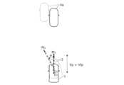
図1は、目標走行経路について説明するための図であり、自車両1が走行車線2の中央線2Cに沿って走行する走行シーンの一例を示す。目標走行経路3は、カメラ等による車両前方の走行車線2や周辺車両4等の認識結果に基づいて生成され、自車両1は、生成された目標走行経路3に沿って走行するように制御される。図1の例では、目標走行経路3は、走行車線2を規定する左右の区画線2L,2Rの認識結果に基づいて、走行車線2の中央線2Cに沿って生成される。Figure 1 is a diagram for explaining the target driving route, and shows an example of a driving scene in which the
目標走行経路3は、自車両1の現地点Oから、現時点から所定の予見時間tp(例えば3.1秒程度)先に通過すべき目標通過地点Ptまでの、単位時間Δt(例えば0.1秒)毎の通過地点Pmを時刻順に接続することにより生成される。目標走行経路3は、所定周期で更新される。The
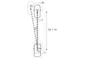
図2Aは、高速走行中に生成される目標走行経路3の変化について説明するための図であり、図2Bは、低速走行中に生成される目標走行経路3の変化について説明するための図である。また、図3Aは、高速走行中に生成される目標走行経路3について説明するための図であり、図3Bは、低速走行中に生成される目標走行経路3について説明するための図である。Figure 2A is a diagram for explaining changes in the
図2A~図3Bに示すように、予見時間tpを一定とすると、自車両1の走行速度(車速)Vに応じて、予見時間tp後の走行位置までの予見距離Xpが変化する。この場合、高速ほど目標通過地点Ptを遠方に設定することで車速Vに応じた適切な目標走行経路3を生成できるが、渋滞等で車速Vが著しく低下した場合には、目標通過地点Ptが現地点Oに近付き過ぎ、適切な目標走行経路3を生成することが難しくなる。As shown in Figures 2A to 3B, if the preview time tp is constant, the preview distance Xp to the driving position after the preview time tp changes depending on the driving speed (vehicle speed) V of the
図2Aおよび図2Bの例では、走行車線2において自車両1の前方を走行する先行車両4aの認識結果に基づいて、先行車両4aに追従するように目標走行経路3が生成される。この場合、自車両1が追従すべき先行車両4aが車幅方向に移動し、目標通過地点Ptが車幅方向に移動すると(Pt1→Pt2)、目標走行経路3が変化して更新され、更新後の目標走行経路3に沿って自車両1が旋回するように制御される。2A and 2B, based on the recognition result of the preceding
特に、図2Bに示すように、自車両1が極低速(例えば10km/h未満)の場合は、予見距離Xpが極短くなり、目標通過地点Ptの移動量に対して必要となる進行方向の変動(旋回角θ)が極めて大きくなる。このような不都合は、図1に示すように自車両1が走行車線2の中央線2Cに沿って走行する走行シーンにおいて、左右の区画線2L,2Rが円滑でない場合等にも生じ得る。In particular, as shown in FIG. 2B, when the
図3Aおよび図3Bの例では、渋滞中の自車両1と先行車両4aとの間で追い越しや割り込み、すり抜け等を行うために自車両1の進路に近付いた並走車両4bが認識されている。この場合、図3Aに示すように、予見距離Xp以内の範囲で並走車両4bが認識されると、乗員の不安感を軽減するため、認識結果に基づいて並走車両4bから離れる方向にオフセットした目標走行経路3が生成される。一方、図3Bに示すように、予見距離Xpを超えた範囲で並走車両4bが認識された場合は、自車両1の進路に近付いた並走車両4bを考慮した目標走行経路3を生成することができない。In the examples of Figures 3A and 3B, a
そこで、本実施形態では、車速Vに応じて適切な予見距離Xpを設定することで、低車速でも適切な目標走行経路3を生成することができるよう、以下のように経路生成装置を構成する。Therefore, in this embodiment, the route generation device is configured as follows so that an appropriate
図4は、本発明の実施形態に係る経路生成装置(以下、装置)100の要部構成および処理の流れの一例を概略的に示すブロック図である。図4に示すように、装置100は、主に電子制御ユニット(ECU)10により構成される。ECU10は、CPU等の演算部、RAM,ROM等の記憶部、I/Oインタフェース、その他の周辺回路を有するコンピュータを含んで構成される。ECU10は、例えば自車両1に搭載されて自車両1の動作を制御する複数のECU群の一部として構成される。図4の処理は、例えば自車両1が始動してECU10が起動されると開始され、所定周期で繰り返される。Figure 4 is a block diagram showing an example of the main configuration and processing flow of a route generation device (hereinafter, device) 100 according to an embodiment of the present invention. As shown in Figure 4, the
ECU10には、自車両1に搭載された走行用アクチュエータ5と、車速センサ6と、外部センサ7とが接続される。走行用アクチュエータ5には、自車両1を転舵させるステアリングギアなどの転舵機構が含まれる。車速センサ6は、例えば車輪の回転速度を検出する車輪速センサにより構成され、車速Vを検出する。The ECU 10 is connected to a driving actuator 5 mounted on the
外部センサ7は、自車両1の進行方向を中心とする車両前方の外部状況を検出する。外部センサ7は、CCDやCMOS等の撮像素子を有し、自車両1の前方を撮像するカメラ8と、自車両1から先行車両4aまでの車間距離を検出する距離検出部9とを含む。距離検出部9は、例えば、ミリ波(電波)を照射し、照射波が物体に当たって戻ってくるまでの時間から、その物体までの距離や方向を測定するミリ波レーダにより構成される。距離検出部9は、レーザ光を照射し、照射光が物体に当たって戻ってくるまでの時間から、その物体までの距離や方向を測定するライダ(LiDAR)により構成されてもよい。The external sensor 7 detects the external situation in front of the
ECU10は、演算部の機能的構成として、前方認識部11と、曲率半径算出部12と、通過地点設定部13と、経路生成部14と、走行制御部15とを有する。すなわち、ECU10の演算部は、前方認識部11と、曲率半径算出部12と、通過地点設定部13と、経路生成部14と、走行制御部15として機能する。The ECU 10 has, as the functional configuration of the calculation unit, a
前方認識部11は、外部センサ7からの信号に基づいて、自車両1の進行方向を中心とする車両前方の道路上の区画線、縁石、ガードレール等の位置を認識することで、自車両1が走行する走行車線2を認識する。また、自車両1の進行方向を中心とする車両前方の道路上の周辺車両4の位置も認識する。一般的な道路形状は、曲率が一定の割合で変化するクロソイド曲線を用いて設計されており、道路形状に対応するクロソイド曲線の一部の区間は、3次関数等の高次関数を用いて近似することができる。The
図5は、前方認識部11による認識結果に基づいて導出される、走行車線2の中央線2Cを表す3次関数F(X)について説明するための図である。図5に示すように、前方認識部11による認識結果に基づいて走行車線2に対する自車両1の進行方向を特定し、自車両1の現地点Oを原点、特定された進行方向をX軸として、走行車線2の中央線2Cを表す3次関数F(X)を導出することができる。すなわち、最小二乗法等のカーブフィッティング手法を用いて、前方認識部11により認識された左右の区画線(あるいは縁石、ガードレール等)2L,2Rを近似する下式(i),(ii)の3次関数FL(X),FR(X)を導出する。
FL(X)=C3LX3+C2LX2+C1LX+C0L ・・・(i)
FR(X)=C3RX3+C2RX2+C1RX+C0R ・・・(ii) 5 is a diagram for explaining a cubic function F(X) representing the
FL (X) = C3L X3 + C2L X2 + C1L X + C0L ... (i)
FR (X) = C3 R X3 + C2 R X2 + C1 R X + C0 R ... (ii)
次いで、左右の区画線2L,2Rに対応する3次関数FL(X),FR(X)に基づいて、走行車線2の中央線2Cに対応する下式(iii)の3次関数F(X)を導出する。
F(X)=C3X3+C2X2+C1X+C0 ・・・(iii)
C3=(C3L+C3R)/2,C2=(C2L+C2R)/2,
C1=(C1L+C1R)/2,C0=(C0L+C0R)/2 Next, based on the cubic functions FL (X) and FR (X) corresponding to the left and
F(X) =C3X3+C2X2 +C1X +C0... (iii)
C3 = (C3L +C3R ) / 2,C2 = (C2L +C2R ) / 2,
C1 = (C1L +C1R ) / 2,C0 = (C0L +C0R ) / 2
曲率半径算出部12は、自車両1が走行する走行車線2の曲率半径Rを算出する。例えば、下式(iv)により予見距離Xp先の走行位置における走行車線2の中央線2Cの曲率半径Rを算出する。
R={1+(3C3Xp2+2C2Xp+C1)2}1.5/(6C3Xp+2C2)・・・(iv) The curvature
R = {1 + (3C3Xp2 + 2C2Xp+C1 )2 }1.5/ (6C3Xp +2C2 )... (iv)
通過地点設定部13は、車速センサ6により検出された車速Vに基づいて予見距離Xpを設定するとともに、現地点Oから予見距離Xp先に目標通過地点Ptを設定する。図6は、通過地点設定部13による目標通過地点Ptの設定について説明するための図であり、目標通過地点Ptを設定するときの予見距離Xpの設定について説明するための図である。The passing
図6に示すように、通過地点設定部13は、車速センサ6により検出された車速Vが所定値V0(例えば11.6km/h程度)以上のとき、予め定められた予見時間tp後の走行位置までの距離を予見距離Xpとして設定する(下式(v))。一方、通過地点設定部13は、車速センサ6により検出された車速Vが所定値V0未満のとき、所定距離X0(例えば10m程度)を予見距離Xpとして設定する(下式(vi))。
Xp=Vtp (V≧V0) ・・・(v)
Xp=X0 (V<V0) ・・・(vi) 6, when the vehicle speed V detected by the vehicle speed sensor 6 is equal to or greater than a predetermined value V0 (e.g., about 11.6 km/h), the passing
Xp = Vtp (V ≥ V0) ... (v)
Xp=X0 (V<V0) ...(vi)
所定距離X0は、渋滞中の平均的な車間距離に設定され、例えば、平均的な車両の全長(例えば5m程度)の2倍程度に設定される。通過地点設定部13は、距離検出部9により検出された自車両1から先行車両4aまでの実際の車間距離を所定距離X0として設定してもよい。The predetermined distance X0 is set to the average inter-vehicle distance during a traffic jam, for example, about twice the overall length of an average vehicle (for example, about 5 m). The passing
経路生成部14は、現地点Oから通過地点設定部13により設定された目標通過地点Ptまでの目標走行経路3を生成する。例えば、前方認識部11による認識結果に基づいて導出された3次関数F(X)で表される走行車線2の中央線2Cに沿って、現地点Oから目標通過地点Ptまでの目標走行経路3を生成する。また、予見距離Xp以内の範囲で自車両1の進路に近付いた並走車両4bが認識されると、認識結果に基づいて並走車両4bから離れる方向にオフセットした目標走行経路3を生成する。The
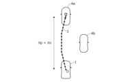
図7は、低速走行中に経路生成部14により生成される目標走行経路3の変化について説明するための図である。図2Bの場合と異なり、低車速でも所定距離X0の予見距離Xpが確保されるため、目標通過地点Pt1,Pt2に至る目標走行経路3の変化に伴う進行方向の変動(旋回角θ)を抑制して、適切な目標走行経路3を生成することができる。Figure 7 is a diagram for explaining changes in the
図8は、低速走行中に経路生成部14により生成される目標走行経路3について説明するための図である。図3Bの場合と異なり、低車速でも所定距離X0の予見距離Xpが確保されるため、自車両1から所定距離X0以内の範囲において自車両1を追い越す並走車両4b等の認識結果を考慮して、適切な目標走行経路3を生成することができる。Figure 8 is a diagram for explaining the
図9Aは、緩やかなカーブ路を走行中に生成される目標走行経路3について説明するための図であり、図9Bは、急なカーブ路を走行中に生成される目標走行経路3について説明するための図である。図9Aに示すように、曲率半径Rが大きい緩やかなカーブ路や直線路では、先が見通しやすく、車速Vに応じて設定された予見距離Xp先の走行位置における走行車線2を精度よく認識し、適切な目標通過地点Ptを設定することができる。一方、図9Bに示すように、曲率半径Rが小さい急なカーブ路では、先が見通しにくく、車速Vに応じて設定された予見距離Xp先の走行位置における走行車線2を精度よく認識できない可能性があり、適切な目標通過地点Ptを設定できない可能性がある。Figure 9A is a diagram for explaining a
そこで、通過地点設定部13は、車速センサ6により検出された車速Vに加えて、さらに曲率半径算出部12により算出された曲率半径Rに基づいて、予見距離Xpを設定するとともに、目標通過地点Ptを設定する。より具体的には、ECU10の記憶部に予め記憶された特性を参照し、車速センサ6により検出された車速Vと、曲率半径算出部12により算出された曲率半径Rとに基づいて、目標通過地点Ptを設定するときの予見距離Xpを設定する。Therefore, the passing
この場合、同一車速における予見距離Xpは、曲率半径Rに応じて走行車線2を精度よく認識できる範囲に設定され、例えば、曲率半径R=100mでは予見距離Xp=50m、曲率半径R=2000mでは予見距離Xp=150mに設定される。目標通過地点Ptまでの予見距離Xpを、曲率半径Rに応じて走行車線2を精度よく認識できる範囲に設定することで、適切な目標走行経路3を生成することができる。In this case, the foreseeing distance Xp at the same vehicle speed is set to a range in which the
走行制御部15は、経路生成部14により生成された目標走行経路3に基づいて、自車両1の運転者に対する運転支援を行うないし自車両1を自動運転するように走行用アクチュエータ5を制御する。これにより、低車速でも適切な目標走行経路3に沿って自車両1を走行させることができる。The driving
本実施形態によれば以下のような作用効果を奏することができる。
(1)装置100は、自車両1の走行時における走行車線2上の目標通過地点Ptを設定する通過地点設定部13と、現地点Oから通過地点設定部13により設定された目標通過地点Ptまでの目標走行経路3を生成する経路生成部14と、自車両1の速度情報を取得する車速センサ6とを備える(図4)。通過地点設定部13は、車速センサ6により取得された速度情報に基づいて、車速Vが所定値V0以上のとき、予見時間tp後の目標通過地点Ptを設定する一方、車速Vが所定値V0未満のとき、現地点Oから所定距離X0先に目標通過地点Ptを設定する(図6)。 According to this embodiment, the following advantageous effects can be obtained.
(1) The
これにより、低車速でも所定距離X0の予見距離Xpが確保されるため、目標通過地点Ptに至る目標走行経路3の変化に伴う進行方向の変動を抑制することができ、適切な目標走行経路3を生成することができる(図2B、図7)。また、自車両1から所定距離X0以内の範囲において自車両1を追い越す並走車両4b等の認識結果を考慮して、適切な目標走行経路3を生成することができる(図3B、図8)。As a result, a foreseeable distance Xp of the predetermined distance X0 is ensured even at low vehicle speeds, so fluctuations in the direction of travel that accompany changes in the
(2)装置100は、自車両1から、自車両1が走行する走行車線2において自車両1の前方を走行する先行車両4aまでの車間距離を検出する距離検出部9をさらに備える(図4)。通過地点設定部13は、距離検出部9により検出された車間距離を所定距離X0に設定する。これにより、渋滞中の自車両1と先行車両4aとの間で追い越しや割り込み、すり抜け等を行う並走車両4bの認識結果を確実に考慮して、適切な目標走行経路3を生成することができる(図3B、図8)。(2) The
(3)装置100は、自車両1が走行する走行車線2の曲率半径Rを算出する曲率半径算出部12をさらに備える(図4)。通過地点設定部13は、さらに曲率半径算出部12により算出された曲率半径Rに基づいて目標通過地点Ptを設定する。すなわち、目標通過地点Ptまでの予見距離Xpを、曲率半径Rに応じて走行車線2を精度よく認識できる範囲に設定することで、適切な目標走行経路3を生成することができる。(3) The
(4)装置100は、自車両1の運転者に対する運転支援を行うないし自車両1を自動運転するように走行用アクチュエータ5を制御する走行制御部15をさらに備える(図4)。走行制御部15は、経路生成部14により生成された目標走行経路3に基づいて、走行用アクチュエータ5を制御する。これにより、低車速でも適切な目標走行経路3に沿って自車両1を走行させることができる。(4) The
上記実施形態では、車輪速センサ等の車速センサ6により車速Vを検出する例を説明したが、自車両の速度情報を取得する速度情報取得部は、このようなものに限らない。例えば、測位衛星からの測位信号に基づいて車両位置を測定し、車両位置の経時変化に基づいて車速を算出するものであってもよい。In the above embodiment, an example was described in which the vehicle speed V was detected by a vehicle speed sensor 6 such as a wheel speed sensor, but the speed information acquisition unit that acquires the speed information of the vehicle is not limited to this. For example, the vehicle position may be measured based on a positioning signal from a positioning satellite, and the vehicle speed may be calculated based on changes in the vehicle position over time.
上記実施形態では、装置100が走行制御部15を備える例を説明したが、経路生成装置は、このようなものに限らない。例えば、経路生成部14により生成された目標走行経路3を車両前方の道路に重畳して表示するようにヘッドアップディスプレイ等の表示部を制御する表示制御部を備えるものでもよい。In the above embodiment, an example was described in which the
上記実施形態では、ミリ波レーダやライダ等の距離検出部9を用いて自車両1から先行車両4aまでの車間距離を検出する例を説明したが、カメラ8により撮像された車両前方の画像データに基づいて自車両1から先行車両4aまでの車間距離を検出してもよい。この場合、カメラ8のみで外部センサ7を構成してもよい。In the above embodiment, an example was described in which the distance between the
以上の説明はあくまで一例であり、本発明の特徴を損なわない限り、上述した実施形態および変形例により本発明が限定されるものではない。上記実施形態と変形例の1つまたは複数を任意に組み合わせることも可能であり、変形例同士を組み合わせることも可能である。The above description is merely an example, and the present invention is not limited to the above-mentioned embodiment and modifications, as long as the characteristics of the present invention are not impaired. It is also possible to arbitrarily combine one or more of the above-mentioned embodiment and modifications, and it is also possible to combine modifications together.
1 自車両、2 走行車線、3 目標走行経路、4 周辺車両、4a 先行車両、4b 並走車両、5 走行用アクチュエータ、6 車速センサ、7 外部センサ、8 カメラ、9 距離検出部、10 電子制御ユニット(ECU)、11 前方認識部、12 曲率半径算出部、13 通過地点設定部、14 経路生成部、15 走行制御部、100 経路生成装置(装置)1 Vehicle, 2 Travel lane, 3 Target travel route, 4 Surrounding vehicles, 4a Leading vehicle, 4b Parallel vehicle, 5 Travel actuator, 6 Vehicle speed sensor, 7 External sensor, 8 Camera, 9 Distance detection unit, 10 Electronic control unit (ECU), 11 Forward recognition unit, 12 Curvature radius calculation unit, 13 Passing point setting unit, 14 Route generation unit, 15 Travel control unit, 100 Route generation device (device)
Claims (4)
Translated fromJapanese前記検出部により検出された物体のうち、自車両が走行する走行車線を認識する前方認識部と、
自車両の走行時における前記走行車線上の目標通過地点を設定する通過地点設定部と、
前記前方認識部により認識された前記走行車線に基づいて前記走行車線に対する自車両の進行方向を特定し、自車両の現地点を原点、前記進行方向をX軸とする座標平面上の、前記現地点と前記目標通過地点とを通る関数を、前記現地点から前記目標通過地点までの目標走行経路として生成する経路生成部と、
自車両の速度情報を取得する速度情報取得部と、を備え、
前記通過地点設定部は、前記速度情報取得部により取得された前記速度情報に基づいて、自車両の走行速度が所定値以上のとき、前記進行方向における前記現地点から前記目標通過地点までの距離であるX軸座標が前記走行速度と所定時間との積となるように前記目標通過地点を設定する一方、前記走行速度が前記所定値未満のとき、前記X軸座標が所定距離となるように前記目標通過地点を設定することを特徴とする経路生成装置。A detection unit that detects an object in a forward area of the host vehicle;
a forward recognition unit that recognizes, among the objects detected by the detection unit, a driving lane in which the host vehicle is traveling;
a passing point setting unit that sets atarget passing point on the driving lane when the host vehicle is traveling;
a route generation unit that identifies a traveling direction of the host vehicle with respect to the traveling lane based on the traveling lane recognized by the forward recognition unit, and generates a function that passes through the current point and the target passing point on a coordinate plane with the current point of the host vehicle as an origin and the traveling direction as an X-axis,as a target traveling route from the current point to thetarget passing point;
A speed information acquisition unit that acquires speed information of the host vehicle,
the passing point setting unit sets the target passing point such that anX -axis coordinate, which is a distancefrom the current point in the traveling direction to the target passing point, is the product of the traveling speed and a predetermined time, whenthe traveling speed of the host vehicleis equal to or greaterthan a predetermined value, based on the speed information acquired by the speed information acquisition unit, and sets thetarget passing point suchthatthe X-axis coordinate is the predetermined distance, when the traveling speed is less thanthe predetermined value.
自車両から、自車両が走行する前記走行車線において自車両の前方を走行する先行車両までの車間距離を検出する距離検出部をさらに備え、
前記通過地点設定部は、前記距離検出部により検出された前記車間距離を前記所定距離に設定することを特徴とする経路生成装置。 The route generating device according to claim 1 ,
A distance detection unit detects a distance from the host vehicle to a preceding vehicle traveling ahead of the host vehicle in thetraveling lane in which the host vehicle is traveling,
The route generation device, whereinthe passing point setting unit sets theinter- vehicle distance detected by the distance detection unit to the predetermined distance.
自車両が走行する前記走行車線の曲率半径を算出する曲率半径算出部をさらに備え、
前記通過地点設定部は、さらに前記曲率半径算出部により算出された前記曲率半径に基づいて前記目標通過地点を設定することを特徴とする経路生成装置。 3. The route generating device according to claim 1,
A curvature radius calculation unit is further provided for calculating a curvature radius of the driving laneon which the vehicle is traveling,
The route generation device, whereinthe passing point setting unit further sets the target passing point based onthe radius of curvature calculated by the radius of curvature calculation unit.
自車両の運転者に対する運転支援を行うないし自車両を自動運転するように走行用アクチュエータを制御する走行制御部をさらに備え、
前記走行制御部は、前記経路生成部により生成された前記目標走行経路に基づいて、前記走行用アクチュエータを制御することを特徴とする経路生成装置。 In the path generation device according to any one of claims 1 to 3,
A driving control unit that provides driving assistance to a driver of the vehicle or controls a driving actuator to automatically drive the vehicle,
The route generation device, wherein the travel control unit controls the travel actuators based onthe target travel route generated by the route generation unit.
Priority Applications (3)
| Application Number | Priority Date | Filing Date | Title |
|---|---|---|---|
| JP2022008735AJP7510446B2 (en) | 2022-01-24 | 2022-01-24 | Route Generation Device |
| CN202310013696.0ACN116486637A (en) | 2022-01-24 | 2023-01-05 | Path generation device and path generation method |
| US18/098,692US12246710B2 (en) | 2022-01-24 | 2023-01-18 | Path generation apparatus and path generation method |
Applications Claiming Priority (1)
| Application Number | Priority Date | Filing Date | Title |
|---|---|---|---|
| JP2022008735AJP7510446B2 (en) | 2022-01-24 | 2022-01-24 | Route Generation Device |
Publications (2)
| Publication Number | Publication Date |
|---|---|
| JP2023107500A JP2023107500A (en) | 2023-08-03 |
| JP7510446B2true JP7510446B2 (en) | 2024-07-03 |
Family
ID=87210767
Family Applications (1)
| Application Number | Title | Priority Date | Filing Date |
|---|---|---|---|
| JP2022008735AActiveJP7510446B2 (en) | 2022-01-24 | 2022-01-24 | Route Generation Device |
Country Status (3)
| Country | Link |
|---|---|
| US (1) | US12246710B2 (en) |
| JP (1) | JP7510446B2 (en) |
| CN (1) | CN116486637A (en) |
Families Citing this family (1)
| Publication number | Priority date | Publication date | Assignee | Title |
|---|---|---|---|---|
| JP7510446B2 (en)* | 2022-01-24 | 2024-07-03 | 本田技研工業株式会社 | Route Generation Device |
Citations (4)
| Publication number | Priority date | Publication date | Assignee | Title |
|---|---|---|---|---|
| JP2007091025A (en) | 2005-09-28 | 2007-04-12 | Fuji Heavy Ind Ltd | Vehicle front monitoring device |
| JP2017165156A (en) | 2016-03-14 | 2017-09-21 | 本田技研工業株式会社 | Vehicle control system, vehicle control method and vehicle control program |
| JP2018181209A (en) | 2017-04-20 | 2018-11-15 | マツダ株式会社 | Driving support device for vehicle |
| US20180354513A1 (en) | 2017-06-13 | 2018-12-13 | GM Global Technology Operations LLC | System And Method For Low Speed Lateral Control Of A Vehicle |
Family Cites Families (21)
| Publication number | Priority date | Publication date | Assignee | Title |
|---|---|---|---|---|
| DE4313568C1 (en)* | 1993-04-26 | 1994-06-16 | Daimler Benz Ag | Guiding motor vehicle driver when changing traffic lanes - using radar devices to detect velocity and spacing of vehicles in next lane and indicate when lane changing is possible |
| JP3732292B2 (en)* | 1996-11-27 | 2006-01-05 | 本田技研工業株式会社 | Vehicle group running control system |
| US7016783B2 (en)* | 2003-03-28 | 2006-03-21 | Delphi Technologies, Inc. | Collision avoidance with active steering and braking |
| US8428843B2 (en)* | 2008-06-20 | 2013-04-23 | GM Global Technology Operations LLC | Method to adaptively control vehicle operation using an autonomic vehicle control system |
| KR101276871B1 (en)* | 2009-12-14 | 2013-06-18 | 안동대학교 산학협력단 | Method and apparatus for collision avoidance of vehicle |
| US9499197B2 (en)* | 2014-10-15 | 2016-11-22 | Hua-Chuang Automobile Information Technical Center Co., Ltd. | System and method for vehicle steering control |
| JP6315107B2 (en)* | 2015-01-05 | 2018-04-25 | 日産自動車株式会社 | Target route generation device and travel control device |
| JP6115576B2 (en)* | 2015-01-07 | 2017-04-19 | トヨタ自動車株式会社 | Vehicle travel control device |
| US9868443B2 (en)* | 2015-04-27 | 2018-01-16 | GM Global Technology Operations LLC | Reactive path planning for autonomous driving |
| JP6380766B2 (en)* | 2016-03-14 | 2018-08-29 | 本田技研工業株式会社 | Vehicle control device, vehicle control method, and vehicle control program |
| JP6579119B2 (en)* | 2017-01-24 | 2019-09-25 | トヨタ自動車株式会社 | Vehicle control device |
| JP6464499B2 (en)* | 2017-06-02 | 2019-02-06 | 本田技研工業株式会社 | Vehicle control device, vehicle control method, and program |
| JP6528336B2 (en)* | 2017-06-02 | 2019-06-12 | 本田技研工業株式会社 | Vehicle control system and vehicle control method |
| JP6460425B2 (en)* | 2017-06-02 | 2019-01-30 | 本田技研工業株式会社 | Vehicle control system, vehicle control method, and program |
| JP6630713B2 (en) | 2017-11-02 | 2020-01-15 | 本田技研工業株式会社 | Vehicle shift control device |
| JP7069518B2 (en)* | 2018-01-17 | 2022-05-18 | マツダ株式会社 | Vehicle control unit |
| WO2020044904A1 (en)* | 2018-08-28 | 2020-03-05 | 日立オートモティブシステムズ株式会社 | Travel control device and travel control method |
| EP3971862B1 (en)* | 2019-05-15 | 2023-02-15 | NISSAN MOTOR Co., Ltd. | Traveling control method and traveling control device for vehicle |
| JP7303667B2 (en)* | 2019-05-31 | 2023-07-05 | 株式会社Subaru | Automated driving support device |
| JP7183237B2 (en)* | 2020-10-23 | 2022-12-05 | 本田技研工業株式会社 | VEHICLE CONTROL DEVICE, VEHICLE CONTROL METHOD, AND PROGRAM |
| JP7510446B2 (en)* | 2022-01-24 | 2024-07-03 | 本田技研工業株式会社 | Route Generation Device |
- 2022
- 2022-01-24JPJP2022008735Apatent/JP7510446B2/enactiveActive
- 2023
- 2023-01-05CNCN202310013696.0Apatent/CN116486637A/enactivePending
- 2023-01-18USUS18/098,692patent/US12246710B2/enactiveActive
Patent Citations (4)
| Publication number | Priority date | Publication date | Assignee | Title |
|---|---|---|---|---|
| JP2007091025A (en) | 2005-09-28 | 2007-04-12 | Fuji Heavy Ind Ltd | Vehicle front monitoring device |
| JP2017165156A (en) | 2016-03-14 | 2017-09-21 | 本田技研工業株式会社 | Vehicle control system, vehicle control method and vehicle control program |
| JP2018181209A (en) | 2017-04-20 | 2018-11-15 | マツダ株式会社 | Driving support device for vehicle |
| US20180354513A1 (en) | 2017-06-13 | 2018-12-13 | GM Global Technology Operations LLC | System And Method For Low Speed Lateral Control Of A Vehicle |
Also Published As
| Publication number | Publication date |
|---|---|
| US12246710B2 (en) | 2025-03-11 |
| US20230234582A1 (en) | 2023-07-27 |
| JP2023107500A (en) | 2023-08-03 |
| CN116486637A (en) | 2023-07-25 |
Similar Documents
| Publication | Publication Date | Title |
|---|---|---|
| US10864911B2 (en) | Automated detection of hazardous drifting vehicles by vehicle sensors | |
| US11433889B2 (en) | Driving control apparatus for vehicle | |
| EP3678113B1 (en) | Travel control method and travel control device for driving-assist vehicle | |
| JP7481296B2 (en) | Vehicle driving control device | |
| KR102553247B1 (en) | Lane keep assist system and method for improving safety in forward vehicle follower longitudinal control | |
| US10513267B2 (en) | Vehicle safety system | |
| US10766491B2 (en) | Driving change control device and driving change control method | |
| US9802613B2 (en) | Driver assistance system for motor vehicles | |
| US11260859B2 (en) | Vehicle control system, vehicle control method, and storage medium | |
| US7634339B2 (en) | Vehicle drive assist device | |
| US20180046191A1 (en) | Control system and control method for determining a trajectory and for generating associated signals or control commands | |
| US20180043886A1 (en) | Control system and control method for guiding a motor vehicle along a path and for avoiding a collision with another motor vehicle | |
| US10967864B2 (en) | Vehicle control device | |
| CN107200012A (en) | The travel controlling system of vehicle | |
| US10457327B2 (en) | Method and system of assisting a driver of a vehicle | |
| JP4232806B2 (en) | Vehicle control device | |
| JP7510446B2 (en) | Route Generation Device | |
| JP7240649B2 (en) | Vehicle travel control device | |
| JP2005182186A (en) | Vehicle trajectory setting device | |
| JP7499797B2 (en) | Route Generation Device | |
| CN114523968B (en) | Surrounding vehicle monitoring device and surrounding vehicle monitoring method | |
| US20210166090A1 (en) | Driving assistance for the longitudinal and/or lateral control of a motor vehicle | |
| JP7458428B2 (en) | route generation device | |
| US20250214579A1 (en) | Vehicle control device, vehicle control method, and storage medium | |
| WO2023149003A1 (en) | Vehicle control device |
Legal Events
| Date | Code | Title | Description |
|---|---|---|---|
| A621 | Written request for application examination | Free format text:JAPANESE INTERMEDIATE CODE: A621 Effective date:20220928 | |
| A131 | Notification of reasons for refusal | Free format text:JAPANESE INTERMEDIATE CODE: A131 Effective date:20231205 | |
| A521 | Request for written amendment filed | Free format text:JAPANESE INTERMEDIATE CODE: A523 Effective date:20240201 | |
| TRDD | Decision of grant or rejection written | ||
| A01 | Written decision to grant a patent or to grant a registration (utility model) | Free format text:JAPANESE INTERMEDIATE CODE: A01 Effective date:20240604 | |
| A61 | First payment of annual fees (during grant procedure) | Free format text:JAPANESE INTERMEDIATE CODE: A61 Effective date:20240621 | |
| R150 | Certificate of patent or registration of utility model | Ref document number:7510446 Country of ref document:JP Free format text:JAPANESE INTERMEDIATE CODE: R150 |