JP7508404B2 - Ultrasonic Drying Equipment - Google Patents
Ultrasonic Drying EquipmentDownload PDFInfo
- Publication number
- JP7508404B2 JP7508404B2JP2021067975AJP2021067975AJP7508404B2JP 7508404 B2JP7508404 B2JP 7508404B2JP 2021067975 AJP2021067975 AJP 2021067975AJP 2021067975 AJP2021067975 AJP 2021067975AJP 7508404 B2JP7508404 B2JP 7508404B2
- Authority
- JP
- Japan
- Prior art keywords
- ultrasonic
- dried
- element array
- ultrasonic waves
- ultrasonic element
- Prior art date
- Legal status (The legal status is an assumption and is not a legal conclusion. Google has not performed a legal analysis and makes no representation as to the accuracy of the status listed.)
- Active
Links
- 238000001035dryingMethods0.000titleclaimsdescription86
- 238000003780insertionMethods0.000claimsdescription12
- 230000037431insertionEffects0.000claimsdescription12
- 238000001514detection methodMethods0.000claimsdescription4
- 230000001678irradiating effectEffects0.000claimsdescription4
- 238000003491arrayMethods0.000description21
- 239000013256coordination polymerSubstances0.000description21
- 230000005855radiationEffects0.000description21
- 238000002604ultrasonographyMethods0.000description21
- 238000010586diagramMethods0.000description11
- 230000007423decreaseEffects0.000description7
- 238000005516engineering processMethods0.000description6
- XLYOFNOQVPJJNP-UHFFFAOYSA-NwaterSubstancesOXLYOFNOQVPJJNP-UHFFFAOYSA-N0.000description5
- 244000052616bacterial pathogenSpecies0.000description4
- 238000007664blowingMethods0.000description2
- 238000000034methodMethods0.000description2
- 238000013459approachMethods0.000description1
- 230000003111delayed effectEffects0.000description1
- 230000001066destructive effectEffects0.000description1
- 230000005484gravityEffects0.000description1
- 238000005511kinetic theoryMethods0.000description1
- 230000003014reinforcing effectEffects0.000description1
- 239000007787solidSubstances0.000description1
- 230000009466transformationEffects0.000description1
- 230000001131transforming effectEffects0.000description1
Images


Landscapes
- Drying Of Solid Materials (AREA)
- Transducers For Ultrasonic Waves (AREA)
Description
Translated fromJapanese本発明は、乾燥対象物に超音波を照射することによって、乾燥対象物を乾燥させる超音波乾燥装置に関する。The present invention relates to an ultrasonic drying device that dries an object to be dried by irradiating the object with ultrasonic waves.
手に付着した水分を高圧の空気で吹き飛ばすことによって、手を乾燥させる乾燥装置が知られている(特許文献1)。また、高圧の空気を吹き付ける代わりに、超音波を手に照射して、超音波で水分を霧化させることによって、手を乾燥させる乾燥装置も提案されている(特許文献2)。A drying device that dries hands by blowing away moisture on the hands with high-pressure air is known (Patent Document 1). In addition, a drying device has been proposed that dries hands by irradiating the hands with ultrasound instead of blowing high-pressure air, and using the ultrasound to atomize the moisture (Patent Document 2).
これらの技術を用いれば、濡れた手をタオルなどで拭うことなく、迅速に乾燥させることが可能である。また、手以外の乾燥対象物(例えば食器など)に対してこれらの技術を適用すれば、様々な乾燥対象物を迅速に乾燥させることが可能と考えられる。Using these technologies, it is possible to quickly dry wet hands without having to wipe them with a towel or the like. Furthermore, if these technologies are applied to objects other than hands (such as tableware), it is thought that it may be possible to quickly dry a variety of objects.
しかし、提案されている技術では、手や食器などの乾燥対象物を乾燥させる際に、乾燥対象物に付着した水分を周囲に拡散させてしまう可能性があり、特に、水分中に雑菌が含まれていた場合には雑菌も周囲に拡散させてしまう可能性があるという問題がある。例えば、高圧の空気で水分を吹き飛ばす技術では、水分と一緒に雑菌も周囲に吹き飛ばしてしまう可能性があり、また、超音波で水分を霧化する技術では、霧化した水分と一緒に雑菌も周囲に拡散してしまう可能性がある。However, the proposed technology has the problem that when drying objects such as hands or dishes, moisture adhering to the object may be dispersed to the surroundings, and in particular, if the moisture contains germs, the germs may be dispersed to the surroundings. For example, a technology that blows away moisture with high pressure air may blow germs to the surroundings along with the moisture, and a technology that atomizes moisture with ultrasound may spread germs to the surroundings along with the atomized moisture.
この発明は、従来の技術が有する上述した課題を解決するために成されたものであり、乾燥対象物に付着している水分を周囲に拡散させることなく、迅速に乾燥させることが可能な超音波乾燥装置を提供することを目的とする。This invention was made to solve the above-mentioned problems of the conventional technology, and aims to provide an ultrasonic drying device that can quickly dry the object to be dried without diffusing the moisture adhering to the object to be dried into the surroundings.
上述した課題を解決するために、本発明の超音波乾燥装置は次の構成を採用した。すなわち、
乾燥室の開口部から前記乾燥室内に挿入された乾燥対象物に対して超音波を照射することによって、前記乾燥対象物を乾燥させる超音波乾燥装置において、
前記開口部から前記乾燥対象物が挿入される挿入方向に対して側方に存在する前記乾燥室の内壁面上に配列された複数の超音波素子と、
前記複数の超音波素子を駆動することによって、前記乾燥室内に向けて前記超音波を放出させる超音波素子駆動部と
を備え、
前記超音波素子駆動部は、前記複数の超音波素子から前記超音波を放出させると共に、前記複数の超音波素子の間での前記超音波の位相差を制御することによって、前記複数の超音波素子から放出される前記超音波を用いて、前記乾燥対象物上で互いに強め合う干渉を生じさせる
ことを特徴とする。 In order to solve the above-mentioned problems, the ultrasonic drying device of the present invention adopts the following configuration.
1. An ultrasonic drying device for drying an object to be dried by irradiating ultrasonic waves onto the object to be dried inserted into a drying chamber through an opening of the drying chamber,
A plurality of ultrasonic elements are arranged on an inner wall surface of the drying chamber that is located to the side with respect to an insertion direction in which the object to be dried is inserted through the opening;
an ultrasonic element driving unit that drives the plurality of ultrasonic elements to emit the ultrasonic waves toward the drying chamber,
The ultrasonic element driving unit emits ultrasonic waves from the multiple ultrasonic elements and controls a phase difference of the ultrasonic waves among the multiple ultrasonic elements, thereby using the ultrasonic waves emitted from the multiple ultrasonic elements to generate constructive interference on the object to be dried.
かかる本発明の超音波乾燥装置においては、乾燥室の内壁面上に複数の超音波素子が搭載されており、超音波素子駆動部を用いて複数の超音波素子を駆動することによって、乾燥室内に挿入された乾燥対象物に対して超音波を照射する。このとき、超音波素子駆動部は、複数の超音波素子の間での超音波の位相差を制御することによって、複数の超音波素子から放出される超音波を用いて、乾燥対象物上で互いに強め合う干渉を生じさせる。In the ultrasonic drying device of the present invention, multiple ultrasonic elements are mounted on the inner wall surface of the drying chamber, and ultrasonic waves are irradiated onto the object to be dried inserted into the drying chamber by driving the multiple ultrasonic elements using an ultrasonic element driving unit. At this time, the ultrasonic element driving unit controls the phase difference of the ultrasonic waves between the multiple ultrasonic elements, thereby using the ultrasonic waves emitted from the multiple ultrasonic elements to generate constructive interference on the object to be dried.
一般に、物体に超音波を照射すると、物体の表面には音響放射圧と呼ばれる圧力が生じることが知られている。従って、複数の超音波素子から放出される超音波を用いて、乾燥対象物上で超音波が互いに強め合う干渉を生じさせると、強め合う干渉が生じる位置では、周囲の位置よりも超音波の強さが増幅されるため、音響放射圧も大きくなる。このため、乾燥対象物上に付着している水分は、音響放射圧の作用によって、強め合う干渉が生じる位置から周囲へと移動することになる。このことから、例えば乾燥対象物を移動させるなどして、乾燥対象物上で超音波が互いに強め合う干渉となる位置を移動させれば、乾燥対象物上に付着している水分を移動させることができる。そして、乾燥対象物上の水分を移動させることによって乾燥対象物上から除去してやれば、乾燥対象物を迅速に乾燥させることができる。また、上述した方法では、乾燥対象物上に付着している水分を移動させているだけで、水分を吹き飛ばしたり霧化させたりしているわけではないので、水分を周囲に拡散させることもない。It is generally known that when ultrasonic waves are irradiated onto an object, a pressure called acoustic radiation pressure is generated on the surface of the object. Therefore, when ultrasonic waves emitted from multiple ultrasonic elements are used to generate constructive interference between the ultrasonic waves on the object to be dried, the strength of the ultrasonic waves is amplified at the position where the constructive interference occurs more than in the surrounding positions, and the acoustic radiation pressure is also large. Therefore, moisture adhering to the object to be dried moves from the position where the constructive interference occurs to the surroundings due to the action of the acoustic radiation pressure. For this reason, if the position where the ultrasonic waves cause constructive interference on the object to be dried is moved, for example by moving the object to be dried, the moisture adhering to the object to be dried can be moved. If the moisture on the object to be dried is removed from the object to be dried by moving it, the object to be dried can be dried quickly. In addition, in the above-mentioned method, the moisture adhering to the object to be dried is only moved, and the moisture is not blown off or atomized, so the moisture is not diffused to the surroundings.
また、上述した本発明の超音波乾燥装置においては、複数の超音波素子から放出される超音波が、乾燥対象物の挿入方向に対して交差する平面上で互いに強め合う干渉となるように、複数の超音波素子の間での超音波の位相差を制御するようにしてもよい。In addition, in the ultrasonic drying device of the present invention described above, the phase difference of the ultrasonic waves between the multiple ultrasonic elements may be controlled so that the ultrasonic waves emitted from the multiple ultrasonic elements are mutually constructively interfered with on a plane intersecting the insertion direction of the object to be dried.
こうすれば、超音波が強め合う干渉となる平面が、乾燥室内に挿入された乾燥対象物を、挿入方向に対して交差する方向に横切る状態となる。そして、強め合う干渉となる平面が乾燥対象物上を横切る帯状の領域では、乾燥対象物上の水分が周囲の領域に移動する。従って、例えば乾燥対象物を移動させるなどして、乾燥対象物上で超音波が互いに強め合う干渉となる位置を移動させれば、乾燥対象物上の帯状の領域で水分を一斉に移動させることができるので、乾燥対象物上の水分を取り残すことなく移動させることができる。その結果、乾燥対象物を迅速に乾燥させることが可能となる。In this way, a plane where ultrasonic waves cause constructive interference crosses the object to be dried inserted into the drying chamber in a direction intersecting the insertion direction. In the band-shaped region where the plane causing constructive interference crosses the object to be dried, moisture on the object to be dried moves to the surrounding region. Therefore, if the position on the object to be dried where ultrasonic waves cause constructive interference is moved, for example by moving the object to be dried, it is possible to move all the moisture in the band-shaped region on the object to be dried at once, so that it is possible to move the moisture on the object to be dried without leaving any behind. As a result, it is possible to dry the object to be dried quickly.
また、上述した本発明の超音波乾燥装置においては、乾燥室内に挿入される乾燥対象物を検知部で検知可能としておき、乾燥対象物が検知されたら、複数の超音波素子を駆動して超音波を放出させるようにしてもよい。In addition, in the ultrasonic drying device of the present invention described above, the object to be dried inserted into the drying chamber can be detected by the detection unit, and when the object to be dried is detected, multiple ultrasonic elements can be driven to emit ultrasonic waves.
こうすれば、乾燥室内に乾燥対象物が挿入されていない場合は超音波が放出されないので、無駄に超音波を放出する事態を回避することが可能となる。In this way, ultrasonic waves are not emitted if no object to be dried is inserted into the drying chamber, making it possible to avoid unnecessary emission of ultrasonic waves.
また、上述した本発明の超音波乾燥装置においては、複数の超音波素子の間での超音波の位相差を変更することによって、複数の超音波素子から放出される超音波が互いに強め合う干渉となる位置が、乾燥対象物の挿入方向に移動するようにしてもよい。In addition, in the ultrasonic drying device of the present invention described above, the phase difference of the ultrasonic waves between the multiple ultrasonic elements may be changed so that the position where the ultrasonic waves emitted from the multiple ultrasonic elements interfere with each other in a reinforcing manner may be moved in the insertion direction of the object to be dried.
こうすれば、乾燥室内に挿入した乾燥対象物を移動させなくても、超音波が互いに強め合う干渉となる位置を移動させることによって、乾燥対象物上の水分を除去することができるので、乾燥対象物を簡単に乾燥させることが可能となる。In this way, the moisture on the object to be dried can be removed by moving the position where the ultrasonic waves interfere with each other in a constructive manner without moving the object inserted in the drying chamber, making it possible to easily dry the object to be dried.
また、上述した本発明の超音波乾燥装置においては、乾燥室の上面に開口部を形成することによって、乾燥対象物が開口部から下方に向けて挿入されるようにしておき、複数の超音波素子が斜め下方に向かって超音波を放出するようにしてもよい。In addition, in the ultrasonic drying device of the present invention described above, an opening may be formed on the upper surface of the drying chamber so that the object to be dried is inserted downward through the opening, and multiple ultrasonic elements emit ultrasonic waves diagonally downward.
こうすれば、超音波は乾燥対象物に対して斜め下向きに照射されることになる。このため、超音波を乾燥対象物に照射したときに、超音波が強め合う干渉となる位置では、乾燥対象物上の水分が重力の方向に移動することになるので、水分を迅速に除去することができる。その結果、乾燥対象物を迅速に乾燥させることが可能となる。In this way, the ultrasonic waves are irradiated diagonally downwards onto the object to be dried. Therefore, when ultrasonic waves are irradiated onto the object to be dried, at positions where the ultrasonic waves interfere constructively, the moisture on the object to be dried moves in the direction of gravity, allowing the moisture to be removed quickly. As a result, the object to be dried can be dried quickly.
また、上述した本発明の超音波乾燥装置においては、乾燥対象物を挿入する挿入方向に対して側方で、且つ、互いに向き合う位置にある複数の内壁面上に、複数の超音波素子を配列することとしてもよい。In addition, in the ultrasonic drying device of the present invention described above, multiple ultrasonic elements may be arranged on multiple inner wall surfaces that are located to the side of the insertion direction in which the object to be dried is inserted and facing each other.
こうすれば、乾燥対象物の両側から超音波を照射することができるので、乾燥対象物の表側および裏側に付着している水分を同時に除去することができる。その結果、乾燥対象物を迅速に乾燥させることが可能となる。In this way, ultrasonic waves can be applied to both sides of the object to be dried, so moisture adhering to the front and back of the object to be dried can be removed simultaneously. As a result, the object to be dried can be dried quickly.
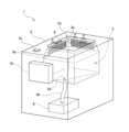
図1は、本実施例の超音波乾燥装置1の大まかな構造を示した斜視図である。図1に示すように、本実施例の超音波乾燥装置1は、直方体形状の本体ケース2の上面に開口部2oが開口し、開口部2oの奥に直方体形状の乾燥室3が形成された構造となっている。開口部2oの形状は正方形または長方形となっており、乾燥室3を水平方向に切断した時の断面形状も正方形または長方形となっているが、乾燥室3の断面形状は開口部2oよりも大きくなっている。このため、乾燥室3の上部は上に行くほど断面が小さくなって開口部2oに繋がる形状となっており、その結果、乾燥室3の上部の内壁面3aは、上端が内側に傾くことによって斜め下方を向いた状態となっている。そして、それらの内壁面3aには、複数の超音波素子4が配置されている。Figure 1 is a perspective view showing the general structure of the
複数の超音波素子4は、図2に示すように、複数の超音波素子4が水平方向に向かって一列に配列されることによって超音波素子アレイ4Lを形成し、その超音波素子アレイ4Lが上下方向の複数段に配置されている。尚、本実施例では、水平方向は、手などの乾燥対象物の挿入方向に対して交差する方向となっている。また、本実施例では、超音波素子アレイ4Lが上下方向の4段に配置されているものとして説明するが、超音波素子アレイ4Lの段数は2段以上であればよく、必ずしも4段でなくてもよい。また、以下では、4段の超音波素子アレイ4Lを区別する必要がある場合には、最上段の超音波素子アレイ4Lを超音波素子アレイ4Laと表記し、上から2段目の超音波素子アレイ4Lを超音波素子アレイ4Lbと表記し、上から3段目の超音波素子アレイ4Lを超音波素子アレイ4Lcと表記し、最下段の超音波素子アレイ4Lを超音波素子アレイ4Ldと表記して区別する。2, the
また、本実施例の超音波乾燥装置1では、4つの内壁面3aの何れにも複数の超音波素子4が配置されているものとしているが、何れか1つの内壁面3aに配置されていてもよい。もっとも、手などの乾燥対象物を迅速に乾燥させるためには、複数の超音波素子4を複数の内壁面3aに配置することが好ましく、特に、向かい合う2つの内壁面3aに配置することが望ましい。In addition, in the
図1に示すように、開口部2oの内側には、正方形または長方形の一辺に相当する位置に投光部6が搭載されている。更に、投光部6が搭載された一辺と向かい合う一辺の位置には、受光部7(図3参照)が搭載されている。投光部6は受光部7に向かって所定波長(例えば赤色)の光を照射しており、受光部7はその所定波長の光を受光したことを検知することができる。このため、開口部2oから乾燥室3内に、手などの乾燥対象物が挿入されると、投光部6から照射された光が受光部7に届かなくなるため、乾燥対象物が挿入されたことを検知することが可能となっている。As shown in FIG. 1, a light-
尚、本実施例の投光部6および受光部7は、本発明における「検知部」に対応する。また、本実施例では、投光部6および受光部7を用いて乾燥対象物を検知しているが、開口部2oから挿入された乾燥対象物を検知することができれば、他の方法を用いて検知してもよい。例えば、投光部6の代わりに赤外線を検出する赤外線センサを搭載しておき、人間が手を開口部2oから挿入した時に、手の温度に応じて放出される赤外線を検出することによって、手が挿入されたことを検知してもよい。あるいは、投光部6の代わりに、超音波パルスを放出すると共に、物体で反射して戻って来た超音波を検出する超音波センサを搭載しておき、超音波パルスを放出してから戻って来たパルスを検出するまでの時間に基づいて、開口部2oに挿入された物体を検知してもよい。また、投光部6の代わりに赤外線センサや超音波センサを搭載する場合は、受光部7は不要となる。The
本体ケース2の内部にはコントローラ10が搭載されている。コントローラ10は複数の超音波素子4に接続されており、それぞれの超音波素子4に駆動信号を出力することによって、各超音波素子4から乾燥室3内に向かって超音波を放出することが可能となっている。尚、本実施例のコントローラ10は、本発明における「超音波素子駆動部」に対応する。A
また、乾燥室3の底面にはドレン穴3dが形成されており、ドレン穴3dからはドレンホース8hを介してドレンタンク8に接続されている。更に、本体ケース2の上面には電源スイッチ2sが搭載されており、ユーザが電源スイッチ2sを押すと、コントローラ10が起動すると共に、投光部6が受光部7に向かって光を照射することによって、超音波乾燥装置1が動作可能な状態となる。A
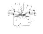
図3は、上述した本実施例の超音波乾燥装置1の動作を示す説明図である。上述したように、超音波乾燥装置1の電源スイッチ2sが押されると、投光部6から受光部7に向かって所定波長の光が照射される。図3では、投光部6から照射される光が破線の矢印によって表されている。その状態で、開口部2oから乾燥室3内に乾燥対象物(図示した例では手)を挿入すると、投光部6からの光を受光部7で検知できなくなる。すると受光部7は、乾燥対象物が挿入されたことを検知して、そのことを示す信号をコントローラ10(図1参照)に出力する。この信号を受けてコントローラ10が、複数の超音波素子4に対して電圧波形が正弦波の駆動信号を出力すると、それぞれの超音波素子4から乾燥室3内に向かって超音波が放出される。Figure 3 is an explanatory diagram showing the operation of the
ここで、コントローラ10は、全ての超音波素子4に対して同じ周波数の駆動信号を出力するが、位相については、超音波素子アレイ4Lの単位で次のような位相に変更する。まず、超音波素子アレイ4Lbと超音波素子アレイ4Lcとについては、周波数だけでなく位相も同じ駆動信号を出力する。しかし、超音波素子アレイ4Laと超音波素子アレイ4Lbとは、後述する所定量だけ位相が異なる駆動信号を出力する。また、超音波素子アレイ4Laと超音波素子アレイ4Ldとは、位相が同じ駆動信号を出力する。このようにして、各超音波素子アレイ4Lの超音波素子4を駆動すると、それぞれの超音波素子4から放射された超音波は、乾燥室3の内部に、強め合う干渉を起こす平面状の領域を形成する。以下では、超音波が強め合う干渉を起こす平面状の領域を、「強干渉領域5」と表記することにする。図3で細かな斜線を付した細長い領域は、強干渉領域5を概念的に表したものである。Here, the
また、超音波を物体に照射すると、物体には音響放射圧と呼ばれる圧力が加わって、物体に一方向の力が作用することが知られている。以下では、音響放射圧によって物体に作用する一方向の力を、「音響放射力」と表記することにする。尚、音波(超音波を含む)は、大気圧を中心とした圧力の正負の変動が移動していく現象であり、物体の表面では圧力が正負に変動するだけである。それにも拘らず、超音波になると音響放射圧によって物体に一方向の力(音響放射力)が発生する理由については後述する。It is also known that when ultrasound is irradiated onto an object, a pressure called acoustic radiation pressure is applied to the object, and a unidirectional force acts on the object. In what follows, the unidirectional force acting on an object due to acoustic radiation pressure will be referred to as "acoustic radiation force." Note that sound waves (including ultrasound) are a phenomenon in which positive and negative fluctuations in pressure move around atmospheric pressure, and on the surface of an object, the pressure simply fluctuates between positive and negative. Nevertheless, the reason why a unidirectional force (acoustic radiation force) is generated on an object due to acoustic radiation pressure when it becomes ultrasound will be explained later.
音響放射力は、超音波が大きく(すなわち、超音波の圧力振幅が大きく)なるほど大きくなる。そして、強干渉領域5では、4つの超音波素子アレイ4Lからの超音波が強め合うから、大きな音響放射力が発生することになる。図3中で強干渉領域5内に表示した白抜きの矢印は、音響放射力を概念的に表している。更に、複数の超音波素子4は斜め下向きに超音波を放出するから、強干渉領域5も斜め下向きの平面となり、強干渉領域5内に生じる音響放射力も斜め下向きの力となる。図3では、図面上で左側の超音波素子アレイ4La~4Ldによって形成される強干渉領域5および音響放射力は右下がりとなっており、右側の超音波素子アレイ4La~4Ldによって形成される強干渉領域5および音響放射力は左下がりとなっている。The acoustic radiation force increases as the ultrasonic waves become larger (i.e., the pressure amplitude of the ultrasonic waves becomes larger). In the
以上のような強干渉領域5が乾燥室3内に形成された状態で、濡れた手を乾燥室3内に挿入すると、手が強干渉領域5に横切っている部分では、手の表面に音響放射力が作用することになる。その状態で、ゆっくりと手を引き上げると、以下の理由から、手に付着した水分を除去することができ、結果として手を迅速に乾燥させることが可能となる。When a wet hand is inserted into the drying
図4は、乾燥室3に挿入された手に強干渉領域5の音響放射力が作用している状態を示した説明図である。上述したように強干渉領域5内では大きな音響放射力が発生しているから、手の表面に付着していた水膜は、音響放射力によって上下方向に押し分けられる。また、音響放射力は、斜め下向きに作用するから、水膜が上方に押し上げられる分量よりも下方に押し下げられる分量の方が多くなる。そして、その状態でゆっくりと手を引き上げて行けば、手の表面に付着していた水膜を下方に押し下げていき、最後には指先から滴下させることができる。こうすれば、手に付着していた水分を除去することができるので、手を迅速に乾燥させることが可能となる。また、滴下した水分は乾燥室3の底面に形成されたドレン穴3dから、ドレンホース8hを通ってドレンタンク8に溜められる。Figure 4 is an explanatory diagram showing the state in which the acoustic radiation force of the
また、超音波は、手などの乾燥対象物で遮られてしまうと乾燥対象物の裏側には届かない。図4に示した例では、超音波素子アレイ4Lからの超音波は手の甲には届くが、手の平側には届かない。そこで、手の平側にも超音波素子アレイ4Lを搭載しておいてもよい。すなわち、前述したように複数の超音波素子4は乾燥室3の内壁面3aに搭載されており、乾燥室3には4つの内壁面3aを有するが(図1参照)、向かい合う内壁面3aに複数の超音波素子4を搭載しておくことが望ましい。こうすれば、手の甲に付着した水分を除去しながら、手の平に付着した水分も同時に除去することができるので、より一層迅速に手を乾燥させることが可能となる。また、図1に例示したように、4つの内壁面3aに超音波素子4を搭載しておけば、超音波が届きにくい死角の箇所が生じにくくなるので、更に迅速に手を乾燥させることが可能となる。In addition, if the ultrasonic waves are blocked by the object to be dried, such as the hand, they will not reach the back side of the object to be dried. In the example shown in FIG. 4, the ultrasonic waves from the
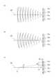
また、4つの超音波素子アレイ4Lを適切に駆動することで、強干渉領域5を形成することができる理由は次のようなものである。図5は、4つの超音波素子アレイ4Lを適切に駆動することで強干渉領域5を形成可能な理由についての説明図である。簡単のために、先ず初めは、超音波素子アレイ4Lが、中央の2つの超音波素子アレイ4L(超音波素子アレイ4Lbおよび超音波素子アレイ4Lc)であるものとして説明する。The reason why the
図5(a)に示すように、2つの超音波素子アレイ4Lbと超音波素子アレイ4Lcとの間を垂直に二等分する平面(以下、垂直二等分面CP)を考える。尚、図5では、超音波素子アレイ4Lbおよび超音波素子アレイ4Lcは白丸として表示されており、CPは一点鎖線の直線として表示されている。垂直二等分面CPは、2つの超音波素子アレイ4Lbと超音波素子アレイ4Lcとの間を垂直に二等分しているから、垂直二等分面CP上の任意の点は、超音波素子アレイ4Lbまでの距離と、超音波素子アレイ4Lcまでの距離とが等しくなる。従って、超音波素子アレイ4Lbおよび超音波素子アレイ4Lcから同じ周波数で同じ位相の超音波を放出した場合、垂直二等分面CP上の任意の点で、超音波素子アレイ4Lbから到達した超音波が山(圧力が最大の状態)であれば、超音波素子アレイ4Lcから到達した超音波も山となる。逆に、超音波素子アレイ4Lbから到達した超音波が谷(圧力が最小の状態)であれば、超音波素子アレイ4Lcから到達した超音波も谷となる。As shown in FIG. 5(a), consider a plane (hereinafter, perpendicular bisection plane CP) that vertically bisects the two ultrasonic element arrays 4Lb and 4Lc. In FIG. 5, the ultrasonic element arrays 4Lb and 4Lc are displayed as white circles, and the CP is displayed as a dashed line. Since the perpendicular bisection plane CP vertically bisects the two ultrasonic element arrays 4Lb and 4Lc, the distance to the ultrasonic element array 4Lb and the distance to the ultrasonic element array 4Lc are equal at any point on the perpendicular bisection plane CP. Therefore, when ultrasonic waves of the same frequency and phase are emitted from the ultrasonic element array 4Lb and the ultrasonic element array 4Lc, if the ultrasonic waves arriving from the ultrasonic element array 4Lb are crests (maximum pressure state) at any point on the perpendicular bisection plane CP, the ultrasonic waves arriving from the ultrasonic element array 4Lc are also crests. Conversely, if the ultrasonic waves arriving from the ultrasonic element array 4Lb are a valley (a state where pressure is at a minimum), the ultrasonic waves arriving from the ultrasonic element array 4Lc will also be a valley.
図5(a)中に実線を用いて表示された複数の円弧は、超音波素子アレイ4Lbから放出される超音波の山の位置を概念的に表しており、円弧と円弧との中間の箇所が、超音波の谷の位置となる。また、図5(a)中に破線を用いて表示された複数の円弧は、超音波素子アレイ4Lcから放出される超音波の山の位置を概念的に表しており、円弧と円弧との中間の箇所が、超音波の谷の位置となる。図5(a)に示されるように、垂直二等分面CPの上では、直線の円弧と破線の円弧とが交差している。このことは、垂直二等分面CP上では、超音波素子アレイ4Lbの超音波と超音波素子アレイ4Lcの超音波とが強め合う干渉を起こすことを示している。The multiple arcs shown using solid lines in FIG. 5(a) conceptually represent the positions of the peaks of the ultrasonic waves emitted from the ultrasonic element array 4Lb, and the midpoints between the arcs are the positions of the valleys of the ultrasonic waves. The multiple arcs shown using dashed lines in FIG. 5(a) conceptually represent the positions of the peaks of the ultrasonic waves emitted from the ultrasonic element array 4Lc, and the midpoints between the arcs are the positions of the valleys of the ultrasonic waves. As shown in FIG. 5(a), the straight arcs and dashed arcs intersect on the perpendicular bisecting plane CP. This indicates that the ultrasonic waves of the ultrasonic element array 4Lb and the ultrasonic waves of the ultrasonic element array 4Lc cause constructive interference on the perpendicular bisecting plane CP.
参考として、図5(b)には、超音波素子アレイ4Lbの超音波に対して、超音波素子アレイ4Lcの超音波の位相を、半波長だけ遅らせた場合を示している。図5(b)に示されるように、垂直二等分面CP上では、破線の円弧(超音波素子アレイ4Lcの超音波の山の位置)は、実線の円弧(超音波素子アレイ4Lbの超音波の山の位置)の間を通過している。このことは、位相を半波長ずらした場合、垂直二等分面CP上では、超音波素子アレイ4Lbの超音波と超音波素子アレイ4Lcの超音波とが弱め合う干渉を起こすことを示している。For reference, FIG. 5(b) shows a case where the phase of the ultrasonic waves of the ultrasonic element array 4Lc is delayed by half a wavelength relative to the ultrasonic waves of the ultrasonic element array 4Lb. As shown in FIG. 5(b), on the perpendicular bisecting plane CP, the dashed arc (the position of the ultrasonic wave crest of the ultrasonic element array 4Lc) passes between the solid arc (the position of the ultrasonic wave crest of the ultrasonic element array 4Lb). This shows that when the phase is shifted by half a wavelength, the ultrasonic waves of the ultrasonic element array 4Lb and the ultrasonic waves of the ultrasonic element array 4Lc cause destructive interference on the perpendicular bisecting plane CP.
以上に説明したように、超音波素子アレイ4Lbおよび超音波素子アレイ4Lcから、周波数が同じで位相も同じ超音波を放出すると、超音波素子アレイ4Lbおよび超音波素子アレイ4Lcの垂直二等分面CP上では、(何処でも)2つの超音波素子アレイ4Lからの超音波が強め合う干渉を起こすことになる。As described above, when ultrasonic waves of the same frequency and phase are emitted from the ultrasonic element array 4Lb and the ultrasonic element array 4Lc, constructive interference occurs between the ultrasonic waves from the two
また、超音波素子アレイ4Laから放出される超音波についても、超音波素子アレイ4Lbから放出される超音波に対して、適切な量だけ位相をずらしてやれば、垂直二等分面CP上で超音波素子アレイ4Laと超音波素子アレイ4Lbとが強め合う干渉を起こすようにすることができる。この理由について図5(c)を用いて説明する。図5(c)に示したように、垂直二等分面CP上の任意の位置にP点を考える。P点から超音波素子アレイ4Laまでの距離は、P点から超音波素子アレイ4Lbまでの距離よりも長いから、超音波素子アレイ4Laおよび超音波素子アレイ4Lbから同じ位相の超音波を放出しても、垂直二等分面CP上で強め合う干渉を生じさせることはできない。Furthermore, if the ultrasonic waves emitted from the ultrasonic element array 4La are shifted in phase by an appropriate amount relative to the ultrasonic waves emitted from the ultrasonic element array 4Lb, constructive interference can be caused between the ultrasonic element array 4La and the ultrasonic element array 4Lb on the perpendicular bisecting plane CP. The reason for this will be explained using FIG. 5(c). As shown in FIG. 5(c), consider point P at any position on the perpendicular bisecting plane CP. Since the distance from point P to the ultrasonic element array 4La is longer than the distance from point P to the ultrasonic element array 4Lb, even if ultrasonic waves of the same phase are emitted from the ultrasonic element array 4La and the ultrasonic element array 4Lb, constructive interference cannot be caused on the perpendicular bisecting plane CP.
ここで、図5(c)に示すように、超音波素子アレイ4Laと超音波素子アレイ4Lbとの間に中点(以下、Q点)を取って、P点とQ点とを結ぶ直線が垂直二等分面CPとなす角度をθとする。すると、P点から超音波素子アレイ4Laまでの距離と、P点から超音波素子アレイ4Lbまでの距離の差は、
dL = du・sinθ
で近似することができる。ここで、duは、超音波素子アレイ4Laと超音波素子アレイ4Lbとの距離である。また、P点までの距離は超音波素子アレイ4Lbよりも超音波素子アレイ4Laの方が遠いから、超音波素子アレイ4Laからの超音波が超音波素子アレイ4Lbからの超音波よりも、dLだけ遅れてP点に到着することになる。従って、dLに相当する位相Φ(=(2π・du/超音波の波長)・sinθ)だけ、超音波素子アレイ4Laの超音波を進めておけば、P点上で超音波素子アレイ4Laの超音波と超音波素子アレイ4Lbの超音波とで強め合う干渉を生じさせることができる。 5C, a midpoint (hereinafter, point Q) is taken between the ultrasonic element array 4La and the ultrasonic element array 4Lb, and the angle between the straight line connecting point P and point Q and the perpendicular bisector CP is defined as θ. Then, the difference between the distance from point P to the ultrasonic element array 4La and the distance from point P to the ultrasonic element array 4Lb is given by:
dL = du sin θ
Here, du is the distance between the ultrasonic element array 4La and the ultrasonic element array 4Lb. In addition, since the ultrasonic element array 4La is farther from the ultrasonic element array 4Lb to the point P, the ultrasonic waves from the ultrasonic element array 4La arrive at the point P with a delay of dL from the ultrasonic waves from the ultrasonic element array 4Lb. Therefore, if the ultrasonic waves of the ultrasonic element array 4La are advanced by a phase Φ (= (2π · du / ultrasonic wave wavelength) · sin θ) corresponding to dL, constructive interference can be generated between the ultrasonic waves of the ultrasonic element array 4La and the ultrasonic waves of the ultrasonic element array 4Lb at the point P.
尚、上述した近似式が成り立つのは、θが小さい場合に限られる。従って、P点がある程度まで超音波素子アレイ4Lに近付くと、それ以降は超音波素子アレイ4Lに近付くほど、強め合う干渉が弱くなる。このことから、超音波素子アレイ4Lの近く(従って、乾燥室3の壁面付近)では、超音波素子アレイ4Laの超音波と超音波素子アレイ4Lbの超音波とで強め合う干渉は生じない。The above approximation formula only holds when θ is small. Therefore, when point P approaches the
また、超音波素子アレイ4Laと超音波素子アレイ4Ldとについては、前述した超音波素子アレイ4Lbと超音波素子アレイ4Lcと全く同じように考えることができる。すなわち、超音波素子アレイ4Laおよび超音波素子アレイ4Ldから、周波数が同じで位相も同じ超音波を放出すると、超音波素子アレイ4Laおよび超音波素子アレイ4Ldの垂直二等分面CP上では、(何処でも)2つの超音波素子アレイ4Lからの超音波が強め合う干渉を起こすことになる。そして、上述したように、超音波素子アレイ4Laの超音波の位相は、超音波素子アレイ4Lbの超音波の位相に対して位相Φだけ進めているから、超音波素子アレイ4Ldの超音波の位相も、超音波素子アレイ4Lcの超音波の位相に対して位相Φだけ進んでいることになる。このため、超音波素子アレイ4Ldの超音波および超音波素子アレイ4Lcの超音波も、垂直二等分面CP上で強め合う干渉を生じさせる。結局、4つの超音波素子アレイ4Lから放出される全ての超音波が、垂直二等分面CP上で強め合う干渉を生じさせることになる。The ultrasonic element array 4La and the ultrasonic element array 4Ld can be considered in exactly the same way as the ultrasonic element array 4Lb and the ultrasonic element array 4Lc described above. That is, when ultrasonic waves with the same frequency and phase are emitted from the ultrasonic element array 4La and the ultrasonic element array 4Ld, the ultrasonic waves from the two
上述した実施例では、乾燥室3内で強干渉領域5が形成される位置は固定されており、超音波乾燥装置1のユーザは、手などの乾燥対象物を乾燥室3内に挿入した後、ゆっくりと乾燥対象物を引き上げるものとして説明した。しかし、乾燥室3内で強干渉領域5が形成される位置を移動させてもよい。In the above-described embodiment, the position where the
図6は、乾燥室3内で強干渉領域5の位置を移動させる変形例の超音波乾燥装置1の動作を示した説明図である。図示した変形例の超音波乾燥装置1でも、ユーザが手などの乾燥対象物を開口部2oから乾燥室3内に挿入すると、投光部6からの光が遮られて受光部7に届かなくなるので、乾燥対象物が挿入されたことを検知する。すると、コントローラ10(図1参照)がそれぞれの超音波素子アレイ4Lに対して駆動信号を出力することで、超音波素子アレイ4Lから超音波が放出される。Figure 6 is an explanatory diagram showing the operation of a modified
ここで、変形例の超音波乾燥装置1では、コントローラ10がそれぞれの超音波素子アレイ4Lに出力する駆動信号の位相を変更することで、強干渉領域5の位置を上から下へと移動させることが可能となっている。強干渉領域5の位置を移動させることが可能な理由については後述する。そして、強干渉領域5を一番下まで移動させたら、一番上の位置までジャンプさせた後、再び上から下へと移動させる動作を繰り返す。こうすれば、ユーザは手などの乾燥対象物を乾燥室3内に挿入した後、乾燥対象物を引き上げなくても、強干渉領域5が勝手に上から下へと移動して、手などに付着した水分を下方に押し下げて除去してくれるので、迅速に乾燥させることが可能となる。Here, in the
尚、変形例では、ユーザが乾燥対象物を乾燥室3内に挿入している限り、強干渉領域5を上から下へと移動させる動作を繰り返すものとしているが、強干渉領域5を上から下へと移動させる動作が所定回数(例えば5回)に達したら、超音波の放出を停止するようにしてもよい。こうすれば、乾燥対象物が乾燥した後も、無駄に超音波が照射されてしまうことを防止することができる。また、それぞれの超音波素子アレイ4Lに出力する駆動信号の位相を制御することで、強干渉領域5の位置を移動させることが可能な理由は次のようなものである。In the modified example, the
図7は、超音波素子アレイ4Lbから放出される超音波に対して、超音波素子アレイ4Lcから放出される超音波の位相が少しだけ進んでいる場合を例示した説明図である。図中に実線で示した複数の円弧は、超音波素子アレイ4Lbから放出される超音波の山の位置を表しており、図中に破線で示した複数の円弧は、超音波素子アレイ4Lcから放出される超音波の山の位置を表している。尚、超音波の周波数は、超音波素子アレイ4Lbの超音波も、超音波素子アレイ4Lcの超音波も同じである。Figure 7 is an explanatory diagram illustrating a case where the phase of the ultrasound emitted from the ultrasonic element array 4Lc is slightly advanced relative to the ultrasound emitted from the ultrasonic element array 4Lb. The multiple arcs shown by solid lines in the figure represent the positions of the peaks of the ultrasound emitted from the ultrasonic element array 4Lb, and the multiple arcs shown by dashed lines in the figure represent the positions of the peaks of the ultrasound emitted from the ultrasonic element array 4Lc. The frequency of the ultrasound is the same for both the ultrasound from the ultrasonic element array 4Lb and the ultrasound from the ultrasonic element array 4Lc.
超音波素子アレイ4Lbの超音波と、超音波素子アレイ4Lcの超音波とは位相がずれているので、図7(a)に示したように、超音波素子アレイ4Lbと超音波素子アレイ4Lcとの間を垂直に二等分する平面(垂直二等分面CP)上では、強め合う干渉は起こらない。しかし、超音波素子アレイ4Lbの超音波の位相が、超音波素子アレイ4Lcの超音波の位相に対して進んでいるということは、超音波素子アレイ4Lbの位置が、超音波素子アレイ4Lcの位置に対して少し前にあることと等価と考えることができる。すなわち、図7(b)に示すように、超音波素子アレイ4Lbの位置から超音波の放出方向に向かって、位相差の分だけ移動した位置に存在する仮想的な超音波素子アレイ4Lbvを想定して、その仮想的な超音波素子アレイ4Lbvから、超音波素子アレイ4Lcと同じ位相で同じ周波数の超音波を放出させる。こうすれば、仮想的な超音波素子アレイ4Lbvが放出する超音波と、実際の超音波素子アレイ4Lbが放出する超音波とは、区別が付かなくなる(すなわち、等価となる)。Since the ultrasonic waves of the ultrasonic element array 4Lb and the ultrasonic element array 4Lc are out of phase with each other, as shown in FIG. 7(a), constructive interference does not occur on the plane (perpendicular bisecting plane CP) that vertically bisects the ultrasonic element array 4Lb and the ultrasonic element array 4Lc. However, the fact that the phase of the ultrasonic waves of the ultrasonic element array 4Lb is advanced relative to the phase of the ultrasonic waves of the ultrasonic element array 4Lc can be considered equivalent to the position of the ultrasonic element array 4Lb being slightly ahead of the position of the ultrasonic element array 4Lc. That is, as shown in FIG. 7(b), a virtual ultrasonic element array 4Lbv is assumed to exist at a position moved by the phase difference from the position of the ultrasonic element array 4Lb toward the direction of ultrasonic emission, and ultrasonic waves of the same phase and frequency as the ultrasonic element array 4Lc are emitted from the virtual ultrasonic element array 4Lbv. In this way, the ultrasound emitted by the virtual ultrasonic element array 4Lbv and the ultrasound emitted by the actual ultrasonic element array 4Lb become indistinguishable (i.e., they become equivalent).
そこで、超音波素子アレイ4Lcとは異なる位相の超音波を放出する超音波素子アレイ4Lbを、超音波素子アレイ4Lcと同じ位相の超音波を放出する仮想的な超音波素子アレイ4Lbvに置き換えて考えれば、これらの超音波が強め合う干渉を発生させる平面は、超音波素子アレイ4Lcと仮想的な超音波素子アレイ4Lbvとの間を垂直に二等分する平面CPvとなることが分かる。If we consider replacing the ultrasonic element array 4Lb, which emits ultrasonic waves of a different phase from the ultrasonic element array 4Lc, with a virtual ultrasonic element array 4Lbv, which emits ultrasonic waves of the same phase as the ultrasonic element array 4Lc, it can be seen that the plane in which these ultrasonic waves generate constructive interference is the plane CPv that perpendicularly bisects the space between the ultrasonic element array 4Lc and the virtual ultrasonic element array 4Lbv.
図3~図5を用いて前述した本実施例では、超音波素子アレイ4Lbと超音波素子アレイ4Lcとは同じ位相の超音波を放出し、超音波素子アレイ4Laと超音波素子アレイ4Ldとも同じ位相の超音波を放出していた。このため、超音波素子アレイ4Lbと超音波素子アレイ4Lcとの間の垂直二等分面CP上で強め合う干渉が生じていた。これに対して、超音波素子アレイ4Lbの超音波と超音波素子アレイ4Lcの超音波との間に位相差を設け、同様に、超音波素子アレイ4Laの超音波と超音波素子アレイ4Ldの超音波との間にも位相差を設ければ、図7を用いて説明した理由から、4つの超音波素子アレイ4Lの超音波が強め合う干渉となる強干渉領域5を、垂直二等分面CPから平面CPvに移動させることができる。更に、位相差を連続して変更すれば、強干渉領域5の位置を連続して移動させることが可能となる。In the present embodiment described above with reference to Figures 3 to 5, the ultrasonic element arrays 4Lb and 4Lc emit ultrasonic waves of the same phase, and the ultrasonic element arrays 4La and 4Ld also emit ultrasonic waves of the same phase. For this reason, constructive interference occurs on the perpendicular bisector CP between the ultrasonic element arrays 4Lb and 4Lc. In contrast, if a phase difference is provided between the ultrasonic waves of the ultrasonic element arrays 4Lb and the ultrasonic waves of the ultrasonic element arrays 4Lc, and similarly, a phase difference is provided between the ultrasonic waves of the ultrasonic element arrays 4La and the ultrasonic elements arrays 4Ld, the
最後に、超音波を物体に照射すると一方向の力(本明細書中でいう音響放射力)が物体の表面に作用する理由について説明する。気体の分子運動論では、気体の圧力は、気体中で自由運動している分子が物体の表面に衝突することによって生じるものと考えられている。気体中の分子は全方向に向かって万遍なく飛翔しており、飛翔速度は、温度によって決まる速度分布を有していると考えられるから、それら全ての分子の運動を、物体の表面に向かって垂直に、代表的な速度Vxで飛翔する分子で代表させることができる。すると、質量mの1つの分子が衝突することによって物体の表面に及ぼす運動量は、2m・Vxとなる。気体の圧力は、このような衝突が一定頻度で繰り返されることによって生じるから、単位時間あたりに及ぼす運動量を求めると、
単位時間あたりに及ぼす運動量=2m・ρ・(Vx)*2 ・・・・・(1)
となる。ここで、ρは分子の密度であり、「*2」はべき乗を表している。 Finally, we will explain why a unidirectional force (referred to as acoustic radiation force in this specification) acts on the surface of an object when ultrasonic waves are irradiated to the object. In the molecular kinetic theory of gas, it is believed that gas pressure is generated by molecules moving freely in the gas colliding with the surface of the object. Since the molecules in the gas fly evenly in all directions and their flight speed is considered to have a speed distribution determined by the temperature, the motion of all of these molecules can be represented by a molecule flying perpendicularly toward the surface of the object at a representative speed Vx. Then, the momentum exerted on the surface of the object by the collision of one molecule of mass m is 2m·Vx. Gas pressure is generated by such collisions being repeated at a constant frequency, so the momentum exerted per unit time can be calculated as follows:
Momentum per unit time = 2m ρ (Vx) * 2 (1)
Here, ρ is the density of the molecule, and “*2” represents the power.
一方、超音波は、大気圧を中心として正圧の部分と負圧の部分とが交互に繰り返される縦波であるから、超音波が照射された物体の表面では、大気圧を中心として圧力の増減が繰り返される。ここで、上述したように気体の圧力は分子の衝突によるものであり、圧力が高くなることは分子が衝突する速度が増加したことを表し、圧力が低くなることは衝突する速度が減少したことを表している。従って、超音波が衝突した物体の表面で圧力が増減するということは、分子が衝突する速度が、大気圧に相当する速度Vxを中心として、超音波による圧力増減量に相当する速度Vsの範囲で増減していることになる。以下では、Vxを中心としてVsの範囲で増減している状況を、Vx±Vsと表記する。従って、超音波を物体に照射した時に、気体の分子が物体の表面に及ぼす運動量は、(1)式のVxを、(Vx±Vs)に置き換えると、
超音波による運動量=2m・ρ・(Vx±Vs)*2
となる。そして、この式を変形すると、
超音波による運動量=2m・ρ・Vx*2
+4m・ρ・Vx・(±Vs)
+2m・ρ・(±Vs)*2
となる。変形して得られた1項目は大気圧に相当する成分であり、2項目および3項目が超音波が照射されたことによる成分である。また、2項目の成分は(±Vs)を有することから明らかなように、時間と共に正負に変動する成分であるため、一定時間で平均するとキャンセルされてしまう。ところが、3項目の成分は大きさが0になることはあっても負になることはないので、一定時間で平均すると正の値が残ってしまう。従って、物体に超音波を照射すると、物体の表面には、大気圧の他に3項目の成分に相当する圧力が加わることになる。この3項目の成分に相当する圧力が、音響放射圧に対応する。 On the other hand, since ultrasonic waves are longitudinal waves in which positive and negative pressures are alternately repeated around atmospheric pressure, the pressure on the surface of an object irradiated with ultrasonic waves repeatedly increases and decreases around atmospheric pressure. Here, as described above, the pressure of the gas is caused by collisions of molecules, and an increase in pressure indicates an increase in the speed at which the molecules collide, and a decrease in pressure indicates a decrease in the speed at which the molecules collide. Therefore, the increase or decrease in pressure on the surface of an object irradiated with ultrasonic waves means that the speed at which the molecules collide increases or decreases within a range of speed Vs corresponding to the amount of pressure increase or decrease caused by ultrasonic waves, with speed Vx corresponding to atmospheric pressure as the center. Hereinafter, the situation in which the pressure increases or decreases within the range of Vs with Vx as the center will be expressed as Vx±Vs. Therefore, when ultrasonic waves are irradiated to an object, the momentum of the gas molecules exerted on the surface of the object is expressed as follows, by replacing Vx in formula (1) with (Vx±Vs):
Momentum due to ultrasound = 2m ρ (Vx ± Vs) * 2
And by transforming this formula, we get
Momentum due to ultrasound = 2m・ρ・Vx*2
+4m ρ Vx (± Vs)
+2m ρ (±Vs) * 2
The first item obtained by the transformation is a component corresponding to atmospheric pressure, while the second and third items are components resulting from the irradiation of ultrasonic waves. Furthermore, as is clear from the fact that the second item has (±Vs), it is a component that fluctuates positively and negatively with time, and therefore cancels out when averaged over a certain period of time. However, the third item's magnitude may become 0 but never negative, so a positive value remains when averaged over a certain period of time. Therefore, when an object is irradiated with ultrasonic waves, pressure equivalent to the three components, in addition to atmospheric pressure, is applied to the surface of the object. The pressure equivalent to these three components corresponds to acoustic radiation pressure.
以上に詳しく説明したように、本実施例および変形例の超音波乾燥装置1では、乾燥室3内に挿入した乾燥対象物に対して超音波を照射することで、乾燥対象物の表面に付着した水分を押し分けることによって除去することができる。このため、水分を周囲に飛散させたり、霧状の水分を周囲に拡散させたりすることなく、乾燥対象物を迅速に乾燥させることができる。As described above in detail, in the
また、複数の超音波素子4から放出される超音波を平面状の強干渉領域5に集中させて水分を除去するので、個々の超音波素子4は強力な超音波を放出する必要がなく、小さな超音波素子4を使用することができる。加えて、平面状の強干渉領域5は、複数の超音波素子4からの超音波に強め合う干渉を生じさせることによって形成されるので、強干渉領域5の厚さは薄く(超音波素子4が超音波を放出する放出面の大きさに相当する厚さ程度まで薄く)なる。一般に、超音波素子4から放出された超音波は進行方向に広がるが、複数の超音波素子4から放出される超音波を、薄い強干渉領域5に集中させることができるので、より一層小さな超音波素子4を使用することが可能となる。In addition, since the ultrasonic waves emitted from the multiple
更に、乾燥対象物の表面に付着した水分を、超音波で霧化させているのではなく、超音波で移動させるだけなので、それほど強力な超音波を使用する必要が無い。このため、乾燥対象物にダメージを与えることがなく、特に手を乾燥させる場合は、ユーザが超音波を痛く感じて不快な思いをさせる事態を回避することが可能となる。In addition, because the water adhering to the surface of the object to be dried is not atomized by ultrasound but is simply moved by ultrasound, there is no need to use very powerful ultrasound. This means that the object to be dried is not damaged, and it is possible to avoid situations in which the user feels discomfort due to the pain caused by the ultrasound, particularly when drying hands.
以上、本実施例および変形例の超音波乾燥装置1について説明したが、本発明は上記の実施例および変形例に限られるものではなく、その要旨を逸脱しない範囲で種々の態様で実施することが可能である。The above describes the
たとえば、上述した本実施例および変形例の超音波乾燥装置1では、複数の超音波素子4が同じ周波数の超音波を放出するものとしているが、超音波の周波数は完全に同じ周波数でなくても構わない。例えば、高い周波数の超音波を放出する超音波素子4と、低い周波数の超音波を放出する超音波素子4とが混在している場合でも、それらの超音波の周波数の差が数Hz~数十Hz程度であれば、(数Hz~数十Hz程度の唸りが生じるものの)本実施例および変形例の超音波乾燥装置1と同様のメカニズムによって、乾燥対象物を迅速に乾燥させることが可能となる。For example, in the
1…超音波乾燥装置、 2…本体ケース、 2o…開口部、
2s…電源スイッチ、 3…乾燥室、 3a…内壁面、 3d…ドレン穴、
4…超音波素子、 4L…超音波素子アレイ、 5…強干渉領域、
6…投光部、 7…受光部、 8…ドレンタンク、 8h…ドレンホース、
10…コントローラ、 CP…垂直二等分面。 1... ultrasonic drying device, 2... main body case, 2o... opening,
2s...power switch; 3...drying chamber; 3a...inner wall surface; 3d...drain hole;
4...ultrasonic element, 4L...ultrasonic element array, 5...strong interference region,
6...light projecting unit, 7...light receiving unit, 8...drain tank, 8h...drain hose,
10...controller; CP...perpendicular bisection plane.
Claims (6)
Translated fromJapanese前記開口部から前記乾燥対象物が挿入される挿入方向に対して側方に存在する前記乾燥室の内壁面上に配列された複数の超音波素子と、
前記複数の超音波素子を駆動することによって、前記乾燥室内に向けて前記超音波を放出させる超音波素子駆動部と
を備え、
前記超音波素子駆動部は、前記複数の超音波素子から前記超音波を放出させると共に、前記複数の超音波素子の間での前記超音波の位相差を制御することによって、前記複数の超音波素子から放出される前記超音波を用いて、前記乾燥対象物上で互いに強め合う干渉を生じさせる
ことを特徴とする超音波乾燥装置。 1. An ultrasonic drying device for drying an object to be dried by irradiating ultrasonic waves onto the object to be dried inserted into a drying chamber through an opening of the drying chamber,
A plurality of ultrasonic elements are arranged on an inner wall surface of the drying chamber that is located to the side with respect to an insertion direction in which the object to be dried is inserted through the opening;
an ultrasonic element driving unit that drives the plurality of ultrasonic elements to emit the ultrasonic waves toward the drying chamber,
the ultrasonic element driving unit causes the ultrasonic elements to emit ultrasonic waves, and controls a phase difference of the ultrasonic waves among the ultrasonic elements, thereby generating constructive interference between the ultrasonic waves emitted from the ultrasonic elements on the object to be dried.
前記超音波素子駆動部は、前記複数の超音波素子から放出される前記超音波が、前記挿入方向に対して交差する平面上で互いに強め合う干渉となるように、前記複数の超音波素子の間での前記超音波の位相差を制御する
ことを特徴とする超音波乾燥装置。 2. The ultrasonic drying device according to claim 1,
the ultrasonic element driving unit controls a phase difference of the ultrasonic waves among the plurality of ultrasonic elements so that the ultrasonic waves emitted from the plurality of ultrasonic elements constructively interfere with each other on a plane intersecting the insertion direction.
前記乾燥室内に挿入される前記乾燥対象物を検知する検知部を備え、
前記超音波素子駆動部は、前記検知部で前記乾燥対象物が検知された場合に、前記複数の超音波素子の駆動を開始する
ことを特徴とする超音波乾燥装置。 The ultrasonic drying device according to claim 1 or 2,
a detection unit that detects the object to be dried inserted into the drying chamber,
the ultrasonic element driving unit starts driving the ultrasonic elements when the object to be dried is detected by the detection unit.
前記超音波素子駆動部は、前記複数の超音波素子の間での前記超音波の位相差を変更することによって、前記複数の超音波素子から放出される前記超音波が互いに強め合う干渉となる位置が、前記挿入方向に移動する
ことを特徴とする超音波乾燥装置。 The ultrasonic drying device according to any one of claims 1 to 3,
the ultrasonic element driving unit changes a phase difference of the ultrasonic waves among the plurality of ultrasonic elements, thereby moving a position at which the ultrasonic waves emitted from the plurality of ultrasonic elements interfere with each other in a reinforced manner in the insertion direction.
前記乾燥室は、上面に前記開口部が形成されており、
前記複数の超音波素子は、斜め下方に向かって前記超音波を放出する
ことを特徴とする超音波乾燥装置。 The ultrasonic drying device according to any one of claims 1 to 4,
The drying chamber has the opening formed on an upper surface thereof,
The ultrasonic drying device according to claim 1, wherein the ultrasonic elements emit the ultrasonic waves obliquely downward.
前記複数の超音波素子は、前記乾燥対象物の挿入方向に対して側方で、且つ、互いに向き合う位置にある複数の前記内壁面上に配列されている
ことを特徴とする超音波乾燥装置。 The ultrasonic drying device according to any one of claims 1 to 5,
the ultrasonic elements are arranged on the inner wall surfaces at positions facing each other and laterally with respect to an insertion direction of the object to be dried.
Priority Applications (1)
| Application Number | Priority Date | Filing Date | Title |
|---|---|---|---|
| JP2021067975AJP7508404B2 (en) | 2021-04-13 | 2021-04-13 | Ultrasonic Drying Equipment |
Applications Claiming Priority (1)
| Application Number | Priority Date | Filing Date | Title |
|---|---|---|---|
| JP2021067975AJP7508404B2 (en) | 2021-04-13 | 2021-04-13 | Ultrasonic Drying Equipment |
Publications (2)
| Publication Number | Publication Date |
|---|---|
| JP2022162909A JP2022162909A (en) | 2022-10-25 |
| JP7508404B2true JP7508404B2 (en) | 2024-07-01 |
Family
ID=83724599
Family Applications (1)
| Application Number | Title | Priority Date | Filing Date |
|---|---|---|---|
| JP2021067975AActiveJP7508404B2 (en) | 2021-04-13 | 2021-04-13 | Ultrasonic Drying Equipment |
Country Status (1)
| Country | Link |
|---|---|
| JP (1) | JP7508404B2 (en) |
Families Citing this family (1)
| Publication number | Priority date | Publication date | Assignee | Title |
|---|---|---|---|---|
| JP7514806B2 (en) | 2021-08-17 | 2024-07-11 | 株式会社デンソー | Ultrasonic generator |
Citations (6)
| Publication number | Priority date | Publication date | Assignee | Title |
|---|---|---|---|---|
| JP2007185455A (en) | 2006-01-10 | 2007-07-26 | Akimoto Yonekura | Water remover after hand-washing which has ultrasonic moisture keeping function |
| JP2013184022A (en) | 2012-03-12 | 2013-09-19 | Systec:Kk | Ultrasonic hand dryer |
| JP2017522535A (en) | 2014-07-01 | 2017-08-10 | ヒート・テクノロジーズ、インコーポレイテッド | Indirect acoustic drying system and method |
| US20200080776A1 (en) | 2018-09-09 | 2020-03-12 | Ultrahaptics Limited | Ultrasonic-Assisted Liquid Manipulation |
| JP2020139637A (en) | 2019-02-26 | 2020-09-03 | Toa株式会社 | Acoustic dripping removal device and acoustic dripping removal method |
| CN212703380U (en) | 2020-05-19 | 2021-03-16 | 伯德创研(广州)生物科技有限公司 | Ultrasonic cleaning device with drying and disinfecting functions |
- 2021
- 2021-04-13JPJP2021067975Apatent/JP7508404B2/enactiveActive
Patent Citations (6)
| Publication number | Priority date | Publication date | Assignee | Title |
|---|---|---|---|---|
| JP2007185455A (en) | 2006-01-10 | 2007-07-26 | Akimoto Yonekura | Water remover after hand-washing which has ultrasonic moisture keeping function |
| JP2013184022A (en) | 2012-03-12 | 2013-09-19 | Systec:Kk | Ultrasonic hand dryer |
| JP2017522535A (en) | 2014-07-01 | 2017-08-10 | ヒート・テクノロジーズ、インコーポレイテッド | Indirect acoustic drying system and method |
| US20200080776A1 (en) | 2018-09-09 | 2020-03-12 | Ultrahaptics Limited | Ultrasonic-Assisted Liquid Manipulation |
| JP2020139637A (en) | 2019-02-26 | 2020-09-03 | Toa株式会社 | Acoustic dripping removal device and acoustic dripping removal method |
| CN212703380U (en) | 2020-05-19 | 2021-03-16 | 伯德创研(广州)生物科技有限公司 | Ultrasonic cleaning device with drying and disinfecting functions |
Also Published As
| Publication number | Publication date |
|---|---|
| JP2022162909A (en) | 2022-10-25 |
Similar Documents
| Publication | Publication Date | Title |
|---|---|---|
| JP7508404B2 (en) | Ultrasonic Drying Equipment | |
| US11740018B2 (en) | Ultrasonic-assisted liquid manipulation | |
| CN102665512B (en) | hand dryer | |
| US11365895B2 (en) | Floating-type humidifier having increased amount of humidification | |
| US10780606B2 (en) | Nanotube particle device and method for using the same | |
| US9308544B2 (en) | Atomization device | |
| US9144830B2 (en) | Static eliminating and dust removing apparatus | |
| US3292910A (en) | Ultrasonic concentrator | |
| CA2656975C (en) | Method and system for enhanced high intensity acoustic waves application | |
| WO2016029536A1 (en) | Surface acoustic wave touch screen and touch display apparatus | |
| US11415556B2 (en) | Acoustic wave superscattering | |
| US7950594B2 (en) | Mechanical and ultrasound atomization and mixing system | |
| KR20150135093A (en) | Integrated compact impingement on extended heat surface | |
| JP2012217876A (en) | Noncontact cleaning method using ultrasonic wave | |
| WO2017152409A1 (en) | Ultrasonic cleaning robot | |
| TW200906334A (en) | Portable ultrasonic mist generating facial treatment apparatus | |
| US20090165830A1 (en) | Ultrasound Actuator for Cleaning Objects | |
| WO2020131460A1 (en) | Adjustable misting arrays | |
| Soennecken et al. | Waveguide based acoustic levitation device for moving objects in a large volume | |
| JP2007162997A (en) | Dry fog generator | |
| JP2505143B2 (en) | Focused ultrasonic generator | |
| JP2021081166A (en) | Drying device | |
| CN104684448B (en) | Hand drying device | |
| JPH10243995A (en) | Negative ion generating device | |
| KR102301120B1 (en) | Apparatus and method for controlling humidity |
Legal Events
| Date | Code | Title | Description |
|---|---|---|---|
| A621 | Written request for application examination | Free format text:JAPANESE INTERMEDIATE CODE: A621 Effective date:20231220 | |
| A977 | Report on retrieval | Free format text:JAPANESE INTERMEDIATE CODE: A971007 Effective date:20240521 | |
| TRDD | Decision of grant or rejection written | ||
| A01 | Written decision to grant a patent or to grant a registration (utility model) | Free format text:JAPANESE INTERMEDIATE CODE: A01 Effective date:20240528 | |
| A61 | First payment of annual fees (during grant procedure) | Free format text:JAPANESE INTERMEDIATE CODE: A61 Effective date:20240619 | |
| R150 | Certificate of patent or registration of utility model | Ref document number:7508404 Country of ref document:JP Free format text:JAPANESE INTERMEDIATE CODE: R150 |