JP7508041B2 - Internal goods - Google Patents
Internal goodsDownload PDFInfo
- Publication number
- JP7508041B2 JP7508041B2JP2020178687AJP2020178687AJP7508041B2JP 7508041 B2JP7508041 B2JP 7508041B2JP 2020178687 AJP2020178687 AJP 2020178687AJP 2020178687 AJP2020178687 AJP 2020178687AJP 7508041 B2JP7508041 B2JP 7508041B2
- Authority
- JP
- Japan
- Prior art keywords
- wire
- coil
- catheter
- coil spring
- large diameter
- Prior art date
- Legal status (The legal status is an assumption and is not a legal conclusion. Google has not performed a legal analysis and makes no representation as to the accuracy of the status listed.)
- Active
Links
- 238000004804windingMethods0.000claimsdescription58
- 239000000835fiberSubstances0.000claimsdescription48
- 239000000463materialSubstances0.000claimsdescription41
- 229910052751metalInorganic materials0.000claimsdescription8
- 239000002184metalSubstances0.000claimsdescription8
- 229910000990Ni alloyInorganic materials0.000claimsdescription6
- 229910001069Ti alloyInorganic materials0.000claimsdescription6
- RTAQQCXQSZGOHL-UHFFFAOYSA-NTitaniumChemical compound[Ti]RTAQQCXQSZGOHL-UHFFFAOYSA-N0.000claimsdescription5
- 239000010936titaniumSubstances0.000claimsdescription5
- 230000015572biosynthetic processEffects0.000claimsdescription2
- 238000010586diagramMethods0.000description20
- 230000007547defectEffects0.000description18
- 208000035478Interatrial communicationDiseases0.000description12
- 208000013914atrial heart septal defectDiseases0.000description12
- 206010003664atrial septal defectDiseases0.000description12
- 229910045601alloyInorganic materials0.000description11
- 239000000956alloySubstances0.000description11
- 229920001577copolymerPolymers0.000description11
- 238000000034methodMethods0.000description8
- 239000004745nonwoven fabricSubstances0.000description8
- 210000005246left atriumAnatomy0.000description7
- 210000005245right atriumAnatomy0.000description7
- 239000002131composite materialSubstances0.000description6
- 210000003157atrial septumAnatomy0.000description5
- -1mesh shapeSubstances0.000description5
- 239000008280bloodSubstances0.000description4
- 210000004369bloodAnatomy0.000description4
- 208000028659dischargeDiseases0.000description4
- FYYHWMGAXLPEAU-UHFFFAOYSA-NMagnesiumChemical compound[Mg]FYYHWMGAXLPEAU-UHFFFAOYSA-N0.000description3
- 229920000954PolyglycolidePolymers0.000description3
- 238000004891communicationMethods0.000description3
- 239000003814drugSubstances0.000description3
- 229940079593drugDrugs0.000description3
- 238000009940knittingMethods0.000description3
- JJTUDXZGHPGLLC-UHFFFAOYSA-NlactideChemical compoundCC1OC(=O)C(C)OC1=OJJTUDXZGHPGLLC-UHFFFAOYSA-N0.000description3
- 230000007774longtermEffects0.000description3
- 229910052749magnesiumInorganic materials0.000description3
- 239000011777magnesiumSubstances0.000description3
- 230000007257malfunctionEffects0.000description3
- 150000002739metalsChemical class0.000description3
- 239000004633polyglycolic acidSubstances0.000description3
- 235000017060Arachis glabrataNutrition0.000description2
- 241001553178Arachis glabrataSpecies0.000description2
- 235000010777Arachis hypogaeaNutrition0.000description2
- 235000018262Arachis monticolaNutrition0.000description2
- PXHVJJICTQNCMI-UHFFFAOYSA-NNickelChemical compound[Ni]PXHVJJICTQNCMI-UHFFFAOYSA-N0.000description2
- CBENFWSGALASAD-UHFFFAOYSA-NOzoneChemical compound[O-][O+]=OCBENFWSGALASAD-UHFFFAOYSA-N0.000description2
- TZCXTZWJZNENPQ-UHFFFAOYSA-Lbarium sulfateChemical compound[Ba+2].[O-]S([O-])(=O)=OTZCXTZWJZNENPQ-UHFFFAOYSA-L0.000description2
- 238000005452bendingMethods0.000description2
- 210000005240left ventricleAnatomy0.000description2
- 210000004072lungAnatomy0.000description2
- 230000014759maintenance of locationEffects0.000description2
- 238000012986modificationMethods0.000description2
- 230000004048modificationEffects0.000description2
- 229910001000nickel titaniumInorganic materials0.000description2
- 235000020232peanutNutrition0.000description2
- 238000009832plasma treatmentMethods0.000description2
- BASFCYQUMIYNBI-UHFFFAOYSA-NplatinumChemical compound[Pt]BASFCYQUMIYNBI-UHFFFAOYSA-N0.000description2
- 229920000747poly(lactic acid)Polymers0.000description2
- 229920002463poly(p-dioxanone) polymerPolymers0.000description2
- 229920001610polycaprolactonePolymers0.000description2
- 239000004632polycaprolactoneSubstances0.000description2
- 239000002994raw materialSubstances0.000description2
- 210000005241right ventricleAnatomy0.000description2
- 102000008186CollagenHuman genes0.000description1
- 108010035532CollagenProteins0.000description1
- 108010010803GelatinProteins0.000description1
- 229910001252Pd alloyInorganic materials0.000description1
- 239000002202Polyethylene glycolSubstances0.000description1
- 239000004372Polyvinyl alcoholSubstances0.000description1
- 238000010521absorption reactionMethods0.000description1
- 210000000709aortaAnatomy0.000description1
- 230000001746atrial effectEffects0.000description1
- 230000000903blocking effectEffects0.000description1
- 238000009954braidingMethods0.000description1
- 229920001436collagenPolymers0.000description1
- 238000003851corona treatmentMethods0.000description1
- 238000002788crimpingMethods0.000description1
- 238000005520cutting processMethods0.000description1
- 238000000354decomposition reactionMethods0.000description1
- 238000007599dischargingMethods0.000description1
- 201000010099diseaseDiseases0.000description1
- 208000037265diseases, disorders, signs and symptomsDiseases0.000description1
- 238000010894electron beam technologyMethods0.000description1
- 239000004744fabricSubstances0.000description1
- 210000003191femoral veinAnatomy0.000description1
- 229920000159gelatinPolymers0.000description1
- 239000008273gelatinSubstances0.000description1
- 235000019322gelatineNutrition0.000description1
- 235000011852gelatine dessertsNutrition0.000description1
- PCHJSUWPFVWCPO-UHFFFAOYSA-NgoldChemical compound[Au]PCHJSUWPFVWCPO-UHFFFAOYSA-N0.000description1
- 239000010931goldSubstances0.000description1
- 229910052737goldInorganic materials0.000description1
- 210000002837heart atriumAnatomy0.000description1
- 238000010438heat treatmentMethods0.000description1
- 238000003384imaging methodMethods0.000description1
- 238000001990intravenous administrationMethods0.000description1
- 230000001788irregularEffects0.000description1
- 210000004115mitral valveAnatomy0.000description1
- 239000000203mixtureSubstances0.000description1
- 229920005615natural polymerPolymers0.000description1
- 229910052697platinumInorganic materials0.000description1
- 229920001223polyethylene glycolPolymers0.000description1
- 229920000642polymerPolymers0.000description1
- 229920002451polyvinyl alcoholPolymers0.000description1
- 210000001147pulmonary arteryAnatomy0.000description1
- 210000003492pulmonary veinAnatomy0.000description1
- 229920002379silicone rubberPolymers0.000description1
- 239000004945silicone rubberSubstances0.000description1
- 229920001059synthetic polymerPolymers0.000description1
- 229910002058ternary alloyInorganic materials0.000description1
- 210000000591tricuspid valveAnatomy0.000description1
- 210000001631vena cava inferiorAnatomy0.000description1
- 210000002620vena cava superiorAnatomy0.000description1
- XLYOFNOQVPJJNP-UHFFFAOYSA-NwaterSubstancesOXLYOFNOQVPJJNP-UHFFFAOYSA-N0.000description1
- 238000003466weldingMethods0.000description1
Images


Landscapes
- Surgical Instruments (AREA)
Description
Translated fromJapanese本発明は、内通物に関する。The present invention relates to an internal material.
従来から、管の内部を通される内通物として様々なものが使用されている。このうち、内通物が管の内部を通された後に管の内部から排出されることに伴って該内通物の一部が広がる構成のものがある。例えば、特許文献1には、カテーテルの内部を通される閉鎖栓(欠損孔閉鎖材)が開示されている。特許文献1の閉鎖栓は、コイルばねを有し、コイルばねを伸縮させることで、カテーテルの内部を通された後にカテーテルの内部から排出されることに伴って生体吸収性繊維で構成された第1の筒部及び第2の筒部を広げることが可能な構成となっている。Conventionally, various objects have been used as objects passed through the inside of a tube. Among these, there are some that are configured such that a part of the object expands as the object is discharged from the inside of the tube after being passed through it. For example,
特許文献1の閉鎖栓は、生体吸収性繊維がコイルばねの軸線方向における両端部に係合されている。しかしながら、特許文献1には詳細な構成が記載されていないが、内通物が管の内部を通された後に管の内部から排出されることに伴って繊維部が広がる構成であって、コイル部の巻き軸方向における一方側の端部と他方側の端部とに取り付けられた繊維部を備える内通物においては、繊維部とコイル部との取り付け構成が複雑になる傾向がある。単純にコイル部を構成する素線に繊維部の繊維を巻き付けるだけでは繊維の取り付け位置がずれるなどの弊害があるので、繊維部の繊維を取り付けるための専用の取り付け部をコイル部に設ける必要があったためである。In the closure plug of
そこで、本発明は、内通物が管の内部を通された後に管の内部から排出されることに伴って繊維部が広がる簡便な構成を提供することを目的にする。Therefore, the present invention aims to provide a simple structure in which the fiber portion expands as the material passes through the inside of the tube and is then discharged from the inside of the tube.
上記課題を解決するための本発明の第1の態様の内通物は、管の内部を通される内通物であって、素線を巻くことにより構成されるコイル部と、前記コイル部の巻き軸方向における一方側の端部と他方側の端部とに取り付けられた繊維部と、を備え、前記コイル部は、前記一方側の端部及び前記他方側の端部に前記繊維部の繊維を通す孔形成部が形成されるとともに、前記内通物が前記管の内部を通される際に前記巻き軸方向に延びた状態で通され、前記繊維部は、前記内通物が前記管の内部を通された後に前記管の内部から排出されることで前記コイル部が前記巻き軸方向に縮んだ状態となることに伴って、前記巻き軸方向から見て広がる構成となっていることを特徴とする。The first aspect of the present invention for solving the above problem is an inner article that is passed through the inside of a pipe, and includes a coil portion formed by winding a wire, and a fiber portion attached to one end and the other end of the coil portion in the winding axis direction, and the coil portion has hole formation portions at the one end and the other end for passing the fibers of the fiber portion, and when the inner article is passed through the inside of the pipe, it is passed in a state extended in the winding axis direction, and the fiber portion is configured to expand as viewed from the winding axis direction as the inner article is discharged from the inside of the pipe after passing through the inside of the pipe, causing the coil portion to contract in the winding axis direction.
本態様によれば、コイル部の巻き軸方向における一方側の端部と他方側の端部に繊維を通す孔形成部が形成される。このため、簡単に形成することができる孔形成部に繊維を通すことで繊維の取り付け位置がずれることを抑制できる。したがって、内通物が管の内部を通された後に管の内部から排出されることに伴って繊維部が広がる構成を簡便に形成できる。According to this aspect, a hole forming section for passing the fiber is formed at one end and the other end in the winding axis direction of the coil section. Therefore, by passing the fiber through the hole forming section, which can be easily formed, it is possible to prevent the attachment position of the fiber from shifting. Therefore, it is possible to easily form a configuration in which the fiber section expands as the internal object is discharged from inside the tube after passing through the inside of the tube.
本発明の第2の態様の内通物は、前記第1の態様において、前記孔形成部は、前記素線の巻き径を前記コイル部における他の部分よりも大きくすることで形成される大径部であることを特徴とする。The second aspect of the present invention is characterized in that in the first aspect, the hole forming portion is a large diameter portion formed by making the winding diameter of the wire larger than other portions of the coil portion.
本態様によれば、コイル部の巻き軸方向における一方側の端部と他方側の端部に繊維を通す大径部が形成される。このため、素線の巻き径を大きくするという簡単な方法で繊維を取り付ける部位としての大径部を形成できる。According to this embodiment, a large diameter section through which the fibers pass is formed at one end and the other end in the winding axis direction of the coil section. Therefore, a large diameter section as a section for attaching the fibers can be formed by the simple method of increasing the winding diameter of the wire.
本発明の第3の態様の内通物は、前記第2の態様において、前記コイル部には、前記巻き軸方向から前記コイル部を見た場合に、複数個所に前記繊維を通す孔部が形成されるように前記大径部が形成されていることを特徴とする。The third aspect of the present invention is characterized in that in the second aspect, the coil portion is formed with the large diameter portion so that holes for passing the fibers are formed in multiple places when the coil portion is viewed from the winding axis direction.
本態様によれば、コイル部には、巻き軸方向から該コイル部を見た場合に、複数個所に繊維を通す孔部が形成されるように大径部が形成されている。このため、1箇所だけに繊維を通す孔部が形成される構成に比べて、より確りと繊維部をコイル部に取り付けることができる。According to this aspect, the coil portion is formed with a large diameter portion so that, when the coil portion is viewed from the winding axis direction, multiple holes for passing the fibers through are formed. Therefore, the fiber portion can be attached to the coil portion more securely than in a configuration in which a hole for passing the fibers through is formed in only one place.
本発明の第4の態様の内通物は、前記第2または第3の態様において、前記コイル部には、前記巻き軸方向から前記コイル部を見た場合に、複数の前記大径部がオーバーラップするように形成されていることを特徴とする。The fourth aspect of the present invention is characterized in that in the second or third aspect, the coil portion is formed so that multiple large diameter portions overlap when the coil portion is viewed from the winding axis direction.
本態様によれば、コイル部には、巻き軸方向からコイル部を見た場合に、複数の大径部がオーバーラップするように形成されている。このため、1本あたりの繊維を複数の大径部の孔部に通すことができ、繊維を通す部分の強度を高くすることができる。According to this aspect, the coil portion is formed so that multiple large diameter portions overlap each other when viewed from the winding axis direction. This allows each fiber to pass through multiple holes in the large diameter portions, increasing the strength of the portion through which the fiber passes.
本発明の第5の態様の内通物は、前記第1から第4のいずれか1項の態様において、前記コイル部は、金属製であることを特徴とする。The fifth aspect of the present invention is an internal object according to any one of the first to fourth aspects, characterized in that the coil portion is made of metal.
本態様によれば、コイル部は金属製であるので、コイル部を高強度とすることができる。In this embodiment, the coil portion is made of metal, so the coil portion can be made strong.
本発明の第6の態様の内通物は、前記第5の態様において、前記コイル部は、ニッケル及びチタンの合金製であることを特徴とする。The sixth aspect of the present invention is the fifth aspect of the internal communication device, characterized in that the coil portion is made of an alloy of nickel and titanium.
本態様によれば、コイル部はニッケル及びチタンの合金製である。ニッケル及びチタンの合金は生体適合性が特に優れているので、例えば、医療用などの分野において特に好ましく使用することができる。According to this embodiment, the coil portion is made of an alloy of nickel and titanium. Nickel and titanium alloys have particularly excellent biocompatibility, and are therefore particularly suitable for use in fields such as medical applications.
本発明の第7の態様の内通物は、前記第1から第6のいずれか1項の態様において、前記管は、カテーテルであることを特徴とする。The seventh aspect of the present invention is characterized in that in any one of the first to sixth aspects, the tube is a catheter.
本態様によれば、カテーテル用の内通物として、内通物が管の内部を通された後に管の内部から排出されることに伴って繊維部が広がる構成を簡便に形成できる。According to this aspect, it is possible to easily form a catheter inner material in such a way that the fiber portion expands as the inner material is passed through the inside of the tube and then discharged from the inside of the tube.
本発明の第8の態様の内通物は、前記第7の態様において、前記コイル部は、前記カテーテルの内部を通すワイヤーに対する着脱部を有し、前記ワイヤーは、先端に回転可能な雄ネジ部を有し、前記着脱部は、前記コイル部の内側を前記雄ネジ部に対応する雌ネジ部としていることを特徴とする。The eighth aspect of the present invention is an internal communication object according to the seventh aspect, characterized in that the coil portion has a detachable portion for a wire passing through the inside of the catheter, the wire has a rotatable male thread portion at the tip, and the detachable portion has a female thread portion on the inside of the coil portion that corresponds to the male thread portion.
本態様によれば、コイル部の内側を雌ネジ部として着脱部を形成することで、着脱部を簡便に形成することができる。According to this aspect, the detachable part can be easily formed by forming the inside of the coil part as a female thread part.
本発明の第9の態様の内通物は、前記第8の態様において、前記着脱部は、前記雌ネジ部の外周を覆う管状部を有することを特徴とする。The ninth aspect of the present invention is an internal member according to the eighth aspect, characterized in that the detachable portion has a tubular portion that covers the outer periphery of the female threaded portion.
本態様によれば、着脱部は雌ネジ部の外周を覆う管状部を有するので、コイル部が径方向に広がってしまうことを抑制でき、コイル部である着脱部に雄ネジ部が差し込まれることで着脱部が径方向に広がってしまって着脱部の雌ネジ部が雌ネジ部としての役割を果たさなくなることを抑制できる。According to this aspect, the detachable portion has a tubular portion that covers the outer circumference of the female threaded portion, which prevents the coil portion from expanding radially. This prevents the detachable portion from expanding radially when the male threaded portion is inserted into the detachable portion, which is the coil portion, and prevents the female threaded portion of the detachable portion from failing to fulfill its role as a female threaded portion.
本発明の第10の態様の内通物は、前記第9の態様において、前記管状部は、前記一方側の端部から前記他方側の端部に亘って前記雌ネジ部の外周を覆っていることを特徴とする。The tenth aspect of the present invention is the ninth aspect of the internal thread, characterized in that the tubular portion covers the outer periphery of the female thread portion from the end on one side to the end on the other side.
コイル部の一方側の端部から他方側の端部までの距離が長くなるとコイル部に対して強固に管状部を固定することが困難になるが、本態様によれば、管状部は一方側の端部から他方側の端部に亘って雌ネジ部の外周を覆っていることで、コイル部に対して強固に管状部を固定できる。When the distance from one end of the coil portion to the other end becomes long, it becomes difficult to firmly fix the tubular portion to the coil portion. However, according to this embodiment, the tubular portion covers the outer periphery of the female thread portion from one end to the other end, so that the tubular portion can be firmly fixed to the coil portion.
本発明の第11の態様の内通物は、前記第7の態様において、前記コイル部に固定され、前記カテーテルの内部を通すワイヤーに対して着脱可能な着脱部を有し、前記着脱部は、糸状部材を通す貫通部が設けられ、前記糸状部材が前記貫通部に通されるとともに前記孔形成部に対しても通されることで前記コイル部の端部に固定され、前記ワイヤーは、先端に回転可能な雄ネジ部を有し、前記着脱部は、前記雄ネジ部に対応する雌ネジ部を有することを特徴とする。The eleventh aspect of the present invention is characterized in that the internal passage of the seventh aspect is fixed to the coil section and has a detachable part that is detachable from the wire passing through the inside of the catheter, the detachable part is provided with a through-hole for passing a filament, the filament is passed through the through-hole and also through the hole-forming part, and is fixed to the end of the coil section, the wire has a rotatable male thread at the tip, and the detachable part has a female thread corresponding to the male thread.
本態様によれば、ワイヤーの雄ネジ部に対応する雌ネジ部を有し、孔形成部を利用して糸状部材によりコイル部の端部に固定される、着脱部を有する。このため、ワイヤーに対してのネジの嵌合精度が高く簡単な構成の着脱部により、ワイヤーに対してコイル部を着脱することができる。According to this aspect, the detachable part has a female threaded part that corresponds to the male threaded part of the wire, and is fixed to the end of the coil part by a thread-like member using a hole forming part. Therefore, the coil part can be attached and detached from the wire by the detachable part with high screw fitting accuracy to the wire and a simple structure.
本発明の第12の態様の内通物は、前記第11の態様において、前記ワイヤーは、前記一方側の端部から前記他方側の端部まで前記コイル部の内側を通り、前記着脱部に接続されていることを特徴とする。The twelfth aspect of the present invention is an internal object of the eleventh aspect, characterized in that the wire passes inside the coil section from the one end to the other end and is connected to the detachable section.
本態様によれば、ワイヤーは一方側の端部から他方側の端部までコイル部の内側を通り着脱部に接続されている。このため、コイル部がワイヤーにより内側から補強され、コイル部がカテーテル内において折れ曲がることなどを抑制し、カテーテル内におけるワイヤーの挿入性を向上することができる。According to this embodiment, the wire passes through the inside of the coil section from one end to the other end and is connected to the detachable section. This allows the coil section to be reinforced from the inside by the wire, preventing the coil section from bending inside the catheter, and improving the insertability of the wire inside the catheter.
本発明の第13の態様の内通物は、前記第11または第12の態様において、前記糸状部材は、X線の不透過材を用いて形成されていることを特徴とする。The thirteenth aspect of the present invention is characterized in that in the eleventh or twelfth aspect, the thread-like member is formed using an X-ray opaque material.
本態様によれば、糸状部材はX線の不透過材を用いて形成されている。このため、医療現場においてX線を使用した際の視認性を向上することができる。According to this embodiment, the filamentous member is formed using an X-ray opaque material. This improves visibility when X-rays are used in the medical field.
本発明の第14の態様の内通物は、前記第1から第13のいずれか1つの態様において、前記繊維部は、前記内通物が前記管の内部を通された後に前記管の内部から排出されることで前記コイル部が前記巻き軸方向に縮んだ状態となることに伴って、前記巻き軸方向から見て前記一方側の端部側及び前記他方側の端部側の2か所で広がる構成となっていることを特徴とする。The inner material of the 14th aspect of the present invention is characterized in that, in any one of the first to 13th aspects, the fiber portion is configured to expand at two locations, the end side on one side and the end side on the other side, as viewed from the winding axis direction, as the inner material is passed through the inside of the tube and then discharged from the inside of the tube, causing the coil portion to contract in the winding axis direction.
本態様によれば、繊維部は、巻き軸方向から見て一方側の端部側及び他方側の端部側の2か所で広がる構成となっていることで、管の内部から排出する際に該2か所で対象となる孔を挟むように配置させ、該孔をふさぐことができる。According to this aspect, the fiber portion is configured to expand at two points, one end side and the other end side, when viewed from the winding axis direction, so that when it is discharged from inside the tube, the target hole can be sandwiched between the two points, thereby blocking the hole.
[実施例1](図1から図12)
以下に、本発明の実施形態に係る内通物1について、添付図面を参照して詳細に説明する。最初に、実施例1の内通物1について説明する。なお、本実施例の内通物1は、管としてのカテーテルの内部を通される内通物であって、心房中隔欠損症の患者に対するカテーテル治療に使用可能な欠損孔閉鎖材であるが、本発明の内通物は、欠損孔閉鎖材に限定されない。心房中隔欠損症以外の患者に対するカテーテル治療に使用可能な内通物であってもよいし、さらには、例えば工業用途の管などカテーテルなどの医療用途以外の管の内部を通される内通物であってもよい。なお、図1から図4及び図6から図9においては、コイルばね200の端部210に嵌められたパイプ240を省略して表している。 [Example 1] (FIGS. 1 to 12)
The
さらに、以下の実施の形態においては、内通物1の編み目状組織は生体吸収性繊維(線材の一例)を編成したものとして説明するが、本発明はこれに限定されるものではない。内通物1をカテーテル治療に使用する場合は、生体に形成された欠損孔を閉鎖するカテーテル治療ができる欠損孔閉鎖材が好ましいが、その編み目状組織は、生体吸収性繊維以外の線材で編成されていても構わない。なお、このような線材としては、形態保持性(形状保持性)を備えるためにある程度の硬度を備えることが好ましい。Furthermore, in the following embodiment, the knitted structure of the
(内通物の全体構成)
図1から図5などで表されるように、内通物1は、生体吸収性繊維の線材101を用いた編み目状組織の筒体100を備えている。筒体100の略中央部103の筒径は、他の部分の筒径よりも小さい。筒体100は、略中央部103を基準にして筒体100の長手方向Aの方向A1側の第1筒部110と、略中央部103を基準にして筒体100の長手方向Aの方向A2側の第2筒部120と、を有している。 (Overall composition of internal goods)
1 to 5, the
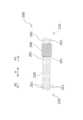
また、図1から図5などで表されるように、内通物1は、筒体100の内部に筒体100の長手方向Aを素線230(図5及び図10参照)の巻き軸方向とするコイルばね200を備えている。なお、コイルばね200の構成の詳細については後述するが、コイルばね200は、図10及び図11などで表されるように、方向A1側の端部210及び方向A2側の端部220に、その他の部分に比べて巻き径が1方向において大きい大径部201が設けられている。As shown in Figs. 1 to 5, the
筒体100における第1筒部110の方向A1側の端部の線材101は、コイルばね200に大径部201が形成されることで形成される孔部202(図11参照)に通され、このような構成となっていることで第1筒部110はコイルばね200に取り付けられている。また、同様に、筒体100における第2筒部120の方向A2側の端部の線材101は、コイルばね200に大径部201が形成されることで形成される孔部202に通され、このような構成となっていることで第2筒部120はコイルばね200に取り付けられている。The
ここで、図1は、本実施例の内通物1において、コイルばね200が収縮した状態を表している。本実施例の内通物1は、カテーテル300(図3参照)などの管に挿入されていない状態であって外部から力を受けていない場合、コイルばね200は筒体100の長手方向Aにおいて自身のばね圧により縮む力が働くので、図1のような状態となる。コイルばね200が縮む際、第1筒部110及び第2筒部120がともに筒体100の長手方向Aと交差する方向に広がるように筒体100の線材101は編み込まれている。Here, Fig. 1 shows the
そして、図2で表されるように、図1の状態からコイルばね200を筒体100の長手方向Aに沿って伸ばすと、第1筒部110及び第2筒部120はともに、図1の状態に対して、筒体100の長手方向Aと交差する方向に狭まるように変形する。内通物1をカテーテル300の内部に導入することなどにより、図2の状態からさらにコイルばね200を筒体100の長手方向Aに沿って伸びた状態とすると、図3で表されるように、第1筒部110及び第2筒部120はともに、図2の状態に対してさらに、筒体100の長手方向Aと交差する方向に狭まるように変形する。逆に、内通物1をカテーテル300などの管に挿入することで、筒体100の長手方向Aと交差する方向に狭まるように筒体100を変形させると、コイルばね200は筒体100の長手方向Aに沿って伸びた状態となる。2, when the
図3で表されるように内通物1をカテーテル300の内部に導入した状態から、内通物1をカテーテル300の先端301から排出すると、第1筒部110及び第2筒部120は筒体100の長手方向Aと交差する方向に広がるとともにコイルばね200は筒体100の長手方向Aに縮む。ここで、図4は、内通物1をカテーテル300の先端301から筒体100のうちの第2筒部120に対応する部分が排出された状態を表している。図4では、筒体100のうちの2筒部120に対応する部分が筒体100の長手方向Aと交差する方向に広がり、筒体100のうちの2筒部120に対応する部分におけるコイルばね200が筒体100の長手方向Aに縮んだ状態となっている。なお、内通物1全体がカテーテル300の先端301から排出されると、図1で表される状態となる。As shown in FIG. 3, when the
ここで、図では省略して表されているが、本実施例の内通物1には、不織布、スポンジ、フィルムおよびこれらの複合体のいずれかから構成された多孔質層が筒体100の内面に沿うように配置されている。該多孔質層の材料は限定されるものではないが、筒体100における略中央部103以外の部分の筒径が拡張及び縮小されることに伴い、筒体100の内面形状に沿って多孔質層の形状が変化できる柔軟性を多孔質層が備える必要がある。ただし、本発明は、多孔質層を有するものに限定されない。Although not shown in the figures, the
なお、図1から図5においては、コイルばね200の存在及び筒体100の線材101の編み目についての理解を容易にするために紙面奥側に配置された線材101については図示していないとともに、筒体100の外観形状についての理解を容易にするために線材101の外観形状を概略的に示している部分がある。なお、限定されるものではないが、本実施例の筒体100は、略中央部103の筒径を他の部分の筒径よりも小さい形状になるように、第1筒部110及び第2筒部120が一体的に編まれて、筒体100の全体形状としては、砂時計型、8の字型、2連の紡錘型またはピーナッツ型に形成される。1 to 5, the
本実施例の内通物1は、コイルばね200を除いて、第1筒部110、第2筒部120及び多孔質層は全て生体吸収性材料で構成されているために、コイルばね200を除く筒体100の全体が生体吸収性を備える。さらに、筒体100の形状が変化することにより欠損孔を閉鎖する治療が行われるわけであるが、筒体100が生体内で形状が変化しても生体内組織を損傷することがないような、素材、編み目形状、繊維組織及び繊維断面で、筒体100は形成されている。In the present embodiment, the
なお、通常、コイルばね200は、例えばニッケル-チタン合金等が用いられ生体吸収性を備えないが、マグネシウムをベースとする合金を用いて生体吸収性を備えるようにしても構わない。また、その他の金属の合金や、3つの金属からなる3元系の合金、或いは、4つ以上の金属からなる合金などであってもよい。コイルばね200に、生体吸収性を備える合金を使用するとレントゲン撮像に反応する点で有利であって、生体吸収性を備えない合金を使用すると金属製部材が体内に一生涯残存しないことになるため遠隔期の不具合が懸念されるという問題点を生じない点で有利である。The
第1筒部110及び第2筒部120を構成している生体吸収性繊維としての線材101は、例えば、ポリグリコール酸、ポリラクチド(D、L、DL体)、ポリカプロラクトン、グリコール酸-ラクチド(D、L、DL体)共重合体、グリコール酸-ε-カプロラクトン共重合体、ラクチド(D、L、DL体)-ε-カプロラクトン共重合体、ポリ(p-ジオキサノン)、グリコール酸-ラクチド(D、L、DL体)-ε-カプロラクトン共重合体等から選択される少なくとも1種とされ、モノフィラメント糸、マルチフィラメント糸、撚糸、組み紐などのいずれかに加工した形態で使用されるが、モノフィラメント糸の形態で使用されるのが好ましい。The
さらに、線材101の素材は、生分解性合金であっても構わない。生分解性合金の一例として、原材料としてマグネシウムをベースとする合金が挙げられる。線材101の直径は、例えば0.001mm以上1.5mm以下程度とされ、適用するカテーテル治療に適切な繊維径及び種類が選定される。また、線材101の断面は、生体内組織を損傷しないことを条件として、円、楕円、その他の異形(例えば星形)などのいずれであってもよい。さらに、線材101の表面は、プラズマ放電、電子線処理、コロナ放電、紫外線照射、オゾン処理等により親水化処理してもよい。また、線材101は、X線不透過材(例えば、硫酸バリウム、金チップ、白金チップ等)の塗布または含浸処理や、薬剤(例えば、心房中隔欠損症のカテーテル治療に適した薬剤)の付着処理、コラーゲン、ゼラチン等の天然高分子あるいはポリビニルアルコール、ポリエチレングリコール等の合成高分子でコーティング処理してもよい。Furthermore, the material of the
第1筒部110及び第2筒部120は、線材101が、例えば、モノフィラメント糸として所望される外径のシリコーン製ゴム管の回りに複数(例えば、8口または12口)の給糸口をもつ組紐機を用いて組み紐状織物に製作され、または、丸編機で、略同一径の筒体の編み目状組織に編成される。編成後、上記したように、第1筒部110及び第2筒部120と同素材の紐により略中央部103において絞られて、2つの筒体から構成される砂時計型、8の字型、2連の紡錘型またはピーナッツ型に形成される。第1筒部110第2筒部120筒径は、縮径した場合にカテーテルの内径よりも小さく、拡径した場合に心房中隔欠損症のカテーテル治療に好適な大きさを備える。例えば、拡径した場合の第1筒部110及び第2筒部120の筒径は、5mm以上80mm以下、好ましくは15mm以上25mm以下程度である。また、第1筒部110及び第2筒部120の長さ、並びに、筒体100の編み目状組織の密度についても、心房中隔欠損症のカテーテル治療に好適な密度を備える。なお、第1筒部110及び第2筒部120
の筒径および長さは、同じである必要はなく、心房中隔欠損症のカテーテル治療に好適なように変更すれば良い。 The first
The diameter and length of the tube do not need to be the same, and may be changed as appropriate for catheter treatment of atrial septal defect.
多孔質層を構成する生体吸収性材料としては特に限定されず、例えば、ポリグリコール酸、ポリラクチド(D、L、DL体)、ポリカプロラクトン、グリコール酸-ラクチド(D、L、DL体)共重合体、グリコール酸-ε-カプロラクトン共重合体、ラクチド(D、L、DL体)-ε-カプロラクトン共重合体、ポリ(p-ジオキサノン)、グリコール酸-ラクチド(D、L、DL体)-ε-カプロラクトン共重合体等の合成吸収性高分子が挙げられる。これらは単独で用いられてもよく、2種以上が併用されてもよい。なかでも、適度な分解挙動を示すことから、ポリグリコール酸、ラクチド(D、L、DL体)-ε-カプロラクトン共重合体、グリコール酸-ε-カプロラクトン共重合体及びグリコール酸-ラクチド(D、L、DL体)-ε-カプロラクトン共重合体からなる群より選択される少なくとも1種が好適で、不織布、スポンジ、フィルムまたはこれらの複合体のいずれかから構成される。特に、好ましい態様としては、不織布を例示できる。The bioabsorbable material constituting the porous layer is not particularly limited, and examples thereof include synthetic absorbable polymers such as polyglycolic acid, polylactide (D, L, DL form), polycaprolactone, glycolic acid-lactide (D, L, DL form) copolymer, glycolic acid-ε-caprolactone copolymer, lactide (D, L, DL form)-ε-caprolactone copolymer, poly(p-dioxanone), glycolic acid-lactide (D, L, DL form)-ε-caprolactone copolymer. These may be used alone or in combination of two or more. Among them, at least one selected from the group consisting of polyglycolic acid, lactide (D, L, DL form)-ε-caprolactone copolymer, glycolic acid-ε-caprolactone copolymer, and glycolic acid-lactide (D, L, DL form)-ε-caprolactone copolymer is preferred because it shows an appropriate decomposition behavior, and is composed of a nonwoven fabric, a sponge, a film, or a composite of these. A particularly preferred embodiment is nonwoven fabric.
さらに、多孔質層の素材は、生分解性合金であっても構わない。このような生分解性合金の一例として、原材料としてマグネシウムをベースとする合金が挙げられる。多孔質層が不織布の場合は、親水化処理が施されていてもよい。親水化処理としては特に限定されず、例えば、プラズマ処理、グロー放電処理、コロナ放電処理、オゾン処理、表面グラフト処理または紫外線照射処理等が挙げられる。なかでも、不織布層の外観を変化させることなく吸水率を飛躍的に向上できることからプラズマ処理が好適である。なお、多孔質層は、スポンジ層またはフィルム層でもよく、または、不織布とスポンジ層との複合層、不織布とフィルム層との複合層、スポンジ層とフィルム層との複合層、不織布とスポンジ層とフィルム層との複合層、としてもよい。多孔質層には、心房中隔欠損症のカテーテル治療に適した薬剤が保持されるようにすることも好ましい。Furthermore, the material of the porous layer may be a biodegradable alloy. An example of such a biodegradable alloy is an alloy based on magnesium as a raw material. When the porous layer is a nonwoven fabric, it may be subjected to a hydrophilization treatment. The hydrophilization treatment is not particularly limited, and examples thereof include plasma treatment, glow discharge treatment, corona discharge treatment, ozone treatment, surface graft treatment, and ultraviolet irradiation treatment. Among them, plasma treatment is preferable because it can dramatically improve the water absorption rate without changing the appearance of the nonwoven fabric layer. The porous layer may be a sponge layer or a film layer, or may be a composite layer of a nonwoven fabric and a sponge layer, a composite layer of a nonwoven fabric and a film layer, a composite layer of a sponge layer and a film layer, or a composite layer of a nonwoven fabric, a sponge layer and a film layer. It is also preferable that the porous layer holds a drug suitable for catheter treatment of atrial septal defect.
(内通物の使用形態)
以下に、本実施例の内通物1を心房中隔欠損症のカテーテル治療に使用した場合について、図6から図9を参照して説明する。なお、以下においては、本実施の内通物1の使用態様に特有の事項についてのみ説明し、一般的な事項については、公知の心房中隔欠損症のカテーテル治療と同じ説明であるので詳細な説明は省略する。 (Use of internal goods)
The case where the
図6に示すように、人間の心臓400は、上大静脈及び下大静脈に接続され全身から静脈血を受け入れる右心房410、肺動脈及び三尖弁460を介して右心房410に接続され肺へ静脈血を送り出す右心室420、肺静脈に接続され肺からの動脈血を受け入れる左心房430、大動脈及び僧帽弁470を介して左心房430に接続され全身へ動脈血を送り出す左心室440の2心房2心室で構成されている。心房中隔欠損症は、右心房410と左心房430とを隔てる心房中隔450に欠損孔452が開いているという疾患である。As shown in FIG. 6, the
まず、生体外において、欠損孔452に対して適切な大きさまで拡張する第1筒部110及び第2筒部120を有する内通物1の方向A1側の端部と方向A2側の端部とを離隔する方向へ引っ張り、コイルばね200の全体を伸張させて多孔質層を含む筒体100の筒径(第1筒部110及び第2筒部120の外径)がカテーテル300の内径よりも細くなるようにして、カテーテル300にセットする。大腿静脈より内通物1が収納されたカテーテル300を挿入して、カテーテル300を矢示X1方向へ移動させて、右心房410側より欠損孔452を通して左心房430側に内通物1が収納されたカテーテル300を近づける。First, outside the living body, the end of the
図6及び図7に示すように、筒体100の略中央部103が欠損孔452付近に対応するような位置で、内通物1を収納したカテーテル300を停止させる。生体内において、カテーテル300から第2筒部120をワイヤー320で矢示X1方向へ押し出すとカテーテル300の内壁310により形状が規制されていた第2筒部120が自由に形状を変化でき、コイルばね200の中で第2筒部120に内包された部分だけが収縮して第2筒部120及び該第2筒部120の位置に対応する多孔質層だけが、図8に示すように拡張される。6 and 7, the
そして、さらに、カテーテル300から第1筒部110をワイヤー320で矢示X1方向へ押し出すとカテーテル300の内壁310により形状が規制されていた第1筒部110も自由に形状を変化でき、コイルばね200の中で第1筒部110に内包された部分も収縮して第1筒部110及び該第1筒部110の位置に対応する多孔質層も、図9に示すように拡張される。Furthermore, when the
すなわち、内通物1をカテーテル300からワイヤー320で押し出すと、左心房側に配置された第2筒部120及び該第2筒部120の位置に対応する多孔質層が先に拡張して、次いで右心房側に配置された第1筒部110及び該第1筒部110の位置に対応する多孔質層が後で拡張する。その結果、右心房側に配置された第1筒部110及び該第1筒部110の位置に対応する多孔質層と左心房側に配置された第2筒部120及び該第2筒部120の位置に対応する多孔質層とが略中央部103を基準にして接近するとともに、第1筒部110、該第1筒部110の位置に対応する多孔質層、第2筒部120及び該第2筒部120の位置に対応する多孔質層が拡張する。最終的には、第1筒部110及び該第1筒部110の位置に対応する多孔質層と、第2筒部120及び該第2筒部120の位置に対応する多孔質層と、により、心房中隔450を両側から挟み込む。すると、図9に示すように、内通物1により、心房中隔450に開いた欠損孔452を塞ぐことができる。なお、カテーテル300から内通物1を排出する際、カテーテル300を矢示X1方向及び矢示X2方向に移動(すなわち位置の調整)させて欠損孔452に対する矢示X1方向及び矢示X2方向における内通物1の排出位置を調整してもよい。That is, when the
その後、矢示X2方向へワイヤー320及びカテーテル300を移動させて、ワイヤー320及びカテーテル300を生体外に取り出して治療が完了する。なお、ワイヤー320は、カテーテル300を生体外に取り出すことに伴って生体外に取り出してもよいが、カテーテル300に先立って生体外に取り出してもよい。上記のような工程により、生体内には、コイルばね200を除きほとんど生体吸収性材料から構成された内通物1が留置される。生体内に留置された内通物1の素材は、ほとんどが生体吸収性材料であるので、最終的に生体内に吸収されるので遠隔期の不具合の可能性がほとんどない。Then, the
なお、コイルばね200を備えない内通物1を使用する場合には、内通物1を生体内に留置する前に、筒体100の形態を図9に示す形態に固定する必要があり、たとえば、線材101が熱融着性を備えるようにしておいて生体内で線材101を熱セットすることが考えられていた。しかしながら、本実施例のような構成の内通物1においては、コイルばね200により筒体100の形態を図9に示す形態に固定することができるので有利である。When using an
以上のように、本実施の形態に係る内通物1は、ほとんどが生体吸収性材料から構成されており、最終的に体内に吸収されるため、遠隔期の不具合の可能性がほとんどない。また、コイルばね200を備えることにより筒体100の筒径が多孔質層とともに容易に変化するので、筒体100の筒径及び多孔質層の大きさを細く変化させてカテーテル300に容易にセットすることができる。さらに、欠損孔452の位置にて、内通物1をカテーテル300から押し出すだけで筒体100を広げるコイルばね200を備えることにより、筒体100の筒径を多孔質層とともに太くかつ2つの筒体(第1筒部110及び第2筒部120)が接近するように容易に変化させることができる。さらに、筒体100の形態を容易に固定することができ、心房中隔に開いた欠損孔452を容易に塞ぐことができる。As described above, the
(コイルばねの詳細構成)
以下に、本実施例のコイルばね200の詳細構成について説明する。上記のように、コイルばね200は、方向A1側の端部210及び方向A2側の端部220に、その他の部分に比べて素線230の巻き径が1方向において大きい大径部201が設けられている(図10及び図11参照)。そして、本実施例のコイルばね200は、図11で表されるように、大径部201として、方向A1側から見て第1方向側(図11における上側)に巻き径が大きくなる第1大径部201A、方向A1側から見て第2方向側(図11における下側)に巻き径が大きくなる第2大径部201B、方向A1側から見て第3方向側(図11における左側)に巻き径が大きくなる第3大径部201C、方向A1側から見て第4方向側(図11における右側)に巻き径が大きくなる第4大径部201D、を夫々2つずつ有している。 (Detailed configuration of coil spring)
The detailed configuration of the
筒体100における第1筒部110の方向A1側の端部の線材101は、方向A1側に形成される第1大径部201A、第2大径部201B、第3大径部201C及び第4大径部201Dにおける各々2か所ずつ、すなわち、4方向かける2か所の合計8か所の孔部202に通されることで、第1筒部110がコイルばね200に取り付けられている。また、同様に、筒体100における第2筒部120の方向A2側の端部の線材101は、方向A2側に形成される第1大径部201A、第2大径部201B、第3大径部201C及び第4大径部201Dにおける各々2か所ずつ合計8か所の孔部202に通されることで、第2筒部120がコイルばね200に取り付けられている。なお、図11では破線で線材101の通す位置が表されているが、本実施例では、図11で表されるように、線材101は各孔部202に対して2本分通される。ただし、線材101の孔部202に通される本数は特に限定されない。The
次に、図12を参照してコイルばね200におけるワイヤー320との着脱部250について説明する。本実施例のワイヤー320は、図12で表されるように雄ネジ部322を有する先端部321を有しており、筒体100の長手方向Aを回転軸として先端部321を回転可能に構成されている。そして、図12で表されるように、着脱部250の方向A1側の端部210には、コイルばね200を形成する素線230により雄ネジ部322に対応する雌ネジ部212が形成されている。そして、端部210には、素線230で構成される雌ネジ部212が径方向に広がらないように円筒状のパイプ240がはめられている。Next, the
本実施例の内通物1は、コイルばね200におけるワイヤー320との着脱部250がこのような構成をしていることにより、ワイヤー320の先端部321を回転させることで、簡単に、ワイヤー320から着脱することができる。例えば、所望の位置までカテーテル300を導入し、該所望の位置でワイヤー320の先端部321を回転させることで、簡単かつ正確な位置に、内通物1を配置させることができる。In the present embodiment, the
ここで、本実施例の内通物1についてまとめると、本実施例の内通物1は、管の内部としてのカテーテル300の内部(内壁310)を通される内通物であって、素線230を巻くことにより構成されるコイル部としてのコイルばね200と、コイルばね200の巻き軸方向(筒体100の長手方向Aに沿う方向)における一方側の端部210と他方側の端部220とに取り付けられた繊維部としての筒体100と、を備えている。ここで、コイルばね200は、一方側の端部210及び他方側の端部220に筒体100の繊維である線材101を通す孔形成部としての大径部201が形成されるとともに、内通物1がカテーテル300の内部を通される際に巻き軸方向に延びた状態で通される。また、筒体100は、内通物1がカテーテル300の内部を通された後にカテーテル300の内部から排出されることでコイルばね200が巻き軸方向に縮んだ状態となることに伴って、巻き軸方向から見て広がる構成となっている。Here, to summarize the
このように、本実施例の内通物1は、コイルばね200の巻き軸方向における一方側の端部210と他方側の端部220に線材101を通す大径部201が形成されている。このため、素線230の巻き径を大きくするという簡単な方法で線材101を取り付ける部位としての大径部201を形成できているとともに、大径部201に線材101を通すことで線材101の取り付け位置がずれることを抑制している。したがって、本実施例の内通物1は、該内通物1がカテーテル300の内部を通された後にカテーテル300の内部から排出されることに伴って筒体100が広がる構成を簡便に形成している。In this way, the
なお、本実施例の内通物1における孔形成部は、素線230の巻き径をコイルばね200における他の部分よりも大きくすることで形成される大径部201である。しかしながら、このような構成の孔形成部に限定されない。コイルばね200に対して線材101を通す孔が形成された切削部品などが取り付けられた構成などであってもよい。このような構成の場合、「素線230を巻くことにより構成されるコイル部」には、コイル単体に他の部品が取り付けられた構成も含まれる。コイルばね200に他の部品を取り付ける方法に特に限定はなく、溶接、かしめなど様々な方法を用いることができる。The hole forming portion in the
また、上記のように、本実施例の筒体100は、内通物1がカテーテル300の内部を通された後にカテーテル300の内部から排出されることでコイルばね200が巻き軸方向に縮んだ状態となることに伴って、巻き軸方向から見て一方側の端部210側(すなわち第1筒部110)及び他方側の端部220側(すなわち第2筒部120)の2か所で広がる構成となっている。このため、例えば、図9で表されるように、カテーテル300の内部から排出する際に該2か所で対象となる欠損孔452を挟むように配置させ、該欠損孔452をふさぐことができる。ただし、本実施例は、内通物1が心房中隔欠損症の患者に対するカテーテル治療に使用可能な欠損孔閉鎖材であることでこのような構成になっているものであるので、内通物1がほかの用途で使用される場合などにおいてはこのような構成に限定されない。As described above, the
また、上記のように、本実施例のコイルばね200は、端部210及び端部220の両方において、第1大径部201A、第2大径部201B、第3大径部201C及び第4大径部201Dと、筒体100の長手方向Aから見て大径部201を4か所有している。別の表現をすると、本実施例の内通物1においては、コイルばね200は、巻き軸方向から該コイルばね200を見た場合に、複数個所(4方向)で線材101を通す孔部202が形成されるように大径部201が形成されている。このため、本実施例の内通物1は、1箇所だけに線材101を通す孔部202が形成される構成に比べて、より確りと筒体100をコイルばね200に取り付けることができる構成になっている。As described above, the
また、上記のように、本実施例の大径部201の各々は、1方向における素線230の巻き径を他の部分よりも大きくすることで形成されているとともに、図10で表されるように、第1大径部201A、第2大径部201B、第3大径部201C及び第4大径部201Dの各々を端部210及び端部220の両方において2つずつ有している。別の表現をすると、本実施例のコイルばね200には、巻き軸方向からコイルばね200を見た場合に、複数の大径部201としての第1大径部201A、第2大径部201B、第3大径部201C及び第4大径部201Dの夫々がオーバーラップするように形成されている。このため、本実施例のコイルばね200は、1本あたりの線材101を複数の大径部201の孔部202に通すことができ、線材101を通す部分の強度を高くすることができている。なお、「オーバーラップする」とは、隣接する素線230がオーバーラップしている構成が含まれることは言うまでもないが、本実施例のように隣接しない素線230がオーバーラップしている構成も含む意味である。As described above, each of the
本実施例のコイルばね200はニッケル-チタン合金製であるが、コイルばね200は金属製であることが好ましい。コイルばね200を高強度とすることができるためである。また、コイルばね200は、ニッケル及びチタンの合金製であることが特に好ましい。ニッケル及びチタンの合金は生体適合性が特に優れているので、例えば、医療用などの分野において特に好ましく使用することができるためである。The
ここで、本実施例の内通物1は、管であるカテーテル300の内部を通される内通物である。しかしながら、本発明の内通物は、カテーテル以外の管の内部を通される構成のものであってもよい。ただし、本実施例の内通物1のような構成とすることで、内通物が管の内部を通された後に管の内部から排出されることに伴って繊維部が広がる構成を簡便に形成できるので、本実施例の内通物1のような構成は、カテーテル用の内通物として好ましく採用できる。Here, the
また、上記のように、本実施例のコイルばね200は、カテーテル300の内部を通すワイヤー320に対する着脱部250を有しており、ワイヤー320は、先端部321に回転可能な雄ネジ部322を有している。ここで、着脱部250は、コイルばね200の内側を雄ネジ部322に対応する雌ネジ部212としている。このように、コイルばね200の内側を雌ネジ部212として着脱部250を形成することで、着脱部250を簡便に形成することができる。なお、「先端部321に回転可能な雄ネジ部322を有している」とは、先端部321の雄ネジ部322のみをワイヤー320に対して回転させる構成のほか、ワイヤー320の全体または一部を回転させることで先端部321の雄ネジ部322も回転する構成も含む意味である。ただし、本発明は、このような構成に限定されず、コイルばね200をワイヤー320に対して、カッターなどの切断装置で切断するものや、加熱することで切断するものなどを使用することも可能である。As described above, the
また、上記のように、本実施例の着脱部250は、雌ネジ部212の外周を覆う管状部としてのパイプ240を有している。このように、着脱部250が雌ネジ部212の外周を覆うパイプ240を有することで、コイルばね200が径方向に広がってしまうことを抑制できる。コイルばね200の着脱部250に雄ネジ部322が差し込まれることでコイルばね200が径方向に広がってしまうと、雄ネジ部322と雌ネジ部212との噛み合いが不良となり、着脱部250の雌ネジ部212が雌ネジ部212としての役割を果たさなくなることがある。しかしながら、雌ネジ部212の外周をパイプ240で覆うことで、このようなことを抑制できる。As described above, the
[実施例2](図13から図15)
次に、実施例2の内通物1について、図13から図15を参照して説明する。なお、図13から図15においては、上記実施例1と共通する構成部材は同じ符号で示しており、詳細な説明は省略する。ここで、本実施例の内通物1は、上記で説明した実施例1の内通物1と同様の特徴を有しているとともに、下記での説明箇所以外は実施例1の内通物1と同様の形状をしている。 [Example 2] (FIGS. 13 to 15)
Next, the
図13から図15で表されるように、本実施例の内通物1のコイルばね200においては、パイプ240が端部210側に複数構成される大径部201の間の位置に設けられている。図14及び図15で表されるように、ワイヤー320の先端部321をコイルばね200の端部210側から挿入した場合に、ワイヤー320の先端部321の雄ネジ部322に押されてコイルばね200の雌ネジ部212が長手方向Aと交差する方向に広がることを、パイプ240が抑制している。As shown in Figures 13 to 15, in the
ここで、図15で表されるように、ワイヤー320に取り付けられた内通物1をカテーテル300に挿入する際は、破線で表される線材101の一部でパイプ240の両側の大径部同士を結んでいる。このように、線材101の一部でパイプ240の両側の大径部同士を固く結ぶことで、カテーテル300への挿入時の引張力に耐えられるようになる。別の表現をすると、カテーテル300への挿入時の引張力によりコイルばね200が長手方向Aに沿って伸びてしまわないようになる。As shown in FIG. 15, when the
[実施例3](図16及び図17)
次に、実施例3の内通物1について、図16及び図17を参照して説明する。なお、図16及び図17においては、上記実施例1及び実施例2と共通する構成部材は同じ符号で示しており、詳細な説明は省略する。ここで、本実施例の内通物1は、上記で説明した実施例1及び実施例2の内通物1と同様の特徴を有しているとともに、下記での説明箇所以外は実施例1及び実施例2の内通物1と同様の形状をしている。 [Example 3] (FIGS. 16 and 17)
Next, the
図16及び図17で表されるように、本実施例の内通物1のコイルばね200においては、端部210側における大径部201の外側に延長コイル部200dとコイル径を外側に向けて徐々に広げた端部側大径部200eとが形成されている。そして、図17で表されるように、パイプ240は延長コイル部200dに嵌められ、大径部201と端部側大径部200eとで位置決めされる。ワイヤー320の雄ネジ部322は延長コイル部200dの内部を雌ネジ部212として嵌められる。本実施例の内通物1のように、パイプ240を大径部201の外側に嵌める構成としてもよい。As shown in Figures 16 and 17, in the
[実施例4](図18及び図19)
次に、実施例4の内通物1について、図18及び図19を参照して説明する。なお、図18及び図19においては、上記実施例1から実施例3と共通する構成部材は同じ符号で示しており、詳細な説明は省略する。ここで、本実施例の内通物1は、上記で説明した実施例1から実施例3の内通物1と同様の特徴を有しているとともに、下記での説明箇所以外は実施例1から実施例3の内通物1と同様の形状をしている。 [Example 4] (FIGS. 18 and 19)
Next, the
図18及び図19で表されるように、本実施例の内通物1のコイルばね200においては、端部210側の大径部201と端部220側の大径部201との間にコイル径が大きい第1領域200aと第1領域200aよりもコイル径が小さい第2領域200bとが形成されている。そして、ワイヤー320の雄ネジ部322は第2領域200bの内部を雌ネジ部212として嵌められる。本実施例の内通物1のように、コイルばね200にコイル径の異なる領域を設け、その領域の一方の内部にワイヤー320を嵌める構成としてもよい。As shown in Figures 18 and 19, in the
また、図19で表されるように、本実施例の内通物1のコイルばね200においては、パイプ240として、第1領域200aに嵌められる第1パイプ240aと第2領域200bに嵌められる第2パイプ240bとを有している。すなわち、端部210側の大径部201と端部220側の大径部201との間の領域全体にわたりパイプ240が設けられている。このように、端部210側の大径部201と端部220側の大径部201との間の領域全体にわたりパイプ240が設けられることで、コイルばね200に対して強固にパイプ240を固定できる。As shown in FIG. 19, the
本実施例のコイルばね200は、端部210側の大径部201と端部220側の大径部201との間にコイル径の異なる領域である第1領域200aと第2領域200bとが設けられているので、パイプ240を第1領域200aに対応する第1パイプ240aと第2領域200bに対応する第2パイプ240bとで構成している。しかしながら、例えば実施例1のコイルばね200のように、端部210側の大径部201と端部220側の大径部201との間のコイル径が一定であれば、パイプ240を1つとしてもよい。また、端部210側の大径部201と端部220側の大径部201との間のコイル径が一定でなかったとしても、内径を変えるなどした1つのパイプを用いてもよい。In the
[実施例5](図20及び図21)
次に、実施例5の内通物1について、図20及び図21を参照して説明する。なお、図20及び図21においては、上記実施例1から実施例4と共通する構成部材は同じ符号で示しており、詳細な説明は省略する。ここで、本実施例の内通物1は、上記で説明した実施例1から実施例4の内通物1と同様の特徴を有しているとともに、下記での説明箇所以外は実施例1から実施例4の内通物1と同様の形状をしている。 [Example 5] (FIGS. 20 and 21)
Next, the
図20及び図21で表されるように、本実施例の内通物1においては、コイルばね200に糸状部材251によって固定され、カテーテル300の内部を通すワイヤー320に対して着脱可能な着脱部250を有する。着脱部250は、糸状部材251を通す貫通部252が設けられ、糸状部材251が貫通部252に通されるとともに孔形成部としての大径部201に対しても通されることでコイルばね200の端部210に固定される。ワイヤー320は先端部321に回転可能な雄ネジ部322を有しているが、着脱部250は雄ネジ部322に対応する雌ネジ部212を内部に有している。なお、図21で表されるように、着脱部250はコイルばね200の一方側の端部210に接続されており、ワイヤー320はコイルばね200とは反対側から着脱部250に接続される。20 and 21, the
このように、本実施例の内通物1は、ワイヤー320の雄ネジ部322に対応する雌ネジ部212を有し、孔形成部である大径部201を利用して糸状部材251によりコイルばね200の端部210に固定される、着脱部250を有する。このため、本実施例の内通物1は、ワイヤー320に対してのネジの嵌合精度が高く簡単な構成の着脱部250により、ワイヤー320に対してコイルばね200を着脱することができる。In this way, the
ここで、本実施例の内通物1においては、糸状部材251はパラジウム合金で形成されており、別の表現をすると、X線の不透過材を用いて形成されている。このため、本実施例の内通物1は、医療現場においてX線を使用した際の視認性を向上することができる。In the
[実施例6](図22)
次に、実施例6の内通物1について、図22を参照して説明する。なお、図22においては、上記実施例1から実施例5と共通する構成部材は同じ符号で示しており、詳細な説明は省略する。ここで、本実施例の内通物1は、上記で説明した実施例1から実施例5の内通物1と同様の特徴を有しているとともに、下記での説明箇所以外は実施例1から実施例5の内通物1と同様の形状をしている。 [Example 6] (Figure 22)
Next, the
図21で表されるように、実施例5の内通物1においては、コイルばね200の一方側の端部210に着脱部250が接続されており、ワイヤー320はコイルばね200とは反対側から着脱部250に接続されていた。一方、本実施例の内通物1においては、図22で表されるように、着脱部250はコイルばね200の他方側の端部220に接続されており、ワイヤー320は、一方側の端部210から他方側の端部220までコイルばね200の内側を通り、着脱部250に接続される。このため、本実施例の内通物1は、コイルばね200がワイヤー320により内側から補強され、コイルばね200がカテーテル300内において折れ曲がることなどを抑制し、カテーテル300内におけるワイヤー320の挿入性を向上することができる。21, in the
なお、本発明は上記実施例に限定されることなく、特許請求の範囲に記載した発明の範囲内で種々の変形が可能であり、それらも本発明の範囲内に含まれることは言うまでもない。例えば、実施例1のコイルばね200は、方向A1側の端部210及び方向A2側の端部220の両方に、4方向に孔部202を有するように大径部201(第1大径部201A、第2大径部201B、第3大径部201C及び第4大径部201D)を各々2か所ずつ合計8か所備えていたが、このような構成に限定されない。例えば、1から3方向或いは5方向以上に孔部202を有するように大径部201を備える構成としてもよいし、各々の方向に孔部202を有する大径部201を1か所ずつ或いは3か所以上ずつ備える構成としてもよい。The present invention is not limited to the above embodiment, and various modifications are possible within the scope of the invention described in the claims, and it goes without saying that these modifications are also included in the scope of the present invention. For example, the
1…内通物、100…筒体(繊維部)、101…線材(繊維)、103…略中央部、
110…第1筒部、120…第2筒部、200…コイルばね(コイル部)、
200a…第1領域、200b…第2領域、200d…延長コイル部、
200e…端部側大径部、201…大径部、201A…第1大径部、
201B…第2大径部、201C…第3大径部、201D…第4大径部、
202…孔部、210…端部、212…雌ネジ部、220…端部、230…素線、
240…パイプ(管状部)、240a…第1パイプ、240b…第2パイプ、
250…着脱部、300…カテーテル(管)、301…先端、310…内壁(内部)、
320…ワイヤー、321…先端部、322…雄ネジ部、400…心臓、
410…右心房、420…右心室、430…左心房、440…左心室、
450…心房中隔、452…欠損孔 1 ... inner material, 100 ... cylindrical body (fiber part), 101 ... wire rod (fiber), 103 ... approximately central part,
110: first cylindrical portion, 120: second cylindrical portion, 200: coil spring (coil portion),
200a...first region, 200b...second region, 200d...extension coil portion,
200e: end side large diameter portion; 201: large diameter portion; 201A: first large diameter portion;
201B: second large diameter portion; 201C: third large diameter portion; 201D: fourth large diameter portion;
202...hole portion, 210...end portion, 212...female thread portion, 220...end portion, 230...element wire,
240: pipe (tubular portion), 240a: first pipe, 240b: second pipe,
250: detachable part, 300: catheter (tube), 301: tip, 310: inner wall (inside),
320...wire, 321...tip portion, 322...male thread portion, 400...heart,
410...right atrium, 420...right ventricle, 430...left atrium, 440...left ventricle,
450...atrial septum, 452...atrial defect
Claims (14)
Translated fromJapanese素線を巻くことにより構成されるコイル部と、
前記コイル部の巻き軸方向における一方側の端部と他方側の端部とに取り付けられた繊維部と、を備え、
前記コイル部は、前記一方側の端部及び前記他方側の端部に前記繊維部の繊維を通す孔形成部が形成されるとともに、前記内通物が前記管の内部を通される際に前記巻き軸方向に延びた状態で通され、
前記繊維部は、前記内通物が前記管の内部を通された後に前記管の内部から排出されることで前記コイル部が前記巻き軸方向に縮んだ状態となることに伴って、前記巻き軸方向から見て広がる構成となっていることを特徴とする内通物。 An inner object that passes through the inside of the pipe,
A coil portion formed by winding a wire;
a fiber portion attached to one end and the other end of the coil portion in the winding axis direction,
the coil portion has hole formation portions at the one end and the other end through which the fibers of the fiber portion pass, and is passed in a state of extending in the winding axis direction when the inner object is passed through the inside of the pipe,
The fiber portion is configured to expand when viewed from the winding axis direction as the inner material is passed through the inside of the pipe and then discharged from the inside of the pipe, causing the coil portion to shrink in the winding axis direction.
前記孔形成部は、前記素線の巻き径を前記コイル部における他の部分よりも大きくすることで形成される大径部であることを特徴とする内通物。 In the article according to claim 1,
The hole forming portion is a large diameter portion formed by making the winding diameter of the wire larger than other portions of the coil portion.
前記コイル部には、前記巻き軸方向から前記コイル部を見た場合に、複数個所に前記繊維を通す孔部が形成されるように前記大径部が形成されていることを特徴とする内通物。 In the article according to claim 2,
The coil portion is characterized in that, when viewed from the winding axis direction, the large diameter portion is formed so that holes for passing the fibers are formed in multiple places in the coil portion.
前記コイル部には、前記巻き軸方向から前記コイル部を見た場合に、複数の前記大径部がオーバーラップするように形成されていることを特徴とする内通物。 In the article according to claim 2 or 3,
The coil portion is formed so that a plurality of the large diameter portions overlap each other when the coil portion is viewed from the winding axis direction.
前記コイル部は、金属製であることを特徴とする内通物。 In the article according to any one of claims 1 to 4,
The coil portion is made of metal.
前記コイル部は、ニッケル及びチタンの合金製であることを特徴とする内通物。 The article according to claim 5,
The coil portion is made of an alloy of nickel and titanium.
前記管は、カテーテルであることを特徴とする内通物。 The article according to any one of claims 1 to 6,
The tube is a catheter.
前記コイル部は、前記カテーテルの内部を通すワイヤーに対する着脱部を有し、
前記ワイヤーは、先端に回転可能な雄ネジ部を有し、
前記着脱部は、前記コイル部の内側を前記雄ネジ部に対応する雌ネジ部としていることを特徴とする内通物。 The article according to claim 7,
The coil portion has a detachable portion for a wire passing through the inside of the catheter,
The wire has a rotatable male screw portion at a tip thereof,
The detachable portion is characterized in that the inside of the coil portion is a female thread portion that corresponds to the male thread portion.
前記着脱部は、前記雌ネジ部の外周を覆う管状部を有することを特徴とする内通物。 The article according to claim 8,
The detachable portion has a tubular portion that covers an outer periphery of the female thread portion.
前記管状部は、前記一方側の端部から前記他方側の端部に亘って前記雌ネジ部の外周を覆っていることを特徴とする内通物。 The article according to claim 9,
The tubular portion covers an outer periphery of the female thread portion from the one end to the other end.
前記コイル部に固定され、前記カテーテルの内部を通すワイヤーに対して着脱可能な着脱部を有し、
前記着脱部は、糸状部材を通す貫通部が設けられ、前記糸状部材が前記貫通部に通されるとともに前記孔形成部に対しても通されることで前記コイル部の端部に固定され、
前記ワイヤーは、先端に回転可能な雄ネジ部を有し、
前記着脱部は、前記雄ネジ部に対応する雌ネジ部を有することを特徴とする内通物。 The article according to claim 7,
a detachable portion that is fixed to the coil portion and is detachable from a wire passing through the inside of the catheter;
the detachable portion is provided with a through-hole through which a filamentous member passes, and the filamentous member is passed through the through-hole and also through the hole forming portion, thereby being fixed to the end of the coil portion;
The wire has a rotatable male screw portion at a tip thereof,
The detachable portion has a female thread portion corresponding to the male thread portion.
前記ワイヤーは、前記一方側の端部から前記他方側の端部まで前記コイル部の内側を通り、前記着脱部に接続されていることを特徴とする内通物。 The article according to claim 11,
The wire passes through the inside of the coil portion from the one end to the other end and is connected to the detachable portion.
前記糸状部材は、X線の不透過材を用いて形成されていることを特徴とする内通物。 The article according to claim 11 or 12,
The thread-like member is formed from an X-ray opaque material.
前記繊維部は、前記内通物が前記管の内部を通された後に前記管の内部から排出されることで前記コイル部が前記巻き軸方向に縮んだ状態となることに伴って、前記巻き軸方向から見て前記一方側の端部側及び前記他方側の端部側の2か所で広がる構成となっていることを特徴とする内通物。
The article according to any one of claims 1 to 13,
The fiber portion is configured to expand at two locations, one at the end side on one side and the other at the end side on the other side, as viewed from the winding axis direction as the inner material is passed through the inside of the tube and then discharged from the inside of the tube, causing the coil portion to shrink in the winding axis direction.
Priority Applications (1)
| Application Number | Priority Date | Filing Date | Title |
|---|---|---|---|
| US17/113,794US11571197B2 (en) | 2019-12-17 | 2020-12-07 | In-tube transit object |
Applications Claiming Priority (2)
| Application Number | Priority Date | Filing Date | Title |
|---|---|---|---|
| JP2019227260 | 2019-12-17 | ||
| JP2019227260 | 2019-12-17 |
Publications (2)
| Publication Number | Publication Date |
|---|---|
| JP2021094372A JP2021094372A (en) | 2021-06-24 |
| JP7508041B2true JP7508041B2 (en) | 2024-07-01 |
Family
ID=76430008
Family Applications (1)
| Application Number | Title | Priority Date | Filing Date |
|---|---|---|---|
| JP2020178687AActiveJP7508041B2 (en) | 2019-12-17 | 2020-10-26 | Internal goods |
Country Status (1)
| Country | Link |
|---|---|
| JP (1) | JP7508041B2 (en) |
Citations (4)
| Publication number | Priority date | Publication date | Assignee | Title |
|---|---|---|---|---|
| US20080033478A1 (en) | 2006-04-03 | 2008-02-07 | Jian Meng | Occlusion device with tension member |
| WO2016174972A1 (en) | 2015-04-27 | 2016-11-03 | グンゼ株式会社 | Medical material |
| JP2017510407A (en) | 2014-03-27 | 2017-04-13 | ラフィー・ナッサーRAFIEE, Nasser | Apparatus and method for closure of a transvascular or transventricular access port |
| JP2019017795A (en) | 2017-07-19 | 2019-02-07 | 国立大学法人徳島大学 | Medical materials |
- 2020
- 2020-10-26JPJP2020178687Apatent/JP7508041B2/enactiveActive
Patent Citations (4)
| Publication number | Priority date | Publication date | Assignee | Title |
|---|---|---|---|---|
| US20080033478A1 (en) | 2006-04-03 | 2008-02-07 | Jian Meng | Occlusion device with tension member |
| JP2017510407A (en) | 2014-03-27 | 2017-04-13 | ラフィー・ナッサーRAFIEE, Nasser | Apparatus and method for closure of a transvascular or transventricular access port |
| WO2016174972A1 (en) | 2015-04-27 | 2016-11-03 | グンゼ株式会社 | Medical material |
| JP2019017795A (en) | 2017-07-19 | 2019-02-07 | 国立大学法人徳島大学 | Medical materials |
Also Published As
| Publication number | Publication date |
|---|---|
| JP2021094372A (en) | 2021-06-24 |
Similar Documents
| Publication | Publication Date | Title |
|---|---|---|
| CN110831520B (en) | Occlusive medical device with fabric retention barbs | |
| JP6306503B2 (en) | Closure device and associated deployment method | |
| JP6002319B2 (en) | Medical materials | |
| EP3563773B1 (en) | Occluder and method for sewing an occluder | |
| CN112105304B (en) | Occlusion medical device with fixation member | |
| JP7686094B2 (en) | Left atrial appendage implant | |
| JP6868867B2 (en) | Medical materials | |
| JP2005261951A (en) | Multi-layer braiding structure for closing blood vessel deletion | |
| JP2005538780A (en) | Stretched and expanded stents | |
| JP2009160079A (en) | Biological duct stent | |
| JPWO2016174972A1 (en) | Medical materials | |
| EP1258229A1 (en) | Flexible and elastic vascular stents and grafts | |
| EP3735182A1 (en) | Cardiac closure device with a tissue ingrowth member | |
| JP2009183600A (en) | Biological duct stent | |
| JP7508041B2 (en) | Internal goods | |
| JP7201154B2 (en) | medical materials | |
| CN111150434B (en) | Plugging device | |
| JP7048096B2 (en) | Stent graft with fenestration part | |
| US11571197B2 (en) | In-tube transit object | |
| JP7301654B2 (en) | medical materials | |
| JP6348052B2 (en) | Medical materials | |
| JP7315162B2 (en) | medical materials | |
| US20150305750A1 (en) | Foam occlusion device | |
| US12239303B2 (en) | Medical material | |
| JP7276746B2 (en) | medical materials |
Legal Events
| Date | Code | Title | Description |
|---|---|---|---|
| A521 | Request for written amendment filed | Free format text:JAPANESE INTERMEDIATE CODE: A523 Effective date:20201109 | |
| AA64 | Notification of invalidation of claim of internal priority (with term) | Free format text:JAPANESE INTERMEDIATE CODE: A241764 Effective date:20201202 | |
| A521 | Request for written amendment filed | Free format text:JAPANESE INTERMEDIATE CODE: A523 Effective date:20201211 | |
| A621 | Written request for application examination | Free format text:JAPANESE INTERMEDIATE CODE: A621 Effective date:20230904 | |
| TRDD | Decision of grant or rejection written | ||
| A977 | Report on retrieval | Free format text:JAPANESE INTERMEDIATE CODE: A971007 Effective date:20240522 | |
| A01 | Written decision to grant a patent or to grant a registration (utility model) | Free format text:JAPANESE INTERMEDIATE CODE: A01 Effective date:20240529 | |
| A61 | First payment of annual fees (during grant procedure) | Free format text:JAPANESE INTERMEDIATE CODE: A61 Effective date:20240610 | |
| R150 | Certificate of patent or registration of utility model | Ref document number:7508041 Country of ref document:JP Free format text:JAPANESE INTERMEDIATE CODE: R150 |