JP7505351B2 - Lighting System - Google Patents
Lighting SystemDownload PDFInfo
- Publication number
- JP7505351B2 JP7505351B2JP2020163609AJP2020163609AJP7505351B2JP 7505351 B2JP7505351 B2JP 7505351B2JP 2020163609 AJP2020163609 AJP 2020163609AJP 2020163609 AJP2020163609 AJP 2020163609AJP 7505351 B2JP7505351 B2JP 7505351B2
- Authority
- JP
- Japan
- Prior art keywords
- unit
- camera
- lighting device
- lighting
- abnormality
- Prior art date
- Legal status (The legal status is an assumption and is not a legal conclusion. Google has not performed a legal analysis and makes no representation as to the accuracy of the status listed.)
- Active
Links
Images


Classifications
- Y—GENERAL TAGGING OF NEW TECHNOLOGICAL DEVELOPMENTS; GENERAL TAGGING OF CROSS-SECTIONAL TECHNOLOGIES SPANNING OVER SEVERAL SECTIONS OF THE IPC; TECHNICAL SUBJECTS COVERED BY FORMER USPC CROSS-REFERENCE ART COLLECTIONS [XRACs] AND DIGESTS
- Y02—TECHNOLOGIES OR APPLICATIONS FOR MITIGATION OR ADAPTATION AGAINST CLIMATE CHANGE
- Y02B—CLIMATE CHANGE MITIGATION TECHNOLOGIES RELATED TO BUILDINGS, e.g. HOUSING, HOUSE APPLIANCES OR RELATED END-USER APPLICATIONS
- Y02B20/00—Energy efficient lighting technologies, e.g. halogen lamps or gas discharge lamps
- Y02B20/40—Control techniques providing energy savings, e.g. smart controller or presence detection
Landscapes
- Circuit Arrangement For Electric Light Sources In General (AREA)
- Arrangement Of Elements, Cooling, Sealing, Or The Like Of Lighting Devices (AREA)
- Selective Calling Equipment (AREA)
Description
Translated fromJapanese本発明の実施形態は、照明システムに関する。An embodiment of the present invention relates to a lighting system.
空間に設置された複数の照明装置が照明するエリアをカメラで撮像する照明システムが導入されている。このような照明システムに対し、例えば、工場での生産ラインの監視や、オフィス内での従業員の状態監視を行うモニタシステムへの適用が提案されている。Lighting systems have been introduced that use cameras to capture images of areas illuminated by multiple lighting devices installed in a space. For such lighting systems, it has been proposed to use them in monitoring systems that monitor production lines in factories or the status of employees in offices.
しかしながら、従来の照明システムは、単に作業者などのモニタを行うに留まり、生産性の向上などへの適用は、考えられていなかった。However, conventional lighting systems were limited to simply monitoring workers and did not consider applications such as improving productivity.
本発明が解決しようとする課題は、生産性の向上への適用が可能な照明システムを提供することである。The problem that this invention aims to solve is to provide a lighting system that can be applied to improve productivity.
実施形態に係る照明システムは、第1のカメラ付き照明装置と、第2のカメラ付き照明装置と、管理装置と、を含む。第1のカメラ付き照明装置は、第1の照明部と第1の撮影部とを具備し、第1の高さに設置される。第2のカメラ付き照明装置は、第2の照明部と第2の撮影部とを具備し、第1の高さと異なる第2の高さに設置される。管理装置は、第1の撮影部および第2の撮影部のうち少なくとも一方により撮影された撮影範囲における状態を検出する検出部と、検出部により検出された状態に応じて、第1のカメラ付き照明装置と、第2のカメラ付き照明装置とを連携させて所定の制御を行う制御部と、具備する。The lighting system according to the embodiment includes a first lighting device with a camera, a second lighting device with a camera, and a management device. The first lighting device with a camera includes a first lighting unit and a first photographing unit, and is installed at a first height. The second lighting device with a camera includes a second lighting unit and a second photographing unit, and is installed at a second height different from the first height. The management device includes a detection unit that detects the state in the photographing range photographed by at least one of the first photographing unit and the second photographing unit, and a control unit that performs predetermined control by linking the first lighting device with a camera and the second lighting device with a camera according to the state detected by the detection unit.
本発明によれば、生産性の向上への適用が可能な照明システムを提供することができる。The present invention provides a lighting system that can be applied to improving productivity.
以下に説明する実施形態に係る照明システム1a、1bは、第1のカメラ付き照明装置10aと、第2のカメラ付き照明装置10bと、管理装置100と、を含む。第1のカメラ付き照明装置10aは、第1の照明部20aと第1の撮影部30aとを具備し、第1の高さに設置される。第2のカメラ付き照明装置10bは、第2の照明部20bと第2の撮影部30bとを具備し、第1の高さと異なる第2の高さに設置される。管理装置100は、第1の撮影部30aおよび第2の撮影部30bのうち少なくとも一方により撮影された撮影範囲における状態を検出する検出部4bと、検出部4bにより検出された状態に応じて、第1のカメラ付き照明装置10aと、第2のカメラ付き照明装置10bとを連携させて所定の制御を行う制御部4と、具備する。The
以下に説明する実施形態に係る制御部4は、検出部4bにより状態に異常が検出された場合に、第1の撮影部30aにより撮影された第1の撮影データと、第2の撮影部30bにより撮影された第2の撮影データと、を異常が検出された時刻に基づき関連付ける。In the embodiment described below, when the detector 4b detects an abnormality in the condition, the controller 4 associates the first photographed data captured by the first photographing
以下に説明する実施形態に係る第1の高さは、第2の高さより高い。In the embodiment described below, the first height is higher than the second height.
以下に説明する実施形態に係る第1の高さは、第1の撮影部30aに撮影された撮影範囲における所定領域75に配置される人80の全員が含まれる高さであり、第2の高さは、人80に想定される手元に対応する高さである。In the embodiment described below, the first height is a height that includes all of the
以下に説明する実施形態に係る制御部4は、検出部4bにより第1撮影部30aに撮影された撮影範囲における所定領域75で異常が検出された場合に、第2の照明部20bの照明態様を変化させる。The control unit 4 according to the embodiment described below changes the illumination mode of the
以下に説明する実施形態に係る制御部4は、検出された異常に対応する第2の照明部20bの照明態様を変化させる。The control unit 4 in the embodiment described below changes the illumination state of the
以下に説明する実施形態に係る検出部4bは、所定領域75に含まれる人80の間の距離が所定未満の場合を異常として検出し、制御部4は、人80の間の距離に基づき異常が検出された場合に、通知を出力する。The detection unit 4b in the embodiment described below detects an abnormality when the distance between
以下に説明する実施形態に係る制御部4は、検出部4bにより状態の異常が検出された場合に、通知を出力する。In the embodiment described below, the control unit 4 outputs a notification when the detection unit 4b detects an abnormality in the state.
以下に説明する実施形態に係る制御部4は、検出部4bにより検出された撮影範囲に含まれる撮影対象の状態に基づき、撮影対象の動作間隔を測定する。The control unit 4 according to the embodiment described below measures the motion interval of the subject based on the state of the subject included in the shooting range detected by the detection unit 4b.
以下に説明する実施形態に係る照明システム1a、1bは、カメラ付き照明装置10aと、管理装置100と、を含む。カメラ付き照明装置10aは、照明部20aと撮影部30aとを具備する。管理装置100は、撮影部30aにより撮影された撮影範囲における所定領域75に含まれる人数を検出する検出部4bと、検出部4bにより所定領域75に所定の人数が検出されない場合に、通知を出力する制御部4と、を具備する。The
[実施形態]
以下に、本発明に係る実施形態を図面に基づき説明する。なお、以下に示す実施形態は、本発明が開示する技術を限定するものではない。また、以下に示す実施形態及び変形例は、矛盾しない範囲で適宜組合せることができる。また、以下の説明において、同一構成には同一符号を付与して後出の説明を適宜省略する。[Embodiment]
Hereinafter, an embodiment of the present invention will be described with reference to the drawings. Note that the following embodiment does not limit the technology disclosed by the present invention. Furthermore, the following embodiment and modified examples can be appropriately combined within a range that does not cause inconsistency. Furthermore, in the following description, the same components are given the same reference numerals, and the following description will be omitted as appropriate.
(実施形態に適用可能なカメラ付き照明装置について)
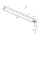
図1は、実施形態に係る照明システムが有するカメラ付き照明装置の外観例を示す斜視図である。図1に示すように、カメラ付き照明装置10aは、照明部20a、撮影部30a、本体部40aを有する。カメラ付き照明装置10aは、本体部40aが天井面へ設置され、照明部20aから出力される光が照射面の一例である床面へ向けて照射される天井直付けタイプの照明装置である。カメラ付き照明装置10aは、例えば工場での生産ラインの監視やオフィス内での従業員の状態監視などの用途で主に屋内で使用される。(Regarding a camera-equipped lighting device applicable to the embodiment)
Fig. 1 is a perspective view showing an example of the appearance of a camera-equipped lighting device included in a lighting system according to an embodiment. As shown in Fig. 1, the camera-equipped
なお、説明を分かりやすくするために、図1には、鉛直下向きを正方向とし、鉛直上向きを負方向とするZ軸を含む3次元の直交座標系を図示している。また、X軸はカメラ付き照明装置10aの長さ方向に、Y軸はカメラ付き照明装置10aの幅方向に、それぞれ沿うように図示している。かかる直交座標系は、後出の説明に用いる他の図面でも示す場合がある。For ease of understanding, FIG. 1 illustrates a three-dimensional Cartesian coordinate system including a Z axis with the positive direction being vertically downward and the negative direction being vertically upward. The X axis is illustrated as running along the length direction of the camera-equipped
照明部20aは、Y軸方向に沿うように配置された、長尺状のシャーシまたは基板(不図示)上に所定の間隔で配置された複数の発光素子(不図示)を有し、シャーシとの間に発光素子が収容されるよう床面側、すなわちZ軸正方向側に拡散カバー21aが設けられた照明バーである。The
拡散カバー21aは、例えば、アクリルやポリカーボネート等の透光性の材料から作られている。拡散カバー21aは、フロスト処理が施されて複数の発光素子から出射される光を拡散する機能を有するようになっている。なお、拡散カバー21aに適宜拡散材や着色剤を混入させてもよい。The
撮影部30aは、遮光カバー31aと、後述するカメラとを有し、照明部20aのX軸負方向側に隣り合うように並んで配置される。The photographing
本体部40aは、照明部20aおよび撮影部30aを保持する。また、本体部40aは、カメラ付き照明装置10aを天井その他の所定の位置に取り付けるための取付部材を兼ねる。The
遮光カバー31aは、本体部40aとの間にカメラを覆うように本体部40aのZ軸正方向側に配設される。また、遮光カバー31aは、カメラのレンズと対向する位置に設けられた貫通口を有する。このような遮光カバー31aを配設することで、照明部20aの拡散カバー21aから照射された光をカメラのレンズに入り込みにくくすることができる。The light-shielding
上述では、カメラ付き照明装置10aが長尺状の照明部20aを有するように説明したが、これはこの例に限定されない。例えば、カメラ付き照明装置10aは、円盤状のシーリングライトであってもよいし、円環状であってもよい。In the above, the camera-equipped
次に、カメラ付き照明装置10aの機能的構成について説明する。図2は、実施形態に係る照明システムが有するカメラ付き照明装置10aの構成の一例を模式的に示すブロック図である。Next, the functional configuration of the camera-equipped
図2に示すように、カメラ付き照明装置10aは、接続部50、本体部40a、照明部20a、撮影部30aを備える。接続部50は、カメラ付き照明装置10aを動作させる各種ケーブルの接続用の端子が配置された端子台である。As shown in FIG. 2, the camera-equipped
本体部40aは、電源部41、制御マイコン42を有する。電源部41は、接続部50を介して交流電源60から供給された交流電力を直流電力に変換して出力する電源回路を有する。交流電源60は、例えば商用電源である。The
また、電源部41は、直流電流を所定の電圧(例えば、50V)で照明部20aへ給電し、後述する発光素子22の点灯を制御する。電源部41は、点灯制御部の一例である。さらに、電源部41は、直流電流を所定の電圧(例えば、5V)に変換し、撮影部30aへ給電する。The power supply unit 41 also supplies direct current at a predetermined voltage (e.g., 50 V) to the
制御マイコン42は、図示されないメモリに予め設定された制御信号を生成し、電源部41、点灯制御部および後述する撮影制御部にそれぞれ出力する処理部である。The control microcomputer 42 is a processing unit that generates control signals that are preset in a memory (not shown) and outputs them to the power supply unit 41, the lighting control unit, and the photography control unit (described later).
照明部20aは、複数の発光素子22を有する。発光素子22は、シャーシ上の配線パターンにそれぞれ接続されており、電源部41から直流出力が供給され、点灯制御部により点灯制御される。発光素子22は、例えばセラミックスで形成された本体に配設されたLED(Light Emitting Diode)チップと、このLEDチップを封止するエポキシ系樹脂やシリコーン樹脂等のモールド用の透光性樹脂とを含む。The
LEDチップは、例えば、青色光を発する青色のLEDチップである。透光性樹脂には、蛍光体が混入されており、白色光を出射できるようにするために、青色の光とは補色の関係にある黄色系の光を放射する黄色蛍光体が使用されている。なお、LEDチップは、例えば赤色光や緑色光、あるいは白色光を発するものであってもよい。また、透光性樹脂は、乳白色を有し、光を拡散させる拡散部材であってもよい。The LED chip is, for example, a blue LED chip that emits blue light. A phosphor is mixed into the translucent resin, and a yellow phosphor that emits yellow light, which is a complementary color to blue light, is used to enable the emission of white light. The LED chip may be one that emits, for example, red light, green light, or white light. The translucent resin may also be a diffusion material that has a milky white color and diffuses light.
また、LEDは、LEDチップを直接照明部20aが有するシャーシまたは基板に実装するようにしてもよく、また、砲弾型のLEDを実装するようにしてもよく、実装方式や形式は、特に限定されるものではない。The LED may be mounted as an LED chip directly on the chassis or substrate of the
撮影部30aは、撮影制御部32およびカメラ33を有する。撮影制御部32は、カメラ33による撮影を制御する。カメラ33は、例えばCCD(Charge Coupled Device)やCMOS(Complementary Metal Oxide Semiconductor)イメージセンサなど、電子的に画像を取得する撮像素子と、レンズとを備え、撮像素子およびレンズ等に応じた所定の画角を撮像する。撮影部30aは、カメラ33で撮像された画像を記録させるための記憶部(図示せず)を有してもよい。The photographing
図3は、実施形態に係る照明システムが有する別のカメラ付き照明装置10bの外観例を示す模式図である。図3に示すカメラ付き照明装置10bは、図1の示したカメラ付き照明装置10aの照明部20aを、カメラ付き照明装置10aの長手方向に縮めたような形状とされ、拡散カバー21bが設けられた照明部20bと、遮光カバー31bが設けられた撮影部30bと、本体部40bとを有する。これらカメラ付き照明装置10bが有する照明部20b、拡散カバー21b、撮影部30b、遮光カバー31bおよび本体部40bの機能および構成は、図1を用いて説明したカメラ付き照明装置10aが有する照明部20a、拡散カバー21a、撮影部30a、遮光カバー31aおよび本体部40aの機能および構成と同等であるので、ここでの詳細な説明を省略する。Figure 3 is a schematic diagram showing an example of the appearance of another camera-equipped
カメラ付き照明装置10bは、本体部40bが例えばアーム部材といった取付部材により、壁面、棚面、机上などに、照明部20bから出力される光が、照射対象の一例である、作業者の手元に向けて照射されるように設置される。カメラ付き照明装置10bは、例えば工場での作業者における作業の監視や、オフィス内での従業員の状態監視などの用途で、主に屋内にて使用される。なお、カメラ付き照明装置10bの形状は、図3に示した形状に限定されない。例えば、カメラ付き照明装置10bは、円盤状、円環状であってもよい。The camera-equipped
(実施形態に係る照明システムについて)
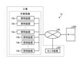
次に、図4Aおよび図4Bを用いて、実施形態に係る照明システムについて説明する。図4Aは、実施形態に係る照明システムの概要を示す図である。なお、以下では、照明システム1aが工場に導入される場合を例に挙げて説明する。(Lighting System According to the Embodiment)
Next, a lighting system according to an embodiment will be described with reference to Fig. 4A and Fig. 4B. Fig. 4A is a diagram showing an overview of the lighting system according to the embodiment. Note that, in the following, a case where the
図4Aに示される、実施形態に係る照明システム1aは、工場あるいは工場を運営する組織の内部で完結するオンプレミスのシステムとして構成される例である。図4Aに示すように、実施形態に係る照明システム1aは、それぞれ複数のカメラ付き照明装置10aおよび10b(図4Aにおいては、共に照明装置と記載)と、管理装置100とを備える。また、図4Aに示す例では、各カメラ付き照明装置10aおよび10bが工場の作業現場(例えば、製造ライン等)に設置される場合を示す。The
管理装置100は、作業現場に設置された各カメラ付き照明装置10aおよび10bを管理する装置である。例えば、管理装置100は、各カメラ付き照明装置10aおよび10bの照明部20aおよび20bそれぞれの照明態様や、撮影部30aおよび30bの撮像向き、倍率等をネットワーク65を介して遠隔で制御する。The
また、管理装置100は、各撮影部30aおよび30bで撮影された画像または映像を収集し、記憶する。例えば、管理装置100によって収集された画像または映像は、作業現場の監視等に用いられる。The
ところで、上述のように、管理装置100には、各撮影部30aおよび30bで撮影された撮影データが集積される。しかしながら、従来においては、管理装置に集積された撮影データを記憶したり、管理者に対して表示したりするに留まっており、生産性の向上などへの適用は、考えられていなかった。As described above, the
そこで、実施形態に係る管理装置100では、カメラ付き照明装置10aで取得される第1の撮影データから撮影現場における異常を検出し、異常が検出された第1の撮影データの箇所と、当該箇所に対応する第2の撮影データの箇所とを関連付ける。実施形態に係る管理装置100は、これにより、生産性の向上への適用を図ることを可能とする。The
なお、以下では、カメラ付き照明装置10aおよび10bによる撮影が行われる撮影現場が作業場である場合について説明する。また、作業場における異常とは、当該作業場においてあるべき状態以外の所定の状態を示す。例えば、作業場に配置される作業者の人数が所定以外の人数であったり、作業場の所定位置に所定量の生産物あるいは部品等が無い場合に、作業場において異常が発生したとする。すなわち、実施形態に係る管理装置100は、例えば、作業場に配置される人数や、所定位置の物品の量などを検出し、検出結果を規定値と比較して異常の有無を検出する。In the following, a case will be described where the shooting site where the camera-equipped
図4Aの例では、実施形態に係る照明システム1aが工場などにおけるオンプレミスのシステムとして構成される例について説明した。実施形態に係る照明システムは、これに限らず、実施形態に係る照明システムは、インターネットなどの外部のネットワークを介して、作業現場と管理装置100と通信を行うように構成することができる。In the example of FIG. 4A, an example has been described in which the
図4Bは、実施形態に係る別の例による照明システムの概要を示す図である。図4Bにおいて、照明システム1bは、工場内の作業現場に設置される各カメラ付き照明装置10aおよび10b(図4Bにおいては、共に照明装置と記載)が、インターネットなどの外部のネットワーク66を介して、サーバ200に接続される。サーバ200は、図4Aに示した管理装置100の機能を含む。ネットワーク66およびサーバ200は、それぞれクラウドネットワークおよびクラウドサーバであってよい。また、図4Bの例では、例えば工場内に設置されるモニタ装置201が、ネットワーク66を介してサーバ200と接続される。FIG. 4B is a diagram showing an overview of a lighting system according to another example of the embodiment. In FIG. 4B, in
なお、上述では、サーバ200が管理装置100の機能を全て含むように説明したが、これはこの例に限定されない。例えば、工場あるいは工場を運営する組織内に管理装置100を設置し、管理装置100の機能のうち一部の機能(学習機能など)をサーバ200に持たせることも可能である。In the above description, the
(実施形態に適用可能なカメラ付き照明装置の設置について)
図5Aおよび図5Bは、実施形態に適用可能な、カメラ付き照明装置10aおよび10bの設置例を示す模式図である。なお、図5Aおよび図5Bの例では、作業場は、所定人数(この例では4人)の人80(以下、作業者80)が作業台72に対して整列して配置される構成を単位としている。図5Aは、作業場を作業者80の整列方向から見た模式図、図5Bは、作業場を作業者80の整列方向に平行な方向から見た模式図をそれぞれ示している。(Installation of a camera-equipped lighting device applicable to the embodiment)
5A and 5B are schematic diagrams showing installation examples of camera-equipped
カメラ付き照明装置10aは、床面71の方向を照射するように、本体部40aにより天井70に取り付けられる。図5Bの例では、カメラ付き照明装置10aは、照明部20aが作業台72と平行、且つ、撮影部30aの撮影対象となる複数の作業者80の全員(この例では4人)が撮影範囲に含まれるような配置で設置される。カメラ付き照明装置10aが設置される高さH(第1の高さ)および位置は、例えば、当該撮影対象となる所定数の作業者80の全員(この例では4人)が整列される整列方向の長さWと、当該カメラ付き照明装置10aの撮像部30aが含むカメラ33の当該整列方向における画角αと、想定される作業者80の頭部の高さhと、に基づき決定することができる。The camera-equipped
また、図5Aおよび図5Bの例では、各作業者80は、床面71に立った状態で作業を行うことが想定されている。したがって、作業台72は、立った状態の作業者80が手元において作業が容易な高さに設けられる。これに限らず、各作業者が椅子などに座った状態で作業を行うようにし、作業台72を対応する高さに設けてもよい。In the examples of Figures 5A and 5B, it is assumed that each
各作業者80に対して、カメラ付き照明装置10bがそれぞれ設置される。カメラ付き照明装置10bは、アーム部材などの取り付け部材74により、壁面、棚、作業台72などに取り付けられる。図5Bの例では、カメラ付き照明装置10bは、取り付け部材74により、作業台72の前面の壁面に取り付けられている。A camera-equipped
カメラ付き照明装置10bは、カメラ付き照明装置10aが設置される高さより低い高さ(第2の高さ)、例えば各作業者80が作業を行う手元を照射する高さおよび配置で設置される。このように設置することで、カメラ付き照明装置10bの撮影部30aは、当該カメラ付き照明装置10bに対応する作業者80の手元をより詳細に撮影可能となる。The camera-equipped
なお、図5Bの例では、カメラ付き照明装置10bが作業者80と1対1の関係で設けられているが、これはこの例に限定されない。複数、例えば2乃至3人の作業者80に対して1台のカメラ付き照明装置10bを設けてもよい。この場合、カメラ付き照明装置10bの撮影部30bで撮影された第2の撮影データによる撮影画像に対し、各作業者80が配置される位置が関連付けられる。In the example of FIG. 5B, the camera-equipped
(実施形態に係る管理装置の詳細)
次に、実施形態に係る管理装置100について、より詳細に説明する。なお、ここでは、図4Aを用いて説明した管理装置100について説明を行う。図4Bを用いて説明したサーバ200は、以下に説明する図4Aの管理装置100と同等の機能を含むものとする。(Details of the Management Device According to the Embodiment)
Next, the
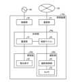
図6は、実施形態に係る管理装置100の機能を説明するための一例の機能ブロック図である。図6に示すように、実施形態に係る管理装置100は、通信部2と、記憶部3と、制御部4とを備える。通信部2は、ネットワーク65を介して各カメラ付き照明装置10aおよび10bとデータ通信を行う通信モジュールである。FIG. 6 is an example functional block diagram for explaining the functions of the
記憶部3は、例えば、フラッシュメモリ等の半導体メモリ素子、または、HDD(Hard Disk Drive)、光ディスク等のデータを不揮発性に記憶可能な記憶装置である。図6示す例において、記憶部3は、撮影データデータベース3a、特定情報データベース3bおよび作業データデータベース3cを有する。The storage unit 3 is, for example, a semiconductor memory element such as a flash memory, or a storage device capable of non-volatilely storing data such as a hard disk drive (HDD) or an optical disk. In the example shown in FIG. 6, the storage unit 3 has a shooting data database 3a, a
撮影データデータベース3aは、各カメラ付き照明装置10aおよび10bで撮影された撮影データを記憶するデータベースである。The photography data database 3a is a database that stores photography data captured by each of the camera-equipped
特定情報データベース3bは、作業場における異常を検出するための特定情報を格納するデータベースである。特定情報の一例として、作業場の所定領域に配置される人数、作業場において生産物や部品などが収容される所定位置の状態を示すデータ、これら生産物や部品などの形状を示すデータ、各作業者80の作業に係る動作を示すデータ、等が挙げられる。特定情報のうち少なくとも一部の情報は、例えば、後述する学習部4fによって生成されてよい。The
作業データデータベース3cは、各製造ラインの作業効率に関する情報を記憶するデータベースである。例えば、作業効率に関する情報は、後述する測定部4eによって生成される。The work data database 3c is a database that stores information about the work efficiency of each production line. For example, the information about the work efficiency is generated by the measurement unit 4e, which will be described later.
次に、制御部4について説明する。制御部4は、例えば、CPU(Central Processing Unit)、ROM(Read Only Memory)、RAM(Random Access Memory)、入出力ポートなどを有するマイクロコンピュータや各種の回路を含む。Next, the control unit 4 will be described. The control unit 4 includes, for example, a microcomputer having a CPU (Central Processing Unit), ROM (Read Only Memory), RAM (Random Access Memory), input/output ports, and various other circuits.
図6に示す例では、制御部4は、取得部4aと、検出部4bと、タグ付け部4cと、再生部4dと、測定部4eと、学習部4fと、通知部4gとを含む。取得部4a、検出部4b、タグ付け部4c、再生部4d、測定部4e、学習部4fおよび通知部4gの機能は、例えば、制御部4のCPUが制御部4のRAM、ROM、または記憶部3に記憶されているプログラムを読み出して実行することにより実現される。6, the control unit 4 includes an acquisition unit 4a, a detection unit 4b, a tagging unit 4c, a playback unit 4d, a measurement unit 4e, a
なお、取得部4a、検出部4b、タグ付け部4c、再生部4d、測定部4e、学習部4fおよび通知部4gは、それぞれ一部または全部がASIC(Application Specific Integrated Circuit)やFPGA(Field Programmable Gate Array)等のハードウェアで構成されてもよい。The acquisition unit 4a, detection unit 4b, tagging unit 4c, playback unit 4d, measurement unit 4e, learning
取得部4aは、カメラ付き照明装置10aが備える撮影部30aにより作業現場が撮影された第1の撮影データと、カメラ付き照明装置10bが備える撮影部30bにより作業現場が撮影された第2の撮影データと、を取得する。例えば、取得部4aは、リアルタイムで各撮影部30aおよび30bから第1および第2の撮影データを取得し、取得した第1および第2の撮影データを、それぞれ取得毎に撮影データデータベース3aに格納する。The acquisition unit 4a acquires first image data of the work site captured by the
このとき、例えば1台のカメラ付き照明装置10aにより撮影された第1の撮影データと、当該カメラ付き照明装置10aの撮影範囲に含まれる所定人数の作業者80それぞれに対応する各カメラ付き照明装置10bにより撮影された第2の撮影データそれぞれと、を関連付けて撮影データデータベース3aに格納することができる。このように、第1の撮影データと、第1の撮影データに関連する第2の撮影データとを関連付けて撮影データデータベース3aに格納することで、作業内容の振り返りや検証が容易となり、作業効率の改善に繋げることができる。At this time, for example, the first photographed data captured by one camera-equipped
なお、製造ラインが複数ある場合、製造ライン毎に第1の映像データと第2の映像データとを関連付けて、順次、撮影データデータベース3aに格納する。When there are multiple production lines, the first video data and the second video data are associated with each other for each production line and stored sequentially in the shooting data database 3a.
検出部4bは、取得部4aによって取得された第1および第2の撮影データと、特定情報とに基づき、作業場(撮影現場)の状態を検出する。ここで、作業場の状態は、作業場における異常を含む。ここで、上述のように、「作業場における異常」とは、例えば、作業場に配置される作業者の人数が所定以外の人数であったり、作業場の所定位置に所定量の生産物あるいは部品等が無い等の、当該作業場においてあるべき状態以外の所定の状態を示してよい。The detection unit 4b detects the state of the workplace (shooting site) based on the first and second shooting data acquired by the acquisition unit 4a and the specific information. Here, the state of the workplace includes an abnormality in the workplace. Here, as described above, "abnormality in the workplace" may indicate a predetermined state other than the state that the workplace should be in, such as, for example, the number of workers assigned to the workplace being other than the predetermined number, or the absence of a predetermined amount of products or parts, etc. in a predetermined position in the workplace.
例えば、検出部4bは、取得部4aによって取得された、カメラ付き照明装置10aの撮影部30aにより撮影された第1の撮影データに対して画像解析を行い、第1の撮影データによる撮影範囲に含まれる人を認識することができる。検出部4bは、例えば、認識された人の数が所定人数以外の場合に、異常を検出する。For example, the detection unit 4b performs image analysis on the first shooting data captured by the
また例えば、検出部4bは、第1の撮影データに対する画像解析により、第1の撮影データによる撮影範囲の所定位置にある物品を認識することができる。検出部4bは、学習部4fにおいて学習されたモデルを用いて人や物品の認識を実行することができる。これに限らず、検出部4bは、第1の撮影データに対してパターンマッチングなどを用いて人や物品の認識を行ってもよい。検出部4bは、例えば、認識された物品の量が所定量あるいは予測される量と異なる場合に、異常を検出する。For example, the detection unit 4b can recognize an object at a predetermined position in the shooting range of the first shooting data by image analysis of the first shooting data. The detection unit 4b can recognize people and objects using a model learned by the
さらに、検出部4bは、取得部4aにより取得されたカメラ付き照明装置10bの撮影部30bにより撮影された第2の撮影データに対して画像解析を行い、第2の撮影データによる撮影範囲に含まれる人の認識を行い、認識された人の動作を認識することができる。検出部4bは、認識された動作に基づき、その動作が正常か否かを検出することができる。Furthermore, the detection unit 4b performs image analysis on the second shooting data captured by the
タグ付け部4cは、検出部4bによって第1の撮影データに基づき異常が検出された場合に、第1の撮影データの当該異常が検出された箇所(異常検出箇所)に異常に関する異常情報をタグ付けする。例えば、異常情報はフラグであり、第1の撮影データの異常が検出されたフレームのフラグを「1」とし、異常が検出されないフレームのフラグを「0」とすることができる。When an abnormality is detected by the detection unit 4b based on the first photographed data, the tagging unit 4c tags the location in the first photographed data where the abnormality was detected (the abnormality detection location) with abnormality information related to the abnormality. For example, the abnormality information is a flag, and the flag of a frame in which an abnormality is detected in the first photographed data can be set to "1" and the flag of a frame in which no abnormality is detected can be set to "0."
また、タグ付け部4cは、検出部4bによって第1の撮影データに基づき異常が検出された場合に、第1の撮影データの当該異常が検出された箇所に対応する第2の撮影データの箇所に、タグ付を行うことができる。これにより、第1の撮影データと第2の撮影データとの間で異常情報に基づく関連付けが行われ、第1の撮影データにおいて検出された異常に対応する、第2の映像データの内容を容易に確認でき、作業の振り返りや検証を効率的に実行可能となる。In addition, when an abnormality is detected based on the first shooting data by the detection unit 4b, the tagging unit 4c can tag a location in the second shooting data that corresponds to the location in the first shooting data where the abnormality was detected. This allows the first shooting data and the second shooting data to be associated based on the abnormality information, making it easy to check the contents of the second video data that correspond to the abnormality detected in the first shooting data, and making it possible to efficiently review and verify the work.
再生部4dは、タグ付け部4cによって異常情報がタグ付けされた第1の撮影データを切り取って再生することができる。すなわち、再生部4dは、撮影データデータベース3aから異常情報がタグ付けされた第1の撮影データを抽出し、再生する。また、再生部4dは、同様にして、タグ付け部4cによって第1の撮影データの異常検出箇所に対応した箇所にタグ付けされた第2の撮影データを切り取って再生することもできる。The playback unit 4d can cut out and play back the first shooting data tagged with abnormality information by the tagging unit 4c. That is, the playback unit 4d extracts the first shooting data tagged with abnormality information from the shooting data database 3a and plays it back. Similarly, the playback unit 4d can also cut out and play back the second shooting data tagged by the tagging unit 4c at a location corresponding to the location where the abnormality was detected in the first shooting data.
そして、再生部4dは、撮影時刻を表示しつつ、第1の撮影データや第2の撮影データの再生を行う。これにより、第1の撮影データについては異常の状態を示す箇所のみを再生することができるので、異常の状態を用意に把握することが可能となる。また、第2の撮影データについては、第1の撮影データに基づき検出された異常に対応する箇所のみを再生することができるので、異常の状態をより詳細に把握することが可能となる。The playback unit 4d then plays back the first and second shooting data while displaying the shooting time. This allows only the parts of the first shooting data that indicate an abnormal state to be played back, making it possible to easily grasp the abnormal state. Also, for the second shooting data, only the parts that correspond to the abnormality detected based on the first shooting data can be played back, making it possible to grasp the abnormal state in more detail.
なお、この際には、例えば、異常を検出した時刻を基準として前後所定期間(例えば、前後1分間)を併せて再生することが好ましい。In this case, it is preferable to play back a predetermined period (e.g., one minute before and after) based on the time when the abnormality was detected.
測定部4eは、第1の撮影データあるいは第2の撮影データに基づき、各種の測定を行う。The measurement unit 4e performs various measurements based on the first shooting data or the second shooting data.
測定部4eは、例えば、第2の撮影データから、各作業者80の単位時間当たりの作業効率を測定することができる。より具体的には、測定部4eは、例えば検出部4bにより第2の撮影データそれぞれに基づき認識された、第2の撮影データそれぞれに対応する各作業者80の動作に基づき、各作業者80による作業のタクトタイム(動作間隔)をそれぞれ測定することができる。また、測定部4eは、第1の撮影データから、当該第1の撮影データの撮影範囲に含まれる所定人数の作業者80それぞれの動きの時間間隔等を測定することも可能である。これらの測定結果は、例えば、作業管理者による各作業者80の配置転換の検討を容易にするために用いることができる。The measurement unit 4e can measure, for example, the work efficiency per unit time of each
学習部4fは、例えば、過去の第2の撮影データから、当該第2の撮影データに対応する作業者80について、上述した作業者80の作業動作を学習し、モデルを生成、更新することができる。例えば、学習部4fは、作業者80の正常な作業動作を教師データとする機械学習によって、モデルを生成する。学習部4fは、このようなモデルを、作業者80毎に生成する。検出部4bは、このモデルに基づき、各作業者80の動作の異常を検出することができる。The
また例えば、学習部4fは、過去の第1の撮影データから、当該第1の撮影データの撮影範囲に含まれる所定位置における生産物や部品などの物品、および、その物品の増減速度などを学習し、モデルを生成、更新することができる。検出部4bは、このモデルに基づき、生産物や物品に関する異常を検出することができる。For example, the
なお、図4Aに示した構成において、学習部4fの構成を管理装置100とは別の装置(例えば、クラウドネットワーク)に設けることにしてもよい。In the configuration shown in FIG. 4A, the
通知部4gは、検出部4bによって異常が検出された場合に、作業者あるいは作業管理者に通知する。すなわち、管理装置100では、即時的に異常の発生を通知する。例えば、通知部4gは、検出された異常に対応するカメラ付き照明装置10bにおける照明部20bの照明態様を変更することで、当該カメラ付き照明装置10bに対応する作業者80に対して異常を通知することができる。When an abnormality is detected by the detection unit 4b, the
ここで、照明態様とは、例えば照明を駆動する周波数や、照明の照度を含む。さらには、照明態様の変更を、照明の点滅、色温度の変更などにより実現することも可能である。この場合において、照明態様の変更によって作業をストップさせてしまうと、作業効率の低下を招くため、作業に支障が出ない範囲で照明態様を変更することが好ましい。Here, the lighting mode includes, for example, the frequency at which the lighting is driven and the illuminance of the lighting. Furthermore, it is also possible to change the lighting mode by turning the lighting on and off, changing the color temperature, etc. In this case, if work is stopped due to a change in the lighting mode, this will lead to a decrease in work efficiency, so it is preferable to change the lighting mode within a range that does not interfere with work.
これに限らず、通知部4gは、この通知を、作業場内のスピーカによる音出力や、パトランプなどにより異常を作業者80に通知するようにしてもよい。また、通知部4gは、検出された異常に対応するカメラ付き照明装置10aにおける照明部20aの照明態様を変化させることもできる。In addition, the
(実施形態に係る異常検出の具体例)
次に、実施形態に係る異常検出について、より具体的に説明する。(Specific example of abnormality detection according to the embodiment)
Next, abnormality detection according to the embodiment will be described in more detail.
・第1の具体例
先ず、第1の具体例として、カメラ付き照明装置10aの撮影部30aにより撮影された第1の撮影データを用いた異常検出の例について説明する。第1の具体例では、管理装置100は、第1の撮影データから、撮影部30aによる撮影範囲内の所定領域に含まれる人(作業者80)を認識し、認識された人数を測定する。管理装置100は、測定された人数が所定人数以外の場合に、通知を出力する。First Specific Example First, as a first specific example, an example of abnormality detection using first image data captured by the
図7Aおよび図7Bは、第1の撮影データにより撮影された撮影画像を模式的に示す図である。図7Aおよび図7Bにおいて、作業台72の直近の所定領域75は、4人の作業者80が含まれる状態が正常な状態であるものとする。すなわち、この場合、所定領域75における所定人数は、4人である。Figures 7A and 7B are schematic diagrams showing images captured using the first shooting data. In Figures 7A and 7B, the normal state of the predetermined
管理装置100において、検出部4bは、取得部4aによりカメラ付き照明装置10aの撮影部30aから取得された第1の撮影データから、所定領域75に含まれる各作業者801~804を認識し、認識された人数を計数する。図7Aの例では、所定領域75において4人の作業者801~804が認識されているので、検出部4bは、異常が無いとする。 In the
これに対して、図7Bの例では、所定領域75に上述の作業者801~804に加えて作業者805が含まれており、検出部4bは、所定領域において5人の作業者801~805を認識する。この場合、所定領域75には、所定人数の4人を超える作業者801~805が含まれているため、検出部4bは、異常を検出する。例えば、図7Bの例では、作業者804の作業においてトラブル等が発生し、その対応に作業者805が呼ばれた状況などが考えられる。通知部4gは、検出部4bにおける異常の検出に応じて、例えば作業管理者への通知を行う。 In contrast, in the example of Fig. 7B, the
このように、カメラ付き照明装置10aの撮影部30aにより撮影された第1の撮影データに基づき撮影現場の異常を検出することで、トラブル等に対して迅速且つ適切の対応することができ、生産性の改善が可能である。In this way, by detecting abnormalities at the shooting site based on the first shooting data captured by the
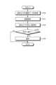
図8は、実施形態に係る、第1の撮影データを用いた異常検出処理を示す一例のフローチャートである。なお、図8において、カメラ付き照明装置10aを「高所カメラ」として示している。また、図8のフローチャートによる処理は、所定周期(例えば第1の撮影データのフレーム周期)で繰り返されて実行される。Figure 8 is a flowchart showing an example of an anomaly detection process using the first shooting data according to the embodiment. In Figure 8, the camera-equipped
ステップS100で、管理装置100は、取得部4aにより、高所カメラ(カメラ付き照明装置10a)の撮影部30aで撮影された第1の撮影データを取得する。次のステップS101で、管理装置100は、検出部4bにより、ステップS100で取得部4aにより取得された第1の撮影データに対して画像解析を行い、第1の撮影データによる撮影画像に含まれる人を認識する。次のステップS102で、管理装置100は、検出部4bにより、撮像画像における検出エリア(所定領域75)内で認識された人数を測定する。In step S100, the
次のステップS103で、管理装置100は、検出部4bにより、ステップS102で測定された人数が所定人数か否かを判定する。管理装置100は、測定された人数が所定人数であると判定した場合(ステップS103、「Yes」)、図8のフローチャートによる一連の処理を終了させる。In the next step S103, the
一方、管理装置100は、測定された人数が所定人数ではない(所定人数を超える人数、あるいは、所定人数未満の人数)と判定した場合(ステップS103、「No」)、処理をステップS104に移行させ、通知部4gにより通知を出力する。On the other hand, if the
・第2の具体例
次に、実施形態に係る異常検出の第2の具体例について説明する。第2の具体例は、カメラ付き照明装置10aとカメラ付き照明装置10bとを連携させる例である。Second Specific Example Next, a second specific example of anomaly detection according to the embodiment will be described. The second specific example is an example in which the camera-equipped
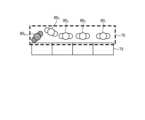
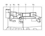
図9Aは、カメラ付き照明装置10aの撮影部30aにより撮影された第1の撮影データによる撮影画像300の例を示す模式図である。図9Aに示されるように、撮影画像300は、複数の作業者8010、8011および8012が作業台72に向かって作業を行っている様子が含まれる。また、撮影画像300において、棚部76は、例えば、各作業者8010~8012の作業により生産された生産物、あるいは、生産に用いる部品等を載置するために設けられている。 Fig. 9A is a schematic diagram showing an example of a captured
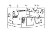
図9Bは、カメラ付き照明装置10bの撮影部30bにより撮影された第2の撮影データによる撮影画像301の例を示す模式図である。図9Bの例では、撮影部30bは、例えば図9Aに示す各作業者8010~8012のうち左端側の作業者8010を撮影対象としている。 Fig. 9B is a schematic diagram showing an example of a captured
第2の具体例では、管理装置100は、例えば、検出部4bにより第1の撮影データに基づき異常が検出された場合、タグ付け部4cにより、第1の撮影データの異常が検出された箇所(フレームあるいは時刻)にタグ付けを行う。それと共に、タグ付け部4cは、第2の撮影データの、第1の撮影データの異常が検出された箇所に対応する箇所(フレームあるいは時刻)にタグ付けを行う。In the second specific example, in the
このとき、タグ付け部4cは、第1の撮影データによる撮影画像300において異常が検出された位置に対応するカメラ付き照明装置10bの撮影部30bにより撮影された第2の撮影データの当該箇所に、タグ付けを行う。これに限らず、タグ付け部4cは、撮影画像300に関連する全てのカメラ付き照明装置10bの撮影部30bにより撮影された各第2の撮影データの当該箇所にタグ付けを行ってもよい。At this time, the tagging unit 4c tags the location of the second photographed data captured by the photographing
これに限らず、管理装置100は、第2の撮影データに基づき異常が検出された場合に、第2の撮影データの異常が検出された箇所にタグ付けを行うと共に、第1の撮影データの、第2の撮影データの異常が検出された箇所に対応する箇所にタグ付けを行うこともできる。Not limited to this, when an abnormality is detected based on the second photographed data, the
このように、第1の撮影データと第2の撮影データとで、異常が検出された箇所(フレームあるいは時刻)をタグ付けにより関連付けることで、作業内容の振り返りや検証が容易となり、作業効率の改善に繋げることができる。In this way, by tagging and associating the locations (frames or times) where abnormalities were detected in the first and second shooting data, it becomes easier to review and verify the work content, which can lead to improved work efficiency.
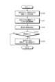
図10は、実施形態に係る、第1の撮影データおよび第2の撮影データを用いた異常検出処理を示す一例のフローチャートである。なお、図10において、カメラ付き照明装置10aを「高所カメラ」、カメラ付き照明装置10bを「低所カメラ」としてそれぞれ示している。また、図10のフローチャートによる処理は、所定周期(例えば第1の撮影データのフレーム周期)で繰り返されて実行される。Figure 10 is a flowchart showing an example of an anomaly detection process using the first and second shooting data according to an embodiment. In Figure 10, the camera-equipped
ステップS120で、管理装置100は、取得部4aにより、高所カメラ(カメラ付き照明装置10a)の撮影部30aで撮影された第1の撮影データと、低所カメラ(カメラ付き照明装置10b)の撮影部30bで撮影された第2の撮影データと、を取得する。次のステップS121で、管理装置100は、検出部4bにより、ステップS120で取得部4aにより取得された第1の撮影データに対して画像解析を行う。次のステップS122で、管理装置100は、検出部4bにより、第1の撮影データに基づき異常の有無を検出する。In step S120, the
次のステップS123で、管理装置100は、検出部4bにより、ステップS122で異常が検出されたかを判定する。管理装置100は、異常が検出されなかったと判定した場合(ステップS123、「No」)、図10のフローチャートによる一連の処理を終了させる。In the next step S123, the
一方、管理装置100は、異常が検出されたと判定した場合(ステップS123、「Yes」)、処理をステップS124に移行させる。ステップS124で、管理装置100は、タグ付け部4cにより、ステップS120で取得された第2の撮影データの、第1の撮影データの異常が検出された箇所に対応する箇所(フレームあるいは時刻)にタグ付けを行う。これにより、管理装置100は、第1の撮影データに基づき検出された異常を、第2の撮影データに対して関連付けることができ、カメラ付き照明装置10aとカメラ付き照明装置10bとを連携させることができる。On the other hand, if the
より具体的な例を用いて説明する。上述した図7Aおよび図7Bを参照し、管理装置100は、検出部4bにより、第1の撮影データに基づき、所定領域75に所定人数(この例では4人)を超える5人の作業者801~805が含まれ、異常が検出されたものとする(図10のステップS123、「Yes」)。この場合、管理装置100は、タグ付け部4cにより、第2の撮影データの、第1の撮影データの異常が検出された箇所に対応する箇所にタグ付けを行う。これにより、第1の撮影データに基づき検出された異常が、第2の撮影データに対して関連付けられる。 A more specific example will be described. With reference to Fig. 7A and Fig. 7B described above, the
例えば、作業管理者は、第2の撮影データのタグ付けされた箇所を含めた所定時間範囲の撮影画像を確認することで、異常の原因を容易に検証することが可能となる。For example, the work manager can easily verify the cause of the abnormality by checking the images captured within a specified time range that includes the tagged area of the second captured data.
別の例として、管理装置100は、検出部4bにより、第1の撮影データに基づき、所定領域75に所定人数(この例では4人)未満の例えば3人の作業者801~803が含まれ、異常が検出されたものとする(図10のステップS123、「Yes」)。すなわちこの場合には、所定領域75内に居るべき作業者804が所定領域75内に居ないことを示している。管理装置100は、タグ付け部4cにより、例えば当該作業者804に対応するカメラ付き照明装置10bの撮影部30bにより撮影された第2の撮影データの、第1の撮影データの異常が検出された箇所に対応する箇所にタグ付けを行う。この第2の撮影データのタグ付けされた箇所を中心に第2の撮影データの再生を行うことで、当該作業者804が居るべき場所に居ない原因(作業に必要な部品の供給が途絶えた、など)を検証することができる。 As another example, the
図10のフローチャートの処理において、ステップS124の処理の代わりに、あるいは、ステップS124の処理に加えて、第1の撮影データに基づき検出された異常を、当該異常に対応するカメラ付き照明装置10bを用いて通知することができる。この通知は、例えば、カメラ付き照明装置10bの照明部20bによる照明態様を変化させることで行うことができる。In the process of the flowchart in FIG. 10, instead of or in addition to the process of step S124, an abnormality detected based on the first photographed data can be notified using the camera-equipped
一例として、図9Aおよび図9Bを参照し、作業者8012が所定時刻(所定時間帯)に、所定量の生産物を纏めて棚部76に載置するように定められている場合について考える。この場合において、検出部4bは、カメラ付き照明装置10aの撮影部30aにより撮影された第1の撮影データに基づき棚部76に当該所定量の生産物が認識されなかった場合、異常を検出したと見做す(図10のステップS123、「Yes」)。そして、管理装置100は、通知部4gにより、作業者8012に対応するカメラ付き照明装置10bの照明部20bによる照明態様を変化(例えば点滅)させる。これにより、カメラ付き照明装置10aとカメラ付き照明装置10bとが連携される。作業者8012は、自身が生産物を棚部76に載置する作業を忘れていたことに気付くことができ、生産性が向上される。 As an example, referring to Fig. 9A and Fig. 9B, consider a case where the
別の例として、図9Aおよび図9Bを参照し、棚部76における部品の在庫量が所定以下あるいは過剰になった場合に、カメラ付き照明装置10bの照明部20bの照明態様を変化させて、各作業者8010~8012に対し、その旨を通知することができる。 As another example, referring to Figures 9A and 9B, when the inventory amount of parts on
例えば、管理装置100は、検出部4bにより、カメラ付き照明装置10aの撮影部30aにより撮影された第1の撮影データに基づき棚部76にストックされる部品を認識する。管理装置100は、測定部4eにより、認識された部品の増減の速度を測定し、測定された増減速度と、現在の棚部76における部品の在庫量とに基づき、当該在庫量が0になる、あるいは、棚部76の収容能力を超えると予測される時間を算出する。管理装置100は、検出部4bにより、算出された時間が所定時間以下であれば、異常が検出されたと見做す(図10のステップS123、「Yes」)。そして、管理装置100は、通知部4gにより、例えば各作業者8010~8012に対応するカメラ付き照明装置10bそれぞれの照明部20bによる照明態様を変化(例えば点滅)させる。これにより、カメラ付き照明装置10aとカメラ付き照明装置10bとが連携される。各作業者8010~8012は、例えば部品の補充要求や補充停止の要求を適切に出すことができ、生産性が向上される。 For example, the
この例では、異常の検出に応じてカメラ付き照明装置10bの照明部20bによる照明態様を変化させているが、これはこの例に限定されない。すなわち、管理装置100は、通知部4gにより、カメラ付き照明装置10aの照明部20aの照明態様を変化させることで、これにより、第1の撮影データと第2の撮影データとを連携させ、検出された異常の各作業者8010~8012に対する通知を行ってもよい。 In this example, the lighting mode of the
また、上述では、カメラ付き照明装置10aの撮影部30aにより撮影された第1の撮影データに基づき検出された異常に応じて通知を行っているが、これはこの例に限定されない。例えば、実施形態に係る照明システム1aは、当該第1の撮影データと、カメラ付き照明装置10bの撮影部30bにより撮影された第2の撮影データと、のうち少なくとも一方に基づき異常が検出された場合に、通知を行うようにしてもよい。In the above description, a notification is given in response to an abnormality detected based on the first photographed data captured by the photographing
・別の具体例
次に、実施形態に適用可能な、異常検出の別の具体例について説明する。上述の第1の具体例では、第1の高さに設置されるカメラ付き照明装置10aの撮影部30aで撮影された第1の撮影データに基づき異常検出を行う例について説明した。また、第2の具体例では、カメラ付き照明装置10aと、第1の高さより低い第2の高さに設置されるカメラ付き照明装置10bとを連携させて、異常検出および通知を行う例について説明した。Another specific example Next, another specific example of abnormality detection that can be applied to the embodiment will be described. In the above-mentioned first specific example, an example of abnormality detection based on first photographed data photographed by the photographing
本実施形態では、これらに限定されず、カメラ付き照明装置10aとカメラ付き照明装置10bとで、それぞれ独立して異常検出を行うことも可能である。In this embodiment, the present invention is not limited to these, and it is also possible for the camera-equipped
例えば、図7Aおよび図7Bを参照し、管理装置100は、カメラ付き照明装置10aの撮影部30aにより撮影された第1の撮影データに基づき所定領域75内の人数や各作業者801~804間の距離をそれぞれ測定する。管理装置100は、検出部4bにより、例えば測定された距離が所定距離より短い場合に、異常を検出する。それと共に、管理装置100は、カメラ付き照明装置10bの撮影部30bにより撮影された第2の撮影データに基づき各作業者801~804の動作について、異常の検出やタクトタイムの測定を行う。異常が検出された場合の通知は、作業管理者に対して行ってもよいし、カメラ付き照明装置10aの照明部20aや、カメラ付き照明装置10bの照明部20bによる照明態様を変化させることで行ってもよい。 For example, referring to Fig. 7A and Fig. 7B, the
なお、上述した実施形態では、照明システム1aまたは1bが工場に設置される場合について説明したが、これに限定されるものではない。すなわち、照明システム1aまたは1bをオフィスや病院など、その他の場所に設置することにしてもよい。In the above-described embodiment, the
本発明の実施形態を説明したが、この実施形態は、例として提示したものであり、発明の範囲を限定することは意図していない。この実施形態は、その他の様々な形態で実施されることが可能であり、発明の要旨を逸脱しない範囲で、種々の省略、置き換え、変更を行うことができる。この実施形態やその変形は、発明の範囲や要旨に含まれると同様に、特許請求の範囲に記載された発明とその均等の範囲に含まれるものである。Although an embodiment of the present invention has been described, this embodiment is presented as an example and is not intended to limit the scope of the invention. This embodiment can be implemented in various other forms, and various omissions, substitutions, and modifications can be made without departing from the gist of the invention. This embodiment and its variations are within the scope of the invention and its equivalents as described in the claims, as well as the scope and gist of the invention.
1a,1b 照明システム
4 制御部
4a 取得部
4b 検出部
4c タグ付け部
4d 再生部
4e 測定部
4f 学習部
4g 通知部
10a,10b カメラ付き照明装置
20a,20b 照明部
30a,30b 撮影部
40a,40b 本体部
70 天井
71 床面
72 作業台
75 所定領域
76 棚部
80,801,802,803,804,805,8010,8011,8012
100 管理装置
100 Management device
Claims (2)
Translated fromJapanese第2の照明部と第2の撮影部とを具備し、前記第1の高さと異なる第2の高さに設置される第2のカメラ付き照明装置と、
前記第1の撮影部および前記第2の撮影部のうち少なくとも一方により撮影された撮影範囲における状態を検出する検出部と、
前記検出部により検出された前記状態に応じて、前記第1のカメラ付き照明装置と、前記第2のカメラ付き照明装置とを連携させて所定の制御を行う制御部と、
を具備し、
前記第1の高さは、前記第1の撮影部に撮影された撮影範囲における所定領域に配置される人の全員が含まれる高さであり、
前記第2の高さは、前記人に想定される手元に対応する高さである
管理装置と、
を含む照明システム。 a first camera-equipped lighting device having a first lighting unit and a first photographing unit and installed at a first height;
a second camera-equipped lighting device including a second lighting unit and a second photographing unit and installed at a second height different from the first height;
a detection unit that detects a state in a photographing range photographed by at least one of the first photographing unit and the second photographing unit;
a control unit that performs a predetermined control by coordinating the first camera-equipped lighting device and the second camera-equipped lighting device in accordance with the state detected by the detection unit;
Equipped with
the first height is a height that includes all people located in a predetermined area in an imaging range photographed by the first imaging unit,
The second height corresponds to an expected hand of the person.
A management device;
A lighting system including:
第2の照明部と第2の撮影部とを具備し、前記第1の高さと異なる第2の高さに設置される第2のカメラ付き照明装置と、
前記第1の撮影部および前記第2の撮影部のうち少なくとも一方により撮影された撮影範囲における状態を検出する検出部と、
前記検出部により検出された前記状態に応じて、前記第1のカメラ付き照明装置と、前記第2のカメラ付き照明装置とを連携させて所定の制御を行う制御部と、
を具備し、
前記制御部は、
前記検出部により検出された前記撮影範囲に含まれる撮影対象の状態に基づき、前記撮影対象の動作間隔を測定する
管理装置と、
を含む照明システム。 a first camera-equipped lighting device having a first lighting unit and a first photographing unit and installed at a first height;
a second camera-equipped lighting device including a second lighting unit and a second photographing unit and installed at a second height different from the first height;
a detection unit that detects a state in a photographing range photographed by at least one of the first photographing unit and the second photographing unit;
a control unit that performs a predetermined control by coordinating the first camera-equipped lighting device and the second camera-equipped lighting device in accordance with the state detected by the detection unit;
Equipped with
The control unit is
a management devicethat measures a motion interval of the object to be photographed based on a state of the object to be photographed included in the photographing range detected by the detection unit ;
A lighting system including:
Priority Applications (2)
| Application Number | Priority Date | Filing Date | Title |
|---|---|---|---|
| JP2020163609AJP7505351B2 (en) | 2020-09-29 | 2020-09-29 | Lighting System |
| JP2024091978AJP7727900B2 (en) | 2020-09-29 | 2024-06-06 | lighting system |
Applications Claiming Priority (1)
| Application Number | Priority Date | Filing Date | Title |
|---|---|---|---|
| JP2020163609AJP7505351B2 (en) | 2020-09-29 | 2020-09-29 | Lighting System |
Related Child Applications (1)
| Application Number | Title | Priority Date | Filing Date |
|---|---|---|---|
| JP2024091978ADivisionJP7727900B2 (en) | 2020-09-29 | 2024-06-06 | lighting system |
Publications (2)
| Publication Number | Publication Date |
|---|---|
| JP2022055906A JP2022055906A (en) | 2022-04-08 |
| JP7505351B2true JP7505351B2 (en) | 2024-06-25 |
Family
ID=80998379
Family Applications (2)
| Application Number | Title | Priority Date | Filing Date |
|---|---|---|---|
| JP2020163609AActiveJP7505351B2 (en) | 2020-09-29 | 2020-09-29 | Lighting System |
| JP2024091978AActiveJP7727900B2 (en) | 2020-09-29 | 2024-06-06 | lighting system |
Family Applications After (1)
| Application Number | Title | Priority Date | Filing Date |
|---|---|---|---|
| JP2024091978AActiveJP7727900B2 (en) | 2020-09-29 | 2024-06-06 | lighting system |
Country Status (1)
| Country | Link |
|---|---|
| JP (2) | JP7505351B2 (en) |
Citations (2)
| Publication number | Priority date | Publication date | Assignee | Title |
|---|---|---|---|---|
| JP2017199519A (en) | 2016-04-26 | 2017-11-02 | パナソニックIpマネジメント株式会社 | Lighting device and lighting system |
| JP2018066628A (en) | 2016-10-19 | 2018-04-26 | ソリッドビジョン株式会社 | Image processing system and image processing method |
Family Cites Families (6)
| Publication number | Priority date | Publication date | Assignee | Title |
|---|---|---|---|---|
| JPH06191319A (en)* | 1992-12-24 | 1994-07-12 | Toyota Motor Corp | Travel control device for vehicle |
| JP2011081521A (en) | 2009-10-06 | 2011-04-21 | Funai Electric Co Ltd | Security device and security system |
| JP6535620B2 (en) | 2016-03-07 | 2019-06-26 | ヤンマー株式会社 | Moving vehicle |
| US10467509B2 (en) | 2017-02-14 | 2019-11-05 | Microsoft Technology Licensing, Llc | Computationally-efficient human-identifying smart assistant computer |
| JP6954133B2 (en) | 2018-01-12 | 2021-10-27 | コニカミノルタ株式会社 | Production control system and production control program |
| JP2020118167A (en) | 2019-01-18 | 2020-08-06 | 中国電力株式会社 | Monitoring device |
- 2020
- 2020-09-29JPJP2020163609Apatent/JP7505351B2/enactiveActive
- 2024
- 2024-06-06JPJP2024091978Apatent/JP7727900B2/enactiveActive
Patent Citations (2)
| Publication number | Priority date | Publication date | Assignee | Title |
|---|---|---|---|---|
| JP2017199519A (en) | 2016-04-26 | 2017-11-02 | パナソニックIpマネジメント株式会社 | Lighting device and lighting system |
| JP2018066628A (en) | 2016-10-19 | 2018-04-26 | ソリッドビジョン株式会社 | Image processing system and image processing method |
Also Published As
| Publication number | Publication date |
|---|---|
| JP7727900B2 (en) | 2025-08-22 |
| JP2024107158A (en) | 2024-08-08 |
| JP2022055906A (en) | 2022-04-08 |
Similar Documents
| Publication | Publication Date | Title |
|---|---|---|
| EP3368953B1 (en) | Commissioning of a sensor system | |
| US20190379804A1 (en) | Symbology reader with multi-core processor | |
| JP6610348B2 (en) | Management program, management apparatus, and management method | |
| CN103714307B (en) | Symbol reader with multi-core processor and operating system and method thereof | |
| JP6473996B2 (en) | Worker management system | |
| CN1983488A (en) | Sensor device | |
| TWI258583B (en) | Device and method for optical detection of printed circuit board | |
| JP7505351B2 (en) | Lighting System | |
| JP2020507854A (en) | Image analysis techniques | |
| JP7404911B2 (en) | management device | |
| CN110191256A (en) | Image sensor with a plurality of pixels | |
| US10552111B2 (en) | Control device | |
| TWI680676B (en) | Webcam apparatus and monitoring system | |
| JP2022055399A (en) | Illumination system and management device | |
| JP7533133B2 (en) | Information processing device, lighting device, and lighting system | |
| JP2023049948A (en) | Management system | |
| US20190356866A1 (en) | Frame Stitching And Other Functions Using Multiple Cameras | |
| JP2021125421A (en) | Installation method of lighting equipment with camera and simulation equipment | |
| JP7432357B2 (en) | information processing equipment | |
| JP7293184B2 (en) | monitoring device | |
| JP2025034457A (en) | Information processing device, lighting device, and information processing system | |
| JP2022056286A (en) | Illumination system | |
| JP7161159B2 (en) | Video information collecting device | |
| JP2025018054A (en) | Information processing device, information processing method, and information processing system | |
| JP7245428B2 (en) | lighting system |
Legal Events
| Date | Code | Title | Description |
|---|---|---|---|
| A621 | Written request for application examination | Free format text:JAPANESE INTERMEDIATE CODE: A621 Effective date:20230517 | |
| A977 | Report on retrieval | Free format text:JAPANESE INTERMEDIATE CODE: A971007 Effective date:20231215 | |
| A131 | Notification of reasons for refusal | Free format text:JAPANESE INTERMEDIATE CODE: A131 Effective date:20231219 | |
| A521 | Request for written amendment filed | Free format text:JAPANESE INTERMEDIATE CODE: A523 Effective date:20240219 | |
| TRDD | Decision of grant or rejection written | ||
| A01 | Written decision to grant a patent or to grant a registration (utility model) | Free format text:JAPANESE INTERMEDIATE CODE: A01 Effective date:20240514 | |
| A61 | First payment of annual fees (during grant procedure) | Free format text:JAPANESE INTERMEDIATE CODE: A61 Effective date:20240527 | |
| R150 | Certificate of patent or registration of utility model | Ref document number:7505351 Country of ref document:JP Free format text:JAPANESE INTERMEDIATE CODE: R150 |