JP7501360B2 - Method for manufacturing a catheter and a catheter manufactured by the method - Google Patents
Method for manufacturing a catheter and a catheter manufactured by the methodDownload PDFInfo
- Publication number
- JP7501360B2 JP7501360B2JP2020519462AJP2020519462AJP7501360B2JP 7501360 B2JP7501360 B2JP 7501360B2JP 2020519462 AJP2020519462 AJP 2020519462AJP 2020519462 AJP2020519462 AJP 2020519462AJP 7501360 B2JP7501360 B2JP 7501360B2
- Authority
- JP
- Japan
- Prior art keywords
- tube
- lead wire
- outer tube
- electrode
- opening
- Prior art date
- Legal status (The legal status is an assumption and is not a legal conclusion. Google has not performed a legal analysis and makes no representation as to the accuracy of the status listed.)
- Active
Links
- 238000004519manufacturing processMethods0.000titleclaimsdescription34
- 238000000034methodMethods0.000titleclaimsdescription27
- WABPQHHGFIMREM-UHFFFAOYSA-Nlead(0)Chemical compound[Pb]WABPQHHGFIMREM-UHFFFAOYSA-N0.000claimsdescription129
- 238000003466weldingMethods0.000claimsdescription41
- 238000005304joiningMethods0.000claimsdescription26
- 238000010438heat treatmentMethods0.000claimsdescription16
- 229920001169thermoplasticPolymers0.000claimsdescription12
- 239000004416thermosoftening plasticSubstances0.000claimsdescription12
- 230000010354integrationEffects0.000claimsdescription10
- 230000006835compressionEffects0.000claimsdescription7
- 238000007906compressionMethods0.000claimsdescription7
- 238000003825pressingMethods0.000claimsdescription3
- 239000010410layerSubstances0.000description67
- 229910000906BronzeInorganic materials0.000description22
- OAICVXFJPJFONN-UHFFFAOYSA-NPhosphorusChemical compound[P]OAICVXFJPJFONN-UHFFFAOYSA-N0.000description22
- 239000010974bronzeSubstances0.000description22
- KUNSUQLRTQLHQQ-UHFFFAOYSA-Ncopper tinChemical compound[Cu].[Sn]KUNSUQLRTQLHQQ-UHFFFAOYSA-N0.000description22
- 239000000463materialSubstances0.000description9
- RYGMFSIKBFXOCR-UHFFFAOYSA-NCopperChemical compound[Cu]RYGMFSIKBFXOCR-UHFFFAOYSA-N0.000description8
- 238000002679ablationMethods0.000description8
- 229920002635polyurethanePolymers0.000description8
- 239000004814polyurethaneSubstances0.000description8
- 238000012360testing methodMethods0.000description8
- 238000005259measurementMethods0.000description7
- 238000010586diagramMethods0.000description6
- 239000011248coating agentSubstances0.000description5
- 238000000576coating methodMethods0.000description5
- 229920005992thermoplastic resinPolymers0.000description5
- 239000000853adhesiveSubstances0.000description4
- 230000001070adhesive effectEffects0.000description4
- ZTXONRUJVYXVTJ-UHFFFAOYSA-Nchromium copperChemical compound[Cr][Cu][Cr]ZTXONRUJVYXVTJ-UHFFFAOYSA-N0.000description4
- 239000010949copperSubstances0.000description4
- 229910052802copperInorganic materials0.000description4
- 239000010935stainless steelSubstances0.000description4
- 229910001220stainless steelInorganic materials0.000description4
- 206010003119arrhythmiaDiseases0.000description3
- 230000006793arrhythmiaEffects0.000description3
- 230000000052comparative effectEffects0.000description3
- 230000005611electricityEffects0.000description3
- 238000009864tensile testMethods0.000description3
- 206010003658Atrial FibrillationDiseases0.000description2
- CURLTUGMZLYLDI-UHFFFAOYSA-NCarbon dioxideChemical compoundO=C=OCURLTUGMZLYLDI-UHFFFAOYSA-N0.000description2
- 239000004952PolyamideSubstances0.000description2
- 230000000747cardiac effectEffects0.000description2
- 238000007796conventional methodMethods0.000description2
- 210000002837heart atriumAnatomy0.000description2
- 239000011810insulating materialSubstances0.000description2
- 238000009413insulationMethods0.000description2
- 229910052751metalInorganic materials0.000description2
- 239000002184metalSubstances0.000description2
- 230000002107myocardial effectEffects0.000description2
- 230000002093peripheral effectEffects0.000description2
- 229910052698phosphorusInorganic materials0.000description2
- 239000011574phosphorusSubstances0.000description2
- BASFCYQUMIYNBI-UHFFFAOYSA-NplatinumChemical compound[Pt]BASFCYQUMIYNBI-UHFFFAOYSA-N0.000description2
- 229920002647polyamidePolymers0.000description2
- 238000011160researchMethods0.000description2
- 238000005476solderingMethods0.000description2
- WFKWXMTUELFFGS-UHFFFAOYSA-NtungstenChemical compound[W]WFKWXMTUELFFGS-UHFFFAOYSA-N0.000description2
- 229910052721tungstenInorganic materials0.000description2
- 239000010937tungstenSubstances0.000description2
- 229910001006ConstantanInorganic materials0.000description1
- 239000004642PolyimideSubstances0.000description1
- BQCADISMDOOEFD-UHFFFAOYSA-NSilverChemical compound[Ag]BQCADISMDOOEFD-UHFFFAOYSA-N0.000description1
- 229910045601alloyInorganic materials0.000description1
- 239000000956alloySubstances0.000description1
- 210000003157atrial septumAnatomy0.000description1
- 238000009529body temperature measurementMethods0.000description1
- 229910002092carbon dioxideInorganic materials0.000description1
- 239000001569carbon dioxideSubstances0.000description1
- 238000013153catheter ablationMethods0.000description1
- 238000012790confirmationMethods0.000description1
- 230000007547defectEffects0.000description1
- 238000005516engineering processMethods0.000description1
- 229920002313fluoropolymerPolymers0.000description1
- 239000004811fluoropolymerSubstances0.000description1
- PCHJSUWPFVWCPO-UHFFFAOYSA-NgoldChemical compound[Au]PCHJSUWPFVWCPO-UHFFFAOYSA-N0.000description1
- 229910052737goldInorganic materials0.000description1
- 239000010931goldSubstances0.000description1
- 238000003780insertionMethods0.000description1
- 230000037431insertionEffects0.000description1
- 239000011229interlayerSubstances0.000description1
- 230000001678irradiating effectEffects0.000description1
- 210000005246left atriumAnatomy0.000description1
- 238000013507mappingMethods0.000description1
- 229910052697platinumInorganic materials0.000description1
- HWLDNSXPUQTBOD-UHFFFAOYSA-Nplatinum-iridium alloyChemical group[Ir].[Pt]HWLDNSXPUQTBOD-UHFFFAOYSA-N0.000description1
- 229920001721polyimidePolymers0.000description1
- 229920000642polymerPolymers0.000description1
- 229920005672polyolefin resinPolymers0.000description1
- 229920005989resinPolymers0.000description1
- 239000011347resinSubstances0.000description1
- 210000005245right atriumAnatomy0.000description1
- 239000004065semiconductorSubstances0.000description1
- 229910052709silverInorganic materials0.000description1
- 239000004332silverSubstances0.000description1
- 238000004381surface treatmentMethods0.000description1
- 210000001631vena cava inferiorAnatomy0.000description1
- 238000004804windingMethods0.000description1
Images


Classifications
- A—HUMAN NECESSITIES
- A61—MEDICAL OR VETERINARY SCIENCE; HYGIENE
- A61B—DIAGNOSIS; SURGERY; IDENTIFICATION
- A61B18/00—Surgical instruments, devices or methods for transferring non-mechanical forms of energy to or from the body
- A61B18/04—Surgical instruments, devices or methods for transferring non-mechanical forms of energy to or from the body by heating
- A61B18/12—Surgical instruments, devices or methods for transferring non-mechanical forms of energy to or from the body by heating by passing a current through the tissue to be heated, e.g. high-frequency current
- A61B18/14—Probes or electrodes therefor
- A61B18/1492—Probes or electrodes therefor having a flexible, catheter-like structure, e.g. for heart ablation
- A—HUMAN NECESSITIES
- A61—MEDICAL OR VETERINARY SCIENCE; HYGIENE
- A61M—DEVICES FOR INTRODUCING MEDIA INTO, OR ONTO, THE BODY; DEVICES FOR TRANSDUCING BODY MEDIA OR FOR TAKING MEDIA FROM THE BODY; DEVICES FOR PRODUCING OR ENDING SLEEP OR STUPOR
- A61M25/00—Catheters; Hollow probes
- A61M25/0009—Making of catheters or other medical or surgical tubes
- A61M25/001—Forming the tip of a catheter, e.g. bevelling process, join or taper
- A—HUMAN NECESSITIES
- A61—MEDICAL OR VETERINARY SCIENCE; HYGIENE
- A61M—DEVICES FOR INTRODUCING MEDIA INTO, OR ONTO, THE BODY; DEVICES FOR TRANSDUCING BODY MEDIA OR FOR TAKING MEDIA FROM THE BODY; DEVICES FOR PRODUCING OR ENDING SLEEP OR STUPOR
- A61M25/00—Catheters; Hollow probes
- A61M25/0009—Making of catheters or other medical or surgical tubes
- A61M25/0012—Making of catheters or other medical or surgical tubes with embedded structures, e.g. coils, braids, meshes, strands or radiopaque coils
- A—HUMAN NECESSITIES
- A61—MEDICAL OR VETERINARY SCIENCE; HYGIENE
- A61M—DEVICES FOR INTRODUCING MEDIA INTO, OR ONTO, THE BODY; DEVICES FOR TRANSDUCING BODY MEDIA OR FOR TAKING MEDIA FROM THE BODY; DEVICES FOR PRODUCING OR ENDING SLEEP OR STUPOR
- A61M25/00—Catheters; Hollow probes
- A61M25/0067—Catheters; Hollow probes characterised by the distal end, e.g. tips
- A61M25/0082—Catheter tip comprising a tool
- A—HUMAN NECESSITIES
- A61—MEDICAL OR VETERINARY SCIENCE; HYGIENE
- A61B—DIAGNOSIS; SURGERY; IDENTIFICATION
- A61B17/00—Surgical instruments, devices or methods
- A61B2017/00526—Methods of manufacturing
- A—HUMAN NECESSITIES
- A61—MEDICAL OR VETERINARY SCIENCE; HYGIENE
- A61B—DIAGNOSIS; SURGERY; IDENTIFICATION
- A61B18/00—Surgical instruments, devices or methods for transferring non-mechanical forms of energy to or from the body
- A61B2018/00315—Surgical instruments, devices or methods for transferring non-mechanical forms of energy to or from the body for treatment of particular body parts
- A61B2018/00345—Vascular system
- A61B2018/00351—Heart
- A—HUMAN NECESSITIES
- A61—MEDICAL OR VETERINARY SCIENCE; HYGIENE
- A61B—DIAGNOSIS; SURGERY; IDENTIFICATION
- A61B18/00—Surgical instruments, devices or methods for transferring non-mechanical forms of energy to or from the body
- A61B2018/00571—Surgical instruments, devices or methods for transferring non-mechanical forms of energy to or from the body for achieving a particular surgical effect
- A61B2018/00577—Ablation
- A—HUMAN NECESSITIES
- A61—MEDICAL OR VETERINARY SCIENCE; HYGIENE
- A61B—DIAGNOSIS; SURGERY; IDENTIFICATION
- A61B18/00—Surgical instruments, devices or methods for transferring non-mechanical forms of energy to or from the body
- A61B2018/00636—Sensing and controlling the application of energy
- A61B2018/00773—Sensed parameters
- A61B2018/00791—Temperature
- A—HUMAN NECESSITIES
- A61—MEDICAL OR VETERINARY SCIENCE; HYGIENE
- A61M—DEVICES FOR INTRODUCING MEDIA INTO, OR ONTO, THE BODY; DEVICES FOR TRANSDUCING BODY MEDIA OR FOR TAKING MEDIA FROM THE BODY; DEVICES FOR PRODUCING OR ENDING SLEEP OR STUPOR
- A61M2207/00—Methods of manufacture, assembly or production
- B—PERFORMING OPERATIONS; TRANSPORTING
- B29—WORKING OF PLASTICS; WORKING OF SUBSTANCES IN A PLASTIC STATE IN GENERAL
- B29L—INDEXING SCHEME ASSOCIATED WITH SUBCLASS B29C, RELATING TO PARTICULAR ARTICLES
- B29L2031/00—Other particular articles
- B29L2031/753—Medical equipment; Accessories therefor
- B29L2031/7542—Catheters
Landscapes
- Health & Medical Sciences (AREA)
- Life Sciences & Earth Sciences (AREA)
- Engineering & Computer Science (AREA)
- Public Health (AREA)
- General Health & Medical Sciences (AREA)
- Biomedical Technology (AREA)
- Heart & Thoracic Surgery (AREA)
- Veterinary Medicine (AREA)
- Animal Behavior & Ethology (AREA)
- Hematology (AREA)
- Anesthesiology (AREA)
- Pulmonology (AREA)
- Biophysics (AREA)
- Surgery (AREA)
- Physics & Mathematics (AREA)
- Cardiology (AREA)
- Molecular Biology (AREA)
- Medical Informatics (AREA)
- Plasma & Fusion (AREA)
- Otolaryngology (AREA)
- Nuclear Medicine, Radiotherapy & Molecular Imaging (AREA)
- Media Introduction/Drainage Providing Device (AREA)
- Surgical Instruments (AREA)
Description
Translated fromJapanese本発明は、先端に電極チップを有するカテーテルの製造方法及びその方法により製造されたカテーテルに関するものである。The present invention relates to a method for manufacturing a catheter having an electrode tip at its tip and a catheter manufactured by the method.
カテーテルアブレーションは、心腔内にアブレーションカテーテルを挿入し、カテーテルの遠位端側に取り付けられた電極により心筋組織を焼灼して不整脈を治療する方法で、近年、カテーテルの遠位端側に取り付けられたバルーンを経皮的に下大静脈に導入し、心臓の右心房から心房中隔を経て左心房へと到達させ、そこで膨張させたバルーン内部の電極に印加する高周波電流によってバルーンを加熱して心筋組織を焼灼するバルーン付きアブレーションカテーテルが開発されている。Catheter ablation is a method of treating arrhythmias by inserting an ablation catheter into a cardiac cavity and cauterizing myocardial tissue with an electrode attached to the distal end of the catheter. In recent years, a balloon-equipped ablation catheter has been developed in which a balloon attached to the distal end of the catheter is percutaneously introduced into the inferior vena cava and passed from the right atrium through the atrial septum to the left atrium, where it is inflated and heated by a high-frequency current applied to the electrode inside the balloon to cauterize the myocardial tissue.
バルーン付きアブレーションカテーテルを用いた治療で、焼灼部位の決定及び治療効果の確認のため、電気生理学的検査機能を併せ持つバルーン付きアブレーションカテーテルについても報告されている(特許文献1)。In treatment using a balloon ablation catheter, a balloon ablation catheter that also has an electrophysiological testing function for determining the ablation site and confirming the effectiveness of treatment has also been reported (Patent Document 1).
カテーテルの先端に温度測定用の電極を固定し、測定用電極に接合されたリード線を近位端まで配線する方法は、広く知られており、測定用電極に配線された多数のリード線の断線リスクを低減する方法として、各リード線を異なるルーメンに挿入して配線した電極付きカテーテルが知られている。この電極付きカテーテルでは、その固定の方法として、測定用電極の内周に接着剤を付与してカテーテル遠位端付近に固定する技術が開示されている(特許文献2)。The method of fixing a temperature measurement electrode to the tip of a catheter and wiring a lead wire joined to the measurement electrode to the proximal end is widely known, and as a method for reducing the risk of disconnection of the multiple lead wires wired to the measurement electrode, a catheter with electrodes in which each lead wire is inserted and wired in a different lumen is known. As a method for fixing this catheter with electrodes, a technology has been disclosed in which an adhesive is applied to the inner circumference of the measurement electrode and fixed near the distal end of the catheter (Patent Document 2).
また、リード線をらせん状に巻き付け、複層のチューブの間に配置する方法も開示されている(特許文献3)。A method has also been disclosed in which the lead wire is wound in a spiral shape and placed between multiple layers of tubes (Patent Document 3).
しかしながら、特許文献1及び2に記載されるような、カテーテル先端に測定用電極を設置する方法では、測定用電極とリード線の一端の接続部分における接続外れに関するリスク低減が十分ではなく、接着剤のはみ出しや不足等の問題が発生する可能性がある。However, the method of placing a measurement electrode at the tip of the catheter, as described in
また、チューブに対しらせん状にリード線を巻き付け、さらにその外側をリード線で覆うことで測定用電極のリード線を配置する方法の場合、製造方法が煩雑になったり、複数のリード線を相互に絶縁する点で問題があった。In addition, when the lead wires of the measurement electrodes are arranged by winding the lead wires around the tube in a spiral shape and then covering the outside with lead wires, the manufacturing process becomes complicated and there are problems with insulating the multiple lead wires from each other.
そこで本発明は、リード線の電極からの脱落や、リード線の断線リスクを低減することが可能なカテーテルの製造方法及びその方法により製造されたカテーテルを提供することを課題とする。Therefore, the present invention aims to provide a method for manufacturing a catheter that can reduce the risk of the lead wire falling off the electrode or the lead wire breaking, and a catheter manufactured by this method.
本発明者らは、上記課題を解決すべく鋭意研究を重ねた結果、以下の(1)~(7)の発明を見出した。
(1) 熱可塑性の外層チューブの長手方向に延在するように、リード線を上記外層チューブの内腔に配置する配置ステップ(1)と、上記外層チューブの開口部からリード線の一端を露出する露出ステップと、上記開口部から露出した上記リード線の一端とリング電極の内壁とを電気的に接合する接合ステップ(1)と、上記リング電極により上記外層チューブの開口部を覆う被覆ステップと、上記外層チューブの内腔に熱可塑性の内層チューブを挿入する挿入ステップと、上記外層チューブ及び上記内層チューブを加熱し、上記外層チューブと上記内層チューブの層間に上記リード線が埋没して固定されるように上記外層チューブと上記内層チューブとを一体化して電極チップを形成する一体化ステップと、を備える、カテーテルの製造方法。
(2) 上記外層チューブの長手方向に延在し、かつ、1つ目のリード線に対し接触しないよう、2つ目のリード線を上記外層チューブの内腔に配置する配置ステップ(2)と、開口部から露出した上記2つ目のリード線の一端と2つ目のリング電極の内壁とを接合する接合ステップ(2)と、をさらに備える、(1)記載の製造方法。
(3) 上記一体化ステップは、上記外層チューブに対し熱収縮チューブを被せ、上記内層チューブの先端側と後端側の間で圧縮荷重を付与しながら加熱を行なうことで電極チップを形成する、(1)又は(2)記載の製造方法。
(4) 上記接合ステップは、上記外層チューブの内腔に抵抗溶接用電極の一極を挿入し、上記リング電極の外壁に上記抵抗溶接用電極の他極を接触させ、上記抵抗溶接用電極の電極間を加圧することで上記リング電極と上記リード線を溶接する、(1)~(3)のいずれか記載の製造方法。
(5) 開口部を有する管状部材を上記外層チューブの内側に配置し、かつ、上記リード線を上記外層チューブと上記管状部材との間に挟持する配置ステップ(3)と、上記外層チューブの開口部と上記管状部材の開口部とが重なるように位置決めする位置決めステップと、を備える、(1)~(4)のいずれか記載の製造方法。
(6) 上記接合ステップにおいて、上記位置決めステップにより重なった上記外層チューブの開口部と上記管状部材の開口部とが重なってできる開口部から露出した上記リード線の一端と、上記リング電極の内壁と、を接合する、(5)記載の製造方法。
(7) (1)~(6)のいずれか記載の製造方法により製造された、カテーテル。 Means for Solving the Problems The present inventors have conducted extensive research to solve the above problems and have discovered the following inventions (1) to (7).
(1) A method for manufacturing a catheter, comprising: an arrangement step (1) of placing a lead wire in an inner cavity of a thermoplastic outer layer tube so as to extend in the longitudinal direction of the outer layer tube; an exposing step (1) of exposing one end of the lead wire from an opening of the outer layer tube; a joining step (1) of electrically joining the end of the lead wire exposed from the opening to an inner wall of a ring electrode; a covering step (12) of covering the opening of the outer layer tube with the ring electrode; an inserting step (14) of inserting a thermoplastic inner layer tube into the inner cavity of the outer layer tube; and an integrating step (15) of heating the outer layer tube and the inner layer tube to integrate the outer layer tube and the inner layer tube so that the lead wire is embedded and fixed between the layers of the outer layer tube and the inner layer tube to form an electrode tip.
(2) The manufacturing method according to (1), further comprising: (2) a positioning step of positioning a second lead wire in the inner cavity of the outer tube so that the second lead wire extends in the longitudinal direction of the outer tube and does not contact the first lead wire; and (2) a joining step of joining one end of the second lead wire exposed from the opening to an inner wall of a second ring electrode.
(3) The manufacturing method according to (1) or (2), wherein the integration step comprises covering the outer tube with a heat shrink tube and applying a compressive load between the front end and rear end of the inner tube while heating the tube to form an electrode tip.
(4) The manufacturing method according to any one of (1) to (3), wherein the joining step includes inserting one pole of a resistance welding electrode into the inner cavity of the outer tube, contacting the other pole of the resistance welding electrode with an outer wall of the ring electrode, and applying pressure between the electrodes of the resistance welding electrode to weld the ring electrode and the lead wire.
(5) The manufacturing method according to any one of (1) to (4), further comprising: (3) an arrangement step of arranging a tubular member having an opening inside the outer tube and sandwiching the lead wire between the outer tube and the tubular member; and (4) a positioning step of positioning the opening of the outer tube and the opening of the tubular member so as to overlap each other.
(6) The manufacturing method according to (5), wherein in the joining step, one end of the lead wire exposed from an opening formed by overlapping the opening of the outer tube and the opening of the tubular member overlapped in the positioning step is joined to an inner wall of the ring electrode.
(7) A catheter manufactured by the manufacturing method according to any one of (1) to (6).
また、本発明者らは、上記課題を解決するため鋭意研究を重ねた結果、以下の(8)~(12)の発明を見出すに至った。
(8) 熱可塑性の外層チューブの長手方向に延在するように、リード線を上記外層チューブの内腔に配置する配置ステップ(1)と、上記外層チューブの開口部からリード線の一端を露出する露出ステップと、上記開口部から露出した上記リード線の一端とリング電極の内壁とを電気的に接合する接合ステップ(1)と、上記リング電極により上記外層チューブの開口部を覆う被覆ステップと、上記外層チューブの内腔に熱可塑性の内層チューブを挿入する挿入ステップと、上記外層チューブ及び上記内層チューブを加熱し、上記外層チューブと上記内層チューブの層間に上記リード線が埋没して固定されるように上記外層チューブと上記内層チューブとを一体化して電極チップを形成する一体化ステップと、を備える、カテーテルの製造方法。
(9) 上記外層チューブの長手方向に延在し、かつ、1つ目のリード線に対し接触しないよう、2つ目のリード線を上記外層チューブの内腔に配置する配置ステップ(2)と、開口部から露出した上記2つ目のリード線の一端と2つ目のリング電極の内壁とを接合する接合ステップ(2)と、をさらに備える、(8)記載の製造方法。
(10) 上記一体化ステップは、上記外層チューブに対し熱収縮チューブを被せ、上記内層チューブの先端側と後端側の間で圧縮荷重を付与しながら加熱を行なうことで電極チップを形成する、(8)又は(9)記載の製造方法。
(11) 上記接合ステップは、上記外層チューブの内腔に抵抗溶接用電極の一極を挿入し、上記リング電極の外壁に上記抵抗溶接用電極の他極を接触させ、上記抵抗溶接用電極の電極間を加圧することで上記リング電極と上記リード線を溶接する、(8)~(10)のいずれか記載の製造方法。
(12) (8)~(11)のいずれか記載の製造方法により製造された、カテーテル。 Furthermore, the present inventors have conducted extensive research to solve the above problems and have discovered the following inventions (8) to (12).
(8) A method for manufacturing a catheter, comprising: an arrangement step (1) of arranging a lead wire in an inner cavity of a thermoplastic outer layer tube so as to extend in the longitudinal direction of the outer layer tube; an exposing step of exposing one end of the lead wire from an opening of the outer layer tube; a joining step (1) of electrically joining the end of the lead wire exposed from the opening to an inner wall of a ring electrode; a covering step of covering the opening of the outer layer tube with the ring electrode; an inserting step of inserting a thermoplastic inner layer tube into the inner cavity of the outer layer tube; and an integration step of heating the outer layer tube and the inner layer tube to integrate the outer layer tube and the inner layer tube so that the lead wire is embedded and fixed between the layers of the outer layer tube and the inner layer tube to form an electrode tip.
(9) The manufacturing method according to (8), further comprising: a step (2) of disposing a second lead wire in the inner cavity of the outer tube so that the second lead wire extends in the longitudinal direction of the outer tube and does not contact the first lead wire; and a step (2) of joining one end of the second lead wire exposed from the opening to an inner wall of a second ring electrode.
(10) The manufacturing method according to (8) or (9), wherein the integration step comprises covering the outer tube with a heat shrink tube, and heating the inner tube while applying a compressive load between a front end side and a rear end side of the inner tube to form an electrode tip.
(11) The manufacturing method according to any one of (8) to (10), wherein the joining step includes inserting one pole of a resistance welding electrode into an inner cavity of the outer tube, contacting the other pole of the resistance welding electrode with an outer wall of the ring electrode, and applying pressure between the electrodes of the resistance welding electrode to weld the ring electrode and the lead wire.
(12) A catheter manufactured by the manufacturing method according to any one of (8) to (11).
本発明のカテーテルの製造方法によれば、リング電極の内壁に接合されたリード線が、電極チップを形成するチューブ中に埋没するように熱可塑性のチューブを一体化させることで、リード線の電極からの脱落や、リード線の断線リスクを低減することが可能なカテーテルを得ることができる。According to the method for manufacturing a catheter of the present invention, a thermoplastic tube is integrated so that the lead wire joined to the inner wall of the ring electrode is embedded in the tube forming the electrode tip, thereby obtaining a catheter that can reduce the risk of the lead wire falling off the electrode or the lead wire breaking.
以下、図面を参照しながら、本発明の好適な実施形態について詳細に説明するが、本発明はこれらの態様に限定されるものではない。なお、同一の要素には同一符号を用いるものとして、重複する説明は省略する。また、図面の比率は説明のものとは必ずしも一致しない。Below, preferred embodiments of the present invention will be described in detail with reference to the drawings, but the present invention is not limited to these aspects. Note that the same elements will be designated by the same reference numerals, and duplicate explanations will be omitted. Also, the proportions of the drawings do not necessarily match those of the explanation.
本発明のカテーテルの製造方法は、熱可塑性の外層チューブの長手方向に延在するように、リード線を上記外層チューブの内腔に配置する配置ステップ(1)と、上記外層チューブの開口部からリード線の一端を露出する露出ステップと、上記開口部から露出した上記リード線の一端とリング電極の内壁とを電気的に接合する接合ステップ(1)と、上記リング電極により上記外層チューブの開口部を覆う被覆ステップと、上記外層チューブの内腔に熱可塑性の内層チューブを挿入する挿入ステップと、上記外層チューブ及び上記内層チューブを加熱し、上記外層チューブと上記内層チューブの層間に上記リード線が埋没して固定されるように上記外層チューブと上記内層チューブとを一体化して電極チップを形成する一体化ステップと、を備えることを特徴とする。The method for manufacturing a catheter of the present invention is characterized by comprising: an arrangement step (1) of arranging a lead wire in the inner cavity of a thermoplastic outer layer tube so that the lead wire extends in the longitudinal direction of the outer layer tube; an exposure step of exposing one end of the lead wire from an opening of the outer layer tube; a joining step (1) of electrically joining the end of the lead wire exposed from the opening to the inner wall of a ring electrode; a covering step of covering the opening of the outer layer tube with the ring electrode; an insertion step of inserting a thermoplastic inner layer tube into the inner cavity of the outer layer tube; and an integration step of heating the outer layer tube and the inner layer tube and integrating the outer layer tube and the inner layer tube so that the lead wire is embedded and fixed between the layers of the outer layer tube and the inner layer tube to form an electrode tip.
後端側とは、カテーテルの長手方向における手元側を示し、先端側とは、カテーテルの長手方向における遠位側を示す。The rear end side refers to the proximal side in the longitudinal direction of the catheter, and the tip side refers to the distal side in the longitudinal direction of the catheter.
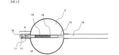
本発明の製造方法により製造された、先端に電極チップを有するカテーテルを示す概略図を図1に示す。Figure 1 shows a schematic diagram of a catheter having an electrode tip at its tip, manufactured by the manufacturing method of the present invention.
図1において、カテーテル1は、カテーテルシャフト2と、カテーテルシャフトの遠位端側に配置されたバルーン3及び電極チップ4を備える。ここで、電極チップ4は、チューブ10と、リング電極11及びリング電極11に接続されたリード線12を備える。In Figure 1, the
電極チップ4は、カテーテルシャフト2の先端側付近に配置され、リング電極に接続されたリード線は、カテーテルシャフトの近位側に向けて延在される。カテーテルシャフト2は、内側シャフト13と外側シャフト14で構成される。内側シャフト13及び外側シャフト14の材質としては、フッ素ポリマー、ポリアミド、ポリウレタン系ポリマー又はポリイミド等が挙げられるが、これに限定されるものではない。内側シャフト13は、バルーン3の内部を通過して、カテーテル1の遠位端まで延在する。The
バルーン3の内部には、高周波通電用電極15と、電極温度センサ16を備える。高周波通電用電極15は、内側シャフト13の外壁部に巻きつけて配置されている。リード線6は、バルーン3の内部において、高周波通電用電極15と内側シャフト13の間に進入し、カテーテル1の後端側に向けて配線される。The
リング電極11を心電位のマッピングに使用する場合等には、電極チップ4がリング電極11を複数備えることで、正確な電位波形を測定することが可能となる。When the
カテーテルシャフト2の近位側には、ハンドル20、コネクタ21、外部電気生理検査機器22、コネクタ23及び高周波発生装置24を備え、リード線12の端部はコネクタ21を介して外部電気生理検査機器22と接続することが可能である。また、リング電極11をRF電極として使用する場合、高周波発生装置と接続することも可能である。The proximal side of the
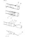
本発明の製造方法における電極チップ4の概略図を図2に示す。A schematic diagram of the
(電極チップ)
電極チップ4は、チューブ10、リング電極11及びリング電極11に接続されたリード線12を備える。チューブ10の内壁には、カテーテルシャフトの内側シャフトが接着されている。電極チップの外壁にはリング電極が配置されている。(Electrode tip)
The
心房内へのアクセスを良好にするため、チューブ10の外径は1mm~6mmが好ましい。チューブ10の材質は熱可塑性樹脂を用いるが、心房内での操作時の安全性を考慮した硬度の観点から、ポリウレタン等がより好ましい。To facilitate good access to the atrium, the outer diameter of the tube 10 is preferably 1 to 6 mm. The material of the tube 10 is a thermoplastic resin, but polyurethane or the like is more preferable from the viewpoint of hardness, which takes into account safety during operation inside the atrium.
(リング電極)
リング電極11の内壁には、リード線12の端部が接合され、リード線12はチューブ10に埋没して延在し、リード線12はリング電極11の近位端から飛び出して、カテーテルシャフト2のルーメン内に向けて配線される。(Ring electrode)
The end of a
電極チップ4は、リング電極11を2つ以上有していてもよい。電極チップ4上に配置されるリング電極11の数には特に制限はなく、各リング電極11及び各リング電極11にそれぞれ接続されたリード線12が相互に電気的に接触することなく配置されていればよい。The
電極チップ4上にリング電極11が複数配置される場合、リング電極11の相互の配置間隔が0.5mm~3.0mmで配置されていることが好ましい。When
製造時の接触を防ぐため、各リング電極11にそれぞれ接続されたリード線12は、チューブ10の形成時にそれぞれのリード線12が最も離れた位置に配置されることが好ましい。例えば、電極チップ4がリング電極11を2つ有する場合、それぞれに接合されたリード線12は、チューブ10の中心を軸として180°対向する位置でリング電極11と接合し、チューブ10内部に埋没している。In order to prevent contact during manufacturing, it is preferable that the
断線のリスクを低減するため、リード線12とリング電極11の接合は、溶接及び半田付け等の方法で固定されることが好ましく、溶接の場合、抵抗溶接及びレーザー溶接が好ましい。To reduce the risk of breakage, it is preferable that the
この電極チップ4は、心房細動等の不整脈等の治療を行うために用いることが出来るため、カテーテルの先端に取付けることができる。用いられるカテーテルとしては、バルーンカテーテル、アブレーションカテーテル及びバルーン付きアブレーションカテーテル等が挙げられるが、バルーン付きアブレーションカテーテルに用いられることが好ましい。This
(リード線)
リード線12の直径は特に規定されないが、配線時の断線のリスクを低減し、電極チップ又はカテーテルシャフト部に配線するスペースを確保しやすくなることから、リード線12の直径は、0.05mm~0.30mmであることが好ましい。(Lead)
The diameter of the
リード線の材質は、リン青銅又は銅等が好ましく用いられる。また、リング電極の材質は、生体への接触を考慮して、白金、白金、ステンレス、金、銀、銅又はそれらの合金等が好ましく用いられる。The preferred materials for the lead wires are phosphor bronze or copper. The preferred materials for the ring electrodes are platinum, stainless steel, gold, silver, copper, or alloys thereof, taking into account contact with the living body.
図3は、本発明の電極チップを有するカテーテルにおける電極チップの製造方法の一連のプロセスを示す概略図である。Figure 3 is a schematic diagram showing a series of processes for manufacturing an electrode tip in a catheter having an electrode tip of the present invention.
(熱可塑性の外層チューブの長手方向に延在するよう、リード線を外層チューブの内腔に配置する配置ステップ)
熱可塑性樹脂を含む外層チューブ30及びリード線12を用意する。熱可塑性の外層チューブ30の長手方向に平行に延在するように、リード線12を外層チューブ30の内腔に配置する。この時、外層チューブ30の内腔で、長手方向に平行に延在するリード線12は、外層チューブ30の長手方向に対して厳密な平行でなくてもよい。 (A placement step of placing the lead wire in the lumen of the thermoplastic outer tube so as to extend in the longitudinal direction of the outer tube)
An
具体的には、リード線12を巻き付けたりすることなく、外層チューブ30の遠位端から近位端に向けて延在させることであって、リード線12のわずかな緩みやたるみによって、厳密な平行とならない場合も含まれる。Specifically, the
(外層チューブが有する開口部からリード線の一端を露出する露出ステップ)
次に、外層チューブ30の外壁に、開口部32を形成して、絶縁被覆を除去したリード線12を露出させる。開口部32の大きさは任意であるが、リング電極11で覆うことが可能な大きさとする。 (Exposing one end of the lead wire from the opening of the outer tube)
Next, an
電極チップ4上にリング電極11が複数配置される場合、対応するリード線12は複数配置されるため、それぞれのリード線12に対応する数の開口部32を外層チューブ30に形成する。また、それぞれの開口部32は、対応するリング電極11の位置にリード線12を露出させるため、外層チューブ30の長手方向に離間した位置に形成される。When
(開口部から露出したリード線の一端とリング電極の内壁とを電気的に接合する接合ステップ)
次に、リード線12の一端とリング電極の内壁とを、溶接又は半田付け等の方法で電気的に接合する。リード線12の一端がリング電極11の内壁と接触するようにして電気的接合を行う。
電気的接合とは、リード線とリング電極間に通電可能なように接合することである。(A joining step for electrically joining one end of the lead wire exposed from the opening to the inner wall of the ring electrode)
Next, one end of the
The electrical connection means connection between the lead wire and the ring electrode so that electricity can be passed between them.
図3に、接合ステップの一例を示す。Figure 3 shows an example of a joining step.
外層チューブ30の内腔において、リード線12を外層チューブ30の長手方向に平行に延在させ、リング電極11を外層チューブ30に被冠させる。次に、外層チューブ30の内腔に電気抵抗溶接用電極の一極42を挿入して、リード線12と電気抵抗溶接用電極42を接触し、開口部32からリード線12を外層チューブ30の外に露出させる。露出したリード線12の一端をリング電極11の内壁に接触させる。In the inner cavity of the
リング電極11の外壁に抵抗溶接用電極の他極43を接触させ、電極間を加圧し、溶接によりリング電極11とリード線12を電気的に接合する。The
抵抗溶接用電極の材質は特に規定しないが、銅、クロム銅及びタングステン等が用いられる。抵抗溶接用電極の一極42の先端形状は、開口部32よりも小さく、リード線12を外層チューブ30の外に露出させ、リング電極11の内壁に接触させることが可能となるよう、チューブの内径形状に合わせた形状であることが好ましく、例えば、外層チューブ30が円筒状であるのであれば、円弧状であることが好ましい。The material of the resistance welding electrode is not particularly specified, but copper, chromium copper, tungsten, etc. are used. The tip shape of one
この方法により、リング電極11の内壁に、リード線12を確実、かつ、短時間で電気的に接合することが可能となる。また、リング電極11により外層チューブ30の開口部32を覆う状態からずれたりせず、リング電極11とリード線12を電気的に接合することが可能となる。このことは、リード線12を開口部32から大きく引き出して、リング電極11の内壁と電気的に接合した上で、リング電極11を外層チューブ30に被冠しながら、余分なリード線12を開口部から引き戻す、という従来の方法に比べ、リード線12の不要な引き出し、引き戻しを行わない点で、断線リスクが低減できるため好ましい。This method makes it possible to reliably and quickly electrically connect the
(リング電極により外層チューブの開口部を覆う被覆ステップ)
外層チューブ30の開口部32を覆うようにリング電極11を被せる。リング電極は前述したリード線との電気的接合を行う前に開口部を覆い、その位置において電気的接合を行ってもよいし、開口部とずらした位置において電気的接合を行い、その後開口部を覆うようにリング電極を被せてもよい。このように、リング電極11を外層チューブ30の開口部32を覆う位置に配置することで、リード線12の外部への露出を防ぐことができる。 (Covering step of covering the opening of the outer tube with a ring electrode)
The
(外層チューブの内腔に内層チューブを挿入する挿入ステップ)
熱可塑性樹脂を含む内層チューブ31を準備し、外層チューブ30の内腔に内層チューブ31を挿入する。このとき、リード線12がチューブの長手方向に延在する配置が維持されたまま外層チューブ30と内層チューブ31の層間に入るよう、内層チューブ31を挿入する。ここで、外層チューブ30の内径は内層チューブ31の外径よりも大きいため、外層チューブ30の内腔に内層チューブ31を挿入することが可能である。なお、内層チューブ31を外層チューブ30の内腔に挿入するステップの後に、外層チューブ30の長手方向に延在するようにリード線12を外層チューブ30の内腔に配置するステップを行なってもよい。この場合、リード線12を外層チューブ30の内腔に配置する際、外層チューブ30と内層チューブ31の層間にリード線12が入るようにする。(Inserting step of inserting the inner layer tube into the inner lumen of the outer layer tube)
An
リード線12が外層チューブ30と内層チューブ31の層間で長手方向に平行に延在するように配置されることで、リード線12がリング電極11から離れる方向に負荷が掛かることを抑制し、リード線12及びリード線12とリング電極11の電気的に接合する部分の断線のリスクを低減できる。またリード線12が2本以上である場合には、リード線の相互の交差や接触のリスクを低減できる。By arranging the
(外層チューブ及び内層チューブを加熱し、外層チューブと内層チューブの層間にリード線が埋没して固定されるように外層チューブと内層チューブとを一体化する一体化ステップ)
外層チューブ30及び内層チューブ31を加熱するための芯線33を内層チューブ31の内腔に挿入する。 (An integration step in which the outer tube and the inner tube are heated to integrate the outer tube and the inner tube so that the lead wire is embedded and fixed between the outer tube and the inner tube)
A
外層チューブ30及び内層チューブ31は熱可塑性樹脂を含むことから、芯線33により加熱することで、外層チューブ30と内層チューブ31が一体化され、チューブ10を形成する。その際、リード線12は外層チューブ30と内層チューブ31の間に配置されているため、外層チューブ30と内層チューブ31の層間にリード線12が長手方向に平行に延在した状態で埋没して固定される。その結果、リード線12がチューブ10内部に平行に延在するように、埋没して固定されるとともに、リング電極11がチューブ10の外壁に固定される。Since the
上記の製造方法の場合、外層チューブ30と内層チューブ31の間にリード線12が平行に延在するように配置した状態で、外層チューブ30と内層チューブ31を一体化してチューブ10を形成するため、リード線12がチューブ10内部で平行に延在するよう固定される。In the above manufacturing method, the
これにより、カテーテル1を操作する際に、電極チップ4が湾曲したとしても、リング電極11とリード線12の電気的接合部分に負荷が掛かることを抑制できる。また、リード線12がよれたり、動いたりすることによる破断が生じづらくなるため、リード線の断線リスクを低減することができる。This prevents stress from being applied to the electrical junction between the
また、リング電極11とリード線12の接合部位の近傍では、リード線12の絶縁被覆が除去され、電気的接触が可能な状態となっている。電極チップ4が複数のリング電極11を備える場合、製造時に複数のリード線12が相互に接触する可能性があるが、外層チューブ30と内層チューブ31を一体化する際にそれぞれのリード線12を平行に延在するように配置することで、それぞれのリード線12の接触を防ぐとともに、チューブ10がリード線12間に配置されるため確実に絶縁することができる。In addition, the insulating coating of the
上記の外層チューブ30、内層チューブ31及びチューブ10の肉厚は任意に設定することができる。また、外層チューブ30と内層チューブ31が同一の熱可塑性樹脂からなる場合、一体化して形成されたチューブ10が安定した強度を有することができるため好ましい。The wall thicknesses of the
図4に、外層チューブ30及び内層チューブ31を加熱し、外層チューブ30と内層チューブ31の層間にリード線12が埋没して固定されるように外層チューブ30と内層チューブ31とを一体化するステップの変形例を示す。Figure 4 shows a modified example of the step of heating the
外層チューブ30と内層チューブ31とを一体化するステップにおいて、内層チューブ31の先端側と後端側の間に圧縮荷重を付与する。外層チューブ30及び内層チューブ31の一端を固定ジグ37で固定し、もう一端に圧縮ばね34を当接し、固定ジグ37で圧縮ばね34を圧縮させた位置で固定する。圧縮荷重を加えながら加熱することが容易になる。In the step of integrating the
次に、熱収縮チューブ35をリング電極11と外層チューブ30の外壁に被冠させる。熱収縮チューブ35は、最小収縮内径が、リング電極11の外径よりも小さいと、十分な収縮力を与えることが可能で好ましい。Next, the heat shrink tube 35 is placed over the
また、内層チューブ31の内腔には、芯線33を挿入する。芯線33は、ステンレス等の金属製であって、加熱により内層チューブ31の密着が生じるため、剥離性のよい表面処理等を施すことが好ましい。A
次に、加熱を行う。加熱源としては、レーザー光36が好ましい。レーザー光36は、炭酸ガスレーザー又は半導体レーザーが好ましい。芯線33を回転させながらレーザー光36を照射することで、一体化の際に、外層チューブ30と内層チューブ31の全周にわたり均一に加熱することが可能となる。また、同時にレーザー光36の照射位置を移動させることで、外層チューブ30と内層チューブ31の長手方向に連続的に加熱することが可能となる。Next, heating is performed. Laser light 36 is preferably used as the heating source. The laser light 36 is preferably a carbon dioxide laser or a semiconductor laser. By irradiating the laser light 36 while rotating the
外層チューブ30及び内層チューブ31に対し長手方向に連続的に加熱を行なうことで、外層チューブ30と内層チューブ31の一体化の際に、リード線12が長手方向に対し延在する配置からずれることを防止することができる。また、リング電極11のみの局所的な加熱に限らず、リング電極11により被覆されていない部分の外層チューブ30及び内層チューブ31の層間も加熱することで、リード線12に不要な負荷が生じるリスクを低減し、各リード線12間の短絡リスクも低減することができる。By continuously heating the
圧縮ばね34により圧縮荷重を加えることで、外層チューブ30及び内層チューブ31が径方向に拡大され、熱収縮チューブ35を被冠して加熱することで、リング電極11と外層チューブ30間の隙間が効果的に埋められ、リング電極11と外層チューブ30の外壁の段差が解消される。熱収縮チューブ35の材質は特に規定しないが、オレフィン樹脂系や、フッ素樹脂系が好ましく用いられる。熱収縮チューブ35は、一体化の加工後に取り外す。By applying a compressive load from the compression spring 34, the
図5は、接合ステップの一例を示す。Figure 5 shows an example of a joining step.
外層チューブの内腔において、リード線をード線を外層チューブ長手方向に略平行に延在させ、リング電極を外層チューブに被冠させる。次に、外層チューブの内腔に電気抵抗溶接用電極の一極42を挿入して、リード線に接触せしめ、開口部においてリード線を外層チューブの外周面より突出させ、リング状電極内周面にリード線を接触させる。In the inner cavity of the outer tube, the lead wire is extended approximately parallel to the longitudinal direction of the outer tube, and the ring electrode is placed on the outer tube. Next, one
リング状電極の外周において、電気抵抗溶接用電極の他極43を接触させ、電極間を加圧して電気抵抗溶接して、電気的に接合する。The
抵抗溶接用電極の材質は特に規定しないが、銅やクロム銅、タングステンなどが用いられる。抵抗溶接用電極の先端形状は、開口部よりも小さく、リード線を開口部から突出させて、リング電極内周面に接触させることが可能となるよう、円弧状の表面であると好ましい。The material of the resistance welding electrode is not particularly specified, but copper, chromium copper, tungsten, etc. are used. The tip shape of the resistance welding electrode is preferably smaller than the opening and has an arc-shaped surface so that the lead wire can protrude from the opening and contact the inner surface of the ring electrode.
図6は、管状部材を用いた配置ステップ及び位置決めステップの一例を示す。Figure 6 shows an example of placement and positioning steps using a tubular member.
(開口部を有する管状部材を外層チューブの内側に配置し、かつ、リード線を外層チューブと管状部材との間に挟持する配置ステップ)
各配置ステップの長時間化を防ぐために、開口部51を有する管状部材50を用意し、前述した外層チューブ30の内腔の長手方向に平行に延在するように配置されたリード線12の内側に、管状部材50をさらに配置する。このように、開口部51を有する管状部材50を外層チューブ30の内側に配置し、かつ、リード線12を外層チューブ30と管状部材50との間に挟持することで、リード線12と外層チューブ30が管状部材50に支持される。ここで、支持とは、外力のない状態において、外層チューブ30とリード線12が、それぞれ配置された位置にて、その状態が維持されていることを意味する。さらに、配置ステップ(1)~(3)において、外層チューブ30及びリード線12に対し外力がかかった際でも、外層チューブ30の内側に管状部材50があることで外層チューブ30の形状が維持されるとともに、リード線12の位置がずれるのを防ぐことができる。(A step of placing a tubular member having an opening inside the outer tube and sandwiching the lead wire between the outer tube and the tubular member)
In order to prevent each arrangement step from taking too long, a tubular member 50 having an opening 51 is prepared, and the tubular member 50 is further arranged inside the
(外層チューブの開口部と管状部材の開口部とが重なるように位置決めする位置決めステップ)
次に、外層チューブ30の開口部32と、管状部材50の開口部51とが重なるように位置決めを行う。これによって、開口部から露出したリード線の一端とリング電極の内壁とを電気的に接合する接合ステップにおいて、管状部材50及び外層チューブ30の内腔に電気抵抗溶接用電極の一極42を挿入して、リード線12と電気抵抗溶接用電極42を接触させる際に、外層チューブ30の開口部と管状部材50の開口部51とが重なってできた開口部からリード線12を外層チューブ30の外に露出させることができ、電気抵抗溶接用電極の一極42の先端は開口部51を通過することで管状部材50に接触することなく、リード線12に接触させることができる。その後、開口部32においてリード線12を外層チューブ30の外周面より突出させ、リング状電極の内周面にリード線を接触させることが可能になる。(Positioning step of positioning the opening of the outer tube so that the opening of the tubular member overlaps with the opening of the outer tube)
Next, the
すなわち、本発明のカテーテルの製造方法の一態様として、開口部を有する管状部材を外層チューブの内側に配置し、かつ、上記リード線を上記外層チューブと上記管状部材との間に挟持する配置ステップ(3)と、上記外層チューブの開口部と上記管状部材の開口部とが重なるように位置決めする位置決めステップと、を備えるカテーテルの製造方法が例示される。この配置ステップ(3)及び位置決めステップは、熱可塑性の外層チューブの長手方向に延在するように、リード線を外層チューブの内腔に配置する配置ステップの後から外層チューブの開口部からリード線の一端を露出する露出ステップの間に行えばよい。That is, one embodiment of the method for manufacturing a catheter of the present invention includes an arrangement step (3) in which a tubular member having an opening is arranged inside an outer tube and the lead wire is sandwiched between the outer tube and the tubular member, and a positioning step in which the opening of the outer tube and the opening of the tubular member are positioned so as to overlap. The arrangement step (3) and the positioning step may be performed after the arrangement step in which the lead wire is arranged in the lumen of the outer tube so as to extend in the longitudinal direction of the thermoplastic outer tube, and during the exposure step in which one end of the lead wire is exposed from the opening of the outer tube.
管状部材50の開口部51の形状は特に規定されないが、外層チューブ30の内側に管状部材50を配置した際に、外層チューブ30が有する開口部と管状部材50の開口部51が重なりやすくなるように形成されていればよく、外層チューブ30の開口部32と同じ形状であることが好ましい。The shape of the opening 51 of the tubular member 50 is not particularly specified, but it need only be formed so that the opening of the
管状部材50の外径は、リード線12を外層チューブ30と管状部材50の間に挟持し、さらにそれらを支持することが可能な範囲であればよく、上記外層チューブの内径をD1、リード線12の直径をD2として、D1-(D2×2)=rとしたとき、管状部材50の外径Rは、0.9×r≦R≦1.1×rの範囲であることが好ましい。The outer diameter of the tubular member 50 may be within a range that allows the
また、管状部材50の内径は特に規定されないが、接合ステップにおいて管状部材50の内腔に電気抵抗溶接用電極の一極42を挿入する際に、電気抵抗溶接用電極の一極42が管状部材50に接触することがなければよい。In addition, the inner diameter of the tubular member 50 is not particularly specified, but it is sufficient that when one
管状部材50の材質は特に規定されないが、製作のし易さ、取扱いのし易さの観点から、金属又は樹脂が好ましい。また、接合ステップにおいて、電気抵抗溶接時に管状部材50に電気が流れ、溶接不良が発生する可能性を防ぐためには、絶縁材料であることがより好ましい。さらに、非絶縁材料の場合であっても電気的に独立していればよい。The material of the tubular member 50 is not particularly specified, but metal or resin is preferable from the viewpoint of ease of manufacture and ease of handling. In addition, in the joining step, in order to prevent the possibility of electricity flowing through the tubular member 50 during electric resistance welding, which may cause welding defects, an insulating material is more preferable. Furthermore, even in the case of a non-insulating material, it is sufficient that it is electrically independent.
この方法を用いることで、リング電極の内周面に、リード線を確実かつ短時間で電気的に接合することが可能であって、リング電極を、外層チューブに被冠したままの状態で、リード線と電気的に接合することが可能となる。このことは、リード線を開口部から大きく引き出して、リング電極の内周面と電気的に接合した上で、リング電極を外層チューブに被冠しながら、余分なリード線を開口部から引き戻す、という従来の方法に比べ、リード線の不要な引き出し、引き戻しを行わない点で、断線リスクが低減でき好ましい。また、接着剤による電気的な接合は、リング電極の内周面と開口部でできた空隙を接着剤で効果的に充填することが困難であり、接着剤の漏れや不足の管理の点で、煩雑であるため、前述した方法が好ましい。By using this method, it is possible to electrically connect the lead wire to the inner surface of the ring electrode reliably and in a short time, and it is possible to electrically connect the ring electrode to the lead wire while it is still in the outer tube. This is preferable because it reduces the risk of disconnection by not drawing out or pulling back the lead wire unnecessarily, compared to the conventional method of drawing out the lead wire far from the opening, electrically connecting it to the inner surface of the ring electrode, and then pulling back the excess lead wire from the opening while the ring electrode is being wrapped around the outer tube. In addition, the above-mentioned method is preferable because it is difficult to effectively fill the gap between the inner surface of the ring electrode and the opening with adhesive, and it is complicated to manage the leakage and shortage of adhesive.
[実施例1]
医療用チュービング装置により、外径3.6mm、内径3.4mm、長さ10mmのポリウレタン製の外層チューブを製作した。この外層チューブにチューブの長手方向の長さ0.9mm、幅1.2mmの開口部を2箇所作成した。1つ目の開口部は、外層チューブの端部から長さ3.5mmの位置に形成し、2つ目の開口部は、1つ目の開口部と外層チューブの外壁において180°対向し、外層チューブの端部から長さ6.5mmの位置に形成した。 [Example 1]
A polyurethane outer layer tube with an outer diameter of 3.6 mm, an inner diameter of 3.4 mm, and a length of 10 mm was produced using a medical tubing device. Two openings, each 0.9 mm long in the longitudinal direction and 1.2 mm wide, were created in this outer layer tube. The first opening was formed at a position 3.5 mm long from the end of the outer layer tube, and the second opening was formed at a position 180° opposite the first opening on the outer wall of the outer layer tube and 6.5 mm long from the end of the outer layer tube.
一方、ポリウレタンで絶縁被覆された、直径0.1mmのリン青銅線の一端において絶縁被覆を除去し、外層チューブの内腔に挿入した。Meanwhile, the insulation was removed from one end of a phosphor bronze wire with a diameter of 0.1 mm and insulated with polyurethane, and the wire was inserted into the inner cavity of the outer tube.
外層チューブの開口部において、絶縁被覆を除去したリン青銅線が露出し、リン青銅線を外層チューブの長手方向に平行となるよう延在させた。At the opening of the outer tube, the phosphor bronze wire was exposed with the insulating coating removed, and the phosphor bronze wire was extended so that it was parallel to the longitudinal direction of the outer tube.
次に、外径3.8mm、内径3.6mm、幅1.5mmの白金イリジウム製リング電極を外層チューブに被冠させ、開口部を覆う位置に配置した。Next, a platinum-iridium ring electrode with an outer diameter of 3.8 mm, an inner diameter of 3.6 mm, and a width of 1.5 mm was placed on the outer tube and positioned to cover the opening.
次に外層チューブの内腔に、先端が0.5mm角のクロム銅製電気抵抗溶接用電極を挿入して、リード線に接触させ、リング電極の外壁に、先端がリング電極の円弧形状に沿う半円弧形状で、幅1.5mmのクロム銅製抵抗溶接用電極を接触させ、電極間15Nで加圧して通電し、抵抗溶接によって接合した。Next, a chromium copper electric resistance welding electrode with a 0.5 mm square tip was inserted into the inner cavity of the outer tube and brought into contact with the lead wire, and a chromium copper electric resistance welding electrode with a width of 1.5 mm and a semicircular arc tip that follows the arc shape of the ring electrode was brought into contact with the outer wall of the ring electrode, a pressure of 15 N was applied between the electrodes, electricity was passed through, and the electrodes were joined by resistance welding.
次に、外層チューブの内腔に、外層チューブと同一材質であって、外径3.4mm、内径1.7mm、長さ15mmの内層チューブを挿入し、外層チューブと内層チューブの層間にリン青銅線を進入させ、長手方向に延在させた。このとき2つのリン青銅線はそれぞれ層間において、180°対向した位置に配置した。Next, an inner tube made of the same material as the outer tube, with an outer diameter of 3.4 mm, an inner diameter of 1.7 mm, and a length of 15 mm, was inserted into the inner cavity of the outer tube, and a phosphor bronze wire was inserted between the layers of the outer tube and the inner tube and extended in the longitudinal direction. At this time, the two phosphor bronze wires were positioned at 180° opposite each other between the layers.
このようにして作成した複層のチューブに、収縮前内径4.5mm、収縮後肉厚0.2mm、長さ10mmのフッ素樹脂製熱収縮チューブを被冠した。The multi-layered tube thus created was then covered with a heat-shrinkable tube made of fluororesin having an inner diameter of 4.5 mm before shrinkage, a wall thickness of 0.2 mm after shrinkage, and a length of 10 mm.
さらに、内層チューブの内腔に、ステンレス製芯材を挿入し、内層チューブの一端を固定して、もう一端には、ばね定数1N/mmの圧縮コイルばねを取り付けて、内層チューブの先端側と後端側の間に10Nの圧縮荷重を与えた。Furthermore, a stainless steel core was inserted into the inner cavity of the inner layer tube, one end of the inner layer tube was fixed, and a compression coil spring with a spring constant of 1 N/mm was attached to the other end, applying a compressive load of 10 N between the front and rear ends of the inner layer tube.
圧縮荷重を与えた状態で、波長940nmのレーザー溶着機を用いて、チューブを回転させながらレーザー光をチューブ長手方向に遷移させながら照射した。While applying a compressive load, a laser welding machine with a wavelength of 940 nm was used to irradiate the tube with laser light, which was shifted along the longitudinal direction of the tube while the tube was rotated.
このようにして作成した電極チップの内腔に、ポリアミド製内側シャフトの遠位側を挿入して接着し、リング電極に接続されたリン青銅線をこの内側シャフトの近位側に向けて配線した。The distal end of a polyamide inner shaft was inserted and glued into the inner cavity of the electrode tip thus created, and a phosphor bronze wire connected to the ring electrode was wired toward the proximal side of the inner shaft.
次に、高周波通電用電極として、絶縁被覆を一部剥いだ銅線と、電極温度センサとして使用するコンスタンタン製のセンサ線を準備し、センサ線挟みながら銅線を内側シャフトにコイル状に巻きつけて、長さ13mmのコイル状の高周波通電用電極、及び高周波通電用電極の後端部に配置された電極温度センサを形成した。銅線及びセンサ線は、内側シャフトに沿って遠位側に向けて配線した。Next, a copper wire with the insulating coating partially stripped off was prepared as the high-frequency electrode, and a constantan sensor wire was prepared as the electrode temperature sensor. The copper wire was then wound around the inner shaft in a coil shape while sandwiching the sensor wire between them, forming a coil-shaped high-frequency electrode with a length of 13 mm, and an electrode temperature sensor located at the rear end of the high-frequency electrode. The copper wire and the sensor wire were wired toward the distal side along the inner shaft.
このようにして形成した高周波通電用電極及び電極温度センサを内包するように、ポリウレタン製のバルーンを配置し、バルーンの遠位側端部を電極チップに熱溶着で固定し、バルーンの近位側端部をポリウレタン製外側シャフトに熱溶着で固定した。A polyurethane balloon was positioned so as to enclose the high-frequency current electrode and electrode temperature sensor formed in this manner, and the distal end of the balloon was fixed to the electrode tip by heat welding, and the proximal end of the balloon was fixed to the polyurethane outer shaft by heat welding.
カテーテルシャフトの近位側には、ハンドルを備え、高周波通電用電極の銅線と電極温度センサ線は、ハンドル内を通って、高周波発生装置用コネクタに接続した。A handle was provided on the proximal side of the catheter shaft, and the copper wire of the high-frequency current electrode and the electrode temperature sensor wire were passed through the handle and connected to the connector for the high-frequency generator.
また、リング電極に接続されたリン青銅線も、ハンドル内を通って、電位測定用コネクタに接続し、実施例の電極チップを有するバルーンカテーテルを作製した。The phosphor bronze wire connected to the ring electrode was also passed through the handle and connected to the potential measurement connector to create a balloon catheter having the electrode tip of the embodiment.
[実施例2]
外径3.3mm、内径2.6mm、長さ12mmのステンレス管に長手方向の長さ0.9mm、幅1.2mmの開口部を2箇所形成し、それぞれの開口部が外層チューブ30の有する開口部と重なるように形成された管状部材を、外層チューブの内腔の長手方向に平行に延在するように配置されたリード線の内側に配置した。これら以外の条件は、実施例1と同様の条件で、実施例2の電極チップを有するバルーンカテーテルを作製した。 [Example 2]
A tubular member was formed in a stainless steel tube having an outer diameter of 3.3 mm, an inner diameter of 2.6 mm, and a length of 12 mm, with two openings, each 0.9 mm long and 1.2 mm wide, so that each opening overlapped an opening in the
(比較例)
実施例に記載のリング電極とリン青銅線を用い、リング電極の内壁に絶縁被覆を除去したリン青銅線を接触させ、抵抗溶接によって両者を接合した。実施例に記載の外層チューブ及び内層チューブを使用せず、リード線をチューブに埋没させることを行わなかった以外は同様にして、比較例の電極チップを有するバルーンカテーテルを作製した。(Comparative Example)
The ring electrode and phosphorus bronze wire described in the Examples were used, the phosphorus bronze wire from which the insulating coating had been removed was brought into contact with the inner wall of the ring electrode, and the two were joined by resistance welding. A balloon catheter having an electrode tip of the Comparative Example was produced in the same manner as described in the Examples, except that the outer layer tube and the inner layer tube described in the Examples were not used, and the lead wire was not embedded in the tube.
(2つのリン青銅線の埋没状態及び短絡状態の確認)
実施例の電極チップについて、長手方向に対して直角に輪切り状に切断すると、一体化した複層チューブにリン青銅線が埋没して固定され、2つのリン青銅線が相互に接触することなく延在していることを確認できた。また、抵抗測定器を用いて、両者が短絡していないことを確認した。(Confirmation of buried and shorted state of two phosphor bronze wires)
When the electrode tip of the embodiment was cut into a ring shape perpendicular to the longitudinal direction, it was confirmed that the phosphor bronze wire was embedded and fixed in the integrated multi-layer tube, and that the two phosphor bronze wires extended without touching each other. It was also confirmed using a resistance meter that the two wires were not short-circuited.
(リン青銅線の接続部強度試験)
実施例1の電極チップについて、リン青銅線とポリウレタン製の複層チューブを、引張試験機によって試験速度10mm/minで相互に引張り、破断強度を測定したところ、7.2Nでリン青銅線が溶接部以外の配線箇所から断線した。(Phosphor bronze wire connection strength test)
For the electrode chip of Example 1, the phosphor bronze wire and the polyurethane multilayer tube were pulled against each other using a tensile testing machine at a test speed of 10 mm/min to measure the breaking strength. At a force of 7.2 N, the phosphor bronze wire broke at a wiring point other than the welded portion.
実施例2の電極チップについて、リン青銅線とポリウレタン製の複層チューブを、引張試験機によって試験速度10mm/minで相互に引張り、破断強度を測定したところ、7.5Nでリン青銅線が溶接部以外の配線箇所から断線した。For the electrode tip of Example 2, the phosphor bronze wire and the polyurethane multi-layer tube were pulled against each other using a tensile testing machine at a test speed of 10 mm/min to measure the breaking strength. At 7.5 N, the phosphor bronze wire broke at a wiring point other than the welded part.
一方、比較例の電極チップについて、リング電極とリン青銅線を引張試験機によって試験速度10mm/minで相互に引張り、破断強度を測定したところ、4.0Nでリン青銅線が溶接部分から断線した。On the other hand, for the electrode tip of the comparative example, the ring electrode and the phosphor bronze wire were pulled against each other using a tensile testing machine at a test speed of 10 mm/min, and the breaking strength was measured. At a force of 4.0 N, the phosphor bronze wire broke at the welded part.
上記の結果から、リング電極の内壁に接合されたリン青銅線が電極チップ中のチューブに埋没して延在することで、リン青銅線の固定を強化し、断線リスクを低減したカテーテルが得られることが分かった。From the above results, it was found that by having the phosphor bronze wire joined to the inner wall of the ring electrode embedded and extending into the tube in the electrode tip, the fixation of the phosphor bronze wire is strengthened, resulting in a catheter with a reduced risk of breakage.
本発明は医療分野において、心房細動等の不整脈等の治療を行うための電極チップを先端に有するカテーテルとして用いることができる。The present invention can be used in the medical field as a catheter having an electrode tip at the tip for treating arrhythmias such as atrial fibrillation.
1・・・カテーテル、2・・・カテーテルシャフト、3・・・バルーン、4・・・電極チップ、10・・・チューブ、11・・・リング電極、12・・・リード線、13・・・内側シャフト、14・・・外側シャフト、15・・・高周波通電用電極、16・・・電極温度センサ、20・・・ハンドル、21・・・コネクタ、22・・・外部電気生理検査機器、23・・・コネクタ、24・・・高周波発生装置、30・・・外層チューブ、31・・・内層チューブ、32・・・開口部、33・・・芯線、34・・・圧縮ばね、35・・・熱収縮チューブ、36・・・レーザー光、37・・・固定ジグ、42・・・電気抵抗溶接用電極の一極、43・・・電気抵抗溶接用電極の他極、50・・・管状部材、51、管状部材の開口部1: catheter, 2: catheter shaft, 3: balloon, 4: electrode tip, 10: tube, 11: ring electrode, 12: lead wire, 13: inner shaft, 14: outer shaft, 15: high-frequency current electrode, 16: electrode temperature sensor, 20: handle, 21: connector, 22: external electrophysiological testing equipment, 23: connector, 24: high-frequency generator, 30: outer tube, 31: inner tube, 32: opening, 33: core wire, 34: compression spring, 35: heat shrink tube, 36: laser light, 37: fixing jig, 42: one pole of electrode for electric resistance welding, 43: other pole of electrode for electric resistance welding, 50: tubular member, 51: opening of tubular member
Claims (4)
Translated fromJapanese前記外層チューブの開口部からリード線の一端を露出する露出ステップと、
前記開口部から露出した前記リード線の一端とリング電極の内壁とを接合する接合ステップ(1)と、
前記リング電極により前記外層チューブの開口部を覆う被覆ステップと、
前記外層チューブの内腔に熱可塑性の内層チューブを挿入する挿入ステップと、
前記外層チューブ及び前記内層チューブを加熱し、前記外層チューブと前記内層チューブの層間に前記リード線が埋没して固定されるように前記外層チューブと前記内層チューブとを一体化して電極チップを形成する一体化ステップと、
を備え、
前記一体化ステップは、前記外層チューブに対し熱収縮チューブを被せ、前記外層チューブ及び前記内層チューブの一端を固定ジグで固定し、もう一端に圧縮ばねを当接し、前記内層チューブの先端側と後端側の間で圧縮ばねにより長手方向に圧縮荷重を付与しながら加熱を行なうことで電極チップを形成する、カテーテルの製造方法。 A placement step (1) of placing a lead wire in an inner lumen of a thermoplastic outer tube so as to extend in a longitudinal direction of the outer tube;
an exposing step of exposing one end of a lead wire from an opening of the outer tube;
a joining step (1) of joining one end of the lead wire exposed from the opening to an inner wall of a ring electrode;
covering the opening of the outer tube with the ring electrode;
inserting a thermoplastic inner tube into the lumen of the outer tube;
an integration step of heating the outer tube and the inner tube to integrate the outer tube and the inner tube so that the lead wire is embedded and fixed between the outer tube and the inner tube to form an electrode tip;
Equippedwith
The integration step of this catheter manufacturing method includes covering the outer tube with a heat shrink tube, fixing one end of the outer tube and the inner tube with a fixing jig, abutting a compression spring to the other end, and forming an electrode tip by heating while applying a compressive load in the longitudinal direction between the front and rear ends of the inner tube with the compression spring .
開口部から露出した前記2つ目のリード線の一端と2つ目のリング電極の内壁とを接合する接合ステップ(2)と、
を前記一体化ステップの前に行うことをさらに備える、請求項1記載の製造方法。 a step (2) of disposing a second lead wire in the lumen of the outer tube so that the second lead wire extends in the longitudinal direction of the outer tube and does not contact the first lead wire;
a joining step (2) of joining one end of the second lead wire exposed from the opening to an inner wall of a second ring electrode;
The method of claim 1 , furthercomprising :
A catheter manufactured by the method according to any one of claims 1 to3 .
Applications Claiming Priority (3)
| Application Number | Priority Date | Filing Date | Title |
|---|---|---|---|
| JP2019067552 | 2019-03-29 | ||
| JP2019067552 | 2019-03-29 | ||
| PCT/JP2020/013954WO2020203740A1 (en) | 2019-03-29 | 2020-03-27 | Method for manufacturing catheter and catheter manufactured by said method |
Publications (2)
| Publication Number | Publication Date |
|---|---|
| JPWO2020203740A1 JPWO2020203740A1 (en) | 2020-10-08 |
| JP7501360B2true JP7501360B2 (en) | 2024-06-18 |
Family
ID=72667651
Family Applications (1)
| Application Number | Title | Priority Date | Filing Date |
|---|---|---|---|
| JP2020519462AActiveJP7501360B2 (en) | 2019-03-29 | 2020-03-27 | Method for manufacturing a catheter and a catheter manufactured by the method |
Country Status (7)
| Country | Link |
|---|---|
| US (1) | US11826094B2 (en) |
| EP (1) | EP3950034A4 (en) |
| JP (1) | JP7501360B2 (en) |
| KR (1) | KR102653115B1 (en) |
| CN (1) | CN113613698B (en) |
| TW (1) | TWI836043B (en) |
| WO (1) | WO2020203740A1 (en) |
Families Citing this family (3)
| Publication number | Priority date | Publication date | Assignee | Title |
|---|---|---|---|---|
| CN113181514A (en)* | 2021-03-26 | 2021-07-30 | 杭州未名信科科技有限公司 | Implantable catheter, method of use and method of making the same |
| CN117065118B (en)* | 2023-10-16 | 2024-01-02 | 四川天府南格尔生物医学有限公司 | Multi-cavity tube for bag-type blood separator and manufacturing method thereof |
| TWI886657B (en)* | 2023-11-27 | 2025-06-11 | 塞爾維亞商尼斯Lmb軟體有限公司 | Device and method for connecting tubes made of plastic |
Citations (4)
| Publication number | Priority date | Publication date | Assignee | Title |
|---|---|---|---|---|
| JP2004065529A (en) | 2002-08-06 | 2004-03-04 | Takayuki Sato | Blood pressure controlling apparatus |
| US20080161774A1 (en) | 2006-12-28 | 2008-07-03 | Hastings John M | Catheter with embedded components and method of its manufacture |
| JP2012192005A (en) | 2011-03-15 | 2012-10-11 | Japan Lifeline Co Ltd | Electrode catheter |
| JP2015116309A (en) | 2013-12-18 | 2015-06-25 | 株式会社カネカ | Catheter manufacturing method and catheter |
Family Cites Families (18)
| Publication number | Priority date | Publication date | Assignee | Title |
|---|---|---|---|---|
| US3600548A (en)* | 1970-07-09 | 1971-08-17 | Bock Corp | Resistance welding apparatus |
| US4239953A (en)* | 1978-11-16 | 1980-12-16 | Bock Corporation | Resistance welding apparatus |
| US4761532A (en)* | 1987-09-30 | 1988-08-02 | Bock Corporation | Resistance welding apparatus |
| US5545149A (en)* | 1993-06-25 | 1996-08-13 | Medtronic, Inc. | Method of catheter segment attachment |
| US5555618A (en) | 1993-10-12 | 1996-09-17 | Arrow International Investment Corp. | Method of making electrode-carrying catheter |
| US5417208A (en)* | 1993-10-12 | 1995-05-23 | Arrow International Investment Corp. | Electrode-carrying catheter and method of making same |
| US5524337A (en)* | 1994-09-21 | 1996-06-11 | Ep Technologies, Inc. | Method of securing ring electrodes onto catheter |
| US5788692A (en)* | 1995-06-30 | 1998-08-04 | Fidus Medical Technology Corporation | Mapping ablation catheter |
| WO1998007523A1 (en)* | 1996-08-23 | 1998-02-26 | Pursley Matt D | Apparatus and method for nonextrusion manufacturing of catheters |
| US6464684B1 (en)* | 1998-09-09 | 2002-10-15 | Scimed Life Systems, Inc. | Catheter having regions of differing braid densities and methods of manufacture therefor |
| US8286338B2 (en)* | 2004-08-05 | 2012-10-16 | Cathrx Ltd | Process of manufacturing a medical use electrical lead |
| US7706891B2 (en) | 2007-03-21 | 2010-04-27 | St. Jude Medical, Atrial Fibrillation Division, Inc. | Catheter employing shape memory alloy shaping wire or pull wire and method of its manufacture |
| JP4163745B1 (en) | 2008-05-07 | 2008-10-08 | 日本ライフライン株式会社 | Electrode catheter |
| RU2531439C2 (en) | 2010-06-08 | 2014-10-20 | Торэй Индастриз, Инк. | Catheter for measuring electrical potential |
| AU2011288968B2 (en)* | 2010-08-13 | 2015-04-16 | Cathrx Ltd | A catheter sheath and a method of manufacturing |
| US8560086B2 (en) | 2010-12-02 | 2013-10-15 | St. Jude Medical, Atrial Fibrillation Division, Inc. | Catheter electrode assemblies and methods of construction therefor |
| US9278187B2 (en)* | 2013-03-13 | 2016-03-08 | Biosense Webster (Israel) Ltd. | Method for making a low OHMIC pressure-contact electrical connection between split ring electrode and lead wire |
| CN111065350B (en) | 2017-09-14 | 2023-06-02 | 圣犹达医疗用品心脏病学部门有限公司 | Torsionally steerable sheath |
- 2020
- 2020-03-27KRKR1020217027938Apatent/KR102653115B1/enactiveActive
- 2020-03-27TWTW109110433Apatent/TWI836043B/enactive
- 2020-03-27USUS17/440,864patent/US11826094B2/enactiveActive
- 2020-03-27CNCN202080026456.9Apatent/CN113613698B/enactiveActive
- 2020-03-27WOPCT/JP2020/013954patent/WO2020203740A1/ennot_activeCeased
- 2020-03-27EPEP20783390.6Apatent/EP3950034A4/enactivePending
- 2020-03-27JPJP2020519462Apatent/JP7501360B2/enactiveActive
Patent Citations (4)
| Publication number | Priority date | Publication date | Assignee | Title |
|---|---|---|---|---|
| JP2004065529A (en) | 2002-08-06 | 2004-03-04 | Takayuki Sato | Blood pressure controlling apparatus |
| US20080161774A1 (en) | 2006-12-28 | 2008-07-03 | Hastings John M | Catheter with embedded components and method of its manufacture |
| JP2012192005A (en) | 2011-03-15 | 2012-10-11 | Japan Lifeline Co Ltd | Electrode catheter |
| JP2015116309A (en) | 2013-12-18 | 2015-06-25 | 株式会社カネカ | Catheter manufacturing method and catheter |
Also Published As
| Publication number | Publication date |
|---|---|
| TW202042856A (en) | 2020-12-01 |
| CN113613698B (en) | 2023-06-20 |
| KR20210124334A (en) | 2021-10-14 |
| EP3950034A4 (en) | 2022-12-14 |
| US20220160422A1 (en) | 2022-05-26 |
| KR102653115B1 (en) | 2024-04-01 |
| TWI836043B (en) | 2024-03-21 |
| EP3950034A1 (en) | 2022-02-09 |
| WO2020203740A1 (en) | 2020-10-08 |
| JPWO2020203740A1 (en) | 2020-10-08 |
| US11826094B2 (en) | 2023-11-28 |
| CN113613698A (en) | 2021-11-05 |
Similar Documents
| Publication | Publication Date | Title |
|---|---|---|
| JP7501360B2 (en) | Method for manufacturing a catheter and a catheter manufactured by the method | |
| US20240366301A1 (en) | Surface mounted electrode catheter | |
| JP5777000B2 (en) | Male coupler for guidewire | |
| KR102426181B1 (en) | Endovascular detachment system with flexible distal end and heater activated detachment | |
| CN112702965B (en) | Medical apparatus and instruments | |
| US20100268251A1 (en) | Delivery wire for occlusive device delivery system and method of manufacture | |
| US20050228469A1 (en) | Electrode and conductor interconnect and method therefor | |
| US6061595A (en) | Laser spot weld winding to connector joint | |
| JP2017113567A (en) | Multi-layered catheter shaft construction with embedded single axial sensors, and related methods | |
| US8141246B2 (en) | Methods and devices for joining cables | |
| CN112704558A (en) | Thermal ablation catheter with profiled tip, thermal ablation device and method of operating same | |
| US20170000980A1 (en) | Robust miniature magnetic sensor | |
| JP6313034B2 (en) | Catheter manufacturing method and catheter | |
| JP7727489B2 (en) | Method for manufacturing an electrode catheter | |
| JP6529770B2 (en) | Electrode catheter, manufacturing method of electrode catheter | |
| CN215606225U (en) | Thermal ablation catheter with profiled tip and thermal ablation device | |
| JP7701855B2 (en) | Electrode catheter and method for manufacturing the same | |
| JP7714439B2 (en) | Electrode catheter and method of manufacturing the same | |
| EP4454583A1 (en) | Plasma guide wire | |
| JP2023080451A (en) | catheter with sensor | |
| JP2020110437A (en) | Catheter manufacturing method and catheter | |
| JP3472997B2 (en) | Manufacturing method of electrode part in multi-electrode probe | |
| WO2024218071A1 (en) | Coiled wire electrode | |
| JP2024139433A (en) | Electrode catheter and method for manufacturing the same | |
| JP3472996B2 (en) | Multi-electrode probe |
Legal Events
| Date | Code | Title | Description |
|---|---|---|---|
| A621 | Written request for application examination | Free format text:JAPANESE INTERMEDIATE CODE: A621 Effective date:20230206 | |
| A131 | Notification of reasons for refusal | Free format text:JAPANESE INTERMEDIATE CODE: A131 Effective date:20231226 | |
| A521 | Request for written amendment filed | Free format text:JAPANESE INTERMEDIATE CODE: A523 Effective date:20240209 | |
| TRDD | Decision of grant or rejection written | ||
| A01 | Written decision to grant a patent or to grant a registration (utility model) | Free format text:JAPANESE INTERMEDIATE CODE: A01 Effective date:20240507 | |
| A61 | First payment of annual fees (during grant procedure) | Free format text:JAPANESE INTERMEDIATE CODE: A61 Effective date:20240520 | |
| R150 | Certificate of patent or registration of utility model | Ref document number:7501360 Country of ref document:JP Free format text:JAPANESE INTERMEDIATE CODE: R150 |