JP7501039B2 - Driving assistance device and computer program - Google Patents
Driving assistance device and computer programDownload PDFInfo
- Publication number
- JP7501039B2 JP7501039B2JP2020058496AJP2020058496AJP7501039B2JP 7501039 B2JP7501039 B2JP 7501039B2JP 2020058496 AJP2020058496 AJP 2020058496AJP 2020058496 AJP2020058496 AJP 2020058496AJP 7501039 B2JP7501039 B2JP 7501039B2
- Authority
- JP
- Japan
- Prior art keywords
- speed
- vehicle
- lane width
- road
- driving
- Prior art date
- Legal status (The legal status is an assumption and is not a legal conclusion. Google has not performed a legal analysis and makes no representation as to the accuracy of the status listed.)
- Active
Links
Images


Landscapes
- Navigation (AREA)
- Control Of Driving Devices And Active Controlling Of Vehicle (AREA)
- Traffic Control Systems (AREA)
Description
Translated fromJapanese本発明は、車両の運転支援を行う運転支援装置及びコンピュータプログラムに関する。The present invention relates to a driving assistance device and a computer program that provide driving assistance for a vehicle.
近年、車両の走行形態として、ユーザの運転操作に基づいて走行する手動走行以外に、ユーザの運転操作の一部又は全てを車両側で実行することにより、ユーザによる車両の運転を補助する自動運転支援システムについて新たに提案されている。自動運転支援システムでは、例えば、車両の現在位置、車両が走行する車線、周辺の他車両の位置を随時検出し、予め設定された経路に沿って走行するようにステアリング、駆動源、ブレーキ等の車両制御が自動で行われる。In recent years, in addition to manual driving, in which the vehicle is driven based on the user's driving operations, new autonomous driving assistance systems have been proposed that assist the user in driving the vehicle by having the vehicle perform some or all of the user's driving operations. In autonomous driving assistance systems, for example, the current position of the vehicle, the lane the vehicle is traveling in, and the positions of other vehicles in the vicinity are detected at any time, and vehicle control such as steering, drive source, and braking is automatically performed so that the vehicle travels along a preset route.
また、上記自動運転支援による走行では、車両の走行速度が予め設定された目標速度で走行するように制御することも行われる。ここで、目標速度を設定する際には、道路に設定された制限速度以外に、車両の走行に影響すると考えられる他の要因についても考慮するのが望ましい。例えば特開2019-26208号公報には、車両に設置されたカメラユニットによって車両の進行方向前方の環境を撮像し、撮像した画像に基づいて車両が走行する道路沿いに設けられた立体物や車線を検出し、立体物からのプレッシャを運転者に与えないようにする為、立体物や車線と通過する車両との間隔に応じて車両が走行する目標速度を設定する技術について提案されている。In addition, in the above-mentioned driving with the autonomous driving assistance, the driving speed of the vehicle is also controlled so that it travels at a preset target speed. Here, when setting the target speed, it is desirable to consider other factors that are thought to affect the driving of the vehicle, in addition to the speed limit set for the road. For example, JP 2019-26208 A proposes a technology in which a camera unit installed in the vehicle captures an image of the environment ahead of the vehicle in the direction of travel, detects three-dimensional objects and lanes along the road on which the vehicle travels based on the captured image, and sets a target speed at which the vehicle travels according to the distance between the three-dimensional objects or lanes and the passing vehicle in order to prevent the driver from feeling pressure from the three-dimensional objects.
しかしながら、上記特許文献1の技術ではカメラユニットによって撮像した撮像画像に基づいて立体物や車線を検出しているので、実際の立体物や車線の位置に対して検出誤差が生じる可能性があり、適切な目標速度が算出できない可能性があった。また、カメラで撮像可能な範囲は車両の進行方向前方のごく限られた範囲となるので、長期的な車両の速度計画を生成することができない問題もあった。However, in the technology of
ここで、車両の速度計画を生成する際には、より長期的な速度計画を生成することが重要である。長期的な速度計画では例えば将来的に減速要因が有るので急減速にならないように予め減速しておくといった、車両や乗員に負担のない速度計画の生成が可能となる。When generating a speed plan for a vehicle, it is important to generate a longer-term speed plan. A long-term speed plan makes it possible to generate a speed plan that does not burden the vehicle or its occupants, for example by slowing down in advance to prevent sudden deceleration in response to a deceleration factor in the future.
本発明は前記従来における問題点を解消するためになされたものであり、車両が走行予定道路を走行する際の推奨速度を事前に正確に特定することが可能となり、長期的な車両の速度計画に基づく運転支援を適切に実施することを可能にした運転支援装置及びコンピュータプログラムを提供することを目的とする。The present invention has been made to solve the above-mentioned problems in the conventional technology, and aims to provide a driving assistance device and computer program that makes it possible to accurately identify in advance the recommended speed for a vehicle to travel on a road on which the vehicle is to travel, and that makes it possible to appropriately implement driving assistance based on a long-term vehicle speed plan.
前記目的を達成するため本発明に係る第1の運転支援装置は、車両が走行する走行予定道路の車線幅を取得する車線幅取得手段と、車線幅と車線を走行する際に推奨される走行速度である推奨速度との対応関係を示す車線幅速度関係情報を取得する関係情報取得手段と、前記走行予定道路の車線幅と前記車線幅速度関係情報とに基づいて、車両が前記走行予定道路を走行する際の車両の速度計画を生成する速度計画生成手段と、前記速度計画に基づいて車両の運転支援を行う運転支援手段と、前記走行予定道路の中央線又は中央分離帯に関する情報を取得する中央線情報取得手段と、を有し、前記速度計画生成手段は、前記走行予定道路に中央線及び中央分離帯が無い場合には、道路幅或いは車道外側線の間の距離のいずれか一方の1/2の距離を前記走行予定道路の車線幅としてみなす一方で、みなした車線幅から所定距離だけ減じた車線幅に対応する推奨速度を前記車線幅速度関係情報を用いて特定した上で車両が前記走行予定道路を走行する際の推奨速度とし、特定された前記推奨速度に基づいて前記車両の速度計画を生成する。
また、本発明に係る第2の運転支援装置は、車両が走行する走行予定道路の車線幅を取得する車線幅取得手段と、車線幅と車線を走行する際に推奨される走行速度である推奨速度との対応関係を示す車線幅速度関係情報を取得する関係情報取得手段と、前記走行予定道路の車線幅と前記車線幅速度関係情報とに基づいて、車両が前記走行予定道路を走行する際の車両の速度計画を生成する速度計画生成手段と、前記速度計画に基づいて車両の運転支援を行う運転支援手段と、前記走行予定道路の中央線又は中央分離帯に関する情報を取得する中央線情報取得手段と、を有し、前記速度計画生成手段は、前記走行予定道路に中央線及び中央分離帯が無い場合には、車両の乗員が自車の走行すべき車線として認識する車線の車線幅を前記走行予定道路の道路情報に基づいて推定し、推定した車線幅に対応する推奨速度を前記車線幅速度関係情報を用いて特定した上で車両が前記走行予定道路を走行する際の推奨速度とし、特定された前記推奨速度に基づいて前記車両の速度計画を生成する。
尚、「車線幅」とは基本的に区画線(車道中央線、車線境界線、車道外側線、誘導線等)が配置された道路については区画線を車線の境界として算出されるが、一部又は全ての区画線のない道路については区画線を仮定して算出される。例えば車道外側線はあるが車道中央線のない対面通行可能な道路では車道外側線の間の距離の1/2を車線幅とする。
また、「運転支援」とは、運転者の車両操作の少なくとも一部を運転者に代わって行う又は補助する機能、或いは運転を支援する為の表示案内や音声案内を行うことをいう。 In order to achieve the above-mentioned object, a first driving assistance device according to the present invention includes a lane width acquisition means for acquiring a lane width of a planned driving road on which a vehicle is to travel, a relationship information acquisition means for acquiring lane width-speed relationship information indicating a correspondence relationship betweenthe lane width and a recommended speed, which is a driving speed recommended when traveling on the lane, a speed plan generation means for generating a speed plan for the vehicle when the vehicle travels on the planned driving road based on the lane width of the planned driving road and the lane width-speed relationship information, a driving assistance means for performing driving assistance for the vehicle based on the speed plan, and a center line information acquisition means for acquiring information on a center line or a center reservation strip of the planned driving road, and the speed plan generation means regards a distance of either one ofthe road width or the distance between the outer side lines of the road as the lane width of the planned driving road when there is no center line or center reservation strip on the planned driving road, while using the lane width-speed relationship information to identify a recommended speed corresponding to a lane width obtained by subtracting a predetermined distance from the assumed lane width, and sets this as the recommended speed when the vehicle travels on the planned driving road, and generates a speed plan for the vehicle based on the identified recommended speed.
Further, the second driving assistance device according to the present invention includes a lane width acquisition means for acquiring the lane width of a planned driving road on which the vehicle is to travel, a relationship information acquisition means for acquiringlane width-speed relationship information indicating the correspondence between the lane width and a recommended speed, which is a recommended driving speed when traveling on the lane, a speed plan generation means for generating a speed plan for the vehicle when the vehicle travels on the planned driving road based on the lane width of the planned driving road and the lane width-speed relationship information, a driving assistance means for performing driving assistance for the vehicle based on the speed plan, and a center line information acquisition means for acquiring information on a center line or a center reservation strip of the planned driving road. When the planned driving road does not have a center line or a center reservation strip, the speed plan generation means estimates the lane width of a lane that a vehicle occupant recognizes as a lane in which the vehicle should travel based on road information of the planned driving road, identifies a recommended speed corresponding to the estimated lane width using the lane width-speed relationship information, and sets it as the recommended speed when the vehicle travels on the planned driving road, and generates a speed plan for the vehicle based on the identified recommended speed.
In addition, the "lane width" is basically calculated using the lane boundaries for roads with dividing lines (center line, lane boundary line, outer side line, guiding line, etc.), but for roads without some or all dividing lines, the lane width is calculated assuming the existence of the dividing lines. For example, on roads with outer side lines but no center line, where two-way traffic is possible, the lane width is set to half the distance between the outer side lines.
Further, "driving assistance" refers to a function of performing or assisting at least a portion of the vehicle operation on behalf of the driver, or providing visual guidance or audio guidance to assist driving.
また、本発明に係る第1のコンピュータプログラムは、車両において実施する運転支援に用いる支援情報を生成するプログラムである。具体的には、コンピュータを、車両が走行する走行予定道路の車線幅を取得する車線幅取得手段と、車線幅と車線を走行する際に推奨される走行速度である推奨速度との対応関係を示す車線幅速度関係情報を取得する関係情報取得手段と、前記走行予定道路の車線幅と前記車線幅速度関係情報とに基づいて、車両が前記走行予定道路を走行する際の車両の速度計画を生成する速度計画生成手段と、前記速度計画に基づいて車両の運転支援を行う運転支援手段と、前記走行予定道路の中央線又は中央分離帯に関する情報を取得する中央線情報取得手段と、して機能させる為のコンピュータプログラムであって、前記速度計画生成手段は、前記走行予定道路に中央線及び中央分離帯が無い場合には、道路幅或いは車道外側線の間の距離のいずれか一方の1/2の距離を前記走行予定道路の車線幅としてみなす一方で、みなした車線幅から所定距離だけ減じた車線幅に対応する推奨速度を前記車線幅速度関係情報を用いて特定した上で車両が前記走行予定道路を走行する際の推奨速度とし、特定された前記推奨速度に基づいて前記車両の速度計画を生成する。
また、本発明に係る第2のコンピュータプログラムは、車両において実施する運転支援に用いる支援情報を生成するプログラムである。具体的には、コンピュータを、車両が走行する走行予定道路の車線幅を取得する車線幅取得手段と、車線幅と車線を走行する際に推奨される走行速度である推奨速度との対応関係を示す車線幅速度関係情報を取得する関係情報取得手段と、前記走行予定道路の車線幅と前記車線幅速度関係情報とに基づいて、車両が前記走行予定道路を走行する際の車両の速度計画を生成する速度計画生成手段と、前記速度計画に基づいて車両の運転支援を行う運転支援手段と、前記速度計画生成手段は、前記走行予定道路に中央線及び中央分離帯が無い場合には、車両の乗員が自車の走行すべき車線として認識する車線の車線幅を前記走行予定道路の道路情報に基づいて推定し、推定した車線幅に対応する推奨速度を前記車線幅速度関係情報を用いて特定した上で車両が前記走行予定道路を走行する際の推奨速度とし、特定された前記推奨速度に基づいて前記車両の速度計画を生成する。 A first computer program according to the present invention is a program for generating assistance information used for driving assistance performed in a vehicle. Specifically, the computer program is for causing a computer to function as a lane width acquisition means for acquiring the lane width of a planned travel road on which a vehicle is to travel, a relationship information acquisition means for acquiring lanewidth -speed relationship information indicating the correspondence between the lane width and a recommended speed, which is a recommended travel speed when traveling on the lane, a speed plan generation means for generating a speed plan for the vehicle when the vehicle travels on the planned travel road based on the lane width of the planned travel road and the lane width-speed relationship information, a driving assistance means for providing driving assistance for the vehicle based on the speed plan, and a center line information acquisition means for acquiring information on the center line or center reservation strip of the planned travel road, in which, when the planned travel road does not have a center line or center reservation strip, the speed plan generation means regards either half ofthe road width or the distance between the outer side lines of the road as the lane width of the planned travel road, while using the lane width-speed relationship information to identify a recommended speed corresponding to a lane width obtained by subtracting a predetermined distance from the assumed lane width, and sets this as the recommended speed when the vehicle travels on the planned travel road, and generates a speed plan for the vehicle based on the identified recommended speed.
A second computer program according to the present invention is a program for generating support information used for driving support implemented in a vehicle. Specifically, the computer includes a lane width acquisition means for acquiring a lane width of a planned road on which the vehicle is to travel, a relationship information acquisition means for acquiringlane width -speed relationship information indicating a correspondence relationship between the lane width and a recommended speed, which is a recommended driving speed when traveling on the lane, a speed plan generation means for generating a speed plan for the vehicle when the vehicle travels on the planned road based on the lane width of the planned road and the lane width-speed relationship information, and a driving support means for performing driving support for the vehicle based on the speed plan. When the planned road does not have a center line or a median strip, the speed plan generation means estimates the lane width of a lane that a vehicle occupant recognizes as a lane in which the vehicle should travel based on road information of the planned road, specifies a recommended speed corresponding to the estimated lane width using the lane width-speed relationship information, and sets it as a recommended speed when the vehicle travels on the planned road, and generates a speed plan for the vehicle based on the specified recommended speed.
前記構成を有する本発明に係る第1及び第2の運転支援装置及びコンピュータプログラムによれば、車線幅と車線を走行する際に推奨される走行速度である推奨速度との対応関係を示す車線幅速度関係情報を用いて車両が走行予定道路を走行する際の推奨速度を特定するので、車両が走行予定道路を走行する際の推奨速度を事前に正確に特定することが可能となる。そして、特定された推奨速度に基づいて長期的な車両の速度計画を生成でき、速度計画に基づく運転支援を適切に実施することが可能となる。また、走行予定道路において中央線や中央分離帯が無い場合には、車両の乗員に恐怖を感じさせることのない適切な推奨速度を特定することが可能となる。 According to the first and second driving assistance devices and computer programs of the present invention having the above configurations, the recommended speed for the vehicle to travel on the planned road is specified usinglane width -speed relationship information indicating the correspondence between the lane width and the recommended speed, which is the recommended travel speed when traveling on the lane, so that the recommended speed for the vehicle to travel on the planned road can be accurately specified in advance. Then, a long-term speed plan for the vehicle can be generated based on the specified recommended speed, and driving assistance based on the speed plan can be appropriately performed. Furthermore, when there is no center line or median strip on the planned road, it is possible to specify an appropriate recommended speed that does not frighten the vehicle occupants.
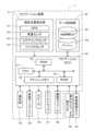
以下、本発明に係る運転支援装置をナビゲーション装置1に具体化した一実施形態について図面を参照しつつ詳細に説明する。先ず、本実施形態に係るナビゲーション装置1を含む運転支援システム2の概略構成について図1及び図2を用いて説明する。図1は本実施形態に係る運転支援システム2を示した概略構成図である。図2は本実施形態に係る運転支援システム2の構成を示したブロック図である。Below, an embodiment in which a driving assistance device according to the present invention is embodied in a
図1に示すように、本実施形態に係る運転支援システム2は、情報配信センタ3が備えるサーバ装置4と、車両5に搭載されて車両5の自動運転に関する各種支援を行うナビゲーション装置1と、を基本的に有する。また、サーバ装置4とナビゲーション装置1は通信ネットワーク網6を介して互いに電子データを送受信可能に構成されている。尚、ナビゲーション装置1の代わりに、車両5に搭載された他の車載器や車両5に関する制御を行う車両制御装置を用いても良い。As shown in FIG. 1, the
ここで、車両5はユーザの運転操作に基づいて走行する手動運転走行に加えて、ユーザの運転操作によらず車両が予め設定された経路や道なりに沿って自動的に走行を行う自動運転支援による支援走行が可能な車両とする。Here,
また、自動運転支援は全ての道路区間に対して行っても良いし、特定の道路区間(例えば境界にゲート(有人無人、有料無料は問わない)が設けられた高速道路)を車両が走行する間のみ行う構成としても良い。以下の説明では車両の自動運転支援が行われる自動運転区間は、一般道や高速道路を含む全ての道路区間に加えて駐車場も含むこととし、車両が走行を開始してから走行を終了するまでの間において基本的に自動運転支援が行われるとして説明する。但し、車両が自動運転区間を走行する場合には必ず自動運転支援が行われるのではなく、ユーザにより自動運転支援を行うことが選択され(例えば自動運転開始ボタンをONする)、且つ自動運転支援による走行を行わせることが可能と判定された状況でのみ行うのが望ましい。一方で、車両5は自動運転支援による支援走行のみ可能な車両としても良い。Autonomous driving assistance may be provided for all road sections, or may be provided only while the vehicle is traveling on a specific road section (for example, a highway with a gate (manned or unmanned, toll or free) at the boundary). In the following explanation, the autonomous driving section where autonomous driving assistance is provided includes all road sections, including general roads and highways, as well as parking lots, and the autonomous driving assistance is basically provided from the time the vehicle starts traveling to the time it ends traveling. However, autonomous driving assistance is not always provided when the vehicle travels on an autonomous driving section, but is preferably provided only when the user selects to provide autonomous driving assistance (for example, by turning on the autonomous driving start button) and it is determined that autonomous driving assistance is possible. On the other hand, the
そして、自動運転支援における車両制御では、例えば、車両の現在位置、車両が走行する車線、周辺の障害物の位置を随時検出し、後述のようにナビゲーション装置1で生成された走行軌道に沿って、同じく生成された速度計画に従った速度で走行するようにステアリング、駆動源、ブレーキ等の車両制御が自動で行われる。尚、本実施形態の自動運転支援による支援走行では、車線変更や右左折についても上記自動運転支援による車両制御を行うことにより走行するが、車線変更や右左折等の特殊な走行については自動運転支援による走行は行わずに手動運転により行う構成としても良い。In the vehicle control for the automated driving assistance, for example, the current position of the vehicle, the lane on which the vehicle is traveling, and the positions of surrounding obstacles are detected at any time, and the vehicle control of the steering, drive source, brakes, etc. is automatically performed so that the vehicle travels along the travel trajectory generated by the
一方、ナビゲーション装置1は、車両5に搭載され、ナビゲーション装置1が有する地図データ或いは外部から取得した地図データに基づいて自車位置周辺の地図を表示したり、地図画像上において車両の現在位置を表示したり、設定された案内経路に沿った移動案内を行う車載機である。本実施形態では特に自動運転支援による支援走行を車両が行う場合に、自動運転支援に関する各種支援情報を生成する。支援情報としては例えば車両の走行が推奨される走行軌道(推奨される車線移動態様を含む)、走行する際の車速を示す速度計画等がある。尚、ナビゲーション装置1の詳細については後述する。Meanwhile, the
また、サーバ装置4は、ナビゲーション装置1の要求に応じて経路探索の実行を行う。具体的には、ナビゲーション装置1において目的地が設定された場合や経路の再探索(リルート)を行う場合に、ナビゲーション装置1からサーバ装置4へと出発地や目的地等の経路探索に必要な情報が経路探索要求とともに送信される(但し、再探索の場合には目的地に関する情報は必ずしも送信する必要は無い)。そして経路探索要求を受信したサーバ装置4は、サーバ装置4の有する地図情報を用いて経路探索を行い、出発地から目的地までの推奨経路を特定する。その後、特定された推奨経路を要求元のナビゲーション装置1へと送信する。そして、ナビゲーション装置1は受信した推奨経路に関する情報をユーザに提供したり、推奨経路を案内経路に設定し、案内経路に従って自動運転支援に関する各種支援情報を生成する。それによって、経路探索時点においてナビゲーション装置1が有する地図情報が古いバージョンの地図情報であったり、ナビゲーション装置1が地図情報自体を有さない場合であっても、サーバ装置4が有する最新バージョンの地図情報に基づいて適切な目的地までの推奨経路を提供することが可能となる。In addition, the
更に、サーバ装置4は、上記経路探索に用いる通常の地図情報とは別に、より精度の高い地図情報である高精度地図情報を有している。高精度地図情報は、例えば道路のレーン形状(車線単位の道路形状や曲率、車線幅、中央帯分離帯の幅等)と道路に描かれた区画線(車道中央線、車線境界線、車道外側線、誘導線等)に関する情報が含まれる。また、その他に交差点に関する情報、駐車場に関する情報等も含まれる。そして、サーバ装置4はナビゲーション装置1からの要求に応じて高精度地図情報を配信し、ナビゲーション装置1はサーバ装置4から配信された高精度地図情報を用いて後述のように自動運転支援に関する各種支援情報を生成する。尚、高精度地図情報は基本的に道路(リンク)及びその周辺のみを対象とした地図情報であるが、道路周辺以外のエリアについても含む地図情報としても良い。Furthermore, the
但し、上述した経路探索処理については必ずしもサーバ装置4で行う必要は無く、地図情報を有するナビゲーション装置1であればナビゲーション装置1で行っても良い。また、高精度地図情報についてもサーバ装置4から配信されるのではなくナビゲーション装置1が予め有するようにしても良い。However, the above-mentioned route search process does not necessarily have to be performed by the
また、通信ネットワーク網6は全国各地に配置された多数の基地局と、各基地局を管理及び制御する通信会社とを含み、基地局及び通信会社を有線(光ファイバー、ISDN等)又は無線で互いに接続することにより構成されている。ここで、基地局はナビゲーション装置1との通信をするトランシーバー(送受信機)とアンテナを有する。そして、基地局は通信会社の間で無線通信を行う一方、通信ネットワーク網6の末端となり、基地局の電波が届く範囲(セル)にあるナビゲーション装置1の通信をサーバ装置4との間で中継する役割を持つ。The
続いて、運転支援システム2におけるサーバ装置4の構成について図2を用いてより詳細に説明する。サーバ装置4は、図2に示すようにサーバ制御部11と、サーバ制御部11に接続された情報記録手段としてのサーバ側地図DB12と、高精度地図DB13と、サーバ側通信装置14とを備える。Next, the configuration of the
サーバ制御部11は、サーバ装置4の全体の制御を行う制御ユニット(MCU、MPU等)であり、演算装置及び制御装置としてのCPU21、並びにCPU21が各種の演算処理を行うにあたってワーキングメモリとして使用されるRAM22、制御用のプログラム等が記録されたROM23、ROM23から読み出したプログラムを記憶するフラッシュメモリ24等の内部記憶装置を備えている。尚、サーバ制御部11は、後述のナビゲーション装置1のECUとともに処理アルゴリズムとしての各種手段を有する。The
一方、サーバ側地図DB12は、外部からの入力データや入力操作に基づいて登録された最新のバージョンの地図情報であるサーバ側地図情報が記憶される記憶手段である。ここで、サーバ側地図情報は、道路網を始めとして経路探索、経路案内及び地図表示に必要な各種情報から構成されている。例えば、道路網を示すノード及びリンクを含むネットワークデータ、道路(リンク)に関するリンクデータ、ノード点に関するノードデータ、各交差点に関する交差点データ、施設等の地点に関する地点データ、地図を表示するための地図表示データ、経路を探索するための探索データ、地点を検索するための検索データ等からなる。Meanwhile, the server-
また、高精度地図DB13は、上記サーバ側地図情報よりも精度の高い地図情報である高精度地図情報15が記憶される記憶手段である。高精度地図情報15は、特に車両が走行対象となる道路や駐車場等に関してより詳細な情報を格納した地図情報であり、本実施形態では例えば道路のレーン形状(車線単位の道路形状や曲率、車線幅、中央分離帯の有無、中央分離帯の幅等)と道路に描かれた区画線(車道中央線、車線境界線、車道外側線、誘導線等)に関する情報が含まれる。また、更に高精度地図DB13としては、道路を構成する各リンクに関してリンクの属する道路の幅員、勾(こう)配、カント、バンク、路面の状態、ノード間のリンク形状(例えばカーブ道路ではカーブの形状)を特定する為の形状補完点データ、合流区間、道路構造、道路の車線数、車線数の減少する箇所、幅員の狭くなる箇所、踏切等を表すデータが、コーナに関して、曲率半径、交差点、T字路、コーナの入口及び出口等を表すデータが、道路属性に関して、降坂路、登坂路等を表すデータが、道路種別に関して、国道、県道、細街路等の一般道のほか、高速自動車国道、都市高速道路、自動車専用道路、一般有料道路、有料橋等の有料道路を表すデータがそれぞれ記録される。特に本実施形態では、道路の車線数に加えて、車線毎の進行方向の通行区分や道路の繋がり(具体的には、交差点の通過前の道路に含まれる車線と交差点の通過後の道路に含まれる車線との対応関係)を特定する情報についても記憶されている。更に、道路に設定されている制限速度についても記憶されている。また、高精度地図情報は基本的に道路(リンク)及びその周辺のみを対象とした地図情報であるが、道路周辺以外のエリアについても含む地図情報としても良い。また、図2に示す例ではサーバ側地図DB12に格納されるサーバ側地図情報と高精度地図情報15とは異なる地図情報としているが、高精度地図情報15はサーバ側地図情報の一部としても良い。The high-
一方、サーバ側通信装置14は各車両5のナビゲーション装置1と通信ネットワーク網6を介して通信を行う為の通信装置である。また、ナビゲーション装置1以外にインターネット網や、交通情報センタ、例えば、VICS(登録商標:Vehicle Information and Communication System)センタ等から送信された渋滞情報、規制情報、交通事故情報等の各情報から成る交通情報の受信についても可能である。On the other hand, the server-
次に、車両5に搭載されたナビゲーション装置1の概略構成について図3を用いて説明する。図3は本実施形態に係るナビゲーション装置1を示したブロック図である。Next, the schematic configuration of the
図3に示すように本実施形態に係るナビゲーション装置1は、ナビゲーション装置1が搭載された車両の現在位置を検出する現在位置検出部31と、各種のデータが記録されたデータ記録部32と、入力された情報に基づいて、各種の演算処理を行うナビゲーションECU33と、ユーザからの操作を受け付ける操作部34と、ユーザに対して車両周辺の地図やナビゲーション装置1で設定されている案内経路(車両の走行予定経路)に関する情報等を表示する液晶ディスプレイ35と、経路案内に関する音声ガイダンスを出力するスピーカ36と、記憶媒体であるDVDを読み取るDVDドライブ37と、プローブセンタやVICSセンタ等の情報センタとの間で通信を行う通信モジュール38と、を有する。また、ナビゲーション装置1はCAN等の車載ネットワークを介して、ナビゲーション装置1の搭載された車両に対して設置された車外カメラ39や各種センサが接続されている。更に、ナビゲーション装置1の搭載された車両に対する各種制御を行う車両制御ECU40とも双方向通信可能に接続されている。As shown in FIG. 3, the
以下に、ナビゲーション装置1が有する各構成要素について順に説明する。
現在位置検出部31は、GPS41、車速センサ42、ステアリングセンサ43、ジャイロセンサ44等からなり、現在の車両の位置、方位、車両の走行速度、現在時刻等を検出することが可能となっている。ここで、特に車速センサ42は、車両の移動距離や車速を検出する為のセンサであり、車両の駆動輪の回転に応じてパルスを発生させ、パルス信号をナビゲーションECU33に出力する。そして、ナビゲーションECU33は発生するパルスを計数することにより駆動輪の回転速度や移動距離を算出する。尚、上記4種類のセンサをナビゲーション装置1が全て備える必要はなく、これらの内の1又は複数種類のセンサのみをナビゲーション装置1が備える構成としても良い。 Each of the components of the
The current
また、データ記録部32は、外部記憶装置及び記録媒体としてのハードディスク(図示せず)と、ハードディスクに記録された地図情報DB45やキャッシュ46や所定のプログラム等を読み出すとともにハードディスクに所定のデータを書き込む為のドライバである記録ヘッド(図示せず)とを備えている。尚、データ記録部32をハードディスクの代わりにフラッシュメモリやメモリーカードやCDやDVD等の光ディスクを有しても良い。また、本実施形態では上述したようにサーバ装置4において目的地までの経路を探索するので、地図情報DB45については省略しても良い。地図情報DB45を省略した場合であっても、必要に応じてサーバ装置4から地図情報を取得することも可能である。The
ここで、地図情報DB45は、例えば、道路(リンク)に関するリンクデータ、ノード点に関するノードデータ、経路の探索や変更に係る処理に用いられる探索データ、施設に関する施設データ、地図を表示するための地図表示データ、各交差点に関する交差点データ、地点を検索するための検索データ等が記憶された記憶手段である。Here, the map information DB45 is a storage means that stores, for example, link data related to roads (links), node data related to node points, search data used in processes related to route search and change, facility data related to facilities, map display data for displaying the map, intersection data related to each intersection, search data for searching for locations, etc.
一方、キャッシュ46は、過去にサーバ装置4から配信された高精度地図情報15が保管される記憶手段である。保管する期間は適宜設定可能であるが、例えば記憶されてから所定期間(例えば1カ月)としても良いし、車両のACC電源(accessory power supply)がOFFされるまでとしても良い。また、キャッシュ46に格納されるデータ量が上限となった後に古いデータから順次削除するようにしても良い。そして、ナビゲーションECU33は、キャッシュ46に格納された高精度地図情報15を用いて、自動運転支援に関する各種支援情報を生成する。詳細については後述する。On the other hand, the
一方、ナビゲーションECU(エレクトロニック・コントロール・ユニット)33は、ナビゲーション装置1の全体の制御を行う電子制御ユニットであり、演算装置及び制御装置としてのCPU51、並びにCPU51が各種の演算処理を行うにあたってワーキングメモリとして使用されるとともに、経路が探索されたときの経路データ等が記憶されるRAM52、制御用のプログラムのほか、後述の自動運転支援プログラム(図4参照)等が記録されたROM53、ROM53から読み出したプログラムを記憶するフラッシュメモリ54等の内部記憶装置を備えている。尚、ナビゲーションECU33は、処理アルゴリズムとしての各種手段を有する。例えば、車線幅取得手段は、車両が走行する走行予定道路の車線幅を取得する。関係情報取得手段は、車線幅の長さと車線を走行する際に推奨される走行速度である推奨速度との対応関係を示す車線幅速度関係情報を取得する。速度計画生成手段は、走行予定道路の車線幅と車線幅速度関係情報とに基づいて、車両が前記走行予定道路を走行する際の車両の速度計画を生成する。運転支援手段は、速度計画に基づいて車両の運転支援を行う。On the other hand, the navigation ECU (electronic control unit) 33 is an electronic control unit that controls the
操作部34は、走行開始地点としての出発地及び走行終了地点としての目的地を入力する際等に操作され、各種のキー、ボタン等の複数の操作スイッチ(図示せず)を有する。そして、ナビゲーションECU33は、各スイッチの押下等により出力されるスイッチ信号に基づき、対応する各種の動作を実行すべく制御を行う。尚、操作部34は液晶ディスプレイ35の前面に設けたタッチパネルを有しても良い。また、マイクと音声認識装置を有しても良い。The
また、液晶ディスプレイ35には、道路を含む地図画像、交通情報、操作案内、操作メニュー、キーの案内、案内経路(走行予定経路)に沿った案内情報、ニュース、天気予報、時刻、メール、テレビ番組等が表示される。尚、液晶ディスプレイ35の代わりに、HUDやHMDを用いても良い。The
また、スピーカ36は、ナビゲーションECU33からの指示に基づいて案内経路(走行予定経路)に沿った走行を案内する音声ガイダンスや、交通情報の案内を出力する。In addition, the
また、DVDドライブ37は、DVDやCD等の記録媒体に記録されたデータを読み取り可能なドライブである。そして、読み取ったデータに基づいて音楽や映像の再生、地図情報DB45の更新等が行われる。尚、DVDドライブ37に替えてメモリーカードを読み書きする為のカードスロットを設けても良い。The
また、通信モジュール38は、交通情報センタ、例えば、VICSセンタやプローブセンタ等から送信された交通情報、プローブ情報、天候情報等を受信する為の通信装置であり、例えば携帯電話機やDCMが該当する。また、車車間で通信を行う車車間通信装置や路側機との間で通信を行う路車間通信装置も含む。また、サーバ装置4で探索された経路情報や高精度地図情報15をサーバ装置4との間で送受信するのにも用いられる。The
また、車外カメラ39は、例えばCCD等の固体撮像素子を用いたカメラにより構成され、車両のフロントバンパの上方に取り付けられるとともに光軸方向を水平より所定角度下方に向けて設置される。そして、車外カメラ39は、車両が自動運転区間を走行する場合において、車両の進行方向前方を撮像する。また、ナビゲーションECU33は撮像された撮像画像に対して画像処理を行うことによって、車両が走行する道路に描かれた区画線や周辺の他車両等の障害物を検出し、検出結果に基づいて自動運転支援に関する各種支援情報を生成する。例えば、障害物を検出した場合には、障害物を回避或いは追従して走行する新たな走行軌道を生成する。尚、車外カメラ39は車両前方以外に後方や側方に配置するように構成しても良い。また、障害物を検出する手段としてはカメラの代わりにミリ波レーダやレーザセンサ等のセンサや車車間通信や路車間通信を用いても良い。The
また、車両制御ECU40は、ナビゲーション装置1が搭載された車両の制御を行う電子制御ユニットである。また、車両制御ECU40にはステアリング、ブレーキ、アクセル等の車両の各駆動部と接続されており、本実施形態では特に車両において自動運転支援が開始された後に、各駆動部を制御することにより車両の自動運転支援を実施する。また、自動運転支援中にユーザによってオーバーライドが行われた場合には、オーバーライドが行われたことを検出する。The
ここで、ナビゲーションECU33は、走行開始後にCANを介して車両制御ECU40に対してナビゲーション装置1で生成された自動運転支援に関する各種支援情報を送信する。そして、車両制御ECU40は受信した各種支援情報を用いて走行開始後の自動運転支援を実施する。支援情報としては例えば車両の走行が推奨される走行軌道、走行する際の車速を示す速度計画等がある。Here, after starting to drive, the
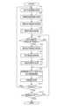
続いて、上記構成を有する本実施形態に係るナビゲーション装置1においてCPU51が実行する自動運転支援プログラムについて図4に基づき説明する。図4は本実施形態に係る自動運転支援プログラムのフローチャートである。ここで、自動運転支援プログラムは、車両のACC電源(accessory power supply)がONされた後であって自動運転支援による車両の走行が開始された場合に実行され、ナビゲーション装置1で生成された支援情報に従って自動運転支援による支援走行を実施するプログラムである。また、以下の図4、図8及び図15にフローチャートで示されるプログラムは、ナビゲーション装置1が備えているRAM52やROM53に記憶されており、CPU51により実行される。Next, the automatic driving assistance program executed by the
先ず、自動運転支援プログラムではステップ(以下、Sと略記する)1において、CPU51は、車両が今後走行する予定にある経路(以下、走行予定経路という)を取得する。尚、車両の走行予定経路は、ナビゲーション装置1において案内経路が設定されている場合には、ナビゲーション装置1において現在設定されている案内経路の内、車両の現在位置から目的地までの経路を走行予定経路とする。一方、ナビゲーション装置1において案内経路が設定されていない場合には、車両の現在位置から道なりに走行する経路を走行予定経路としても良い。First, in step (hereinafter abbreviated as S) 1 of the autonomous driving assistance program, the
また、案内経路はナビゲーション装置1によって設定された出発地から目的地までの推奨経路であり、本実施形態では特にサーバ装置4によって探索される。推奨経路の探索を行う場合には先ずCPU51は、サーバ装置4に対して経路探索要求を送信する。尚、経路探索要求には、経路探索要求の送信元のナビゲーション装置1を特定する端末IDと、出発地(例えば車両の現在位置)及び目的地を特定する情報と、が含まれている。尚、再探索時については目的地を特定する情報は必ずしも必要では無い。その後、CPU51は経路探索要求に応じてサーバ装置4から送信された探索経路情報を受信する。探索経路情報は、送信した経路探索要求に基づいてサーバ装置4が最新のバージョンの地図情報を用いて探索した出発地から目的地までの推奨経路(センタールート)を特定する情報(例えば推奨経路に含まれるリンク列)である。例えば公知のダイクストラ法を用いて探索される。そして、CPU51は、受信した推奨経路をナビゲーション装置1の案内経路として設定する。The guide route is a recommended route from the departure point to the destination set by the
次に、S2においてCPU51は、車両の現在位置から前記S1で取得された走行予定経路に沿った所定距離以内の区間を対象として高精度地図情報15を取得する。例えば車両が現在位置する2次メッシュに含まれる走行予定経路を対象として高精度地図情報15を取得する。但し、高精度地図情報15を取得する対象となるエリアは適宜変更可能であり、例えば車両の現在位置から走行予定経路に沿って3km以内のエリアの高精度地図情報15を取得するようにしても良い。また、走行予定経路の全体を対象として高精度地図情報15を取得しても良い。Next, in S2, the
ここで、高精度地図情報15は図5に示すように矩形形状(例えば500m×1km)に区分されてサーバ装置4の高精度地図DB13に格納されている。従って、例えば図5に示すように走行予定経路61が取得された場合には、車両の現在位置を含む2次メッシュ内にある走行予定経路61を含むエリア62~64を対象として高精度地図情報15が取得される。高精度地図情報15には例えば道路のレーン形状と車線幅と道路に描かれた区画線(車道中央線、車線境界線、車道外側線、誘導線等)に関する情報が含まれる。また、その他に交差点に関する情報、駐車場に関する情報等も含まれる。Here, the high-
また、高精度地図情報15は基本的にサーバ装置4から取得されるが、キャッシュ46に既に格納されているエリアの高精度地図情報15が存在する場合には、キャッシュ46から取得する。また、サーバ装置4から取得された高精度地図情報15はキャッシュ46に一旦格納される。In addition, the high-
その後、S3においてCPU51は、車両の走行予定経路と前記S2で取得した高精度地図情報15とに基づいて、走行予定経路に含まれる道路に対して車両に走行が推奨される走行軌道である静的走行軌道を生成する。静的走行軌道では車両が走行する道路に加えて、道路内において車両が走行する車線についても特定される。更に、静的走行軌道が車線変更を伴う場合には車線変更を行う位置や車線変更の際の推奨される走行軌道についても特定される。また、静的走行軌道が交差点の通過を伴う場合には交差点に進入する車線、交差点から退出する車線、交差点内の推奨される走行軌道についても特定される。Then, in S3, the
ここで、CPU51は上記静的走行軌道を生成する場合には、特に走行予定経路のレーン形状、区画線情報、交差点に関する情報等を用いて静的走行軌道を算出する。尚、レーン形状と区画線情報には、車線数、車線幅、車線数の増減がある場合にはどの位置でどのように増減するか、車線毎の進行方向の通行区分や道路の繋がり(具体的には、交差点の通過前の道路に含まれる車線と交差点の通過後の道路に含まれる車線との対応関係)を特定する情報等を含む。また、交差点に関する情報としては、交差点の形状に加えて交差点上に配置された地物の位置や形状に関する情報を含む。更に、“交差点上に配置された地物”には、誘導線(ガイド白線)、交差点中央に配置されるひし形の導流帯(ダイヤマーク)等の路面に描かれた路面表示の他、ポール等の構造物がある。Here, when generating the static driving trajectory, the
例えば図6は前記S3において生成される静的走行軌道の一例を示した図である。図6に示す静的走行軌道70では、車両の現在位置から現在の車線を直進して進んだ後に交差点71で右折して右側の車線へと進入し、その後に右側の車線が増加するタイミングで更に右側の車線に車線変更し、交差点72でも右折して左側の車線へと進入し、次の交差点73で左折する軌道が算出されている。For example, FIG. 6 is a diagram showing an example of a static driving trajectory generated in S3. In the
尚、静的走行軌道は車両の現在位置から進行方向に沿って所定距離前方までの区間(例えば車両が現在位置する2次メッシュ内、或いは目的地までの全区間)を対象として生成される。所定距離については適宜変更可能であるが、少なくとも車外カメラ39やその他のセンサによって車両周辺の道路状況を検出することが可能な範囲(検出範囲)外を含む領域を対象として静的走行軌道を生成する。前記S3で生成された静的走行軌道は、自動運転支援に用いる支援情報としてフラッシュメモリ54等に格納される。The static driving trajectory is generated for a section from the vehicle's current position along the direction of travel up to a specified distance ahead (for example, within the secondary mesh in which the vehicle is currently located, or the entire section to the destination). The specified distance can be changed as appropriate, but the static driving trajectory is generated for an area that includes at least an area outside the range (detection range) in which the road conditions around the vehicle can be detected by the
次に、S4においてCPU51は、後述の速度計画生成処理(図8)を実行する。ここで、速度計画生成処理は、前記S2で取得した高精度地図情報15に基づいて、前記S3で生成された静的走行軌道を走行する際の車両の速度計画を生成する処理である。Next, in S4, the
続いて、S5においてCPU51は、車外カメラ39で撮像された撮像画像に対して画像処理を行うことによって、周辺の道路状況として、特に自車両の周辺に自車両の走行に影響が生じる要因が存在するか否かを判定する。ここで、前記S5で判定対象となる“自車両の走行に影響が生じる要因”は、リアルタイムで変化する動的な要因とし、道路構造に基づくような静的な要因は除かれる。例えば、自車両の進行方向前方を走行又は駐車する他車両、自車両の進行方向前方に位置する歩行者、自車両の進行方向前方にある工事区間等が該当する。一方で、交差点、カーブ、踏切、合流区間、車線減少区間等は除かれる。また、他車両、歩行者、工事区間が存在する場合であっても、それらが自車両の今後の走行軌道と重複する虞のない場合(例えば自車両の今後の走行軌道から離れた位置にある場合)については“自車両の走行に影響が生じる要因”からは除かれる。また、車両の走行に影響が生じる可能性のある要因を検出する手段としてはカメラの代わりにミリ波レーダやレーザセンサ等のセンサや車車間通信や路車間通信を用いても良い。Next, in S5, the
そして、自車両の周辺に自車両の走行に影響が生じる要因が存在すると判定された場合(S5:YES)には、S6へと移行する。それに対して、自車両の周辺に自車両の走行に影響が生じる要因が存在しないと判定された場合(S5:NO)には、S9へと移行する。If it is determined that there is a factor around the vehicle that may affect the running of the vehicle (S5: YES), the process proceeds to S6. On the other hand, if it is determined that there is no factor around the vehicle that may affect the running of the vehicle (S5: NO), the process proceeds to S9.
S6においてCPU51は、車両の現在位置から前記S5で検出された“自車両の走行に影響が生じる要因”を回避或いは追従して静的走行軌道に戻る為の新たな軌道を動的走行軌道として生成する。尚、動的走行軌道は“自車両の走行に影響が生じる要因”を含む区間を対象として生成される。また、区間の長さは要因の内容によって変化する。例えば、“自車両の走行に影響が生じる要因”が車両の前方を走行する他車両(前方車両)である場合には、図7に示すように右側に車線変更して前方車両75を追い越し、その後に左側に車線変更して元の車線に戻るまでの軌道である回避軌道が動的走行軌道76として生成される。尚、前方車両75を追い越さずに前方車両75の所定距離後方を追従して走行(或いは前方車両75と並走)する軌道である追従軌道を動的走行軌道として生成しても良い。In S6, the
図7に示す動的走行軌道76の算出方法を例に挙げて説明すると、CPU51は先ずステアリングの旋回を開始して右側の車線へと移動し、且つステアリングの位置が直進方向に戻るのに必要な第1の軌道L1を算出する。尚、第1の軌道L1は車両の現在の車速に基づいて車線変更を行う際に生じる横方向の加速度(横G)を算出し、横Gが自動運転支援に支障が生じることなく、また車両の乗員に不快感を与えない上限値(例えば0.2G)を超えないことを条件として、クロソイド曲線を用いてできる限り円滑で、且つできる限り車線変更に必要な距離が短くなる軌道を算出する。また、前方車両75との間に適切な車間距離D以上を維持することについても条件とする。
次に、右側の車線を制限速度を上限に走行して前方車両75を追い越し、且つ前方車両75との間を適切な車間距離D以上とするまでの第2の軌道L2を算出する。尚、第2の軌道L2は基本的に直線の軌道であり、また軌道の長さは、前方車両75の車速と道路の制限速度に基づいて算出される。
続いて、ステアリングの旋回を開始して左側の車線へと戻り、且つステアリングの位置が直進方向に戻るのに必要な第3の軌道L3を算出する。尚、第3の軌道L3は車両の現在の車速に基づいて車線変更を行う際に生じる横方向の加速度(横G)を算出し、横Gが自動運転支援に支障が生じることなく、また車両の乗員に不快感を与えない上限値(例えば0.2G)を超えないことを条件として、クロソイド曲線を用いてできる限り円滑で、且つできる限り車線変更に必要な距離が短くなる軌道を算出する。また、前方車両75との間に適切な車間距離D以上を維持することについても条件とする。
尚、動的走行軌道は、車外カメラ39やその他のセンサで取得した車両周辺の道路状況に基づいて生成されるので、動的走行軌道が生成される対象となる領域は、少なくとも車外カメラ39やその他のセンサによって車両周辺の道路状況を検出することが可能な範囲(検出範囲)内となる。 To explain the calculation method of the
Next, a second trajectory L2 is calculated for traveling in the right lane at the upper limit of the speed limit to overtake the preceding
Next, a third trajectory L3 is calculated, which is required to start turning the steering wheel and return to the left lane, and to return the steering wheel position to the straight-ahead direction. The third trajectory L3 is calculated by calculating the lateral acceleration (lateral G) that occurs when changing lanes based on the current vehicle speed of the vehicle, and using a clothoid curve, a trajectory that is as smooth as possible and requires as short a distance as possible to change lanes, under the condition that the lateral G does not interfere with the automatic driving assistance and does not exceed an upper limit (e.g., 0.2 G) that does not cause discomfort to the vehicle occupants. Another condition is that an appropriate distance D or more must be maintained between the vehicle and the vehicle ahead 75.
Furthermore, since the dynamic driving trajectory is generated based on the road conditions around the vehicle obtained by the
続いて、S7においてCPU51は、前記S6で新たに生成された動的走行軌道を、前記S3で生成された静的走行軌道に反映する。具体的には、車両の現在位置から“自車両の走行に影響が生じる要因”を含む区間の終端まで、静的走行軌道と動的走行軌道の夫々のコストを算出し、該コストが最少となる走行軌道を選択する。結果的に、必要に応じて静的走行軌道の一部が動的走行軌道に置き換わることになる。尚、状況によっては動的走行軌道の置き換えが行われない場合、即ち動的走行軌道の反映が行われても前記S3で生成された静的走行軌道から変化しない場合もある。更に、動的走行軌道と静的走行軌道が同じ軌道である場合には、置き換えが行われても前記S3で生成された静的走行軌道から変化しない場合もある。Next, in S7, the
次に、S8においてCPU51は、後述の速度計画修正処理(図15)を実行する。ここで、速度計画修正処理は、前記S7で動的走行軌道が反映された後の静的走行軌道について、反映された動的走行軌道の内容に基づいて前記S4で生成された車両の速度計画を修正する処理である。尚、動的走行軌道の反映が行われた結果、前記S3で生成された静的走行軌道から変化しない場合には、S8の処理については省略しても良い。Next, in S8, the
続いて、S9においてCPU51は、前記S3で生成された静的走行軌道(前記S7で動的走行軌道の反映が行われている場合には反映後の軌道)を前記S4で生成された速度計画(前記S8で速度計画の修正が行われている場合には修正後の計画)に従った速度で車両が走行する為の制御量を演算する。具体的には、アクセル、ブレーキ、ギヤ及びステアリングの制御量が夫々演算される。尚、S9及びS10の処理についてはナビゲーション装置1ではなく車両を制御する車両制御ECU40が行うようにしても良い。Next, in S9, the
その後、S10においてCPU51は、S9において演算された制御量を反映する。具体的には、演算された制御量を、CANを介して車両制御ECU40へと送信する。車両制御ECU40では受信した制御量に基づいてアクセル、ブレーキ、ギヤ及びステアリングの各車両制御が行われる。その結果、前記S3で生成された静的走行軌道(前記S7で動的走行軌道の反映が行われている場合には反映後の軌道)を前記S4で生成された速度計画(前記S8で速度計画の修正が行われている場合には修正後の計画)に従った速度で走行する走行支援制御が可能となる。Then, in S10, the
次に、S11においてCPU51は、前記S3で静的走行軌道の生成が行われてから車両が一定距離走行したか否かを判定する。例えば一定距離は1kmとする。Next, in S11, the
そして、前記S3で静的走行軌道の生成が行われてから車両が一定距離走行したと判定された場合(S11:YES)には、S1へと戻る。その後、車両の現在位置から走行予定経路に沿った所定距離以内の区間を対象として、静的走行軌道の生成が再度行われる(S1~S4)。尚、本実施形態では車両が一定距離(例えば1km)走行する度に、車両の現在位置から走行予定経路に沿った所定距離以内の区間を対象として、静的走行軌道の生成が繰り返し行われることとしているが、目的地までの距離が短い場合には走行開始時点において目的地までの静的走行軌道の生成を一度に行うようにしても良い。If it is determined that the vehicle has traveled a certain distance since the static driving trajectory was generated in S3 (S11: YES), the process returns to S1. After that, the static driving trajectory is generated again for a section within a certain distance from the vehicle's current position along the planned driving route (S1 to S4). Note that in this embodiment, the static driving trajectory is repeatedly generated for a section within a certain distance from the vehicle's current position along the planned driving route each time the vehicle travels a certain distance (for example, 1 km), but if the distance to the destination is short, the static driving trajectory to the destination may be generated all at once at the start of driving.
一方、前記S3で静的走行軌道の生成が行われてから車両が一定距離走行していないと判定された場合(S11:NO)には、自動運転支援による支援走行を終了するか否かを判定する(S12)。自動運転支援による支援走行を終了する場合としては、目的地に到着した場合以外に、ユーザが車両に設けられた操作パネルを操作したり、ハンドル操作やブレーキ操作などが行われることによって自動運転支援による走行を意図的に解除(オーバーライド)した場合がある。On the other hand, if it is determined that the vehicle has not traveled a certain distance since the static driving trajectory was generated in S3 (S11: NO), it is determined whether or not to end the assisted driving by autonomous driving assistance (S12). Assisted driving by autonomous driving assistance can be ended not only when the vehicle has arrived at the destination, but also when the user intentionally cancels (overrides) the assisted driving by autonomous driving assistance by operating an operation panel provided in the vehicle, or by operating the steering wheel or brakes.
そして、自動運転支援による支援走行を終了すると判定された場合(S12:YES)には、当該自動運転支援プログラムを終了する。それに対して自動運転支援による支援走行を継続すると判定された場合(S12:NO)には、S5へと戻る。If it is determined that the assisted driving by the automated driving assistance should be ended (S12: YES), the automated driving assistance program is ended. On the other hand, if it is determined that the assisted driving by the automated driving assistance should be continued (S12: NO), the process returns to S5.
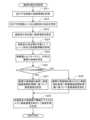
次に、前記S4において実行される速度計画生成処理のサブ処理について図8に基づき説明する。図8は速度計画生成処理のサブ処理プログラムのフローチャートである。Next, the sub-processing of the speed plan generation process executed in S4 will be described with reference to FIG. 8. FIG. 8 is a flowchart of the sub-processing program of the speed plan generation process.
先ず、S21においてCPU51は、地図情報を用いて車両の走行予定経路に含まれる各道路について制限速度情報を取得する。尚、制限速度情報が取得できない道路については道路種別に基づいて制限速度を特定する。例えば細街路は30km/h、幹線道路以外の一般道路は40km/h、国道などの幹線道路は60km/h、高速道路は100km/hとする。尚、制限速度情報は高精度地図情報15から取得しても良いし、経路探索に用いる通常の地図情報から取得しても良い。First, in S21, the
次に、S22においてCPU51は、走行予定経路の内、前記S3で生成された静的走行軌道上において車両の速度を変化させる地点である速度変化地点を特定する。ここで、速度変化地点としては、例えば交差点、カーブ、踏切、横断歩道などが該当する。走行予定経路上に複数の速度変化地点がある場合には、複数の速度変化地点について特定する。Next, in S22, the
続いて、S23においてCPU51は、前記S32で特定された速度変化地点毎に速度変化地点を通過する推奨速度を設定する。例えば、踏切や一時停止線のある交差点では、先ず停止(0km/h)し、その後に徐行速度(例えば10km/h)で通過する態様を推奨速度とする。また、カーブや右左折対象となる交差点では車両に生じる横方向の加速度(横G)が自動運転支援に支障が生じることなく、また車両の乗員に不快感を与えない上限値(例えば0.2G)を超えない速度を推奨速度とする。例えばカーブの曲率や交差点の形状などに基づいて算出される。Next, in S23, the
次に、S24においてCPU51は、前記S32で特定された速度変化地点に該当しない区間(速度変化地点の間の区間であり、以下速度変化地点間という)について、前記S2で取得した高精度地図情報15に基づいて、レーン形状及び区画線情報を取得する。尚、前記S24で取得されるレーン形状には、車線数、車線幅、中央分離帯の有無、中央分離帯の幅等が含まれる。また、区画線情報としては車道中央線、車線境界線、車道外側線、誘導線等に関する情報が含まれる。Next, in S24, the
その後、S25においてCPU51は、先ず前記S24で取得した速度変化地点間のレーン形状に基づいて、速度変化地点間の車線幅を特定する。尚、高精度地図情報15において車線幅が予め特定されている道路については、高精度地図情報15に含まれる車線幅を用いて特定する、一方、高精度地図情報15において車線幅が特定されていない道路については、例えば区画線や道路幅を用いて車線幅を算出する。また、車外カメラ39で撮像した撮像画像に基づいて算出することも可能である。尚、前記S3で生成された静的走行軌道には、車両が走行する道路に加えて車両が走行する車線についても特定されているので、前記S25では特に車両が走行する車線の車線幅について特定しても良い。Then, in S25, the
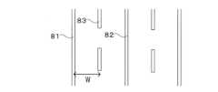
ここで、前記S25で特定される速度変化地点間の車線幅は、例えば図9に示すように区画線として車道外側線81と車道中央線82が設けられた道路では、車道外側線81と車道中央線82との間の距離Wとなる。一方、図10に示すように区画線として車道外側線81と車道中央線82と車線境界線83とが設けられた道路では、車道外側線81と車線境界線83(或いは車道中央線82と車線境界線83、若しくは車線境界線83同士)との間の距離Wとなる。尚、車道中央線82の代わりが中央分離帯となる場合もある。The lane width between the speed change points identified in S25 is the distance W between the
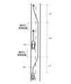
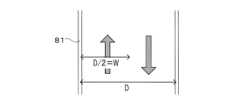
一方、一部又は全ての区画線のない道路については区画線を仮定して速度変化地点間の車線幅が算出される。例えば図11に示すように車道外側線81はあるが車道中央線のない対面通行可能な道路では車道外側線の間の距離Dの1/2を車線幅Wとする。更に、車道外側線81もない道路については道路幅の距離の1/2を車線幅Wとする。On the other hand, for roads that do not have any or all lane markings, the lane width between the speed change points is calculated assuming the presence of lane markings. For example, as shown in FIG. 11, on a road that has an
また、前記S25においてCPU51は、速度変化地点間の車道中央線(センターライン)及び中央分離帯の有無についても取得する。In addition, in S25, the
続いて、S26においてCPU51は、速度変化地点間において車道中央線又は中央分離帯があるか否か判定する。そして、速度変化地点間において車道中央線又は中央分離帯があると判定された場合(S26:YES)には、S27へと移行する。それに対して、速度変化地点間において車道中央線も中央分離帯もないと判定された場合(S26:NO)には、S28へと移行する。但し、一方通行の道路及び二条道路(対向車線と区分された道路)である場合については例外的に車道中央線も中央分離帯もない場合であってもS27へと移行する。Next, in S26, the
尚、以下のS26~S28の処理は前記S2で生成された静的走行軌道の内、速度変化地点間を対象として推奨速度を設定する処理であるが、リンク毎或いはリンクより細かい区画単位(例えば300m毎)で繰り返し行い、前記S3で生成された静的走行軌道の全体に対して推奨速度を設定する。The processes in steps S26 to S28 below are for setting the recommended speed between the speed change points on the static driving track generated in step S2. These processes are repeated for each link or for smaller sections than a link (e.g., every 300 m), and the recommended speed is set for the entire static driving track generated in step S3.
S27においてCPU51は、先ず、車線幅の長さと車線を走行する際に推奨される走行速度である推奨速度との対応関係を示す車線幅速度関係情報を取得する。車線幅速度関係情報は、例えば関数、テーブル等によって車線幅の長さと推奨速度との対応関係を示した情報であり、事前に生成されてフラッシュメモリ54等に格納されている。In S27, the
ここで、図12は車線幅速度関係情報の一例を示した図である。本実施形態では図12に示すように車線幅速度関係情報は、一次関数によって特定されておりy軸を推奨速度[km/h]、x軸を車線幅[m]とした場合に例えば以下の式(1)となる。
y=40x-80・・・・(1) Here, Fig. 12 is a diagram showing an example of the lane width-speed relationship information. In this embodiment, as shown in Fig. 12, the lane width-speed relationship information is specified by a linear function, and is expressed as the following formula (1), for example, when the y-axis is the recommended speed [km/h] and the x-axis is the lane width [m].
y = 40x - 80 ... (1)
以下に、図12に示す車線幅速度関係情報の導出方法の一例について説明する。
例えば車線幅が2m以下の場合は、車両が実質的に通行できないので推奨速度は0km/hとする。道路幅が5.5m(即ち車線幅が2.75m)の道路は、基本的に細街路となるので推奨速度は30km/hとする。また、車線幅が3.5mの道路は、一般的に国道などの幹線道路となるので推奨速度は60km/hとする。各点を座標系にプロットした後にxとyの関係を示す一次近似式を算出することによって上記式(1)が導出される。尚、車線幅速度関係情報の導出方法は上記方法に限られることなく、例えば全国の各車両から収集したプローブ情報に基づいて車線幅の長さと走行する車両の車速の関係を特定し、特定した関係に基づいて車線幅速度関係情報を導出しても良い。 An example of a method for deriving the lane width-speed relationship information shown in FIG. 12 will be described below.
For example, when the lane width is 2m or less, the vehicle cannot pass through the road, and the recommended speed is set to 0km/h. A road with a road width of 5.5m (i.e., lane width of 2.75m) is basically a narrow street, and the recommended speed is set to 30km/h. A road with a lane width of 3.5m is generally a trunk road such as a national highway, and the recommended speed is set to 60km/h. The above formula (1) is derived by plotting each point on a coordinate system and then calculating a linear approximation equation showing the relationship between x and y. Note that the method of deriving the lane width speed relationship information is not limited to the above method. For example, the relationship between the length of the lane width and the vehicle speed of the vehicle traveling on the lane width may be identified based on probe information collected from each vehicle nationwide, and the lane width speed relationship information may be derived based on the identified relationship.
そして、前記S27においてCPU51は、前記S25で特定された車線幅に対応する推奨速度を車線幅速度関係情報に基づいて特定する。但し、特定された推奨速度がその道路の制限速度を超えている場合には制限速度を上限として推奨速度を特定する。そして特定された推奨速度を速度変化地点間の推奨速度として設定する。同様の処理を静的走行軌道に含まれる速度変化地点間の内、車道中央線又は中央分離帯があると判定された全ての区間を対象として行う。Then, in S27, the
一方、S28においてCPU51は、前記S25で特定された車線幅を所定割合減少した車線幅に対応する推奨速度を車線幅速度関係情報に基づいて特定する。但し、特定された推奨速度がその道路の制限速度を超えている場合には制限速度を上限として推奨速度を特定する。そして特定された推奨速度を速度変化地点間の推奨速度として設定する。尚、減少する割合は適宜変更可能であるが例えば3割減少させる。同様の処理を静的走行軌道に含まれる速度変化地点間の内、車道中央線も中央分離帯もないと判定された全ての区間を対象として行う。Meanwhile, in S28, the
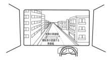
ここで、図13に示すように対面通行可能な道路で車道中央線(センターライン)の無い道路を走行する車両の運転者は、実際の車線幅(車道外側線の間の距離の1/2)よりも長さが短く(狭く)自車の走行すべき車線幅を認識する傾向にある。従って、前記S28では実際の車線幅よりも運転者の認識する車線幅を優先して推奨速度を設定する為に、前記S25で特定された車線幅を所定割合減少させる。その結果、運転者の認識に対応した推奨速度(運転者に恐怖感を与えることのない速度)を設定することが可能となる。As shown in FIG. 13, drivers of vehicles traveling on roads that allow two-way traffic and have no center line tend to perceive the lane width in which their vehicle should travel as shorter (narrower) than the actual lane width (half the distance between the outer lane lines). Therefore, in S28, the lane width identified in S25 is reduced by a predetermined percentage in order to set the recommended speed by prioritizing the lane width perceived by the driver over the actual lane width. As a result, it becomes possible to set a recommended speed that corresponds to the driver's perception (a speed that does not cause the driver a sense of fear).
その後、S29においてCPU51は、前記S23で設定された速度変化地点の推奨速度と、前記S27及びS28で設定された速度変化地点以外の推奨速度を組み合わせ、静的走行軌道に沿って推奨速度の推移を車両の進行方向に示したデータを車両の速度計画として生成する。また、速度計画を生成する際には、速度変化地点間の速度変化が所定条件を満たす、より具体的には静的走行軌道に沿って走行する車両の加速度及び減速度がそれぞれ閾値以下となる条件を満たすように速度計画を適宜修正する。Then, in S29, the
ここで、図14は前記S29で生成される車両の速度計画の一例を示した図である。図14に示すように速度計画では、速度変化地点以外の推奨速度は車線幅に基づいて設定された推奨速度となる。尚、推奨速度の上限はその道路の制限速度である。一方で、カーブや交差点等の速度変化地点については、車線幅に基づく推奨速度よりも低い速度が推奨速度となる。更に、静的走行軌道に沿って走行する車両の加速度及び減速度がそれぞれ閾値以下となる条件を満たすように推奨速度を修正する。但し、推奨速度は基本的に下げる方向にのみ修正し、且つ条件を満たす範囲で推奨速度はできる限り下げないように修正する。また、加速度及び減速度の閾値は、車両の走行や自動運転支援に支障が生じることなく、また車両の乗員に不快感を与えない加速度及び減速度の上限値とする。加速度の閾値と減速度の閾値を異なる値としても良い。その結果、図14に示すように推奨速度が修正され、速度計画が生成される。Here, FIG. 14 is a diagram showing an example of a speed plan for a vehicle generated in S29. As shown in FIG. 14, in the speed plan, the recommended speed other than at the speed change point is the recommended speed set based on the lane width. The upper limit of the recommended speed is the speed limit of the road. On the other hand, for speed change points such as curves and intersections, the recommended speed is lower than the recommended speed based on the lane width. Furthermore, the recommended speed is corrected so as to satisfy the condition that the acceleration and deceleration of the vehicle traveling along the static traveling trajectory are each equal to or lower than the threshold value. However, the recommended speed is basically corrected only in the direction of decreasing, and is corrected so as not to decrease as much as possible within the range that satisfies the condition. In addition, the threshold values of acceleration and deceleration are set to the upper limit values of acceleration and deceleration that do not interfere with the traveling of the vehicle or automatic driving assistance, and do not cause discomfort to the vehicle occupants. The threshold value of acceleration and deceleration may be different values. As a result, the recommended speed is corrected as shown in FIG. 14, and a speed plan is generated.
そして、前記S29で生成された速度計画は、自動運転支援に用いる支援情報としてフラッシュメモリ54等に格納される。また、前記S29で生成された速度計画を実現する為に必要な車両の加減速を示す加速度の計画についても自動運転支援に用いる支援情報として生成するようにしても良いThe speed plan generated in S29 is stored in the
次に、前記S8において実行される速度計画修正処理のサブ処理について図15に基づき説明する。図15は速度計画修正処理のサブ処理プログラムのフローチャートである。Next, the sub-processing of the speed plan correction process executed in S8 will be described with reference to FIG. 15. FIG. 15 is a flowchart of the sub-processing program of the speed plan correction process.
先ず、S31においてCPU51は、前記S7の走行軌道反映処理において静的走行軌道の一部が動的走行軌道の内、特に回避軌道に置き換えられたか否かを判定する。尚、回避軌道は動的走行軌道の一つであり、図7に示すように自車両が影響要因を回避して静的走行軌道に戻る(即ち追い越しする)為の軌道である。First, in S31, the
そして、前記S7の走行軌道反映処理において静的走行軌道の一部が回避軌道に置き換えられたと判定された場合(S31:YES)には、S32へと移行する。それに対して、前記S7の走行軌道反映処理において静的走行軌道の一部が回避軌道に置き換えられていないと判定された場合(S31:NO)には、S33へと移行する。If it is determined in the driving trajectory reflection process of S7 that a part of the static driving trajectory has been replaced with an avoidance trajectory (S31: YES), the process proceeds to S32. On the other hand, if it is determined in the driving trajectory reflection process of S7 that a part of the static driving trajectory has not been replaced with an avoidance trajectory (S31: NO), the process proceeds to S33.
S32においてCPU51は、前記S4で生成された速度計画(図14参照)の内、回避軌道に置き換えられた区間を対象として、回避軌道を走行する際の自車両の推奨速度へと速度計画を修正する。尚、回避軌道を走行する際の自車両の推奨速度は、回避対象となる影響要因(例えば前方車両)の移動速度や道路の制限速度などを考慮して算出される。In S32, the
次に、S33においてCPU51は、前記S7の走行軌道反映処理において静的走行軌道の一部が動的走行軌道の内、特に追従軌道に置き換えられたか否かを判定する。尚、追従軌道は動的走行軌道の一つであり、自車両が車線変更を行うことなく影響要因に対して追従(或いは並走)して走行する為の軌道である。Next, in S33, the
そして、前記S7の走行軌道反映処理において静的走行軌道の一部が追従軌道に置き換えられたと判定された場合(S33:YES)には、S34へと移行する。それに対して、前記S7の走行軌道反映処理において静的走行軌道の一部が追従軌道に置き換えられていないと判定された場合(S33:NO)には速度計画修正処理を終了し、S9へと移行する。尚、追従軌道を走行する際の自車両の推奨速度は、追従対象となる影響要因(例えば前方車両)の移動速度や道路の制限速度などを考慮して算出される。If it is determined in the driving trajectory reflection process of S7 that a part of the static driving trajectory has been replaced with the following trajectory (S33: YES), the process proceeds to S34. On the other hand, if it is determined in the driving trajectory reflection process of S7 that a part of the static driving trajectory has not been replaced with the following trajectory (S33: NO), the speed plan correction process is terminated and the process proceeds to S9. The recommended speed of the vehicle when traveling on the following trajectory is calculated taking into account the moving speed of the influencing factor to be followed (e.g. the vehicle ahead) and the speed limit of the road.
S34においてCPU51は、前記S4で生成された速度計画(図14参照)の内、追従軌道に置き換えられた区間を対象として、追従軌道を走行する際の自車両の推奨速度へと速度計画を修正する。In S34, the
尚、前記S7の走行軌道反映処理において動的走行軌道への置き換えを行わない場合には、基本的に速度計画の修正を行う必要は無い。但し、現在の速度計画では影響要因との間で適切な車間距離を維持できない場合には、速度計画を修正するようにしても良い。In addition, if the driving trajectory is not replaced with a dynamic driving trajectory in the driving trajectory reflection process in S7, there is basically no need to modify the speed plan. However, if the current speed plan does not allow an appropriate distance to be maintained between the vehicle and the influencing factor, the speed plan may be modified.
以上詳細に説明した通り、本実施形態に係るナビゲーション装置1及びナビゲーション装置1で実行されるコンピュータプログラムでは、車両が走行する走行予定道路の車線幅を取得し(S25)、車線幅の長さと車線を走行する際に推奨される走行速度である推奨速度との対応関係を示す車線幅速度関係情報を取得し(S25)、走行予定道路の車線幅と車線幅速度関係情報とに基づいて、車両が走行予定道路を走行する際の車両の速度計画を生成する(S27~S29)とともに、生成した速度計画に基づいて車両の運転支援を行う(S9、S10)ので、車両が走行予定道路を走行する際の推奨速度を事前に正確に特定することが可能となる。そして、特定された推奨速度に基づいて長期的な車両の速度計画を生成でき、速度計画に基づく運転支援を適切に実施することが可能となる。As described above in detail, the
尚、本発明は前記実施形態に限定されるものではなく、本発明の要旨を逸脱しない範囲内で種々の改良、変形が可能であることは勿論である。
例えば、本実施形態では、車線幅の長さと車線を走行する際に推奨される走行速度である推奨速度との対応関係を示す車線幅速度関係情報として、図12に示す一次関数を例に挙げて説明しているが、車線幅速度関係情報は一次関数以外としても良い。例えば、多項式関数でも良いし関数ではなく対応関係を示すテーブルとしても良い。 Incidentally, the present invention is not limited to the above-described embodiment, and it is needless to say that various improvements and modifications are possible without departing from the spirit and scope of the present invention.
For example, in the present embodiment, the lane width-speed relationship information showing the correspondence relationship between the length of the lane width and the recommended speed, which is the driving speed recommended when driving along the lane, is described by taking the linear function shown in Fig. 12 as an example, but the lane width-speed relationship information may be a function other than a linear function. For example, it may be a polynomial function, or it may be a table showing the correspondence relationship instead of a function.
また、本実施形態では、車両が走行する道路の車線幅に基づいて推奨車速を設定する場合に、車道中央線(センターライン)及び中央分離帯の有無に基づいて車線幅を補正しているが、車道中央線や中央分離帯以外に、“車両の走行する車線から対向車線までの距離”、“車両の走行する車線から対向車線までの間にある車線数”、“中央分離帯の幅”等を考慮して車線幅を補正しても良い。例えば、車道中央線や中央分離帯がある道路であっても、車両の走行する車線から対向車線までの距離が閾値未満の場合、車両の走行する車線から対向車線までの間にある車線数が閾値未満の場合、中央分離帯の幅が閾値未満の場合については、S28と同様に実際の車線幅よりも長さが短い(狭い)車線幅を基準にして推奨車速を設定する(即ち推奨車速をより遅く設定する)ことが可能である。In addition, in this embodiment, when the recommended vehicle speed is set based on the lane width of the road on which the vehicle is traveling, the lane width is corrected based on the presence or absence of a center line and a median strip. However, in addition to the center line and median strip, the lane width may be corrected by taking into consideration the "distance from the lane on which the vehicle is traveling to the oncoming lane", the "number of lanes between the lane on which the vehicle is traveling and the oncoming lane", the "width of the median strip", etc. For example, even if the road has a center line and a median strip, if the distance from the lane on which the vehicle is traveling to the oncoming lane is less than a threshold value, if the number of lanes between the lane on which the vehicle is traveling and the oncoming lane is less than a threshold value, or if the width of the median strip is less than a threshold value, it is possible to set the recommended vehicle speed based on a lane width that is shorter (narrower) than the actual lane width as in S28 (i.e., to set the recommended vehicle speed slower).
更に、運転者の視界、道路の交通量、事故多発地点等の要素についても考慮して車線幅を補正しても良い。例えば、運転者の視界の悪い道路の場合、交通量の多い道路である場合、事故多発地点付近である場合については、S28と同様に実際の車線幅よりも長さが短い(狭い)車線幅を基準にして推奨車速を設定する(即ち推奨車速をより遅く設定する)ことが可能である。Furthermore, the lane width may be corrected taking into consideration factors such as the driver's visibility, the traffic volume on the road, and accident-prone locations. For example, in the case of a road with poor driver visibility, a road with heavy traffic, or near a location where accidents frequently occur, it is possible to set the recommended vehicle speed based on a lane width that is shorter (narrower) than the actual lane width, as in S28 (i.e., to set the recommended vehicle speed slower).
また、本実施形態では、サーバ装置4が有する高精度地図情報には、道路のレーン形状(車線単位の道路形状や曲率、車線幅等)と道路に描かれた区画線(車道中央線、車線境界線、車道外側線、誘導線等)に関する情報の両方を含むが、区画線に関する情報のみを含むようにしても良いし、道路のレーン形状に関する情報のみを含むようにしても良い。例えば区画線に関する情報のみを含む場合であっても、区画線に関する情報に基づいて道路のレーン形状に関する情報に相当する情報を推定することが可能である。また、道路のレーン形状に関する情報のみを含む場合であっても、道路のレーン形状に関する情報に基づいて区画線に関する情報に相当する情報を推定することが可能である。また、「区画線に関する情報」は、車線を区画する区画線自体の種類や配置を特定する情報であっても良いし、隣接する車線間で車線変更が可能か否かを特定する情報であっても良いし、車線の形状を直接または間接的に特定する情報であっても良い。In this embodiment, the high-precision map information held by the
また、本実施形態では、静的走行軌道に動的走行軌道を反映する手段として、静的走行軌道の一部を動的走行軌道に置き換えている(S7)が、置き換えるのではなく静的走行軌道を動的走行軌道に近づけるように軌道の修正を行っても良い。In addition, in this embodiment, as a means of reflecting the dynamic driving trajectory in the static driving trajectory, a part of the static driving trajectory is replaced with the dynamic driving trajectory (S7), but instead of replacing it, the trajectory may be corrected so that the static driving trajectory approaches the dynamic driving trajectory.
また、本実施形態では、車両の操作のうち、車両の挙動に関する操作である、アクセル操作、ブレーキ操作及びハンドル操作の全てを車両制御ECU40が制御することをユーザの運転操作によらずに自動的に走行を行う為の自動運転支援として説明してきた。しかし、自動運転支援を、車両の操作のうち、車両の挙動に関する操作である、アクセル操作、ブレーキ操作及びハンドル操作の少なくとも一の操作を車両制御ECU40が制御することとしても良い。例えば、前記S4で生成された速度計画に基づいて車両の走行速度のみを制御する制御を行っても良い。一方、ユーザの運転操作による手動運転とは車両の操作のうち、車両の挙動に関する操作である、アクセル操作、ブレーキ操作及びハンドル操作の全てをユーザが行うこととして説明する。In the present embodiment, the
また、本発明の運転支援は車両の自動運転に係る自動運転支援に限られない。例えば、静的走行軌道や動的走行軌道をナビゲーション画面に表示するとともに、音声や画面等を用いた案内(例えば車線変更の案内、推奨車速の案内等)を行うことによる運転支援も可能である。また、静的走行軌道や動的走行軌道をナビゲーション画面に表示することでユーザの運転操作を支援するようにしてもよい。The driving assistance of the present invention is not limited to automatic driving assistance related to automatic driving of a vehicle. For example, it is possible to provide driving assistance by displaying a static driving trajectory or a dynamic driving trajectory on a navigation screen and providing guidance using voice or a screen (e.g., guidance on lane changes, guidance on recommended vehicle speeds, etc.). In addition, the static driving trajectory or the dynamic driving trajectory may be displayed on the navigation screen to assist the user's driving operation.
また、本実施形態では、自動運転支援プログラム(図4)をナビゲーション装置1が実行する構成としているが、ナビゲーション装置1以外の車載器や車両制御ECU40が実行する構成としても良い。その場合には、車載器や車両制御ECU40は車両の現在位置や地図情報等をナビゲーション装置1やサーバ装置4から取得する構成とする。更に、サーバ装置4が自動運転支援プログラム(図4)のステップの一部または全部を実行するようにしても良い。その場合にはサーバ装置4が本願の運転支援装置に相当する。In addition, in this embodiment, the automatic driving assistance program (FIG. 4) is configured to be executed by the
また、本発明はナビゲーション装置以外に、携帯電話機、スマートフォン、タブレット端末、パーソナルコンピュータ等(以下、携帯端末等という)に適用することも可能である。また、サーバと携帯端末等から構成されるシステムに対しても適用することが可能となる。その場合には、上述した自動運転支援プログラム(図4参照)の各ステップは、サーバと携帯端末等のいずれが実施する構成としても良い。但し、本発明を携帯端末等に適用する場合には、自動運転支援が実行可能な車両と携帯端末等が通信可能に接続(有線無線は問わない)される必要がある。In addition to navigation devices, the present invention can also be applied to mobile phones, smartphones, tablet terminals, personal computers, etc. (hereinafter referred to as mobile terminals, etc.). It can also be applied to a system consisting of a server and a mobile terminal, etc. In that case, each step of the above-mentioned automatic driving assistance program (see FIG. 4) may be implemented by either the server or the mobile terminal, etc. However, when applying the present invention to a mobile terminal, etc., a vehicle capable of executing automatic driving assistance and the mobile terminal, etc. must be connected so as to be able to communicate (either wired or wireless).
また、本発明に係る運転支援装置を具体化した実施例について上記に説明したが、運転支援装置は以下の構成を有することも可能であり、その場合には以下の効果を奏する。Although the above describes an embodiment of the driving assistance device according to the present invention, the driving assistance device may have the following configuration, which provides the following effects:
例えば、第1の構成は以下のとおりである。
車両(5)が走行する走行予定道路の車線幅を取得する車線幅取得手段(51)と、車線幅の長さと車線を走行する際に推奨される走行速度である推奨速度との対応関係を示す車線幅速度関係情報を取得する関係情報取得手段(51)と、前記走行予定道路の車線幅と前記車線幅速度関係情報とに基づいて、車両が前記走行予定道路を走行する際の車両の速度計画を生成する速度計画生成手段(51)と、前記速度計画に基づいて車両の運転支援を行う運転支援手段(51)と、を有する。
上記構成を有する運転支援装置によれば、車線幅の長さと車線を走行する際に推奨される走行速度である推奨速度との対応関係を示す車線幅速度関係情報を用いて車両が走行予定道路を走行する際の推奨速度を特定するので、車両が走行予定道路を走行する際の推奨速度を事前に正確に特定することが可能となる。そして、特定された推奨速度に基づいて長期的な車両の速度計画を生成でき、速度計画に基づく運転支援を適切に実施することが可能となる。 For example, the first configuration is as follows.
The vehicle (5) includes a lane width acquisition means (51) for acquiring the lane width of a planned road along which the vehicle is to travel, a relationship information acquisition means (51) for acquiring lane width-speed relationship information indicating the correspondence between the length of the lane width and a recommended speed which is a recommended travel speed when traveling along the lane, a speed plan generation means (51) for generating a speed plan for the vehicle when the vehicle travels on the planned road based on the lane width of the planned road and the lane width-speed relationship information, and a driving assistance means (51) for providing driving assistance for the vehicle based on the speed plan.
According to the driving assistance device having the above configuration, the recommended speed for the vehicle to travel on the planned road is specified using lane width-speed relationship information that indicates the correspondence between the length of the lane width and the recommended speed, which is the recommended travel speed when traveling on the lane, so that the recommended speed for the vehicle to travel on the planned road can be accurately specified in advance. Then, a long-term speed plan for the vehicle can be generated based on the specified recommended speed, and driving assistance based on the speed plan can be appropriately performed.
また、第2の構成は以下のとおりである。
前記速度計画生成手段(51)は、前記走行予定道路の車線幅と前記車線幅速度関係情報とに基づいて、車両が前記走行予定道路を走行する際の推奨速度を特定し、特定された推奨速度を上限速度として車両の速度計画を生成する。
上記構成を有する運転支援装置によれば、走行予定道路の車線幅に基づく推奨車速を上限として、他の要素について考慮して推奨速度を適宜修正しつつ速度計画を生成するので、道路幅に応じた速度をベースとしつつも道路状況等を考慮した柔軟な速度計画を生成することが可能となる。 The second configuration is as follows.
The speed plan generation means (51) identifies a recommended speed for the vehicle to travel on the planned road based on the lane width of the planned road and the lane width-speed relationship information, and generates a speed plan for the vehicle with the identified recommended speed as an upper limit speed.
According to a driving assistance device having the above configuration, a speed plan is generated while taking into account other factors and appropriately revising the recommended speed, with the recommended vehicle speed based on the lane width of the planned road being used as the upper limit. This makes it possible to generate a flexible speed plan that is based on a speed according to the road width but also takes into account road conditions, etc.
また、第3の構成は以下のとおりである。
車両が走行する走行予定道路に設定された制限速度を取得する制限速度取得手段(51)を有し、前記速度計画生成手段(51)は、特定された前記推奨速度が制限速度を超える場合には、制限車速を上限速度として前記車両の速度計画を生成する。
上記構成を有する運転支援装置によれば、走行予定道路の車線幅に基づく推奨車速が制限速度を超える場合には制限速度を上限として速度計画を生成するので、制限速度を超過する速度計画が生成されることを防止できる。 The third configuration is as follows.
The vehicle has a speed limit acquisition means (51) for acquiring the speed limit set for the planned road along which the vehicle is to travel, and when the specified recommended speed exceeds the speed limit, the speed plan generation means (51) generates a speed plan for the vehicle with the vehicle speed limit set as an upper limit speed.
According to a driving assistance device having the above configuration, when the recommended vehicle speed based on the lane width of the planned road exceeds the speed limit, a speed plan is generated with the speed limit as the upper limit, thereby preventing the generation of a speed plan that exceeds the speed limit.
また、第4の構成は以下のとおりである。
前記走行予定道路の中央線又は中央分離帯に関する情報を取得する中央線情報取得手段(51)を有し、前記速度計画生成手段(51)は、前記中央線又は前記中央分離帯に関する情報についても考慮して、車両が前記走行予定道路を走行する際の推奨速度を特定する。
上記構成を有する運転支援装置によれば、走行予定道路における中央線や中央分離帯の有無について考慮して推奨速度を特定するので、実際の車線幅と運転者が認識する車線幅との差を考慮した推奨速度を特定することが可能となる。 The fourth configuration is as follows.
The vehicle has a center line information acquisition means (51) for acquiring information regarding the center line or median strip of the planned road, and the speed plan generation means (51) determines a recommended speed for the vehicle to travel on the planned road, taking into consideration the information regarding the center line or median strip.
According to a driving assistance device having the above configuration, the recommended speed is determined taking into consideration the presence or absence of a center line or a median strip on the road to be traveled, so that it is possible to determine a recommended speed taking into consideration the difference between the actual lane width and the lane width perceived by the driver.
また、第5の構成は以下のとおりである。
前記速度計画生成手段(51)は、前記走行予定道路に中央線及び中央分離帯が無い場合には、車両が走行する走行予定道路の車線幅の長さよりも短い車線幅に対応する推奨速度を、車両が前記走行予定道路を走行する際の推奨速度として特定する。
上記構成を有する運転支援装置によれば、走行予定道路において中央線や中央分離帯が無い場合には、実際の車線幅よりも運転者が認識する車線幅の長さが短く(狭く)なることを考慮して推奨速度を特定することが可能となる。その結果、運転者に恐怖を感じさせることのない適切な推奨速度を特定することが可能となる。 The fifth configuration is as follows.
When the planned travel road does not have a center line or a central reservation, the speed plan generation means (51) specifies a recommended speed corresponding to a lane width that is shorter than the length of the lane width of the planned travel road on which the vehicle is to travel, as the recommended speed for the vehicle to travel on the planned travel road.
According to the driving assistance device having the above configuration, when there is no center line or median strip on the planned road, it is possible to specify the recommended speed taking into consideration that the lane width perceived by the driver is shorter (narrower) than the actual lane width. As a result, it is possible to specify an appropriate recommended speed that does not frighten the driver.
また、第6の構成は以下のとおりである。
前記車線幅速度関係情報は、車線幅の長さと車線を走行する際に推奨される走行速度である推奨速度との関係が一次関数により示される。
上記構成を有する運転支援装置によれば、車線幅の長さと車線を走行する際に推奨される走行速度との対応関係を単純かつ明確に特定することが可能となる。その結果、速度計画の生成に係る処理負担を軽減することが可能となる。 The sixth configuration is as follows.
The lane width-speed relationship information indicates the relationship between the length of the lane width and the recommended speed, which is the driving speed recommended when driving on the lane, by a linear function.
According to the driving support device having the above configuration, it is possible to simply and clearly identify the correspondence between the lane width and the recommended driving speed when driving in the lane, which reduces the processing load for generating the speed plan.
また、第7の構成は以下のとおりである。
前記運転支援手段(51)は、車両の自動運転支援を行う。
上記構成を有する運転支援装置によれば、自動運転支援による車両の走行を行う場合において、車両が走行する走行予定道路の車線幅に応じた速度で走行する長期的な速度計画を生成することが可能となる。そして、生成された長期的な速度計画に基づいて自動運転支援を行うことによって、自動運転支援を適切に実施することを可能とする。 The seventh configuration is as follows.
The driving assistance means (51) assists automatic driving of a vehicle.
According to the driving assistance device having the above configuration, when a vehicle is driven by automatic driving assistance, it is possible to generate a long-term speed plan for driving at a speed according to the lane width of the road on which the vehicle is to travel. Then, automatic driving assistance is performed based on the generated long-term speed plan, making it possible to appropriately perform automatic driving assistance.
1 ナビゲーション装置
2 運転支援システム
3 情報配信センタ
4 サーバ装置
5 車両
15 高精度地図情報
33 ナビゲーションECU
39 車外カメラ
40 車両制御ECU
51 CPU
52 RAM
53 ROM
54 フラッシュメモリ
61 走行予定経路
70 静的走行軌道
76 動的走行軌道
81 車道外側線
82 車道中央線
83 車線境界線 REFERENCE SIGNS
39
51 CPU
52 RAM
53 ROM
54
Claims (8)
Translated fromJapanese車線幅と車線を走行する際に推奨される走行速度である推奨速度との対応関係を示す車線幅速度関係情報を取得する関係情報取得手段と、
前記走行予定道路の車線幅と前記車線幅速度関係情報とに基づいて、車両が前記走行予定道路を走行する際の車両の速度計画を生成する速度計画生成手段と、
前記速度計画に基づいて車両の運転支援を行う運転支援手段と、
前記走行予定道路の中央線又は中央分離帯に関する情報を取得する中央線情報取得手段と、を有し、
前記速度計画生成手段は、
前記走行予定道路に中央線及び中央分離帯が無い場合には、道路幅或いは車道外側線の間の距離のいずれか一方の1/2の距離を前記走行予定道路の車線幅としてみなす一方で、
みなした車線幅から所定距離だけ減じた車線幅に対応する推奨速度を前記車線幅速度関係情報を用いて特定した上で車両が前記走行予定道路を走行する際の推奨速度とし、
特定された前記推奨速度に基づいて前記車両の速度計画を生成する運転支援装置。 A lane width acquisition means for acquiring a lane width of a planned road on which the vehicle is to travel;
A relationship information acquisition means for acquiring lane width-speed relationship information indicating a correspondence relationship betweena lane width and a recommended speed, which is a recommended driving speed when driving on the lane;
a speed plan generating means for generating a speed plan for a vehicle when the vehicle travels on the planned travel road based on a lane width of the planned travel road and the lane width-speed relationship information;
A driving assistance means for assisting driving of a vehicle based on the speed plan;
a center line information acquisition means for acquiring information about a center line or a median strip of the planned travel road,
The speed plan generation means
If the road to be traveled does not have a center line or a center reservation,the lane width of the road to be traveled is half the distance between the outer side lines of the road or the road width.
A recommended speed corresponding to a lane width obtained by subtracting a predetermined distance from the assumed lane width is identified using the lane width-speed relationship information, and the recommended speed is set as the recommended speed for the vehicle when traveling on the planned travel road;
A driving assistance device that generates a speed plan for the vehicle based on the identified recommended speed.
車線幅と車線を走行する際に推奨される走行速度である推奨速度との対応関係を示す車線幅速度関係情報を取得する関係情報取得手段と、
前記走行予定道路の車線幅と前記車線幅速度関係情報とに基づいて、車両が前記走行予定道路を走行する際の車両の速度計画を生成する速度計画生成手段と、
前記速度計画に基づいて車両の運転支援を行う運転支援手段と、
前記走行予定道路の中央線又は中央分離帯に関する情報を取得する中央線情報取得手段と、を有し、
前記速度計画生成手段は、
前記走行予定道路に中央線及び中央分離帯が無い場合には、車両の乗員が自車の走行すべき車線として認識する車線の車線幅を前記走行予定道路の道路情報に基づいて推定し、
推定した車線幅に対応する推奨速度を前記車線幅速度関係情報を用いて特定した上で車両が前記走行予定道路を走行する際の推奨速度とし、
特定された前記推奨速度に基づいて前記車両の速度計画を生成する運転支援装置。 A lane width acquisition means for acquiring a lane width of a planned road on which the vehicle is to travel;
A relationship information acquisition means for acquiring lane width-speed relationship information indicating a correspondence relationship betweena lane width and a recommended speed, which is a recommended driving speed when driving on the lane;
a speed plan generating means for generating a speed plan for a vehicle when the vehicle travels on the planned travel road based on a lane width of the planned travel road and the lane width-speed relationship information;
A driving assistance means for assisting driving of a vehicle based on the speed plan;
a center line information acquisition means for acquiring information about a center line or a median strip of the planned travel road,
The speed plan generation means
When the planned travel road does not have a center line or a center reservation strip, a lane width of a lane that a vehicle occupant recognizes as a lane in which the vehicle should travel is estimated based on road information of the planned travel road;
A recommended speed corresponding to the estimated lane width is determined using the lane width-speed relationship information, and the recommended speed is set as the recommended speed for the vehicle to travel on the planned travel road;
A driving assistance device that generates a speed plan for the vehicle based on the identified recommended speed.
前記速度計画生成手段は、特定された前記推奨速度が制限速度を超える場合には、制限車速を上限速度として前記車両の速度計画を生成する請求項1乃至請求項3のいずれかに記載の運転支援装置。 A speed limit acquisition means for acquiring a speed limit set for a planned road along which the vehicle is to travel,
4. The driving assistance device according to claim 1, wherein, when the identified recommended speed exceeds a speed limit, the speed plan generating means generates a speed plan for the vehicle using the vehicle speed limit as an upper limit speed.
車両が走行する走行予定道路の車線幅を取得する車線幅取得手段と、
車線幅と車線を走行する際に推奨される走行速度である推奨速度との対応関係を示す車線幅速度関係情報を取得する関係情報取得手段と、
前記走行予定道路の車線幅と前記車線幅速度関係情報とに基づいて、車両が前記走行予定道路を走行する際の車両の速度計画を生成する速度計画生成手段と、
前記速度計画に基づいて車両の運転支援を行う運転支援手段と、
前記走行予定道路の中央線又は中央分離帯に関する情報を取得する中央線情報取得手段と、して機能させる為のコンピュータプログラムであって、
前記速度計画生成手段は、
前記走行予定道路に中央線及び中央分離帯が無い場合には、道路幅或いは車道外側線の間の距離のいずれか一方の1/2の距離を前記走行予定道路の車線幅としてみなす一方で、
みなした車線幅から所定距離だけ減じた車線幅に対応する推奨速度を前記車線幅速度関係情報を用いて特定した上で車両が前記走行予定道路を走行する際の推奨速度とし、
特定された前記推奨速度に基づいて前記車両の速度計画を生成するコンピュータプログラム。 Computer,
A lane width acquisition means for acquiring a lane width of a planned road on which the vehicle is to travel;
A relationship information acquisition means for acquiring lane width-speed relationship information indicating a correspondence relationship betweena lane width and a recommended speed, which is a recommended driving speed when driving on the lane;
a speed plan generating means for generating a speed plan for a vehicle when the vehicle travels on the planned travel road based on a lane width of the planned travel road and the lane width-speed relationship information;
A driving assistance means for assisting driving of a vehicle based on the speed plan;
A computer program for causing the computer to function as a center line information acquisition means for acquiring information regarding a center line or a median strip of the planned travel road,
The speed plan generation means
If the road to be traveled does not have a center line or a center reservation,the lane width of the road to be traveled is half the distance between the outer side lines of the road or the road width.
A recommended speed corresponding to a lane width obtained by subtracting a predetermined distance from the assumed lane width is identified using the lane width-speed relationship information, and the recommended speed is set as the recommended speed for the vehicle when traveling on the planned travel road;
A computer program that generates a speed plan for the vehicle based on the determined recommended speed.
車両が走行する走行予定道路の車線幅を取得する車線幅取得手段と、
車線幅と車線を走行する際に推奨される走行速度である推奨速度との対応関係を示す車線幅速度関係情報を取得する関係情報取得手段と、
前記走行予定道路の車線幅と前記車線幅速度関係情報とに基づいて、車両が前記走行予定道路を走行する際の車両の速度計画を生成する速度計画生成手段と、
前記速度計画に基づいて車両の運転支援を行う運転支援手段と、
前記走行予定道路の中央線又は中央分離帯に関する情報を取得する中央線情報取得手段と、して機能させる為のコンピュータプログラムであって、
前記速度計画生成手段は、
前記走行予定道路に中央線及び中央分離帯が無い場合には、車両の乗員が自車の走行すべき車線として認識する車線の車線幅を前記走行予定道路の道路情報に基づいて推定し、
推定した車線幅に対応する推奨速度を前記車線幅速度関係情報を用いて特定した上で車両が前記走行予定道路を走行する際の推奨速度とし、
特定された前記推奨速度に基づいて前記車両の速度計画を生成するコンピュータプログラム。 Computer,
A lane width acquisition means for acquiring a lane width of a planned road on which the vehicle is to travel;
A relationship information acquisition means for acquiring lane width-speed relationship information indicating a correspondence relationship betweena lane width and a recommended speed, which is a recommended driving speed when driving on the lane;
a speed plan generating means for generating a speed plan for a vehicle when the vehicle travels on the planned travel road based on a lane width of the planned travel road and the lane width-speed relationship information;
A driving assistance means for providing driving assistance for a vehicle based on the speed plan;
A computer program for causing the computer to function as a center line information acquisition means for acquiring information regarding a center line or a median strip of the planned travel road,
The speed plan generation means
When the planned travel road does not have a center line or a center reservation strip, a lane width of a lane that a vehicle occupant recognizes as a lane in which the vehicle should travel is estimated based on road information of the planned travel road;
A recommended speed corresponding to the estimated lane width is determined using the lane width-speed relationship information, and the recommended speed is set as the recommended speed for the vehicle to travel on the planned travel road;
A computer program that generates a speed plan for the vehicle based on the determined recommended speed.
Priority Applications (1)
| Application Number | Priority Date | Filing Date | Title |
|---|---|---|---|
| JP2020058496AJP7501039B2 (en) | 2020-03-27 | 2020-03-27 | Driving assistance device and computer program |
Applications Claiming Priority (1)
| Application Number | Priority Date | Filing Date | Title |
|---|---|---|---|
| JP2020058496AJP7501039B2 (en) | 2020-03-27 | 2020-03-27 | Driving assistance device and computer program |
Publications (2)
| Publication Number | Publication Date |
|---|---|
| JP2021157614A JP2021157614A (en) | 2021-10-07 |
| JP7501039B2true JP7501039B2 (en) | 2024-06-18 |
Family
ID=77919119
Family Applications (1)
| Application Number | Title | Priority Date | Filing Date |
|---|---|---|---|
| JP2020058496AActiveJP7501039B2 (en) | 2020-03-27 | 2020-03-27 | Driving assistance device and computer program |
Country Status (1)
| Country | Link |
|---|---|
| JP (1) | JP7501039B2 (en) |
Families Citing this family (3)
| Publication number | Priority date | Publication date | Assignee | Title |
|---|---|---|---|---|
| JP7582409B1 (en) | 2023-09-05 | 2024-11-13 | いすゞ自動車株式会社 | Information processing device and information processing method |
| WO2025115229A1 (en)* | 2023-11-28 | 2025-06-05 | 日産自動車株式会社 | Driving control method and driving control device |
| CN118050024B (en)* | 2024-04-16 | 2024-08-06 | 中国第一汽车股份有限公司 | Navigation recommendation method, device, medium and electronic equipment for avoiding narrow road |
Citations (3)
| Publication number | Priority date | Publication date | Assignee | Title |
|---|---|---|---|---|
| JP2006163940A (en) | 2004-12-08 | 2006-06-22 | Nissan Motor Co Ltd | Vehicle travel status presentation device and vehicle travel status presentation method |
| JP2012141770A (en) | 2010-12-28 | 2012-07-26 | Toyota Central R&D Labs Inc | Driving support device and program |
| JP2015079369A (en) | 2013-10-17 | 2015-04-23 | 三菱電機株式会社 | Driving assisting device |
Family Cites Families (1)
| Publication number | Priority date | Publication date | Assignee | Title |
|---|---|---|---|---|
| JP3562314B2 (en)* | 1998-06-09 | 2004-09-08 | 日産自動車株式会社 | Vehicle control device |
- 2020
- 2020-03-27JPJP2020058496Apatent/JP7501039B2/enactiveActive
Patent Citations (3)
| Publication number | Priority date | Publication date | Assignee | Title |
|---|---|---|---|---|
| JP2006163940A (en) | 2004-12-08 | 2006-06-22 | Nissan Motor Co Ltd | Vehicle travel status presentation device and vehicle travel status presentation method |
| JP2012141770A (en) | 2010-12-28 | 2012-07-26 | Toyota Central R&D Labs Inc | Driving support device and program |
| JP2015079369A (en) | 2013-10-17 | 2015-04-23 | 三菱電機株式会社 | Driving assisting device |
Also Published As
| Publication number | Publication date |
|---|---|
| JP2021157614A (en) | 2021-10-07 |
Similar Documents
| Publication | Publication Date | Title |
|---|---|---|
| JP7347522B2 (en) | Driving support equipment and computer programs | |
| JP7505448B2 (en) | Driving Support Devices | |
| JP7439529B2 (en) | Driving support equipment and computer programs | |
| JP7405012B2 (en) | Driving support equipment and computer programs | |
| JP7480910B2 (en) | Driving Support Devices | |
| JP7683517B2 (en) | Driving assistance device and computer program | |
| US20240318969A1 (en) | Driving assistance device and computer program | |
| JP7501039B2 (en) | Driving assistance device and computer program | |
| WO2023127689A1 (en) | Driving assistance device and computer program | |
| JP7443992B2 (en) | Driving support equipment and computer programs | |
| JP7528450B2 (en) | Driving assistance device and computer program | |
| JP2019053394A (en) | Automatic driving support device and computer program | |
| JP2023080504A (en) | Driving support device and computer program | |
| JP7739909B2 (en) | Driving assistance device and computer program | |
| JP7552288B2 (en) | Driving assistance device and computer program | |
| JP7484317B2 (en) | Driving assistance device and computer program | |
| JP7740178B2 (en) | Driving assistance device and computer program | |
| WO2024162349A1 (en) | Driving assistance device and computer program | |
| JP2024078764A (en) | Driving assistance device and computer program | |
| JP2024121486A (en) | Driving assistance device and computer program |
Legal Events
| Date | Code | Title | Description |
|---|---|---|---|
| A711 | Notification of change in applicant | Free format text:JAPANESE INTERMEDIATE CODE: A712 Effective date:20210423 | |
| A621 | Written request for application examination | Free format text:JAPANESE INTERMEDIATE CODE: A621 Effective date:20221214 | |
| A977 | Report on retrieval | Free format text:JAPANESE INTERMEDIATE CODE: A971007 Effective date:20230915 | |
| A131 | Notification of reasons for refusal | Free format text:JAPANESE INTERMEDIATE CODE: A131 Effective date:20230926 | |
| A521 | Request for written amendment filed | Free format text:JAPANESE INTERMEDIATE CODE: A523 Effective date:20231122 | |
| A131 | Notification of reasons for refusal | Free format text:JAPANESE INTERMEDIATE CODE: A131 Effective date:20240206 | |
| A521 | Request for written amendment filed | Free format text:JAPANESE INTERMEDIATE CODE: A523 Effective date:20240403 | |
| TRDD | Decision of grant or rejection written | ||
| A01 | Written decision to grant a patent or to grant a registration (utility model) | Free format text:JAPANESE INTERMEDIATE CODE: A01 Effective date:20240507 | |
| A61 | First payment of annual fees (during grant procedure) | Free format text:JAPANESE INTERMEDIATE CODE: A61 Effective date:20240520 | |
| R150 | Certificate of patent or registration of utility model | Ref document number:7501039 Country of ref document:JP Free format text:JAPANESE INTERMEDIATE CODE: R150 |