JP7500680B2 - system - Google Patents
systemDownload PDFInfo
- Publication number
- JP7500680B2 JP7500680B2JP2022164496AJP2022164496AJP7500680B2JP 7500680 B2JP7500680 B2JP 7500680B2JP 2022164496 AJP2022164496 AJP 2022164496AJP 2022164496 AJP2022164496 AJP 2022164496AJP 7500680 B2JP7500680 B2JP 7500680B2
- Authority
- JP
- Japan
- Prior art keywords
- switching units
- battery pack
- battery packs
- bus
- discharge
- Prior art date
- Legal status (The legal status is an assumption and is not a legal conclusion. Google has not performed a legal analysis and makes no representation as to the accuracy of the status listed.)
- Active
Links
Images


Classifications
- H—ELECTRICITY
- H02—GENERATION; CONVERSION OR DISTRIBUTION OF ELECTRIC POWER
- H02J—CIRCUIT ARRANGEMENTS OR SYSTEMS FOR SUPPLYING OR DISTRIBUTING ELECTRIC POWER; SYSTEMS FOR STORING ELECTRIC ENERGY
- H02J7/00—Circuit arrangements for charging or depolarising batteries or for supplying loads from batteries
- H02J7/34—Parallel operation in networks using both storage and other DC sources, e.g. providing buffering
- H02J7/35—Parallel operation in networks using both storage and other DC sources, e.g. providing buffering with light sensitive cells
- B—PERFORMING OPERATIONS; TRANSPORTING
- B64—AIRCRAFT; AVIATION; COSMONAUTICS
- B64D—EQUIPMENT FOR FITTING IN OR TO AIRCRAFT; FLIGHT SUITS; PARACHUTES; ARRANGEMENT OR MOUNTING OF POWER PLANTS OR PROPULSION TRANSMISSIONS IN AIRCRAFT
- B64D27/00—Arrangement or mounting of power plants in aircraft; Aircraft characterised by the type or position of power plants
- B64D27/02—Aircraft characterised by the type or position of power plants
- B64D27/24—Aircraft characterised by the type or position of power plants using steam or spring force
- H—ELECTRICITY
- H02—GENERATION; CONVERSION OR DISTRIBUTION OF ELECTRIC POWER
- H02J—CIRCUIT ARRANGEMENTS OR SYSTEMS FOR SUPPLYING OR DISTRIBUTING ELECTRIC POWER; SYSTEMS FOR STORING ELECTRIC ENERGY
- H02J7/00—Circuit arrangements for charging or depolarising batteries or for supplying loads from batteries
- H02J7/0013—Circuit arrangements for charging or depolarising batteries or for supplying loads from batteries acting upon several batteries simultaneously or sequentially
- H02J7/0014—Circuits for equalisation of charge between batteries
- H02J7/0019—Circuits for equalisation of charge between batteries using switched or multiplexed charge circuits
- H—ELECTRICITY
- H02—GENERATION; CONVERSION OR DISTRIBUTION OF ELECTRIC POWER
- H02J—CIRCUIT ARRANGEMENTS OR SYSTEMS FOR SUPPLYING OR DISTRIBUTING ELECTRIC POWER; SYSTEMS FOR STORING ELECTRIC ENERGY
- H02J7/00—Circuit arrangements for charging or depolarising batteries or for supplying loads from batteries
- H02J7/0029—Circuit arrangements for charging or depolarising batteries or for supplying loads from batteries with safety or protection devices or circuits
- H02J7/00308—Overvoltage protection
- H—ELECTRICITY
- H02—GENERATION; CONVERSION OR DISTRIBUTION OF ELECTRIC POWER
- H02J—CIRCUIT ARRANGEMENTS OR SYSTEMS FOR SUPPLYING OR DISTRIBUTING ELECTRIC POWER; SYSTEMS FOR STORING ELECTRIC ENERGY
- H02J7/00—Circuit arrangements for charging or depolarising batteries or for supplying loads from batteries
- H02J7/0029—Circuit arrangements for charging or depolarising batteries or for supplying loads from batteries with safety or protection devices or circuits
- H02J7/0031—Circuit arrangements for charging or depolarising batteries or for supplying loads from batteries with safety or protection devices or circuits using battery or load disconnect circuits
- H—ELECTRICITY
- H02—GENERATION; CONVERSION OR DISTRIBUTION OF ELECTRIC POWER
- H02J—CIRCUIT ARRANGEMENTS OR SYSTEMS FOR SUPPLYING OR DISTRIBUTING ELECTRIC POWER; SYSTEMS FOR STORING ELECTRIC ENERGY
- H02J7/00—Circuit arrangements for charging or depolarising batteries or for supplying loads from batteries
- H02J7/0068—Battery or charger load switching, e.g. concurrent charging and load supply
- H—ELECTRICITY
- H02—GENERATION; CONVERSION OR DISTRIBUTION OF ELECTRIC POWER
- H02J—CIRCUIT ARRANGEMENTS OR SYSTEMS FOR SUPPLYING OR DISTRIBUTING ELECTRIC POWER; SYSTEMS FOR STORING ELECTRIC ENERGY
- H02J7/00—Circuit arrangements for charging or depolarising batteries or for supplying loads from batteries
- H02J7/007—Regulation of charging or discharging current or voltage
- H02J7/00712—Regulation of charging or discharging current or voltage the cycle being controlled or terminated in response to electric parameters
- H02J7/007182—Regulation of charging or discharging current or voltage the cycle being controlled or terminated in response to electric parameters in response to battery voltage
- H—ELECTRICITY
- H02—GENERATION; CONVERSION OR DISTRIBUTION OF ELECTRIC POWER
- H02J—CIRCUIT ARRANGEMENTS OR SYSTEMS FOR SUPPLYING OR DISTRIBUTING ELECTRIC POWER; SYSTEMS FOR STORING ELECTRIC ENERGY
- H02J7/00—Circuit arrangements for charging or depolarising batteries or for supplying loads from batteries
- H02J7/34—Parallel operation in networks using both storage and other DC sources, e.g. providing buffering
- H02J7/342—The other DC source being a battery actively interacting with the first one, i.e. battery to battery charging
Landscapes
- Engineering & Computer Science (AREA)
- Power Engineering (AREA)
- Aviation & Aerospace Engineering (AREA)
- Charge And Discharge Circuits For Batteries Or The Like (AREA)
- Secondary Cells (AREA)
Description
Translated fromJapanese本発明は、システムに関する。The present invention relates to a system.
HAPS(High Altitude Platform Station)のように、比較的低い放電レートでバッテリの電力を放電して、各種動作を実行する装置が知られていた(例えば、特許文献1参照)。
[先行技術文献]
[特許文献]
[特許文献1]特開2020-043494号公報 2. Description of the Related Art There are known devices, such as a High Altitude Platform Station (HAPS), that discharge battery power at a relatively low discharge rate to perform various operations (see, for example, Japanese Patent Application Laid-Open No. 2003-233663).
[Prior Art Literature]
[Patent Documents]
[Patent Document 1] JP 2020-043494 A
本発明の一実施態様によれば、システムが提供される。前記システムは、発電部及び負荷が接続されたバスに対して並列に接続された複数の切替部であって、それぞれが前記バスに対するバッテリーパックの接続のオンオフを切り替える複数の切替部を備えてよい。前記システムは、前記複数の切替部のそれぞれに接続された複数の前記バッテリーパックを備えてよい。前記システムは、前記複数のバッテリーパックのすべてが放電する場合と比較して、前記複数のバッテリーパックのそれぞれの放電レートが高くなるように、前記複数のバッテリーパックに交互に放電させるように前記複数の切替部を管理する管理部を備えてよい。前記複数の切替部のうちの少なくともいずれかは、接続された前記バッテリーパックから前記バスに対して電流が流れる放電状態、前記バスから前記バッテリーパックに対して電流が流れる充電状態、及び前記バスと前記バッテリーパックとの間に電流が流れない切断状態とを切替可能な、放電用FET及び充電用FETを有してよい。According to one embodiment of the present invention, a system is provided. The system may include a plurality of switching units connected in parallel to a bus to which a power generation unit and a load are connected, each of which switches on and off the connection of a battery pack to the bus. The system may include a plurality of the battery packs connected to each of the plurality of switching units. The system may include a management unit that manages the plurality of switching units to alternately discharge the plurality of battery packs so that the discharge rate of each of the plurality of battery packs is higher than when all of the plurality of battery packs are discharged. At least one of the plurality of switching units may have a discharge FET and a charge FET that can switch between a discharge state in which a current flows from the connected battery pack to the bus, a charge state in which a current flows from the bus to the battery pack, and a disconnected state in which no current flows between the bus and the battery pack.
前記システムにおいて、前記複数の切替部のうちの一部は、前記放電用FET及び前記充電用FETを有し、前記複数の切替部のうちの他の一部は、前記バスに接続されたコンタクタと、前記コンタクタと前記バッテリーパックとの間に直列に接続された前記放電用FET及び前記充電用FETとを有してよい。前記管理部は、予め定められた条件が満たされている間、前記複数の切替部のうちの前記他の一部の前記コンタクタをオフの状態で維持してよい。前記管理部は、前記システムが、雷が発生するエリアに位置する間、前記複数の切替部のうちの前記他の一部の前記コンタクタをオフの状態で維持してよい。前記管理部は、前記複数の切替部のうちの前記他の一部の前記放電用FET及び前記充電用FETの少なくともいずれかに不具合が発生している場合、当該他の一部の前記コンタクタをオフの状態で維持してよい。前記コンタクタは、制御電流が加わったときにオフになるタイプであってよく、前記管理部は、前記予め定められた条件が満たされている間、前記コンタクタに対して前記制御電流を加えてよい。In the system, some of the multiple switching units may have the discharge FET and the charge FET, and another of the multiple switching units may have a contactor connected to the bus and the discharge FET and the charge FET connected in series between the contactor and the battery pack. The management unit may maintain the contactors of the other part of the multiple switching units in an off state while a predetermined condition is satisfied. The management unit may maintain the contactors of the other part of the multiple switching units in an off state while the system is located in an area where lightning occurs. The management unit may maintain the contactors of the other part of the multiple switching units in an off state when a malfunction occurs in at least one of the discharge FET and the charge FET of the other part of the multiple switching units. The contactor may be of a type that turns off when a control current is applied, and the management unit may apply the control current to the contactor while the predetermined condition is satisfied.
前記いずれかのシステムにおいて、前記複数の切替部のうちの一部は、前記放電用FET及び前記充電用FETを有し、前記複数の切替部のうちの他の一部は、接続された前記バッテリーパックと前記バスとの間の電流のオンオフを切り替えるコンタクタを有してよい。前記管理部は、充電時において、前記複数の切替部のうちの前記一部を前記充電状態にし、前記複数の切替部のうちの前記他の一部の前記コンタクタをオンにし、放電時において、前記複数の切替部のうちの前記他の一部の前記コンタクタをオンにし、前記複数の切替部のうちの前記一部を交互に前記放電状態にしてよい。前記管理部は、前記放電時において、前記複数の切替部のうちの前記一部について、同時に全ての前記切替部が前記放電状態にならないように交互に前記放電状態にしてよい。In any of the above systems, some of the multiple switching units may have the discharge FET and the charge FET, and other of the multiple switching units may have contactors that switch on and off a current between the connected battery pack and the bus. The management unit may, during charging, set the some of the multiple switching units to the charging state and turn on the contactors of the other part of the multiple switching units, and during discharging, turn on the contactors of the other part of the multiple switching units, and alternately set the some of the multiple switching units to the discharging state. During discharging, the management unit may alternately set the some of the multiple switching units to the discharging state such that not all of the switching units are in the discharging state at the same time.
前記いずれかのシステムにおいて、前記複数の切替部のすべてが、前記放電用FET及び前記充電用FETを有してよい。In any of the above systems, all of the multiple switching units may have the discharge FET and the charge FET.
前記いずれかのシステムにおいて、前記複数の切替部のすべてが、前記バスに接続されたコンタクタと、前記コンタクタと前記バッテリーパックとの間に直列に接続された前記放電用FET及び前記充電用FETとを有してよい。前記管理部は、予め定められた条件が満たされている間、前記複数の切替部のうちの一部の切替部の前記コンタクタをオフの状態で維持してよい。前記管理部は、前記システムが、雷が発生するエリアに位置する間、前記複数の切替部のうちの前記一部の切替部の前記コンタクタのみをオンとし、前記複数の切替部のうちの他の切替部の前記コンタクタをオフの状態で維持してよい。前記複数の切替部の前記コンタクタは、制御電流が加わったときにオフになるタイプであってよく、前記管理部は、前記システムが、雷が発生するエリアに位置する間、前記複数の切替部のうちの前記他の切替部の前記コンタクタに対して前記制御電流を加えてよい。In any of the above systems, all of the multiple switching units may have a contactor connected to the bus, and the discharge FET and the charge FET connected in series between the contactor and the battery pack. The management unit may maintain the contactors of some of the multiple switching units in an off state while a predetermined condition is satisfied. The management unit may turn on only the contactors of some of the multiple switching units and maintain the contactors of other of the multiple switching units in an off state while the system is located in an area where lightning occurs. The contactors of the multiple switching units may be of a type that turns off when a control current is applied, and the management unit may apply the control current to the contactors of the other of the multiple switching units while the system is located in an area where lightning occurs.
前記いずれかのシステムにおいて、前記管理部は、前記複数のバッテリーパックのうち、電圧が最大のバッテリーパックと、電圧が最小のバッテリーパックとの電圧の差が電圧閾値より大きくならないように、前記複数のバッテリーパックに交互に放電させるように前記複数の切替部を制御してよい。In any of the above systems, the management unit may control the multiple switching units to alternately discharge the multiple battery packs so that the voltage difference between the battery pack with the highest voltage and the battery pack with the lowest voltage among the multiple battery packs does not exceed a voltage threshold.
前記いずれかのシステムにおいて、前記管理部は、前記発電部によって発電された電力によって、前記複数のバッテリーパックを同時に充電するように、前記複数の切替部を制御してよい。In any of the above systems, the management unit may control the multiple switching units to simultaneously charge the multiple battery packs with the power generated by the power generation unit.
前記いずれかのシステムにおいて、前記システムは飛行体に搭載されてよく、前記複数のバッテリーパックは前記飛行体の翼部に配置されてよく、前記発電部は太陽光発電を実行してよく、前記負荷は、前記飛行体のプロペラを回転させるモータであってよい。前記システムは、前記飛行体を備えてよい。前記飛行体は、前記複数のバッテリーパックによって放電された電力を用いて、地上に向けてビームを照射することにより形成した通信エリア内のユーザ端末に無線通信サービスを提供する通信制御部を有してよい。In any of the above systems, the system may be mounted on an aircraft, the multiple battery packs may be disposed on the wings of the aircraft, the power generation unit may perform solar power generation, and the load may be a motor that rotates a propeller of the aircraft. The system may include the aircraft. The aircraft may have a communication control unit that uses power discharged by the multiple battery packs to provide wireless communication services to user terminals within a communication area formed by irradiating a beam toward the ground.
なお、上記の発明の概要は、本発明の必要な特徴の全てを列挙したものではない。また、これらの特徴群のサブコンビネーションもまた、発明となりうる。Note that the above summary of the invention does not list all of the necessary features of the present invention. Also, subcombinations of these features may also be inventions.
バッテリ(特にリチウム金属負極を用いたバッテリ)は、放電レートが低いと劣化が早いという特性がある。その解決策の一つとして、複数のバッテリーパックを交互に使用して、バッテリーパック当たりの放電レートを高める技術が提案されている。バッテリーパックの切り替えを行うための切替部として、バッテリーパックの接続をオンオフ可能であれば、任意のものを採用し得るが、用いるものによって特性が異なるので、特性に応じた工夫が必要になる場合がある。本実施形態に係るシステム10では、このような特性を考慮した切り替え制御を実現する。また、本実施形態に係るシステム10では、上述したバッテリの特性を考慮した、バッテリの充放電管理を実現する。Batteries (especially batteries using lithium metal anodes) have the characteristic that they deteriorate quickly when the discharge rate is low. As one solution to this problem, a technique has been proposed in which multiple battery packs are used alternately to increase the discharge rate per battery pack. Any switching unit can be used to switch the battery packs on and off as long as it can turn the battery packs on and off. However, since the characteristics differ depending on the unit used, it may be necessary to devise a method according to the characteristics. In the
以下、発明の実施の形態を通じて本発明を説明するが、以下の実施形態は特許請求の範囲にかかる発明を限定するものではない。また、実施形態の中で説明されている特徴の組み合わせの全てが発明の解決手段に必須であるとは限らない。The present invention will be described below through embodiments of the invention, but the following embodiments do not limit the invention according to the claims. Furthermore, not all of the combinations of features described in the embodiments are necessarily essential to the solution of the invention.
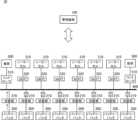
図1は、システム10の一例を概略的に示す。システム10は、管理装置100を備える。管理装置100は、複数の発電部300及び複数の負荷500が接続されたバス400に並列に接続された複数のバッテリーパック200を管理する。管理装置100は、複数のバッテリーパック200の充放電を管理してよい。Figure 1 shows an example of a
システム10は、複数のバッテリーパック200を備えてよい。システム10は、複数の発電部300を備えてもよい。システム10は、複数の負荷500を備えてもよい。The
バッテリーパック200の電池の種類は、任意の種類であってよい。バッテリーパック200は、例えば、負極にリチウムを用いた電池である。バッテリーパック200は、例えば、リチウムイオン電池である。バッテリーパック200は、リチウム金属電池を有してよい。The type of battery in the
バッテリーパック200は、複数のセル202を備える。セル202は、例えば、負極に金属リチウムを用いた電池セルであってよい。The
発電部300は、例えば、太陽光発電を実行する。発電部300による発電手法は、他の発電手法であってもよい。発電部300によって発電された電力によって、バッテリーパック200が充電可能である。複数の発電部300は、バス400に対して並列に接続されてよい。The
負荷500は、バッテリーパック200の電力を消費したり、発電部300によって発電された電力を消費したりする。負荷500は、電力によって動作する任意の装置であってよい。例えば、システム10が飛行体に搭載される場合、負荷500は、プロペラやエレベータ等の飛行体の飛行に関する装置であってよい。The
本実施形態に係る管理装置100は、複数のバッテリーパック200の劣化を抑えるように、複数のバッテリーパック200の充放電を管理してよい。The
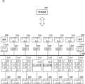
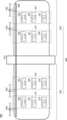
図2は、システム10の一例を概略的に示す。図2に示す例において、複数のバッテリーパック200のそれぞれは、バス400に対するバッテリーパック200の接続のオンオフを切り替える切替部210を介してバス400に接続されている。バス400には、複数の切替部210が並列に接続されており、複数の切替部210のそれぞれに複数のバッテリーパック200のそれぞれが接続されている。また、複数のソーラーセル310が、MPPT(Maximum Power Point Tracking)320を介してバス400に接続されている。ソーラーセル310は、発電部300の一例であってよい。また、複数の負荷500が、コントローラ510を介してバス400に接続されている。ここでは、バス400の左側に配置された左側の負荷500と、バス400の右側に配置された右側の負荷500とを例示している。2 is a schematic diagram of an example of the
バッテリーパック200を区別して説明する場合、左側から右側に向かって、バッテリーパックA、バッテリーパックB、バッテリーパックC、バッテリーパックD、バッテリーパックE、バッテリーパックF、バッテリーパックG、バッテリーパックHと記載する場合がある。切替部210を区別して説明する場合、左側から右側に向かって、切替部A、切替部B、切替部C、切替部D、切替部E、切替部F、切替部G、切替部Eと記載する場合がある。When describing the battery packs 200, they may be described from left to right as battery pack A, battery pack B, battery pack C, battery pack D, battery pack E, battery pack F, battery pack G, and battery pack H. When describing the switching
図3は、システム10における充電時の電流の流れの一例を概略的に示す。図3に例示するように、管理装置100は、複数のソーラーセル310によって発電された電力によって、複数のバッテリーパック200を同時に充電するように、複数のバッテリーパック200のバス400に対する電気的な接続を制御してよい。管理装置100は、例えば、複数のソーラーセル310による発電が開始された場合に、すべてのバッテリーパック200がバス400に電気的に接続されるように、すべての切替部210を制御する。Figure 3 shows a schematic example of a current flow during charging in the
図4は、システム10における放電時の電流の流れの一例を概略的に示す。管理装置100は、複数のバッテリーパック200のすべてが放電する場合と比較して、複数のバッテリーパック200のそれぞれの放電レートが高くなるように、複数のバッテリーパック200に交互に放電させるように複数の切替部210を制御してよい。Figure 4 shows an example of a current flow during discharging in the
管理装置100は、例えば、複数のバッテリーパック200を1つずつ順番に放電させるように複数の切替部210を制御する。管理装置100は、例えば、バッテリーパックA、バッテリーパックB、バッテリーパックC、バッテリーパックD、バッテリーパックE、バッテリーパックF、バッテリーパックG、バッテリーパックHの順番を繰り返して放電させるように複数の切替部210を制御する。また、管理装置100は、例えば、複数のバッテリーパック200のうち、より電圧が高いバッテリーパック200を優先して順番に放電させるように複数の切替部210を制御する。このように、8つのバッテリーパック200に交互に放電させることによって、8つのバッテリーパック200の全てが放電する場合と比較して、バッテリーパック200の放電レートを8倍にすることができる。The
管理装置100は、状況に応じて、複数のバッテリーパック200に対する充電と放電を切り替えるが、例えば、充電のために、すべてのバッテリーパック200をバス400に電気的に接続した状態にしたときに、複数のバッテリーパック200のうちの、電圧が最大のバッテリーパック200と電圧が最小のバッテリーパック200との電圧の差が大きいと、前者から後者に電流が流れて後者の充電レートが速くなってしまい、後者の劣化を早めてしまうことになり得る。The
管理装置100は、複数のバッテリーパック200のうち、電圧が最大のバッテリーパック200と、電圧が最小のバッテリーパック200との電圧の差が予め定められた電圧閾値より大きくならないように、複数のバッテリーパック200に交互に放電させるように複数の切替部210を制御してよい。言い換えると、管理装置100は、複数のバッテリーパック200のうち、残容量が最大のバッテリーパック200と、残容量が最小のバッテリーパック200との残容量の差が予め定められた残容量閾値より大きくならないように、複数のバッテリーパック200に交互に放電させるように複数の切替部210を制御してよい。The
例えば、管理装置100は、まず、複数のバッテリーパック200のうち、電圧が最大のバッテリーパック200(第1のバッテリーパック200と記載する場合がある。)の放電を開始させる。管理装置100は、第1のバッテリーパック200の電圧と、複数のバッテリーパック200のうちの他の複数のバッテリーパック200のうちの電圧が最大のバッテリーパック200(第2のバッテリーパック200と記載する場合がある。)との差が電圧閾値より大きくなる前に、第2のバッテリーパック200の放電を開始させる。管理装置100は、第2のバッテリーパック200の放電を開始させてから予め定められた時間が経過した後、第1のバッテリーパック200の放電を停止させる。このような制御を繰り返すことによって、複数のバッテリーパック200のうち、電圧が最大のバッテリーパック200と、電圧が最小のバッテリーパック200との電圧の差が予め定められた電圧閾値より大きくならないようにできる。なお、当該予め定められた時間は、例えば、0.01~1秒程度であってよい。第2のバッテリーパック200の放電を開始させてから予め定められた時間が経過した後、第1のバッテリーパック200の放電を停止させるようにすることで、放電が途切れないようにできる。For example, the
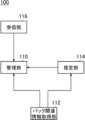
図5は、管理装置100の機能構成の一例を概略的に示す。管理装置100は、管理部110、パック関連情報取得部112、推定部114、及び受信部116を備えてよい。なお、管理装置100がこれらの全てを備えることは必須とは限らない。Figure 5 shows an example of the functional configuration of the
管理部110は、複数のバッテリーパック200のすべてが放電する場合と比較して、複数のバッテリーパック200のそれぞれの放電レートが高くなるように、複数のバッテリーパック200に交互に放電させるように複数の切替部210を制御する。The
管理部110は、複数のバッテリーパック200のうち、電圧が最大のバッテリーパック200と、電圧が最小のバッテリーパック200との電圧の差が予め定められた電圧閾値より大きくならないように、複数のバッテリーパック200に交互に放電させるように複数の切替部210を制御してよい。The
例えば、管理部110は、まず、複数のバッテリーパック200のうち、電圧が最大のバッテリーパック200(第1のバッテリーパック200と記載する場合がある。)の放電を開始させる。次に、管理部110は、第1のバッテリーパック200の電圧と、複数のバッテリーパック200のうちの他の複数のバッテリーパック200のうちの電圧が最大のバッテリーパック200(第2のバッテリーパック200と記載する場合がある。)との差が予め定められた電圧閾値より大きくなる前に、第2のバッテリーパック200の放電を開始させる。そして、管理部110は、第2のバッテリーパック200の放電を開始させてから予め定められた時間が経過した後、第1のバッテリーパック200の放電を停止させる。管理部110は、このような制御を繰り返すことによって、複数のバッテリーパック200に順番に放電させる。For example, the
管理部110は、複数のソーラーセル310によって発電された電力によって、複数のバッテリーパック200を同時に充電するように、複数のバッテリーパック200のバス400に対する電気的な接続を制御してよい。例えば、管理部110は、複数のソーラーセル310によって発電された電力によって、複数のバッテリーパック200を同時に充電するように、複数の切替部210を制御する。The
管理部110は、複数のソーラーセル310によって発電された電力によって複数のバッテリーパック200を充電する場合に、ソーラーセル310からのバス400に対する電圧が、複数のバッテリーパック200のうちの電圧が最大のバッテリーパック200の電圧と、電圧が最小のバッテリーパック200の電圧との間になるように管理してよい。管理部110は、複数のMPPT320を制御することによって、ソーラーセル310からのバス400に対する電圧が、複数のバッテリーパック200のうちの電圧が最大のバッテリーパック200の電圧と、電圧が最小のバッテリーパック200の電圧との間になるように管理してよい。When charging the multiple battery packs 200 with power generated by the multiple
パック関連情報取得部112は、複数のバッテリーパック200のそれぞれについて、バッテリーパック200に関連するパック関連情報を取得する。例えば、パック関連情報取得部112は、複数のバッテリーパック200のそれぞれに対して配置されたセンサによって検知された情報を、パック関連情報として、当該センサから取得する。The pack-related
パック関連情報は、バッテリーパック200のOCV(Open Circuit Voltage:開回路電圧)を含んでよい。パック関連情報は、バッテリーパック200のCCV(Closed Circuit Voltage:閉回路電圧)を含んでよい。パック関連情報は、バッテリーパック200のDCIR(Direct Current Internal Resistence:直流内部抵抗)を含んでよい。パック関連情報は、バッテリーパック200のSOH(State of Health)を含んでよい。パック関連情報は、バッテリーパック200のSOC(State Of Charge)を含んでよい。パック関連情報は、バッテリーパック200の電流値を含んでよい。パック関連情報は、バッテリーパック200の放電時間を含んでよい。パック関連情報は、バッテリーパック200の積算容量を含んでよい。パック関連情報は、バッテリーパック200の温度を含んでよい。The pack-related information may include the OCV (Open Circuit Voltage) of the
推定部114は、パック関連情報取得部112が取得したパック関連情報に基づいて、バッテリーパック200の状態を推定する。推定部114は、既存のBMS(Battery Management System)において用いられている推定方法を用いて、推定を行ってよい。The
例えば、推定部114は、バッテリーパック200のSOCとDCIRの関係を記憶しておき、記憶しているDCIRと、SOHと、電流値と、放電時間と、CCVと、積算容量からバッテリーパック200のOCVを推定する。For example, the
また、例えば、推定部114は、まず、放電開始前のOCVと、電流値と、放電時間と、CCVと、積算容量と、温度とから、放電開始前のSOC及びSOHを推定する。次に、推定部114は、そのデータを用いて、予め記憶しているデータベースから、現在のDCIRを推定する。そして、推定部114は、推定した現在のDCIRと、CCVと、電流値とから、現在のOCVを推定する。For example, the
管理部110は、パック関連情報取得部112が取得した複数のバッテリーパック200のそれぞれのOCVに基づいて、複数のバッテリーパック200のうちの電圧が最大のバッテリーパック200と、電圧が最小のバッテリーパック200との電圧の差が予め定められた電圧閾値より大きくならないように、複数のバッテリーパック200に交互に放電させるように複数の切替部210を制御してよい。Based on the OCV of each of the battery packs 200 acquired by the pack-related
また、管理部110は、推定部114が推定した複数のバッテリーパック200のそれぞれのOCVに基づいて、複数のバッテリーパック200のうちの電圧が最大のバッテリーパック200と、電圧が最小のバッテリーパック200との電圧の差が予め定められた電圧閾値より大きくならないように、複数のバッテリーパック200に交互に放電させるように複数の切替部210を制御してよい。In addition, the
管理部110は、電圧が最大のバッテリーパック200から、電圧が最小のバッテリーパック200への充電レートが予め定められた充電レート閾値より早くならないような電圧閾値を予め設定してよい。充電レート閾値は、例えば、0.3C以下であってよく、より望ましくは、0.2C以下であってよい。The
例えば、5kWh(15Ah)で、DICRが最低1.87Ω、平均1.99Ω、電圧が270~396Vのバッテリーパック200を用いていた場合において、DCIRを2Ωとし、充電で3Aの0.2Cにするには、電圧が最大のバッテリーパック200と電圧が最小のバッテリーパック200との電圧差<(0.2(C)×15(Ah)×2(Ω)=6V)となり、電圧閾値は6Vとなる。この場合、管理部110は、電圧が最大のバッテリーパック200(第1のバッテリーパック200と記載する)の放電を開始させた後、当該第1のバッテリーパック200の電圧が、次に電圧が高いバッテリーパック200(第2のバッテリーパック200と記載する)の電圧よりも6V以上低くなる前に、当該第2のバッテリーパック200の放電を開始させ、予め定められた時間が経過した後に、第1のバッテリーパック200の放電を停止させる。For example, in the case of using a
また、0.3Cにするには、電圧が最大のバッテリーパック200と電圧が最小のバッテリーパック200との電圧差<(0.3(C)×15(Ah)×2(Ω)=9V)となり、電圧閾値は9Vとなる。この場合、管理部110は、第1のバッテリーパック200の放電を開始させた後、当該第1のバッテリーパック200の電圧が、第2のバッテリーパック200の電圧よりも9V以上低くなる前に、当該第2のバッテリーパック200の放電を開始させ、予め定められた時間が経過した後に、第1のバッテリーパック200の放電を停止させる。To achieve 0.3C, the voltage difference between the
管理部110は、例えば、ソーラーセル310による発電量が増加して余剰の発電量がある場合に、複数のバッテリーパック200が充電される充電レートが充電レート閾値より早くならないように、ソーラーセル310によって発電された電力を消費するように管理してもよい。例えば、管理部110は、ソーラーセル310によって発電された電力によって複数のバッテリーパック200が充電される充電レートが充電レート閾値より早くならないように、ソーラーセル310によって発電された電力を、負荷500が消費するようにコントローラ510を制御する。For example, when the amount of power generated by the
管理部110は、複数のバッテリーパック200のうち、放電させているバッテリーパック200の放電レートが、予め定められた放電レート閾値より遅い時間が予め定められた時間継続した場合に、放電させているバッテリーパック200の電力消費量を増加させるように管理してもよい。例えば、管理部110は、バッテリーパック200の電力を負荷500が消費するようにコントローラ510を制御する。当該予め定められた時間は、秒単位又は分単位で任意に設定可能であってよい。これにより、放電レートが低い状態が長時間継続することによって、バッテリーパック200の劣化が早まってしまうことを防止できる。放電レート閾値は、0.3C~2.0Cであってよく、より望ましくは、0.4C~1.0Cであってよい。The
下記表1は、負極に金属リチウムを用いた電池セルを有するバッテリーパック200の、様々な放電レート及び充電レート毎の劣化度合を実験した実験結果を示す。実験は、放電レート及び充電レートの組み合わせ毎に、複数回行い、初期容量の80%を維持したのが平均で250サイクル以上である場合を「◎」、初期容量の80%を維持したのが平均で200サイクル以上250サイクル未満である場合を「〇」、平均で180サイクル以下である場合を「×」としている。当該実験結果は、例えば、複数のバッテリーパック200のそれぞれについて、0.3Cの放電レートで放電し、0.1Cの充電レートで充電することを繰り返した結果、初期容量の80%を維持したのが、平均で200サイクル以上250サイクル未満であったことを示す。また、例えば、複数のバッテリーパック200のそれぞれについて、0.5Cの放電レートで放電し、0.2Cの充電レートで充電することを繰り返した結果、初期容量の80%を維持したので、平均で250サイクル以上であったことを示す。Table 1 below shows the results of an experiment conducted to examine the degree of deterioration for various discharge and charge rates of a

表1に示すように、放電レートは0.3C~2.0Cが望ましく、0.4C~1.0Cがさらに望ましい。充電レートは、0.3C以下が望ましく、0.2C以下がさらに望ましい。As shown in Table 1, the discharge rate is preferably 0.3C to 2.0C, and more preferably 0.4C to 1.0C. The charge rate is preferably 0.3C or less, and more preferably 0.2C or less.
受信部116は、外部から各種情報を受信する。受信部116は、例えば、管理部110に対する制御指示を受信する。管理部110は、受信部116が受信した制御指示に従って、複数の切替部210を制御してよい。受信部116は、例えば、システム10が位置するエリアの天候情報を受信する。管理部110は、受信部116が受信した天候情報に基づいて、複数の切替部210を制御してもよい。The receiving
図6は、システム10における放電時の電流の流れの他の一例を概略的に示す。管理部110は、複数のバッテリーパック200を2つ以上ずつ順番に放電させるように複数の切替部210を制御してもよい。例えば、管理部110は、複数のバッテリーパック200を2つずつ順番に放電させるように制御する。また、例えば、管理部110は、複数のバッテリーパック200を3つずつ順番に放電させるように制御する。また、例えば、管理部110は、複数のバッテリーパック200を4つずつ順番に放電させるように制御する。これらは例示であり、管理部110は、さらに多くの数ずつ順番に放電させるように制御してもよい。Figure 6 shows a schematic diagram of another example of the current flow during discharging in the
管理部110は、複数の左側のバッテリーパック200及び複数の右側のバッテリーパック200について、左右の電圧差が大きく偏らないような制御を実行してよい。The
例えば、管理部110は、複数の左側のバッテリーパック200及び複数の右側のバッテリーパック200について、左側の1つ、右側の1つ、左側の1つ、右側の1つ、というように、左側と右側を交互に放電させる。左側のバッテリーパック200と右側のバッテリーパック200とを交互に放電させることによって、左右の電圧差が大きくならないようにできる。For example, the
このとき、管理部110は、複数の左側のバッテリーパック200及び複数の右側のバッテリーパック200の位置関係を考慮して、左側と右側を交互に放電させてよい。例えば、管理部110は、左側のバッテリーパック200、当該左側のバッテリーパック200に位置的に対応する右側のバッテリーパック200、次の左側のバッテリーパック200、当該左側のバッテリーパック200に位置的に対応する右側のバッテリーパック200、というように、左側と右側を交互に放電させる。位置的に対応するとは、例えば、左右対称の位置であることであってよい。例えば、管理部110は、第1のバッテリーパック200を放電させた後、左右対称の位置の第8のバッテリーパック200を放電させ、第2のバッテリーパック200を放電させた後、左右対称の位置の第7のバッテリーパック200を放電させ、第3のバッテリーパック200を放電させた後、左右対称の位置の第6のバッテリーパック200を放電させ、第4のバッテリーパック200を放電させた後、左右対称の位置の第5のバッテリーパック200を放電させる。At this time, the
また、例えば、管理部110は、複数の左側のバッテリーパック200及び複数の右側のバッテリーパック200の位置関係を考慮せずに、左側と右側を交互に放電させてもよい。例えば、管理部110は、第1のバッテリーパック200を放電させた後、第5から第8のバッテリーパック200のいずれかを放電させ、第2の放電させた後、第5から第8のうちの残りの3つのうちのいずれかを放電させ、第3のバッテリーパック200を放電させた後、第5から第8のうちの残りの2つのうちのいずれかを放電させ、第4のバッテリーパック200を放電させた後、第5から第8のうちの残りの1つのうちを放電させる。Also, for example, the
また、例えば、管理部110は、複数の左側のバッテリーパック200及び複数の右側のバッテリーパック200のそれぞれの1つずつに、順番に放電させるように複数の切替部210を制御してもよい。このとき、管理部110は、複数の左側のバッテリーパック200及び複数の右側のバッテリーパック200の位置関係を考慮して、複数の左側のバッテリーパック200及び複数の右側のバッテリーパック200のそれぞれの1つずつに、順番に放電させるように複数の切替部210を制御してよい。例えば、管理部110は、複数の左側のバッテリーパック200及び複数の右側のバッテリーパック200のそれぞれの1つずつに、左右対称に、順番に放電させるように複数の切替部210を制御してよい。For example, the
管理部110は、例えば、第1のバッテリーパック200及び第8のバッテリーパック200、第2のバッテリーパック200及び第7のバッテリーパック200、第3のバッテリーパック200及び第6のバッテリーパック200、第4のバッテリーパック200及び第5のバッテリーパック200、の順番に放電させるように複数の切替部210を制御する。例えば、第1のバッテリーパック200及び第2のバッテリーパック200に放電を実行させた場合、左側の負荷500への送電経路は短くなるが、右側の負荷500への送電経路が長くなり、送電効率が悪い。それに対して、左右対称に放電させることによって、左側の負荷500及び右側の負荷500の一方に対する送電経路が長くなってしまうことを防止でき、送電効率の低下を抑制できる。なお、この場合において、管理部110は、第1のバッテリーパック200及び第8のバッテリーパック200を放電させるときに、第1のバッテリーパック200及び第8のバッテリーパック200を同時に放電させてよく、交互に放電させてもよく、順番に放電させてもよい。The
管理部110は、第1のバッテリーパック200及び第8のバッテリーパック200の組、第2のバッテリーパック200及び第7のバッテリーパック200の組、第3のバッテリーパック200及び第6のバッテリーパック200の組、及び第4のバッテリーパック200及び第5のバッテリーパック200の組について、より電圧が高い組を優先して放電させるように制御してもよい。例えば、管理部110は、複数の組のそれぞれについて、より電圧が高いバッテリーパック200を特定し、特定したバッテリーパック200の電圧がより高い組を優先して放電させる。また、例えば、管理部110は、複数の組のうち、平均の電圧がより高い組を優先して放電させる。The
また、管理部110は、複数の左側のバッテリーパック200及び複数の右側のバッテリーパック200の位置関係を考慮せずに、複数の左側のバッテリーパック200及び複数の右側のバッテリーパック200のそれぞれの1つずつに、順番に放電させるように複数の切替部210を制御してもよい。例えば、管理部110は、複数の左側のバッテリーパック200及び複数の右側のバッテリーパック200の任意の組み合わせ毎に、順番に放電させるように複数のバッテリーパック200を管理してもよい。例えば、第1のバッテリーパック200に対して、第5のバッテリーパック200~第8のバッテリーパック200のいずれかを組み合わせ、第2のバッテリーパック200に対して、第5のバッテリーパック200~第8のバッテリーパック200の残りの3つのうちのいずれかを組み合わせ、第3のバッテリーパック200に対して、第5のバッテリーパック200~第8のバッテリーパック200の残りの2つのうちのいずれかを組み合わせ、第4のバッテリーパック200に対して、第5のバッテリーパック200~第8のバッテリーパック200のうちの残りのバッテリーパック200を組み合わせて、組み合わせ毎に順番に放電させるように管理する。In addition, the
管理部110は、例えば、複数の組のそれぞれについて、より電圧が高いバッテリーパック200を特定し、電圧が高い順に組の順番を決定する。そして、管理部110は、複数のバッテリーパック200のうち、電圧が最大のバッテリーパック200と、電圧が最小のバッテリーパック200との電圧の差が電圧閾値より大きくならないように、決定した順番に従って、適宜組を切り替えながら、放電させる。For example, the
図7は、複数の切替部210の構成の一例を概略的に示す。本実施形態に係るシステム10において、複数の切替部210のうちの少なくともいずれかは、接続されたバッテリーパック200からバス400に対して電流が流れる放電状態、バス400からバッテリーパック200に対して電流が流れる充電状態、及びバス400とバッテリーパック200との間で電流が流れない切断状態を切り替え可能な、FET211(放電用FETと記載する場合がある)及びFET212(充電用FETと記載する場合がある)を有する。Figure 7 shows an example of the configuration of the multiple switching
放電用FET及び充電用FETは、両方ともP型のFETであってよい。放電用FET及び充電用FETは、両方ともN型のFETであってもよい。管理部110は、放電用FET及び充電用FETを制御することによって、充電状態、放電状態、及び切断状態を切り替える。放電用FET及び充電用FETは、充電状態、放電状態、及び切断状態を切り替え可能であれば、どのように構成されてもよい。The discharge FET and the charge FET may both be P-type FETs. The discharge FET and the charge FET may both be N-type FETs. The
図7に示す例では、複数の切替部210のすべてが、放電用FET及び充電用FETを有する。コンタクタが機械的にオンオフを制御する一方、FETは電気制御によってオンオフを制御する。したがって、コンタクタを採用する場合と比較して、FETを採用することによって、オンオフの切り替えに対する耐性を向上させることができる。また、複数の切替部210のうちの一部又はすべてにコンタクタを追加する構成と比較して、全体の重量を低減することができる。In the example shown in FIG. 7, all of the multiple switching
管理部110は、複数のバッテリーパック200を交互に放電させる場合において、上述したように、一のバッテリーパック200を放電させている状態で、次のバッテリーパック200の放電を開始させ、予め定められた時間が経過した後、当該一のバッテリーパック200の放電を停止させるようにしてよい。これにより、放電が途切れないようにできる。When discharging a plurality of battery packs 200 alternately, as described above, the
FETは、コンタクタと比較して耐電圧が低いので、例えば、システム10に対して雷が直撃するなどの理由によって、過電圧が加わった場合に、故障してしまうことが懸念される。FETは、雷等で壊れると、電流をオフにできない(切断状態にならない)パターン(パターンAと記載する場合がある)、電流が流れなくなるパターン(パターンBと記載する場合がある。)、及び半分壊れるパターン(パターンCと記載する場合がある。)がある。パターンAの場合は、バス400とバッテリーパック200とが常に電気的に接続された状態となってしまい、バッテリーパック200の劣化は早まるが、システム10の動作に大きな影響はない。しかし、パターンBの場合は、バッテリーパック200の電力を利用できなくなり、システム10の動作に大きな影響がある。また、パターンCの場合、抵抗が高い状態で電流が流れることになり、発熱し、場合によっては発火にまで至るおそれがある。他の様々な機構を取り入れることによって、このような問題の発生を防止したり、低減したりすることはできるが、複数の切替部210の構成によっても対応することが望ましい。FETs have a lower withstand voltage than contactors, so there is concern that they may break down if an overvoltage is applied due to, for example, a direct lightning strike on the
図8は、複数の切替部210の構成の他の一例を概略的に示す。図8に示すように、システム10は、複数の切替部210のうちの一部が、放電用FET及び充電用FETを有し、複数の切替部210のうちの他の一部が、接続されたバッテリーパック200とバス400との間の電流のオンオフを切り替えるコンタクタ214を有するように構成されてもよい。Figure 8 shows another example of the configuration of the multiple switching
このように、一部の切替部210をコンタクタ214によって構成することによって、仮にシステム10に対して過電圧が加わった場合であっても、一部の切替部210が破壊されないようにでき、少なくとも最低限の機能を維持することを可能にできる。In this way, by configuring some of the switching
管理部110は、充電時において、放電用FET及び充電用FETによって構成されている切替部210を充電状態とし、コンタクタ214によって構成されている切替部210のコンタクタ214をオンにすることによって、複数のバッテリーパック200のすべてを充電するようにしてよい。管理部110は、放電時において、コンタクタ214によって構成されている切替部210のコンタクタ214をオンにし、かつ、放電用FET及び充電用FETによって構成されている複数の切替部210を交互に放電状態にしてよい。管理部110は、当該放電時において、上述したように、放電用FET及び充電用FETによって構成されている切替部210のうちの一の切替部210を放電状態にしている状態で、次の切替部210を放電状態にし、予め定められた時間が経過した後、一の切替部210を切断状態にするようにしてよい。During charging, the
また、管理部110は、当該放電時において、放電用FET及び充電用FETによって構成されている複数の切替部210について、同時に放電状態にならないように交互に放電状態にしてもよい。放電時に、コンタクタ214によって構成されている切替部210のコンタクタ214をオンのまま維持することによって、放電用FET及び充電用FETによって構成されている切替部210について、同時に放電状態にならないように交互にオンにしても、放電が途切れないようにできる。In addition, during the discharge, the
放電用FET及び充電用FETを有する切替部210と、コンタクタ214を有する切替部210との割合は、任意の割合であってよい。例えば、複数の切替部210のうちの1つの切替部210をコンタクタ214によって構成することによって、仮にシステム10に対して過電圧が加わった場合でも、少なくとも1つの切替部210及びバッテリーパック200の機能を維持することができる。また、例えば、複数の切替部210のうちの2つの切替部210をコンタクタ214によって構成することによって、冗長性を持たせることができる。The ratio of switching
図8に示す例では、8つの切替部210のうち、6つの切替部210が放電用FET及び充電用FETを有し、2つの切替部210がコンタクタ214を有する。管理部110は、充電時において、6つの切替部210を充電状態とし、2つの切替部210のコンタクタ214をオンにすることによって、複数のバッテリーパック200のすべてを充電するようにしてよい。管理部110は、放電時において、2つのコンタクタ214をオンにし、かつ、6つの切替部210を交互に放電状態にしてよい。管理部110は、当該放電時において、上述したように、6つの切替部210のうちの一の切替部210を放電状態にしている状態で、次の切替部210を放電状態にし、予め定められた時間が経過した後、一の切替部210を放電状態にするようにしてよい。また、管理部110は、6つの切替部210について、同時に放電状態にならないように交互に放電状態にしてもよい。In the example shown in FIG. 8, of the eight switching
図9は、複数の切替部210の構成の他の一例を概略的に示す。図9に示すように、システム10は、複数の切替部210のうちの一部が、放電用FET及び充電用FETを有し、複数の切替部210のうちの他の一部が、バス400に接続されたコンタクタ214と、コンタクタ214とバッテリーパック200との間に直列に接続された放電用FET及び充電用FETとを有するように構成されてもよい。Figure 9 shows another example of the configuration of the multiple switching
管理部110は、予め定められた条件が満たされている間、複数の切替部210のうちの他の一部のコンタクタ214をオフの状態で維持してよい。管理部110は、例えば、受信部116が外部から受信したシステム10が位置するエリアの天候情報に基づいて、予め定められた条件が満たされているか否かを判定する。天候情報は、各地の現状の天候を示してよい。天候情報は、各地の天候の予報を示してもよい。例えば、管理部110は、システム10が、雷が発生するエリアに位置する間、コンタクタ214をオフの状態で維持する。管理部110は、システム10が、雷が発生するエリアに位置しない場合、コンタクタ214をオンの状態としてよい。管理部110は、コンタクタ214をオフの状態に維持している場合、放電時に、複数の切替部210のうちの放電用FET及び充電用FETを有する一部の複数の切替部210を交互に放電状態にしてよく、コンタクタ214をオンの状態にしている場合は、放電時に、複数の切替部210のすべてについて、交互に放電状態にしてよい。雷が発生するエリアとは、現に雷が発生しているエリアであってよく、雷が発生することが予想されているエリアであってもよい。The
図9に示す例では、雷が発生するエリアにおいては、コンタクタ214をオフにするので、万が一雷が落ちて、複数の切替部210のうちの一部について、FETが故障して電流が流れなくなっても、複数の切替部210のうちの他の一部については、FETを保護することができる。図9に示す例では、雷が発生しないエリアにおいては、コンタクタ214をオンにするので、総合的には、雷が発生するエリアにおいては、コンタクタ214、放電用FET及び充電用FETによって構成されている切替部210の放電用FET及び充電用FETを保護することができ、雷が発生するエリア以外のエリアにおいては、コンタクタ214ではなく、放電用FET及び充電用FETにより切り替えを行うことによって、切り替えへの耐性を高めることができる。In the example shown in FIG. 9, the
図9に示す例では、8つの切替部210のうち、6つの切替部210が放電用FET及び充電用FETによって構成され、2つの切替部210がコンタクタ214、放電用FET及び充電用FETによって構成されている。管理部110は、システム10が、雷が発生するエリアに位置する間、2つの切替部210について、コンタクタ214をオフに維持し、システム10が、雷が発生するエリアに位置しない場合、2つの切替部210について、コンタクタ214をオンにしてよい。そして、管理部110は、システム10が、雷が発生するエリアに位置する場合、放電時に、6つの切替部210のすべてについて、交互に放電状態にしてよく、システム10が、雷が発生するエリアに位置しない場合、放電時に、8つの切替部210を交互に放電状態にしてよい。In the example shown in FIG. 9, of the eight switching
コンタクタには、制御電流が加わったときにオフになるタイプと、制御電流が加わったときにオンになるタイプとがある。本実施形態に係るコンタクタ214は、制御電流が加わったときにオフになるタイプであってよい。管理部110は、システム10が、雷が発生するエリアに位置する場合、2つの切替部210のコンタクタ214に制御電流を加えてオフする。システム10に万が一雷が落ちた場合であって、6つの切替部210のFET211及びFET212に電流が流れなくなった場合であっても、2つの切替部210のFET211及びFET212は保護することができる。また、雷によって電流系統が故障し、電気の供給がストップした際に、コンタクタ214への制御電流がストップして、コンタクタ214がオンになり、2つの切替部210に接続されている2つのバッテリーパック200からの電力は、負荷500等に供給されることになり、システム10の少なくとも最低限の機能を維持することができる。There are two types of contactors: one that turns off when a control current is applied, and one that turns on when a control current is applied. The
放電用FET及び充電用FETにより構成される切替部210と、コンタクタ214、電用FET及び充電用FETにより構成される切替部210との割合は、任意の割合であってよい。例えば、複数の切替部210のうちの1つの切替部210をコンタクタ214、放電用FET及び充電用FETによって構成してよく、複数の切替部210のうちの2つの切替部210をコンタクタ214、放電用FET及び充電用FETによって構成してよい。The ratio of switching
また、複数の切替部210のすべてが、コンタクタ214、放電用FET及び充電用FETによって構成されてもよい。これにより、安全性を更に高めることができる。この場合、管理部110は、システム10が、雷が発生するエリアに位置する間、複数の切替部210のうちの一部の切替部210のコンタクタ214のみをオンとし、その他の切替部210のコンタクタ214をオフの状態で維持してよい。管理部110は、システム10の機能を最低限維持するために必要な数の切替部210のコンタクタ214のみをオンとし、それ以外の切替部210のコンタクタ214をオフの状態で維持してよい。複数の切替部210のすべてのコンタクタ214は、制御電流が加わったときにオフになるタイプであってよく、管理部110は、システム10が、雷が発生するエリアに位置する間、複数の切替部210のうちの一部の切替部210のコンタクタ214のみをオンとし、その他の切替部210のコンタクタ214に制御電流を加えてオフの状態で維持してよい。All of the multiple switching
図10は、コンタクタ214、放電用FET及び充電用FETによって構成される切替部210の構成の一例を概略的に示す。図10に例示するように、切替部210は、バス400に接続されたコンタクタ214と、コンタクタ214とバッテリーパック200との間に直列に接続された放電用FET及び充電用FETとを有してよい。管理部110は、例えば、システム10が、雷が発生するエリアに位置する間、コンタクタ214をオフに維持する。これにより、システム10に雷が落ちても、FET211、FET212、及びバッテリーパック200に対して電気が流れないようにでき、FET211、FET212、及びバッテリーパック200を保護することができる。管理部110は、何らかの理由によって、FET211及びFET212の少なくともいずれかに不具合が発生した場合にも、コンタクタ214をオフにしてよい。FET211及びFET212が、仮に、故障したパターンCとなった場合、FET211及びFET212に電気が流れると、発熱して、場合によっては発火する可能性があるが、コンタクタ214をオフにすることによって、それを防ぐことができる。10 is a schematic diagram showing an example of the configuration of the
上記実施形態では、コンタクタ214が、なお、コンタクタ214は、制御電流が加わったときにオフになるタイプである場合について説明したが、これに限らない。コンタクタ214は、制御電流が加わったときにオンになるタイプであってもよい。In the above embodiment, the
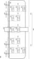
図11は、システム10を搭載した飛行機600の一例を概略的に示す。飛行機600は、飛行体の一例であってよい。図11では、複数のバッテリーパック200の例として、バッテリーパック220からバッテリーパック231を図示している。図11に示す例において、バッテリーパック220からバッテリーパック224が、翼部620の左翼部622の中に配置され、バッテリーパック225及びバッテリーパック226が機体610の中に配置され、バッテリーパック227からバッテリーパック231が翼部620の右翼部624の中に配置されている。Figure 11 shows a schematic diagram of an example of an
図11では、管理装置100と、複数の切替部210と、複数の発電部300と、バッテリーパック220からバッテリーパック231のバス400への配線の図示を省略している。また、複数の切替部210がすべて放電用FET及び充電用FETによって構成されている場合について主に例に挙げて説明する。In FIG. 11, the
管理装置100は、例えば、飛行機600の機体610の中に配置される。発電部300は、例えば、翼部620の上面に配置される。バッテリーパック220からバッテリーパック231は、バス400に対して並列に接続される。プロペラ630は、負荷500の一例である。The
ここでは、管理部110が、複数のバッテリーパック200を2つずつ順番に放電させる場合における順番について説明する。管理部110は、左右対称に配置されたグループ901及びグループ905のそれぞれから1つずつを選択して放電させ、グループ902及びグループ904のそれぞれから1つずつを選択して放電させ、グループ903の2つを選択して放電させるという順番を繰り返してよい。左右対称に配置された2つのグループのそれぞれから1つずつを選択する順番は、前後方向が一致するように選択しても、前後方向が一致しないように選択してもよい。例えば、前者の場合、管理部110は、バッテリーパック220及びバッテリーパック229、バッテリーパック221及びバッテリーパック230、バッテリーパック222及びバッテリーパック231の順番に放電させ、バッテリーパック223及びバッテリーパック227、バッテリーパック224及びバッテリーパック228の順番に放電させ、バッテリーパック225及びバッテリーパック226に放電させる。Here, the order in which the
複数の切替部210のうちの一部の切替部210をコンタクタ214によって構成する場合、例えば、バッテリーパック225及びバッテリーパック226に接続される切替部210を、コンタクタ214によって構成してよい。When some of the multiple switching
図12は、システム10を搭載した飛行機600の他の一例を概略的に示す。ここでは、図11と異なる点を主に説明する。図12に示す例において、バッテリーパック220からバッテリーパック225が翼部620の左翼部622に配置され、バッテリーパック226からバッテリーパック231が翼部620の右翼部624に配置されている。Figure 12 shows a schematic diagram of another example of an
管理部110は、左右対称に配置されたグループ901及びグループ904のそれぞれから1つずつを選択して放電させ、グループ902及びグループ903のそれぞれから1つずつを選択して放電させるという順番を繰り返してよい。左右対称に配置された2つのグループのそれぞれから1つずつを選択する順番は、前後方向が一致するように選択しても、前後方向が一致しないように選択してもよい。例えば、前者の場合、管理部110は、バッテリーパック220及びバッテリーパック229、バッテリーパック221及びバッテリーパック230、バッテリーパック222及びバッテリーパック231の順番に放電させ、バッテリーパック223及びバッテリーパック226、バッテリーパック224及びバッテリーパック227、バッテリーパック225及びバッテリーパック228の順に放電させる。The
図13は、システム10を搭載した飛行機600の他の一例を概略的に示す。ここでは、図11と異なる点を主に説明する。図13に示す例において、バッテリーパック220からバッテリーパック226が飛行機600の左側に配置され、バッテリーパック227から240が飛行機600の中心部に配置され、バッテリーパック231からバッテリーパック237が飛行機600の右側に配置されている。Figure 13 shows a schematic diagram of another example of an
管理部110は、左右対称に配置されたグループ901及びグループ905のそれぞれから1つずつを選択して放電させ、グループ902及びグループ904のそれぞれから1つずつを選択して放電させ、グループ903から2つずつ選択して放電させるという順番を繰り返してよい。左右対称に配置された2つのグループのそれぞれから1つずつを選択する順番は、前後方向が一致するように選択しても、前後方向が一致しないように選択してもよい。例えば、前者の場合、管理部110は、バッテリーパック220及びバッテリーパック236、バッテリーパック221及びバッテリーパック237の順番に放電させ、バッテリーパック222及びバッテリーパック231、バッテリーパック223及びバッテリーパック232、バッテリーパック224及びバッテリーパック233、バッテリーパック225及びバッテリーパック234、バッテリーパック226及びバッテリーパック235の順に放電させ、バッテリーパック227及びバッテリーパック228、バッテリーパック229及びバッテリーパック230の順番に放電させる。The
図14は、システム10を搭載した飛行機600の他の一例を概略的に示す。ここでは、図11と異なる点を主に説明する。図14に示す例において、バッテリーパック220からバッテリーパック223とバッテリーパック228及びバッテリーパック229と翼部620の左翼部622に配置され、バッテリーパック224からバッテリーパック227が飛行機600の中心部に配置され、バッテリーパック230からバッテリーパック235が翼部620の右翼部624に配置されている。Figure 14 shows a schematic diagram of another example of an
管理部110は、左右対称に配置されたグループ901及びグループ905のそれぞれから1つずつを選択して放電させ、グループ902及びグループ904のそれぞれから1つずつを選択して放電させ、グループ903から2つずつ選択して放電させるという順番を繰り返してよい。左右対称に配置された2つのグループのそれぞれから1つずつを選択する順番は、前後方向が一致するように選択しても、前後方向が一致しないように選択してもよい。例えば、前者の場合、管理部110は、バッテリーパック220及びバッテリーパック234、バッテリーパック221及びバッテリーパック235の順番に放電させ、バッテリーパック222及びバッテリーパック232、バッテリーパック223及びバッテリーパック233の順番に放電させ、バッテリーパック229及びバッテリーパック231、バッテリーパック228及びバッテリーパック230、バッテリーパック226及びバッテリーパック227、バッテリーパック224及びバッテリーパック225の順に放電させる。The
図15は、システム10を搭載したHAPS700の一例を概略的に示す。HAPS700は、地上に向けてビーム702を照射することにより形成した通信エリア704内のユーザ端末30に無線通信サービスを提供する飛行体である。Figure 15 shows an example of a
HAPS700は、機体710、中央部720、プロペラ730、ポッド740、及び太陽電池パネル750を備える。機体710は、翼部712を有する。翼部712は、左翼部714及び右翼部716を含む。The
翼部712の内部に、並列に接続された複数のバッテリーパック200が配置されている。複数のバッテリーパック200のうち、左側の複数のバッテリーパック200が、左翼部714に配置され、右側の複数のバッテリーパック200が、右翼部716に配置されてよい。複数のバッテリーパック200は、複数の切替部210を介してバス400に接続されていてよい。太陽電池パネル750は、MPPT320を介して、バス400に接続されてよい。複数のバッテリーパック200によって放電された電力は、HAPS700が備える各構成によって利用される。例えば、複数のバッテリーパック200によって放電された電力は、プロペラ730のモータによって利用される。プロペラ730のモータは、負荷500の一例であってよい。A plurality of battery packs 200 connected in parallel are arranged inside the
中央部720内には、飛行制御部722及び通信制御部724と、不図示の管理装置100が配置される。飛行制御部722は、複数のバッテリーパック200によって放電された電力を用いて、HAPS700の飛行を制御する。通信制御部724は、複数のバッテリーパック200によって放電された電力を用いて、HAPS700の通信を制御する。A
飛行制御部722は、例えば、プロペラ730の回転を制御することによってHAPS700の飛行を制御する。また、飛行制御部722は、不図示のフラップやエレベータの角度を変更することによってHAPS700の飛行を制御してもよい。飛行制御部722は、GPSセンサ等の測位センサ、ジャイロセンサ、及び加速度センサ等の各種センサを備えて、HAPS700の位置、移動方向、及び移動速度を管理してよい。The
通信制御部724は、SL(Service Link)アンテナを用いて、地上に通信エリア704を形成する。通信制御部724は、SLアンテナを用いて、地上のユーザ端末30とサービスリンクを形成する。SLアンテナは、マルチビームアンテナであってもよい。通信エリア704は、マルチセルであってもよい。The
通信制御部724は、FL(Feeder Link)アンテナを用いて、地上のゲートウェイ40との間でフィーダリンクを形成してよい。通信制御部724は、ゲートウェイ40を介して、ネットワーク20にアクセスしてよい。The
通信制御部724は、衛星通信アンテナを用いて、通信衛星50と通信してよい。通信制御部724は、通信衛星50及び衛星通信局60を介して、ネットワーク20にアクセスしてよい。The
ユーザ端末30は、HAPS700と通信可能であればどのような通信端末であってもよい。例えば、ユーザ端末30は、スマートフォン等の携帯電話である。ユーザ端末30は、タブレット端末及びPC(Personal Computer)等であってもよい。ユーザ端末30は、いわゆるIoT(Internet of Thing)デバイスであってもよい。ユーザ端末30は、いわゆるIoE(Internet of Everything)に該当するあらゆるものを含み得る。The
HAPS700は、例えば、フィーダリンク又は通信衛星50と、サービスリンクとを介して、ネットワーク20とユーザ端末30との通信を中継する。HAPS700は、ユーザ端末30とネットワーク20との通信を中継することによって、ユーザ端末30に無線通信サービスを提供してよい。The
ネットワーク20は、移動体通信ネットワークを含む。移動体通信ネットワークは、3G(3rd Generation)通信方式、LTE(Long Term Evolution)通信方式、5G(5th Generation)通信方式、及び6G(6th Generation)通信方式以降の通信方式のいずれに準拠していてもよい。ネットワーク20は、インターネットを含んでもよい。The
HAPS700は、例えば、通信エリア704内のユーザ端末30から受信したデータをネットワーク20に送信する。また、HAPS700は、例えば、ネットワーク20を介して、通信エリア704内のユーザ端末30宛のデータを受信した場合に、当該データをユーザ端末30に送信する。For example,
HAPS700は、例えば、成層圏において、予め定められた飛行経路を巡回しながら、地上の特定のエリアに通信エリア704を維持する。HAPS700は、日中に太陽電池パネル750によって発電した電力を複数のバッテリーパック200に蓄え、夜間は複数のバッテリーパック200の電力を用いることによって、成層圏の飛行を維持する。HAPS700は、例えば、日中に複数のバッテリーパック200を充電しつつ、上昇して位置エネルギーを蓄え、夜間は、緩やかに下降しつつ、適宜バッテリーパック200の電力を用いてプロペラ730等を稼働させることによって、成層圏の飛行を維持する。HAPS700 maintains a
管理装置800は、複数のHAPS700を管理する。管理装置800は、ネットワーク20及びゲートウェイ40を介して、HAPS700と通信してよい。管理装置800は、ネットワーク20、衛星通信局60、及び通信衛星50を介して、HAPS700と通信してもよい。The
管理装置800は、指示を送信することによってHAPS700を制御する。管理装置800は、通信エリア704によって地上の対象エリアをカバーさせるべく、HAPS700に、対象エリアの上空を旋回させてよい。HAPS700は、例えば、対象エリアの上空を円軌道で飛行しつつ、FLアンテナの指向方向を調整することによってゲートウェイ40との間のフィーダリンクを維持し、SLアンテナの指向方向を調整することによって通信エリア704による対象エリアのカバーを維持する。The
管理装置100の管理部110は、上述したように、複数のバッテリーパック200のうち、電圧が最大のバッテリーパック200と、電圧が最小のバッテリーパック200との電圧の差が電圧閾値より大きくならないように、複数のバッテリーパック200に交互に放電させるように複数のバッテリーパック200を管理する。これにより、上述したように、複数のバッテリーパック200の劣化を低減することができ、HAPS700が成層圏の飛行を維持できる期間を延ばすことができる。As described above, the
管理部110は、太陽電池パネル750によって発電された電力によって複数のバッテリーパック200が充電される充電レートが充電レート閾値より早くならないように、太陽電池パネル750によって発電された電力によって、HAPS700を上昇させるように管理してよい。例えば、管理部110が、太陽電池パネル750によって発電された電力を、プロペラ730、フラップ及びエレベータ等に供給するよう制御し、飛行制御部722が、HAPS700を上昇させるように、プロペラ730、フラップ及びエレベータを制御する。余剰電力を位置エネルギーに変換することによって、余剰電力を無駄なく利用可能にすることができる。The
管理部110は、複数のバッテリーパック200のうち、放電させているバッテリーパック200の放電レートが放電レート閾値より遅い時間が予め定められた時間継続した場合に、放電させているバッテリーパック200の電力によって負荷500を上昇させるように管理してよい。例えば、管理部110が、放電させているバッテリーパック200の電力を、プロペラ730、フラップ及びエレベータ等に供給するよう制御し、飛行制御部722が、HAPS700を上昇させるように、プロペラ730、フラップ及びエレベータを制御する。放電させているバッテリーパック200の放電レートを、好ましい放電レートにしつつ、電力を一エネルギーに変換することによって、電力を無駄なく利用可能にすることができる。The
管理部110は、日中として定められた時間帯は、電圧が最大のバッテリーパック200と電圧が最小のバッテリーパック200との電圧の差が第1の電圧閾値より大きくならないように、複数のバッテリーパック200に交互に放電させ、夜間として定められた時間帯は、電圧が最大のバッテリーパック200と電圧が最小のバッテリーパック200との電圧の差が、第1の電圧閾値より大きい第2の電圧閾値より大きくならないように、複数のバッテリーパック200に交互に放電させるように複数のバッテリーパック200を管理してよい。夜間は、太陽電池パネル750による複数のバッテリーパック200の充電が行われないので、電圧が最大のバッテリーパック200と電圧が最小のバッテリーパック200との電圧差が、日中よりも大きくなっても問題が少ない。夜間に用いる電圧閾値を、日中に用いる第1の電圧閾値より大きい第2の電圧閾値とすることによって、放電させるバッテリーパック200の切り替え回数を低減することができる。The
図16は、管理装置100として機能するコンピュータ1200のハードウェア構成の一例を概略的に示す。コンピュータ1200にインストールされたプログラムは、コンピュータ1200を、上記実施形態に係る装置の1又は複数の「部」として機能させ、又はコンピュータ1200に、上記実施形態に係る装置に関連付けられるオペレーション又は当該1又は複数の「部」を実行させることができ、及び/又はコンピュータ1200に、上記実施形態に係るプロセス又は当該プロセスの段階を実行させることができる。そのようなプログラムは、コンピュータ1200に、本明細書に記載のフローチャート及びブロック図のブロックのうちのいくつか又はすべてに関連付けられた特定のオペレーションを実行させるべく、CPU1212によって実行されてよい。16 shows an example of a hardware configuration of a
本実施形態によるコンピュータ1200は、CPU1212、RAM1214、及びグラフィックコントローラ1216を含み、それらはホストコントローラ1210によって相互に接続されている。コンピュータ1200はまた、通信インタフェース1222、記憶装置1224、並びにDVDドライブ及びICカードドライブのような入出力ユニットを含み、それらは入出力コントローラ1220を介してホストコントローラ1210に接続されている。記憶装置1224は、ハードディスクドライブ及びソリッドステートドライブ等であってよい。コンピュータ1200はまた、ROM1230及びキーボードのようなレガシの入出力ユニットを含み、それらは入出力チップ1240を介して入出力コントローラ1220に接続されている。The
CPU1212は、ROM1230及びRAM1214内に格納されたプログラムに従い動作し、それにより各ユニットを制御する。グラフィックコントローラ1216は、RAM1214内に提供されるフレームバッファ等又はそれ自体の中に、CPU1212によって生成されるイメージデータを取得し、イメージデータがディスプレイデバイス1218上に表示されるようにする。The
通信インタフェース1222は、ネットワークを介して他の電子デバイスと通信する。記憶装置1224は、コンピュータ1200内のCPU1212によって使用されるプログラム及びデータを格納する。ICカードドライブは、プログラム及びデータをICカードから読み取り、及び/又はプログラム及びデータをICカードに書き込む。The
ROM1230はその中に、アクティブ化時にコンピュータ1200によって実行されるブートプログラム等、及び/又はコンピュータ1200のハードウェアに依存するプログラムを格納する。入出力チップ1240はまた、様々な入出力ユニットをUSBポート、パラレルポート、シリアルポート、キーボードポート、マウスポート等を介して、入出力コントローラ1220に接続してよい。
プログラムは、DVD-ROM又はICカードのようなコンピュータ可読記憶媒体によって提供される。プログラムは、コンピュータ可読記憶媒体から読み取られ、コンピュータ可読記憶媒体の例でもある記憶装置1224、RAM1214、又はROM1230にインストールされ、CPU1212によって実行される。これらのプログラム内に記述される情報処理は、コンピュータ1200に読み取られ、プログラムと、上記様々なタイプのハードウェアリソースとの間の連携をもたらす。装置又は方法が、コンピュータ1200の使用に従い情報のオペレーション又は処理を実現することによって構成されてよい。The programs are provided by a computer-readable storage medium such as a DVD-ROM or an IC card. The programs are read from the computer-readable storage medium, installed in
例えば、通信がコンピュータ1200及び外部デバイス間で実行される場合、CPU1212は、RAM1214にロードされた通信プログラムを実行し、通信プログラムに記述された処理に基づいて、通信インタフェース1222に対し、通信処理を命令してよい。通信インタフェース1222は、CPU1212の制御の下、RAM1214、記憶装置1224、DVD-ROM、又はICカードのような記録媒体内に提供される送信バッファ領域に格納された送信データを読み取り、読み取られた送信データをネットワークに送信し、又はネットワークから受信した受信データを記録媒体上に提供される受信バッファ領域等に書き込む。For example, when communication is performed between
また、CPU1212は、記憶装置1224、DVDドライブ(DVD-ROM)、ICカード等のような外部記録媒体に格納されたファイル又はデータベースの全部又は必要な部分がRAM1214に読み取られるようにし、RAM1214上のデータに対し様々なタイプの処理を実行してよい。CPU1212は次に、処理されたデータを外部記録媒体にライトバックしてよい。The
様々なタイプのプログラム、データ、テーブル、及びデータベースのような様々なタイプの情報が記録媒体に格納され、情報処理を受けてよい。CPU1212は、RAM1214から読み取られたデータに対し、本開示の随所に記載され、プログラムの命令シーケンスによって指定される様々なタイプのオペレーション、情報処理、条件判断、条件分岐、無条件分岐、情報の検索/置換等を含む、様々なタイプの処理を実行してよく、結果をRAM1214に対しライトバックする。また、CPU1212は、記録媒体内のファイル、データベース等における情報を検索してよい。例えば、各々が第2の属性の属性値に関連付けられた第1の属性の属性値を有する複数のエントリが記録媒体内に格納される場合、CPU1212は、当該複数のエントリの中から、第1の属性の属性値が指定されている条件に一致するエントリを検索し、当該エントリ内に格納された第2の属性の属性値を読み取り、それにより予め定められた条件を満たす第1の属性に関連付けられた第2の属性の属性値を取得してよい。Various types of information, such as various types of programs, data, tables, and databases, may be stored in the recording medium and may undergo information processing. The
上で説明したプログラム又はソフトウェアモジュールは、コンピュータ1200上又はコンピュータ1200近傍のコンピュータ可読記憶媒体に格納されてよい。また、専用通信ネットワーク又はインターネットに接続されたサーバシステム内に提供されるハードディスク又はRAMのような記録媒体が、コンピュータ可読記憶媒体として使用可能であり、それによりプログラムを、ネットワークを介してコンピュータ1200に提供する。The above-described programs or software modules may be stored in a computer-readable storage medium on the
本実施形態におけるフローチャート及びブロック図におけるブロックは、オペレーションが実行されるプロセスの段階又はオペレーションを実行する役割を持つ装置の「部」を表わしてよい。特定の段階及び「部」が、専用回路、コンピュータ可読記憶媒体上に格納されるコンピュータ可読命令と共に供給されるプログラマブル回路、及び/又はコンピュータ可読記憶媒体上に格納されるコンピュータ可読命令と共に供給されるプロセッサによって実装されてよい。専用回路は、デジタル及び/又はアナログハードウェア回路を含んでよく、集積回路(IC)及び/又はディスクリート回路を含んでよい。プログラマブル回路は、例えば、フィールドプログラマブルゲートアレイ(FPGA)、及びプログラマブルロジックアレイ(PLA)等のような、論理積、論理和、排他的論理和、否定論理積、否定論理和、及び他の論理演算、フリップフロップ、レジスタ、並びにメモリエレメントを含む、再構成可能なハードウェア回路を含んでよい。The blocks in the flowcharts and block diagrams in this embodiment may represent stages of a process in which an operation is performed or "parts" of a device responsible for performing the operation. Particular stages and "parts" may be implemented by dedicated circuitry, programmable circuitry provided with computer-readable instructions stored on a computer-readable storage medium, and/or a processor provided with computer-readable instructions stored on a computer-readable storage medium. The dedicated circuitry may include digital and/or analog hardware circuits and may include integrated circuits (ICs) and/or discrete circuits. The programmable circuitry may include reconfigurable hardware circuits including AND, OR, XOR, NAND, NOR, and other logical operations, flip-flops, registers, and memory elements, such as, for example, field programmable gate arrays (FPGAs) and programmable logic arrays (PLAs).
コンピュータ可読記憶媒体は、適切なデバイスによって実行される命令を格納可能な任意の有形なデバイスを含んでよく、その結果、そこに格納される命令を有するコンピュータ可読記憶媒体は、フローチャート又はブロック図で指定されたオペレーションを実行するための手段を作成すべく実行され得る命令を含む、製品を備えることになる。コンピュータ可読記憶媒体の例としては、電子記憶媒体、磁気記憶媒体、光記憶媒体、電磁記憶媒体、半導体記憶媒体等が含まれてよい。コンピュータ可読記憶媒体のより具体的な例としては、フロッピー(登録商標)ディスク、ディスケット、ハードディスク、ランダムアクセスメモリ(RAM)、リードオンリメモリ(ROM)、消去可能プログラマブルリードオンリメモリ(EPROM又はフラッシュメモリ)、電気的消去可能プログラマブルリードオンリメモリ(EEPROM)、静的ランダムアクセスメモリ(SRAM)、コンパクトディスクリードオンリメモリ(CD-ROM)、デジタル多用途ディスク(DVD)、ブルーレイ(登録商標)ディスク、メモリスティック、集積回路カード等が含まれてよい。A computer-readable storage medium may include any tangible device capable of storing instructions that are executed by a suitable device, such that a computer-readable storage medium having instructions stored thereon comprises an article of manufacture that includes instructions that can be executed to create means for performing the operations specified in the flowchart or block diagram. Examples of computer-readable storage media may include electronic storage media, magnetic storage media, optical storage media, electromagnetic storage media, semiconductor storage media, and the like. More specific examples of computer-readable storage media may include floppy disks, diskettes, hard disks, random access memories (RAMs), read-only memories (ROMs), erasable programmable read-only memories (EPROMs or flash memories), electrically erasable programmable read-only memories (EEPROMs), static random access memories (SRAMs), compact disk read-only memories (CD-ROMs), digital versatile disks (DVDs), Blu-ray disks, memory sticks, integrated circuit cards, and the like.
コンピュータ可読命令は、アセンブラ命令、命令セットアーキテクチャ(ISA)命令、マシン命令、マシン依存命令、マイクロコード、ファームウェア命令、状態設定データ、又はSmalltalk(登録商標)、JAVA(登録商標)、C++等のようなオブジェクト指向プログラミング言語、及び「C」プログラミング言語又は同様のプログラミング言語のような従来の手続型プログラミング言語を含む、1又は複数のプログラミング言語の任意の組み合わせで記述されたソースコード又はオブジェクトコードのいずれかを含んでよい。The computer readable instructions may include either assembler instructions, instruction set architecture (ISA) instructions, machine instructions, machine-dependent instructions, microcode, firmware instructions, state setting data, or source or object code written in any combination of one or more programming languages, including object-oriented programming languages such as Smalltalk (registered trademark), JAVA (registered trademark), C++, etc., and conventional procedural programming languages such as the "C" programming language or similar programming languages.
コンピュータ可読命令は、汎用コンピュータ、特殊目的のコンピュータ、若しくは他のプログラム可能なデータ処理装置のプロセッサ、又はプログラマブル回路が、フローチャート又はブロック図で指定されたオペレーションを実行するための手段を生成するために当該コンピュータ可読命令を実行すべく、ローカルに又はローカルエリアネットワーク(LAN)、インターネット等のようなワイドエリアネットワーク(WAN)を介して、汎用コンピュータ、特殊目的のコンピュータ、若しくは他のプログラム可能なデータ処理装置のプロセッサ、又はプログラマブル回路に提供されてよい。プロセッサの例としては、コンピュータプロセッサ、処理ユニット、マイクロプロセッサ、デジタル信号プロセッサ、コントローラ、マイクロコントローラ等を含む。The computer-readable instructions may be provided to a processor of a general-purpose computer, special-purpose computer, or other programmable data processing apparatus, or a programmable circuit, either locally or over a local area network (LAN), a wide area network (WAN), such as the Internet, etc., so that the processor of the general-purpose computer, special-purpose computer, or other programmable data processing apparatus, or the programmable circuit, executes the computer-readable instructions to generate means for performing the operations specified in the flowcharts or block diagrams. Examples of processors include computer processors, processing units, microprocessors, digital signal processors, controllers, microcontrollers, etc.
以上、本発明を実施の形態を用いて説明したが、本発明の技術的範囲は上記実施の形態に記載の範囲には限定されない。上記実施の形態に、多様な変更または改良を加えることが可能であることが当業者に明らかである。その様な変更または改良を加えた形態も本発明の技術的範囲に含まれ得ることが、特許請求の範囲の記載から明らかである。The present invention has been described above using an embodiment, but the technical scope of the present invention is not limited to the scope described in the above embodiment. It is clear to those skilled in the art that various modifications and improvements can be made to the above embodiment. It is clear from the claims that forms with such modifications or improvements can also be included in the technical scope of the present invention.
特許請求の範囲、明細書、および図面中において示した装置、システム、プログラム、および方法における動作、手順、ステップ、および段階などの各処理の実行順序は、特段「より前に」、「先立って」などと明示しておらず、また、前の処理の出力を後の処理で用いるのでない限り、任意の順序で実現しうることに留意すべきである。特許請求の範囲、明細書、および図面中の動作フローに関して、便宜上「まず、」、「次に、」などを用いて説明したとしても、この順で実施することが必須であることを意味するものではない。The order of execution of each process, such as operations, procedures, steps, and stages, in the devices, systems, programs, and methods shown in the claims, specifications, and drawings is not specifically stated as "before" or "prior to," and it should be noted that the processes may be performed in any order, unless the output of a previous process is used in a later process. Even if the operational flow in the claims, specifications, and drawings is explained using "first," "next," etc. for convenience, it does not mean that it is necessary to perform the processes in this order.
本発明を用いることで、バッテリの放電レート向上による劣化を抑制し、バッテリの寿命を向上させることができるため、持続可能な開発目標(SDGs)の目標7「エネルギーをみんなにそしてクリーンに」又は目標13「気候変動に具体的な対策を」などの達成に貢献できる。By using this invention, it is possible to suppress deterioration caused by increasing the battery discharge rate and improve the battery life, which can contribute to achieving Sustainable Development Goal (SDG) Goal 7 "Affordable and clean energy" and Goal 13 "Take urgent action to combat climate change."
10 システム、20 ネットワーク、30 ユーザ端末、40 ゲートウェイ、50 通信衛星、60 衛星通信局、100 管理装置、110 管理部、112 パック関連情報取得部、114 推定部、116 受信部、200 バッテリーパック、202 セル、210 切替部、211 FET、212 FET、214 コンタクタ、220、221、222、223、224、225、226、227、228、229、230、231、232、233、234、235、236、237 バッテリーパック、300 発電部、310 ソーラーセル、320 MPPT、400 バス、500 負荷、510 コントローラ、600 飛行機、610 機体、620 翼部、622 左翼部、624 右翼部、630 プロペラ、700 HAPS、702 ビーム、704 通信エリア、710 機体、712 翼部、714 左翼部、716 右翼部、720 中央部、722 飛行制御部、724 通信制御部、730 プロペラ、740 ポッド、750 太陽電池パネル、800 管理装置、901、902、903、904、905 グループ、1200 コンピュータ、1210 ホストコントローラ、1212 CPU、1214 RAM、1216 グラフィックコントローラ、1218 ディスプレイデバイス、1220 入出力コントローラ、1222 通信インタフェース、1224 記憶装置、1230 ROM、1240 入出力チップ10 system, 20 network, 30 user terminal, 40 gateway, 50 communication satellite, 60 satellite communication station, 100 management device, 110 management unit, 112 pack-related information acquisition unit, 114 estimation unit, 116 receiving unit, 200 battery pack, 202 cell, 210 switching unit, 211 FET, 212 FET, 214 contactor, 220, 221, 222, 223, 224, 225, 226, 227, 228, 229, 230, 231, 232, 233, 234, 235, 236, 237 battery pack, 300 power generation unit, 310 solar cell, 320 MPPT, 400 bus, 500 load, 510 controller, 600 airplane, 610 fuselage, 620 wing, 622 Left wing, 624 Right wing, 630 Propeller, 700 HAPS, 702 Beam, 704 Communication area, 710 Airframe, 712 Wing, 714 Left wing, 716 Right wing, 720 Center, 722 Flight control unit, 724 Communication control unit, 730 Propeller, 740 Pod, 750 Solar panel, 800 Management device, 901, 902, 903, 904, 905 Group, 1200 Computer, 1210 Host controller, 1212 CPU, 1214 RAM, 1216 Graphic controller, 1218 Display device, 1220 Input/output controller, 1222 Communication interface, 1224 Storage device, 1230 ROM, 1240 Input/output chip
Claims (18)
Translated fromJapanese前記複数の切替部のそれぞれに接続された複数の前記バッテリーパックと、
前記複数のバッテリーパックのすべてが放電する場合と比較して、前記複数のバッテリーパックのそれぞれの放電レートが高くなるように、前記複数のバッテリーパックに交互に放電させるように前記複数の切替部を管理する管理部と
を備え、
前記複数の切替部のうちの一部は、接続された前記バッテリーパックから前記バスに対して電流が流れる放電状態、前記バスから前記バッテリーパックに対して電流が流れる充電状態、及び前記バスと前記バッテリーパックとの間に電流が流れない切断状態とを切替可能な、直列に接続された放電用FET及び充電用FETを有し、前記複数の切替部のうちの他の一部は、前記バスに接続されたコンタクタと、前記コンタクタと前記バッテリーパックとの間に直列に接続された前記放電用FET及び前記充電用FETとを有する、システム。 a plurality of switching units connected in parallel to a bus to which a power generation unit and a load are connected, each of the switching units switching on and off a connection of a battery pack to the bus;
A plurality of the battery packs connected to the plurality of switching units, respectively;
a management unit that manages the plurality of switching units so as to alternately discharge the plurality of battery packs so that the discharge rate of each of the plurality of battery packs is higher than that in a case where all of the plurality of battery packs are discharged;
a battery pack connected to the bus, a charging state in which current flows from the connected battery pack to the bus, and a disconnected state in which no current flows between the bus and the battery pack; andanother of the switching units has a contactorconnected to thebus, and the discharge FET and the charge FET connected in series between the contactor and the battery pack.
前記管理部は、前記予め定められた条件が満たされている間、前記コンタクタに対して前記制御電流を加える、請求項2に記載のシステム。 the contactor is of a type that turns off when a control current is applied;
The system of claim2 , wherein the management portion applies the controlled current to the contactor while the predetermined condition is satisfied.
発電部及び負荷が接続されたバスに対して並列に接続された複数の切替部であって、それぞれが前記バスに対するバッテリーパックの接続のオンオフを切り替える複数の切替部と、a plurality of switching units connected in parallel to a bus to which a power generation unit and a load are connected, each of the switching units switching on and off a connection of a battery pack to the bus;
前記複数の切替部のそれぞれに接続された複数の前記バッテリーパックと、A plurality of the battery packs connected to the plurality of switching units, respectively;
前記複数のバッテリーパックのすべてが放電する場合と比較して、前記複数のバッテリーパックのそれぞれの放電レートが高くなるように、前記複数のバッテリーパックに交互に放電させるように前記複数の切替部を管理する管理部とa management unit that manages the plurality of switching units to alternately discharge the plurality of battery packs so that the discharge rate of each of the plurality of battery packs is higher than that in a case where all of the plurality of battery packs are discharged;
を備え、Equipped with
前記複数の切替部のうちの一部は、接続された前記バッテリーパックから前記バスに対して電流が流れる放電状態、前記バスから前記バッテリーパックに対して電流が流れる充電状態、及び前記バスと前記バッテリーパックとの間に電流が流れない切断状態とを切替可能な、放電用FET及び充電用FETを有し、前記複数の切替部のうちの他の一部は、前記バスに接続されたコンタクタと、前記コンタクタと前記バッテリーパックとの間に直列に接続された前記放電用FET及び前記充電用FETとを有し、some of the switching units have a discharge FET and a charge FET that are capable of switching between a discharge state in which a current flows from the connected battery pack to the bus, a charge state in which a current flows from the bus to the battery pack, and a disconnected state in which no current flows between the bus and the battery pack; and another of the switching units has a contactor connected to the bus, and the discharge FET and the charge FET connected in series between the contactor and the battery pack;
前記管理部は、前記システムが、雷が発生するエリアに位置する間、前記複数の切替部のうちの前記他の一部の前記コンタクタをオフの状態で維持する、システム。The management unit maintains the other part of the contactors of the plurality of switching units in an off state while the system is located in an area where lightning occurs.
前記複数の切替部のそれぞれに接続された複数の前記バッテリーパックと、
前記複数のバッテリーパックのすべてが放電する場合と比較して、前記複数のバッテリーパックのそれぞれの放電レートが高くなるように、前記複数のバッテリーパックに交互に放電させるように前記複数の切替部を管理する管理部と
を備え、
前記複数の切替部のうちの一部は、接続された前記バッテリーパックから前記バスに対して電流が流れる放電状態、前記バスから前記バッテリーパックに対して電流が流れる充電状態、及び前記バスと前記バッテリーパックとの間に電流が流れない切断状態とを切替可能な、直列に接続された放電用FET及び充電用FETを有し、前記複数の切替部のうちの他の一部は、接続された前記バッテリーパックと前記バスとの間の電流のオンオフを切り替えるコンタクタを有する、システム。a plurality of switching units connected in parallel to a bus to which a power generation unit and a load are connected, each of the switching units switching on and off a connection of a battery pack to the bus;
A plurality of the battery packs connected to the plurality of switching units, respectively;
a management unit that manages the plurality of switching units to alternately discharge the plurality of battery packs so that the discharge rate of each of the plurality of battery packs is higher than that in a case where all of the plurality of battery packs are discharged;
Equipped with
a discharge state in which a current flows from the connected battery pack to the bus, a charge state in which a current flows from the bus to the battery pack, and a disconnected state in which no current flows between the bus and the battery pack; and another of the switching units has a contactor that switches on and off the current between the connected battery pack and the bus.
前記複数の切替部のそれぞれに接続された複数の前記バッテリーパックと、
前記複数のバッテリーパックのすべてが放電する場合と比較して、前記複数のバッテリーパックのそれぞれの放電レートが高くなるように、前記複数のバッテリーパックに交互に放電させるように前記複数の切替部を管理する管理部と
を備え、
前記複数の切替部のすべてが、前記バスに接続されたコンタクタと、前記コンタクタと前記バッテリーパックとの間に直列に接続された放電用FET及び充電用FETとを有し、前記放電用FET及び前記充電用FETは、前記コンタクタがオンである場合において、接続された前記バッテリーパックから前記バスに対して電流が流れる放電状態、前記バスから前記バッテリーパックに対して電流が流れる充電状態、及び前記バスと前記バッテリーパックとの間に電流が流れない切断状態とを切替可能である、システム。a plurality of switching units connected in parallel to a bus to which a power generation unit and a load are connected, each of the switching units switching on and off a connection of a battery pack to the bus;
A plurality of the battery packs connected to the plurality of switching units, respectively;
a management unit that manages the plurality of switching units to alternately discharge the plurality of battery packs so that the discharge rate of each of the plurality of battery packs is higher than that in a case where all of the plurality of battery packs are discharged;
Equipped with
The system, wherein all of the multiple switching units have a contactor connected to the bus, and a discharge FET and a charge FET connected in series between the contactor and the battery pack, and when the contactor is on, the discharge FET and the charge FET are capable of switching between a discharge state in which current flows from the connected battery pack to the bus, a charge state in which current flows from the bus to the battery pack, and a disconnected state in which no current flows between the bus and the battery pack .
前記管理部は、前記システムが、雷が発生するエリアに位置する間、前記複数の切替部のうちの前記他の切替部の前記コンタクタに対して前記制御電流を加える、請求項12に記載のシステム。 The contactors of the plurality of switching units are of a type that is turned off when a control current is applied thereto,
The system of claim12 , wherein the management unit applies the control current to the contactors of the other switching units of the plurality of switching units while the system is located in an area where lightning occurs.
前記複数の切替部のそれぞれに接続された複数の前記バッテリーパックと、
前記複数のバッテリーパックのすべてが放電する場合と比較して、前記複数のバッテリーパックのそれぞれの放電レートが高くなるように、前記複数のバッテリーパックに交互に放電させるように前記複数の切替部を管理する管理部と
を備え、
前記複数の切替部のうちの少なくともいずれかは、接続された前記バッテリーパックから前記バスに対して電流が流れる放電状態、前記バスから前記バッテリーパックに対して電流が流れる充電状態、及び前記バスと前記バッテリーパックとの間に電流が流れない切断状態とを切替可能な、放電用FET及び充電用FETを有し、
前記管理部は、前記複数のバッテリーパックのうち、電圧が最大のバッテリーパックと、電圧が最小のバッテリーパックとの電圧の差が電圧閾値より大きくならないように、前記複数のバッテリーパックに交互に放電させるように前記複数の切替部を制御する、システム。a plurality of switching units connected in parallel to a bus to which a power generation unit and a load are connected, each of the switching units switching on and off a connection of a battery pack to the bus;
A plurality of the battery packs connected to the plurality of switching units, respectively;
a management unit that manages the plurality of switching units to alternately discharge the plurality of battery packs so that the discharge rate of each of the plurality of battery packs is higher than that in a case where all of the plurality of battery packs are discharged;
Equipped with
at least one of the plurality of switching units has a discharge FET and a charge FET that are switchable between a discharge state in which a current flows from the connected battery pack to the bus, a charge state in which a current flows from the bus to the battery pack, and a disconnected state in which no current flows between the bus and the battery pack;
The management unit controls the multiple switching units to alternately discharge the multiple battery packs so that a voltage difference between a battery pack having a maximum voltage and a battery pack having a minimum voltage among the multiple battery packs does not exceed a voltage threshold.
前記複数のバッテリーパックは前記飛行体の翼部に配置され、
前記発電部は太陽光発電を実行し、
前記負荷は、前記飛行体のプロペラを回転させるモータである、請求項1から14のいずれか一項に記載のシステム。 The system is mounted on an air vehicle,
the plurality of battery packs are disposed in the wings of the air vehicle;
The power generation unit performs solar power generation,
The system of claim1 , wherein the load is a motor that rotates a propeller of the air vehicle.
前記複数のバッテリーパックによって放電された電力を用いて、地上に向けてビームを照射することにより形成した通信エリア内のユーザ端末に無線通信サービスを提供する通信制御部
を有する、請求項17に記載のシステム。 The flying object is
The system according to claim17 , further comprising a communication control unit that provides wireless communication services to user terminals within a communication area formed by irradiating beams toward the ground using power discharged by the plurality of battery packs.
Priority Applications (5)
| Application Number | Priority Date | Filing Date | Title |
|---|---|---|---|
| JP2022164496AJP7500680B2 (en) | 2022-10-13 | 2022-10-13 | system |
| CN202380059976.3ACN119731907A (en) | 2022-10-13 | 2023-08-24 | System and method for controlling a system |
| PCT/JP2023/030617WO2024080006A1 (en) | 2022-10-13 | 2023-08-24 | System |
| EP23877014.3AEP4557571A1 (en) | 2022-10-13 | 2023-08-24 | System |
| US18/970,932US12374904B2 (en) | 2022-10-13 | 2024-12-06 | Control system for alternately discharging battery packs of a power system |
Applications Claiming Priority (1)
| Application Number | Priority Date | Filing Date | Title |
|---|---|---|---|
| JP2022164496AJP7500680B2 (en) | 2022-10-13 | 2022-10-13 | system |
Publications (2)
| Publication Number | Publication Date |
|---|---|
| JP2024057688A JP2024057688A (en) | 2024-04-25 |
| JP7500680B2true JP7500680B2 (en) | 2024-06-17 |
Family
ID=90669401
Family Applications (1)
| Application Number | Title | Priority Date | Filing Date |
|---|---|---|---|
| JP2022164496AActiveJP7500680B2 (en) | 2022-10-13 | 2022-10-13 | system |
Country Status (5)
| Country | Link |
|---|---|
| US (1) | US12374904B2 (en) |
| EP (1) | EP4557571A1 (en) |
| JP (1) | JP7500680B2 (en) |
| CN (1) | CN119731907A (en) |
| WO (1) | WO2024080006A1 (en) |
Families Citing this family (3)
| Publication number | Priority date | Publication date | Assignee | Title |
|---|---|---|---|---|
| JP2024143933A (en)* | 2023-03-31 | 2024-10-11 | 本田技研工業株式会社 | Power supply system and mobile body equipped with power supply system |
| JP2024143912A (en)* | 2023-03-31 | 2024-10-11 | 本田技研工業株式会社 | Power supply system, mobile body equipped with power supply system, and control method for power supply system |
| JP2024143917A (en)* | 2023-03-31 | 2024-10-11 | 本田技研工業株式会社 | Power supply system, mobile body equipped with power supply system, and method for controlling power supply system |
Citations (5)
| Publication number | Priority date | Publication date | Assignee | Title |
|---|---|---|---|---|
| JP2008125199A (en) | 2006-11-09 | 2008-05-29 | Sanyo Electric Co Ltd | Control method for battery pack |
| JP2013153545A (en) | 2010-08-06 | 2013-08-08 | Sanyo Electric Co Ltd | Battery parallel processing circuit and battery system |
| WO2016121072A1 (en) | 2015-01-29 | 2016-08-04 | 株式会社自律制御システム研究所 | Flying robot device |
| JP2020043494A (en) | 2018-09-11 | 2020-03-19 | Hapsモバイル株式会社 | Control arrangement, program, control method and flying object |
| JP2021166436A (en) | 2020-04-07 | 2021-10-14 | ソフトバンク株式会社 | Systems, programs, management methods, and aircraft |
Family Cites Families (11)
| Publication number | Priority date | Publication date | Assignee | Title |
|---|---|---|---|---|
| JP3981893B2 (en)* | 1996-05-22 | 2007-09-26 | ソニー株式会社 | Battery pack, charger, charging system, and charging method |
| US8946937B2 (en)* | 2010-08-18 | 2015-02-03 | Volterra Semiconductor Corporation | Switching circuits for extracting power from an electric power source and associated methods |
| JP5867345B2 (en)* | 2012-09-03 | 2016-02-24 | カシオ計算機株式会社 | Charging apparatus and charging method |
| TWI624133B (en)* | 2016-11-08 | 2018-05-11 | Charge and discharge balance control device and method | |
| JP6723204B2 (en)* | 2017-08-07 | 2020-07-15 | 三菱重工業株式会社 | Charge/discharge control device, charge/discharge control system, charge/discharge control method, and charge/discharge control program |
| US10367358B2 (en)* | 2018-01-03 | 2019-07-30 | Fu-Chieh Chen | Active equalizing charging device |
| CN110797925B (en)* | 2018-08-01 | 2021-08-03 | Oppo广东移动通信有限公司 | Battery control system and method, electronic device |
| JP7144466B2 (en)* | 2020-01-28 | 2022-09-29 | 矢崎総業株式会社 | Battery control unit and battery system |
| US20220029431A1 (en)* | 2020-07-23 | 2022-01-27 | Aurora Flight Sciences Corporation, a subsidiary of The Boeing Company | Switchable Battery Management System |
| EP4233084A1 (en)* | 2020-12-21 | 2023-08-30 | Siemens Aktiengesellschaft | Protective switching device and method |
| KR102844151B1 (en)* | 2021-01-11 | 2025-08-07 | 주식회사 엘지에너지솔루션 | Battery control apparatus, battery system, power supply system, and battery control method |
- 2022
- 2022-10-13JPJP2022164496Apatent/JP7500680B2/enactiveActive
- 2023
- 2023-08-24WOPCT/JP2023/030617patent/WO2024080006A1/ennot_activeCeased
- 2023-08-24CNCN202380059976.3Apatent/CN119731907A/enactivePending
- 2023-08-24EPEP23877014.3Apatent/EP4557571A1/enactivePending
- 2024
- 2024-12-06USUS18/970,932patent/US12374904B2/enactiveActive
Patent Citations (5)
| Publication number | Priority date | Publication date | Assignee | Title |
|---|---|---|---|---|
| JP2008125199A (en) | 2006-11-09 | 2008-05-29 | Sanyo Electric Co Ltd | Control method for battery pack |
| JP2013153545A (en) | 2010-08-06 | 2013-08-08 | Sanyo Electric Co Ltd | Battery parallel processing circuit and battery system |
| WO2016121072A1 (en) | 2015-01-29 | 2016-08-04 | 株式会社自律制御システム研究所 | Flying robot device |
| JP2020043494A (en) | 2018-09-11 | 2020-03-19 | Hapsモバイル株式会社 | Control arrangement, program, control method and flying object |
| JP2021166436A (en) | 2020-04-07 | 2021-10-14 | ソフトバンク株式会社 | Systems, programs, management methods, and aircraft |
Also Published As
| Publication number | Publication date |
|---|---|
| US12374904B2 (en) | 2025-07-29 |
| WO2024080006A1 (en) | 2024-04-18 |
| JP2024057688A (en) | 2024-04-25 |
| US20250096580A1 (en) | 2025-03-20 |
| EP4557571A1 (en) | 2025-05-21 |
| CN119731907A (en) | 2025-03-28 |
Similar Documents
| Publication | Publication Date | Title |
|---|---|---|
| JP7549083B2 (en) | System, program, and management method | |
| JP7500680B2 (en) | system | |
| US20230044238A1 (en) | System, program, management method, and aircraft | |
| US20250015371A1 (en) | Power pack and power pack circuitry | |
| US11962147B2 (en) | Circuit and system for coupling battery packs to motor controller in electric or hybrid aircraft | |
| CN110568804A (en) | microprocessor pin expansion circuit, battery equalization control circuit and unmanned aerial vehicle | |
| KR20220095354A (en) | Airmobility power management system and operation method thereof | |
| US20230075260A1 (en) | Control device, system, computer-readable storage medium, and control method | |
| CN113998123B (en) | Power system, flyable device and power control method | |
| CN107681762A (en) | A kind of stratosphere aerostatics electric power-feeding structure | |
| CN118554595B (en) | Energy storage system and control method thereof | |
| JP2025066598A (en) | system | |
| JP7583619B2 (en) | CONTROL DEVICE, PROGRAM, SYSTEM, AND CONTROL METHOD | |
| JP7463484B1 (en) | Power generation system and aircraft | |
| KR20240075591A (en) | Charge-and-discharging system selectively performing charging or discharging electronic vehicle by controlling charging voltage level and charge-and-discharging control method by using the same | |
| JP7076488B2 (en) | Management equipment, programs, systems and control methods | |
| JP2024129432A (en) | Control device, program, and flying object | |
| CN117118008A (en) | Over-discharge protection method and system for satellite lithium ion storage battery pack | |
| JP2025099285A (en) | Electric vertical take-off and landing aircraft |
Legal Events
| Date | Code | Title | Description |
|---|---|---|---|
| A621 | Written request for application examination | Free format text:JAPANESE INTERMEDIATE CODE: A621 Effective date:20230929 | |
| A871 | Explanation of circumstances concerning accelerated examination | Free format text:JAPANESE INTERMEDIATE CODE: A871 Effective date:20230929 | |
| A131 | Notification of reasons for refusal | Free format text:JAPANESE INTERMEDIATE CODE: A131 Effective date:20240109 | |
| A521 | Request for written amendment filed | Free format text:JAPANESE INTERMEDIATE CODE: A523 Effective date:20240214 | |
| TRDD | Decision of grant or rejection written | ||
| A01 | Written decision to grant a patent or to grant a registration (utility model) | Free format text:JAPANESE INTERMEDIATE CODE: A01 Effective date:20240521 | |
| A61 | First payment of annual fees (during grant procedure) | Free format text:JAPANESE INTERMEDIATE CODE: A61 Effective date:20240605 | |
| R150 | Certificate of patent or registration of utility model | Ref document number:7500680 Country of ref document:JP Free format text:JAPANESE INTERMEDIATE CODE: R150 |