JP7500622B2 - System for measuring fluid flow rate from a syringe - Patents.com - Google Patents
System for measuring fluid flow rate from a syringe - Patents.comDownload PDFInfo
- Publication number
- JP7500622B2 JP7500622B2JP2021577447AJP2021577447AJP7500622B2JP 7500622 B2JP7500622 B2JP 7500622B2JP 2021577447 AJP2021577447 AJP 2021577447AJP 2021577447 AJP2021577447 AJP 2021577447AJP 7500622 B2JP7500622 B2JP 7500622B2
- Authority
- JP
- Japan
- Prior art keywords
- sensor
- plunger
- syringe barrel
- barrier
- syringe
- Prior art date
- Legal status (The legal status is an assumption and is not a legal conclusion. Google has not performed a legal analysis and makes no representation as to the accuracy of the status listed.)
- Active
Links
- 239000012530fluidSubstances0.000titleclaimsdescription47
- 230000004888barrier functionEffects0.000claimsdescription39
- 239000003814drugSubstances0.000claimsdescription32
- 238000004891communicationMethods0.000claimsdescription22
- 239000007788liquidSubstances0.000claimsdescription16
- 239000012080ambient airSubstances0.000claimsdescription12
- 229940124597therapeutic agentDrugs0.000claimsdescription7
- 210000003813thumbAnatomy0.000claimsdescription7
- 238000005259measurementMethods0.000claimsdescription4
- 238000009530blood pressure measurementMethods0.000claimsdescription3
- 238000007789sealingMethods0.000claimsdescription2
- 229920001971elastomerPolymers0.000claims1
- 239000000806elastomerSubstances0.000claims1
- 229940079593drugDrugs0.000description24
- 239000003570airSubstances0.000description17
- 230000008859changeEffects0.000description7
- 238000006073displacement reactionMethods0.000description7
- 238000002347injectionMethods0.000description6
- 239000007924injectionSubstances0.000description6
- 238000000034methodMethods0.000description5
- 238000012544monitoring processMethods0.000description5
- 229940071643prefilled syringeDrugs0.000description5
- 239000000243solutionSubstances0.000description5
- 229940090047auto-injectorDrugs0.000description4
- NOESYZHRGYRDHS-UHFFFAOYSA-NinsulinChemical compoundN1C(=O)C(NC(=O)C(CCC(N)=O)NC(=O)C(CCC(O)=O)NC(=O)C(C(C)C)NC(=O)C(NC(=O)CN)C(C)CC)CSSCC(C(NC(CO)C(=O)NC(CC(C)C)C(=O)NC(CC=2C=CC(O)=CC=2)C(=O)NC(CCC(N)=O)C(=O)NC(CC(C)C)C(=O)NC(CCC(O)=O)C(=O)NC(CC(N)=O)C(=O)NC(CC=2C=CC(O)=CC=2)C(=O)NC(CSSCC(NC(=O)C(C(C)C)NC(=O)C(CC(C)C)NC(=O)C(CC=2C=CC(O)=CC=2)NC(=O)C(CC(C)C)NC(=O)C(C)NC(=O)C(CCC(O)=O)NC(=O)C(C(C)C)NC(=O)C(CC(C)C)NC(=O)C(CC=2NC=NC=2)NC(=O)C(CO)NC(=O)CNC2=O)C(=O)NCC(=O)NC(CCC(O)=O)C(=O)NC(CCCNC(N)=N)C(=O)NCC(=O)NC(CC=3C=CC=CC=3)C(=O)NC(CC=3C=CC=CC=3)C(=O)NC(CC=3C=CC(O)=CC=3)C(=O)NC(C(C)O)C(=O)N3C(CCC3)C(=O)NC(CCCCN)C(=O)NC(C)C(O)=O)C(=O)NC(CC(N)=O)C(O)=O)=O)NC(=O)C(C(C)CC)NC(=O)C(CO)NC(=O)C(C(C)O)NC(=O)C1CSSCC2NC(=O)C(CC(C)C)NC(=O)C(NC(=O)C(CCC(N)=O)NC(=O)C(CC(N)=O)NC(=O)C(NC(=O)C(N)CC=1C=CC=CC=1)C(C)C)CC1=CN=CN1NOESYZHRGYRDHS-UHFFFAOYSA-N0.000description4
- 230000007423decreaseEffects0.000description3
- 230000004048modificationEffects0.000description3
- 238000012986modificationMethods0.000description3
- 102000004877InsulinHuman genes0.000description2
- 108090001061InsulinProteins0.000description2
- 238000001802infusionMethods0.000description2
- 229940125396insulinDrugs0.000description2
- 230000007246mechanismEffects0.000description2
- 229940090048pen injectorDrugs0.000description2
- 230000002159abnormal effectEffects0.000description1
- 238000013459approachMethods0.000description1
- 230000008901benefitEffects0.000description1
- 230000002950deficientEffects0.000description1
- 230000001419dependent effectEffects0.000description1
- 238000001514detection methodMethods0.000description1
- 206010012601diabetes mellitusDiseases0.000description1
- 238000001647drug administrationMethods0.000description1
- 239000013536elastomeric materialSubstances0.000description1
- 210000003811fingerAnatomy0.000description1
- 230000008676importEffects0.000description1
- 230000003993interactionEffects0.000description1
- 230000008376long-term healthEffects0.000description1
- 238000004519manufacturing processMethods0.000description1
- 239000000463materialSubstances0.000description1
- 239000008155medical solutionSubstances0.000description1
- 238000002483medicationMethods0.000description1
- 239000004065semiconductorSubstances0.000description1
- 230000035945sensitivityEffects0.000description1
- 239000007787solidSubstances0.000description1
- 230000009897systematic effectEffects0.000description1
- 239000008399tap waterSubstances0.000description1
- 235000020679tap waterNutrition0.000description1
- XLYOFNOQVPJJNP-UHFFFAOYSA-NwaterSubstancesOXLYOFNOQVPJJNP-UHFFFAOYSA-N0.000description1
Images


Classifications
- G—PHYSICS
- G01—MEASURING; TESTING
- G01F—MEASURING VOLUME, VOLUME FLOW, MASS FLOW OR LIQUID LEVEL; METERING BY VOLUME
- G01F1/00—Measuring the volume flow or mass flow of fluid or fluent solid material wherein the fluid passes through a meter in a continuous flow
- G01F1/05—Measuring the volume flow or mass flow of fluid or fluent solid material wherein the fluid passes through a meter in a continuous flow by using mechanical effects
- G01F1/34—Measuring the volume flow or mass flow of fluid or fluent solid material wherein the fluid passes through a meter in a continuous flow by using mechanical effects by measuring pressure or differential pressure
- G01F1/36—Measuring the volume flow or mass flow of fluid or fluent solid material wherein the fluid passes through a meter in a continuous flow by using mechanical effects by measuring pressure or differential pressure the pressure or differential pressure being created by the use of flow constriction
- A—HUMAN NECESSITIES
- A61—MEDICAL OR VETERINARY SCIENCE; HYGIENE
- A61M—DEVICES FOR INTRODUCING MEDIA INTO, OR ONTO, THE BODY; DEVICES FOR TRANSDUCING BODY MEDIA OR FOR TAKING MEDIA FROM THE BODY; DEVICES FOR PRODUCING OR ENDING SLEEP OR STUPOR
- A61M5/00—Devices for bringing media into the body in a subcutaneous, intra-vascular or intramuscular way; Accessories therefor, e.g. filling or cleaning devices, arm-rests
- A61M5/14—Infusion devices, e.g. infusing by gravity; Blood infusion; Accessories therefor
- A61M5/142—Pressure infusion, e.g. using pumps
- A61M5/145—Pressure infusion, e.g. using pumps using pressurised reservoirs, e.g. pressurised by means of pistons
- A61M5/1452—Pressure infusion, e.g. using pumps using pressurised reservoirs, e.g. pressurised by means of pistons pressurised by means of pistons
- A—HUMAN NECESSITIES
- A61—MEDICAL OR VETERINARY SCIENCE; HYGIENE
- A61M—DEVICES FOR INTRODUCING MEDIA INTO, OR ONTO, THE BODY; DEVICES FOR TRANSDUCING BODY MEDIA OR FOR TAKING MEDIA FROM THE BODY; DEVICES FOR PRODUCING OR ENDING SLEEP OR STUPOR
- A61M5/00—Devices for bringing media into the body in a subcutaneous, intra-vascular or intramuscular way; Accessories therefor, e.g. filling or cleaning devices, arm-rests
- A61M5/178—Syringes
- A61M5/31—Details
- A—HUMAN NECESSITIES
- A61—MEDICAL OR VETERINARY SCIENCE; HYGIENE
- A61M—DEVICES FOR INTRODUCING MEDIA INTO, OR ONTO, THE BODY; DEVICES FOR TRANSDUCING BODY MEDIA OR FOR TAKING MEDIA FROM THE BODY; DEVICES FOR PRODUCING OR ENDING SLEEP OR STUPOR
- A61M5/00—Devices for bringing media into the body in a subcutaneous, intra-vascular or intramuscular way; Accessories therefor, e.g. filling or cleaning devices, arm-rests
- A61M5/178—Syringes
- A61M5/24—Ampoule syringes, i.e. syringes with needle for use in combination with replaceable ampoules or carpules, e.g. automatic
- A—HUMAN NECESSITIES
- A61—MEDICAL OR VETERINARY SCIENCE; HYGIENE
- A61M—DEVICES FOR INTRODUCING MEDIA INTO, OR ONTO, THE BODY; DEVICES FOR TRANSDUCING BODY MEDIA OR FOR TAKING MEDIA FROM THE BODY; DEVICES FOR PRODUCING OR ENDING SLEEP OR STUPOR
- A61M5/00—Devices for bringing media into the body in a subcutaneous, intra-vascular or intramuscular way; Accessories therefor, e.g. filling or cleaning devices, arm-rests
- A61M5/178—Syringes
- A61M5/31—Details
- A61M5/3129—Syringe barrels
- A61M5/3135—Syringe barrels characterised by constructional features of the proximal end
- A—HUMAN NECESSITIES
- A61—MEDICAL OR VETERINARY SCIENCE; HYGIENE
- A61M—DEVICES FOR INTRODUCING MEDIA INTO, OR ONTO, THE BODY; DEVICES FOR TRANSDUCING BODY MEDIA OR FOR TAKING MEDIA FROM THE BODY; DEVICES FOR PRODUCING OR ENDING SLEEP OR STUPOR
- A61M5/00—Devices for bringing media into the body in a subcutaneous, intra-vascular or intramuscular way; Accessories therefor, e.g. filling or cleaning devices, arm-rests
- A61M5/178—Syringes
- A61M5/31—Details
- A61M5/315—Pistons; Piston-rods; Guiding, blocking or restricting the movement of the rod or piston; Appliances on the rod for facilitating dosing ; Dosing mechanisms
- A61M5/31511—Piston or piston-rod constructions, e.g. connection of piston with piston-rod
- A61M5/31513—Piston constructions to improve sealing or sliding
- A—HUMAN NECESSITIES
- A61—MEDICAL OR VETERINARY SCIENCE; HYGIENE
- A61M—DEVICES FOR INTRODUCING MEDIA INTO, OR ONTO, THE BODY; DEVICES FOR TRANSDUCING BODY MEDIA OR FOR TAKING MEDIA FROM THE BODY; DEVICES FOR PRODUCING OR ENDING SLEEP OR STUPOR
- A61M5/00—Devices for bringing media into the body in a subcutaneous, intra-vascular or intramuscular way; Accessories therefor, e.g. filling or cleaning devices, arm-rests
- A61M5/178—Syringes
- A61M5/31—Details
- A61M5/315—Pistons; Piston-rods; Guiding, blocking or restricting the movement of the rod or piston; Appliances on the rod for facilitating dosing ; Dosing mechanisms
- A61M5/31533—Dosing mechanisms, i.e. setting a dose
- A—HUMAN NECESSITIES
- A61—MEDICAL OR VETERINARY SCIENCE; HYGIENE
- A61M—DEVICES FOR INTRODUCING MEDIA INTO, OR ONTO, THE BODY; DEVICES FOR TRANSDUCING BODY MEDIA OR FOR TAKING MEDIA FROM THE BODY; DEVICES FOR PRODUCING OR ENDING SLEEP OR STUPOR
- A61M5/00—Devices for bringing media into the body in a subcutaneous, intra-vascular or intramuscular way; Accessories therefor, e.g. filling or cleaning devices, arm-rests
- A61M5/178—Syringes
- A61M5/31—Details
- A61M5/315—Pistons; Piston-rods; Guiding, blocking or restricting the movement of the rod or piston; Appliances on the rod for facilitating dosing ; Dosing mechanisms
- A61M5/31565—Administration mechanisms, i.e. constructional features, modes of administering a dose
- A61M5/31566—Means improving security or handling thereof
- A61M5/31568—Means keeping track of the total dose administered, e.g. since the cartridge was inserted
- A—HUMAN NECESSITIES
- A61—MEDICAL OR VETERINARY SCIENCE; HYGIENE
- A61M—DEVICES FOR INTRODUCING MEDIA INTO, OR ONTO, THE BODY; DEVICES FOR TRANSDUCING BODY MEDIA OR FOR TAKING MEDIA FROM THE BODY; DEVICES FOR PRODUCING OR ENDING SLEEP OR STUPOR
- A61M5/00—Devices for bringing media into the body in a subcutaneous, intra-vascular or intramuscular way; Accessories therefor, e.g. filling or cleaning devices, arm-rests
- A61M5/48—Devices for bringing media into the body in a subcutaneous, intra-vascular or intramuscular way; Accessories therefor, e.g. filling or cleaning devices, arm-rests having means for varying, regulating, indicating or limiting injection pressure
- A61M5/486—Indicating injection pressure
- A—HUMAN NECESSITIES
- A61—MEDICAL OR VETERINARY SCIENCE; HYGIENE
- A61M—DEVICES FOR INTRODUCING MEDIA INTO, OR ONTO, THE BODY; DEVICES FOR TRANSDUCING BODY MEDIA OR FOR TAKING MEDIA FROM THE BODY; DEVICES FOR PRODUCING OR ENDING SLEEP OR STUPOR
- A61M5/00—Devices for bringing media into the body in a subcutaneous, intra-vascular or intramuscular way; Accessories therefor, e.g. filling or cleaning devices, arm-rests
- A61M5/14—Infusion devices, e.g. infusing by gravity; Blood infusion; Accessories therefor
- A61M5/168—Means for controlling media flow to the body or for metering media to the body, e.g. drip meters, counters ; Monitoring media flow to the body
- A61M5/16831—Monitoring, detecting, signalling or eliminating infusion flow anomalies
- A61M2005/16863—Occlusion detection
- A61M2005/16872—Upstream occlusion sensors
- A—HUMAN NECESSITIES
- A61—MEDICAL OR VETERINARY SCIENCE; HYGIENE
- A61M—DEVICES FOR INTRODUCING MEDIA INTO, OR ONTO, THE BODY; DEVICES FOR TRANSDUCING BODY MEDIA OR FOR TAKING MEDIA FROM THE BODY; DEVICES FOR PRODUCING OR ENDING SLEEP OR STUPOR
- A61M2205/00—General characteristics of the apparatus
- A61M2205/33—Controlling, regulating or measuring
- A61M2205/3331—Pressure; Flow
- A61M2205/3334—Measuring or controlling the flow rate
- A—HUMAN NECESSITIES
- A61—MEDICAL OR VETERINARY SCIENCE; HYGIENE
- A61M—DEVICES FOR INTRODUCING MEDIA INTO, OR ONTO, THE BODY; DEVICES FOR TRANSDUCING BODY MEDIA OR FOR TAKING MEDIA FROM THE BODY; DEVICES FOR PRODUCING OR ENDING SLEEP OR STUPOR
- A61M2205/00—General characteristics of the apparatus
- A61M2205/35—Communication
- A61M2205/3546—Range
- A61M2205/3561—Range local, e.g. within room or hospital
- A—HUMAN NECESSITIES
- A61—MEDICAL OR VETERINARY SCIENCE; HYGIENE
- A61M—DEVICES FOR INTRODUCING MEDIA INTO, OR ONTO, THE BODY; DEVICES FOR TRANSDUCING BODY MEDIA OR FOR TAKING MEDIA FROM THE BODY; DEVICES FOR PRODUCING OR ENDING SLEEP OR STUPOR
- A61M2205/00—General characteristics of the apparatus
- A61M2205/50—General characteristics of the apparatus with microprocessors or computers
- A—HUMAN NECESSITIES
- A61—MEDICAL OR VETERINARY SCIENCE; HYGIENE
- A61M—DEVICES FOR INTRODUCING MEDIA INTO, OR ONTO, THE BODY; DEVICES FOR TRANSDUCING BODY MEDIA OR FOR TAKING MEDIA FROM THE BODY; DEVICES FOR PRODUCING OR ENDING SLEEP OR STUPOR
- A61M5/00—Devices for bringing media into the body in a subcutaneous, intra-vascular or intramuscular way; Accessories therefor, e.g. filling or cleaning devices, arm-rests
- A61M5/14—Infusion devices, e.g. infusing by gravity; Blood infusion; Accessories therefor
- A61M5/168—Means for controlling media flow to the body or for metering media to the body, e.g. drip meters, counters ; Monitoring media flow to the body
- A61M5/16804—Flow controllers
- A61M5/16822—Flow controllers by controlling air intake into infusion reservoir
Landscapes
- Health & Medical Sciences (AREA)
- Heart & Thoracic Surgery (AREA)
- Animal Behavior & Ethology (AREA)
- Veterinary Medicine (AREA)
- Vascular Medicine (AREA)
- Engineering & Computer Science (AREA)
- Anesthesiology (AREA)
- Public Health (AREA)
- Hematology (AREA)
- Biomedical Technology (AREA)
- Life Sciences & Earth Sciences (AREA)
- General Health & Medical Sciences (AREA)
- Physics & Mathematics (AREA)
- General Physics & Mathematics (AREA)
- Fluid Mechanics (AREA)
- Infusion, Injection, And Reservoir Apparatuses (AREA)
Description
Translated fromJapanese (関連出願の相互参照)
本出願は、その内容の全体が参照により本明細書に組み込まれている、2019年7月1日出願の米国仮出願第62/869,139号の利益及び優先権を主張する。 CROSS-REFERENCE TO RELATED APPLICATIONS
This application claims the benefit of and priority to U.S. Provisional Application No. 62/869,139, filed July 1, 2019, the contents of which are incorporated herein by reference in their entirety.
シリンジからの流体流量を測定するためのシステム及び方法であって、一実施形態では、シリンジと、シリンジプランジャーの非薬物接触側での流体の流れに起因する差圧を測定するよう構成されているセンサとを備えるデバイスを含む、システム及び方法が提供される。別の実施形態は、本明細書において開示されているデバイスを使用して、シリンジからの流体流量を測定する方法に関する。A system and method for measuring fluid flow rate from a syringe is provided, which in one embodiment includes a device comprising a syringe and a sensor configured to measure a differential pressure due to fluid flow on a non-drug contacting side of the syringe plunger. Another embodiment relates to a method of measuring fluid flow rate from a syringe using the device disclosed herein.
医薬及び治療剤は、医療従事者によってではなく、治療を必要とする患者によって投与されることが多い。例えば、糖尿病患者の治療では、インスリンの定期的な自己注射を多くの場合、必要とする。したがって、正確に服用されるべき治療剤のレジメン(regiment、決まり)に対する患者のアドヒアランス(順守率)が、多数の患者の長期健康に重要である。不運なことに、医師又は他の医療専門家に、患者の注射の正確性及び一貫性を確認する機会を与える、注射可能な治療剤のレジメンに対する患者のアドヒアランスを測定及び監視することができるデバイスが存在しない。着用可能な注射デバイス、注射ペン、自動注射器及び注入ポンプなどの一部のデバイスが、一部の特定の治療剤向けに開発されてきた;しかし、これらのデバイスは、一般に、複雑であり、標準的な事前充填可能式シリンジと適合性がない。Medications and therapeutic agents are often administered by the patient in need of treatment, rather than by a medical professional. For example, treatment of diabetes patients often requires regular self-injection of insulin. Thus, patient adherence to a regimen of therapeutic agents that must be taken correctly is important to the long-term health of many patients. Unfortunately, there are no devices that can measure and monitor a patient's adherence to an injectable therapeutic agent regimen that would give a physician or other medical professional the opportunity to verify the accuracy and consistency of the patient's injections. Some devices, such as wearable injection devices, injection pens, auto-injectors, and infusion pumps, have been developed for some specific therapeutic agents; however, these devices are generally complex and not compatible with standard pre-fillable syringes.
したがって、用法と投与量との両方を監視する性能により、注射可能な治療剤のレジメンに対する患者のアドヒアランスを監視するシステム及び方法には、改善が必要である。Therefore, there is a need for improved systems and methods for monitoring patient adherence to injectable therapeutic agent regimens with the ability to monitor both usage and dosage.
一態様では、シリンジバレルと、プランジャーと、センサとを備えるデバイスが提供される。シリンジバレルは、近位端部及び遠位端部を含む内部空間を含んでもよい。プランジャーはシリンジバレル内に位置しており、かつシリンジバレル内で近位端部から遠位端部の方向に摺動し、近位端部と遠位端部との間を密封するよう構成され得る。センサは第1及び第2のポートを含んでもよく、第1のポートは近位端部と、流体が流れるような状態で接続され、すなわち流体連通しており、第2のポートはシリンジバレルの近位端部の外部の流体源と流体連通している。In one aspect, a device is provided that includes a syringe barrel, a plunger, and a sensor. The syringe barrel may include an interior space that includes a proximal end and a distal end. The plunger may be located within the syringe barrel and configured to slide within the syringe barrel in a proximal-to-distal direction to form a seal between the proximal and distal ends. The sensor may include first and second ports, the first port being in fluid communication with the proximal end and the second port being in fluid communication with a fluid source external to the proximal end of the syringe barrel.
別の態様では、シリンジバレル、プランジャー、センサ及び中空プランジャーロッドを備えるデバイスが提供される。シリンジバレルは、近位端部及び遠位端部を含む内部空間を含んでもよい。プランジャーはシリンジバレル内に位置しており、かつシリンジバレル内で近位端部から遠位端部の方向に摺動し、近位端部と遠位端部との間を密封するよう構成され得る。センサは、第1及び第2のポートを含んでもよく、第2のポートは、シリンジバレルの外部の流体源と流体連通している。中空プランジャーロッドは、プランジャーによって閉鎖されている第1の端部、及び第1のポートと流体連通している第2の端部を含むことができる。In another aspect, a device is provided that includes a syringe barrel, a plunger, a sensor, and a hollow plunger rod. The syringe barrel may include an interior space including a proximal end and a distal end. The plunger may be located within the syringe barrel and configured to slide within the syringe barrel in a proximal to distal direction to form a seal between the proximal and distal ends. The sensor may include first and second ports, the second port being in fluid communication with a fluid source external to the syringe barrel. The hollow plunger rod may include a first end that is closed by the plunger and a second end in fluid communication with the first port.
更に別の態様によれば、デバイスから排出される液体の量を測定する方法が提供される。デバイスは、既に記載した実施形態の1つであってもよいが、シリンジバレルの遠位端部に液体用オリフィス(小穴)を更に含んでおり、シリンジバレルの内部空間の遠位端部には液体が充填されている。本方法は、液体用オリフィスから液体を排出するために近位端部から遠位端部へ向かってプランジャーを摺動させる工程、センサを用いて差圧の経時的変化を検出して記録する工程、及び、記録された差圧の経時的変化から、オリフィスを通して排出された液体の量を計算する工程を含む。According to yet another aspect, a method is provided for measuring the amount of liquid dispensed from a device. The device may be one of the embodiments previously described, but further includes a liquid orifice at the distal end of the syringe barrel, the distal end of the interior space of the syringe barrel being filled with liquid. The method includes sliding a plunger from the proximal end to the distal end to dispense liquid through the liquid orifice, detecting and recording a change in differential pressure over time using a sensor, and calculating the amount of liquid dispensed through the orifice from the recorded change in differential pressure over time.
本明細書に開示されるさまざまな実施形態のこれら及び他の態様は、以下の説明を考慮することで明らかとなるであろう。These and other aspects of the various embodiments disclosed herein will become apparent from a consideration of the following description.
本出願のさまざまな態様及び実施形態が、以下の図を参照して説明される。図面は、必ずしも縮尺どおりに描かれていないことを理解されたい。図面は、限定するものではなく、あくまで一例として、本発明の概念に従った1つ以上の実装を図示する。図中、同様の参照番号は、同じ又は類似の要素を指すことができる。Various aspects and embodiments of the present application are described with reference to the following figures. It should be understood that the drawings are not necessarily drawn to scale. The drawings illustrate, by way of example, and not by way of limitation, one or more implementations consistent with the concepts of the present invention. In the figures, like reference numbers may refer to the same or similar elements.
特定の専門用語は、便宜上、以下の説明において使用され、限定するものではない。「下方の」、「底部の」、「上方の」及び「上部の」という語は、参照する図面の方向を表す。「内側方向に」、「外側方向に」、「上方に」及び「下方に」という語は、それぞれ、本開示による液体輸送デバイスの幾何学的中心及びその指定部分に向かう方向及びそれらから離れる方向を指す。本明細書において具体的に記載されないかぎり、「1つの(a)」、「1つの(an)」、及び「その(the)」という用語は、1つの要素に限定されるものではなく、代わりに、「少なくとも1つ」を意味するものとして読まれるべきである。用語は、上記の単語、その派生語、及び同様の意味の語を含む。Certain terminology is used in the following description for convenience and not limitation. The words "lower", "bottom", "upper" and "top" refer to directions in the drawings to which reference is made. The words "inwardly", "outwardly", "upwardly" and "downwardly" refer to directions toward and away from the geometric center and designated portions of the liquid transport device according to the present disclosure, respectively. Unless specifically stated herein, the terms "a", "an" and "the" are not limited to one element, but should instead be read to mean "at least one". The terminology includes the above words, derivatives thereof, and words of similar import.
「約」、「およそ」、「概して」、「実質的に」という用語及び同様の用語は、本明細書において本開示の構成要素の寸法又は特性を指すときに使用され、記載された寸法/特性が厳密な境界又は限界ではなく、機能的に類似しているそれらからのわずかな変動を除外しないことを示すことも理解されたい。最低限、数値パラメータを含むこのような参照は、当該技術分野において認められている数学的及び工業的原理(例えば、四捨五入、測定誤差又は他の系統誤差、製造公差など)を使用すると、最小有効数字は変化しない変動を含む。It should also be understood that the terms "about," "approximately," "generally," "substantially," and similar terms are used herein when referring to dimensions or characteristics of components of the present disclosure to indicate that the described dimensions/characteristics are not precise boundaries or limits, but do not exclude minor variations therefrom that are functionally similar. At a minimum, such references involving numerical parameters include variations that do not change the least significant digit using mathematical and industrial principles recognized in the art (e.g., rounding, measurement or other systematic errors, manufacturing tolerances, etc.).
当業者は、発明概念から逸脱することなく、本明細書に記載された例示的な実施形態に、変更がなされ得ることを理解するであろう。本明細書に記載されるシステム及び装置の構造的特徴は、機能的に同等の部品で置き換えられ得る。更に、実施形態からの特徴は、本開示から逸脱することなく互いに組み合わされ得ることが理解されるであろう。Those skilled in the art will appreciate that changes may be made to the exemplary embodiments described herein without departing from the inventive concepts. Structural features of the systems and devices described herein may be replaced with functionally equivalent parts. Furthermore, it will be understood that features from the embodiments may be combined with one another without departing from the present disclosure.
一般に、本明細書において開示されているさまざまな実施形態によるデバイスは、注射可能なデバイス用の服薬アドヒアランスを監視する手段を提供すると同時に、このようなデバイスによって実際に放出された薬物の妥当な推定量をも提供する。他の手法が、シリンジバレルの表面上の定点に対してシリンジプランジャー(又はプランジャーロッド)の動きに着目するのとは異なり、本明細書において開示されているさまざまな実施形態によるデバイスは、圧力センサなどのセンサを使用して、シリンジバレルの一端部から薬が放出される間に反対側の開口端部(すなわち、プランジャーの非薬物接触側)へ入る流体、好ましくは周囲空気の流量を検出する。この流量は、プランジャーが(単なる移動ではなく)正しく機能するか否かに依存するので、この流量を積分して、シリンジによって投与される薬物の妥当な推定量を与えることができる。In general, the devices according to the various embodiments disclosed herein provide a means of monitoring medication adherence for injectable devices while also providing a reasonable estimate of the amount of drug actually dispensed by such devices. Unlike other approaches that focus on the movement of the syringe plunger (or plunger rod) relative to a fixed point on the surface of the syringe barrel, the devices according to the various embodiments disclosed herein use a sensor, such as a pressure sensor, to detect the flow rate of fluid, preferably ambient air, that enters one end of the syringe barrel into the opposite open end (i.e., the non-drug contacting side of the plunger) while the drug is being dispensed from the other end. Because this flow rate depends on the plunger functioning properly (not simply moving), this flow rate can be integrated to provide a reasonable estimate of the amount of drug dispensed by the syringe.
本明細書において開示されているさまざまな実施形態によるデバイスは、薬物がシリンジバレルの遠位端部から排出されるとシリンジバレルの反対側の近位端部へ入る空気を監視することにより、注射された薬物の用法に対する患者のアドヒアランス、すなわち薬物が服用されたかだけではなく、1回分のうちどれぐらいの量が実際に投与されたかを監視する客観的手段を提供する。本明細書において開示されているさまざまな実施形態は、例えば、薬剤充填済み注射器、ペン型注射器、又は自動注射器と組み合わせて使用するのに好適となり得る。具体的には、本明細書に開示されているデバイスは、1mL(又はそれ未満)の薬剤充填済み注射器などの小容量シリンジに対して適切な分解能を実現することができる。別の例において、本明細書に開示されているデバイスのための1つの潜在的用途は、インスリンを投与するデバイスとすることができる。The devices according to various embodiments disclosed herein provide an objective means of monitoring patient adherence to an injected drug regimen, i.e., not only whether a dose was taken, but how much of a dose was actually administered, by monitoring the air entering the opposite proximal end of the syringe barrel as the drug is expelled from the distal end of the syringe barrel. The various embodiments disclosed herein may be suitable for use in combination with, for example, a pre-filled syringe, a pen syringe, or an auto-injector. In particular, the devices disclosed herein may provide adequate resolution for small volume syringes, such as 1 mL (or less) pre-filled syringes. In another example, one potential use for the devices disclosed herein may be as a device for administering insulin.
更に別の例において、本明細書に開示されているデバイスは、ペン型注射器又は注入ポンプに組み込まれて、医薬を投与するために使用される注射器機構と電子的にも機械的にも接続されることなく投薬量を推定するための手段を提供することができる。代わりに、本明細書において開示されているデバイスは、シリンジ及び、そのシリンジを十分に密封されるように収容する容器又はハウジングと流体連通したセンサを単に備えてもよい。このセンサはハウジング内の都合のよい場所のいずれに置かれてもよいので、既存の注射システムを大きく改変させることなく、そのセンサが組み込まれるように改良することが可能となる。シリンジからセンサを遠隔に置くことが可能であると、シリンジとの密な相互作用を回避するという望ましい解決策を実現することができる。In yet another example, the devices disclosed herein can be incorporated into a pen injector or infusion pump to provide a means for estimating dosage without electronic or mechanical connection to the syringe mechanism used to administer the medication. Instead, the devices disclosed herein may simply include a sensor in fluid communication with a syringe and a container or housing that contains the syringe in a well-sealed manner. The sensor may be placed in any convenient location within the housing, allowing existing injection systems to be retrofitted to incorporate the sensor without significant modification. The ability to place the sensor remotely from the syringe provides a desirable solution that avoids close interaction with the syringe.
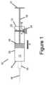
これより図1を参照して、近位端部12及び遠位端部14を有するシリンジ10を備える、第1の実施形態によるデバイスが提供される。近位端部12は、遠位端部14に対してシリンジ10の反対側の端部に置かれる。シリンジ10の遠位端部14は、オリフィスを有するハブ15を含んでもよく、このオリフィスから、遠位端部14に含まれている薬液11が排出され得る。ハブ15は、このオリフィス内に、又はこのオリフィスと流体連通したニードル(注射針)又はカニューレ16を、場合により含有してもよい。1, a device according to a first embodiment is provided that includes a
シリンジ10は、プランジャー18によって仕切られている内部空間を有するシリンジバレル20を備える。プランジャー18は、シリンジ10のバレル20に挿入されており、シリンジの遠位端部14から近位端部12の方向(矢印Aによって表示されている)に摺動するよう構成されている。プランジャー18を作動させるため、プランジャーロッド19は、プランジャー18に取り付けられた第1の端部を有することができ、ユーザーは、プランジャーロッド19の反対側にある第2の端部の親指パッド21に力をかけることによって、プランジャーロッド19を押し下げることができる。プランジャー18は、エラストマー材料から作製されることが好ましく、密封によって遠位端部14から近位端部12への薬液11の漏れを防止するよう、バレル20の内径よりもわずかに大きな外径を有する。The
薬剤充填済み注射器などのシリンジの近位端部12は一般に、外気中に開口している。しかし、図1に例示されているとおり、第1の実施形態によるデバイスは固定障壁22を含んでいてもよく、その結果、近位端部12は少なくとも一部が周囲の空気から遮断されている。固定障壁22は中央に開口部を含んでいてもよく、この開口部を通してプランジャーロッド19を摺動させると共に、プランジャーロッド19の外周面及びシリンジ10のバレル20の内周面の周囲にシール面を形成する。固定障壁22は、さまざまな材料から作製されてもよく、かつ中実壁、弾性ワッシャ、バッフル又はスクリーンの形態で設けられてもよく、好ましくは、周囲の外気からバレル20の近位端部12の内部空間を十分に遮断する。The
本デバイスは、2つの開口端部すなわちポートを有するセンサ24を更に備えており、これらを介して外側大気から空気をセンサ24へ引き込むことができる。薬物を投与する間にシリンジへ入る周囲空気の流量を検出するため、センサ24は、シリンジバレル20の近位端部12と流体連通した1つのポート、及び大気に開口したもう一方のポートを有するべきであり、これらの2つのポートは、好ましくは障壁22などの障壁により、空気の流れがセンサの両側にわたって圧力を低下させるのには十分である程度に仕切られている。例えば、構成の1つではセンサ24が、障壁22に隣接したシリンジ10の壁に取り付けられていてもよく、こうして、センサ24のポートの1つは、プランジャー18と障壁22との間のある点であって、シリンジ10の近位端部12内の内部空間と流体連通した上記の点に取り付けられている一方、センサ24のもう一方のポートは外部大気と流体連通している。プランジャー18が前進すると、周囲空気が(矢印Bにより表示されているとおり)センサ24を通してシリンジ10の近位端部12へ入り、検出可能な圧力低下を生じさせる。センサ24は、好ましくは、アンテナ及び十分な電源と連結されており、その結果、センサ24によって収集されたデータは無線で送信され得る。The device further includes a
センサの両端にわたる圧力低下は、検出可能となる程十分に大きくあるべきであるが、シリンジの操作を妨げ、又は使い勝手を損なうほど大きくあるべきではない。本明細書において開示されているさまざまな実施形態によるデバイスは、圧力低下により、空気の有限な流量がセンサを通過するように構成されるべきである。シリンジの近位端部へ引き込まれた空気の総量は、センサからの圧力の測定値を、データを格納して流量の経時的変化を計算し、シリンジの近位端部へ引き込まれた全量が積分され得る流量曲線を生成することができる制御装置に送信することによって求めることができる。シリンジは、一般に、プランジャーの両側に実質的に同じ幾何学形状を有する剛性容器であるので、この全量は、シリンジハブにおけるオリフィスからシリンジを出る薬液の量にほぼ等しい、又は少なくとも正比例するはずである。プランジャーの両側の掃引量は、プランジャーロッドが、シリンジバレルの内部空間の近位端部の範囲内の有限体積を占有することを除外すると実質的に等しい。しかし、内部空間を占めるプランジャーロッドの部分の寸法は、例えば、制御装置によって容易に計算又は推定することができる。The pressure drop across the sensor should be large enough to be detectable, but not so large that it interferes with the operation of the syringe or impairs ease of use. Devices according to various embodiments disclosed herein should be configured such that the pressure drop causes a finite flow rate of air to pass through the sensor. The total amount of air drawn into the proximal end of the syringe can be determined by sending pressure measurements from the sensor to a controller that can store the data, calculate the change in flow rate over time, and generate a flow rate curve over which the total amount drawn into the proximal end of the syringe can be integrated. Since syringes are generally rigid containers with substantially the same geometry on both sides of the plunger, this total amount should be approximately equal, or at least directly proportional, to the amount of drug fluid exiting the syringe from the orifice in the syringe hub. The amount of sweep on both sides of the plunger is substantially equal except that the plunger rod occupies a finite volume within the proximal end of the interior space of the syringe barrel. However, the dimensions of the portion of the plunger rod that occupies the interior space can be easily calculated or estimated, for example, by the controller.
先に明記したとおり、本明細書において開示されている実施形態は、プランジャーがシリンジバレル内で動くと、シリンジバレルの開口端部へ入る、少量ではあるが有限の流量の空気を利用する。本明細書に開示されているデバイスは、シリンジの近傍にセンサを好ましくは組み込んでおり、プランジャーが前方に動くことができるシリンジバレル内に、流体の流れに対する障壁を含む。一例として、障壁として使用されるフラットワッシャを使用して、センサの両側にわたる適度な圧力低下を生じさせることができる。その他に、それほど好ましくない実施形態では、注射器の近位端部への周囲空気の流れの抵抗が最小となる経路がセンサを介するよう流路に成形された壁又は一連のバッフルとして、圧力低下を生じさせる部分が実現されてもよい。このような実施形態では、壁又はバッフルによって占有された体積は、例えば、制御装置による計算に考慮されると思われる。以下に一層詳細に記載されている更に別の実施形態では、シリンジ全体がハウジングに囲まれていてもよい。このハウジングは、シリンジの近位端部と大気とを連結する流体経路、及び流体経路内に位置するセンサを有する。このハウジングは、障壁として働くよう構成されていてもよい。このような構成を、例えば自動注射器に使用すれば、シリンジへのいかなる特別な改変を必要とすることなく、シリンジ操作を監視することができるだろう。As noted above, the embodiments disclosed herein utilize a small but finite flow of air that enters the open end of the syringe barrel as the plunger moves within the syringe barrel. The devices disclosed herein preferably incorporate a sensor in the vicinity of the syringe and include a barrier to fluid flow within the syringe barrel through which the plunger can move forward. As an example, a flat washer used as the barrier can be used to create a moderate pressure drop across the sensor. In other, less preferred embodiments, the pressure drop may be realized as a wall or a series of baffles molded into the flow path to provide a least resistance path for ambient air to flow to the proximal end of the syringe through the sensor. In such embodiments, the volume occupied by the wall or baffles would be taken into account, for example, in calculations by the controller. In yet another embodiment, described in more detail below, the entire syringe may be enclosed in a housing. The housing has a fluid path connecting the proximal end of the syringe to the atmosphere and a sensor located within the fluid path. The housing may be configured to act as a barrier. Such a configuration, for example, could be used in an auto-injector to monitor syringe operation without requiring any special modifications to the syringe.
本明細書において開示されている実施形態によるデバイスには、シリンジへの機械連結部が実装されていてもよいが、それは、必要要件ではない。同様に、シリンジバレルへ引き込まれる周囲流体は、空気となる可能性が高いが、本明細書において開示されている実施形態は、プランジャーを前方に動かすようシリンジバレルの近位端に圧力をかけるのに液体のプールを利用することができるデバイスにも適用可能である。更に、デバイスが検出することができる量の範囲に制限はない。したがって、本デバイスは、さまざまなサイズのシリンジを備えることができる。最後に、シリンジへ入る周囲空気の有限量は、目的の使用、すなわち、治療剤のレジメンに対する患者のアドヒアランスを監視して記録することを、センサに首尾よく、かつ正確に支援可能にさせるのには十分な体積である。Although devices according to embodiments disclosed herein may be implemented with a mechanical connection to the syringe, this is not a requirement. Similarly, while the ambient fluid drawn into the syringe barrel will likely be air, the embodiments disclosed herein are also applicable to devices that can utilize a pool of liquid to apply pressure to the proximal end of the syringe barrel to move the plunger forward. Furthermore, there is no limit to the range of volumes that the device can detect. Thus, the device can include syringes of various sizes. Finally, the finite amount of ambient air entering the syringe is a sufficient volume to allow the sensor to successfully and accurately support its intended use, i.e., monitoring and recording a patient's adherence to a regimen of therapeutic agents.
上に列挙した態様に加え、本明細書において開示されているデバイスは、特に、モータを利用してプランジャーを前に動かすために一貫した一定の力をかける自動注射器又は類似のデバイスのために、シリンジ又はその操作に関する他の情報を検出することができる。このような追加情報を使用して、患者又は医療従事者に注意又は警告を提供することができる。例えば、使用中に観察される異常な流れに完全に基づいた薬物内の気泡及び/又は微粒子の存在を検出することが可能である。気泡はニードルを移動するときに流量を瞬間的に増加させやすい。一方、微粒子は流量を減少させる。In addition to the aspects listed above, the devices disclosed herein can detect other information regarding the syringe or its operation, particularly for auto-injectors or similar devices that utilize a motor to apply a consistent and constant force to move the plunger forward. Such additional information can be used to provide a notice or warning to the patient or medical personnel. For example, it is possible to detect the presence of air bubbles and/or particulates in the medication based entirely on abnormal flow observed during use. Air bubbles tend to momentarily increase the flow rate as the needle moves, whereas particulates decrease the flow rate.
小さなニードルオリフィスによって粘度の高い薬物に対して呈される高インピーダンスは、自動注射器のプランジャー速度を、粘度に依存する範囲に自然に制限する。したがって、別の例において、予想範囲外のプランジャー速度を検出することによって、薬物粘度の変化を監視することも可能である。例えば、温度が低くなるほど、薬物粘度が上昇する傾向がある。特定の薬物が使用前に冷蔵されることは珍しいことではないので、このような薬物を室温に到達させる前にそれらを使用する患者は、所望の範囲外となるおそれがある一層低いプランジャー速度を経験し得る。ニードルオリフィスサイズも、プランジャー速度に影響を及ぼす。したがって、ニードルが屈曲されるか、又は塞がると起こり得る、ニードルの幾何学的形状のいかなる変化も、予想範囲外のプランジャー速度を検出させることができる。The high impedance presented by a small needle orifice to a viscous drug naturally limits the plunger speed of an auto-injector to a range that is viscosity dependent. Thus, in another example, changes in drug viscosity can be monitored by detecting plunger speeds outside of the expected range. For example, lower temperatures tend to increase drug viscosity. Since it is not uncommon for certain drugs to be refrigerated prior to use, patients who use such drugs before they reach room temperature may experience lower plunger speeds that may be outside of the desired range. Needle orifice size also affects plunger speed. Thus, any changes in needle geometry, which may occur if the needle is bent or blocked, can cause plunger speeds outside of the expected range to be detected.
先に明記したとおり、本明細書において開示されている実施形態によるデバイスは、シリンジ直径の範囲の場合の排出流体の量を計算することが可能であり、シリンジ容量が増加するにつれて、測定された量の精度が低下しない。プランジャーの軸方向の変位を感知又は検出することによって、シリンジから排出された薬液の量を計算することを試みる場合、計算された量はシリンジの直径に依存する。例えば定型的な1mLシリンジは、プランジャーを35mm移動させるごとに概ね1mLの液体を排出し、すなわち28.5pL/mmで排液する。定型的な3mLシリンジは、プランジャーを40mm移動させるごとに概ね2.5mLを、すなわち62.5pL/mmで排液する。プランジャーの軸方向の変位の増分の小さな変化は検出が難しく、又は不正確であるので、シリンジの直径が大きくなるにつれて、計算された排出量の不確かさが増加し、すなわちその精度が低下する。本明細書において開示されている実施形態によるデバイスは、プランジャーの変位の検出に依らずに、周囲の空気の取り込み量から排出量を計算するので、シリンジの直径が増大しても、計算される排出量の精度が維持される。As previously noted, the devices according to the embodiments disclosed herein are capable of calculating the amount of fluid dispensed for a range of syringe diameters, and the accuracy of the measured amount does not decrease as the syringe volume increases. When attempting to calculate the amount of drug solution dispensed from a syringe by sensing or detecting the axial displacement of the plunger, the calculated amount depends on the diameter of the syringe. For example, a typical 1 mL syringe dispenses approximately 1 mL of liquid for every 35 mm of plunger movement, i.e., drains at 28.5 pL/mm. A typical 3 mL syringe dispenses approximately 2.5 mL for every 40 mm of plunger movement, i.e., drains at 62.5 pL/mm. Since small incremental changes in the axial displacement of the plunger are difficult or imprecise to detect, the uncertainty of the calculated amount of dispensed increases, i.e., its accuracy decreases, as the diameter of the syringe increases. The device according to the embodiment disclosed herein calculates the discharge volume from the amount of ambient air entrapped, rather than relying on detection of plunger displacement, so the accuracy of the calculated discharge volume is maintained even as the syringe diameter increases.
更に別の態様では、密封に欠陥があることによりシリンジバレルの近位端部に薬液の漏れを生じさせるプランジャーはまた、漏れた液体が、漏れがない場合に周囲空気によって充填されるはずの空間を占有するので、本明細書において開示されているデバイスを使用してやはり検出され得る。投与された医薬の量を決定するために、軸方向のプランジャーの変位に依存により、このような漏れは検出されず、それによって、患者にとって潜在的な有害な状況を作り出す。排出された量を決定するためにプランジャーの変位に依存する場合、漏れが仮に発生した場合でさえも、プランジャーがシリンジバレルの端部まで前方に動かされると、患者が医薬のすべてを投与したとみなされてしまうだろう。In yet another aspect, a plunger that has a defective seal causing a leak of medical fluid at the proximal end of the syringe barrel can also be detected using the devices disclosed herein, since the leaked fluid occupies space that would otherwise be filled by ambient air. Reliance on axial plunger displacement to determine the amount of medication administered would cause such a leak to go undetected, thereby creating a potentially harmful situation for the patient. If plunger displacement were relied upon to determine the amount expelled, the patient would be deemed to have administered all of the medication once the plunger was moved forward to the end of the syringe barrel, even if a leak did occur.
薬剤充填済み注射器が再使用可能である可能性は低い。既に記載した実施形態では、障壁は、シリンジバレルに組み込まれている。したがって、ユーザーは、薬液の投与後、デバイス全体を廃棄する可能性が高い。しかし、本明細書において開示されているさまざまな実施形態によるデバイスは、再使用可能となるよう構成されてもよい。例えば、図2、及び図3A~図3Eを参照すると、第2の実施形態によるデバイスが提供される。既に記載したデバイスと同様に、図2のデバイスは、シリンジバレル20、及びシリンジバレル20内で摺動するよう構成されているプランジャー18を含む。プランジャー18に付けられたプランジャーロッド19は、プランジャー18の変位を可能にする。プランジャーロッド19の反対側の端部は親指パッド21を含んでおり、その結果、プランジャーロッド19及びプランジャー18は、容易に前方に動かされ得る。既に記載した実施形態とは異なり、シリンジバレル20の近位端部12には障壁が設置されていない。代わりに、シリンジバレル20には、取り外して再利用することの可能な延長ハウジング28が、近位端部12に隣接するように取り付けられてもよい。延長ハウジング28には内部障壁22が設けられている。既に記載された障壁と同様、障壁22はシリンジバレル20の長軸とほぼ直交しており、中央に、プランジャーロッド19を通すことのできる隙間23が位置する。延長ハウジング28の壁にはセンサ24が取り付けられていてもよい。センサ24の一方のポートは障壁22の片側でハウジング28の内部空間と流体連通している一方、もう一方のポートは障壁22の反対側でその内部空間に流体連通している。プランジャー18が前方に動くと、周囲空気がセンサ24を通して近位端部12へ引き込まれる。It is unlikely that a pre-filled syringe is reusable. In the previously described embodiments, the barrier is integrated into the syringe barrel. Thus, the user is likely to discard the entire device after administration of the drug solution. However, the devices according to the various embodiments disclosed herein may be configured to be reusable. For example, with reference to FIG. 2 and FIGS. 3A-3E, a device according to a second embodiment is provided. As with the previously described devices, the device of FIG. 2 includes a
図3A~図3Eを参照すると、延長ハウジング28は、例えば、ヒンジ27と相互に取り付けられた2つの部品を備えてもよく、その結果、ハウジング28はクラムシェル構成と同様に開閉ができる。好ましくは、ヒンジ27に対してハウジング28の反対側は、留め具(図示せず)などの固定機構部を含んで、使用中、ハウジング28を閉鎖状態に維持する。延長ハウジング28を装備するために延長ハウジング28は開かれる(図3C)。ユーザーは、プランジャーロッド19が隙間23内に位置していること、及びシリンジバレル20の近位端部12における開口端部が障壁22の片側でハウジング28内に位置している(図3D)ことを確認し、その後、延長ハウジングが最終的に閉じられる(図3E)。延長ハウジング28の内径がシリンジバレル20の外径にほぼ等しいことにより、これら2つの構成要素間にしっかりとした締まりばめが確保されることが好ましい。その他に、Oリングなどのエラストマー製シールが、シリンジバレル20の外側表面と延長ハウジング28の内部表面との間に挿入されてもよい。一部の実施形態では、延長ハウジング28の外側表面には、プランジャーロッド19の作動を容易にするために、指フランジ(図示せず)が場合により設けられていてもよい。シリンジバレル20中の薬液が投与された後に、延長ハウジング28が、使用したシリンジを除去して廃棄するために開口され得る。その後、延長ハウジング28は、次に予定されている投与の前に、新しいシリンジに取り付けられ得る。実施形態が再使用可能なので、延長ハウジング28は、センサ24によって検出された情報を収集及び伝送するのに十分なエネルギーを供給することができる、再充電可能な電池などの電力貯蔵手段(図示せず)を更に備えてもよい。3A-3E, the
代替的な実施形態では、延長ハウジングは、ヒンジを含まない単一部品として提供されてもよい。延長ハウジングを取り付ける、及び取り外すために、プランジャーロッドは、例えば、プランジャーからプランジャーロッドの端部を解除することによって、プランジャーから取り外し可能となり得る。このような構成では、プランジャーロッドと延長ハウジングの両方が再使用可能である。医薬を含有する新しい薬剤充填済み注射器は、プランジャーロッドのないプランジャーを含んでもよく、その結果、再使用可能なプランジャーロッドは、新しいプランジャー、及び新しいシリンジバレルの近位端部に取り付けられた延長ハウジングに装着され得る。In alternative embodiments, the extension housing may be provided as a single piece that does not include a hinge. To attach and remove the extension housing, the plunger rod may be removable from the plunger, for example, by releasing the end of the plunger rod from the plunger. In such a configuration, both the plunger rod and the extension housing are reusable. A new pre-filled syringe containing a medicament may include a plunger without the plunger rod, such that a reusable plunger rod can be attached to a new plunger and the extension housing attached to the proximal end of a new syringe barrel.
更に別の実施形態では、放出された流体の量を決定するためのセンサが、プランジャーロッド内に完全に組み込まれてもよい。例えば図4を参照すると、シリンジバレル20、及びシリンジバレル20内で摺動するよう構成されているプランジャー18を含む点で、既に記載した実施形態に類似したデバイスが提供される。プランジャー18に取り付けられたプランジャーロッド19は、プランジャー18の変位を可能にする。プランジャーロッド19の反対側の端部は親指パッド21を含んでおり、その結果、プランジャーロッド19及びプランジャー18は、容易に前方に動かされ得る。既に記載した障壁に類似した固定障壁22は、シリンジバレル20の近位端部12内に位置しており、プランジャーロッド19が延在する中央部隙間を含む。既に記載した実施形態とは異なり、プランジャーロッド19は、意図的に中空であり、プランジャー18に取り付けられた端部の近位にある開口部17であって、シリンジバレル20の近位端部12の内部空間と流体連通している開口部17を含む。プランジャーロッド19の対向端部は、親指パッド21内に収容された、ダイヤフラムセンサなどのセンサ24のポートの1つに取り付けられており、こうして、センサ24は、中空プランジャーロッド19と流体連通している。センサ24の第2のポートは、周囲大気に開口している。障壁22は、プランジャー18が前方に動くときにシリンジバレル20の近位端部12へ入る周囲空気の抵抗が最小になる経路が、流量センサ24、プランジャーロッド19を通り、最終的に開口部17から出るように構成されており、それにより、検出され得る流量センサ24に圧力低下を作り出す。この構成により、電気的構成要素(例えば、センサ、アンテナ、電力貯蔵など)の大部分を親指パッド21内に収容することが可能となる。いくつかの用途に関すると、薬液を投与した後に、プランジャーロッドをプランジャーから取り外して空の注射器を廃棄し、プランジャーロッドを新しいシリンジのプランジャーに再取り付けすることにより、プランジャーロッドを再利用することが許容され得る。In yet another embodiment, a sensor for determining the amount of fluid dispensed may be fully integrated into the plunger rod. For example, referring to FIG. 4, a device similar to the previously described embodiment is provided in that it includes a
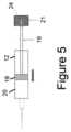
一部の実施形態では、プランジャーの近位のプランジャーロッドに開口部を組み込むことは必要ではない。例えば、図5に例示されている実施形態は、既に記載した実施形態に類似する中空プランジャーロッド19を含む。しかし、中空プランジャーロッド19の一方の端部は、エラストマー製プランジャー19によって閉鎖されている。センサ24は、中空プランジャーロッドの一方の端部に取り付けられたポートを含む一方、もう一方のポートは大気に開口している。しかし、空気は、プランジャー18が前に動くと、センサ24を流れて通過することはできない。代わりに、プランジャー18を前方に動かすと、プランジャー18は偏向し、プランジャーロッド19内の密封された空間内で空気を圧縮する。したがって、差圧の変化は、中空プランジャーロッド19内の圧力と基準圧である周囲大気圧との比較により、センサ24によって検出される。センサ24の感度を周囲大気圧の変動に制限するために、小さなピンホールが、局所大気圧へとゆっくりと平衡となることが可能なプランジャーロッド19に設けられていてもよい。In some embodiments, it is not necessary to incorporate an opening in the plunger rod proximal to the plunger. For example, the embodiment illustrated in FIG. 5 includes a
さまざまな圧力センサが、さまざまな圧力操作範囲を提示し、本明細書に記載されている実施形態によるデバイスに使用されるシリンジ用に適切に選択され得る。例えば、ダイヤフラム型の差圧センサの範囲は、±500Paとすることができる一方、NXP Semiconductors N.V.(Eindhoven、オランダ)の又はBosch Sensortec GmbH(Reutlingen、ドイツ)によって製造されているものなどの、気圧センサは、数万パスカルの範囲にわたり作動することができる。気圧センサは、一層小さな電池サイズ及び容量しか必要としない低電力レベルで作動するので、それらもまた好ましいものとなり得る。Various pressure sensors offer different pressure operating ranges and may be appropriately selected for use with a syringe used in a device according to the embodiments described herein. For example, a diaphragm-type differential pressure sensor may have a range of ±500 Pa, while air pressure sensors, such as those manufactured by NXP Semiconductors N.V. (Eindhoven, The Netherlands) or Bosch Sensortec GmbH (Reutlingen, Germany), can operate over a range of tens of thousands of Pascals. Air pressure sensors may also be preferred because they operate at lower power levels requiring smaller battery size and capacity.
先に明記したとおり、デバイスのある部材が、センサに圧力低下を生じさせるシリンジバレルの近位端部への周囲流れに対する好適な障壁として機能できる場合、シリンジバレル内に特定の障壁を組み入れる必要はない。図6をこれより参照すると、例えば、自動注射器、ペン型注射器又は装着可能な注射デバイスの形態で提供されてもよい、別の実施形態によるデバイスが例示される。デバイスは、遠位端部14に対してシリンジ10の反対側の端部に位置する近位端部12を有するシリンジバレル20を備えている点で、既に記載した実施形態に類似している。遠位端部14はまた、任意選択のニードル16を備えるオリフィスを有するハブ15を含んでもよく、このオリフィスから、遠位端部14へ入っている薬液11が排出され得る。一部の実施形態では、シリンジは、例えば、ハウジング内に装着されている両端カニューレ及び交換可能カートリッジを備えてもよい。As previously noted, it is not necessary to incorporate a specific barrier into the syringe barrel if some component of the device can act as a suitable barrier to ambient flow to the proximal end of the syringe barrel that would cause a pressure drop across the sensor. Referring now to FIG. 6, another embodiment of the device is illustrated, which may be provided in the form of, for example, an autoinjector, pen injector, or wearable injection device. The device is similar to the previously described embodiment in that it comprises a
やはり、シリンジバレル20は、プランジャーロッド19により作動されるエラストマー製プランジャー18によって隔離されている内部空間を有する。しかし、これまでの実施形態とは異なり、プランジャーロッド19の近位端は、プランジャー18を前方に動かすため、例えばモータ23に機械的に取り付けられてもよい。Again, the
図6のデバイスは、近位端部12が固定障壁を含まない点でも異なる。代わりに、このデバイスは、ハウジングドア26を有するハウジング25を含む。ハウジングドア26は、ユーザーが新品の薬剤充填済み注射器、又は医薬が充填されたカートリッジを挿入できるように、ハウジング25の内側へのアクセスを可能にする。既に記載したとおり、センサ24は、ハウジング内に埋包されているか、又は装着されている。センサ24は、2つのポートを含み、これらのポートから、外側大気からの空気が、センサ24を通過して流れることができる(矢印Bで表示されているとおり)。したがって、センサ24は、シリンジバレル20の近位端部12と流体連通しているポートを1つ有するべきであり、もう一方のポートは、ハウジング25の外側の大気に対して開口している。そうでない場合、センサ24は、ハウジング25内のどこかに位置することができる。ハウジング25及びハウジングドア26は、ハウジングドア26の閉鎖時に、プランジャー18を前方に動かすと、近位端部12へ入る周囲空気に対して最小抵抗となる経路がセンサ24を通過するように好ましくは構成されており、それにより、センサに検出可能な圧力低下を作り出す。既に記載した再使用可能な実施形態と同様に、本デバイスは、センサ24がデータを収集して伝送することができるほど十分ないくつかの電力貯蔵手段を含むことが好ましい。
[実施例] The device of FIG. 6 also differs in that the
[Example]
本明細書において開示されている実施形態の態様は、以下の実施例を考慮すると、更に理解され、これらの実施例は、ある特定の実施形態を例示することが意図されているが、その範囲を限定することを意図するものではない。Aspects of the embodiments disclosed herein will be further understood in view of the following examples, which are intended to illustrate certain embodiments but are not intended to limit the scope thereof.
水道水が充填された1mLのシリンジを使用して、図7の写真に明示されているとおりの装置に類似したシステムを用意した。1mLシリンジの開口端を、障壁として働くハウジングに取り付けた。シリンジ及びそれに接続されたハウジングを基板上に実装し、差圧を受けるように接続した。すなわち、センサのポートの一方を、ハウジングを通してシリンジの開口端に接続し、他方を大気中に開口させた。センサを、別の基板に位置するマイクロ制御装置に接続し、これによって、マイクロ制御装置に関連する特注のファームウェア又はPCのいずれかを使用してセンサの測定値を操作し、記録することを可能にした。プランジャーを1回押し込むとシリンジ内の1mLの水が排出され、センサによって測定された圧力低下の経時的変化を、汎用非同期送受信機(universal asynchronous receiver-transmitter:UART)を使用して記録した。これにより、センサのデータをPCに収集することができた。A system similar to the device as shown in the photograph of Figure 7 was prepared using a 1 mL syringe filled with tap water. The open end of the 1 mL syringe was attached to a housing that acted as a barrier. The syringe and its connected housing were mounted on a board and connected to receive a differential pressure; one port of the sensor was connected to the open end of the syringe through the housing and the other was open to the atmosphere. The sensor was connected to a microcontroller located on a separate board, which allowed the sensor measurements to be manipulated and recorded using either custom firmware associated with the microcontroller or a PC. A single depression of the plunger expelled 1 mL of water in the syringe, and the pressure drop measured by the sensor over time was recorded using a universal asynchronous receiver-transmitter (UART). This allowed the sensor data to be collected on a PC.
センサによって測定された圧力低下から計算された流量の経時的変化が、図8のグラフに表されている。グラフにプロットされた流量の経時的変化が積分されることにより、対応する全排出量の経時的変化が得られた(図8のグラフにはこれも表されている)。これらの結果は、センサがシリンジからの1mLの液体の排出を正確に監視して記録できたことを明示している。The change in flow rate over time, calculated from the pressure drop measured by the sensor, is shown in the graph of Figure 8. The plotted change in flow rate over time was integrated to obtain the corresponding change in total discharge over time (also shown in the graph of Figure 8). These results demonstrate that the sensor was able to accurately monitor and record the discharge of 1 mL of liquid from the syringe.
当業者は、その広範な発明概念から逸脱することなく、上記の実施形態に変更を行うことができることが理解されるであろう。したがって、本発明は、開示されている特定の実施形態に限定されるものではないが、添付の特許請求の範囲によって規定される本発明の趣旨及び範囲内での変更を網羅することが意図されることが理解される。Those skilled in the art will appreciate that changes could be made to the above-described embodiments without departing from the broad inventive concept thereof. It is understood, therefore, that the invention is not limited to the particular embodiments disclosed, but is intended to cover modifications within the spirit and scope of the invention as defined by the appended claims.
Claims (18)
Translated fromJapanese前記シリンジバレルの内部に前記シリンジバレルの近位端部から前記シリンジバレルの遠位端部へ向かって摺動するように設置されており、前記シリンジバレルの近位端部と前記シリンジバレルの遠位端部との間を密封するように構成されているプランジャーと、
前記シリンジバレルの近位端部の内部に設置されている障壁と、
前記障壁によって分離されている第1のポート及び第2のポートを有するセンサと
を備えるデバイスであって、
前記プランジャーと前記障壁との間には、前記センサの第1のポートと流体連通している第1の内部空間が形成されており、
前記シリンジバレルの外部の流体源と前記障壁との間には、前記センサの第2のポートと流体連通している第2の内部空間が形成されており、前記第2の内部空間が前記流体源に対して開口しており、
前記障壁が前記第1の内部空間と前記第2の内部空間との間を流体連通させず、
前記センサが、前記流体源から前記第2の内部空間を通して前記センサの第2のポートへ流れ込み、前記センサの中を通ることにより前記障壁を迂回し、前記センサの第1のポートから前記第1の内部空間へ流れ出る流量を検出するように構成されている
ことを特徴とするデバイス。 A syringe barrel;
a plunger disposed within the syringe barrel so as to slide from a proximal end of the syringe barrel toward a distal end of the syringe barrel and configured to seal between the proximal end of the syringe barrel and the distal end of the syringe barrel;
a barrier disposed within the proximal end of the syringe barrel;
a sensor having a first port and a second port separated by the barrier,
a first interior space defined between the plunger and the barrier in fluid communication with a first port of the sensor;
a second interior space is formed between a fluid source external to the syringe barrel and the barrier, the second interior space being in fluid communication with a second port of the sensor, the second interior space being open to the fluid source;
the barrier does not provide fluid communication between the first interior space and the second interior space;
The device, characterized in that the sensor is configured to detect a flow rate of a fluid from the fluid source through the second interior space into the second port of the sensor, bypassing the barrier by passing through the sensor, and flowing out the first port of the sensor into the first interior space.
を更に備え、
前記延長ハウジングが前記障壁を含み、前記障壁が固定されており、前記第1のポートが前記障壁と前記プランジャーとの間のある点において前記第1の内部空間に流体連通している、
請求項1に記載のデバイス。 an extension housing attached to a proximal end of the syringe barrel;
the extension housing includes the barrier, the barrier is fixed, and the first port is in fluid communication with the first interior space at a point between the barrier and the plunger;
The device of claim 1 .
を更に備え、
前記障壁は、
内側に前記プランジャーロッドが通過していると共に、前記プランジャーロッドの外周面のまわりがシールされている開口部
を含む、
請求項1に記載のデバイス。 a plunger rod attached to the plunger,
The barrier is
an opening through which the plunger rod passes and which is sealed around an outer periphery of the plunger rod;
The device of claim 1 .
前記シリンジバレルの内部にあるプランジャーであって、前記シリンジバレル内で前記近位端部から前記遠位端部へ向かって摺動するよう、及び前記近位端部と前記遠位端部との間を密封するよう構成されている前記プランジャーと、
第1及び第2のポートを有するセンサであって、前記第2のポートが前記シリンジバレルの外部の流体源と流体連通している前記センサと、
前記プランジャーによって閉鎖されている第1の端部、前記第1のポートと流体連通している第2の端部、及び、前記障壁と前記プランジャーとの間の空間と流体連通している開口部を有する中空プランジャーロッドと
を備えるデバイス。 a syringe barrel defining an interior space between a proximal end and a distal end, the proximal end including a barrier sealing at least a portion of the proximal end;
a plunger within the syringe barrel, the plunger configured to slide within the syringe barrel from the proximal end to the distal end and to form a seal between the proximal end and the distal end;
a sensor having first and second ports, the second port in fluid communication with a fluid source external to the syringe barrel;
A device comprising: a hollow plunger rod having a first end closed by the plunger, a second end in fluid communication with the first port, and an opening in fluid communication with a space between the barrier and the plunger.
Applications Claiming Priority (3)
| Application Number | Priority Date | Filing Date | Title |
|---|---|---|---|
| US201962869139P | 2019-07-01 | 2019-07-01 | |
| US62/869,139 | 2019-07-01 | ||
| PCT/US2020/040315WO2021003164A1 (en) | 2019-07-01 | 2020-06-30 | System and method for measuring fluid flow from a syringe |
Publications (2)
| Publication Number | Publication Date |
|---|---|
| JP2022539159A JP2022539159A (en) | 2022-09-07 |
| JP7500622B2true JP7500622B2 (en) | 2024-06-17 |
Family
ID=71833447
Family Applications (1)
| Application Number | Title | Priority Date | Filing Date |
|---|---|---|---|
| JP2021577447AActiveJP7500622B2 (en) | 2019-07-01 | 2020-06-30 | System for measuring fluid flow rate from a syringe - Patents.com |
Country Status (5)
| Country | Link |
|---|---|
| US (1) | US12013267B2 (en) |
| EP (1) | EP3993850A1 (en) |
| JP (1) | JP7500622B2 (en) |
| CN (1) | CN114096293B (en) |
| WO (1) | WO2021003164A1 (en) |
Families Citing this family (1)
| Publication number | Priority date | Publication date | Assignee | Title |
|---|---|---|---|---|
| CN119868724B (en)* | 2024-12-25 | 2025-09-19 | 杭州市职业病防治院 | Subcutaneous medicine filling material injection device and control system |
Citations (1)
| Publication number | Priority date | Publication date | Assignee | Title |
|---|---|---|---|---|
| WO2019122027A1 (en) | 2017-12-20 | 2019-06-27 | Sanofi | Pressure sensor for injection devices |
Family Cites Families (22)
| Publication number | Priority date | Publication date | Assignee | Title |
|---|---|---|---|---|
| US7449008B2 (en)* | 1998-04-10 | 2008-11-11 | Milestone Scientific, Inc. | Drug infusion device with tissue identification using pressure sensing |
| US6139523A (en)* | 1999-02-01 | 2000-10-31 | Merit Medical Systems, Inc. | Isolation system for pressure gauges for permitting repeated use without sterilization |
| US20010018575A1 (en)* | 1999-10-19 | 2001-08-30 | Lyza Henry Walter | Injector syringe |
| US7727195B2 (en)* | 2004-07-01 | 2010-06-01 | West Pharmaceutical Services, Inc. | Syringe device having venting system |
| US20070264130A1 (en)* | 2006-01-27 | 2007-11-15 | Phluid, Inc. | Infusion Pumps and Methods for Use |
| CN102716532A (en)* | 2008-01-15 | 2012-10-10 | 西部制药服务公司 | Collet mechanism and method of molding cannula to a syringe barrel |
| US20100076370A1 (en)* | 2008-09-23 | 2010-03-25 | Infusion Advancements, LLC. | Apparatus and methods for purging catheter systems |
| US9174007B2 (en)* | 2010-03-15 | 2015-11-03 | Becton, Dickinson And Company | Medical device including an air evacuation system |
| US8172794B2 (en)* | 2010-03-15 | 2012-05-08 | Becton, Dickinson And Company | Medical device including an air evacuation system |
| US9289562B2 (en)* | 2011-04-18 | 2016-03-22 | THORNE CONSULTING and INTELETUAL PROPERTY, LLC | Pressure actuated valve for multi-chamber syringe applications |
| US9022995B2 (en)* | 2011-08-01 | 2015-05-05 | Synchrojet Llc | Stopper/plunger for carpules of syringe-carpule assembly |
| CN103874522B (en)* | 2011-10-11 | 2016-02-03 | 呼吸医疗技术有限公司 | Pressure regulates syringe and method thereof |
| GB201210082D0 (en)* | 2012-06-07 | 2012-07-25 | Consort Medical Plc | Improved syringe |
| BR112015010607A2 (en)* | 2012-11-09 | 2017-12-05 | Iinjec Tech Inc | fluid delivery injector, retractable needle assembly, and method for injecting at least one dose of a transcutaneously fluid medication into the body. |
| US9623191B2 (en)* | 2013-03-01 | 2017-04-18 | Bayer Healthcare Llc | Information sensing syringe |
| US10046144B2 (en)* | 2013-08-03 | 2018-08-14 | Merit Medical Systems, Inc. | Methods of resetting inflation devices |
| GB2519596B (en)* | 2013-10-28 | 2016-05-18 | Consort Medical Plc | Medicament Delivery device |
| US9415176B1 (en)* | 2015-01-22 | 2016-08-16 | West Pharmaceutical Services, Inc. | Autoinjector having an end-of-dose visual indicator |
| IL239366B (en)* | 2015-06-11 | 2018-07-31 | Kriheli Marino | Components of a fluid transfer apparatus |
| JP2018527095A (en)* | 2015-09-11 | 2018-09-20 | ウエスト ファーマスーティカル サービシーズ インコーポレイテッド | MEDICAL ADMINISTRATION BARREL WITH GROOVE AND METHOD OF SEALING THE SAME |
| CA3026708A1 (en)* | 2016-05-24 | 2017-11-30 | Unl Holdings Llc | Accurate dose control mechanisms and drug delivery syringes |
| US11246984B2 (en)* | 2016-11-01 | 2022-02-15 | Sanofi-Aventis Deutschland Gmbh | Volume measuring arrangement |
- 2020
- 2020-06-30JPJP2021577447Apatent/JP7500622B2/enactiveActive
- 2020-06-30USUS17/622,195patent/US12013267B2/enactiveActive
- 2020-06-30EPEP20746787.9Apatent/EP3993850A1/enactivePending
- 2020-06-30CNCN202080050309.5Apatent/CN114096293B/enactiveActive
- 2020-06-30WOPCT/US2020/040315patent/WO2021003164A1/ennot_activeCeased
Patent Citations (1)
| Publication number | Priority date | Publication date | Assignee | Title |
|---|---|---|---|---|
| WO2019122027A1 (en) | 2017-12-20 | 2019-06-27 | Sanofi | Pressure sensor for injection devices |
Also Published As
| Publication number | Publication date |
|---|---|
| CN114096293B (en) | 2024-08-09 |
| WO2021003164A1 (en) | 2021-01-07 |
| US20220412783A1 (en) | 2022-12-29 |
| EP3993850A1 (en) | 2022-05-11 |
| CN114096293A (en) | 2022-02-25 |
| JP2022539159A (en) | 2022-09-07 |
| US12013267B2 (en) | 2024-06-18 |
Similar Documents
| Publication | Publication Date | Title |
|---|---|---|
| US9962486B2 (en) | System and method for detecting occlusions in an infusion pump | |
| US9814833B2 (en) | Pressure based refill status monitor for implantable pumps | |
| ES2799305T3 (en) | Smart adapter for infusion devices | |
| CN105848694B (en) | Fluid Control Systems and Disposable Components | |
| JP7526558B2 (en) | High-precision syringe with removable pump unit | |
| EP2854895A1 (en) | Infusion pump system with cartridge having pressure venting and pressure feedback | |
| US20250207964A1 (en) | Priming Valve to Induce Appropriate Pressure and Flow Profile and Improve Sensor Readiness | |
| CN111132713A (en) | Cartridge system for a drug delivery device | |
| JP2024508992A (en) | drug delivery device | |
| JP7500622B2 (en) | System for measuring fluid flow rate from a syringe - Patents.com | |
| US20220323672A1 (en) | System and device for dispensing a product | |
| JP5728632B2 (en) | Method for calibrating occlusion pressure in medical liquid pump and medical liquid pump | |
| JP7703602B2 (en) | Drug Delivery Devices | |
| JP2024511340A (en) | drug delivery device | |
| CN111683706A (en) | Syringe plunger stoppers for high dose precision drug delivery | |
| JP2024534106A (en) | Systems and methods for collecting infusion information |
Legal Events
| Date | Code | Title | Description |
|---|---|---|---|
| A521 | Request for written amendment filed | Free format text:JAPANESE INTERMEDIATE CODE: A523 Effective date:20220303 | |
| A621 | Written request for application examination | Free format text:JAPANESE INTERMEDIATE CODE: A621 Effective date:20220303 | |
| A977 | Report on retrieval | Free format text:JAPANESE INTERMEDIATE CODE: A971007 Effective date:20230117 | |
| A131 | Notification of reasons for refusal | Free format text:JAPANESE INTERMEDIATE CODE: A131 Effective date:20230201 | |
| A521 | Request for written amendment filed | Free format text:JAPANESE INTERMEDIATE CODE: A523 Effective date:20230420 | |
| A131 | Notification of reasons for refusal | Free format text:JAPANESE INTERMEDIATE CODE: A131 Effective date:20230808 | |
| A521 | Request for written amendment filed | Free format text:JAPANESE INTERMEDIATE CODE: A523 Effective date:20231107 | |
| A131 | Notification of reasons for refusal | Free format text:JAPANESE INTERMEDIATE CODE: A131 Effective date:20240131 | |
| A521 | Request for written amendment filed | Free format text:JAPANESE INTERMEDIATE CODE: A523 Effective date:20240422 | |
| TRDD | Decision of grant or rejection written | ||
| A01 | Written decision to grant a patent or to grant a registration (utility model) | Free format text:JAPANESE INTERMEDIATE CODE: A01 Effective date:20240522 | |
| A61 | First payment of annual fees (during grant procedure) | Free format text:JAPANESE INTERMEDIATE CODE: A61 Effective date:20240605 | |
| R150 | Certificate of patent or registration of utility model | Ref document number:7500622 Country of ref document:JP Free format text:JAPANESE INTERMEDIATE CODE: R150 |