JP7499357B2 - Compression molding machine and compression molding method - Google Patents
Compression molding machine and compression molding methodDownload PDFInfo
- Publication number
- JP7499357B2 JP7499357B2JP2022571262AJP2022571262AJP7499357B2JP 7499357 B2JP7499357 B2JP 7499357B2JP 2022571262 AJP2022571262 AJP 2022571262AJP 2022571262 AJP2022571262 AJP 2022571262AJP 7499357 B2JP7499357 B2JP 7499357B2
- Authority
- JP
- Japan
- Prior art keywords
- rod
- inspection
- charge
- inspection device
- extrusion
- Prior art date
- Legal status (The legal status is an assumption and is not a legal conclusion. Google has not performed a legal analysis and makes no representation as to the accuracy of the status listed.)
- Active
Links
- 238000000034methodMethods0.000titleclaimsdescription37
- 238000000748compression mouldingMethods0.000titleclaimsdescription27
- 239000000463materialSubstances0.000claimsdescription229
- 238000007689inspectionMethods0.000claimsdescription186
- 238000001125extrusionMethods0.000claimsdescription103
- 239000000203mixtureSubstances0.000claimsdescription21
- 238000000465mouldingMethods0.000claimsdescription21
- 235000011837pastiesNutrition0.000claimsdescription21
- 239000000126substanceSubstances0.000claimsdescription9
- 238000010521absorption reactionMethods0.000claimsdescription6
- 238000004519manufacturing processMethods0.000claimsdescription4
- 238000011144upstream manufacturingMethods0.000claimsdescription4
- 230000000704physical effectEffects0.000claimsdescription3
- 239000002861polymer materialSubstances0.000claimsdescription2
- 230000005484gravityEffects0.000description10
- 238000002347injectionMethods0.000description9
- 239000007924injectionSubstances0.000description9
- 239000004033plasticSubstances0.000description6
- 229920003023plasticPolymers0.000description6
- 230000005855radiationEffects0.000description5
- QVGXLLKOCUKJST-UHFFFAOYSA-Natomic oxygenChemical compound[O]QVGXLLKOCUKJST-UHFFFAOYSA-N0.000description4
- 229910052760oxygenInorganic materials0.000description4
- 239000001301oxygenSubstances0.000description4
- 229920000642polymerPolymers0.000description4
- 230000004888barrier functionEffects0.000description3
- 238000011161developmentMethods0.000description3
- 239000012467final productSubstances0.000description3
- 230000008569processEffects0.000description3
- 239000007787solidSubstances0.000description3
- 229920000219Ethylene vinyl alcoholPolymers0.000description2
- 230000009471actionEffects0.000description2
- 239000011324beadSubstances0.000description2
- 230000008901benefitEffects0.000description2
- 230000002950deficientEffects0.000description2
- 238000013461designMethods0.000description2
- 238000007599dischargingMethods0.000description2
- UFRKOOWSQGXVKV-UHFFFAOYSA-Nethene;ethenolChemical compoundC=C.OC=CUFRKOOWSQGXVKV-UHFFFAOYSA-N0.000description2
- 239000004715ethylene vinyl alcoholSubstances0.000description2
- 238000011156evaluationMethods0.000description2
- 239000000047productSubstances0.000description2
- 230000032258transportEffects0.000description2
- XLYOFNOQVPJJNP-UHFFFAOYSA-NwaterSubstancesOXLYOFNOQVPJJNP-UHFFFAOYSA-N0.000description2
- 238000004458analytical methodMethods0.000description1
- 239000002775capsuleSubstances0.000description1
- 238000004891communicationMethods0.000description1
- 230000005670electromagnetic radiationEffects0.000description1
- 238000005516engineering processMethods0.000description1
- 235000013305foodNutrition0.000description1
- 239000000243solutionSubstances0.000description1
- 239000012780transparent materialSubstances0.000description1
Images


Classifications
- B—PERFORMING OPERATIONS; TRANSPORTING
- B29—WORKING OF PLASTICS; WORKING OF SUBSTANCES IN A PLASTIC STATE IN GENERAL
- B29C—SHAPING OR JOINING OF PLASTICS; SHAPING OF MATERIAL IN A PLASTIC STATE, NOT OTHERWISE PROVIDED FOR; AFTER-TREATMENT OF THE SHAPED PRODUCTS, e.g. REPAIRING
- B29C43/00—Compression moulding, i.e. applying external pressure to flow the moulding material; Apparatus therefor
- B29C43/32—Component parts, details or accessories; Auxiliary operations
- B29C43/58—Measuring, controlling or regulating
- B—PERFORMING OPERATIONS; TRANSPORTING
- B29—WORKING OF PLASTICS; WORKING OF SUBSTANCES IN A PLASTIC STATE IN GENERAL
- B29C—SHAPING OR JOINING OF PLASTICS; SHAPING OF MATERIAL IN A PLASTIC STATE, NOT OTHERWISE PROVIDED FOR; AFTER-TREATMENT OF THE SHAPED PRODUCTS, e.g. REPAIRING
- B29C43/00—Compression moulding, i.e. applying external pressure to flow the moulding material; Apparatus therefor
- B29C43/02—Compression moulding, i.e. applying external pressure to flow the moulding material; Apparatus therefor of articles of definite length, i.e. discrete articles
- B—PERFORMING OPERATIONS; TRANSPORTING
- B29—WORKING OF PLASTICS; WORKING OF SUBSTANCES IN A PLASTIC STATE IN GENERAL
- B29C—SHAPING OR JOINING OF PLASTICS; SHAPING OF MATERIAL IN A PLASTIC STATE, NOT OTHERWISE PROVIDED FOR; AFTER-TREATMENT OF THE SHAPED PRODUCTS, e.g. REPAIRING
- B29C48/00—Extrusion moulding, i.e. expressing the moulding material through a die or nozzle which imparts the desired form; Apparatus therefor
- B29C48/001—Combinations of extrusion moulding with other shaping operations
- B29C48/0011—Combinations of extrusion moulding with other shaping operations combined with compression moulding
- B—PERFORMING OPERATIONS; TRANSPORTING
- B29—WORKING OF PLASTICS; WORKING OF SUBSTANCES IN A PLASTIC STATE IN GENERAL
- B29C—SHAPING OR JOINING OF PLASTICS; SHAPING OF MATERIAL IN A PLASTIC STATE, NOT OTHERWISE PROVIDED FOR; AFTER-TREATMENT OF THE SHAPED PRODUCTS, e.g. REPAIRING
- B29C48/00—Extrusion moulding, i.e. expressing the moulding material through a die or nozzle which imparts the desired form; Apparatus therefor
- B29C48/25—Component parts, details or accessories; Auxiliary operations
- B29C48/92—Measuring, controlling or regulating
- G—PHYSICS
- G01—MEASURING; TESTING
- G01N—INVESTIGATING OR ANALYSING MATERIALS BY DETERMINING THEIR CHEMICAL OR PHYSICAL PROPERTIES
- G01N23/00—Investigating or analysing materials by the use of wave or particle radiation, e.g. X-rays or neutrons, not covered by groups G01N3/00 – G01N17/00, G01N21/00 or G01N22/00
- G01N23/02—Investigating or analysing materials by the use of wave or particle radiation, e.g. X-rays or neutrons, not covered by groups G01N3/00 – G01N17/00, G01N21/00 or G01N22/00 by transmitting the radiation through the material
- G01N23/06—Investigating or analysing materials by the use of wave or particle radiation, e.g. X-rays or neutrons, not covered by groups G01N3/00 – G01N17/00, G01N21/00 or G01N22/00 by transmitting the radiation through the material and measuring the absorption
- G01N23/083—Investigating or analysing materials by the use of wave or particle radiation, e.g. X-rays or neutrons, not covered by groups G01N3/00 – G01N17/00, G01N21/00 or G01N22/00 by transmitting the radiation through the material and measuring the absorption the radiation being X-rays
- G—PHYSICS
- G01—MEASURING; TESTING
- G01N—INVESTIGATING OR ANALYSING MATERIALS BY DETERMINING THEIR CHEMICAL OR PHYSICAL PROPERTIES
- G01N23/00—Investigating or analysing materials by the use of wave or particle radiation, e.g. X-rays or neutrons, not covered by groups G01N3/00 – G01N17/00, G01N21/00 or G01N22/00
- G01N23/02—Investigating or analysing materials by the use of wave or particle radiation, e.g. X-rays or neutrons, not covered by groups G01N3/00 – G01N17/00, G01N21/00 or G01N22/00 by transmitting the radiation through the material
- G01N23/06—Investigating or analysing materials by the use of wave or particle radiation, e.g. X-rays or neutrons, not covered by groups G01N3/00 – G01N17/00, G01N21/00 or G01N22/00 by transmitting the radiation through the material and measuring the absorption
- G01N23/18—Investigating the presence of flaws defects or foreign matter
- B—PERFORMING OPERATIONS; TRANSPORTING
- B29—WORKING OF PLASTICS; WORKING OF SUBSTANCES IN A PLASTIC STATE IN GENERAL
- B29C—SHAPING OR JOINING OF PLASTICS; SHAPING OF MATERIAL IN A PLASTIC STATE, NOT OTHERWISE PROVIDED FOR; AFTER-TREATMENT OF THE SHAPED PRODUCTS, e.g. REPAIRING
- B29C43/00—Compression moulding, i.e. applying external pressure to flow the moulding material; Apparatus therefor
- B29C43/32—Component parts, details or accessories; Auxiliary operations
- B29C43/36—Moulds for making articles of definite length, i.e. discrete articles
- B29C2043/3676—Moulds for making articles of definite length, i.e. discrete articles moulds mounted on rotating supporting constuctions
- B29C2043/3689—Moulds for making articles of definite length, i.e. discrete articles moulds mounted on rotating supporting constuctions on a support table, e.g. flat disk-like tables having moulds on the periphery
- B—PERFORMING OPERATIONS; TRANSPORTING
- B29—WORKING OF PLASTICS; WORKING OF SUBSTANCES IN A PLASTIC STATE IN GENERAL
- B29C—SHAPING OR JOINING OF PLASTICS; SHAPING OF MATERIAL IN A PLASTIC STATE, NOT OTHERWISE PROVIDED FOR; AFTER-TREATMENT OF THE SHAPED PRODUCTS, e.g. REPAIRING
- B29C43/00—Compression moulding, i.e. applying external pressure to flow the moulding material; Apparatus therefor
- B29C43/32—Component parts, details or accessories; Auxiliary operations
- B29C43/58—Measuring, controlling or regulating
- B29C2043/5875—Measuring, controlling or regulating the material feed to the moulds or mould parts, e.g. controlling feed flow, velocity, weight, doses
- B—PERFORMING OPERATIONS; TRANSPORTING
- B29—WORKING OF PLASTICS; WORKING OF SUBSTANCES IN A PLASTIC STATE IN GENERAL
- B29C—SHAPING OR JOINING OF PLASTICS; SHAPING OF MATERIAL IN A PLASTIC STATE, NOT OTHERWISE PROVIDED FOR; AFTER-TREATMENT OF THE SHAPED PRODUCTS, e.g. REPAIRING
- B29C43/00—Compression moulding, i.e. applying external pressure to flow the moulding material; Apparatus therefor
- B29C43/32—Component parts, details or accessories; Auxiliary operations
- B29C43/58—Measuring, controlling or regulating
- B29C2043/5891—Measuring, controlling or regulating using imaging devices, e.g. cameras
- B—PERFORMING OPERATIONS; TRANSPORTING
- B29—WORKING OF PLASTICS; WORKING OF SUBSTANCES IN A PLASTIC STATE IN GENERAL
- B29C—SHAPING OR JOINING OF PLASTICS; SHAPING OF MATERIAL IN A PLASTIC STATE, NOT OTHERWISE PROVIDED FOR; AFTER-TREATMENT OF THE SHAPED PRODUCTS, e.g. REPAIRING
- B29C2793/00—Shaping techniques involving a cutting or machining operation
- B29C2793/0027—Cutting off
- B—PERFORMING OPERATIONS; TRANSPORTING
- B29—WORKING OF PLASTICS; WORKING OF SUBSTANCES IN A PLASTIC STATE IN GENERAL
- B29C—SHAPING OR JOINING OF PLASTICS; SHAPING OF MATERIAL IN A PLASTIC STATE, NOT OTHERWISE PROVIDED FOR; AFTER-TREATMENT OF THE SHAPED PRODUCTS, e.g. REPAIRING
- B29C2793/00—Shaping techniques involving a cutting or machining operation
- B29C2793/0081—Shaping techniques involving a cutting or machining operation before shaping
- B—PERFORMING OPERATIONS; TRANSPORTING
- B29—WORKING OF PLASTICS; WORKING OF SUBSTANCES IN A PLASTIC STATE IN GENERAL
- B29C—SHAPING OR JOINING OF PLASTICS; SHAPING OF MATERIAL IN A PLASTIC STATE, NOT OTHERWISE PROVIDED FOR; AFTER-TREATMENT OF THE SHAPED PRODUCTS, e.g. REPAIRING
- B29C2948/00—Indexing scheme relating to extrusion moulding
- B29C2948/92—Measuring, controlling or regulating
- B29C2948/92009—Measured parameter
- B29C2948/92228—Content, e.g. percentage of humidity, volatiles, contaminants or degassing
- B—PERFORMING OPERATIONS; TRANSPORTING
- B29—WORKING OF PLASTICS; WORKING OF SUBSTANCES IN A PLASTIC STATE IN GENERAL
- B29C—SHAPING OR JOINING OF PLASTICS; SHAPING OF MATERIAL IN A PLASTIC STATE, NOT OTHERWISE PROVIDED FOR; AFTER-TREATMENT OF THE SHAPED PRODUCTS, e.g. REPAIRING
- B29C2948/00—Indexing scheme relating to extrusion moulding
- B29C2948/92—Measuring, controlling or regulating
- B29C2948/92009—Measured parameter
- B29C2948/92247—Optical properties
- B—PERFORMING OPERATIONS; TRANSPORTING
- B29—WORKING OF PLASTICS; WORKING OF SUBSTANCES IN A PLASTIC STATE IN GENERAL
- B29C—SHAPING OR JOINING OF PLASTICS; SHAPING OF MATERIAL IN A PLASTIC STATE, NOT OTHERWISE PROVIDED FOR; AFTER-TREATMENT OF THE SHAPED PRODUCTS, e.g. REPAIRING
- B29C2948/00—Indexing scheme relating to extrusion moulding
- B29C2948/92—Measuring, controlling or regulating
- B29C2948/92323—Location or phase of measurement
- B29C2948/92438—Conveying, transporting or storage of articles
- B—PERFORMING OPERATIONS; TRANSPORTING
- B29—WORKING OF PLASTICS; WORKING OF SUBSTANCES IN A PLASTIC STATE IN GENERAL
- B29C—SHAPING OR JOINING OF PLASTICS; SHAPING OF MATERIAL IN A PLASTIC STATE, NOT OTHERWISE PROVIDED FOR; AFTER-TREATMENT OF THE SHAPED PRODUCTS, e.g. REPAIRING
- B29C2948/00—Indexing scheme relating to extrusion moulding
- B29C2948/92—Measuring, controlling or regulating
- B29C2948/92323—Location or phase of measurement
- B29C2948/92447—Moulded article
- B—PERFORMING OPERATIONS; TRANSPORTING
- B29—WORKING OF PLASTICS; WORKING OF SUBSTANCES IN A PLASTIC STATE IN GENERAL
- B29C—SHAPING OR JOINING OF PLASTICS; SHAPING OF MATERIAL IN A PLASTIC STATE, NOT OTHERWISE PROVIDED FOR; AFTER-TREATMENT OF THE SHAPED PRODUCTS, e.g. REPAIRING
- B29C2948/00—Indexing scheme relating to extrusion moulding
- B29C2948/92—Measuring, controlling or regulating
- B29C2948/92819—Location or phase of control
- B29C2948/92961—Auxiliary unit, e.g. for external melt filtering, re-combining or transfer between units
- B—PERFORMING OPERATIONS; TRANSPORTING
- B29—WORKING OF PLASTICS; WORKING OF SUBSTANCES IN A PLASTIC STATE IN GENERAL
- B29C—SHAPING OR JOINING OF PLASTICS; SHAPING OF MATERIAL IN A PLASTIC STATE, NOT OTHERWISE PROVIDED FOR; AFTER-TREATMENT OF THE SHAPED PRODUCTS, e.g. REPAIRING
- B29C43/00—Compression moulding, i.e. applying external pressure to flow the moulding material; Apparatus therefor
- B29C43/02—Compression moulding, i.e. applying external pressure to flow the moulding material; Apparatus therefor of articles of definite length, i.e. discrete articles
- B29C43/04—Compression moulding, i.e. applying external pressure to flow the moulding material; Apparatus therefor of articles of definite length, i.e. discrete articles using movable moulds
- B29C43/06—Compression moulding, i.e. applying external pressure to flow the moulding material; Apparatus therefor of articles of definite length, i.e. discrete articles using movable moulds continuously movable in one direction, e.g. mounted on chains, belts
- B29C43/08—Compression moulding, i.e. applying external pressure to flow the moulding material; Apparatus therefor of articles of definite length, i.e. discrete articles using movable moulds continuously movable in one direction, e.g. mounted on chains, belts with circular movement, e.g. mounted on rolls, turntables
- B—PERFORMING OPERATIONS; TRANSPORTING
- B29—WORKING OF PLASTICS; WORKING OF SUBSTANCES IN A PLASTIC STATE IN GENERAL
- B29C—SHAPING OR JOINING OF PLASTICS; SHAPING OF MATERIAL IN A PLASTIC STATE, NOT OTHERWISE PROVIDED FOR; AFTER-TREATMENT OF THE SHAPED PRODUCTS, e.g. REPAIRING
- B29C48/00—Extrusion moulding, i.e. expressing the moulding material through a die or nozzle which imparts the desired form; Apparatus therefor
- B29C48/001—Combinations of extrusion moulding with other shaping operations
- B29C48/0022—Combinations of extrusion moulding with other shaping operations combined with cutting
- B—PERFORMING OPERATIONS; TRANSPORTING
- B29—WORKING OF PLASTICS; WORKING OF SUBSTANCES IN A PLASTIC STATE IN GENERAL
- B29C—SHAPING OR JOINING OF PLASTICS; SHAPING OF MATERIAL IN A PLASTIC STATE, NOT OTHERWISE PROVIDED FOR; AFTER-TREATMENT OF THE SHAPED PRODUCTS, e.g. REPAIRING
- B29C48/00—Extrusion moulding, i.e. expressing the moulding material through a die or nozzle which imparts the desired form; Apparatus therefor
- B29C48/03—Extrusion moulding, i.e. expressing the moulding material through a die or nozzle which imparts the desired form; Apparatus therefor characterised by the shape of the extruded material at extrusion
- B29C48/06—Rod-shaped
- B—PERFORMING OPERATIONS; TRANSPORTING
- B29—WORKING OF PLASTICS; WORKING OF SUBSTANCES IN A PLASTIC STATE IN GENERAL
- B29C—SHAPING OR JOINING OF PLASTICS; SHAPING OF MATERIAL IN A PLASTIC STATE, NOT OTHERWISE PROVIDED FOR; AFTER-TREATMENT OF THE SHAPED PRODUCTS, e.g. REPAIRING
- B29C48/00—Extrusion moulding, i.e. expressing the moulding material through a die or nozzle which imparts the desired form; Apparatus therefor
- B29C48/16—Articles comprising two or more components, e.g. co-extruded layers
- B29C48/18—Articles comprising two or more components, e.g. co-extruded layers the components being layers
- B29C48/21—Articles comprising two or more components, e.g. co-extruded layers the components being layers the layers being joined at their surfaces
- B—PERFORMING OPERATIONS; TRANSPORTING
- B29—WORKING OF PLASTICS; WORKING OF SUBSTANCES IN A PLASTIC STATE IN GENERAL
- B29C—SHAPING OR JOINING OF PLASTICS; SHAPING OF MATERIAL IN A PLASTIC STATE, NOT OTHERWISE PROVIDED FOR; AFTER-TREATMENT OF THE SHAPED PRODUCTS, e.g. REPAIRING
- B29C48/00—Extrusion moulding, i.e. expressing the moulding material through a die or nozzle which imparts the desired form; Apparatus therefor
- B29C48/25—Component parts, details or accessories; Auxiliary operations
- B29C48/269—Extrusion in non-steady condition, e.g. start-up or shut-down
- B29C48/2694—Intermittent extrusion
- B—PERFORMING OPERATIONS; TRANSPORTING
- B29—WORKING OF PLASTICS; WORKING OF SUBSTANCES IN A PLASTIC STATE IN GENERAL
- B29C—SHAPING OR JOINING OF PLASTICS; SHAPING OF MATERIAL IN A PLASTIC STATE, NOT OTHERWISE PROVIDED FOR; AFTER-TREATMENT OF THE SHAPED PRODUCTS, e.g. REPAIRING
- B29C48/00—Extrusion moulding, i.e. expressing the moulding material through a die or nozzle which imparts the desired form; Apparatus therefor
- B29C48/25—Component parts, details or accessories; Auxiliary operations
- B29C48/30—Extrusion nozzles or dies
- B29C48/305—Extrusion nozzles or dies having a wide opening, e.g. for forming sheets
- B29C48/307—Extrusion nozzles or dies having a wide opening, e.g. for forming sheets specially adapted for bringing together components, e.g. melts within the die
- B—PERFORMING OPERATIONS; TRANSPORTING
- B29—WORKING OF PLASTICS; WORKING OF SUBSTANCES IN A PLASTIC STATE IN GENERAL
- B29K—INDEXING SCHEME ASSOCIATED WITH SUBCLASSES B29B, B29C OR B29D, RELATING TO MOULDING MATERIALS OR TO MATERIALS FOR MOULDS, REINFORCEMENTS, FILLERS OR PREFORMED PARTS, e.g. INSERTS
- B29K2023/00—Use of polyalkenes or derivatives thereof as moulding material
- B29K2023/04—Polymers of ethylene
- B29K2023/08—Copolymers of ethylene
- B29K2023/086—EVOH, i.e. ethylene vinyl alcohol copolymer
- B—PERFORMING OPERATIONS; TRANSPORTING
- B29—WORKING OF PLASTICS; WORKING OF SUBSTANCES IN A PLASTIC STATE IN GENERAL
- B29K—INDEXING SCHEME ASSOCIATED WITH SUBCLASSES B29B, B29C OR B29D, RELATING TO MOULDING MATERIALS OR TO MATERIALS FOR MOULDS, REINFORCEMENTS, FILLERS OR PREFORMED PARTS, e.g. INSERTS
- B29K2995/00—Properties of moulding materials, reinforcements, fillers, preformed parts or moulds
- B29K2995/0037—Other properties
- B29K2995/0059—Degradable
- B29K2995/0062—Degradable water-soluble
- B—PERFORMING OPERATIONS; TRANSPORTING
- B29—WORKING OF PLASTICS; WORKING OF SUBSTANCES IN A PLASTIC STATE IN GENERAL
- B29L—INDEXING SCHEME ASSOCIATED WITH SUBCLASS B29C, RELATING TO PARTICULAR ARTICLES
- B29L2031/00—Other particular articles
- B29L2031/56—Stoppers or lids for bottles, jars, or the like, e.g. closures
- B—PERFORMING OPERATIONS; TRANSPORTING
- B29—WORKING OF PLASTICS; WORKING OF SUBSTANCES IN A PLASTIC STATE IN GENERAL
- B29L—INDEXING SCHEME ASSOCIATED WITH SUBCLASS B29C, RELATING TO PARTICULAR ARTICLES
- B29L2031/00—Other particular articles
- B29L2031/712—Containers; Packaging elements or accessories, Packages
- B29L2031/7174—Capsules
- G—PHYSICS
- G01—MEASURING; TESTING
- G01N—INVESTIGATING OR ANALYSING MATERIALS BY DETERMINING THEIR CHEMICAL OR PHYSICAL PROPERTIES
- G01N2223/00—Investigating materials by wave or particle radiation
- G01N2223/03—Investigating materials by wave or particle radiation by transmission
- G01N2223/04—Investigating materials by wave or particle radiation by transmission and measuring absorption
- G—PHYSICS
- G01—MEASURING; TESTING
- G01N—INVESTIGATING OR ANALYSING MATERIALS BY DETERMINING THEIR CHEMICAL OR PHYSICAL PROPERTIES
- G01N2223/00—Investigating materials by wave or particle radiation
- G01N2223/10—Different kinds of radiation or particles
- G01N2223/101—Different kinds of radiation or particles electromagnetic radiation
- G01N2223/1016—X-ray
- G—PHYSICS
- G01—MEASURING; TESTING
- G01N—INVESTIGATING OR ANALYSING MATERIALS BY DETERMINING THEIR CHEMICAL OR PHYSICAL PROPERTIES
- G01N2223/00—Investigating materials by wave or particle radiation
- G01N2223/60—Specific applications or type of materials
- G01N2223/615—Specific applications or type of materials composite materials, multilayer laminates
- G—PHYSICS
- G01—MEASURING; TESTING
- G01N—INVESTIGATING OR ANALYSING MATERIALS BY DETERMINING THEIR CHEMICAL OR PHYSICAL PROPERTIES
- G01N2223/00—Investigating materials by wave or particle radiation
- G01N2223/60—Specific applications or type of materials
- G01N2223/623—Specific applications or type of materials plastics
- G—PHYSICS
- G01—MEASURING; TESTING
- G01N—INVESTIGATING OR ANALYSING MATERIALS BY DETERMINING THEIR CHEMICAL OR PHYSICAL PROPERTIES
- G01N2223/00—Investigating materials by wave or particle radiation
- G01N2223/60—Specific applications or type of materials
- G01N2223/645—Specific applications or type of materials quality control
- G—PHYSICS
- G01—MEASURING; TESTING
- G01N—INVESTIGATING OR ANALYSING MATERIALS BY DETERMINING THEIR CHEMICAL OR PHYSICAL PROPERTIES
- G01N2223/00—Investigating materials by wave or particle radiation
- G01N2223/60—Specific applications or type of materials
- G01N2223/646—Specific applications or type of materials flaws, defects
Landscapes
- Engineering & Computer Science (AREA)
- Mechanical Engineering (AREA)
- Health & Medical Sciences (AREA)
- General Health & Medical Sciences (AREA)
- Physics & Mathematics (AREA)
- Life Sciences & Earth Sciences (AREA)
- Chemical & Material Sciences (AREA)
- Analytical Chemistry (AREA)
- Biochemistry (AREA)
- General Physics & Mathematics (AREA)
- Immunology (AREA)
- Pathology (AREA)
- Toxicology (AREA)
- Extrusion Moulding Of Plastics Or The Like (AREA)
- Casting Or Compression Moulding Of Plastics Or The Like (AREA)
Description
Translated fromJapanese本発明は、圧縮成形機械および圧縮成形方法に関する。The present invention relates to a compression molding machine and a compression molding method.
圧縮成形機械は、物体、一般にプラスチック製の物体を、ペースト状の材料の対応する装填物(チャージ:charges)から形成するように構成された機械である。成形機械は1つまたは複数の金型を備えており、当該金型の形状は製造中の物体の最終的な形状を規定する。より具体的には、装填物は金型の第1の(雄)部分と金型の第2の(雌)部分との間に配置される。第1および第2の部分は、ペースト状の装填物が所定の形状をとるために膨張できる膨張チャンバを画定するために互いに向かって移動する。A compression moulding machine is a machine configured to form objects, generally made of plastic, from corresponding charges of a pasty material. The moulding machine comprises one or more moulds, the shape of which defines the final shape of the object being produced. More specifically, the charge is placed between a first (male) part of the mould and a second (female) part of the mould. The first and second parts move towards each other to define an expansion chamber in which the pasty charge can expand to assume the predetermined shape.
また、金型が互いに角度を隔てて回転カルーセルに配置された回転成形機械が知られている。これらの成形機械はフィーダを備え、フィーダの各々はカルーセル上の各金型に個々の装填物を搬送する。これらのフィーダは、押出機および分割要素の下流に配置される。押出機はペースト状の材料の連続ロッドを押し出し、分割要素はロッドを個々の装填物に切断する。Rotary moulding machines are also known in which the moulds are arranged on a rotating carousel at angles to one another. These moulding machines are equipped with feeders, each of which conveys an individual charge to each mould on the carousel. These feeders are arranged downstream of an extruder and a dividing element. The extruder extrudes a continuous rod of pasty material and the dividing element cuts the rod into individual charges.
最終的な成形品の品質は、金型に供給される装填物の物理的および化学的特性に大きく依存する。より具体的には、装填物の組成が最適でない場合(例えば、ペースト状の材料の稠度が不均一である場合)、装填物が正しく膨張しないので、プラスチック製の物体の品質に悪影響を及ぼす可能性がある。The quality of the final molded part depends heavily on the physical and chemical properties of the charge fed into the mold. More specifically, if the charge composition is not optimal (e.g., if the consistency of a paste-like material is inhomogeneous), the charge will not expand correctly, which can negatively affect the quality of the plastic object.
ロッドが異なる機能および特性を有する2つ以上の材料で構成されている場合、問題はなおさら明白である。例えば、酸素を通さない内部空間を形成するためにバリア層を持つプラスチック製の物体では、基準に不適合の装填物はバリアの効果を損ない得る。The problem is even more evident when the rod is made up of two or more materials with different functions and properties. For example, in a plastic object with a barrier layer to create an oxygen-tight interior space, non-compliant loading can undermine the effectiveness of the barrier.
さらに、場合によっては、食品と接触してはならない相溶化層がある。水に溶ける堆肥化可能な材料であって、したがって、水を通さない他の材料に組み込まれる必要がある堆肥化可能な材料が存在する場合に、問題はさらに強く感じられる可能性がある。Furthermore, in some cases there are compatibilizing layers that must not come into contact with food. The problem can be even more felt when there are compostable materials that are soluble in water and therefore need to be incorporated into other materials that are impermeable to water.
このような状況では、ロッドが作られている材料間の相対的な位置が、最終製品の品質に大きく影響する可能性がある。In these situations, the relative position between the materials the rod is made from can significantly affect the quality of the final product.
従来技術において、品質検査ステーションを含むが金型カルーセルの下流にのみある成形機械が知られている。したがって、リスクは、措置を講じるのが手遅れになった時点で不適合に注意が向けられて、対象物を排斥することが唯一の解決策になることである。In the prior art, moulding machines are known which include a quality inspection station, but only downstream of the mould carousel. The risk is therefore that non-conformities are brought to attention at a time when it is too late to take action and rejection of the object becomes the only solution.
以下の文献、すなわち、同一出願人のWO2019207420、US2014010906A1およびEP3362243A1は、上述の欠点を有する成形機械および成形方法の例を開示している。The following documents, namely WO2019207420, US2014010906A1 and EP3362243A1, all of which are owned by the same applicant, disclose examples of molding machines and methods that have the above-mentioned disadvantages.
本発明は、上述の従来技術の欠点を克服するための成形機械および成形方法を提供することを目的としている。The present invention aims to provide a molding machine and molding method to overcome the above-mentioned shortcomings of the conventional technology.
この目的は、添付の特許請求の範囲で特徴付けられる本開示の成形機械および成形方法によって完全に達成される。This object is fully achieved by the molding machine and molding method of the present disclosure as characterized in the appended claims.
その一態様によれば、本開示は圧縮成形機械を提供する。According to one aspect, the present disclosure provides a compression molding machine.
機械は、押出ユニットを備える。押出ユニットは、ペースト状のポリマー材料のロッドを押し出すように構成されている。The machine includes an extrusion unit configured to extrude a rod of the pasty polymer material.
機械は、切断要素(または分割要素)を備える。切断要素は、ロッドを個々の装填物に分割するように構成されている。The machine comprises a cutting element (or dividing element). The cutting element is configured to divide the rod into individual charges.
機械は、装填物を受け取ってその装填物からポリマー材料の対応する物体を形成するように構成された金型を備える。本開示で使用される「金型」という用語は、単一の装填物から単一の物体を成形する単一のユニットを意味することに留意されたい。The machine includes a mold configured to receive a charge and form a corresponding object of polymeric material from the charge. Note that the term "mold" as used in this disclosure refers to a single unit that molds a single object from a single charge.
一実施形態では、機械は回転カルーセルを備える。回転カルーセルは、複数の金型を形成するために追加の金型を含む。各金型は、それぞれの装填物を受け取るように構成されている。各金型は、装填物からポリマー材料の対応する物体を形成するように構成されている。In one embodiment, the machine includes a rotating carousel. The rotating carousel includes additional molds to form a plurality of molds. Each mold is configured to receive a respective charge. Each mold is configured to form a corresponding object of polymeric material from the charge.
機械はフィーダを備える。フィーダは、供給位置で各装填物をそれぞれの金型に運ぶように構成されている。The machine includes a feeder configured to deliver each charge to a respective die at a feed location.
機械は検査装置を備える。検査装置は、ロッドまたは装填物の1つまたは複数の化学的または物理的特性、例えば、必ずしもそうではないが、化学的/物理的組成、密度または厚さを表す検査データを取得するように構成されている。検査装置は、ロッドまたは装填物の(化学的または物理的)組成を表す検査データを取得するように構成されている。The machine comprises an inspection device. The inspection device is configured to obtain inspection data indicative of one or more chemical or physical properties of the rod or load, such as, but not necessarily, chemical/physical composition, density or thickness. The inspection device is configured to obtain inspection data indicative of the (chemical or physical) composition of the rod or load.
ロッドまたは装填物の組成を検出する検査装置の存在により、物体が実際に成形される前に装填物またはロッドの品質に関する情報を取得することが可能になり、したがって、装填物またはロッドが基準に合致していない場合に措置を講じることが可能になる。The presence of an inspection device that detects the composition of the rod or charge makes it possible to obtain information about the quality of the charge or rod before the object is actually formed, and therefore makes it possible to take action if the charge or rod does not meet standards.
一実施形態では、検査装置は、供給位置と押出ユニットとの間の検査領域に配置される。In one embodiment, the inspection device is positioned in an inspection area between the feed position and the extrusion unit.
一実施形態では、検査領域は、ロッドが切断される前に検査されるように、押出ユニットと切断要素との間に配置される。In one embodiment, the inspection area is located between the extrusion unit and the cutting element so that the rod is inspected before it is cut.
一実施形態では、検査領域は、供給位置と切断要素との間に配置され、検査装置は、装填物を検査するように構成されている。In one embodiment, the inspection area is disposed between the feed position and the cutting element, and the inspection device is configured to inspect the load.
プラスチック材料のロッドは、第1の材料を含む。一例では、ロッドはさらに第2の材料を含む。この例では、装置は、ロッドを検査して、第1の材料または第2の材料の存在を検知(検出)するように構成されている。他の例では、装置は、第1の材料および第2の材料の存在を検査するように構成されている。The rod of plastic material includes a first material. In one example, the rod further includes a second material. In this example, the device is configured to inspect the rod to detect the presence of the first material or the second material. In another example, the device is configured to inspect the rod for the presence of the first material and the second material.
一実施形態では、押出ユニットは、第1のペースト状の材料を押し出すように構成された第1の押出機を含む。In one embodiment, the extrusion unit includes a first extruder configured to extrude the first paste-like material.
一実施形態では、押出ユニットは、第2のペースト状の材料を押し出すように構成された第2の押出機を含む。In one embodiment, the extrusion unit includes a second extruder configured to extrude the second paste-like material.
一実施形態では、押出ユニットは共押出機を含む。共押出機は、第1および第2の押出機からそれぞれ第1の材料および第2の材料を受け取るように構成されている。共押出機は、第1および第2の材料を含むロッドを押し出すように構成されている。In one embodiment, the extrusion unit includes a co-extruder. The co-extruder is configured to receive the first material and the second material from the first and second extruders, respectively. The co-extruder is configured to extrude a rod including the first and second materials.
一実施形態では、検査装置は、ロッド内の第2の材料の存在を検出するように構成されている。In one embodiment, the inspection device is configured to detect the presence of a second material in the rod.
したがって、検査装置のおかげで、第2の材料が実際に存在すること、および押出プロセスが問題なく実行されたことをチェックすることが可能である。Thanks to the inspection device it is therefore possible to check that the second material is actually present and that the extrusion process has been carried out without any problems.
一実施形態では、共押出機は、第1の材料から形成された第1の層を押し出すように構成されている。共押出機は、第2の材料から形成された第2の層を押し出すように構成されている。共押出機は、第1の材料から形成された第3の層を押し出すように構成されている。一実施形態では、第1の層、第2の層および第3の層は互いに重なり合ってロッドを形成する。In one embodiment, the co-extruder is configured to extrude a first layer formed from a first material. The co-extruder is configured to extrude a second layer formed from a second material. The co-extruder is configured to extrude a third layer formed from the first material. In one embodiment, the first layer, the second layer, and the third layer overlap one another to form a rod.
したがって、一実施形態では、ロッドは層状の平面形状を有する。他の実施形態では、ロッドは円筒形(ひも状)の形状を有する。この実施形態では、ロッドの第1の層は、第1の材料から形成された中空円筒であり、第2の層は、第2の材料から形成され且つ第1の層のキャビティに挿入された中実円筒である。Thus, in one embodiment, the rod has a layered planar shape. In another embodiment, the rod has a cylindrical (string-like) shape. In this embodiment, the first layer of the rod is a hollow cylinder formed from a first material, and the second layer is a solid cylinder formed from a second material and inserted into the cavity of the first layer.
さらなる実施形態では、ロッドは円筒形の形状を有し、
第1の材料から形成されたロッドの第1の層を規定する第1の中空の外側円筒と、
第2の材料から形成されたロッドの第2の層を規定する第2の中空の外側円筒と、
第1の材料から形成されたロッドの第3の層を規定する中実の円筒と、を備える。 In a further embodiment, the rod has a cylindrical shape;
a first hollow outer cylinder defining a first layer of rods formed from a first material;
a second hollow outer cylinder defining a second layer of rods formed from a second material;
a solid cylinder defining a third layer of rods formed from the first material.
一般的に言えば、ロッドは、円筒形の形状を有してもよく、各々がプラスチック材料の中空円筒またはプラスチック材料の中実円筒によって規定される複数の層を含んでもよい。Generally speaking, the rod may have a cylindrical shape and may include multiple layers each defined by a hollow cylinder of plastic material or a solid cylinder of plastic material.
さらに、別の実施形態では、ロッドは、第2の材料から作られた複数のビーズが埋め込まれた第1の材料から形成された円筒形の層を含む。複数のビーズは、押出方向に沿って間隔を置いて配置される。In yet another embodiment, the rod includes a cylindrical layer formed from a first material having embedded therein a plurality of beads made from a second material. The plurality of beads are spaced apart along the extrusion direction.
一実施形態では、共押出機は、押出方向に沿って間隔を置いて配置された第2の材料の部分を規定するように、押出方向に沿ってロッドにおける第2の材料を断続的に押し出すように構成されている。したがって、この実施形態では、ロッドは、ロッドの断面全体を通して第2の材料を含まない領域を含む。In one embodiment, the co-extruder is configured to intermittently extrude the second material in the rod along the extrusion direction to define portions of the second material spaced apart along the extrusion direction. Thus, in this embodiment, the rod includes regions throughout the cross-section of the rod that are free of the second material.
一実施形態では、共押出機は、第1の材料が第2の材料を完全に取り囲むように、すなわち、ロッドの外面が第1の材料のみによって規定されるように、第2の材料を断続的に押し出すように構成されている。In one embodiment, the co-extruder is configured to intermittently extrude the second material such that the first material completely surrounds the second material, i.e., the outer surface of the rod is defined only by the first material.
断続的に押し出された第2の材料を有するロッドを製造するためのシステムは、本出願人の特許第102019000018530号に網羅的に記載されており、当該特許は参照により本明細書に組み込まれる。A system for producing a rod having an intermittently extruded second material is comprehensively described in applicant's patent no. 102019000018530, which is incorporated herein by reference.
一実施形態では、検査データは、ロッドの特定の検査ポイントにおいて第2の材料が存在しないことを表す。In one embodiment, the inspection data indicates that the second material is not present at a particular inspection point on the rod.
言い換えれば、検査装置は、第2の材料がロッド内に正しく分配されていることをチェックするために、第2の材料が存在しないはずの領域でロッドを検査するように構成されている。したがって、この特徴は、切断後に装填物が基準に適合していないことが判明することがないことを保証する。この利点の例は、ロッドが、最終製品の外面を規定するように構成された第1の材料と、最終製品(例えば、コーヒーカプセル)のための酸素バリアを規定する第2の材料とで構成されている場合に明らかである。第2の材料は、空気との接触に敏感であるので、常に第1の材料に囲まれている必要がある。したがって、検査装置は、第2の材料が第1の材料によって正しく取り囲まれ、したがって空気との接触によって損傷を受けないことを保証する。In other words, the inspection device is configured to inspect the rod in areas where the second material should not be present in order to check that the second material is correctly distributed in the rod. This feature therefore ensures that the charge is not found to be non-compliant after cutting. An example of this advantage is evident when the rod is composed of a first material configured to define the outer surface of the final product and a second material that defines an oxygen barrier for the final product (e.g. a coffee capsule). The second material is sensitive to contact with air and therefore must always be surrounded by the first material. The inspection device therefore ensures that the second material is correctly surrounded by the first material and therefore is not damaged by contact with air.
一実施形態では、検査ポイントは第1のポイント群を含む。第1のポイント群は、押出方向に沿って第2の材料の2つの連続する部分の間に挿入される。したがって、第1の検査ポイント群は、第2の材料が存在する2つの領域の間の第1の材料のみが存在する切断領域の存在をチェックするために使用される。一実施形態では、検査ポイント群は、押出方向を横切る方向に沿って第2の材料の外側に位置する第2のポイント群を含む。より具体的には、一実施形態では、第2のポイント群は、第1の材料のエッジと第2の材料のエッジとの間に挿入される。In one embodiment, the inspection points include a first set of points. The first set of points is inserted between two consecutive portions of the second material along the extrusion direction. Thus, the first set of inspection points is used to check for the presence of a cut area where only the first material is present between two areas where the second material is present. In one embodiment, the inspection points include a second set of points located outside the second material along a direction transverse to the extrusion direction. More specifically, in one embodiment, the second set of points is inserted between an edge of the first material and an edge of the second material.
一実施形態では、第1の層が第2の層の側面を取り囲むことができるように、押出方向を横切る方向に沿った第1の層の広がりは、第2の層の横方向の広がりよりも大きい。In one embodiment, the extent of the first layer transverse to the extrusion direction is greater than the lateral extent of the second layer such that the first layer can surround the sides of the second layer.
機械は、制御ユニットを備える。The machine has a control unit.
一実施形態では、制御ユニットは、検査装置から検査データを受信するように構成されている。一実施形態では、制御ユニットは、検査データの関数として切断要素を制御するように構成されている。この特徴は、ロッド自体に関する情報の関数としてロッドの切断を制御することを可能にする。このようにして、制御ユニットは、第2の材料がない部分、すなわち上述の切断部分でロッドを切断するように切断要素に命令するように構成されている。In one embodiment, the control unit is configured to receive inspection data from the inspection device. In one embodiment, the control unit is configured to control the cutting element as a function of the inspection data. This feature makes it possible to control the cutting of the rod as a function of information about the rod itself. In this way, the control unit is configured to command the cutting element to cut the rod at the portion free of the second material, i.e. the cut portion mentioned above.
機械は、装填物および/または最終物体を排斥するように構成された排斥装置を備える。The machine includes a rejection device configured to reject the load and/or the final object.
一実施形態では、制御ユニットは排斥装置に接続されており、検査データの関数として特定の装填物および/または特定の物体を排斥するように排斥装置に指示する。In one embodiment, the control unit is connected to the rejection device and instructs the rejection device to reject particular loads and/or particular objects as a function of the inspection data.
一実施形態では、検査装置は、切断要素の上流の位置でロッドを検査するように構成されている。この特徴は、検査データの関数として切断要素を制御する可能性と組み合わされて、検査データの関数として装填物の切断を適合させることを可能にする。In one embodiment, the inspection device is configured to inspect the rod at a position upstream of the cutting element. This feature, combined with the possibility to control the cutting element as a function of the inspection data, makes it possible to adapt the cutting of the load as a function of the inspection data.
一例では、検査装置は、ロッド(および/または装填物)の第1の材料および/または第2の材料によってなされる電磁波の放射を感知するように構成されている。他の例では、検査装置は、ロッドおよび/または装填物によってなされる電磁波の吸収を感知するように構成されており、ロッドおよび/または装填物は、前記電磁波によって投じられ、(波長および周波数に関して)特定の特性を有する波の一部を吸収する。In one example, the inspection device is configured to sense the emission of electromagnetic waves made by the first material and/or the second material of the rod (and/or the load). In another example, the inspection device is configured to sense the absorption of electromagnetic waves made by the rod and/or the load, the rod and/or the load absorbing a portion of the waves cast by said electromagnetic waves and having certain characteristics (in terms of wavelength and frequency).
例えば、検査装置は、電磁波のビームをロッドおよび/または装填物に向けるように構成され得る。一実施形態では、検査装置は、電磁波のビームがロッドおよび/または装填物によって吸収される程度を検出するように構成されている。別の例では、システムは、ロッドまたは装填物によって放射される電磁波(例えば、ロッドまたは装填物の温度を考慮したIR放射)を検出するように構成されている。For example, the inspection device may be configured to direct a beam of electromagnetic waves at the rod and/or load. In one embodiment, the inspection device is configured to detect the extent to which the beam of electromagnetic waves is absorbed by the rod and/or load. In another example, the system is configured to detect electromagnetic waves emitted by the rod or load (e.g., IR radiation, which takes into account the temperature of the rod or load).
一実施形態では、検査装置はエミッタを備える。エミッタは、電磁波のビームを放射するように構成されている。エミッタは、押出方向に対してロッドの横方向に配置されている。一実施形態では、検査装置は、電磁波のビームを受信するように構成されたレシーバを備える。レシーバは、押出方向に対してロッドの横方向に配置されている。エミッタとレシーバは、(好ましくはロッドから間隔を空けて)ロッドの両側に配置されている。In one embodiment, the inspection device includes an emitter. The emitter is configured to emit a beam of electromagnetic waves. The emitter is disposed transverse to the rod with respect to the extrusion direction. In one embodiment, the inspection device includes a receiver configured to receive the beam of electromagnetic waves. The receiver is disposed transverse to the rod with respect to the extrusion direction. The emitter and receiver are disposed on opposite sides of the rod (preferably spaced from the rod).
レシーバとエミッタは、放射方向に沿って位置合わせされている。The receiver and emitter are aligned along the radiation direction.
検査装置は、ロッドがスライド可能なスライドチャネルを備える。スライドチャネルは、出口ノズルを介して外部に開かれている。スライドチャネルは、共押出機から突出していてもよいし、共押出機に組み込まれていてもよい。出口ノズルは、押出方向に対して横断する断面を有する。出口ノズルの横断面は、一例として、円形、長方形またはほぼ角柱であり得る規定の幾何学的形状を有する。The inspection device comprises a slide channel in which the rod can slide. The slide channel opens to the outside through an outlet nozzle. The slide channel may protrude from the co-extruder or may be integrated into the co-extruder. The outlet nozzle has a cross section transverse to the extrusion direction. The cross section of the outlet nozzle has a defined geometric shape, which may be, by way of example, circular, rectangular or approximately prismatic.
出口ノズルの横断面は、ロッドの形状、したがって厚さを規定する。したがって、スライドチャネルは、ロッドを出口ノズルに向かって搬送して、ロッドを所定の寸法仕様に成形するように構成されている。したがって、この実施形態では、ロッドは、スライドチャネルの内壁と接触して(こすれて)スライドする。The cross-section of the outlet nozzle defines the shape and therefore the thickness of the rod. The slide channel is therefore configured to convey the rod towards the outlet nozzle and shape the rod to the predetermined dimensional specifications. Thus, in this embodiment, the rod slides in contact (rubs) with the inner wall of the slide channel.
押出ユニットは検査開口部を備える。検査開口部は、好ましくは、放射方向に対して垂直である。検査装置は、検査トラック、好ましくは、横方向の検査トラックを備える。検査トラックは、好ましくは、供給チャネルに対して垂直である。検査トラックは、放射方向に沿ってエミッタおよびレシーバと位置合わせされている。The extrusion unit comprises an inspection opening. The inspection opening is preferably perpendicular to the radial direction. The inspection device comprises an inspection track, preferably a transverse inspection track. The inspection track is preferably perpendicular to the feed channel. The inspection track is aligned with the emitter and receiver along the radial direction.
一実施形態では、検査装置は、スライドチャネルの下流の位置で、すなわち、エミッタまたはレシーバとロッドとの間に介在する窓または壁がない位置で、ロッドを検査するように構成されていることに留意されたい。例えば、エミッタおよびレシーバは、ロッドが共押出機から出るやいなや分割される前にロッドを捉えるように、押出方向に沿って出口ノズルの下流に配置されてもよい。It should be noted that in one embodiment, the inspection device is configured to inspect the rod at a location downstream of the slide channel, i.e., at a location where there is no intervening window or wall between the emitter or receiver and the rod. For example, the emitter and receiver may be positioned downstream of the exit nozzle along the extrusion direction to capture the rod as it exits the co-extruder and before it is split.
放射方向は、入射角で押出方向に対して傾斜している。一実施形態では、放射方向は押出方向に対して垂直であり、入射角は90°である。The radiation direction is inclined to the extrusion direction at an incidence angle. In one embodiment, the radiation direction is perpendicular to the extrusion direction and the incidence angle is 90°.
一実施形態では、入射角は5°から90°の間である。In one embodiment, the angle of incidence is between 5° and 90°.
一実施形態では、検査装置は、入射角を変化させるためにロッドの特性(化学的/物理的組成、厚さおよび/または密度)の関数として放射方向を変化させるように構成されている。言い換えれば、入射角は、ロッドの特性(化学的/物理的組成、厚さおよび/または密度)の関数として可変である。In one embodiment, the inspection device is configured to vary the radiation direction as a function of the rod's properties (chemical/physical composition, thickness and/or density) to vary the angle of incidence. In other words, the angle of incidence is variable as a function of the rod's properties (chemical/physical composition, thickness and/or density).
一実施形態では、電磁波のビームはX線ビームである。電磁ビームの波長は10nmから1pmの間である。In one embodiment, the beam of electromagnetic radiation is an X-ray beam. The wavelength of the electromagnetic beam is between 10 nm and 1 pm.
X線は、材料の存在をチェックするだけでなく、材料の組成を評価してその品質をチェックする、またはそれが基準組成と一致していることをチェックするためにも使用できる。X-rays can be used not only to check for the presence of material, but also to assess the composition of a material to check its quality or that it matches a reference composition.
さらに、X線の使用はまた、他のタイプの電磁波(例えば赤外線カメラ)では機能しない厚さを持つ装填物を検査することを可能にする。In addition, the use of X-rays also makes it possible to inspect loads with thicknesses that do not work with other types of electromagnetic waves (e.g. infrared cameras).
最後に、他のタイプの検査システムに対する別の利点は、評価は色とは無関係であるが、材料の物理的(または化学的/物理的)分析に基づくという事実にある。Finally, another advantage over other types of inspection systems lies in the fact that the evaluation is independent of color, but is based on a physical (or chemical/physical) analysis of the material.
一実施形態では、切断要素はフィーダに配置される。一実施形態では、切断要素は保持面を含む。保持面は、ロッドを分割することによって得られた装填物を保持するように構成されている。In one embodiment, the cutting element is disposed in the feeder. In one embodiment, the cutting element includes a retaining surface. The retaining surface is configured to retain a charge obtained by splitting the rod.
一実施形態では、検査装置は、検査ポイントの各々について検査データを導出するように構成されている。In one embodiment, the inspection device is configured to derive inspection data for each of the inspection points.
一実施形態では、複数の検査ポイントは、押出方向に沿って途切れのない検査線を規定する。In one embodiment, the multiple inspection points define an uninterrupted inspection line along the extrusion direction.
検査ポイントは、次の領域に配置され得る。すなわち、
第2の材料の外側を囲むフレーム領域であって、第2の材料がその領域に実質的に存在しないことをチェックするためのフレーム領域、
存在領域であって、第2の材料がその領域に実質的に存在することをチェックするための存在領域に配置され得る。 The inspection points may be placed in the following areas:
a framed area surrounding the outside of the second material, the framed area being for checking that the second material is substantially absent from the area;
A presence area may be placed in the presence area to check that the second material is substantially present in the area.
この実施形態は、押出方向によって規定される座標に対してロッドの組成の連続関数を有することを可能にする。これは、切断区間の展開、つまり、第2の材料がない区間を決定することも可能にするので、非常に有利である。実際、単一の検査ポイントで実行された評価は、材料が存在しないことを示すが、押出方向に沿った切断区間の展開に関する情報を提供しないというエラーの対象となり得る。This embodiment makes it possible to have a continuous function of the composition of the rod with respect to the coordinate defined by the extrusion direction. This is very advantageous since it also makes it possible to determine the development of the cut section, i.e. the section where there is no second material. In fact, an evaluation performed at a single inspection point may be subject to error, indicating the absence of material but not providing information on the development of the cut section along the extrusion direction.
その一態様によれば、本開示は、圧縮成形によってポリマー材料の物体を製造するための方法を提供する。According to one aspect, the present disclosure provides a method for producing an object of a polymeric material by compression molding.
方法は、押出ユニットを通してペースト状のポリマー材料のロッドを押し出すステップを含む。方法は、ロッドを切断して個々の装填物を得るステップを含む。方法は、供給位置で金型に装填物を供給するステップを含む。The method includes extruding a rod of a pasty polymeric material through an extrusion unit. The method includes cutting the rod to obtain individual charges. The method includes feeding the charges into a die at a feed location.
方法は、個々の装填物をそれぞれの金型で成形することによって物体を形成するステップを含む。The method includes forming the object by molding the individual charges in respective molds.
一実施形態では、この方法は、検査するステップを含む。検査するステップにおいて、検査装置は、ロッドまたは装填物の組成を表す検査データを取得する。In one embodiment, the method includes an inspection step, in which an inspection device obtains inspection data representative of the composition of the rod or load.
一実施形態では、押し出すステップにおいて、第1のペースト状の材料および第2のペースト状の材料を有するロッドが押し出される。検査するステップにおいて、検査装置はロッド内の第2の材料の存在を検出する。In one embodiment, in the extruding step, a rod having a first paste-like material and a second paste-like material is extruded. In the inspecting step, an inspection device detects the presence of the second material in the rod.
方法の一実施形態では、押し出すステップにおいて、第2の材料は、押出方向に沿って間隔を空けて配置された第2の材料の部分を規定するために、ロッドが押出ユニットを出る押出方向に沿って断続的にロッド内に含まれている。好ましくは、押し出すステップにおいて、切断するステップの後に第2の材料のどの部分も空気に露出しないように、第2の材料は、第2の材料を完全に取り囲む第1の材料と共に押し出される。In one embodiment of the method, in the extruding step, the second material is contained within the rod intermittently along the extrusion direction in which the rod exits the extrusion unit to define portions of the second material spaced apart along the extrusion direction. Preferably, in the extruding step, the second material is extruded with the first material completely surrounding the second material such that no portions of the second material are exposed to air after the cutting step.
一実施形態では、検査するステップにおいて、検査装置は、ロッドの特定の検査ポイントで第2の材料が存在しないことを検出する。言い換えれば、検査するステップにおいて、検査装置は、第2の材料が理論上存在しない、押出方向に沿った切断区間において第2の材料が押し出されていないことをチェックする。In one embodiment, in the inspecting step, the inspection device detects the absence of the second material at a particular inspection point of the rod. In other words, in the inspecting step, the inspection device checks that the second material is not extruded in a cut section along the extrusion direction where the second material would theoretically not be present.
検査するステップにおいて、検査装置(検査装置のエミッタ)は電磁波のビームを放射し、検査装置(検査装置のレシーバ)は、ロッドまたは装填物が電磁波のビームを吸収する程度を検出する。In the inspection step, the inspection device (inspection device emitter) emits a beam of electromagnetic waves and the inspection device (inspection device receiver) detects the extent to which the rod or load absorbs the beam of electromagnetic waves.
一実施形態では、検査するステップにおいて、放射されるビームの電磁波長は、10nmから1pmの間である。In one embodiment, in the inspecting step, the electromagnetic wavelength of the emitted beam is between 10 nm and 1 pm.
これらおよび他の特徴は、添付の図面に非限定的な例として示されている好ましい実施形態の以下の説明からより明らかになるであろう。
図を参照すると、数字1は物体を製造するための成形機械を示す。Referring to the figure, the
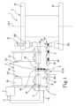
機械1は、回転カルーセル2を備える。回転カルーセル2は、第1の回転軸A1周りに回転することによって成形動作を実行するように構成されている。一実施形態では、回転カルーセル2は、複数の金型21を備える。複数の金型21の各金型は、単一の装填物D、好ましくはポリマー材料の単一の装填物Dを受け取り、その単一の装填物Dから対応する物体を成形するように構成されている。複数の金型21は、互いに角度的に離間しており且つ第1の回転軸A1から等距離にある。The
複数の金型の各金型21は、第1の部分21A(一般に雄21Aと呼ばれる)および第2の部分21B(一般に雌21Bと呼ばれる)を備える。雄21Aと雌21Bは、成形を行うために互いに対して移動可能である。より具体的には、各金型21は、開位置と閉位置との間で移動可能である。開位置では、雄21Aと雌21Bは離れており、閉位置では、雄21Aと雌21Bは接触して膨張チャンバを規定し、当該膨張チャンバに成形対象の物体の形状をとるように単一の装填物Dが流れるように構成されている。Each die 21 of the multiple dies includes a
回転カルーセル2は、互いに平行で且つ離間した第1のプレート22と第2のプレート23とを備える。各雌21Bは第1のプレート22に配置され、各雄21Aは第2のプレート23に配置される。The
一実施形態では、雄21Aは、回転カルーセル2に対して静止しており、雌21Bは、回転カルーセル2に対して、雄21Aに向かうおよび雄21Aから離れるように、移動可能である。雌21Bは、鉛直方向Vに沿って移動可能である。In one embodiment, the male 21A is stationary relative to the
この実施形態では、雄21Aは、重力方向において雌21Bの下流に、重力方向に平行な鉛直方向Vに沿って配置される。さらに、単一の装填物Dは雄21Aの金型21内に放出される。In this embodiment, the male 21A is positioned downstream of the female 21B in the direction of gravity along a vertical direction V parallel to the direction of gravity. Furthermore, a single charge D is released into the
一実施形態では、第2のプレート23は、重力方向の鉛直方向に沿って第1のプレート22の下流に配置される。一方、他の実施形態では、第1のプレート22は、重力方向の鉛直方向に沿って第2のプレート23の下流に配置される。In one embodiment, the
この実施形態は、装填物が成形される前に、雄21A上に配置された単一の装填物Dを視覚的に、または適切な検査装置によって検査することを可能にする。This embodiment allows a single charge D placed on the male 21A to be inspected visually or by a suitable inspection device before the charge is molded.
本開示はまた、雌21Bが鉛直方向Vに沿って雄21Aの下に配置される実施形態を保護することを意図していることを理解されたい。It should be understood that the present disclosure is also intended to cover embodiments in which the female 21B is disposed below the male 21A along the vertical direction V.
回転カルーセル2は、それを回転させるように構成された専用のアクチュエータによって回転駆動される。回転カルーセル2が完全に一回転するごとに、各金型21が対応する物体を製造することに留意されたい。The
複数の金型の各金型21、好ましくは各雄21Aは、供給位置PAで単一の装填物Dを受け取るように構成されている。Each die 21, preferably each male 21A, of the multiple dies is configured to receive a single load D at the feed position PA.
機械1は、フィーダ3を備える。フィーダ3は、ピックアップ位置PPから単一の装填物Dをピックアップするように構成されている。フィーダ3は、単一の装填物Dをピックアップ位置PPから供給位置PAまで搬送するように構成されている。The
一実施形態では、フィーダ3は、回転ディスク31(または回転スターホイール)を備える。回転ディスク31は、第1の回転軸A1に平行な第2の回転軸A2周りに回転する。In one embodiment, the feeder 3 comprises a rotating disk 31 (or a rotating star wheel). The
フィーダ3は、複数のピックアップ装置32を備える。複数のピックアップ装置32は、回転ディスク31に接続されている。各ピックアップ装置32は、ピックアップ位置PPで単一の装填物Dをピックアップするように構成されている。各ピックアップ装置32は、ピックアップ位置PPから供給位置PAまでの経路に沿って単一の装填物Dを移動させ続けるように構成されている。The feeder 3 includes a plurality of
本開示の一態様によれば、ピックアップ装置32は、吸引によって単一の装填物Dを保持するように構成されており、当該吸引は、ピックアップ位置PPから供給位置PAまでの経路に沿ってピックアップ装置32に対して当該装填物Dを保持するピックアップ力を当該装填物Dに加える。According to one aspect of the present disclosure, the
一実施形態では、ピックアップ装置32は、重力と同一方向に向けられた単一の装填物Dを保持するように構成されている。したがって、ピックアップ力は重力とは逆である。In one embodiment, the
ピックアップ装置32に単一の装填物Dを配置することにより、単一の装填物Dを、対応する金型21の雄21A(または雌21B)上に適切に放出することが可能になる。By placing a single load D on the
機械1は、切断要素4を備える。切断要素4は、対応する個々の装填物Dを得るために、ペースト状の材料のロッドB、好ましくはペースト状のポリマーのロッドBを切断(または分割)するように構成されている。切断要素4は、(フィーダ3の)ピックアップ装置32またはピックアップ位置PPの下流に位置する。実際には、ピックアップ装置32の上流では、単一の装填物Dはまだ存在しておらず、成形対象の材料はまだロッドBの形態である。The
一実施形態では、切断要素4は、ロッドBを個々の装填物Dに分割するように構成された単一のブレードであり、個々の装填物Dの各々は、対応するピックアップ装置32によってピックアップされる。In one embodiment, the cutting
好ましい実施形態では、切断要素4はピックアップ装置32に組み込まれている。この実施形態では、機械3は、複数の切断要素4を形成するために、各ピックアップ装置32に対して切断要素4を備える。より具体的には、特に有利な実施形態では、ピックアップ装置32および切断要素4は、切断要素4およびピックアップ装置32の機能を実行するように、すなわち、ロッドBを分割し、取得したばかりの単一の装填物Dを保持するように構成された吸引ブレード32’に組み込まれている。したがって、この実施形態では、機械1は、複数の吸引ブレード32’を備える。In a preferred embodiment, the cutting
この実施形態によれば、各吸引ブレード32’は、対応する支持ブロック32’’に蝶番で取り付けられており、当該支持ブロック32’’は回転ディスク31に接続されている。より具体的には、支持ブロック32’’は、第2の回転軸A2から等距離のそれぞれの位置で回転ディスク31に接続されている。According to this embodiment, each suction blade 32' is hinged to a corresponding support block 32'', which is connected to the
各吸引ブレード32’は、実質的に平面形状を有する吸引面321を備える。吸引面321は、複数の孔321’を含み、複数の孔321’は、空気吸引が適用され且つ対応するそれぞれの装填物Dを保持することを可能にするように構成されている。Each suction blade 32' has a
各吸引ブレード32’は、切断エッジ322を備える。切断エッジ322は、吸着面のエッジである。切断エッジ322は、ロッドBを切断して、ロッドBから、単一の装填物Dを規定する対応する部分を得るように構成されている。Each suction blade 32' includes a
各吸引ブレード32’は、吸引ブレード32’がロッドBから単一の装填物Dを切断するように構成された切断位置P1と、吸引ブレード32’がロッドBから切断したばかりの装填物Dを吸引によって保持するように構成された保持位置P2との間で、それぞれの切断軸A3周りに回転するように構成されている。Each suction blade 32' is configured to rotate about a respective cutting axis A3 between a cutting position P1, where the suction blade 32' is configured to cut a single load D from the rod B, and a holding position P2, where the suction blade 32' is configured to hold by suction the load D that has just been cut from the rod B.
切断位置P1では、各ブレード32’は、その吸引面321が第2の回転軸A2に対して垂直である(すなわち、重力方向に対して垂直である)水平面に対して垂直であるように、配置されている。このようにして、回転ディスクが回転するとき、ブレードがロッドに衝突して装填物を切断する。At the cutting position P1, each blade 32' is positioned such that its
吸引位置P2では、吸引面321は、第2の回転軸A2(すなわち重力方向)に垂直な水平面に平行である。吸引ブレード32’の吸引位置P2では、機械1は、複数の孔321’を介した吸引によって装填物Dを保持することを可能にするコンプレッサを作動させるように構成されている。In the suction position P2, the
本開示の一態様によれば、機械1は押出ユニット5を備える。押出ユニット5は、ペースト状の材料、好ましくはポリマーのロッドBを押し出すように構成されている。According to one aspect of the present disclosure, the
一実施形態では、押出ユニット5は、単一の材料のロッドを押し出すように構成されている。他の実施形態では、押出ユニット5は、1つまたは複数の異なる材料から構成されたペースト状の材料を押し出すように構成されている。In one embodiment, the extrusion unit 5 is configured to extrude a rod of a single material. In another embodiment, the extrusion unit 5 is configured to extrude a paste-like material composed of one or more different materials.
一実施形態では、押出ユニットは、第1の押出機51を備える。第1の押出機51は、第1のペースト状の材料M1を押し出すように構成されている。第1のペースト状の材料M1は、例えば、最終物体の外面および/または内面を構成することになる材料である。In one embodiment, the extrusion unit comprises a
一実施形態では、押出ユニットは、第2の押出機52を備える。第2の押出機52は、第2のペースト状の材料M2を押し出すように構成されている。第2のペースト状の材料M2は、例えば、特別な特性を有する最終物体の内層(外側に開いていない)を構成することになる材料である。特別な特性は、例えば、最終物体の内部に含まれる製品の寿命を延ばすための酸素に対する不透過性である。In one embodiment, the extrusion unit comprises a
一実施形態では、第2の材料は、酸素に対する不透過性の特性を有する材料、例えばEVOHである。In one embodiment, the second material is a material that has properties that are impermeable to oxygen, such as EVOH.
一実施形態では、押出ユニットは第3の押出機を備える。第3の押出機は、第3のペースト状の材料(相溶化材料)を押し出すように構成されている。第3の材料は、例えば、第1の材料M1と第2の材料M2との間に挟まれ且つ第1の材料M1と第2の材料M2とを適合させるように構成された、中間位置に配置された材料である。In one embodiment, the extrusion unit comprises a third extruder. The third extruder is configured to extrude a third paste-like material (compatibilizing material). The third material is, for example, a material located at an intermediate position sandwiched between the first material M1 and the second material M2 and configured to match the first material M1 and the second material M2.
一実施形態では、機械1は共押出機53を備える。共押出機53は、それぞれ第1の供給ポート511および第2の供給ポート521を通して、第1の押出機51および第2の押出機52から第1の材料M1および第2の材料M2を受け取るように構成されている。共押出機53は、第1の材料M1および第2の材料M2を含むロッドBを押し出すように構成されている。さらに、共押出機はまた、第3の相溶化材料を受け取って、それを第1の材料M1および第2の材料M2と共に押し出すように構成されている。In one embodiment, the
共押出機の例は、文献IT2019000018530に記載されており、当該文献は参照により本明細書に組み込まれる。An example of a co-extruder is described in document IT2019000018530, which is incorporated herein by reference.
一実施形態では、共押出機53は、共押出チャネル531を備える。共押出機53は、押出チャネル531と連通する1つまたは複数の注入チャネル532を備え、その中でそれぞれのペースト状の材料を搬送する。注入チャネル532は各々、ペースト状態のそれぞれの材料を押出チャネル531に注入するように構成されている。一実施形態では、複数の注入チャネル532は、押出チャネル531の両側に配置され且つ同一のペースト状の材料を注入するように構成されたチャネルの対を備える。したがって、ロッドBであって、その層が押出チャネル531に関して対称であるロッドBを生成することが可能である。In one embodiment, the co-extruder 53 comprises a
一実施形態では、1つまたは複数の注入チャネル532は、第1の材料M1を押出チャネル531に注入するように構成された一対のチャネル532’を備える。一実施形態では、1つまたは複数の注入チャネル532は、第2の材料M2を注入するように構成された少なくとも1つの中央チャネル532’’を備える。中央チャネル532’’は、第2の材料がロッドの最大展開方向に沿って断続的であるロッドBを生成するように、第2の材料を断続的に注入するように構成されている。共押出機がどのように機能するかについてのより詳細な説明は、文献IT2019000018530に記載されており、当該文献は参照により本明細書に組み込まれる。In one embodiment, the one or
したがって、共押出機は、以下に説明するさまざまな方法で具体化され得るロッドを押し出すように構成されている。The co-extruder is therefore configured to extrude rods which may be embodied in various ways as described below.
第1の実施形態では、ロッドBは平坦な多層タイプであり、第1の材料M1から作られた第1の層S1、第2の材料M2から作られた第2の層S2、および第1の材料から作られた第3の層S3を含む。多層ロッドBを有する実施形態の変形例は、さらに2つの相溶化層を含み、第1の相溶化層は第1の層と第2の層との間に位置し、第2の相溶化層は第2の層と第3の層との間に位置する。したがって、この実施形態では、ロッドBは、押出方向Eに垂直な平面に沿って(すなわち、ロッドBの最大展開方向に沿って)、実質的に長方形の断面を有する。In a first embodiment, the rod B is of the flat multi-layer type and includes a first layer S1 made of a first material M1, a second layer S2 made of a second material M2, and a third layer S3 made of the first material. A variant of the embodiment with a multi-layer rod B further includes two compatibilizing layers, the first one being located between the first and second layers, and the second one being located between the second and third layers. Thus, in this embodiment, the rod B has a substantially rectangular cross section along a plane perpendicular to the extrusion direction E (i.e. along the direction of maximum development of the rod B).
第2の実施形態では、ロッドBは、円筒状の多層タイプであり、すなわち、押出方向Eに垂直な平面に沿って(すなわち、ロッドBの最大展開方向に沿って)実質的に円形または卵形または楕円形の断面を有する。この実施形態では、ロッドBは、第1の材料M1から作られた(中空の円筒形状を有する)外側層と、第2の材料M2から作られた円形の内側コアとを備える。In a second embodiment, the rod B is of cylindrical multi-layer type, i.e. has a substantially circular or oval or elliptical cross section along a plane perpendicular to the extrusion direction E (i.e. along the direction of maximum expansion of the rod B). In this embodiment, the rod B comprises an outer layer (having a hollow cylindrical shape) made of a first material M1 and a circular inner core made of a second material M2.
ロッドBの2つの実施形態の各々は2つのタイプであり得る。すなわち、連続的に押し出された第2の材料M2を有するタイプ、または断続的に押し出された第2の材料M2を有するタイプであり得る。第2の材料M2の連続的な押出により、第2の層S2または内側コアは、押出方向Eに沿って連続的である。第2の材料M2の断続的な押出により、第2の層S2または内側コアは、押出方向Eに沿って断続的である。この場合、第2の層S2または内側コアは、第1の材料M1と第2の材料M2とを交互にすることによって形成される。Each of the two embodiments of rod B can be of two types: a type with a continuously extruded second material M2, or a type with an intermittently extruded second material M2. Due to the continuous extrusion of the second material M2, the second layer S2 or inner core is continuous along the extrusion direction E. Due to the intermittent extrusion of the second material M2, the second layer S2 or inner core is intermittent along the extrusion direction E. In this case, the second layer S2 or inner core is formed by alternating the first material M1 and the second material M2.
機械1は、検査装置6を備える。検査装置6は、ロッドBまたは装填物Dの組成を表す検査データ71を導出する(取得する)ように構成されている。検査装置6は、ロッドBまたは装填物Dの経路に沿って機械1内の種々の位置に配置され得る。より具体的には、一実施形態では、検査装置6は、押出ユニット5と切断要素4(または吸引ブレード32’)との間に配置される。これにより、検査装置はロッドBの組成を検出することができる。一実施形態では、検査装置6は、切断要素4(または吸引ブレード32’)の下流且つ供給位置PAの上流に配置され、各単一の装填物Dの組成を、当該装填物Dが対応する金型に供給される前に、検出する。The
検査装置6は、ロッドBまたは装填物Dが作られている材料の組成を特定することを可能にし、押し出されたペースト状の材料が設計仕様を満たしていることをチェックすることを可能にする。The inspection device 6 makes it possible to identify the composition of the material from which the rod B or charge D is made and to check that the extruded paste-like material meets design specifications.
一実施形態では、ロッドBまたは装填物Dに1つまたは複数の材料が存在する場合、検査データ7は、第1の材料M1または第2の材料M2の存在を表す。一実施形態では、検査データ7は、押出方向に沿って、および/または押出方向Eに垂直な横方向Tに沿って、第1の材料M1と第2の材料M2との間の相対位置を表す。In one embodiment, if one or more materials are present in the rod B or charge D, the inspection data 7 represents the presence of a first material M1 or a second material M2. In one embodiment, the inspection data 7 represents the relative position between the first material M1 and the second material M2 along the extrusion direction and/or along a transverse direction T perpendicular to the extrusion direction E.
一実施形態では、検査装置6は、複数の検査ポイント61でロッドBまたは装填物Dの組成を検出するように構成されている。したがって、検査装置6は、外側に開いているか内側にあるかにかかわらず、検査ポイント61に第2の材料M2が存在するかどうかを検出するように構成されている。In one embodiment, the inspection device 6 is configured to detect the composition of the rod B or load D at a number of inspection points 61. Thus, the inspection device 6 is configured to detect whether the second material M2 is present at the inspection points 61, whether they are open to the outside or inside.
一実施形態では、複数の検査ポイント61は、ロッドBまたは装填物Dに対してポイントごとの検査を実行することを可能にするように、互いに離間されている。In one embodiment, the multiple inspection points 61 are spaced apart from one another to allow point-by-point inspection to be performed on the rod B or load D.
この実施形態では、複数のポイント61は、横方向Tに沿って互いに離間された第1の複数のポイント群611に分割される。In this embodiment, the multiple points 61 are divided into a first group of
第1のポイント群611は、押出方向Eに平行なロッドBまたは装填物Dの側面において第2の材料M2の不在を判定することを可能にする。同時に、第1のポイント群611における検査は、ロッドBまたは装填物Dの内側の領域における第2の材料の存在を判定することを可能にする。The first group of
複数のポイント61は、押出方向Eに沿って互いに離間された第2のポイント群612に分割される。The multiple points 61 are divided into a second group of
第2の材料M2が連続的に押し出される場合、第2のポイント群612は、第2の材料M2がロッドBまたは装填物Dの押出方向Eに沿った全展開に沿って実質的に存在するかどうかを判定することを可能にする。If the second material M2 is extruded continuously, the second group of
第2の材料M2が断続的に押し出される場合、第2のポイント群612は、第2の材料M2が存在しないはずの切断領域ZTでの第2の材料M2の不在を判定することを可能にする。同時に、第2のポイント群612における検査は、フル領域、すなわち、第2の材料M2を含む領域における第2の材料の存在を判定することを可能にする。したがって、押出方向Eに沿った検査により、第2の材料M2を含まない領域が、第2の材料M2を含む領域と実質的に交互になっているかどうかをチェックすることが可能である。If the second material M2 is extruded intermittently, the second group of
一実施形態では、複数の検査ポイント61は、離間されておらず且つ押出方向Eに実質的に平行な第1の検査線L1を規定するように整列されている。一実施形態では、複数の検査ポイント61は、離間されておらず且つ横方向Tに実質的に平行な第2の検査線L2を規定するように整列されている。In one embodiment, the plurality of inspection points 61 are aligned to define a first inspection line L1 that is not spaced apart and is substantially parallel to the extrusion direction E. In one embodiment, the plurality of inspection points 61 are aligned to define a second inspection line L2 that is not spaced apart and is substantially parallel to the transverse direction T.
最後に、さらに別の実施形態では、複数の検査ポイント61は近接して、検査装置に面するロッドBまたは装填物Dの表面全体を覆う検査面を規定する。Finally, in yet another embodiment, the multiple inspection points 61 are adjacent to each other to define an inspection surface that covers the entire surface of the rod B or load D facing the inspection device.
一実施形態では、検査装置6は、電磁波、好ましくはX線を放射するように構成されたエミッタ62を備える。検査装置6は、ロッドBまたは装填物Dによる電磁波の吸収を示す(表す)吸収データを取得するように構成されたレシーバ63を備える。In one embodiment, the inspection device 6 comprises an
横方向Tに沿って離間した複数のポイントに沿って検査が行われる実施形態では、検査装置6は、2つの実施形態に従って形成され得ることを覚えておくべきである。第1の実施形態では、エミッタ62は横方向Tに沿って移動可能である。加えて、または代替的に、検査装置6は、横方向Tに沿って離間され且つ検査データを同時に取得するように構成された1つまたは複数のエミッタ62を備える。It should be remembered that in embodiments where inspection is performed along multiple points spaced along the lateral direction T, the inspection device 6 can be formed according to two embodiments. In a first embodiment, the
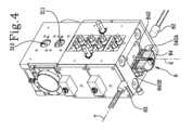
一実施形態では、検査装置6は、ガイドブロック64を備える。ガイドブロック64は、ロッドBが共押出機53から押出方向Eに沿ってスライドするスライドチャネル641を備える。ガイドブロック64は、押出ユニット5に、好ましくはロッドBが送り出される共押出機53の出口に接続されている。In one embodiment, the inspection device 6 comprises a
スライドチャネル641は、押出方向Eに沿って延在する。The
ガイドブロック64は、横断トラック642を備える。横断トラック642は、エミッタ62に面する第1の窓642Aと、レシーバ63に面する第2の窓642Bとの間でガイドブロック64をずっと横方向に走る。The
横断トラック642は、スライドチャネル641を横切る。The
一実施形態では、横断トラック642は、横方向Tおよび押出方向Eに平行なガイドブロック64の片側でも開いている。In one embodiment, the
一実施形態では、ガイドブロック64は、第1の閉鎖ドア643Aおよび/または第2の閉鎖ドア643Bを備える。第1の閉鎖ドア643Aおよび/または第2の閉鎖ドア643Bは、X線が無条件で通過することを可能にする材料、例えば、透明な材料で作られる。In one embodiment, the
一実施形態では、エミッタ62は、第1の窓642Aに実質的に垂直であり且つ好ましくは横方向Tに平行な検査方向にX線(または電磁波)を放射するように構成されている。X線は横断トラック642を通過し、スライドチャネル641に沿って移動しているロッドBと衝突する。In one embodiment, the
X線は、第2の窓642Bを通過し、横方向Tに沿って第2の窓642Bと位置合わせされたレシーバによって捕捉される。The x-rays pass through the
一実施形態では、機械1は制御ユニット7を備える。検査装置6は、検査データ71を制御ユニット7に送信するように構成されている。In one embodiment, the
制御ユニット7は、検査データ71を処理するように構成されている。制御ユニットは、対応するコマンド信号72を生成するように構成されている。制御ユニットは、コマンド信号72を切断要素4および/またはピックアップ装置32および/または回転ディスク31および/またはフィーダ3に送信するように構成されている。The control unit 7 is configured to process the
ロッドBが断続的に押し出される第2の材料M2を有するタイプである特に有利な実施形態では、検査データ71は、押出方向Eに沿った切断領域の位置を表す。In a particularly advantageous embodiment in which the rod B is of the type having an intermittently extruded second material M2, the
したがって、制御ユニット7は、切断要素4が切断領域ZTで切断を行うようにコマンド信号72を生成するように構成されている。The control unit 7 is therefore configured to generate a
加えて、または代替的に、機械1は、回転カルーセル2の下流に配置された排斥ステーションを備える。この実施形態では、制御ユニット7は、コマンド信号72を排斥ステーションに送信して、検査データ71の関数として、欠陥があることが判明した任意の物体を排斥するように排斥ステーションに指示するように構成されている。Additionally or alternatively, the
本開示の一態様によれば、この特許は、圧縮成形によってポリマー材料の物体を製造するための方法を提供する。According to one aspect of the disclosure, the patent provides a method for manufacturing an object of a polymeric material by compression molding.
方法は、回転カルーセル2を回転させるステップを含み、当該ステップでは回転カルーセル2は、第1の回転軸A1周りに回転する。The method includes a step of rotating the
方法は、回転カルーセルに取り付けられた複数の金型21がポリマー材料から物体を成形するステップを含む。複数の金型21の各金型は、単一の装填物D、好ましくはポリマー材料の単一の装填物Dを受け取り、その単一の装填物Dから対応する物体を成形する。The method includes a step in which a plurality of
成形するステップでは、各金型の雄21Aと雌21Bが互いに対して移動する。より具体的には、成形するステップは、雄21Aと雌21Bとが離間している開位置と、雄21Aと雌21Bとが接触して、成形される物体の形状をとるように単一の装填物Dが流入する膨張チャンバを規定する閉位置との間で、各金型21を移動させるステップを含む。In the molding step, the male 21A and female 21B of each mold are moved relative to one another. More specifically, the molding step includes moving each
方法の一実施形態では、雄21Aは回転カルーセル2に対して固定されたままであり、雌21Bは雄21Aに近づいたり離れたりする。雌21Bは、鉛直方向Vに沿って移動する。In one embodiment of the method, the male 21A remains fixed relative to the
方法は、単一の装填物Dが雄21Aの金型21内に放出される、装填物を放出するステップを含む。The method includes a step of discharging the charge, in which a single charge D is discharged into a
重力方向に沿って雌が雄の下に位置する方法の他の実施形態では、装填物は雌に放出される。In other embodiments of the method, where the female is positioned below the male along the direction of gravity, the load is released into the female.
方法は、専用のアクチュエータが回転カルーセル2を回転させる作動ステップを含む。The method includes an actuation step in which a dedicated actuator rotates the
回転カルーセル2の各完全な回転は、各金型21の成形の1ステップに対応することに留意されたい。したがって、回転カルーセルの各完全な回転で、製造される物体の数は、回転カルーセル2に取り付けられた金型21の数に等しい。Please note that each complete rotation of the
装填物を放出するステップでは、複数の金型の各金型21、好ましくは各雄21Aは、供給位置PAで単一の装填物Dを受け取る。In the step of discharging the load, each die 21, preferably each male 21A, of the multiple dies receives a single load D at the feed position PA.
方法は、供給ステップを含む。供給ステップでは、フィーダ3がピックアップ位置PPから単一の装填物Dをピックアップする。フィーダ3は、単一の装填物Dをピックアップ位置PPから供給位置PAまで搬送する。The method includes a feeding step, in which the feeder 3 picks up a single load D from a pick-up position PP. The feeder 3 transports the single load D from the pick-up position PP to a feed position PA.
供給ステップでは、フィーダ3の回転ディスク31(すなわち、回転スターホイール)は、第1の回転軸A1に平行な第2の回転軸A2周りに回転する。In the feeding step, the rotating disk 31 (i.e. the rotating star wheel) of the feeder 3 rotates about a second axis of rotation A2 parallel to the first axis of rotation A1.
供給ステップは、ピックアップ(すなわち、保持)ステップを含む。ピックアップステップでは、回転ディスク31に接続された複数のピックアップ装置32の各ピックアップ装置が、ピックアップ位置PPで単一の装填物Dをピックアップする。各ピックアップ装置32は、ピックアップ位置PPから供給位置PAまでの経路に沿って単一の装填物Dを移動させ続ける。The supply step includes a pick-up (i.e., holding) step, in which each of the multiple pick-up
一実施形態では、ピックアップステップは、吸引を適用するステップを含む。吸引を適用するステップでは、ピックアップ装置32は、ピックアップ位置PPから供給位置PAまでの経路に沿ってピックアップ装置32に対して単一の装填物Dを保持するピックアップ力を単一の装填物Dに適用する吸引によって単一の装填物Dを保持する。In one embodiment, the pick-up step includes a step of applying suction. In the step of applying suction, the pick-up
一実施形態では、ピックアップ装置32は、重力と同一方向に向けられた単一の装填物Dを保持する。In one embodiment, the
方法は、切断ステップを含む。切断ステップでは、切断要素4は、対応する個々の装填物Dを得るために、ペースト状の材料のロッドB、好ましくはポリマーのロッドBを切断する(すなわち、分割する)。一実施形態では、切断ステップは、(フィーダ3の)ピックアップ装置32またはピックアップ位置PPの下流の位置で、切断要素4によって実行される。The method comprises a cutting step, in which a
一実施形態では、切断要素4は、ロッドBを個々の装填物Dに切断する単一のブレードであり、その後、個々の装填物Dの各々は、対応するピックアップ装置32によってピックアップされる。In one embodiment, the cutting
一実施形態では、切断ステップおよび保持ステップは、単一のユニット(要素、構成要素)、好ましくはロッドBを切断し、切断したばかりの単一の装填物Dを保持する吸引ブレード32’によって、次々に実行される。したがって、方法のこの実施形態では、切断ステップは、複数の吸引ブレード32’によって実行される。In one embodiment, the cutting and holding steps are performed one after the other by a single unit, preferably a suction blade 32' that cuts the rod B and holds the single load D just cut. Thus, in this embodiment of the method, the cutting steps are performed by multiple suction blades 32'.
この実施形態では、各吸引ブレード32’は、対応するヒンジ周りに対応する支持ブロック32’’に対して回転する。各支持ブロック32’’は、他の支持ブロック32’’と第2の回転軸A2から同一距離の位置で回転ディスク31に接続される。In this embodiment, each suction blade 32' rotates relative to a corresponding support block 32'' about a corresponding hinge. Each support block 32'' is connected to the
各吸引ブレード32’は、複数の孔321’を介して吸引することによって装填物Dを保持する吸引面321を備える。Each suction blade 32' has a
各吸引ブレード32’は、ロッドBを切断してそこから単一の装填物Dを規定する対応する部分を得る切断エッジ322を備える。Each suction blade 32' has a
各吸引ブレード32’は、吸引ブレード32’がロッドBと衝突して単一の装填物Dを規定する部分を切断する切断位置P1と、吸引ブレード32’がロッドBから切断したばかりの装填物Dを吸引によって保持する保持位置P2との間で、それぞれの切断軸A3周りに回転する。Each suction blade 32' rotates about its respective cutting axis A3 between a cutting position P1, where the suction blade 32' collides with the rod B to cut the portion defining a single load D, and a holding position P2, where the suction blade 32' holds by suction the load D that has just been cut from the rod B.
吸引ブレード32’の吸引位置P2において、機械1は、複数の孔321’を介して吸引によって装填物Dを保持することを可能にするコンプレッサを作動させる。At the suction position P2 of the suction blade 32', the
方法は、押出ユニット5がペースト状の材料、好ましくはポリマーのロッドBを押し出すステップを含む。The method includes a step in which an extrusion unit 5 extrudes a rod B of a pasty material, preferably a polymer.
一実施形態では、押出ユニット5は、単一の材料のロッドを押し出す。他の実施形態では、押出ユニット5は、1つまたは複数の異なる材料から構成されたペースト状の材料を押し出す。In one embodiment, the extrusion unit 5 extrudes a rod of a single material. In another embodiment, the extrusion unit 5 extrudes a paste-like material composed of one or more different materials.
方法の一実施形態では、押し出すステップは、以下のステップのうちの1つまたは複数を含む。すなわち、
第1に、例えば最終物体の外面および/または内面を構成することになる第1のペースト状の材料M1を押し出すステップと、
第2に、例えば、特別な特性を有する最終物体の内層(外側に開いていない)を構成することになる第2のペースト状の材料M2、好ましくはEVOHを押し出すステップであって、特別な特性は、例えば、最終物体内に含まれる製品の寿命を延ばすための酸素に対する不透過性であるステップと、
第3に、第1の材料M1を第2の材料M2と適合させるために、例えば中間位置に位置し且つ第1の材料M1と第2の材料M2との間に挟まれた第3の材料を押し出すステップと、
第1の材料M1と第2の材料M2、および必要に応じて第3の材料を、共押出するステップと、のうちの1つまたは複数を含む。 In one embodiment of the method, the extruding step includes one or more of the following steps:
First, extruding a first pasty material M1 which will for example constitute the outer and/or inner surfaces of the final object;
secondly, extruding a second pasty material M2, preferably EVOH, which will constitute the inner layer (not open to the outside) of the final object, having special properties, for example impermeability to oxygen to increase the lifespan of the product contained in the final object;
Third, extruding a third material, for example located at an intermediate position and sandwiched between the first material M1 and the second material M2, to make the first material M1 compatible with the second material M2;
co-extruding the first material M1, the second material M2, and optionally a third material.
共押出するステップでは、共押出機53は、第1の押出機51および第2の押出機52からそれぞれ第1の材料M1および第2の材料M2を受け取る。共押出機53は、第1の材料M1および第2の材料M2を含むロッドBを押し出す。さらに、共押出機はまた、第3の相溶化材料を受け取り、それを第1の材料M1および第2の材料M2と共に押し出す。In the co-extrusion step, the co-extruder 53 receives the first material M1 and the second material M2 from the
共押出ステップの例は、文献IT2019000018530に記載されており、当該文献は、参照により本明細書に組み込まれる。An example of a co-extrusion step is described in document IT2019000018530, which is incorporated herein by reference.
共押出ステップでは、共押出機53の押出チャネル531と連通する共押出機53の1つまたは複数の注入チャネル532が、それぞれのペースト状の材料を押出チャネル531に搬送する。一実施形態では、共押出ステップでは、押出チャネル531の両側に配置された1つまたは複数の注入チャネル532のチャネルの対が、同一のペースト状の材料を注入する。したがって、ロッドBであって、その層が押出チャネル531に関して対称であるロッドBを生成することが可能である。In the co-extrusion step, one or
押出ステップでは、1つまたは複数の注入チャネル532は、第1の材料M1を押出チャネル531に注入する一対のチャネル532’を含む。一実施形態では、1つまたは複数の注入チャネル532は、第2の材料M2を押出チャネル531に注入する少なくとも1つの中央チャネル532’’を含む。In the extrusion step, the one or
方法の一実施形態では、中央チャネル532’’は、第2の材料がロッドの最大展開方向に沿って断続的であるロッドBを生成するように、第2の材料M2を断続的に注入する。この動作のために、中央チャネル532’’の流れと相互作用して第2の材料M2の流入を一時的に遮断する妨害要素が存在する。共押出機がどのように機能するかについてのより詳細な説明は、文献IT2019000018530に記載されており、当該文献は、参照により本明細書に組み込まれる。In one embodiment of the method, the central channel 532'' intermittently injects the second material M2 to produce a rod B in which the second material is intermittent along the direction of maximum expansion of the rod. For this operation, there is an obstruction element that interacts with the flow of the central channel 532'' to temporarily block the inflow of the second material M2. A more detailed description of how the co-extruder works is given in document IT2019000018530, which is incorporated herein by reference.
一実施形態では、方法は検査ステップを含む。検査ステップでは、検査装置6は、ロッドBまたは装填物Dの組成を表す検査データ71を取得(導出)する。検査ステップは、時系列に、ロッドBから物体を生成する製造プロセスのさまざまな位置で実行され得る。In one embodiment, the method includes an inspection step in which the inspection device 6 obtains (derives)
より具体的には、一実施形態では、検査ステップは、押出ステップの後、且つ切断ステップの前に実行される。このようにして、検査装置はロッドBの組成を検出する。More specifically, in one embodiment, the inspection step is performed after the extrusion step and before the cutting step. In this way, the inspection device detects the composition of rod B.
一実施形態では、検査ステップは、切断ステップの後、且つ金型21での成形ステップの前に実行される。このようにして、検査装置6は、各々の個々の装填物Dの組成を、それが対応する金型21に供給される前に、検出する。In one embodiment, the inspection step is performed after the cutting step and before the molding step in the
一実施形態では、検査ステップにおいて、押し出された材料が設計仕様を満たしていることをチェックするために、検査データ71が基準データと比較される。In one embodiment, in an inspection step, the
一実施形態では、検査ステップにおいて、検査データ71は、押出方向E(ロッドBの主の展開方向)に沿ったロッドBの特定の位置に関連付けられた基準データと比較される。一実施形態では、検査ステップにおいて、検査データ71は、押出方向E(ロッドBの主の展開方向)に垂直な横方向Tに沿ったロッドBの特定の位置に関連付けられた基準データと比較される。In one embodiment, in the inspection step, the
これにより、第1の材料M1および/または第2の材料M2が、押出方向Eに沿ったおよび/または横方向Tに沿った特定の位置に存在するか、および/または存在しないかどうかをチェックすることが可能になる。This makes it possible to check whether the first material M1 and/or the second material M2 are present and/or absent at specific positions along the extrusion direction E and/or along the transverse direction T.
一実施形態では、検査データは、押出方向に沿ったおよび/または押出方向Eに垂直な横方向Tに沿った、第1の材料M1と第2の材料M2との間の相対位置を表す。In one embodiment, the inspection data represents the relative position between the first material M1 and the second material M2 along the extrusion direction and/or along a transverse direction T perpendicular to the extrusion direction E.
検査ステップでは、検査装置6は、複数の検査ポイント61でロッドBまたは装填物Dの組成を検出する。したがって、検査装置6は、第2の材料M2が検査ポイントに存在するかどうか、第2の材料M2が外側に開いている、またはロッドBの内側にあるかどうかに関する情報を導き出す。In the inspection step, the inspection device 6 detects the composition of the rod B or the load D at a number of inspection points 61. Thus, the inspection device 6 derives information regarding whether the second material M2 is present at the inspection point, whether the second material M2 is open to the outside or inside the rod B.
一実施形態では、複数の検査ポイント61は、ロッドの離間したポイントを規定する。In one embodiment, the multiple inspection points 61 define spaced points on the rod.
一実施形態では、複数の検査ポイント61は、押出方向Eに実質的に平行な第1の検査線L1および/または横方向Tに実質的に平行な第2の検査線L2を規定する。In one embodiment, the multiple inspection points 61 define a first inspection line L1 substantially parallel to the extrusion direction E and/or a second inspection line L2 substantially parallel to the transverse direction T.
一実施形態では、複数の検査ポイント61は、検査装置6に面するロッドBの表面に対応する検査表面を規定する。In one embodiment, the plurality of inspection points 61 define an inspection surface that corresponds to the surface of the rod B facing the inspection device 6.
複数の検査ポイント61が離間している方法の実施形態では、検査装置6は、横方向Tに沿って離間している第1のポイント群611から、および/または、押出方向Eに沿って離間している第2のポイント群612から、検査データ61を取得する。In an embodiment of the method in which multiple inspection points 61 are spaced apart, the inspection device 6 acquires inspection data 61 from a first set of
第2の材料M2が断続的に押し出される場合、第2のポイント群612から取得された検査データは、第2の材料がないはずの切断領域ZTにおいて第2の材料M2が存在しないことを示す(第2の材料M2が存在しないことに関する情報を提供する、または表す)。同時に、第2のポイント群612から取得された検査データは、フル領域、すなわち、第2の材料M2を含む領域における第2の材料の存在を示す(第2の材料が存在する事に関する情報を提供する、または表す)。したがって、押出方向Eに沿った検査は、第2の材料M2を含まない領域が、第2の材料M2を含む領域と実質的に交互になっているかどうかをチェックすることを可能にする。If the second material M2 is extruded intermittently, the inspection data obtained from the second group of
検査ステップでは、検査装置6のエミッタ62が電磁波、好ましくはX線を放射する。検査装置6のレシーバ63は、ロッドBまたは装填物Dによる電磁波の吸収を示す(表す)吸収データ(屈折データ)を取得する。In the inspection step, an
方法の一実施形態では、ロッドが押出方向Eに沿って移動する間、エミッタは、第1のポイント群611から検査データ71を取得するために横方向Tに沿って移動可能である。代替的に、方法は、複数の放射ステップであって、各々が専用のエミッタ62によって実行され、各々が第1のポイント群611のそれぞれの検査ポイントに関連付けられた複数の放射ステップを含む。In one embodiment of the method, while the rod moves along the extrusion direction E, the emitter can move along the lateral direction T to acquire
検査ステップでは、ロッドは検査装置6のスライドチャネル641内を押出方向Eに沿ってスライドする。スライドチャネルは、エミッタ62およびレシーバ63に露出されている。In the inspection step, the rod slides along the extrusion direction E in the
エミッタ62は、スライドチャネル641と交差する横断トラック642へのアクセスを与える第1の窓642Aを通して検査方向にX線(または電磁波)を放射するように構成されている。X線は、横断トラック642に沿って移動してロッドBを通過し、ロッドBは、ロッドが作られている材料の組成に従って異なる条件でX線を調整する。The
X線は、レシーバ63に面する第2の窓642Bを通って横断トラック642を出る。次に、X線はレシーバ63によって捕捉される。一実施形態では、レシーバ63は、捕捉されたX線の関数として検査データ71を導き出す。The x-rays exit the
一実施形態では、方法は、制御ステップであって、制御ユニット7が検査データの関数として機械1の部分を制御する制御ステップを含む。制御ステップにおいて、検査装置6は、検査データ71を制御ユニット7に送信する。制御ユニット7は、検査データ71を処理する。制御ユニットは、対応するコマンド信号72を生成する。制御ユニットは、コマンド信号72を切断要素4および/またはピックアップ装置32および/または回転ディスク31および/またはフィーダ3に送信する。In one embodiment, the method includes a control step, in which the control unit 7 controls parts of the
ロッドBが断続的に押し出される第2の材料M2を有するタイプである特に有利な実施形態では、検査データ71は、押出方向Eに沿った切断領域の位置を表す。In a particularly advantageous embodiment in which the rod B is of the type having an intermittently extruded second material M2, the
したがって、制御ユニット7は、切断要素4が切断領域ZTで切断を行うようにコマンド信号72を生成する。The control unit 7 therefore generates a
方法は、排斥ステップであって、回転カルーセル2の下流に位置する排斥ステーションが、品質基準に適合しない成形品を排斥する排斥ステップを含む。この実施形態では、制御ユニット7は、コマンド信号72を排斥ステーションに送信して、排斥ステーションに検査データ71に基づいて欠陥があると判明した物体を排斥するように指示する。The method includes a rejection step in which a rejection station located downstream of the
Claims (21)
Translated fromJapaneseペースト状のポリマー材料のロッドを押し出すように構成された押出ユニットと、
前記ロッドを個々の装填物に分割するように構成された切断要素と、
それぞれの装填物を受け取り前記装填物から対応する物体を形成するように構成された少なくとも1つの金型と、
供給位置で前記少なくとも1つの金型に各装填物を搬送するように構成されたフィーダと、を備え、
前記ロッドまたは前記装填物の1つまたは複数の化学的または物理的特性を表す検査データを取得するように構成された検査装置を備え、
前記押出ユニットは、
第1のペースト状の材料を押し出すように構成された第1の押出機と、
第2のペースト状の材料を押し出すように構成された第2の押出機と、
前記第1の押出機および前記第2の押出機からそれぞれ前記第1の材料および前記第2の材料を受け取り、前記第1の材料および前記第2の材料を含む前記ロッドを押し出すように構成された共押出機と、を備え、
前記検査装置は、前記ロッド内の前記第2の材料の存在を検出するように構成されている、圧縮成形機械。 A compression molding machine, comprising:
an extrusion unit configured to extrude a rod of a pasty polymeric material;
a cutting element configured to divide the rod into individual charges;
at least one mold configured to receive each charge and form a corresponding object from said charge;
a feeder configured to deliver each charge to the at least one die at a feed position;
an inspection device configured to obtain inspection data indicative of one or more chemical or physical properties of the rod or the load;
The extrusion unit comprises:
a first extruder configured to extrude a first pasty material;
a second extruder configured to extrude a second pasty material;
a co-extruder configured to receive the first material and the second material from the first extruder and the second extruder, respectively, and to extrude the rod including the first material and the second material;
The inspection device is configured to detect the presence of the second material in the rod.
押出ユニットによってペースト状のポリマー材料のロッドを押し出すステップと、
前記ロッドを個々の装填物に切断するステップと、
供給位置で前記装填物を少なくとも1つの金型に供給するステップと、
前記少なくとも1つの金型で前記個々の装填物を成形することによって前記物体を形成するステップと、を含み、
検査ステップであって、検査装置が前記ロッドまたは前記装填物の組成を表す検査データを取得する検査ステップを含み、
前記押し出すステップにおいて、第1のペースト状の材料および第2のペースト状の材料を有する前記ロッドが押出され、前記検査ステップにおいて、前記検査装置は前記ロッド内の前記第2の材料の存在を検出する、方法。 1. A method for producing an object of polymeric material by compression molding, comprising:
extruding a rod of the pasty polymer material by an extrusion unit;
cutting the rod into individual charges;
delivering said charge to at least one die at a delivery location;
forming the object by molding the individual charges in the at least one mold;
an inspection step,wherein an inspection device obtains inspection data indicative of a composition of the rod or load;
A method, wherein in the extruding step, the rod having a first pasty material and a second pasty material is extruded, and in the inspecting step, the inspection device detects the presence of the second material in the rod .
ペースト状のポリマー材料のロッドを押し出すように構成された押出ユニットと、an extrusion unit configured to extrude a rod of a pasty polymeric material;
前記ロッドを個々の装填物に分割するように構成された切断要素と、a cutting element configured to divide the rod into individual charges;
それぞれの装填物を受け取り前記装填物から対応する物体を形成するように構成された少なくとも1つの金型と、at least one mold configured to receive each charge and form a corresponding object from said charge;
供給位置で前記少なくとも1つの金型に各装填物を搬送するように構成されたフィーダと、を備え、a feeder configured to deliver each charge to the at least one die at a feed position;
前記ロッドまたは前記装填物の1つまたは複数の化学的または物理的特性を表す検査データを取得するように構成された検査装置を備え、an inspection device configured to obtain inspection data indicative of one or more chemical or physical properties of the rod or the load;
前記ロッドおよび/または前記装填物は、第1の材料および第2の材料を含み、前記検査装置は前記ロッドおよび/または前記装填物の前記第1および第2の材料の少なくとも一方の存在を検出するように構成されている、圧縮成形機械。The rod and/or the charge comprises a first material and a second material, and the inspection device is configured to detect the presence of at least one of the first and second materials in the rod and/or the charge.
Applications Claiming Priority (3)
| Application Number | Priority Date | Filing Date | Title |
|---|---|---|---|
| IT102020000011947AIT202000011947A1 (en) | 2020-05-21 | 2020-05-21 | COMPRESSION MOLDING MACHINE AND METHOD |
| IT102020000011947 | 2020-05-21 | ||
| PCT/IB2021/054362WO2021234617A1 (en) | 2020-05-21 | 2021-05-20 | Compression moulding machine and method |
Publications (2)
| Publication Number | Publication Date |
|---|---|
| JP2023526648A JP2023526648A (en) | 2023-06-22 |
| JP7499357B2true JP7499357B2 (en) | 2024-06-13 |
Family
ID=71784592
Family Applications (1)
| Application Number | Title | Priority Date | Filing Date |
|---|---|---|---|
| JP2022571262AActiveJP7499357B2 (en) | 2020-05-21 | 2021-05-20 | Compression molding machine and compression molding method |
Country Status (7)
| Country | Link |
|---|---|
| US (1) | US20230182355A1 (en) |
| EP (1) | EP4153394A1 (en) |
| JP (1) | JP7499357B2 (en) |
| CN (1) | CN115943030A (en) |
| BR (1) | BR112022023472A2 (en) |
| IT (1) | IT202000011947A1 (en) |
| WO (1) | WO2021234617A1 (en) |
Families Citing this family (1)
| Publication number | Priority date | Publication date | Assignee | Title |
|---|---|---|---|---|
| EP4417390A1 (en) | 2023-02-15 | 2024-08-21 | Aisapack Holding SA | Method for producing a multilayer object and device |
Citations (3)
| Publication number | Priority date | Publication date | Assignee | Title |
|---|---|---|---|---|
| JP2005059239A (en) | 2003-08-19 | 2005-03-10 | Toyo Seikan Kaisha Ltd | Compression molding machine |
| WO2012063891A1 (en) | 2010-11-11 | 2012-05-18 | 東洋製罐株式会社 | Apparatus for correcting bending of molten resin and method for correcting bending of molten resin |
| JP2020029060A (en) | 2018-08-24 | 2020-02-27 | 株式会社名機製作所 | Compression molding system and compression molding method for reinforcing fiber-containing resin |
Family Cites Families (9)
| Publication number | Priority date | Publication date | Assignee | Title |
|---|---|---|---|---|
| US7738993B2 (en)* | 2003-10-10 | 2010-06-15 | Boston Scientific Scimed, Inc. | Extrusion of articles |
| JP5673287B2 (en)* | 2011-03-29 | 2015-02-18 | 東洋製罐株式会社 | Compression molding system |
| CN104169072B (en)* | 2011-12-29 | 2016-10-19 | 倍耐力轮胎股份公司 | Processes and equipment for building tires |
| DE102013100866B4 (en)* | 2013-01-29 | 2016-03-31 | Windmöller & Hölscher Kg | Method for the indirect determination of a specific recipe in an extrusion process and extrusion device |
| ITBO20150247A1 (en)* | 2015-05-13 | 2016-11-13 | Sacmi | APPARATUS AND METHOD OF OPTICAL INSPECTION OF AN EXTRUDER. |
| ITUB20154653A1 (en)* | 2015-10-14 | 2017-04-14 | Sacmi | Apparatus and method for processing doses. |
| IT201800000476A1 (en)* | 2018-01-03 | 2019-07-03 | Lacoplast It Srl | Unit, implant and method of coextruction |
| IT201800004832A1 (en)* | 2018-04-24 | 2019-10-24 | LINE AND METHOD FOR PRODUCING PLASTIC OBJECTS IN A CONTINUOUS CYCLE | |
| DE102019111560A1 (en)* | 2019-05-03 | 2020-11-05 | Wipotec Gmbh | Test specimen |
- 2020
- 2020-05-21ITIT102020000011947Apatent/IT202000011947A1/enunknown
- 2021
- 2021-05-20USUS17/999,318patent/US20230182355A1/enactivePending
- 2021-05-20WOPCT/IB2021/054362patent/WO2021234617A1/ennot_activeCeased
- 2021-05-20CNCN202180036762.5Apatent/CN115943030A/enactivePending
- 2021-05-20JPJP2022571262Apatent/JP7499357B2/enactiveActive
- 2021-05-20BRBR112022023472Apatent/BR112022023472A2/enactiveSearch and Examination
- 2021-05-20EPEP21727263.2Apatent/EP4153394A1/enactivePending
Patent Citations (3)
| Publication number | Priority date | Publication date | Assignee | Title |
|---|---|---|---|---|
| JP2005059239A (en) | 2003-08-19 | 2005-03-10 | Toyo Seikan Kaisha Ltd | Compression molding machine |
| WO2012063891A1 (en) | 2010-11-11 | 2012-05-18 | 東洋製罐株式会社 | Apparatus for correcting bending of molten resin and method for correcting bending of molten resin |
| JP2020029060A (en) | 2018-08-24 | 2020-02-27 | 株式会社名機製作所 | Compression molding system and compression molding method for reinforcing fiber-containing resin |
Also Published As
| Publication number | Publication date |
|---|---|
| IT202000011947A1 (en) | 2021-11-21 |
| EP4153394A1 (en) | 2023-03-29 |
| BR112022023472A2 (en) | 2022-12-20 |
| WO2021234617A1 (en) | 2021-11-25 |
| US20230182355A1 (en) | 2023-06-15 |
| CN115943030A (en) | 2023-04-07 |
| JP2023526648A (en) | 2023-06-22 |
Similar Documents
| Publication | Publication Date | Title |
|---|---|---|
| JP6720299B2 (en) | Device and method for treating dose | |
| US8753106B2 (en) | Billet carrier assembly | |
| JP7499357B2 (en) | Compression molding machine and compression molding method | |
| KR102496140B1 (en) | Coextrusion apparatus, monolayer extrusion apparatus, retrofitting kit, and process for measuring layer thickness, for manufacturing plastic film and for retrofitting extrusion apparatus | |
| JP2016118531A (en) | Three-dimensional printing inspection apparatus and method | |
| JP6990758B2 (en) | Corrugator, extrusion system and method | |
| US20210331356A1 (en) | Apparatus for compression moulding concave objects | |
| CN1925960B (en) | Multilayer materials with concave surfaces | |
| JP4670883B2 (en) | Molten resin supply apparatus, molten resin compression molding method, molten resin compression molding apparatus, and synthetic resin container manufacturing method | |
| JP2008535705A (en) | Device for transferring a predetermined amount | |
| JP7370912B2 (en) | Manufacturing method of raw roll and defect occurrence prediction method | |
| US11046004B2 (en) | Apparatus for treatment of residual thermoplastic powder | |
| JP2018065350A (en) | Pneumatic tire manufacturing apparatus | |
| KR102561326B1 (en) | Synthetic Resin Sheet Manufacturing Equipment | |
| JP6561254B2 (en) | Synthetic resin hollow plate, manufacturing apparatus and manufacturing method thereof, and extrusion molding apparatus | |
| KR101201175B1 (en) | Apparatus for producing spherical articles | |
| CN116096254A (en) | Pushing drum for the tobacco processing industry | |
| JPWO2022244032A5 (en) | ||
| ITMO20070057A1 (en) | SYSTEM FOR TRANSFERRING DOSES | |
| HK1097486B (en) | Multilayer dose having a concave surface | |
| MX2013001187A (en) | Machine for cutting corrugated hoses. |
Legal Events
| Date | Code | Title | Description |
|---|---|---|---|
| A521 | Request for written amendment filed | Free format text:JAPANESE INTERMEDIATE CODE: A523 Effective date:20221221 | |
| A621 | Written request for application examination | Free format text:JAPANESE INTERMEDIATE CODE: A621 Effective date:20221221 | |
| A131 | Notification of reasons for refusal | Free format text:JAPANESE INTERMEDIATE CODE: A131 Effective date:20231219 | |
| A521 | Request for written amendment filed | Free format text:JAPANESE INTERMEDIATE CODE: A523 Effective date:20240318 | |
| TRDD | Decision of grant or rejection written | ||
| A01 | Written decision to grant a patent or to grant a registration (utility model) | Free format text:JAPANESE INTERMEDIATE CODE: A01 Effective date:20240507 | |
| A61 | First payment of annual fees (during grant procedure) | Free format text:JAPANESE INTERMEDIATE CODE: A61 Effective date:20240603 | |
| R150 | Certificate of patent or registration of utility model | Ref document number:7499357 Country of ref document:JP Free format text:JAPANESE INTERMEDIATE CODE: R150 |