JP7498347B1 - User management system for work vehicles - Google Patents
User management system for work vehiclesDownload PDFInfo
- Publication number
- JP7498347B1 JP7498347B1JP2023185274AJP2023185274AJP7498347B1JP 7498347 B1JP7498347 B1JP 7498347B1JP 2023185274 AJP2023185274 AJP 2023185274AJP 2023185274 AJP2023185274 AJP 2023185274AJP 7498347 B1JP7498347 B1JP 7498347B1
- Authority
- JP
- Japan
- Prior art keywords
- user
- work
- work vehicle
- management system
- information
- Prior art date
- Legal status (The legal status is an assumption and is not a legal conclusion. Google has not performed a legal analysis and makes no representation as to the accuracy of the status listed.)
- Active
Links
Images


Classifications
- B—PERFORMING OPERATIONS; TRANSPORTING
- B60—VEHICLES IN GENERAL
- B60R—VEHICLES, VEHICLE FITTINGS, OR VEHICLE PARTS, NOT OTHERWISE PROVIDED FOR
- B60R25/00—Fittings or systems for preventing or indicating unauthorised use or theft of vehicles
- B60R25/01—Fittings or systems for preventing or indicating unauthorised use or theft of vehicles operating on vehicle systems or fittings, e.g. on doors, seats or windscreens
- B60R25/04—Fittings or systems for preventing or indicating unauthorised use or theft of vehicles operating on vehicle systems or fittings, e.g. on doors, seats or windscreens operating on the propulsion system, e.g. engine or drive motor
- B—PERFORMING OPERATIONS; TRANSPORTING
- B60—VEHICLES IN GENERAL
- B60R—VEHICLES, VEHICLE FITTINGS, OR VEHICLE PARTS, NOT OTHERWISE PROVIDED FOR
- B60R25/00—Fittings or systems for preventing or indicating unauthorised use or theft of vehicles
- B60R25/20—Means to switch the anti-theft system on or off
- B60R25/23—Means to switch the anti-theft system on or off using manual input of alphanumerical codes
- B—PERFORMING OPERATIONS; TRANSPORTING
- B60—VEHICLES IN GENERAL
- B60R—VEHICLES, VEHICLE FITTINGS, OR VEHICLE PARTS, NOT OTHERWISE PROVIDED FOR
- B60R25/00—Fittings or systems for preventing or indicating unauthorised use or theft of vehicles
- B60R25/20—Means to switch the anti-theft system on or off
- B60R25/24—Means to switch the anti-theft system on or off using electronic identifiers containing a code not memorised by the user
- B60R25/241—Means to switch the anti-theft system on or off using electronic identifiers containing a code not memorised by the user whereby access privileges are related to the identifiers
- G—PHYSICS
- G06—COMPUTING OR CALCULATING; COUNTING
- G06Q—INFORMATION AND COMMUNICATION TECHNOLOGY [ICT] SPECIALLY ADAPTED FOR ADMINISTRATIVE, COMMERCIAL, FINANCIAL, MANAGERIAL OR SUPERVISORY PURPOSES; SYSTEMS OR METHODS SPECIALLY ADAPTED FOR ADMINISTRATIVE, COMMERCIAL, FINANCIAL, MANAGERIAL OR SUPERVISORY PURPOSES, NOT OTHERWISE PROVIDED FOR
- G06Q10/00—Administration; Management
- G06Q10/06—Resources, workflows, human or project management; Enterprise or organisation planning; Enterprise or organisation modelling
- G06Q10/063—Operations research, analysis or management
- G06Q10/0631—Resource planning, allocation, distributing or scheduling for enterprises or organisations
- G—PHYSICS
- G06—COMPUTING OR CALCULATING; COUNTING
- G06Q—INFORMATION AND COMMUNICATION TECHNOLOGY [ICT] SPECIALLY ADAPTED FOR ADMINISTRATIVE, COMMERCIAL, FINANCIAL, MANAGERIAL OR SUPERVISORY PURPOSES; SYSTEMS OR METHODS SPECIALLY ADAPTED FOR ADMINISTRATIVE, COMMERCIAL, FINANCIAL, MANAGERIAL OR SUPERVISORY PURPOSES, NOT OTHERWISE PROVIDED FOR
- G06Q50/00—Information and communication technology [ICT] specially adapted for implementation of business processes of specific business sectors, e.g. utilities or tourism
- G06Q50/08—Construction
- G—PHYSICS
- G07—CHECKING-DEVICES
- G07C—TIME OR ATTENDANCE REGISTERS; REGISTERING OR INDICATING THE WORKING OF MACHINES; GENERATING RANDOM NUMBERS; VOTING OR LOTTERY APPARATUS; ARRANGEMENTS, SYSTEMS OR APPARATUS FOR CHECKING NOT PROVIDED FOR ELSEWHERE
- G07C5/00—Registering or indicating the working of vehicles
- G07C5/08—Registering or indicating performance data other than driving, working, idle, or waiting time, with or without registering driving, working, idle or waiting time
- B—PERFORMING OPERATIONS; TRANSPORTING
- B60—VEHICLES IN GENERAL
- B60R—VEHICLES, VEHICLE FITTINGS, OR VEHICLE PARTS, NOT OTHERWISE PROVIDED FOR
- B60R2325/00—Indexing scheme relating to vehicle anti-theft devices
- B60R2325/30—Vehicles applying the vehicle anti-theft devices
- B60R2325/308—Industrial vehicles
- G—PHYSICS
- G07—CHECKING-DEVICES
- G07C—TIME OR ATTENDANCE REGISTERS; REGISTERING OR INDICATING THE WORKING OF MACHINES; GENERATING RANDOM NUMBERS; VOTING OR LOTTERY APPARATUS; ARRANGEMENTS, SYSTEMS OR APPARATUS FOR CHECKING NOT PROVIDED FOR ELSEWHERE
- G07C9/00—Individual registration on entry or exit
- G07C9/20—Individual registration on entry or exit involving the use of a pass
- G07C9/29—Individual registration on entry or exit involving the use of a pass the pass containing active electronic elements, e.g. smartcards
Landscapes
- Engineering & Computer Science (AREA)
- Business, Economics & Management (AREA)
- Human Resources & Organizations (AREA)
- Strategic Management (AREA)
- Economics (AREA)
- Mechanical Engineering (AREA)
- Entrepreneurship & Innovation (AREA)
- General Physics & Mathematics (AREA)
- Physics & Mathematics (AREA)
- Marketing (AREA)
- Theoretical Computer Science (AREA)
- Tourism & Hospitality (AREA)
- General Business, Economics & Management (AREA)
- Development Economics (AREA)
- Educational Administration (AREA)
- Game Theory and Decision Science (AREA)
- Operations Research (AREA)
- Quality & Reliability (AREA)
- Primary Health Care (AREA)
- General Health & Medical Sciences (AREA)
- Health & Medical Sciences (AREA)
- Component Parts Of Construction Machinery (AREA)
Abstract
Translated fromJapaneseDescription
Translated fromJapanese本発明は作業用車両用ユーザ管理システムに関する。The present invention relates to a user management system for work vehicles.
建設機械等の作業用車両としては、例えば、クローラ式スキッドステアローダが広く知られている。このような作業用車両の車両本体には、先端にバケットなどのアタッチメントが着脱自在に取り付けられ上下動するアームが設けられている。そして、バケットを例えば上下に揺動させることによって、掘削した土砂の移動など種々の作業を行うことができる。なお、アタッチメントを作業目的に応じて着脱交換することにより、種々の作業を行うことができる。Crawler-type skid steer loaders, for example, are widely known as working vehicles such as construction machinery. The vehicle body of such working vehicles is provided with an arm that moves up and down and has a bucket or other attachment detachably attached to the tip. By swinging the bucket up and down, for example, various tasks can be performed, such as moving excavated soil and sand. Various tasks can be performed by attaching, detaching, and replacing the attachment depending on the work purpose.
また、この種の作業用車両は、車両上部にユーザが搭乗するキャビンが設けられている。キャビン内には、ユーザが着座するオペレータシートの近傍に、作業用車両を走行動作させるための第1の操作レバーと、バケットなどのアタッチメントを動作させるための第2の操作レバーとが設けられている(特許文献1参照)。This type of work vehicle also has a cabin on top of the vehicle where the user sits. Inside the cabin, near the operator seat where the user sits, there are a first operating lever for operating the work vehicle to travel and a second operating lever for operating an attachment such as a bucket (see Patent Document 1).
建設機械等の作業用車両のキャビンには、ユーザに作業用車両の作動状況(例えば、エンジンのオン・オフ等)を視認させるための表示装置(モニター)が設けられている(特許文献1参照)。この表示装置は、ユーザによる表示画面の切り替え操作により、表示される画面の種類が変更され、例えば水温や油温などの作業用車両の各部の状況を表示する画面や、メンテナンスに関する画面など種々の画面が表示される。A display device (monitor) is provided in the cabin of a work vehicle such as a construction machine to allow the user to visually check the operating status of the work vehicle (e.g., whether the engine is on or off) (see Patent Document 1). This display device changes the type of screen displayed when the user switches the display screen, and displays various screens, such as a screen showing the status of each part of the work vehicle, such as water temperature and oil temperature, and a screen related to maintenance.
ところで、エンジンの始動は、キーシリンダにキーを挿入して、エンジン始動位置にキーを回すことにより行われる。これは、どのユーザによっても同様の操作となっている。近年、作業の効率化を図るためにユーザの業務管理は非常に重要となってきている。また、セキュリティの観点からもユーザごとに異なるユーザ識別IDを所有させることは重要である。The engine is started by inserting a key into the key cylinder and turning it to the engine start position. This is a similar operation for all users. In recent years, it has become very important to manage user tasks in order to improve work efficiency. Also, from a security standpoint, it is important that each user has a different user identification ID.
本発明はこのような課題に鑑みてなされたものであり、セキュリティの向上を図るととも作業用車両におけるユーザの作業状況の管理を容易にすることができる作業用車両用ユーザ管理システムを提供することを目的とする。The present invention was made in consideration of these problems, and aims to provide a user management system for work vehicles that improves security and makes it easy to manage the work status of users in work vehicles.
[1]本実施形態の作業用車両用ユーザ管理システムは、作業用車両に設けられている表示部を介して入力されたユーザ情報に基づいてユーザ認証を含むユーザ管理業務を行う作業用車両用ユーザ管理システムである。作業用車両用ユーザ管理システムは、表示部を介して入力されたユーザ識別IDと、あらかじめ登録されている登録ユーザ識別IDが一致するか否かを判定する制御ユニットを有する。制御ユニットは、ユーザ識別IDと、あらかじめ登録されている登録ユーザ識別IDが一致した場合に、エンジン始動ボタンが所定時間以上押されたか否かを判定し、エンジン始動ボタンが所定時間以上押された場合に、エンジンを始動させる。したがって、ユーザ認証が成功した作業者のみエンジンの始動ができるのでセキュリティと安全性の向上が図れる。さらに、ユーザ認証により特定されたユーザとその後のエンジン始動を含めた作業履歴を紐づけできるのでより細かいユーザ管理を容易に行うことができる。
[2]本実施形態の作業用車両用ユーザ管理システムにおいて、少なくともデータベースと登録処理部を有することが好ましい。データベースは、ユーザ識別IDと、作業用車両の機構に対する設定情報を含むユーザ作業履歴情報とを有するユーザ情報を記憶する。登録処理部は、ユーザの表示部への入力を含むアクセスに応じてデータベースに記憶されたユーザ識別ID、ユーザ作業履歴情報の登録、更新を行う。登録、更新が行われたユーザ識別ID、ユーザ作業履歴情報は表示部に表示される。これにより、作業履歴情報がユーザごとに表示されるので、例えば前回使用の際の各種動作設定がわかり、その都度一から設定しなおす手間が省け、作業の効率化が図れる。
[3]本実施形態の作業用車両用ユーザ管理システムにおいて、ユーザは管理者と使用者を含み、管理者と使用者とでユーザ情報へのアクセス権限の範囲を異ならせることが好ましい。管理者と使用者の権限範囲を明確にすることにより、管理者と使用者の操作範囲が区別されるため円滑な作業管理を図ることができる。
[4]本実施形態の作業用車両用ユーザ管理システムにおいて、制御ユニットは、ユーザごとに異なるRFIDタグが配布され、当該RFIDタグに付与されているタグユーザIDと、あらかじめ登録されているタグユーザIDが一致するか否かを判定する。制御ユニットは、タグユーザIDと、あらかじめ登録されているタグユーザIDが一致した場合に、エンジン始動ボタンが所定時間以上押されたか否かを判定し、エンジン始動ボタンが所定時間以上押された場合に、エンジンを始動させる。これにより、表示部から行うユーザ認証が失敗した場合に、RFIDタグを用いた別の認証手段として機能するので、より確実にユーザ認証処理が行われる。 [1] The user management system for a work vehicle of this embodiment is a user management system for a work vehicle that performs user management tasks including user authentication based on user information input via a display unit provided on the work vehicle. The user management system for a work vehicle has a control unit that determines whether or not the user identification ID input via the display unit matches a registered user identification ID that has been registered in advance. When the user identification ID matches the registered user identification ID that has been registered in advance, the control unit determines whether or not the engine start button has been pressed for a predetermined time or more, and starts the engine when the engine start button has been pressed for a predetermined time or more. Therefore, only workers who have been successfully authenticated as users can start the engine, improving security and safety. Furthermore, since the user identified by user authentication can be linked to the work history including subsequent engine starts, more detailed user management can be easily performed.
[2] In the user management system for a work vehicle of this embodiment, it is preferable to have at least a database and a registration processing unit. The database stores user information having a user identification ID and user work history information including setting information for the mechanisms of the work vehicle. The registration processing unit registers and updates the user identification ID and user work history information stored in the database in response to access including input by the user to the display unit. The registered and updated user identification ID and user work history information are displayed on the display unit. As a result, since the work history information is displayed for each user, for example, various operation settings from the previous use can be known, eliminating the need to reset the settings from scratch each time, and improving work efficiency.
[3] In the user management system for work vehicles of this embodiment, the users include an administrator and an actual user, and it is preferable that the administrator and the actual user have different scopes of access authority to user information. By clarifying the scope of authority of the administrator and the actual user, the operational scope of the administrator and the actual user can be differentiated, which allows for smooth work management.
[4] In the user management system for work vehicles of this embodiment, a different RFID tag is distributed to each user, and the control unit determines whether the tag user ID assigned to the RFID tag matches a pre-registered tag user ID. If the tag user ID matches a pre-registered tag user ID, the control unit determines whether the engine start button has been pressed for a predetermined period of time or more, and starts the engine if the engine start button has been pressed for the predetermined period of time or more. This allows the RFID tag to function as a separate authentication means if user authentication performed via the display unit fails, thereby making user authentication processing more reliable.
本発明の作業用車両用ユーザ管理システムは、セキュリティの向上を図るとともに作業用車両におけるユーザの作業状況の管理を容易にすることができる。The user management system for work vehicles of the present invention can improve security and facilitate management of the user's work status in a work vehicle.
以下の説明において、上下左右について述べる場合には、作業用車両10の底面の側を下、底面とは反対側を上とし、作業用車両10を後面の側から見たときの当該作業用車両10の左側面の側を左、右側面の側を右とする。In the following description, when referring to up, down, left and right, the bottom side of the
[作業用車両の構成]
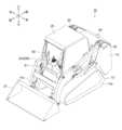
以下、本発明の実施形態について図面を参照しながら説明する。実施形態に係る作業用車両用ユーザ管理システム1については、作業用車両としてアームの先端にバケットを装着したクローラ式のスキッドステアローダを例にとって説明する。図1は、実施形態に係る作業用車両用ユーザ管理システムが搭載される作業用車両を斜め前方側から見た斜視図ある。また、実施形形態に係る作業用車両10の外観構成は、本発明の要旨となるものではないため、概略的な説明にとどめる。図2は、実施形態に係る作業用車両用ユーザ管理システム1の構成を示したブロック図である。図3は、制御ユニットの構成を示したブロック図である。図4は、データベースの構成を示したブロック図である。図5は、制御ユニットのユーザ認証処理を説明するためのフローチャートである。図6は、ユーザ認証からエンジン始動までの処理の流れを模式的に表した図である。図7は、文字等の言語設定画面を示した図である。図8は、作業用車両の各機構の動作設定画面を示した図である。図9は、ユーザの作業履歴情報画面を示した図である。なお、図2~図9において、図1に示す構成要素と同じ構成要素については同一の符号が付されている。[Configuration of work vehicle]
Hereinafter, an embodiment of the present invention will be described with reference to the drawings. The working vehicle
作業用車両10は、図1に示すように、走行装置12と、走行装置12等が搭載される本体フレーム13と、本体フレーム13の中央上部に設けられたキャビン25とを有している。走行装置12は、左右の無端状の履帯(以下、「クローラ」と呼ぶ。)11a,11b、油圧ポンプ30および油圧モータ40を有する。走行装置12が左右に取り付けられた本体フレーム13と、本体フレーム13の中央上部に設けられたキャビン25とを有している。As shown in FIG. 1, the
キャビン25は、箱状に形成さており、キャビン25内には、ユーザが車両前側に向いて着座するオペレータシート61が設けられている。キャビン25内には、シートの近傍に、作業用車両10を走行動作やバケットなどのアタッチメントを動作させるための操作レバー20(右側操作レバー20R,左側操作レバー(図示せず))が設けられている。また、操作レバー20近傍でユーザが視認しやすい位置に、ユーザからのユーザ認証処理を受け付けるメニュー画面、作業用車両の作動状況(レバー操作感度等)およびメンテナンス状況等を表示する表示部60が設けられている。この表示部60は、ユーザによる表示画面の切り替え操作により、表示される画面の種類が変更される。The
また、作業用車両10は、キャビン25の後方位置に、エンジン21(図2参照)が設けられている。エンジン21は、左右の本体フレーム13に覆われている。左右の本体フレーム13の内側には油圧ポンプ30(図2参照)や表示部60等の動作を総括的に制御するコントロールユニットとして機能する第1のECU(Electronic Control Unit:車両ECU)22(図2参照)、エンジン21を制御する第2のECU32(エンジンECU)およびバッテリー(図示せず)が設けられている。第1のECU22は、第2のECU32、油圧ポンプ30、表示部60およびバッテリーに電気的に接続されている。第2のECU32はエンジン21およびバッテリーに電気的に接続されている。The
油圧ポンプ30はエンジン21により駆動される。油圧モータ40は、左側油圧モータ140と右側油圧モータ141で構成され、油圧ポンプ30から吐出される圧油(作動油)によって回転する。油圧ポンプ30の圧油は制御部130を構成する油圧ポンプ制御部(図示せず)からの制御信号によって左側油圧モータ140と右側油圧モータ141のそれぞれに供給、排出される。左側クローラ11aは左側油圧モータ140によって駆動され、右側クローラ11bは右側油圧モータ141によって駆動される。すなわち、左側クローラ11aと右側クローラ11bは独立して駆動されるようになっている。なお、本実施例では、油圧ポンプ30が一つの場合を想定して述べているが、左側油圧モータに対応する油圧ポンプと右側油圧モータに対応する油圧ポンプの計2つを備えるものであってもよい。The
左右の油圧モータ40のそれぞれには、油圧モータ40の回転数を計測する第1の回転数センサ(図示せず),第2の回転数センサ(図示せず)が取り付けられている。第1の回転数センサおよび第2の回転数センサの検出回転数は第1のECU22へ送信される。第1のECU22は、第1及び第2の回転数センサで検出される回転数に基づくクローラ11a,11bの走行速度および後述する走行モード情報に基づいて後述する走行動作制御を行うか否かを判断する。A first rotation speed sensor (not shown) and a second rotation speed sensor (not shown) that measure the rotation speed of the
また、キャビン25の右側面上側には270度カメラ(オートバックカメラ)50が取り付けられており、左側面上側には270度カメラ(オートバックカメラ)52が取り付けられており、背面上側には270度カメラ(オートバックカメラ)54が取り付けられている。この270度カメラ(オートバックカメラ)50,52,54は作業用車両10の周囲を撮像し、その撮像データは表示部60に表示される。A 270-degree camera (auto-reverse camera) 50 is attached to the upper right side of the
[ユーザ管理システム]
以下に、図2~図5を参照してユーザからの入力情報(ユーザ情報:後述するユーザ識別情報、ユーザの作業履歴情報等)に基づいてユーザ管理を行う作業用車両用ユーザ管理システム1について説明する。[User Management System]
The following describes the work vehicle
作業用車両用ユーザ管理システム1は、第1のECU22、データベース24、第2のECU32、操作レバーセンサ27、270度カメラ50,52,54、および表示部60を有している。第1のECU22は、制御ユニット23を有している。第1のECU22は、例えば、図示しないCPU(Central Processing Unit)、ROM(Read Only Memory)、及びRAM(Random Access Memory)、入出力ポート、通信ポートを含むマイクロコンピュータで構成されている。第1のECU22に入力される信号としては、例えば、左右独立して設けられる回転数センサからの左右駆動軸の回転数情報や等が挙げられる。第1のECU22からは、各種制御信号が出力ポートを介して出力されている。第1のECU22から出力される信号としては、例えば、油圧ポンプ30への制御信号が挙げられる。The
操作レバーセンサ27は前後左右に傾動操作可能な操作レバー20(例えばジョイステック)に設けられた角度センサであり、例えばポテンショメータが挙げられる。操作レバーセンサ27は、操作レバーの操作方向が前方(直進を意味する)から左右(左右方向の移動を意味する)の範囲(180度)にあるか否かと、傾動量が所定傾動量を超えたか否かをレバー角度により検出する。例えば所定傾動量を傾動最大値(いわゆるフルレバー)に設定している場合に、操作レバーを前方に上限まで倒したときには直進かつフルレバー状態として検知される。なお、上記のような動作を検知できるものであれば検知方法はこれに限定されない。The operating
表示部60は、タッチパネルモニターであり、情報入力可能なユーザインタフェースとして機能する。このタッチパネルモニターは、ディスプレイパネルとタッチパネルを有する。ディスプレイパネルは、液晶パネルあるいは有機EL(Electro Luminescence)パネルであり、さまざまな図形情報、テキスト情報などが表示され、またボタンなどが表示される。タッチパネルは、ディスプレイパネルに重ねて設けられ、抵抗式あるいは静電容量式を用いることができる。The
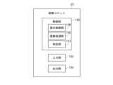
制御ユニット23は、制御部(メインコントローラー)130、入力部133、出力部134を有する。制御部130は、判定部131、登録処理部132、表示制御部136を有している。表示制御部136は、入力部133からの入力情報に基づくユーザ認証の認証結果やユーザの後述する選択情報に基づく判定部131からのエンジン始動に関する判定結果を受けて、認証結果や判定結果を表示させるための制御信号を生成して出力する。The
また、制御部130は動作制御対象である油圧ポンプ30の作動油量を調節するための制御信号を生成して出力し、作動油量が調節されることによって駆動軸の回転数が制御され、作業用車両10の走行速度やアームの上下動速度が制御される。判定部131は入力部133を介して入力されたユーザ識別情報(パスコード)がそのユーザのあらかじめ登録されているユーザ識別情報に一致するか否かを判定し、一致すれば入力したユーザが登録済ユーザであると判定される。また、判定部131は、回転数センサ、操作レバーセンサ27等からの検出結果に応じて油圧ポンプ30の吐出量を制限するか否かを判定し、その判定結果を出力する。なお、パスコードは、ユーザごとに設定され、コード変更可能な複数桁の英数字の組み合わせであるが、桁数は複数に限定されず英数字については例えば大文字小文字を含ませたりしてもよい。なお、パスコードに限らず指紋認証、音声認証、顔認証等の認証方法でユーザ識別を行うようにしてもよい。The
入力部133には、表示部60のタッチパネルを介してユーザ識別情報、ユーザ登録情報(氏名、属性等)、ユーザの各機構に対する設定情報(走行レバー感度設定、アタッチメントレバー感度設定等)を含むユーザの作業履歴情報等が入力され、加えて回転数センサおよび操作レバーセンサ27等からの検出結果が入力される。なお、属性情報はユーザが管理者(例えば各種設定情報のすべてを閲覧したり変更等できる権限を有する者)か使用者(例えば各種設定情報の一部のみ閲覧したり変更等できる権限を有する者)かを特定する情報である。出力部134からは、制御部130からの制御信号(動作制御信号、表示制御信号等)が制御対象(油圧ポンプ30、表示部60等)に出力される。データベース24は後述するユーザ認証に使用されるユーザ識別情報やユーザ登録情報を記憶するユーザ登録情報記憶部121、ユーザの作業履歴情報(作業用車両10の動作設定内容を含む)を記憶するユーザ履歴情報記憶部122を有する。登録処理部132は、あらかじめユーザ側から取得されたユーザ識別情報、ユーザ登録情報、ユーザの作業履歴情報(作業用車両10の動作設定内容を含む)をデータベース24に登録するとともに更新された場合にはデータベース24に登録済のユーザ識別情報、ユーザ登録情報、ユーザの作業履歴情報(作業用車両10の動作設定内容を含む)の更新を行う。The
表示部60は、作業用車両10のキャビン25内の運転席前方に設けられており、表示制御部136からの所定の表示制御信号に基づいてユーザ認証受付画面、ユーザの作業履歴情報画面(作業用車両10の動作設定内容を含む)等が表示される。The
[ユーザ認証処理]
以下に、具体的にどのようにユーザ認証を行うのかについて図5のフローチャートを参照して説明する。プッシュボタン72(エンジン始動ボタン:図6参照)が短押しされる(ステップS101)と、表示部60にパスコード認証画面が表示される(ステップS102)。パスコード認証画面は、図6に示すように所定桁数のパスコードを入力するように促す画面である。図6の例では、パスコード入力を促す画面が表示されているが、セキュリティを強化するためにユーザIDの入力の後にパスコードの入力を促すようにしてもよい。[User authentication process]
A specific method for performing user authentication will be described below with reference to the flowchart in Fig. 5. When the push button 72 (engine start button: see Fig. 6) is pressed briefly (step S101), a passcode authentication screen is displayed on the display unit 60 (step S102). The passcode authentication screen is a screen that prompts the user to enter a passcode of a predetermined number of digits, as shown in Fig. 6. In the example of Fig. 6, a screen that prompts the user to enter a passcode is displayed, but to enhance security, the user may be prompted to enter a passcode after entering a user ID.
ステップS103において、表示部60の表示画面にパスコードが入力されると、ステップS104において、判定部131は、入力されたパスコードとデータベース24のユーザ登録情報記憶部121に記憶されている登録済のユーザのパスコードを比較する。そして判定部131は、入力されたパスコードがそのユーザのあらかじめ登録されているパスコードに一致する場合には認証が成功したと判定され(ステップS105)、入力したユーザが登録済ユーザであると判定される。次に、判定部131は、ステップS106において、プッシュボタン72が所定時間以上長押されたか否かを判定する。プッシュボタン72が所定時間以上長押された場合には、その判定結果を受けて第2のECU32がエンジン21を始動させる(ステップS107)。その後、プッシュボタン72が長押しあるいは短押しされる(ステップS108)とアクサリー電源がオフされ(ステップS109)、処理が終了する。In step S103, when a passcode is input on the display screen of the
ステップS104に戻り、判定部131は、入力されたパスコードがそのユーザのあらかじめ登録されているパスコードに一致しない場合には認証が失敗したと判定され(ステップS112)、ステップS102の処理に戻る。Returning to step S104, if the input passcode does not match the user's pre-registered passcode, the
(変形例)
なお、ステップS102において、パスコード入力画面でそのユーザが登録済パスコードを入力しなかった場合でも、ユーザごとに異なるタグ情報を有するRFIDタグ(図6の例ではRFIDキー)71(図6参照)が配布されている場合には、このタグ情報をユーザ認証用のパスコードとして利用できる。なお、RFIDタグ71のタグ情報を読み取るRFIDタグ検出部(図示せず:読み取りリーダ)はエンジン始動ボタン72(プッシュボタン:図6参照)近傍に設けられている。RFIDタグ71には、個別ID(タグユーザID)が付与されており、使用者(作業者)等の氏名、属性等の情報がデータベース24に登録(記憶)されている。なお、属性情報は、ユーザが管理者か使用者かの区別するための情報である。(Modification)
Even if the user does not input a registered passcode on the passcode input screen in step S102, if an RFID tag (RFID key in the example of FIG. 6) 71 (see FIG. 6) having different tag information is distributed to each user, this tag information can be used as a passcode for user authentication. An RFID tag detection unit (not shown: reading reader) that reads the tag information of the RFID tag 71 is provided near the engine start button 72 (push button: see FIG. 6). An individual ID (tag user ID) is assigned to the RFID tag 71, and information such as the name and attributes of the user (operator) is registered (stored) in the
以下に、RFIDタグ71を使ったユーザ認証について図5および図6を参照して説明する。具体的には、RFIDタグ検出部(図示せず:読み取りリーダ)にRFIDタグ71をかざし(ステップS110)、判定部131は、かざしたRFIDタグ71のタグ情報と予め登録されている登録済タグ情報とが一致しているかを判定する(ステップS111)。そして判定部131は、かざしたRFIDタグ71のタグ情報がそのユーザのあらかじめ登録されているタグ情報に一致する場合には認証が成功したと判定され(ステップS105)、入力したユーザが登録済ユーザであると判定される。ステップS111において、判定部131は、入力されたパスコードがそのユーザのあらかじめ登録されているパスコードに一致しない場合には認証が失敗したと判定され(ステップS112)、ステップS102の処理に戻る。User authentication using the RFID tag 71 will be described below with reference to Figures 5 and 6. Specifically, the RFID tag 71 is held over an RFID tag detection unit (not shown: reading reader) (step S110), and the
上記した構成によれば、ユーザ認証が成功した作業者のみエンジンの始動ができるのでセキュリティと安全性の向上が図れる。さらに、表示部から行うユーザ認証が失敗した場合に、別の認証手段として機能するので、より確実にユーザ認証処理が行われる。The above configuration improves security and safety because only operators who have been successfully authenticated can start the engine. Furthermore, if user authentication via the display unit fails, it functions as a separate authentication means, so user authentication processing is performed more reliably.
[ユーザの作業履歴管理]
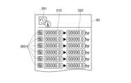
データベース24を構成するユーザ登録情報記憶部121には、上記したユーザ認証に使用されるユーザ登録情報(パスコード、RFID情報)が記憶されている。また、ユーザ履歴情報記憶部122には、ユーザの作業履歴情報が作業を行った各ユーザに紐づけされて記憶されている。この作業履歴情報は、作業者の氏名、ユーザID、作業日時、作業内容(例えば作業時間)、後述する言語設定内容、各機構の動作設定内容等であり、作業のたびにそのユーザに紐づけされて更新される。表示部60が起動されるとメニュー表示画面(図示せず)が表示され、メニュー表示画面に表示された作業履歴情報のボタン(例えばアイコン)を選択すると、例えば図9に示すような各ユーザ300の作業時間に関する作業履歴情報が表示される。図9に示す情報は作業用車両の運転開始時間310および作業用車両の運転終了時間320が表示され、今回の作業が終わればその作業時間が追加され、作業履歴情報がそのユーザに紐づけされて登録処理部132にて更新される。作業時間以外にも作業内容やユーザによる作業用車両の各機構の動作設定(走行レバー感度設定、アタッチメントレバー感度設定等)の情報(図示せず)も表示される。動作設定の詳細については後述する。なお、管理者と使用者で閲覧内容や作業履歴情報の中の利用できる情報に制限をかける(利用できる情報を区別する)ことができる。例えば、作業履歴情報の中の作業内容についての閲覧操作や使用者の登録・削除は管理者のみができて使用者はできないようにしたり、作業履歴情報の中の各機構の動作設定については使用者のみが設定できるようにすることができる。これは一例であって、操作制限(操作できる内容)は管理者と利用者のいずれかが利用可能とする設定をしてもよいし、両方が利用可能とするように設定をしてもよい。[User work history management]
The user registration
管理者と使用者で閲覧内容や作業履歴情報の中の利用できる情報に制限をかける(差を設ける)場合においては、管理者にとっては、例えば使用者の登録・削除ができるので、使用者の管理を円滑に行うことができる。また、ユーザごとに紐づけされた作業時間等の作業履歴情報を表示部60にて閲覧できるので、例えば、ある使用者の前回使用の際の各種動作設定がわかり、その使用者に対する作業の好み等がわかり使用者に対する管理の効率化を図ることができる。一方、使用者にとっては、自身の設定した過去の動作(走行レバー感度設定、アタッチメントレバー感度)を容易に把握できるので、例えば過去の設定と同じ設定を行いたい場合でも、その都度一から設定しなおすことなく短時間で設定が終了するので、作業の効率化を図ることができる。When restricting (setting differences) between the administrator and the user in the information available in the viewing content and work history information, the administrator can, for example, register and delete users, which allows for smooth management of users. In addition, work history information such as work time linked to each user can be viewed on the
[表示画面に表示される文字等の言語設定]
表示部60が起動されるとメニュー表示画面(図示せず)が表示され、メニュー表示画面に表示された言語設定情報のボタン(例えば図7に示すようなアイコン151)を選択すると、例えば図7に示すような複数の言語選択ボタン150が表示される。今回の作業が終われば、今回選択された言語の情報がそのユーザに紐づけされて更新され、次回のそのユーザによる表示部60の起動後は表示部内に表示される文字等の言語は前回選択された言語となる。これにより言語が異なる外国人でも容易に設定等を行うことができる。[Language settings for characters displayed on the display screen, etc.]
When the
[作業用車両の各機構の動作設定]
表示部60が起動されるとメニュー表示画面(図示せず)が表示され、メニュー表示画面に表示された各機構に関する動作設定ボタン(例えば図8に示すようなアイコン251)を選択すると、例えば図8に示すような複数の動作設定アイコン252,254,256および動作設定ボタン200,210,220が表示される。[Operation settings for each mechanism of the work vehicle]
When the
(走行レバー感度設定1)
動作設定ボタン200は、右側および左側の走行装置12の走行レバー感度をそれぞれ複数段階(図8では、レベルR1~レベルR10とレベルL1~レベルL10)で設定可能とするためのものである。なお、走行レバー感度を上昇させれば走行速度が上昇する。図8に示す動作設定ボタン200において、例えば、左側レベル選択ボタン337Lのタッチ回数に応じて左側レベルが上昇し、右側レベル選択ボタン337Rのタッチ回数に応じて右側レベルが上昇する。設定が完了すると、その設定された走行レバー感度は、登録処理部132により設定したユーザの情報に紐づけされてデータベース24に記憶される。(Traction lever sensitivity setting 1)
The operation setting button 200 is for enabling the travel lever sensitivity of the right and left traveling
(走行レバー感度設定2)
走行レバー感度設定ボタン(動作設定ボタン)220は、作業用車両10の走行レバー感度を例えば3段階(低感度、中感度、通常感度)で設定可能とするためのものである。なおこの段階は3段階に限られない。ユーザは、走行レバー感度設定ボタン220を押下して、自分の技量又は作業内容に応じて所望とするレベル(段階)を選択する。図8に示す走行レバー感度設定ボタン220において、例えば、走行レバー感度の選択は、左側レベル選択ボタン537Lのタッチ回数に応じて走行レバー感度のレベルが下がり、右側レベル選択ボタン537Rのタッチ回数に応じて走行レバー感度のレベルが上がる。設定が完了すると、その設定された走行レバー感度は設定したユーザの情報に紐づけされてデータベース24に記憶される。(Traction lever sensitivity setting 2)
The travel lever sensitivity setting button (operation setting button) 220 allows the travel lever sensitivity of the
(アタッチメントレバー感度設定)
アタッチメントレバー感度設定ボタン(動作設定ボタン)210は、アタッチメントレバー感度を3段階(L1~L3)で設定可能とするためのものである。なおこの段階は3段階に限られないことは言うまでもない。なお、アタッチメントレバー感度を上昇させればアタッチメントの動作速度が上昇する。図8に示す動作設定ボタン210において、例えば、アタッチメントレバー感度速度の選択は、左側レベル選択ボタン437Lのタッチ回数に応じて左側レベルが上昇し、右側レベル選択ボタン437Rのタッチ回数に応じて右側レベルが上昇する。設定が完了すると、その設定されたアタッチメントレバー感度は、登録処理部132によって設定したユーザの情報に紐づけされてデータベース24に記憶される。(Attachment lever sensitivity setting)
The attachment lever sensitivity setting button (operation setting button) 210 is for setting the attachment lever sensitivity in three stages (L1 to L3). It goes without saying that the stages are not limited to three stages. If the attachment lever sensitivity is increased, the operation speed of the attachment increases. In the operation setting button 210 shown in FIG. 8, for example, when selecting the attachment lever sensitivity speed, the left level increases according to the number of times the left level selection button 437L is touched, and the right level increases according to the number of times the right level selection button 437R is touched. When the setting is completed, the set attachment lever sensitivity is linked to the user information set by the
(その他の設定)
上記した以外にも270度カメラ50,52,54で構成される270度カメラのオンオフ設定が挙げられる。(Other settings)
In addition to the above, the on/off setting of the 270-degree camera constituted by the 270-
なお、本発明は上述の実施形態に限られるものではなく、本発明の要旨を逸脱しない範囲で種々変形実施可能となるものである。The present invention is not limited to the above-described embodiment, and various modifications can be made without departing from the spirit of the present invention.
1・・・作業用車両用ユーザ管理システム、10・・・作業用車両(クローラローダ)、11a,11b・・・無端状の履帯(クローラ)、12・・・走行装置、13・・・本体フレーム、21・・・エンジン、22・・・第1のECU、23・・・制御ユニット、24・・・データベース、25・・・キャビン、27・・・操作レバーセンサ、30・・・油圧ポンプ、32・・・第2のECU、40・・・油圧モータ、60・・・表示部、61・・・オペレータシート、71・・RFIDタグ(RFIDキー)、72・・プッシュボタン(エンジン始動ボタン)、140・・左側油圧モータ、141・・右側油圧モータ1: User management system for work vehicles, 10: Work vehicle (crawler loader), 11a, 11b: Endless tracks (crawlers), 12: Running gear, 13: Main frame, 21: Engine, 22: First ECU, 23: Control unit, 24: Database, 25: Cabin, 27: Operation lever sensor, 30: Hydraulic pump, 32: Second ECU, 40: Hydraulic motor, 60: Display, 61: Operator seat, 71: RFID tag (RFID key), 72: Push button (engine start button), 140: Left hydraulic motor, 141: Right hydraulic motor
Claims (4)
Translated fromJapanese前記表示部を介して入力されたユーザ識別IDと、あらかじめ登録されている登録ユーザ識別IDが一致するか否かを判定し、前記ユーザ識別IDと、あらかじめ登録されている登録ユーザ識別IDが一致した場合に、エンジン始動ボタンが所定時間以上押されたか否かを判定し、前記エンジン始動ボタンが所定時間以上押された場合に、エンジンを始動させる制御ユニットと、
少なくとも、前記ユーザ識別IDと、ユーザごとに紐づけされた作業時間を含む作業内容および前記作業用車両の機構に対する動作設定情報を含むユーザ作業履歴情報とを有するユーザ情報を記憶するデータベースと、
前記ユーザの前記表示部への入力を含むアクセスに応じて前記データベースに記憶された前記ユーザ識別ID、前記ユーザ作業履歴情報を、前記ユーザ作業履歴情報を前記ユーザ識別IDに紐づけして登録、更新を行う登録処理部と、を有し、
登録、更新が行われた前記ユーザ識別ID、前記ユーザ作業履歴情報は前記表示部に表示される、
ことを特徴とする作業用車両用ユーザ管理システム。 A user management system for a work vehicle, which performs user management tasks including user authentication based on user information input via a display unit provided in the work vehicle,
a control unit which determines whether a user identification ID input via the display unit matches a registered user identification ID which has been registered in advance, and if the user identification ID matches the registered user identification ID which has been registered in advance, determines whether an engine start button has been pressed for a predetermined period of time or longer, and starts an engine if the engine start button has been pressed for the predetermined period of time or longer;
a database that stores user information including at least the user identification ID, work contentincluding work time linked to each user, and user work history information including operation setting information for mechanisms of the work vehicle;
a registration processing unit that registers and updates the user identification ID and the user work history information stored in the database in response to an access including an input bythe user to the display unit, by linking the user work history information to the user identification ID,
The registered or updated user identification ID and the user work history information are displayed on the display unit.
A user management system for a work vehicle.
ことを特徴とする請求項1に記載の作業用車両用ユーザ管理システム。 The operation setting information includes at least information on a travel lever sensitivity setting of a travel device constituting the work vehicle, and information on an attachment lever sensitivity setting of an attachment constituting the work vehicle.
2. The work vehicle user management system according to claim 1, wherein the user management system is a user management system for a work vehicle.
ことを特徴とする請求項1又は2に記載の作業用車両用ユーザ管理システム。 The users include an administrator and a user, and the administrator and the user have different ranges of access authority to the user information.
3. The user management system for a work vehicle according to claim 1 or 2.
ことを特徴とする請求項1に記載の作業用車両用ユーザ管理システム。 The control unit distributes a different RFID tag to each user, and determines whether or not a tag user ID assigned to the RFID tag matches a pre-registered tag user ID. If the tag user ID matches the pre-registered tag user ID, the control unit determines whether or not an engine start button has been pressed for a predetermined period of time or longer, and starts the engine if the engine start button has been pressed for the predetermined period of time or longer.
2. The work vehicle user management system according to claim 1, wherein the user management system is a user management system for a work vehicle.
Priority Applications (3)
| Application Number | Priority Date | Filing Date | Title |
|---|---|---|---|
| JP2023185274AJP7498347B1 (en) | 2023-10-30 | 2023-10-30 | User management system for work vehicles |
| US18/414,637US12257976B1 (en) | 2023-10-30 | 2024-01-17 | User management system for working vehicle |
| EP24154993.0AEP4549259A1 (en) | 2023-10-30 | 2024-01-31 | User management system for working vehicle |
Applications Claiming Priority (1)
| Application Number | Priority Date | Filing Date | Title |
|---|---|---|---|
| JP2023185274AJP7498347B1 (en) | 2023-10-30 | 2023-10-30 | User management system for work vehicles |
Publications (2)
| Publication Number | Publication Date |
|---|---|
| JP7498347B1true JP7498347B1 (en) | 2024-06-11 |
| JP2025074460A JP2025074460A (en) | 2025-05-14 |
Family
ID=89771911
Family Applications (1)
| Application Number | Title | Priority Date | Filing Date |
|---|---|---|---|
| JP2023185274AActiveJP7498347B1 (en) | 2023-10-30 | 2023-10-30 | User management system for work vehicles |
Country Status (3)
| Country | Link |
|---|---|
| US (1) | US12257976B1 (en) |
| EP (1) | EP4549259A1 (en) |
| JP (1) | JP7498347B1 (en) |
Citations (8)
| Publication number | Priority date | Publication date | Assignee | Title |
|---|---|---|---|---|
| JP2003034235A (en) | 2001-07-24 | 2003-02-04 | Aisin Seiki Co Ltd | Vehicle anti-theft device |
| JP2005194799A (en) | 2004-01-08 | 2005-07-21 | Tokai Rika Co Ltd | Smart entry system, and method for releasing state of locking oneself out |
| JP2006117202A (en) | 2004-10-25 | 2006-05-11 | Mitsubishi Electric Corp | Moving body starting system |
| JP2016094134A (en) | 2014-11-14 | 2016-05-26 | ヤンマー株式会社 | Multipurpose vehicle |
| JP2016203744A (en) | 2015-04-20 | 2016-12-08 | 三菱電機株式会社 | Moving body environment setting device and moving body environment setting system |
| WO2019043954A1 (en) | 2017-09-04 | 2019-03-07 | 本田技研工業株式会社 | Vehicle control system |
| JP2019065634A (en) | 2017-10-03 | 2019-04-25 | 株式会社デンソー | Portable machine, authentication system, body authentication data transmission method |
| JP2021109518A (en) | 2020-01-09 | 2021-08-02 | 日立建機株式会社 | Work machine management system |
Family Cites Families (7)
| Publication number | Priority date | Publication date | Assignee | Title |
|---|---|---|---|---|
| US7123127B2 (en)* | 2003-01-31 | 2006-10-17 | General Electric Company | System for managing physical assets |
| CN100593487C (en)* | 2005-07-13 | 2010-03-10 | 小松优特力株式会社 | Operation permission control device and equipment with the same |
| JP4814281B2 (en)* | 2008-05-15 | 2011-11-16 | 三菱重工業株式会社 | Vehicle for cargo handling work and control method thereof |
| US8626407B2 (en)* | 2011-07-26 | 2014-01-07 | Kubota Corporation | Work vehicle |
| IT201700007911A1 (en)* | 2017-01-25 | 2018-07-25 | Prinoth Spa | TRACKED VEHICLE AND FLEET OF TRACKED VEHICLES |
| JP7290619B2 (en) | 2020-09-30 | 2023-06-13 | 株式会社竹内製作所 | work vehicle |
| CN118339348A (en) | 2021-12-03 | 2024-07-12 | 神钢建机株式会社 | Image display system, image display composite system, and image display method |
- 2023
- 2023-10-30JPJP2023185274Apatent/JP7498347B1/enactiveActive
- 2024
- 2024-01-17USUS18/414,637patent/US12257976B1/enactiveActive
- 2024-01-31EPEP24154993.0Apatent/EP4549259A1/enactivePending
Patent Citations (8)
| Publication number | Priority date | Publication date | Assignee | Title |
|---|---|---|---|---|
| JP2003034235A (en) | 2001-07-24 | 2003-02-04 | Aisin Seiki Co Ltd | Vehicle anti-theft device |
| JP2005194799A (en) | 2004-01-08 | 2005-07-21 | Tokai Rika Co Ltd | Smart entry system, and method for releasing state of locking oneself out |
| JP2006117202A (en) | 2004-10-25 | 2006-05-11 | Mitsubishi Electric Corp | Moving body starting system |
| JP2016094134A (en) | 2014-11-14 | 2016-05-26 | ヤンマー株式会社 | Multipurpose vehicle |
| JP2016203744A (en) | 2015-04-20 | 2016-12-08 | 三菱電機株式会社 | Moving body environment setting device and moving body environment setting system |
| WO2019043954A1 (en) | 2017-09-04 | 2019-03-07 | 本田技研工業株式会社 | Vehicle control system |
| JP2019065634A (en) | 2017-10-03 | 2019-04-25 | 株式会社デンソー | Portable machine, authentication system, body authentication data transmission method |
| JP2021109518A (en) | 2020-01-09 | 2021-08-02 | 日立建機株式会社 | Work machine management system |
Also Published As
| Publication number | Publication date |
|---|---|
| US12257976B1 (en) | 2025-03-25 |
| JP2025074460A (en) | 2025-05-14 |
| EP4549259A1 (en) | 2025-05-07 |
Similar Documents
| Publication | Publication Date | Title |
|---|---|---|
| US11634882B2 (en) | Excavator | |
| US8909387B2 (en) | Operation vehicle monitoring device | |
| EP3351692B1 (en) | Shovel | |
| KR101351200B1 (en) | Working vehicle and information display apparatus thereof | |
| JP6963007B2 (en) | Excavator, excavator display device and image display method on excavator | |
| JP6297468B2 (en) | Excavator | |
| CN113544343B (en) | Excavator | |
| US20180150070A1 (en) | Portable inspection and control device | |
| JP6615473B2 (en) | Excavator | |
| EP3173277B1 (en) | Work vehicle | |
| JP2017110472A (en) | Shovel | |
| EP4159930A1 (en) | Excavator and excavator operation device | |
| JP7379173B2 (en) | working machine | |
| CN118257313A (en) | Excavator and operating system thereof | |
| JP7498347B1 (en) | User management system for work vehicles | |
| JP2011127372A (en) | Operation mode control device for construction machine | |
| US12263808B2 (en) | Tracked vehicle and fleet of tracked vehicles | |
| JP2015131572A (en) | working machine | |
| JP2021031854A (en) | Work machine | |
| JP7704639B2 (en) | STARTING SYSTEM FOR A WORKING MACHINE, STARTING METHOD FOR A WORKING MACHINE, AND WORKING MACHINE | |
| EP4270132A1 (en) | Control system and method for controlling a first or a second agricultural machine | |
| WO2016013579A1 (en) | Working vehicle | |
| JP2024089985A (en) | Work machine management system - Patents.com | |
| JP2001295741A (en) | Work vehicle | |
| CN117651794A (en) | Work machine periphery monitoring system, work machine, and work machine periphery monitoring method |
Legal Events
| Date | Code | Title | Description |
|---|---|---|---|
| A621 | Written request for application examination | Free format text:JAPANESE INTERMEDIATE CODE: A621 Effective date:20240123 | |
| A871 | Explanation of circumstances concerning accelerated examination | Free format text:JAPANESE INTERMEDIATE CODE: A871 Effective date:20240123 | |
| A131 | Notification of reasons for refusal | Free format text:JAPANESE INTERMEDIATE CODE: A131 Effective date:20240220 | |
| A521 | Request for written amendment filed | Free format text:JAPANESE INTERMEDIATE CODE: A523 Effective date:20240321 | |
| A131 | Notification of reasons for refusal | Free format text:JAPANESE INTERMEDIATE CODE: A131 Effective date:20240416 | |
| A521 | Request for written amendment filed | Free format text:JAPANESE INTERMEDIATE CODE: A523 Effective date:20240510 | |
| TRDD | Decision of grant or rejection written | ||
| A01 | Written decision to grant a patent or to grant a registration (utility model) | Free format text:JAPANESE INTERMEDIATE CODE: A01 Effective date:20240528 | |
| A61 | First payment of annual fees (during grant procedure) | Free format text:JAPANESE INTERMEDIATE CODE: A61 Effective date:20240530 | |
| R150 | Certificate of patent or registration of utility model | Ref document number:7498347 Country of ref document:JP Free format text:JAPANESE INTERMEDIATE CODE: R150 |