JP7498209B2 - Information processing device, information processing method, and computer program - Google Patents
Information processing device, information processing method, and computer programDownload PDFInfo
- Publication number
- JP7498209B2 JP7498209B2JP2022040053AJP2022040053AJP7498209B2JP 7498209 B2JP7498209 B2JP 7498209B2JP 2022040053 AJP2022040053 AJP 2022040053AJP 2022040053 AJP2022040053 AJP 2022040053AJP 7498209 B2JP7498209 B2JP 7498209B2
- Authority
- JP
- Japan
- Prior art keywords
- image
- virtual space
- controller
- user
- unit
- Prior art date
- Legal status (The legal status is an assumption and is not a legal conclusion. Google has not performed a legal analysis and makes no representation as to the accuracy of the status listed.)
- Active
Links
Images


Classifications
- G—PHYSICS
- G06—COMPUTING OR CALCULATING; COUNTING
- G06F—ELECTRIC DIGITAL DATA PROCESSING
- G06F3/00—Input arrangements for transferring data to be processed into a form capable of being handled by the computer; Output arrangements for transferring data from processing unit to output unit, e.g. interface arrangements
- G06F3/01—Input arrangements or combined input and output arrangements for interaction between user and computer
- G06F3/011—Arrangements for interaction with the human body, e.g. for user immersion in virtual reality
- A—HUMAN NECESSITIES
- A63—SPORTS; GAMES; AMUSEMENTS
- A63F—CARD, BOARD, OR ROULETTE GAMES; INDOOR GAMES USING SMALL MOVING PLAYING BODIES; VIDEO GAMES; GAMES NOT OTHERWISE PROVIDED FOR
- A63F13/00—Video games, i.e. games using an electronically generated display having two or more dimensions
- A63F13/20—Input arrangements for video game devices
- A63F13/21—Input arrangements for video game devices characterised by their sensors, purposes or types
- A63F13/211—Input arrangements for video game devices characterised by their sensors, purposes or types using inertial sensors, e.g. accelerometers or gyroscopes
- A—HUMAN NECESSITIES
- A63—SPORTS; GAMES; AMUSEMENTS
- A63F—CARD, BOARD, OR ROULETTE GAMES; INDOOR GAMES USING SMALL MOVING PLAYING BODIES; VIDEO GAMES; GAMES NOT OTHERWISE PROVIDED FOR
- A63F13/00—Video games, i.e. games using an electronically generated display having two or more dimensions
- A63F13/40—Processing input control signals of video game devices, e.g. signals generated by the player or derived from the environment
- A63F13/42—Processing input control signals of video game devices, e.g. signals generated by the player or derived from the environment by mapping the input signals into game commands, e.g. mapping the displacement of a stylus on a touch screen to the steering angle of a virtual vehicle
- A63F13/428—Processing input control signals of video game devices, e.g. signals generated by the player or derived from the environment by mapping the input signals into game commands, e.g. mapping the displacement of a stylus on a touch screen to the steering angle of a virtual vehicle involving motion or position input signals, e.g. signals representing the rotation of an input controller or a player's arm motions sensed by accelerometers or gyroscopes
- A—HUMAN NECESSITIES
- A63—SPORTS; GAMES; AMUSEMENTS
- A63F—CARD, BOARD, OR ROULETTE GAMES; INDOOR GAMES USING SMALL MOVING PLAYING BODIES; VIDEO GAMES; GAMES NOT OTHERWISE PROVIDED FOR
- A63F13/00—Video games, i.e. games using an electronically generated display having two or more dimensions
- A63F13/50—Controlling the output signals based on the game progress
- A63F13/52—Controlling the output signals based on the game progress involving aspects of the displayed game scene
- A63F13/525—Changing parameters of virtual cameras
- A63F13/5255—Changing parameters of virtual cameras according to dedicated instructions from a player, e.g. using a secondary joystick to rotate the camera around a player's character
- A—HUMAN NECESSITIES
- A63—SPORTS; GAMES; AMUSEMENTS
- A63F—CARD, BOARD, OR ROULETTE GAMES; INDOOR GAMES USING SMALL MOVING PLAYING BODIES; VIDEO GAMES; GAMES NOT OTHERWISE PROVIDED FOR
- A63F13/00—Video games, i.e. games using an electronically generated display having two or more dimensions
- A63F13/50—Controlling the output signals based on the game progress
- A63F13/53—Controlling the output signals based on the game progress involving additional visual information provided to the game scene, e.g. by overlay to simulate a head-up display [HUD] or displaying a laser sight in a shooting game
- A63F13/533—Controlling the output signals based on the game progress involving additional visual information provided to the game scene, e.g. by overlay to simulate a head-up display [HUD] or displaying a laser sight in a shooting game for prompting the player, e.g. by displaying a game menu
- G—PHYSICS
- G02—OPTICS
- G02B—OPTICAL ELEMENTS, SYSTEMS OR APPARATUS
- G02B27/00—Optical systems or apparatus not provided for by any of the groups G02B1/00 - G02B26/00, G02B30/00
- G02B27/01—Head-up displays
- G02B27/017—Head mounted
- G—PHYSICS
- G06—COMPUTING OR CALCULATING; COUNTING
- G06F—ELECTRIC DIGITAL DATA PROCESSING
- G06F1/00—Details not covered by groups G06F3/00 - G06F13/00 and G06F21/00
- G06F1/16—Constructional details or arrangements
- G06F1/1613—Constructional details or arrangements for portable computers
- G06F1/1633—Constructional details or arrangements of portable computers not specific to the type of enclosures covered by groups G06F1/1615 - G06F1/1626
- G06F1/1684—Constructional details or arrangements related to integrated I/O peripherals not covered by groups G06F1/1635 - G06F1/1675
- G06F1/1694—Constructional details or arrangements related to integrated I/O peripherals not covered by groups G06F1/1635 - G06F1/1675 the I/O peripheral being a single or a set of motion sensors for pointer control or gesture input obtained by sensing movements of the portable computer
- G—PHYSICS
- G06—COMPUTING OR CALCULATING; COUNTING
- G06F—ELECTRIC DIGITAL DATA PROCESSING
- G06F3/00—Input arrangements for transferring data to be processed into a form capable of being handled by the computer; Output arrangements for transferring data from processing unit to output unit, e.g. interface arrangements
- G06F3/01—Input arrangements or combined input and output arrangements for interaction between user and computer
- G06F3/011—Arrangements for interaction with the human body, e.g. for user immersion in virtual reality
- G06F3/012—Head tracking input arrangements
- G—PHYSICS
- G06—COMPUTING OR CALCULATING; COUNTING
- G06F—ELECTRIC DIGITAL DATA PROCESSING
- G06F3/00—Input arrangements for transferring data to be processed into a form capable of being handled by the computer; Output arrangements for transferring data from processing unit to output unit, e.g. interface arrangements
- G06F3/01—Input arrangements or combined input and output arrangements for interaction between user and computer
- G06F3/011—Arrangements for interaction with the human body, e.g. for user immersion in virtual reality
- G06F3/013—Eye tracking input arrangements
- G—PHYSICS
- G06—COMPUTING OR CALCULATING; COUNTING
- G06F—ELECTRIC DIGITAL DATA PROCESSING
- G06F3/00—Input arrangements for transferring data to be processed into a form capable of being handled by the computer; Output arrangements for transferring data from processing unit to output unit, e.g. interface arrangements
- G06F3/01—Input arrangements or combined input and output arrangements for interaction between user and computer
- G06F3/03—Arrangements for converting the position or the displacement of a member into a coded form
- G06F3/033—Pointing devices displaced or positioned by the user, e.g. mice, trackballs, pens or joysticks; Accessories therefor
- G06F3/0346—Pointing devices displaced or positioned by the user, e.g. mice, trackballs, pens or joysticks; Accessories therefor with detection of the device orientation or free movement in a 3D space, e.g. 3D mice, 6-DOF [six degrees of freedom] pointers using gyroscopes, accelerometers or tilt-sensors
- G—PHYSICS
- G06—COMPUTING OR CALCULATING; COUNTING
- G06F—ELECTRIC DIGITAL DATA PROCESSING
- G06F3/00—Input arrangements for transferring data to be processed into a form capable of being handled by the computer; Output arrangements for transferring data from processing unit to output unit, e.g. interface arrangements
- G06F3/01—Input arrangements or combined input and output arrangements for interaction between user and computer
- G06F3/048—Interaction techniques based on graphical user interfaces [GUI]
- G06F3/0481—Interaction techniques based on graphical user interfaces [GUI] based on specific properties of the displayed interaction object or a metaphor-based environment, e.g. interaction with desktop elements like windows or icons, or assisted by a cursor's changing behaviour or appearance
- G06F3/04815—Interaction with a metaphor-based environment or interaction object displayed as three-dimensional, e.g. changing the user viewpoint with respect to the environment or object
- G—PHYSICS
- G06—COMPUTING OR CALCULATING; COUNTING
- G06F—ELECTRIC DIGITAL DATA PROCESSING
- G06F3/00—Input arrangements for transferring data to be processed into a form capable of being handled by the computer; Output arrangements for transferring data from processing unit to output unit, e.g. interface arrangements
- G06F3/01—Input arrangements or combined input and output arrangements for interaction between user and computer
- G06F3/048—Interaction techniques based on graphical user interfaces [GUI]
- G06F3/0484—Interaction techniques based on graphical user interfaces [GUI] for the control of specific functions or operations, e.g. selecting or manipulating an object, an image or a displayed text element, setting a parameter value or selecting a range
- G06F3/04842—Selection of displayed objects or displayed text elements
- G—PHYSICS
- G06—COMPUTING OR CALCULATING; COUNTING
- G06T—IMAGE DATA PROCESSING OR GENERATION, IN GENERAL
- G06T11/00—2D [Two Dimensional] image generation
- G06T11/60—Editing figures and text; Combining figures or text
- A—HUMAN NECESSITIES
- A63—SPORTS; GAMES; AMUSEMENTS
- A63F—CARD, BOARD, OR ROULETTE GAMES; INDOOR GAMES USING SMALL MOVING PLAYING BODIES; VIDEO GAMES; GAMES NOT OTHERWISE PROVIDED FOR
- A63F13/00—Video games, i.e. games using an electronically generated display having two or more dimensions
- A63F13/20—Input arrangements for video game devices
- A63F13/21—Input arrangements for video game devices characterised by their sensors, purposes or types
- A63F13/212—Input arrangements for video game devices characterised by their sensors, purposes or types using sensors worn by the player, e.g. for measuring heart beat or leg activity
- A—HUMAN NECESSITIES
- A63—SPORTS; GAMES; AMUSEMENTS
- A63F—CARD, BOARD, OR ROULETTE GAMES; INDOOR GAMES USING SMALL MOVING PLAYING BODIES; VIDEO GAMES; GAMES NOT OTHERWISE PROVIDED FOR
- A63F13/00—Video games, i.e. games using an electronically generated display having two or more dimensions
- A63F13/25—Output arrangements for video game devices
- A—HUMAN NECESSITIES
- A63—SPORTS; GAMES; AMUSEMENTS
- A63F—CARD, BOARD, OR ROULETTE GAMES; INDOOR GAMES USING SMALL MOVING PLAYING BODIES; VIDEO GAMES; GAMES NOT OTHERWISE PROVIDED FOR
- A63F13/00—Video games, i.e. games using an electronically generated display having two or more dimensions
- A63F13/85—Providing additional services to players
- A63F13/86—Watching games played by other players
- A—HUMAN NECESSITIES
- A63—SPORTS; GAMES; AMUSEMENTS
- A63F—CARD, BOARD, OR ROULETTE GAMES; INDOOR GAMES USING SMALL MOVING PLAYING BODIES; VIDEO GAMES; GAMES NOT OTHERWISE PROVIDED FOR
- A63F2300/00—Features of games using an electronically generated display having two or more dimensions, e.g. on a television screen, showing representations related to the game
- A63F2300/10—Features of games using an electronically generated display having two or more dimensions, e.g. on a television screen, showing representations related to the game characterized by input arrangements for converting player-generated signals into game device control signals
- A63F2300/1012—Features of games using an electronically generated display having two or more dimensions, e.g. on a television screen, showing representations related to the game characterized by input arrangements for converting player-generated signals into game device control signals involving biosensors worn by the player, e.g. for measuring heart beat, limb activity
- A—HUMAN NECESSITIES
- A63—SPORTS; GAMES; AMUSEMENTS
- A63F—CARD, BOARD, OR ROULETTE GAMES; INDOOR GAMES USING SMALL MOVING PLAYING BODIES; VIDEO GAMES; GAMES NOT OTHERWISE PROVIDED FOR
- A63F2300/00—Features of games using an electronically generated display having two or more dimensions, e.g. on a television screen, showing representations related to the game
- A63F2300/80—Features of games using an electronically generated display having two or more dimensions, e.g. on a television screen, showing representations related to the game specially adapted for executing a specific type of game
- A63F2300/8082—Virtual reality
- G—PHYSICS
- G02—OPTICS
- G02B—OPTICAL ELEMENTS, SYSTEMS OR APPARATUS
- G02B27/00—Optical systems or apparatus not provided for by any of the groups G02B1/00 - G02B26/00, G02B30/00
- G02B27/01—Head-up displays
- G02B27/0179—Display position adjusting means not related to the information to be displayed
- G02B2027/0187—Display position adjusting means not related to the information to be displayed slaved to motion of at least a part of the body of the user, e.g. head, eye
Landscapes
- Engineering & Computer Science (AREA)
- Theoretical Computer Science (AREA)
- General Engineering & Computer Science (AREA)
- Human Computer Interaction (AREA)
- Multimedia (AREA)
- Physics & Mathematics (AREA)
- General Physics & Mathematics (AREA)
- Computer Hardware Design (AREA)
- Optics & Photonics (AREA)
- Biophysics (AREA)
- Life Sciences & Earth Sciences (AREA)
- Health & Medical Sciences (AREA)
- Cardiology (AREA)
- General Health & Medical Sciences (AREA)
- Heart & Thoracic Surgery (AREA)
- Processing Or Creating Images (AREA)
- User Interface Of Digital Computer (AREA)
- Controls And Circuits For Display Device (AREA)
Description
Translated fromJapanese本発明は、データ処理技術に関し、特にヘッドマウントディスプレイに表示する画像を処理する技術に関する。The present invention relates to data processing technology, and in particular to technology for processing images to be displayed on a head-mounted display.
ヘッドマウントディスプレイにパノラマ画像を表示し、ヘッドマウントディスプレイを装着したユーザが頭部を回転させると視線方向に応じたパノラマ画像が表示されるようにしたシステムが開発されている。ヘッドマウントディスプレイを利用することで、仮想空間への没入感を高めることができる。A system has been developed that displays panoramic images on a head-mounted display, and when a user wearing the head-mounted display rotates their head, a panoramic image is displayed according to the direction of their line of sight. By using a head-mounted display, it is possible to increase the sense of immersion in the virtual space.
ヘッドマウントディスプレイが普及しつつある中、ヘッドマウントディスプレイを装着して仮想空間の画像(以下「VR(Virtual Reality)画像」とも呼ぶ。)を視聴するユーザに斬新な視聴体験を提供することが求められている。As head-mounted displays become more widespread, there is a demand to provide a novel viewing experience to users who wear a head-mounted display and view images in a virtual space (hereinafter referred to as "VR (Virtual Reality) images").
本発明はこうした課題に鑑みてなされたものであり、1つの目的は、VR画像を視聴するユーザに斬新な視聴体験を提供することにある。The present invention was made in consideration of these problems, and one of its objectives is to provide a novel viewing experience to users who watch VR images.
上記課題を解決するために、本発明のある態様の情報処理装置は、ヘッドマウントディスプレイに表示させる仮想空間の画像を取得する取得部と、仮想空間における撮像対象領域を示す撮像装置オブジェクトを仮想空間に配置した表示用画像を生成する画像生成部と、表示用画像をヘッドマウントディスプレイに表示させる出力部と、撮像部と、を備える。画像生成部は、ユーザが把持するコントローラの位置または姿勢の変化に応じて、仮想空間における撮像装置オブジェクトの位置または姿勢を変化させた表示用画像であり、かつ、撮像装置オブジェクトが示す撮像対象領域を変化させた表示用画像を生成し、撮像部は、撮像装置オブジェクトが示す撮像対象領域の画像を保存する。In order to solve the above problem, an information processing device according to one aspect of the present invention includes an acquisition unit that acquires an image of a virtual space to be displayed on a head-mounted display, an image generation unit that generates a display image in which an imaging device object indicating an imaging target area in the virtual space is placed in the virtual space, an output unit that displays the display image on the head-mounted display, and an imaging unit. The image generation unit generates a display image in which the position or attitude of the imaging device object in the virtual space is changed in response to a change in the position or attitude of the controller held by the user, and in which the imaging target area indicated by the imaging device object is changed, and the imaging unit saves an image of the imaging target area indicated by the imaging device object.
本発明の別の態様は、情報処理方法である。この方法は、ヘッドマウントディスプレイに表示させる仮想空間の画像を取得するステップと、仮想空間における撮像対象領域を示す撮像装置オブジェクトを仮想空間に配置した表示用画像を生成するステップと、表示用画像をヘッドマウントディスプレイに表示させるステップと、をコンピュータが実行し、生成するステップは、ユーザが把持するコントローラの位置または姿勢の変化に応じて、仮想空間における撮像装置オブジェクトの位置または姿勢を変化させた表示用画像であり、かつ、撮像装置オブジェクトが示す撮像対象領域を変化させた表示用画像を生成し、撮像装置オブジェクトが示す撮像対象領域の画像を保存するステップをコンピュータがさらに実行する。Another aspect of the present invention is an information processing method. In this method, a computer executes the steps of acquiring an image of a virtual space to be displayed on a head-mounted display, generating a display image in which an imaging device object indicating an imaging target area in the virtual space is placed in the virtual space, and displaying the display image on the head-mounted display. The generating step is a display image in which the position or attitude of the imaging device object in the virtual space is changed in response to a change in the position or attitude of the controller held by the user, and the computer further executes the steps of generating a display image in which the imaging target area indicated by the imaging device object is changed, and saving an image of the imaging target area indicated by the imaging device object.
なお、以上の構成要素の任意の組合せ、本発明の表現をシステム、コンピュータプログラム、コンピュータプログラムを読み取り可能に記録した記録媒体、データ構造などの間で変換したものもまた、本発明の態様として有効である。In addition, any combination of the above components, and conversions of the present invention between a system, a computer program, a recording medium on which a computer program is readably recorded, a data structure, etc. are also valid aspects of the present invention.
本発明によれば、VR画像を視聴するユーザに斬新な視聴体験を提供することができる。The present invention can provide a novel viewing experience to users who view VR images.
図1は、実施例に係るヘッドマウントディスプレイの外観図である。ヘッドマウントディスプレイ100は、本体部110、前頭部接触部120、および側頭部接触部130を含む。ヘッドマウントディスプレイ100は、ユーザの頭部に装着してディスプレイに表示される静止画や動画などを鑑賞し、ヘッドホンから出力される音声や音楽などを聴くための表示装置である。ヘッドマウントディスプレイ100の形状に制限はなく、例えば、帽子型でもよく、眼鏡型でもよい。Figure 1 is an external view of a head mounted display according to an embodiment. The head mounted
実施例では、ヘッドマウントディスプレイ100に内蔵または外付けされたモーションセンサにより、ヘッドマウントディスプレイ100を装着したユーザの頭部の回転角や傾きといった姿勢情報およびユーザの視線を計測する。変形例として、ユーザがモーションセンサを頭部に装着したり、注視点検出装置を用いて赤外線の反射を検出したりすることで視線を検出してもよい。あるいは、ヘッドマウントディスプレイまたはユーザの頭部にマーカーを装着させ、その姿を撮影した画像を解析することにより、ヘッドマウントディスプレイまたはユーザの姿勢と視線を推定してもよい。In the embodiment, a motion sensor built into or attached to the head mounted
図2は、図1のヘッドマウントディスプレイ100の機能構成を示すブロック図である。本明細書のブロック図で示す複数の機能ブロックは、ハードウェア的には、回路ブロック、メモリ、その他のLSIで構成することができ、ソフトウェア的には、メモリにロードされたプログラムをCPUが実行すること等によって実現される。したがって、これらの機能ブロックがハードウェアのみ、ソフトウェアのみ、またはそれらの組合せによっていろいろな形で実現できることは当業者には理解されるところであり、いずれかに限定されるものではない。Figure 2 is a block diagram showing the functional configuration of the head mounted
制御部10は、画像信号、センサ信号などの信号や、命令やデータを処理して出力するメインプロセッサである。入力インタフェース20は、ユーザからの操作信号や設定信号を受け付け、制御部10に供給する。出力インタフェース30は、制御部10から画像信号を受け取り、ディスプレイに表示させる。バックライト32は、液晶ディスプレイにバックライトを供給する。The
通信制御部40は、ネットワークアダプタ42またはアンテナ44を介して、有線または無線通信により、制御部10から入力されるデータを外部に送信する。通信制御部40は、また、ネットワークアダプタ42またはアンテナ44を介して、有線または無線通信により、外部からデータを受信し、制御部10に出力する。記憶部50は、制御部10が処理するデータやパラメータ、操作信号などを一時的に記憶する。The
モーションセンサ64は、ヘッドマウントディスプレイ100の本体部110の回転角や傾きなどの姿勢情報を検出する。モーションセンサ64は、ジャイロセンサ、加速度センサ、角加速度センサなどを適宜組み合わせて実現される。外部入出力端子インタフェース70は、周辺機器を接続するためのインタフェースであり、例えばUSB(Universal Serial Bus)コントローラである。外部メモリ72は、フラッシュメモリなどの外部メモリである。The
時計部80は、制御部10からの設定信号によって時間情報を設定し、時間データを制御部10に供給する。制御部10は、画像やテキストデータを出力インタフェース30に供給してディスプレイに表示させたり、通信制御部40に供給して外部に送信させたりすることができる。The
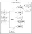
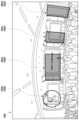
図3は、実施例に係るエンタテインメントシステムの構成図である。エンタテインメントシステム300は、現在行われているコンサートやカンファレンスの映像を、ユーザが装着したヘッドマウントディスプレイ100に表示させる情報処理システムである。Figure 3 is a configuration diagram of an entertainment system according to an embodiment. The entertainment system 300 is an information processing system that displays video of a currently ongoing concert or conference on a head-mounted
情報処理装置200は、ヘッドマウントディスプレイ100の表示内容を制御する据置型ゲーム機である。変形例として、情報処理装置200は、PC、タブレット端末、スマートフォン、携帯型ゲーム機であってもよい。また、情報処理装置200は、ヘッドマウントディスプレイ100と一体化されてもよく、言い換えれば、情報処理装置200の機能は、ヘッドマウントディスプレイ100に組み込まれてもよい。The
情報処理装置200は、無線通信またはUSBなどの周辺機器を接続するインタフェースを介してヘッドマウントディスプレイ100およびコントローラ202に接続される。また、情報処理装置200は、LAN・WAN・インターネット等を含む通信網308を介して、管理サーバ304、SNSサーバ306、ライブ配信システム302の配信サーバ312と接続される。The
コントローラ202は、ヘッドマウントディスプレイ100を装着したユーザが把持するものであり、情報処理装置200に対するユーザの操作を受け付け、その操作内容を情報処理装置200へ送信する。また、コントローラ202は、モーションセンサを備える。モーションセンサは、コントローラ202の回転角や傾きなどの姿勢情報を検出する。このモーションセンサは、ジャイロセンサ、加速度センサ、角加速度センサなどを適宜組み合わせて実現される。The
ライブ配信システム302は、現在行われている様々なイベント(例えばコンサートやカンファレンス等)の映像を、複数のユーザの複数の情報処理装置200へ配信する情報処理システムである。ライブ配信システム302は、複数の全天球カメラ310(例えば全天球カメラ310a、全天球カメラ310b、全天球カメラ310c)と、配信サーバ312を含む。The
全天球カメラ310は、イベントが実施されている会場(例えば屋内または野外のコンサート会場やカンファレンス会場)に配置され、上下左右全方位のパノラマ画像を撮像する。全天球カメラ310は、全方位カメラまたは360度カメラとも言える。配信サーバ312は、複数の全天球カメラ310により撮像された複数のパノラマ画像のデータを取得する。配信サーバ312は、複数の全天球カメラ310のうちユーザにより選択された全天球カメラ310により撮像されたパノラマ画像のデータを情報処理装置200へ送信する。The
管理サーバ304は、アカウント制のオンラインサービス(例えば複数のユーザのコミュニティサービス)を提供する情報処理装置である。管理サーバ304は、ユーザのフレンドに関する情報を情報処理装置200へ提供し、また、複数のユーザ(情報処理装置200)間で送受信されるデータを中継する。SNSサーバ306は、ソーシャル・ネットワーキング・サービスを提供する情報処理装置である。例えば、SNSサーバ306は、画像共有サービス、ミニブログサービス、チャットサービスを提供する。エンタテインメントシステム300は、複数のSNS業者の複数のSNSサーバ306を含んでよい。The
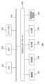
図4は、図3の情報処理装置200の内部回路構成を示す。情報処理装置200は、CPU(Central Processing Unit)222、GPU(Graphics Processing Unit)224、メインメモリ226を含む。これらの各部は、バス230を介して相互に接続されている。バス230にはさらに入出力インタフェース228が接続されている。Figure 4 shows the internal circuit configuration of the
入出力インタフェース228には、USBやIEEE1394などの周辺機器インタフェースや、有線又は無線LANのネットワークインタフェースからなる通信部232、ハードディスクドライブや不揮発性メモリなどの記憶部234、ヘッドマウントディスプレイ100などの表示装置へデータを出力する出力部236、ヘッドマウントディスプレイ100からデータを入力する入力部238、磁気ディスク、光ディスクまたは半導体メモリなどのリムーバブル記録媒体を駆動する記録媒体駆動部240が接続される。Connected to the input/
CPU222は、記憶部234に記憶されているオペレーティングシステムを実行することにより情報処理装置200の全体を制御する。CPU222はまた、リムーバブル記録媒体から読み出されてメインメモリ226にロードされた、あるいは通信部232を介してダウンロードされた各種プログラムを実行する。GPU224は、ジオメトリエンジンの機能とレンダリングプロセッサの機能とを有し、CPU222からの描画命令に従って描画処理を行い、表示画像を図示しないフレームバッファに格納する。そしてフレームバッファに格納された表示画像をビデオ信号に変換して出力部236に出力する。メインメモリ226はRAM(Random Access Memory)により構成され、処理に必要なプログラムやデータを記憶する。The
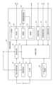
図5は、図3の情報処理装置200の機能構成を示すブロック図である。情報処理装置200は、コンポーネント記憶部320、撮像画像記憶部322、画像取得部330、関連情報取得部332、フレンド情報取得部334、位置・姿勢取得部336、視野制御部338、操作検出部340、コンテンツ処理部342、画像生成部344、出力部346を備える。これらの機能のうち少なくとも一部は、ヘッドマウントディスプレイ100(図2の制御部10、記憶部50等)に実装されてもよく、あるいは、ネットワークを介して接続されたサーバ(配信サーバ312等)に実装されてもよい。Figure 5 is a block diagram showing the functional configuration of the
図5の複数の機能ブロックのうち少なくとも一部は、各機能ブロックに対応するモジュールを含むコンピュータプログラム(例えばライブストリーミング視聴アプリケーション)として実装されてもよい。このコンピュータプログラムは、DVD等の記録メディアに格納され、または、ネットワークからダウンロードされて、情報処理装置200の記憶部234にインストールされてもよい。情報処理装置200のCPU222およびGPU224は、このコンピュータプログラムをメインメモリ226に読み出して実行することにより、各機能ブロックの機能を発揮してもよい。At least some of the multiple functional blocks in FIG. 5 may be implemented as a computer program (e.g., a live streaming viewing application) including modules corresponding to each functional block. This computer program may be stored on a recording medium such as a DVD, or downloaded from a network and installed in the
コンポーネント記憶部320は、VR画像内で表示される複数種類のコンポーネントのそれぞれについて、形状や表示内容等に関するデータを記憶する。コンポーネントは、仮想空間のコンテンツ(例えばイベントの内容や、演者、登壇者等)に関連した様々な情報を表示するGUI部品である。コンポーネントは、サブウィンドウ、パネル、またはダッシュボードとも言える。撮像画像記憶部322は、後述の撮像部352により生成された画像データを記憶する。The
画像取得部330は、配信サーバ312から送信された、ヘッドマウントディスプレイ100に表示させる仮想空間のデータを取得する。即ち、画像取得部330は、仮想空間の画像を取得する第1取得部を構成している。仮想空間のデータは、全天球カメラ310により撮像されたパノラマ画像のデータを含む。また、仮想空間のデータは、撮像されたイベントの内容やスケジュール、演者・登壇者に関する情報、撮像場所を示す情報等、撮像対象に関する様々な情報である撮像対象情報を含む。The
関連情報取得部332は、ヘッドマウントディスプレイ100で表示される仮想空間に関連する複数種類の情報(以下「関連情報」とも呼ぶ。)を配信サーバ312、SNSサーバ306から取得する。即ち、関連情報取得部332は、第2取得部を構成している。関連情報は、ライブ配信されたメインのコンテンツ(イベントの様子等)に関連する付加的・付随的な情報であり、即時性のある情報を含む。例えば、関連情報は、(1)第2画面用の画像データ、(2)ヒートマップのデータ、(3)演者や登壇者に関するデータ、(4)イベントのスケジュール、(5)イベントに関連づけられたミニブログの投稿データ、(6)ニュースサイトやブログサイト等のフィードデータであってもよい。実施例では、関連情報は、コンポーネント上に表示される。The related
フレンド情報取得部334は、ユーザが予め設定した1人以上のフレンドに関する情報(以下「フレンド情報」とも呼ぶ。)を管理サーバ304から取得する。フレンド情報は、1人以上のフレンドそれぞれについてのアバター情報、オンラインの有無、ヘッドマウントディスプレイ100の起動有無、ヘッドマウントディスプレイ100の姿勢(言い換えればフレンドの視線方向)の少なくとも1つを含んでもよい。The friend
位置・姿勢取得部336は、ヘッドマウントディスプレイ100の位置および/または姿勢を取得する。位置・姿勢取得部336は、ヘッドマウントディスプレイ100のモーションセンサ64の検出値に基づいて、ヘッドマウントディスプレイ100を装着したユーザの頭部の位置や姿勢を所定のレートで検出する。The position and
位置は、現実世界の3次元空間においてヘッドマウントディスプレイ100が存在する位置を示す座標であってもよい。姿勢は、縦方向、横方向、高さ方向の3軸におけるヘッドマウントディスプレイ100の傾きであってもよい。位置・姿勢取得部336は、情報処理装置200に接続した図示しない撮像装置による撮像画像に基づき、頭部の位置や姿勢を取得してもよく、その結果をモーションセンサによる情報と統合してもよい。The position may be coordinates indicating the position where the head mounted
なお、位置・姿勢取得部336により取得されたヘッドマウントディスプレイ100の位置および姿勢は、不図示の送信部により、管理サーバ304へ定期的にアップロードされてもよい。管理サーバ304は、或るユーザの情報処理装置200からアップロードされたヘッドマウントディスプレイ100の位置および姿勢の情報を当該ユーザのフレンドの情報処理装置200へ提供してもよい。これにより、複数のユーザ間(フレンド間)で、ヘッドマウントディスプレイ100の位置および姿勢を共有することができる。The position and orientation of the head mounted
また、位置・姿勢取得部336は、コントローラ202の位置および/または姿勢を取得する。位置・姿勢取得部336は、コントローラ202に内蔵されたモーションセンサの検出値に基づいて、コントローラ202の位置や姿勢を所定のレートで検出する。なお、位置・姿勢取得部336は、情報処理装置200に接続した図示しない撮像装置による撮像画像に基づき、コントローラ202の位置や姿勢を取得してもよく、その結果をモーションセンサによる情報と統合してもよい。The position and
視野制御部338は、ユーザの視線に基づき表示画像の視野を制御する。視野制御部338は、位置・姿勢取得部336により取得された頭部の位置および/または姿勢に基づいて、ユーザの視野の範囲を決定する。視野制御部338は、描画対象の3次元空間に対する視野面(スクリーン)を設定する。The field of
例えば、パノラマ画像が示す仮想空間に、空中に浮かぶコンポーネントとユーザの頭部を包含するような大きさの全天球状の背景オブジェクトを、一般的なコンピュータグラフィックスと同様のグローバル座標系に定義してもよい。これにより空間に奥行き感が生じ、コンポーネントが空中に浮いている状態、もしくは、仮想空間の背景(例えば壁や天井等)に貼り付いた状態をより印象づけられる。視野制御部338は、当該グローバル座標系に対するスクリーン座標を、ヘッドマウントディスプレイ100の姿勢に基づいて所定のレートで設定してもよい。For example, in the virtual space shown by the panoramic image, a spherical background object large enough to encompass the components floating in the air and the user's head may be defined in a global coordinate system similar to that used in general computer graphics. This creates a sense of depth in the space, giving the impression that the components are floating in the air or attached to the background of the virtual space (e.g., a wall or ceiling). The field of
ヘッドマウントディスプレイ100の姿勢、すなわちユーザ頭部のオイラー角によってユーザの顔面の向く方向が判明する。視野制御部338は少なくとも、当該顔面の向く方向に対応させてスクリーン座標を設定することにより、ユーザが向く方向に応じた視野で仮想空間がスクリーン平面に描画されるようにする。この場合、ユーザの顔面の法線ベクトルをおよそ視線の方向と推定していることになる。The orientation of the head mounted
なお赤外線の反射などにより注視点を検出する装置を用いればさらに詳細な視線情報を得ることができる。以後の説明では、導出手法によらず推定あるいは検出された、ユーザが見ている方向を総じて「視線」の方向と称する。視野制御部338は、ユーザ頭部の姿勢の変化が所定の値を超えるまでは検出された角度の変化を無視するようにして、意図せず画像がぶれるのを防いでもよい。また、表示画像のズーム操作を受け付けるような場合は、ズーム倍率に基づいて頭部の角度検出の感度を調整してもよい。More detailed gaze information can be obtained by using a device that detects the gaze point by, for example, reflecting infrared light. In the following explanation, the direction in which the user is looking, estimated or detected regardless of the derivation method, will be collectively referred to as the "gaze" direction. The field of
操作検出部340は、コントローラ202から受信した信号に基づいて、ユーザがコントローラ202に入力した操作を検出する。操作検出部340は、コントローラ202に入力された操作と、当該操作の対象(VR画像内のオブジェクト等)に応じて、ユーザにより指示された動作および/または処理をユーザ操作として識別する。ユーザ操作は、例えば、メニューアイコンの選択、コンポーネントの選択、コンポーネントの操作、カメラ操作、SNS投稿操作を含む。また、操作検出部340は、位置・姿勢取得部336により検出されたコントローラ202の位置や姿勢もユーザ操作として検出する。The
コンテンツ処理部342は、操作検出部340により検出されたユーザ操作に応じて、各種データ処理を実行する。コンテンツ処理部342は、要求部350、撮像部352、登録部354を含む。要求部350は、配信サーバ312に対してライブ配信に関する要求を送信する。また、要求部350は、管理サーバ304に対してユーザ情報の提供を要求する。The
撮像部352は、後述のカメラオブジェクトにより指定された撮像対象領域の画像を撮像画像として生成し、撮像画像記憶部322に格納する。登録部354は、撮像画像記憶部322に格納された1つ以上の撮像画像のうちユーザにより指定された撮像画像をSNSサーバ306へ登録する。これにより、登録部354は、SNSを利用する他のユーザによる撮像画像の閲覧を可能にする。The
画像生成部344は、配信サーバ312により取得されたパノラマ画像が示す仮想空間を、視野制御部338が決定したユーザの視線方向に応じたスクリーンに投影することにより、ヘッドマウントディスプレイ100に表示させる表示用画像(以下「VR画像」と呼ぶ。)を所定のレートで生成する。これにより、画像生成部344は、ライブ配信されたイベントの映像を、ユーザの姿勢に応じた態様で、ヘッドマウントディスプレイ100に表示させる。The
画像生成部344は、ヘッドマウントディスプレイ100において立体視できるようにVR画像を生成してもよい。すなわち、画像生成部344は、VR画像として、ヘッドマウントディスプレイ100の画面を左右に分割してなる領域にそれぞれ表示するための、左眼用、右眼用の視差画像を生成してもよい。The
出力部346は、画像生成部344により生成されたVR画像のデータをヘッドマウントディスプレイ100に所定のレートで送信し、ヘッドマウントディスプレイ100のディスプレイにVR画像を表示させる。The
以上の構成による情報処理装置200の動作を説明する。
ユーザが、情報処理装置200においてライブストリーミング視聴アプリケーションを起動すると、情報処理装置200は、配信サーバ312にアクセスする。配信サーバ312は、ライブストリーミングを提供中のチャンネルの一覧情報を情報処理装置200に提供し、情報処理装置200は、チャンネルの一覧情報をヘッドマウントディスプレイ100に表示させる。ユーザが特定のチャンネルを選択すると、情報処理装置200の要求部350は、選択されたチャンネル映像の配信を配信サーバ312に要求する。ここでは、ゲームカンファレンスの中継が選択されたこととする。 The operation of the
When a user starts a live streaming viewing application on the
配信サーバ312は、ゲームカンファレンスの会場に配置された全天球カメラ310により撮像された全天球のパノラマ画像を含む仮想空間データを所定のレートで情報処理装置200へ送信する。情報処理装置200の画像取得部330は、配信サーバ312から送信されたパノラマ画像を取得する。視野制御部338は、ヘッドマウントディスプレイ100の姿勢に基づいて、ユーザの視野の範囲を検出する。The
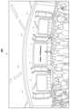
画像生成部344は、パノラマ画像からユーザの視野の範囲を抽出したVR画像を生成する。出力部346は、VR画像をヘッドマウントディスプレイ100へ出力して表示させる。図6~図16は、VR画像の例を示す。以下、図6~図16を参照して、ヘッドマウントディスプレイ100に表示されるVR画像の遷移を説明する。The
(1)コンポーネントの表示に関する動作:
図6のVR画像400は、ユーザが略正面を向いている場合にヘッドマウントディスプレイ100に表示される。情報処理装置200の位置・姿勢取得部336は、ユーザの視線方向の変化を検出し、視野制御部338および画像生成部344は、ユーザの視線方向の変化に応じて、配信サーバ312から送信されたパノラマ画像から抽出する領域を決定する。これにより、ユーザの視線方向の変化に追従したVR画像400をヘッドマウントディスプレイ100に表示させる。 (1) Component display behavior:
6 is displayed on the head mounted
図7は、コンポーネントの表示を指示する所定の操作がコントローラ202を介して入力された場合のVR画像400の例を示す。コンポーネントの表示が指示された場合、情報処理装置200の関連情報取得部332は、ライブ配信中のゲームカンファレンスに関する複数種類の関連情報を配信サーバ312またはSNSサーバ306から取得する。情報処理装置200の画像生成部344は、複数種類の関連情報を示す複数のコンポーネント402をパノラマ画像に重畳して配置したVR画像400を生成する。なお、図7は、複数のコンポーネント402が初期位置に配置された状態を示している。画像生成部344は、非選択状態のコンポーネントを、背景のオブジェクトが見えるように半透過属性に設定する。Figure 7 shows an example of a
複数のコンポーネント402は、コンポーネント402a、コンポーネント402b、コンポーネント402c、コンポーネント402dを含む。コンポーネント402aは、第2画面を表示するコンポーネントである。第2画面は、VR画像400のメインコンテンツ(コンポーネント領域の外に写るコンテンツ)とは別のコンテンツを表示可能なサブウィンドウである。関連情報取得部332は、第2画面用の画像データを配信サーバ312から取得する。画像生成部344は、コンポーネント記憶部320に記憶された第2画面用のサブウィンドウに第2画面用の画像データを設定したコンポーネント402aをVR画像400上に配置する。The
コンポーネント402bは、ヒートマップを表示するコンポーネントである。ヒートマップは、行列型の数字データの強弱を色で視覚化したグラフである。図7のコンポーネント402bでは地球儀が描かれ、当該ゲームカンファレンスの映像が配信されているユーザ数(言い換えれば配信サーバ312へのアクセス数)が多い地域が、特定の色彩やアニメーションにより強調して示される。関連情報取得部332は、ヒートマップの元データとしての行列データを配信サーバ312または管理サーバ304から取得する。画像生成部344は、コンポーネント記憶部320に記憶されたヒートマップ用のオブジェクトを、行列データに基づいて外観を設定した上で、コンポーネント402bとしてVR画像400上に配置する。
コンポーネント402cは、演者または登壇者に関する情報(以下「演者情報」とも呼ぶ。)を表示するコンポーネントである。演者情報は、演者または登壇者の写真や、経歴、プロフィールを含む。関連情報取得部332は、演者情報を配信サーバ312から取得する。画像生成部344は、演者情報を設定したサブウィンドウをコンポーネント402cとしてVR画像400上に配置する。
コンポーネント402dは、イベント(ここではゲームカンファレンス)のスケジュールを表示するコンポーネントである。関連情報取得部332は、イベントのスケジュール情報を配信サーバ312から取得する。画像生成部344は、イベントのスケジュール情報を設定したサブウィンドウをコンポーネント402dとしてVR画像400上に配置する。
図8は、コンポーネント402a(第2画面)が選択された場合のVR画像400を示している。位置・姿勢取得部336によりコントローラ202の姿勢変化が検出された場合、画像生成部344は、コントローラオブジェクト404と、そのコントローラオブジェクト404から伸びるビーム406をさらに描画したVR画像400を新たに生成して表示させる。Figure 8 shows the
コントローラオブジェクト404は、ユーザが把持するコントローラ202に対応する仮想空間内のオブジェクト(VRコンテンツ)である。画像生成部344は、コントローラ202の姿勢とコントローラオブジェクト404の姿勢を同期させ、言い換えれば、コントローラ202の姿勢変化に合わせてコントローラオブジェクト404の姿勢を変化させる。ビーム406は、コントローラオブジェクト404の奥側側面(ユーザから見て奥側側面)から垂直に照射される光ビームである。The
ユーザは、所望のコンポーネント402に対してビーム406を当て、コントローラ202の所定ボタンを押下することで、そのコンポーネント402を操作対象として選択する。また、ユーザは、或るコンポーネント402を選択状態とした場合に、上記のボタンを押し続けることで、そのコンポーネント402の選択状態を維持する。The user aims the
画像生成部344は、VR画像400内の複数のコンポーネント402のうちコントローラオブジェクト404から伸びるビーム406により選択されたコンポーネント402を選択状態としたVR画像400を新たに生成して表示させる。図8では、コンポーネント402a(第2画面)がビーム406により選択された状態になっている。画像生成部344は、選択状態のコンポーネント402を、背景のオブジェクトが見えないように非透過属性に設定する。また、画像生成部344は、選択状態のコンポーネント402のサイズを非選択状態時より拡大する。The
画像生成部344は、或るコンポーネント402が選択状態であるとき、コントローラ202に第1の操作が入力された場合、仮想空間における選択状態のコンポーネント402の位置を変更したVR画像400を新たに生成する。ここでの第1の操作は、現実世界でのコントローラ202の位置または姿勢を変える操作である。画像生成部344は、位置・姿勢取得部336により検出されたコントローラ202の位置または姿勢の変化に応じて、仮想空間における選択状態のコンポーネント402の位置または姿勢を変更する。姿勢は、ユーザの視線方向に対するコンポーネント402の角度であってもよく、鉛直方向に対するコンポーネント402の角度であってもよい。例えば、現実空間でコントローラ202が左方向に動かされた場合、仮想空間における選択状態のコンポーネント402を左方向に動かす。When a first operation is input to the
ユーザは、或るコンポーネント402を選択した状態を続けつつ(所定のボタンの押下を続けつつ)コントローラ202を動かすことにより、仮想空間において当該コンポーネント402を動かすことができる。The user can move a
画像生成部344は、或るコンポーネント402が選択状態であるとき、コントローラ202に第2の操作が入力された場合、当該コンポーネント402を非選択状態としたVR画像400であって、仮想空間の背景オブジェクト上に当該コンポーネント402を配置したVR画像400を新たに生成する。ここでの第2の操作は、当該コンポーネント402を選択状態とする場合と同じ操作である。既述したように、非選択状態のコンポーネント402は、選択状態時より小さいサイズで表示され、また、背景を透過する状態で表示される。When a second operation is input to the
画像生成部344は、或るコンポーネント402が選択状態であるとき、コントローラ202に上記第2の操作が入力された場合、コントローラオブジェクト404の姿勢により特定される背景オブジェクト上の位置にそのコンポーネント402を配置する。図8で示したように、或るコンポーネント402が選択状態であるとき、VR画像400ではビーム406が選択状態のコンポーネント402を指した状態となるが、画像生成部344は、ビーム406を伸ばした場合に背景オブジェクト(元のパノラマ画像上のオブジェクト)に達する位置にコンポーネント402を配置する。When a
図9では、コンポーネント402a(第2画面)とコンポーネント402c(演者情報)の位置が変更された後、仮想空間の背景オブジェクト(カンファレンス会場の天井等)上に貼り付けられた状態を示している。画像生成部344は、コンポーネント402を背景オブジェクト上に貼り付けたように見せるため、背景オブジェクト上にコンポーネント402の画像をマッピングしてもよい。また、画像生成部344は、上記特許文献1に記載の技術を使用して、仮想空間におけるユーザの頭部を中心とする球形の背景オブジェクト上に当該コンポーネント402を配置したVR画像400を生成してもよい。Figure 9 shows the state in which
このように実施例のエンタテインメントシステム300は、ライブ配信のメインコンテンツ(例えばゲームカンファレンス会場の様子)に関連する様々な情報をコンポーネント402を介してユーザに提供する。ヘッドマウントディスプレイ100を装着したユーザはスマートフォン等を用いた即時の情報取得が困難であるところ、コンポーネント402が即時性のある情報を提示することによりユーザの利便性を高めることができる。In this way, the entertainment system 300 of the embodiment provides the user with various information related to the main content of the live broadcast (e.g., the state of the game conference venue) via the
また、複数のコンポーネント402のそれぞれをユーザが任意の位置に移動可能であるため、コンポーネント402がライブ配信のメインコンテンツの視聴の妨げになってしまうことを回避できる。また、コンポーネント402を背景オブジェクト上に配置することで、ユーザに圧迫感や違和感を抱かせにくくなる。In addition, because the user can move each of the
画像生成部344は、或るコンポーネント402が選択状態であるとき、コントローラ202に第3の操作が入力された場合、選択状態のコンポーネント402を回動させたVR画像400を新たに生成する。実施例での第3の操作は、コントローラ202の左アナログスティックに対する操作である。When a
画像生成部344は、コントローラ202の左アナログスティックに対する複数の操作態様と、コンポーネント402の複数の回動態様との対応関係を記憶してもよい。画像生成部344は、コントローラ202の左アナログスティックに対する操作が検出された場合、選択状態のコンポーネント402を、操作態様に応じた態様で回動させたVR画像400を新たに生成して表示させる。コンポーネント402の複数の回動態様は、ピッチング、ローリング、ヨーイングのいずれか、または組み合わせであってもよい。The
画像生成部344は、コンポーネント402を回動させた後に、当該コンポーネント402に対して上記第2の操作が入力された場合、回動後のコンポーネント402の画像を仮想空間の背景オブジェクトにテクスチャマッピングして貼り付ける。このように、ユーザによるコンポーネント402の回動を可能にすることで、コンポーネント402の配置態様の自由度を一層高めることができる。When the second operation is input to the
なお、配信サーバ312から提供されるパノラマ画像には、コンポーネントの配置を禁止する位置または領域(以下「配置禁止位置」とも呼ぶ。)を示すデータが付加されてもよい。画像生成部344は、選択状態が解除されたコンポーネント402を背景オブジェクト上に配置する場合に、コントローラオブジェクト404(ビーム406)により指定された配置位置(本来配置するはずの位置)が、配置禁止位置に一致するか否か、言い換えれば、配置禁止位置が示す領域に含まれるか否かを判定してもよい。The panoramic image provided by the
画像生成部344は、配置禁止位置に不一致であれば、コントローラオブジェクト404(ビーム406)により指定された位置にコンポーネント402を配置する一方、配置禁止位置に一致する場合、上記指定された位置にコンポーネント402を配置することを抑制する。例えば、画像生成部344は、コンポーネント402の選択状態を維持しつつ、現在指定された領域にコンポーネント402を配置できないことを示すメッセージを含むVR画像400を表示させてもよい。If the position specified by the controller object 404 (beam 406) does not match a prohibited position, the
または、画像生成部344は、コントローラオブジェクト404(ビーム406)により指定された位置の近傍位置であり、かつ、配置禁止位置に該当しない位置にコンポーネント402を配置してもよい。例えば、図6に示すステージ中心領域が配置禁止位置であり、コントローラオブジェクト404(ビーム406)により指定された位置がステージ中心領域に該当する場合、画像生成部344は、ステージの周辺領域にコンポーネント402を配置してもよい。この態様によると、コンポーネントの表示により、ライブ配信のメインコンテンツの視認性が低下することを防止できる。Alternatively, the
画像生成部344は、或るコンポーネント402が選択状態である場合に、コントローラ202に入力された操作(例えば右アナログスティックの操作)に基づいて、選択状態のコンポーネント402における表示内容を更新したVR画像400を新たに生成する。言い換えれば、画像生成部344は、或るコンポーネント402が選択状態であるとき、選択状態のコンポーネント402に対する操作として予め定められた所定の操作が入力された場合、当該コンポーネント402に対する操作結果を示すように当該コンポーネント402の表示内容を更新する。When a
図10は、コンポーネント402c(演者情報)が選択された状態を示している。画像生成部344は、コントローラ202の右アナログスティックが下方向(言い換えれば後ろ方向)に倒された場合、コンポーネント402cの文章およびスクロールバー408を下方向にスクロールさせる。また、画像生成部344は、コントローラ202の右アナログスティックが上方向(言い換えれば前方向)に倒された場合、コンポーネント402cの文章およびスクロールバー408を上方向にスクロールさせる。Figure 10 shows the state in which
なお、コンポーネント402に対する操作は、文書の操作に限られない。例えば、コンポーネント402a(第2画面)が選択状態の場合、画像生成部344は、ユーザの操作に基づいて、映像の再生開始、再生停止、別の映像への切り替え等の結果をコンポーネント402aに表示させてもよい。また、ミニゲーム等のアプリケーションを表示するコンポーネント402が選択状態の場合、画像生成部344は、ユーザの操作に基づくアプリケーションの実行結果(例えばミニゲームの経過および結果)を当該コンポーネント402に表示させてもよい。Note that operations on
このようにエンタテインメントシステム300では、ユーザは、ライブ配信中のコンテンツを視聴しつつ、様々な情報やアプリケーションに対する操作をコンポーネント402を介して実行できる。これにより、ユーザの利便性を一層高めることができ、また、ライブ配信中のコンテンツを単に視聴することを超えたエンタテインメント体験をユーザへ提供できる。In this way, in the entertainment system 300, the user can view live-streamed content while performing operations on various information and applications via the
なお、図10のコンポーネント402eは、ミニブログサイトに投稿されたコメント(ツイート等)のうち、ライブ配信対象のイベントに関連するコメントを表示する。例えば、関連情報取得部332は、ミニブログサービスを提供するSNSサーバ306へ定期的にアクセスし、ライブ配信対象のイベントに関連づけられた(例えば当該イベントのハッシュタグが付与された)コメントをSNSサーバ306から取得してもよい。画像生成部344は、関連情報取得部332により新たなコメントが取得される都度、コンポーネント402eの表示内容を更新してもよい。
画像生成部344は、コントローラ202に所定の操作(ここでは所定ボタンの押下)が入力された場合に、仮想空間に配置した1または複数のコンポーネント402を一括して非表示としたVR画像400を新たに生成して表示させる。例えば、図7~図10に示すVR画像400が表示中に上記所定ボタンの押下操作が検出された場合、画像生成部344は、全てのコンポーネント402を消去したVR画像400(例えば図6のVR画像400)を表示させる。これにより、ライブ配信のメインコンテンツに集中したい場合、ユーザは、簡単な操作で1または複数のコンポーネント402を一括非表示に切り替えることができる。When a predetermined operation (here, pressing a predetermined button) is input to the
また、画像生成部344は、1または複数のコンポーネント402を一括して非表示とした後、コントローラ202に所定の操作(ここでは一括非表示の操作と同じ操作)が入力された場合、1または複数のコンポーネント402を、一括非表示にした直前の位置に配置したVR画像400を新たに生成して表示させる。このように、1または複数のコンポーネント402の一括非表示および一括再表示の機能を提供することで、ライブ配信コンテンツを視聴するユーザの利便性を一層高めることができる。Furthermore, when a predetermined operation (here, the same operation as the operation for hiding all at once) is input to the
(2)画像の共有に関する動作:
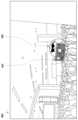
図11および図12は、仮想空間の撮像を指示する所定の操作がコントローラ202を介して入力された場合のVR画像400を示す。撮像を指示する所定の操作が入力された場合、図11に示すように、情報処理装置200の画像生成部344は、撮像装置を模した外観のオブジェクトであるカメラオブジェクト410をパノラマ画像に重畳して配置したVR画像400を生成して表示させる。カメラオブジェクト410は、仮想的なカメラとも言え、また、カメラアプリケーションを起動したスマートフォンの画面を模した外観であってもよい。カメラオブジェクト410は、仮想空間の中で撮像対象となる領域を示すファインダー画面412と、撮像対象のズームの度合いを調整するズームバー414を含む。 (2) Image sharing actions:
11 and 12 show a
画像生成部344は、コントローラオブジェクト404の上方近傍位置にカメラオブジェクト410を配置する。画像生成部344は、ユーザが把持するコントローラ202の位置または姿勢の変化に応じて、仮想空間におけるコントローラオブジェクト404の位置または姿勢を変化させるとともに、カメラオブジェクト410の位置または姿勢を変化させたVR画像400を新たに生成する。すなわち、画像生成部344は、現実空間でのコントローラ202の位置と向きと角度に同期させて、仮想空間でのコントローラオブジェクト404およびカメラオブジェクト410の位置と向きと角度を設定する。The
画像生成部344は、カメラオブジェクト410の仮想的な光軸方向(正面側)に合致する仮想空間の領域を撮像対象領域としてパノラマ画像(またはVR画像400)から抽出し、撮像対象領域の画像をファインダー画面412に設定する。図11では、ステージ上の様子が切り取られてファインダー画面412に表示されている。画像生成部344は、カメラオブジェクト410の位置または姿勢(向きおよび角度)が変化した場合、ファインダー画面412に設定する撮像対象領域を変化させる。具体的には、画像生成部344は、変化後の位置または姿勢における光軸方向の仮想空間の領域を新たな撮像対象領域として、新たな撮像対象領域の画像をファインダー画面412に設定する。The
ユーザは、ファインダー画面412が示す撮像対象領域を撮像する場合、撮像実行を指示する操作として、コントローラ202の所定ボタン(例えば○ボタン)を押下する。撮像実行操作の入力が検出されると、情報処理装置200の撮像部352は、この操作時点でファインダー画面412に表示された撮像対象領域の画像を撮像画像として撮像画像記憶部322に保存する。When the user wishes to capture an image of the imaging target area shown on the
ズームバー414は、「W」(広角)と「T」(望遠)の度合いを調整するウィジェットである。画像生成部344は、コントローラ202に入力された操作(例えば右スティックの左右方向の操作)に応じて、ズームバー414をスライドさせるとともに、ファインダー画面412における撮像対象の表示態様を、広角の態様から望遠の態様まで切り替える。The
例えば、コントローラ202の右スティックに対して右方向への操作が入力された場合、図12に示すように、画像生成部344は、デジタルズーム処理により撮像対象を拡大表示した画像をファインダー画面412に設定する。例えば、画像生成部344は、拡大前の撮像対象画像の中心部分を切り出し、その中心部分を補間処理により拡大表示した画像をファインダー画面412に設定してもよい。撮像部352は、ファインダー画面412に拡大表示された撮像対象の画像(例えばデジタルズーム処理後の画像)を撮像画像として撮像画像記憶部322に保存する。For example, when a rightward operation is input to the right stick of the
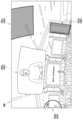
図13は、画像共有を指示する所定の操作(所定ボタンの押下等)がコントローラ202を介して入力された場合のVR画像400を示す。画像生成部344は、カメラオブジェクト410の表示中に画像共有が指示された場合、カメラオブジェクト410の内容をアルバム画面416と操作パネル418に切り替えたVR画像400を新たに生成して表示させる。画像生成部344は、撮像画像記憶部322に保存された複数の撮像画像のサムネイルをアルバム画面416に表示させる。アルバム画面416において特定の撮像画像がユーザにより選択された場合、画像生成部344は、選択された撮像画像をアルバム画面416に表示させる。Figure 13 shows a
画像生成部344は、操作パネル418に、撮像画像を登録可能な複数のSNS(図13では「A」「B」「C」の3つのSNS)のアイコンを設定する。登録対象の撮像画像を選択する操作がコントローラ202で入力され、さらに、特定のSNSアイコンを選択する操作がコントローラ202で入力された場合、登録部354は、選択された撮像画像を、選択されたSNSに対応するSNSサーバ306に登録することにより、他のユーザによる上記撮像画像の閲覧を可能にする。例えば、登録部354は、SNSサーバ306が公開する画像登録用(言い換えれば記事登録用)のAPI(Application Programming Interface)を呼び出し、上記撮像画像をSNSサーバ306へ送信してもよい。The
登録部354は、配信サーバ312から提供され、画像取得部330により取得された撮像対象情報に基づいて、仮想空間のコンテンツ(すなわち撮像対象)を説明するデータ(ここでは「撮像画像説明情報」と呼ぶ。)を自動生成する。登録部354は、撮像画像説明情報を撮像画像とともにSNSサーバ306に登録する。撮像画像説明情報(撮像対象情報)は、例えば、(1)ライブ配信対象のイベント(ゲームカンファレンス等)の名称、(2)イベントが開かれている都市名、会場名、(3)情報処理装置200等を使用してオンラインでイベントにアクセスする場合のURLを含んでもよい。The
このように実施例のエンタテインメントシステム300によると、現実のイベント会場でスマートフォン等を使用してイベントを撮影しているようなVR体験をユーザに提供できる。また、エンタテインメントシステム300によると、ユーザが撮影したイベントの画像を他者(友人等)と共有することを支援できる。また、ヘッドマウントディスプレイを装着したユーザは文字等の入力が困難であるが、撮像画像説明情報を撮像画像に自動的に付加することにより、他者に撮像画像の内容を理解させやすくなる。また、SNSにおけるいわゆる「いいね」の獲得を支援できる。さらにまた、イベントの周知にも資することができる。In this way, the entertainment system 300 of the embodiment can provide the user with a VR experience that feels like they are shooting an event at a real event venue using a smartphone or the like. The entertainment system 300 can also assist the user in sharing the images of the event that they have shot with others (friends, etc.). Although it is difficult for a user wearing a head-mounted display to input text, etc., automatically adding captured image description information to a captured image makes it easier for others to understand the contents of the captured image. It can also assist in gaining so-called "likes" on SNS. It can also contribute to publicizing the event.
(3)フレンドの表示に関する動作:
図14は、コントローラ202を介して、フレンド表示に関する所定の操作(例えばフレンドメニューの選択操作)が入力された場合に表示されるVR画像400を示す。VR画像400の表示中にフレンドメニューが選択されると、フレンド情報取得部334は、ユーザのフレンド情報を管理サーバ304から取得する。画像生成部344は、フレンド情報が示すユーザのフレンドのアバター420を並べたVR画像400を新たに生成して表示させる。 (3) Behavior related to displaying friends:
14 shows a
特定のフレンドのアバター420を選択する操作が入力された場合、画像生成部344は、操作パネル422を含むVR画像400を新たに生成して表示させる。操作パネル422は、フレンド情報取得部334により取得されたフレンド情報が示す内容であり、選択されたアバター420が示すフレンドの現在の状態を表示する。フレンドの現在の状態は、例えば、インターネット接続中か否か、および/または、ヘッドマウントディスプレイを起動中か否かを含んでもよい。When an operation to select a specific friend's
また、操作パネル422は、フレンドの状態に応じて、ライブ配信中のイベントへフレンドを招待するためのオブジェクト(リンク、ボタン等)を含む。上記オブジェクトは、例えば、フレンドの状態がインターネット接続中、かつ、ヘッドマウントディスプレイ起動中の場合、三次元画像を配信するライブ配信チャンネルを案内する内容の招待メールを送信するものであってもよい。また、上記オブジェクトは、フレンドの状態がインターネット接続中、かつ、ヘッドマウントディスプレイ未起動の場合、二次元画像を配信するライブ配信チャンネルを案内する内容の招待メールを送信するものであってもよい。The
招待メール送信用のオブジェクトを選択する操作がコントローラ202を介して入力された場合、要求部350は、招待メールの送信を指示するデータを管理サーバ304へ送信する。管理サーバ304へ送信するデータは、例えば、選択されたアバター420が示すフレンドを宛先として指定し、かつ、当該フレンドの状態に応じた内容(メールで案内するアクセス先等)を指定するものであってもよい。When an operation to select an object for sending an invitation email is input via the
図15は、招待メールを送信したフレンドが、ユーザと同じライブ配信チャンネルに接続した場合に表示されるVR画像400を示す。画像生成部344は、ユーザの近傍位置(例えば隣の座席等)に、フレンド(ここでは「参加フレンド」と呼ぶ。)のアバター420を表示させる。Figure 15 shows a
エンタテインメントシステム300では、ユーザ間のボイスチャットが可能である。参加フレンドの情報処理装置200に入力された参加フレンドの音声データは、管理サーバ304を介してユーザの情報処理装置200に送信され、ユーザの情報処理装置200は、参加フレンドの音声をスピーカーやイヤホン等から出力させる。画像生成部344は、参加フレンドの音声が出力される間、アバター420の明度を通常より高め、または、アバター420を点滅表示させる。言い換えれば、画像生成部344は、参加フレンドの音声が出力される間、音声未出力時とは異なる態様でアバター420を表示させる。The entertainment system 300 allows voice chat between users. The voice data of the participating friend input to the participating friend's
フレンド情報取得部334は、参加フレンドのヘッドマウントディスプレイ100の姿勢(またはフレンドの視線方向)を示すフレンド情報を管理サーバ304から取得する。画像生成部344は、参加フレンドの視線方向を示す姿勢オブジェクト424をアバター420に付加する。画像生成部344は、参加フレンドのヘッドマウントディスプレイ100の姿勢に一致するように姿勢オブジェクト424の向きおよび角度を設定する。これにより、イベント会場におけるフレンドの視線方向、言い換えれば、イベント会場でフレンドが見ているものをユーザに把握させやすくなり、ユーザ・フレンド間の円滑なコミュニケーションを支援することができる。The friend
(4)カメラ切替に関する動作:
図16は、コントローラ202を介してカメラ切替に関する所定の操作(例えばカメラ切替メニューの選択操作)が入力された場合に表示されるVR画像400を示している。画像生成部344は、全天球カメラ310が設置された複数のイベント会場(南ホール、西ホール等)に対応する複数の会場選択ボタン430を配置したVR画像400を表示させる。ここでは、会場が選択されるが、同じ会場に複数の全天球カメラ310が配置され、会場の変更を伴わずに、パノラマ画像を撮像する全天球カメラを変更する場合も同様の動作になる。 (4) Camera switching operations:
16 shows a
特定の会場選択ボタン430をフォーカスする操作(例えば左右への方向入力操作)が入力された場合、画像取得部330は、フォーカスされた会場選択ボタン430が示すイベント会場(「仮選択会場」とも呼ぶ。)に設置された全天球カメラ310により撮像されたパノラマ映像(もしくはその動画サムネイル)を配信サーバ312から取得する。画像生成部344は、中継画面432を表示させ、仮選択会場に設置された全天球カメラ310により撮像されたパノラマ映像(もしくはその動画サムネイル)を中継画面432に配置する。When an operation to focus on a specific venue selection button 430 (for example, a directional input operation to the left or right) is input, the
また、画像取得部330は、仮選択会場に設置された全天球カメラ310により撮像されたパノラマ映像を配信中(言い換えれば視聴中)の1人以上のユーザの情報を配信サーバ312からさらに取得する。画像生成部344は、当該パノラマ画像を視聴中のユーザの中に自装置のユーザのフレンドが存在する場合、そのフレンドを示すアバター420を中継画面432とともに表示させる。この態様により、情報処理装置200は、ライブ映像を視聴する会場またはカメラをユーザが選択することを支援できる。The
特定の会場選択ボタン430をフォーカスした状態で所定の選択操作(例えば所定ボタンの押下)が入力された場合、情報処理装置200の要求部350は、フォーカスされた会場選択ボタン430が示すイベント会場を本選択会場として認識し、本選択会場に設置された全天球カメラ310により撮像されたパノラマ画像のライブ配信を要求するデータを配信サーバ312へ送信する。これにより、ライブ配信のメインコンテンツが切り替わり、例えば、図16の中継画面432に表示された南ホールのライブ映像がVR画像400全体に表示される。When a specific selection operation (e.g., pressing a specific button) is input with a specific
以上、本発明を実施例をもとに説明した。この実施例は例示であり、各構成要素あるいは各処理プロセスの組合せにいろいろな変形例が可能なこと、またそうした変形例も本発明の範囲にあることは当業者に理解されるところである。The present invention has been described above based on examples. These examples are merely illustrative, and it will be understood by those skilled in the art that various modifications are possible in the combination of each component or each treatment process, and that such modifications are also within the scope of the present invention.
上記実施例では言及していないが、コンポーネント402の種類、および/または、コンポーネント402に表示される内容を、イベントの進行に伴って更新してもよく、言い換えれば、ライブ配信のメインコンテンツの変化に伴って更新してもよい。例えば、配信サーバ312は、ライブ配信対象のイベントの進行に応じて、例えば、予め定められたスケジュールに応じて、コンポーネント402の種類および/または表示内容を更新することを指示するデータ(「コンポーネント更新指示」と呼ぶ。)を情報処理装置200へ送信してもよい。コンポーネント更新指示は、更新後のコンポーネント402の種類および/または表示内容の指定を含んでもよい。Although not mentioned in the above embodiment, the type of
情報処理装置200の画像取得部330は、配信サーバ312から送信されたコンポーネント更新指示を受信してもよい。情報処理装置200の画像生成部344は、コンポーネント更新指示にしたがって、VR画像に配置する少なくとも1つのコンポーネント402の種類または内容を、仮想空間に表示されるイベント(ゲームカンファレンス等)の進行に応じて更新してもよい。The
情報処理装置200の画像生成部344は、コンポーネント更新指示により指定された種類のコンポーネント402をVR画像400に表示させてもよい。また、関連情報取得部332は、コンポーネント更新指示により指定された関連情報を配信サーバ312、SNSサーバ306等から新たに取得してもよい。画像生成部344は、コンポーネント更新指示により指定された関連情報を、更新後のコンポーネント402に表示させてもよい。The
この構成によると、例えば、ライブ中継会場において複数の商品が順次紹介される場合に、紹介される商品の情報をコンポーネント402に表示させ、紹介される商品が変わることにあわせてコンポーネント402の表示内容を切り替えることができる。また、ステージ上の話者のプロフィールをコンポーネント402に表示させ、話者が変わることにあわせてコンポーネント402の表示内容を切り替えることができる。According to this configuration, for example, when multiple products are introduced in sequence at a live broadcast venue, information about the products being introduced can be displayed in
また、上記実施例では言及していないが、図15のように参加フレンドのアバター420を表示させ、かつ、参加フレンドのフレンド(以下「FOAF」とも呼ぶ。)が同じライブ配信を視聴中の場合、画像生成部344は、参加フレンドのアバター420とは別にFOAFのアバターを表示させてもよい。これにより、ユーザは参加フレンドからFOAFを紹介してもらうこともでき、ユーザのフレンド拡大を支援できる。Although not mentioned in the above embodiment, when the
具体的な構成として、情報処理装置200のフレンド情報取得部334は、FOAFが同じライブ配信を視聴中の場合、そのことを示す情報を管理サーバ304から取得してもよい。画像生成部344は、FOAFが同じライブ配信を視聴中であることが管理サーバ304から通知されると、ユーザから見て参加フレンドのアバター420より奥の位置にFOAFのアバターを表示させてもよい。画像生成部344は、FOAFのアバターを、存在は識別可能だが、個人を識別不可能な態様で表示させてもよい。例えば、画像生成部344は、FOAFのアバターをぼかした態様で表示させてもよく、FOAFのアバターとして中身のない円だけを示すオブジェクトを表示させてもよい。As a specific configuration, when a FOAF is watching the same live broadcast, the friend
また、上記実施例では、ヘッドマウントディスプレイ100に、ライブ配信されたコンテンツに基づくVR画像を表示したが、実施例に記載の技術は、様々なVR画像を表示する場合に適用可能である。例えば、ヘッドマウントディスプレイ100に表示されるVR画像は、予め撮影された360度のパノラマ静止画またはパノラマ動画の他、ゲーム空間のような人工的なパノラマ画像に基づくものであってもよい。また、情報処理装置200と接続されたサーバによるアプリケーション実行結果に基づくVR画像、または、情報処理装置200によるアプリケーション実行結果に基づくVR画像をヘッドマウントディスプレイ100に表示する場合にも実施例に記載の技術は有用である。すなわち、情報処理装置200の画像取得部330は、情報処理装置200またはサーバによるアプリケーション処理結果としての仮想空間の画像を取得してもよい。In the above embodiment, a VR image based on live-streamed content is displayed on the head-mounted
上述した実施例および変形例の任意の組み合わせもまた本開示の実施の形態として有用である。組み合わせによって生じる新たな実施の形態は、組み合わされる実施例および変形例それぞれの効果をあわせもつ。また、請求項に記載の各構成要件が果たすべき機能は、実施例および変形例において示された各構成要素の単体もしくはそれらの連携によって実現されることも当業者には理解されるところである。Any combination of the above-mentioned examples and modifications is also useful as an embodiment of the present disclosure. A new embodiment resulting from the combination will have the combined effects of each of the examples and modifications. It will also be understood by those skilled in the art that the functions to be performed by each of the constituent elements recited in the claims can be realized by each of the components shown in the examples and modifications alone or in combination with each other.
100 ヘッドマウントディスプレイ、 200 情報処理装置、 202 コントローラ、 236 出力部、 300 エンタテインメントシステム、 330 画像取得部、 332 関連情報取得部、 344 画像生成部、 346 出力部、 352 撮像部、 354 登録部。100 Head mounted display, 200 Information processing device, 202 Controller, 236 Output unit, 300 Entertainment system, 330 Image acquisition unit, 332 Related information acquisition unit, 344 Image generation unit, 346 Output unit, 352 Imaging unit, 354 Registration unit.
Claims (6)
Translated fromJapanese前記仮想空間における撮像対象領域を示す撮像装置オブジェクトと、前記仮想空間に関する複数種類の情報を表示する複数のコンポーネントと、前記コンポーネントを操作するためのオブジェクトと、を前記仮想空間に配置した表示用画像を生成する画像生成部と、
前記表示用画像を前記ヘッドマウントディスプレイに表示させる出力部と、
撮像部と、
を備え、
前記画像生成部は、ユーザが把持するコントローラの位置または姿勢の変化に応じて、前記仮想空間における前記撮像装置オブジェクトの位置または姿勢を変化させた表示用画像であり、かつ、前記撮像装置オブジェクトが示す撮像対象領域を変化させた表示用画像を生成し、
前記コンポーネントを操作するためのオブジェクトは、前記ユーザが把持するコントローラを示すコントローラオブジェクトであり、
前記画像生成部は、前記ユーザが把持するコントローラの位置または姿勢の変化に応じて、前記コントローラオブジェクトの位置または姿勢を変化させた表示用画像であり、かつ、前記撮像装置オブジェクトの位置または姿勢を変化させた表示用画像を生成し、
前記撮像部は、前記撮像装置オブジェクトが示す撮像対象領域の画像を保存することを特徴とする情報処理装置。 an acquisition unit that acquires an image of a virtual space to be displayed on a head mounted display;
an image generating unit that generates a display image in which an imaging device object indicating an imaging target area in the virtual space, a plurality of components that display a plurality of types of information related to the virtual space, and an object for operating the components are arranged in the virtual space;
an output unit that displays the display image on the head mounted display;
An imaging unit;
Equipped with
the image generation unit generates a display image in which a position or an attitude of the imaging device object in the virtual space is changed in response to a change in a position or an attitude of a controller held by a user, and in which an imaging target area indicated by the imaging device object is changed;
the object for operating the component is a controller object indicating a controller held by the user,
the image generation unit generates a display image in which a position or an attitude of the controller object is changed in response to a change in a position or an attitude of the controller held by the user, and in which a position or an attitude of the imaging device object is changed;
The information processing apparatus according to claim 1, wherein the imaging unit stores an image of an imaging target area indicated by the imaging device object.
前記撮像部は、前記撮像装置オブジェクトにおいて拡大表示された撮像対象の画像を保存することを特徴とする請求項1に記載の情報処理装置。 the image generation unit, in response to an operation input to the controller, enlarges and displays an imaging target in the virtual space indicated by the imaging device object;
The information processing apparatus accordingto claim 1 , wherein the imaging unit stores an image of the imaging target that is enlarged and displayed in the imaging device object.
前記仮想空間における撮像対象領域を示す撮像装置オブジェクトと、前記仮想空間に関する複数種類の情報を表示する複数のコンポーネントと、前記コンポーネントを操作するためのオブジェクトと、を前記仮想空間に配置した表示用画像を生成するステップと、
前記表示用画像を前記ヘッドマウントディスプレイに表示させるステップと、
をコンピュータが実行し、
前記生成するステップは、ユーザが把持するコントローラの位置または姿勢の変化に応じて、前記仮想空間における前記撮像装置オブジェクトの位置または姿勢を変化させた表示用画像であり、かつ、前記撮像装置オブジェクトが示す撮像対象領域を変化させた表示用画像を生成し、
前記コンポーネントを操作するためのオブジェクトは、前記ユーザが把持するコントローラを示すコントローラオブジェクトであり、
前記生成するステップは、前記ユーザが把持するコントローラの位置または姿勢の変化に応じて、前記コントローラオブジェクトの位置または姿勢を変化させた表示用画像であり、かつ、前記撮像装置オブジェクトの位置または姿勢を変化させた表示用画像を生成し、
前記撮像装置オブジェクトが示す撮像対象領域の画像を保存するステップを前記コンピュータがさらに実行することを特徴とする情報処理方法。 acquiring an image of a virtual space to be displayed on a head mounted display;
generating a display image in which an imaging device object indicating an imaging target area in the virtual space, a plurality of components displaying a plurality of types of information related to the virtual space, and objects for operating the components are arranged in the virtual space;
displaying the display image on the head mounted display;
The computer executes
the generating step generates a display image in which a position or an attitude of the imaging device object in the virtual space is changed in response to a change in a position or an attitude of a controller held by a user, and a display image in which an imaging target area indicated by the imaging device object is changed;
the object for operating the component is a controller object indicating a controller held by the user,
the generating step generates a display image in which a position or a posture of the controller object is changed in response to a change in a position or a posture of the controller held by the user, and the display image in which a position or a posture of the imaging device object is changed is generated;
The information processing method, further comprising the step of storing an image of an imaging target area indicated by the imaging device object.
前記仮想空間における撮像対象領域を示す撮像装置オブジェクトと、前記仮想空間に関する複数種類の情報を表示する複数のコンポーネントと、前記コンポーネントを操作するためのオブジェクトと、を前記仮想空間に配置した表示用画像を生成する機能と、
前記表示用画像を前記ヘッドマウントディスプレイに表示させる機能と、
をコンピュータに実現させ、
前記生成する機能は、ユーザが把持するコントローラの位置または姿勢の変化に応じて、前記仮想空間における前記撮像装置オブジェクトの位置または姿勢を変化させた表示用画像であり、かつ、前記撮像装置オブジェクトが示す撮像対象領域を変化させた表示用画像を生成し、
前記コンポーネントを操作するためのオブジェクトは、前記ユーザが把持するコントローラを示すコントローラオブジェクトであり、
前記生成する機能は、前記ユーザが把持するコントローラの位置または姿勢の変化に応じて、前記コントローラオブジェクトの位置または姿勢を変化させた表示用画像であり、かつ、前記撮像装置オブジェクトの位置または姿勢を変化させた表示用画像を生成し、
前記撮像装置オブジェクトが示す撮像対象領域の画像を保存する機能を前記コンピュータにさらに実現させるためのコンピュータプログラム。 A function to acquire images of the virtual space to be displayed on the head-mounted display;
a function of generating a display image in which an imaging device object indicating an imaging target area in the virtual space, a plurality of components for displaying a plurality of types of information related to the virtual space, and objects for operating the components are arranged in the virtual space;
A function of displaying the display image on the head mounted display;
This is realized on a computer.
the generating function generates a display image in which a position or an attitude of the imaging device object in the virtual space is changed in response to a change in a position or an attitude of a controller held by a user, and in which an imaging target area indicated by the imaging device object is changed;
the object for operating the component is a controller object indicating a controller held by the user,
the generating function is a display image in which a position or a posture of the controller object is changed in response to a change in a position or a posture of the controller held by the user, and a display image in which a position or a posture of the imaging device object is changed is generated;
A computer program for causing the computer to further realize a function of saving an image of an imaging target area indicated by the imaging device object.
Priority Applications (2)
| Application Number | Priority Date | Filing Date | Title |
|---|---|---|---|
| JP2022040053AJP7498209B2 (en) | 2018-02-15 | 2022-03-15 | Information processing device, information processing method, and computer program |
| JP2024011850AJP7589374B2 (en) | 2018-02-15 | 2024-01-30 | Information processing device, information processing method, and computer program |
Applications Claiming Priority (2)
| Application Number | Priority Date | Filing Date | Title |
|---|---|---|---|
| JP2018024754AJP7042644B2 (en) | 2018-02-15 | 2018-02-15 | Information processing equipment, image generation method and computer program |
| JP2022040053AJP7498209B2 (en) | 2018-02-15 | 2022-03-15 | Information processing device, information processing method, and computer program |
Related Parent Applications (1)
| Application Number | Title | Priority Date | Filing Date |
|---|---|---|---|
| JP2018024754ADivisionJP7042644B2 (en) | 2018-02-15 | 2018-02-15 | Information processing equipment, image generation method and computer program |
Related Child Applications (1)
| Application Number | Title | Priority Date | Filing Date |
|---|---|---|---|
| JP2024011850ADivisionJP7589374B2 (en) | 2018-02-15 | 2024-01-30 | Information processing device, information processing method, and computer program |
Publications (2)
| Publication Number | Publication Date |
|---|---|
| JP2022079503A JP2022079503A (en) | 2022-05-26 |
| JP7498209B2true JP7498209B2 (en) | 2024-06-11 |
Family
ID=67540491
Family Applications (3)
| Application Number | Title | Priority Date | Filing Date |
|---|---|---|---|
| JP2018024754AActiveJP7042644B2 (en) | 2018-02-15 | 2018-02-15 | Information processing equipment, image generation method and computer program |
| JP2022040053AActiveJP7498209B2 (en) | 2018-02-15 | 2022-03-15 | Information processing device, information processing method, and computer program |
| JP2024011850AActiveJP7589374B2 (en) | 2018-02-15 | 2024-01-30 | Information processing device, information processing method, and computer program |
Family Applications Before (1)
| Application Number | Title | Priority Date | Filing Date |
|---|---|---|---|
| JP2018024754AActiveJP7042644B2 (en) | 2018-02-15 | 2018-02-15 | Information processing equipment, image generation method and computer program |
Family Applications After (1)
| Application Number | Title | Priority Date | Filing Date |
|---|---|---|---|
| JP2024011850AActiveJP7589374B2 (en) | 2018-02-15 | 2024-01-30 | Information processing device, information processing method, and computer program |
Country Status (2)
| Country | Link |
|---|---|
| US (2) | US20190250699A1 (en) |
| JP (3) | JP7042644B2 (en) |
Families Citing this family (21)
| Publication number | Priority date | Publication date | Assignee | Title |
|---|---|---|---|---|
| WO2020095784A1 (en)* | 2018-11-06 | 2020-05-14 | 日本電気株式会社 | Display control device, display control method, and nontemporary computer-readable medium in which program is stored |
| IL265495B (en)* | 2019-03-19 | 2022-09-01 | Rober Ohrenstein | Method for travel authorization |
| US11599238B2 (en)* | 2019-04-02 | 2023-03-07 | Vyaire Medical, Inc. | System and method for generating a virtual reality interface for displaying patient health data |
| US20200349749A1 (en)* | 2019-05-03 | 2020-11-05 | XRSpace CO., LTD. | Virtual reality equipment and method for controlling thereof |
| JP6688518B1 (en)* | 2019-09-26 | 2020-04-28 | 株式会社アクトキューブ | Method for determining coordinate axis and surface identification method in three-dimensional space |
| CN110896495A (en)* | 2019-11-19 | 2020-03-20 | 北京字节跳动网络技术有限公司 | View adjustment method and device for target device, electronic device and medium |
| CN111420402B (en)* | 2020-03-18 | 2021-05-14 | 腾讯科技(深圳)有限公司 | Virtual environment picture display method, device, terminal and storage medium |
| JP7522576B2 (en)* | 2020-04-08 | 2024-07-25 | 株式会社Nttドコモ | Control device and program |
| CN111933062B (en)* | 2020-08-10 | 2021-11-19 | 成都网传文化传播有限公司 | Scenic spot intelligent sharing explanation system based on VR |
| WO2022264846A1 (en)* | 2021-06-15 | 2022-12-22 | 至 石井 | Virtual travel system, virtual gathering system, and communication terminal |
| CN117546458A (en)* | 2021-06-30 | 2024-02-09 | 索尼集团公司 | Information processing device, information processing method, and program |
| JP2023011262A (en)* | 2021-07-12 | 2023-01-24 | トヨタ自動車株式会社 | Virtual reality simulator and virtual reality simulation program |
| WO2023286222A1 (en)* | 2021-07-14 | 2023-01-19 | ガンホー・オンライン・エンターテイメント株式会社 | Processing device, program, and method |
| JP7089815B1 (en) | 2021-11-25 | 2022-06-23 | 滋啓 内田 | server |
| JP7178752B1 (en) | 2021-11-25 | 2022-11-28 | 滋啓 内田 | Performance video display program and performance video distribution system |
| JP7392957B2 (en)* | 2022-03-29 | 2023-12-06 | グリー株式会社 | Computer programs, methods and server devices |
| CN114697755A (en)* | 2022-03-31 | 2022-07-01 | 北京百度网讯科技有限公司 | Virtual scene information interaction method, apparatus, device and storage medium |
| CN117197400A (en)* | 2022-05-31 | 2023-12-08 | 北京字跳网络技术有限公司 | Information interaction method, device, electronic equipment and storage medium |
| JP7378851B2 (en)* | 2022-06-06 | 2023-11-14 | 滋啓 内田 | display device |
| JP2024004019A (en)* | 2022-06-28 | 2024-01-16 | 株式会社Nttドコモ | Control device and control system |
| CN117435040A (en)* | 2022-07-14 | 2024-01-23 | 北京字跳网络技术有限公司 | Information interaction methods, devices, electronic equipment and storage media |
Citations (3)
| Publication number | Priority date | Publication date | Assignee | Title |
|---|---|---|---|---|
| JP2008067875A (en) | 2006-09-13 | 2008-03-27 | Namco Bandai Games Inc | PROGRAM, INFORMATION STORAGE MEDIUM, AND GAME DEVICE |
| US20090077030A1 (en) | 2007-09-13 | 2009-03-19 | Hon Hai Precision Industry Co., Ltd. | Camera unit and method for inserting comments to digital pictures automatically |
| CN105915766A (en) | 2016-06-07 | 2016-08-31 | 腾讯科技(深圳)有限公司 | Control method and device based on virtual reality |
Family Cites Families (17)
| Publication number | Priority date | Publication date | Assignee | Title |
|---|---|---|---|---|
| JP3105131B2 (en)* | 1993-07-02 | 2000-10-30 | 松下電器産業株式会社 | Virtual experience-based virtual experience device |
| JP4636908B2 (en)* | 2005-03-14 | 2011-02-23 | キヤノン株式会社 | Image processing apparatus and image processing method |
| US20080158242A1 (en)* | 2007-01-03 | 2008-07-03 | St Jacques Kimberly | Virtual image preservation |
| JP2009145883A (en)* | 2007-11-20 | 2009-07-02 | Rissho Univ | Learning system, storage medium, and learning method |
| US20120113223A1 (en)* | 2010-11-05 | 2012-05-10 | Microsoft Corporation | User Interaction in Augmented Reality |
| US9213405B2 (en)* | 2010-12-16 | 2015-12-15 | Microsoft Technology Licensing, Llc | Comprehension and intent-based content for augmented reality displays |
| EP2812089B1 (en)* | 2012-02-06 | 2019-04-10 | Sony Interactive Entertainment Europe Limited | Book object for augmented reality |
| EP3001407A4 (en)* | 2013-05-21 | 2017-01-25 | Sony Corporation | Display control device, display control method, and recording medium |
| WO2017037962A1 (en)* | 2015-08-28 | 2017-03-09 | 株式会社タカラトミー | Information processing device provided with head-mounted display |
| JP6684559B2 (en)* | 2015-09-16 | 2020-04-22 | 株式会社バンダイナムコエンターテインメント | Program and image generation device |
| JP6518582B2 (en)* | 2015-12-21 | 2019-05-22 | 株式会社ソニー・インタラクティブエンタテインメント | Information processing apparatus and operation reception method |
| US10546013B2 (en)* | 2016-07-18 | 2020-01-28 | Joshua Fagans | File management system facilitating the organization of content by using visualizations of the organizational state augmented by a configurable workflow |
| US10489978B2 (en) | 2016-07-26 | 2019-11-26 | Rouslan Lyubomirov DIMITROV | System and method for displaying computer-based content in a virtual or augmented environment |
| JP6093473B1 (en)* | 2016-08-19 | 2017-03-08 | 株式会社コロプラ | Information processing method and program for causing computer to execute information processing method |
| US20180095635A1 (en) | 2016-10-04 | 2018-04-05 | Facebook, Inc. | Controls and Interfaces for User Interactions in Virtual Spaces |
| US10564800B2 (en)* | 2017-02-23 | 2020-02-18 | Spatialand Inc. | Method and apparatus for tool selection and operation in a computer-generated environment |
| JP6470796B2 (en)* | 2017-06-12 | 2019-02-13 | 株式会社コロプラ | Information processing method, program, and computer |
- 2018
- 2018-02-15JPJP2018024754Apatent/JP7042644B2/enactiveActive
- 2019
- 2019-02-01USUS16/264,986patent/US20190250699A1/ennot_activeAbandoned
- 2022
- 2022-03-15JPJP2022040053Apatent/JP7498209B2/enactiveActive
- 2022-05-26USUS17/825,907patent/US20220283632A1/ennot_activeAbandoned
- 2024
- 2024-01-30JPJP2024011850Apatent/JP7589374B2/enactiveActive
Patent Citations (3)
| Publication number | Priority date | Publication date | Assignee | Title |
|---|---|---|---|---|
| JP2008067875A (en) | 2006-09-13 | 2008-03-27 | Namco Bandai Games Inc | PROGRAM, INFORMATION STORAGE MEDIUM, AND GAME DEVICE |
| US20090077030A1 (en) | 2007-09-13 | 2009-03-19 | Hon Hai Precision Industry Co., Ltd. | Camera unit and method for inserting comments to digital pictures automatically |
| CN105915766A (en) | 2016-06-07 | 2016-08-31 | 腾讯科技(深圳)有限公司 | Control method and device based on virtual reality |
Also Published As
| Publication number | Publication date |
|---|---|
| JP2019139672A (en) | 2019-08-22 |
| JP2022079503A (en) | 2022-05-26 |
| JP7042644B2 (en) | 2022-03-28 |
| JP2024050721A (en) | 2024-04-10 |
| US20190250699A1 (en) | 2019-08-15 |
| JP7589374B2 (en) | 2024-11-25 |
| US20220283632A1 (en) | 2022-09-08 |
Similar Documents
| Publication | Publication Date | Title |
|---|---|---|
| JP7498209B2 (en) | Information processing device, information processing method, and computer program | |
| US11563779B2 (en) | Multiuser asymmetric immersive teleconferencing | |
| US12079942B2 (en) | Augmented and virtual reality | |
| JP2019139673A (en) | Information processing apparatus, information processing method, and computer program | |
| US10127632B1 (en) | Display and update of panoramic image montages | |
| JP6581666B2 (en) | Pinch and hold gesture navigation on head mounted display | |
| US20180321798A1 (en) | Information processing apparatus and operation reception method | |
| US20230368464A1 (en) | Information processing system, information processing method, and information processing program | |
| US12001645B2 (en) | Methods, systems, and media for presenting media content previews | |
| US20230405475A1 (en) | Shooting method, apparatus, device and medium based on virtual reality space | |
| US20190250805A1 (en) | Systems and methods for managing collaboration options that are available for virtual reality and augmented reality users | |
| JP2023019088A (en) | Image processing device, image processing method, and program | |
| CN119383447A (en) | Image processing device, image processing method, system, computer program product, storage medium and computer-implemented method | |
| US20240022688A1 (en) | Multiuser teleconferencing with spotlight feature | |
| JP7742612B1 (en) | Information processing system, information processing method, and computer program | |
| US20230316670A1 (en) | Volumetric immersion system & method | |
| WO2023248832A1 (en) | Remote viewing system and on-site imaging system | |
| WO2025094267A1 (en) | Image processing device, image processing method, and data structure of 3d scene information for display |
Legal Events
| Date | Code | Title | Description |
|---|---|---|---|
| A621 | Written request for application examination | Free format text:JAPANESE INTERMEDIATE CODE: A621 Effective date:20220315 | |
| A131 | Notification of reasons for refusal | Free format text:JAPANESE INTERMEDIATE CODE: A131 Effective date:20230606 | |
| A521 | Request for written amendment filed | Free format text:JAPANESE INTERMEDIATE CODE: A523 Effective date:20230803 | |
| A02 | Decision of refusal | Free format text:JAPANESE INTERMEDIATE CODE: A02 Effective date:20231121 | |
| A521 | Request for written amendment filed | Free format text:JAPANESE INTERMEDIATE CODE: A523 Effective date:20240130 | |
| A911 | Transfer to examiner for re-examination before appeal (zenchi) | Free format text:JAPANESE INTERMEDIATE CODE: A911 Effective date:20240207 | |
| TRDD | Decision of grant or rejection written | ||
| A01 | Written decision to grant a patent or to grant a registration (utility model) | Free format text:JAPANESE INTERMEDIATE CODE: A01 Effective date:20240528 | |
| A61 | First payment of annual fees (during grant procedure) | Free format text:JAPANESE INTERMEDIATE CODE: A61 Effective date:20240530 | |
| R150 | Certificate of patent or registration of utility model | Ref document number:7498209 Country of ref document:JP Free format text:JAPANESE INTERMEDIATE CODE: R150 |