JP7494701B2 - Control device, control method, and street light - Google Patents
Control device, control method, and street lightDownload PDFInfo
- Publication number
- JP7494701B2 JP7494701B2JP2020178453AJP2020178453AJP7494701B2JP 7494701 B2JP7494701 B2JP 7494701B2JP 2020178453 AJP2020178453 AJP 2020178453AJP 2020178453 AJP2020178453 AJP 2020178453AJP 7494701 B2JP7494701 B2JP 7494701B2
- Authority
- JP
- Japan
- Prior art keywords
- terminal device
- control unit
- image
- control
- lighting
- Prior art date
- Legal status (The legal status is an assumption and is not a legal conclusion. Google has not performed a legal analysis and makes no representation as to the accuracy of the status listed.)
- Active
Links
Images


Classifications
- H—ELECTRICITY
- H05—ELECTRIC TECHNIQUES NOT OTHERWISE PROVIDED FOR
- H05B—ELECTRIC HEATING; ELECTRIC LIGHT SOURCES NOT OTHERWISE PROVIDED FOR; CIRCUIT ARRANGEMENTS FOR ELECTRIC LIGHT SOURCES, IN GENERAL
- H05B47/00—Circuit arrangements for operating light sources in general, i.e. where the type of light source is not relevant
- H05B47/10—Controlling the light source
- H05B47/105—Controlling the light source in response to determined parameters
- H05B47/115—Controlling the light source in response to determined parameters by determining the presence or movement of objects or living beings
- H05B47/125—Controlling the light source in response to determined parameters by determining the presence or movement of objects or living beings by using cameras
- H—ELECTRICITY
- H04—ELECTRIC COMMUNICATION TECHNIQUE
- H04L—TRANSMISSION OF DIGITAL INFORMATION, e.g. TELEGRAPHIC COMMUNICATION
- H04L67/00—Network arrangements or protocols for supporting network services or applications
- H04L67/01—Protocols
- H04L67/12—Protocols specially adapted for proprietary or special-purpose networking environments, e.g. medical networks, sensor networks, networks in vehicles or remote metering networks
- H—ELECTRICITY
- H04—ELECTRIC COMMUNICATION TECHNIQUE
- H04N—PICTORIAL COMMUNICATION, e.g. TELEVISION
- H04N23/00—Cameras or camera modules comprising electronic image sensors; Control thereof
- H04N23/70—Circuitry for compensating brightness variation in the scene
- H04N23/71—Circuitry for evaluating the brightness variation
- G—PHYSICS
- G06—COMPUTING OR CALCULATING; COUNTING
- G06T—IMAGE DATA PROCESSING OR GENERATION, IN GENERAL
- G06T7/00—Image analysis
- G06T7/0002—Inspection of images, e.g. flaw detection
- G—PHYSICS
- G06—COMPUTING OR CALCULATING; COUNTING
- G06T—IMAGE DATA PROCESSING OR GENERATION, IN GENERAL
- G06T7/00—Image analysis
- G06T7/10—Segmentation; Edge detection
- G06T7/11—Region-based segmentation
- H—ELECTRICITY
- H04—ELECTRIC COMMUNICATION TECHNIQUE
- H04N—PICTORIAL COMMUNICATION, e.g. TELEVISION
- H04N23/00—Cameras or camera modules comprising electronic image sensors; Control thereof
- H04N23/70—Circuitry for compensating brightness variation in the scene
- H04N23/74—Circuitry for compensating brightness variation in the scene by influencing the scene brightness using illuminating means
- H—ELECTRICITY
- H04—ELECTRIC COMMUNICATION TECHNIQUE
- H04W—WIRELESS COMMUNICATION NETWORKS
- H04W4/00—Services specially adapted for wireless communication networks; Facilities therefor
- H04W4/02—Services making use of location information
- H04W4/025—Services making use of location information using location based information parameters
- H04W4/026—Services making use of location information using location based information parameters using orientation information, e.g. compass
- H—ELECTRICITY
- H04—ELECTRIC COMMUNICATION TECHNIQUE
- H04W—WIRELESS COMMUNICATION NETWORKS
- H04W4/00—Services specially adapted for wireless communication networks; Facilities therefor
- H04W4/02—Services making use of location information
- H04W4/029—Location-based management or tracking services
- H—ELECTRICITY
- H05—ELECTRIC TECHNIQUES NOT OTHERWISE PROVIDED FOR
- H05B—ELECTRIC HEATING; ELECTRIC LIGHT SOURCES NOT OTHERWISE PROVIDED FOR; CIRCUIT ARRANGEMENTS FOR ELECTRIC LIGHT SOURCES, IN GENERAL
- H05B47/00—Circuit arrangements for operating light sources in general, i.e. where the type of light source is not relevant
- H05B47/10—Controlling the light source
- H05B47/105—Controlling the light source in response to determined parameters
- H05B47/11—Controlling the light source in response to determined parameters by determining the brightness or colour temperature of ambient light
- H—ELECTRICITY
- H05—ELECTRIC TECHNIQUES NOT OTHERWISE PROVIDED FOR
- H05B—ELECTRIC HEATING; ELECTRIC LIGHT SOURCES NOT OTHERWISE PROVIDED FOR; CIRCUIT ARRANGEMENTS FOR ELECTRIC LIGHT SOURCES, IN GENERAL
- H05B47/00—Circuit arrangements for operating light sources in general, i.e. where the type of light source is not relevant
- H05B47/10—Controlling the light source
- H05B47/175—Controlling the light source by remote control
- H05B47/19—Controlling the light source by remote control via wireless transmission
- G—PHYSICS
- G06—COMPUTING OR CALCULATING; COUNTING
- G06T—IMAGE DATA PROCESSING OR GENERATION, IN GENERAL
- G06T2200/00—Indexing scheme for image data processing or generation, in general
- G06T2200/28—Indexing scheme for image data processing or generation, in general involving image processing hardware
- G—PHYSICS
- G06—COMPUTING OR CALCULATING; COUNTING
- G06T—IMAGE DATA PROCESSING OR GENERATION, IN GENERAL
- G06T2207/00—Indexing scheme for image analysis or image enhancement
- G06T2207/30—Subject of image; Context of image processing
- G06T2207/30168—Image quality inspection
- G—PHYSICS
- G06—COMPUTING OR CALCULATING; COUNTING
- G06T—IMAGE DATA PROCESSING OR GENERATION, IN GENERAL
- G06T2207/00—Indexing scheme for image analysis or image enhancement
- G06T2207/30—Subject of image; Context of image processing
- G06T2207/30181—Earth observation
- G06T2207/30184—Infrastructure
- G—PHYSICS
- G06—COMPUTING OR CALCULATING; COUNTING
- G06T—IMAGE DATA PROCESSING OR GENERATION, IN GENERAL
- G06T2207/00—Indexing scheme for image analysis or image enhancement
- G06T2207/30—Subject of image; Context of image processing
- G06T2207/30232—Surveillance
- Y—GENERAL TAGGING OF NEW TECHNOLOGICAL DEVELOPMENTS; GENERAL TAGGING OF CROSS-SECTIONAL TECHNOLOGIES SPANNING OVER SEVERAL SECTIONS OF THE IPC; TECHNICAL SUBJECTS COVERED BY FORMER USPC CROSS-REFERENCE ART COLLECTIONS [XRACs] AND DIGESTS
- Y02—TECHNOLOGIES OR APPLICATIONS FOR MITIGATION OR ADAPTATION AGAINST CLIMATE CHANGE
- Y02B—CLIMATE CHANGE MITIGATION TECHNOLOGIES RELATED TO BUILDINGS, e.g. HOUSING, HOUSE APPLIANCES OR RELATED END-USER APPLICATIONS
- Y02B20/00—Energy efficient lighting technologies, e.g. halogen lamps or gas discharge lamps
- Y02B20/40—Control techniques providing energy savings, e.g. smart controller or presence detection
Landscapes
- Engineering & Computer Science (AREA)
- Signal Processing (AREA)
- Computer Networks & Wireless Communication (AREA)
- Theoretical Computer Science (AREA)
- Computer Vision & Pattern Recognition (AREA)
- Physics & Mathematics (AREA)
- General Physics & Mathematics (AREA)
- Multimedia (AREA)
- Quality & Reliability (AREA)
- Health & Medical Sciences (AREA)
- Computing Systems (AREA)
- General Health & Medical Sciences (AREA)
- Medical Informatics (AREA)
- Circuit Arrangement For Electric Light Sources In General (AREA)
- Selective Calling Equipment (AREA)
- Telephonic Communication Services (AREA)
Description
Translated fromJapanese本開示は、制御装置、制御方法、及び街灯に関する。The present disclosure relates to a control device, a control method, and a street light.
従来、対象物の位置に照明装置の照射位置を追従させることで、暗い場所での撮影を可能にする技術が知られている。例えば、特許文献1には、非接触センサを用いて対象物の位置を検出し、当該対象物の位置にスポットライトの照射位置を追従させ、当該照射位置にカメラの撮像範囲を一致させる技術が記載されている。Conventionally, there is known a technology that enables shooting in a dark place by tracking the illumination position of a lighting device to the position of the object. For example, Patent Document 1 describes a technology that detects the position of the object using a non-contact sensor, tracks the illumination position of a spotlight to the position of the object, and matches the imaging range of the camera to the illumination position.
しかしながら、従来の技術では、対象物を撮影するために専用の照明装置を用いる必要があった。However, conventional technology requires the use of dedicated lighting equipment to capture images of objects.
本開示の目的は、専用の照明装置を用いずに、暗い場所でも対象物を撮影しやすくすることである。The purpose of this disclosure is to make it easier to photograph objects in dark places without using a dedicated lighting device.
本開示に係る制御装置は、
端末装置によって撮影された対象物の画像を取得し、
取得した前記画像に応じて、前記端末装置の周囲に設けられた少なくとも1つの街灯を制御する制御部を備える。 The control device according to the present disclosure includes:
Acquire an image of the object photographed by a terminal device;
The terminal device includes a control unit that controls at least one street light provided around the terminal device in response to the acquired image.
本開示に係る制御方法は、
端末装置によって撮影された対象物の画像を取得することと、
取得した前記画像に応じて、前記端末装置の周囲に設けられた少なくとも1つの街灯を制御することと
を含む。 The control method according to the present disclosure includes:
Obtaining an image of an object photographed by a terminal device;
and controlling at least one street light provided around the terminal device in response to the acquired image.
本開示に係る街灯は、
少なくとも1つの光源部と、
制御装置と通信する通信部と、
前記通信部を介して前記制御装置から指示を取得し、取得した前記指示に従って前記光源部の光量を変化させる制御部と、
を備える。 The street light according to the present disclosure comprises:
At least one light source unit;
A communication unit that communicates with the control device;
a control unit that receives an instruction from the control device via the communication unit and changes the light amount of the light source unit in accordance with the received instruction;
Equipped with.
本実施形態によれば、専用の照明装置を用いずとも、暗い場所でも対象物を撮影しやすくすることができる。This embodiment makes it easier to photograph objects even in dark places without using a dedicated lighting device.
以下、本開示の実施形態について、図を参照して説明する。各図中、同一又は相当する部分には、同一符号を付している。本実施形態の説明において、同一又は相当する部分については、説明を適宜省略又は簡略化する。Embodiments of the present disclosure will be described below with reference to the drawings. In each drawing, identical or corresponding parts are given the same reference numerals. In the description of this embodiment, descriptions of identical or corresponding parts will be omitted or simplified as appropriate.
(第1実施形態)
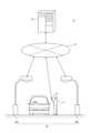
図1を参照して、本実施形態に係るシステム10の構成を説明する。First Embodiment
The configuration of a
本実施形態に係るシステム10は、制御装置20と、端末装置30と、1つ以上の照明装置40とを備える。図1では説明の簡便のため、2つの照明装置40を図示しているが、照明装置40の数はこれに限られず、自由に定められてよい。The
以下の説明において、照明装置40Aから照明装置40Fを特に区別しない場合、照明装置40Aから照明装置40Fを総称して照明装置40と呼ぶ。In the following description, unless there is a particular distinction between
制御装置20は、ネットワーク50を介して端末装置30、及び照明装置40と通信可能である。The
ネットワーク50は、インターネット、少なくとも1つのWAN、少なくとも1つのMAN、又はこれらの組み合わせを含む。「WAN」は、wide area networkの略語である。「MAN」は、metropolitan area networkの略語である。ネットワーク50は、少なくとも1つの無線ネットワーク、少なくとも1つの光ネットワーク、又はこれらの組み合わせを含んでもよい。無線ネットワークは、例えば、アドホックネットワーク、セルラーネットワーク、無線LAN、衛星通信ネットワーク、又は地上マイクロ波ネットワークである。「LAN」は、local area networkの略語である。Network 50 includes the Internet, at least one WAN, at least one MAN, or a combination thereof. "WAN" is an abbreviation for wide area network. "MAN" is an abbreviation for metropolitan area network. Network 50 may include at least one wireless network, at least one optical network, or a combination thereof. A wireless network may be, for example, an ad-hoc network, a cellular network, a wireless LAN, a satellite communication network, or a terrestrial microwave network. "LAN" is an abbreviation for local area network.
制御装置20は、データセンタなどの施設に設置される。制御装置20は、例えば、クラウドコンピューティングシステム又はその他のコンピューティングシステムに属するサーバである。The
端末装置30は、ユーザ11によって使用される。端末装置30は、例えば、携帯電話機、スマートフォン、ウェアラブル機器、若しくはタブレットなどのモバイル機器、又はPCである。「PC」は、personal computerの略語である。The
照明装置40は、屋外又は屋内の一定の領域を照射可能な装置である。照明装置40は道路に設けられた街灯を含む。照明装置40は、公共施設又は店舗等の建物、看板、信号機、電柱等に備え付けられていてもよい。照明装置40は、照明装置40の付近の道路、広場又は駐車場等に光を照射できる。照明装置40は、例えば街灯であるがこれに限られない。例えば、撮影専用に設けられた照明以外の任意の照明が、照明装置40として採用可能である。The
図1を参照して、本実施形態の概要を説明する。An overview of this embodiment will be explained with reference to Figure 1.
図1に示すシステム10において、制御装置20は、端末装置30よって撮影された対象物の画像を取得し、取得した画像に応じて、端末装置30の周囲に設けられた少なくとも1つの照明装置40を制御する制御部21を備える。In the
「対象物」は、車両についたキズを含む。車両は、例えばカーシェアリングサービスで利用される車両を含む。「端末装置30の周囲」とは、端末装置30の前方、後方、側方等が含まれる。端末装置30の周囲とは、より具体的には、端末装置30を使用するユーザ11が立っている場所の周囲をいう。"Object" includes scratches on a vehicle. Vehicles include, for example, vehicles used in car sharing services. "Surroundings of
図2を参照して、本実施形態に係る制御装置20の構成を説明する。制御装置20は、制御部21と、記憶部22と、通信部23と、入力部24と、出力部25とを備える。The configuration of the
制御部21には、少なくとも1つのプロセッサ、少なくとも1つの専用回路、又はこれらの組み合わせが含まれる。プロセッサは、CPU若しくはGPU等の汎用プロセッサ、又は特定の処理に特化した専用プロセッサである。「CPU」は、central processing unitの略語である。「GPU」は、graphics processing unitの略語である。専用回路は、例えば、FPGA又はASICである。「FPGA」は、field-programmable gate arrayの略語である。「ASIC」は、application specific integrated circuitの略語である。制御部21は、制御装置20の各部を制御しながら、制御装置20の動作に関わる処理を実行する。The
制御部21は、端末装置30から、通信部23を介して画像を受信する。このようにして制御部21は画像を取得する。制御部21は、取得した画像の明るさが基準値未満であるかどうかを判断する。画像の明るさとは、具体的には、取得した画像に含まれる各画素の輝度値の平均値をいう。画像の明るさとは、これに限られず、例えば、取得した画像のコントラスト比の高さ等であってもよい。基準値とは、撮影する対象物が認識できる程度の値をいい、例えば130の輝度値をいう。基準値はこれに限定されず、自由に設定されてよい。制御部21は、対象物として車両のキズを認識できる。制御部21は、周知の画像解析技術を用いて取得した画像を解析し、対象物を認識してよい。制御部21は、例えば、機械学習によって生成された条件に基づいて対象物を認識してもよい。The
取得した画像の明るさが基準値未満であると判断した場合、制御部21は、端末装置30に、端末装置30の位置を示す位置情報の送信を要求する。制御部21は、通信部23を介して、当該要求を端末装置30に送信する。If it is determined that the brightness of the acquired image is less than the reference value, the
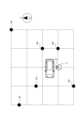
制御部21は、端末装置30から、通信部23を介して位置情報を受信する。このようにして制御部21は位置情報を取得する。制御部21は、記憶部22に格納した地図情報を参照する。地図情報には、照明装置40の位置が予め登録されている。制御部21は、地図情報に登録されている複数の照明装置40の中から、端末装置30の位置から基準距離以内に設けられている照明装置40を選択する。基準距離とは、例えば10mの距離をいう。基準距離はこれに限定されず、自由に設定されてよい。図3は、端末装置30及び照明装置40の位置の例を示す図である。図3では、ユーザ11が端末装置30を使用して、被写体である車両のキズを撮影している。図3において、照明装置40Aから40Fの位置は黒丸で示される。照明装置40Aから40Fのうち、端末装置30の位置から基準距離以内に設けられている照明装置40は、照明装置40Aから照明装置40Dである。よって制御部21はまず、照明装置40Aから照明装置40Dを選択する。このようにして制御部21は、複数の照明装置40のうち、端末装置30の周囲に設けられた少なくとも1つの照明装置40を選択する。The
位置情報には、端末装置30の位置を示す情報の他、端末装置30が向いている方向の情報も含まれる。制御部21は、端末装置30が向いている方向に基づいて、照明装置40をさらに絞り込んで選択する。端末装置30が向いている方向とは、具体的には端末装置30の撮影部37が向いている方角である。制御部21は、逆光とならないよう、端末装置30の位置を基点として、端末装置30が向いている方向と反対側の方向に設けられている照明装置40を選択する。図3を参照すると、端末装置30が向いている方向は北の方向である。この場合、制御部21は、照明装置40Aから照明装置40Dのうち、端末装置30が向いている方向と反対側に設けられている照明装置40A及び照明装置40Bを選択する。端末装置30が向いている方向に基づいて選択される照明装置40の条件はこれに限られず、自由に定められてよい。The location information includes information indicating the position of the
制御部21は、選択した照明装置40に、光源部43の点灯の状態を検出した結果を示す点灯情報の送信を要求する。制御部21は、通信部23を介して、当該要求を照明装置40に送信する。制御部21は、照明装置40から送信された点灯情報を、通信部23を介して受信する。このようにして制御部21は点灯情報を取得する。The
制御部21は、取得した点灯情報に応じて、選択した照明装置40に指示する動作を決定する。制御部21は、点灯情報が消灯中を示す場合に、光源部43を点灯させる動作を決定する。また、制御部21は、点灯情報が点灯中を示す場合に、点灯中の発光素子の数を増加した状態で光源部43を点灯させる動作を決定してもよい。制御部21が決定する動作の種類はこれらに限られず、自由に設定されてよい。The
選択した照明装置40が複数ある場合、制御部21は、照明装置40のそれぞれについて異なる動作を決定してよい。例えば、制御部21は、照明装置40Aと照明装置40Bとで異なる数の発光素子を点灯させた状態で、それぞれの光源部43を点灯させる動作を決定してもよい。When
制御部21は決定した動作の指示を、選択した照明装置40に送信する。制御部21は、通信部23を介して動作の指示を送信する。照明装置40は動作の指示を受信し、指示に従って動作する。このようにして制御部21は照明装置40の光量を増加させる。The
制御部21は、動作の指示を送信したあと、端末装置30に再度撮影を行うよう通知を送信する。制御部21は、通信部23を介して通知を端末装置30へ送信する。通知を受信した端末装置30は、再度、被写体の撮影を行う。端末装置30の制御部31は、通信部33を介して通知を受信すると、再度撮影を行うよう撮影部37を制御してもよい。また、端末装置30の制御部31は、受信した通知を、出力部35を介してユーザ11に対し表示してもよい。これにより、ユーザ11が表示を認識し、端末装置30を操作して再度の撮影を行うことができる。After sending the instruction to perform the operation, the
制御部21は、端末装置30から取得した画像の明るさが基準値以上であると判断するまで、端末装置30からの画像の取得と照明装置40の制御とを繰り返し実行する。繰り返しにおいて、制御部21は、選択した照明装置40に指示する動作を前回と異なる動作に決定できる。例えば、前回決定された動作が、一定数の発光素子を点灯させた状態で光源部43を点灯させる動作であったとする。この場合制御部21は、繰り返しにおいて、当該数よりも多い数、又は当該数よりも少ない数の発光素子を点灯させた状態で光源部43を点灯させる動作を決定してよい。これにより、照明装置40の光量を様々なパターンに変化させることができる。The
このように制御装置20が照明装置40を制御することで、端末装置30が様々な明るさの下で撮影することが可能となる。In this way, the
記憶部22には、少なくとも1つの半導体メモリ、少なくとも1つの磁気メモリ、少なくとも1つの光メモリ、又はこれらのうち少なくとも2種類の組み合わせが含まれる。半導体メモリは、例えば、RAM又はROMである。「RAM」は、random access memoryの略語である。「ROM」は、read only memoryの略語である。RAMは、例えば、SRAM又はDRAMである。「SRAM」は、static random access memoryの略語である。「DRAM」は、dynamic random access memoryの略語である。ROMは、例えば、EEPROMである。「EEPROM」は、electrically erasable programmable read only memoryの略語である。記憶部22は、例えば、主記憶装置、補助記憶装置、又はキャッシュメモリとして機能する。記憶部22には、制御装置20の動作に用いられる情報と、制御装置20の動作によって得られた情報とが記憶される。記憶部22は、システムプログラム、アプリケーションプログラム、及び地図情報を記憶する。地図情報には、照明装置40の位置が予め登録されている。地図情報は、記憶部22に予め格納される代わりに、インターネット上のGISなど、外部のシステムに蓄積されていてもよい。「GIS」は、geographic information systemの略語である。The
通信部23には、少なくとも1つの通信用インタフェースが含まれる。通信用インタフェースは、例えば、LANインタフェースである。通信部23は、制御装置20の動作に用いられる情報を受信し、また制御装置20の動作によって得られる情報を送信する。The
入力部24には、少なくとも1つの入力用インタフェースが含まれる。入力用インタフェースは、例えば、物理キー、静電容量キー、ポインティングデバイス、ディスプレイと一体的に設けられたタッチスクリーン、又はマイクである。入力部24は、制御装置20の動作に用いられる情報を入力する操作を受け付ける。入力部24は、制御装置20に備えられる代わりに、外部の入力機器として制御装置20に接続されてもよい。接続方式としては、例えば、USB、HDMI(登録商標)、又はBluetooth(登録商標)等の任意の方式を用いることができる。「USB」は、Universal Serial Busの略語である。「HDMI(登録商標)」は、High-Definition Multimedia Interfaceの略語である。The
出力部25には、少なくとも1つの出力用インタフェースが含まれる。出力用インタフェースは、例えば、ディスプレイ又はスピーカである。ディスプレイは、例えば、LCD又は有機ELディスプレイである。「LCD」は、liquid crystal displayの略語である。「EL」は、electro luminescenceの略語である。出力部25は、制御装置20の動作によって得られる情報を出力する。出力部25は、制御装置20に備えられる代わりに、外部の出力機器として制御装置20に接続されてもよい。接続方式としては、例えば、USB、HDMI(登録商標)、又はBluetooth(登録商標)等の任意の方式を用いることができる。The
制御装置20の機能は、本実施形態に係る制御プログラムを、制御部21に相当するプロセッサで実行することにより実現される。すなわち、制御装置20の機能は、ソフトウェアにより実現される。制御プログラムは、制御装置20の動作をコンピュータに実行させることで、コンピュータを制御装置20として機能させる。すなわち、コンピュータは、制御プログラムに従って制御装置20の動作を実行することにより制御装置20として機能する。The functions of the
プログラムは、非一時的なコンピュータ読取り可能な媒体に記録しておくことができる。非一時的なコンピュータ読取り可能な媒体は、例えば、磁気記録装置、光ディスク、光磁気記録媒体、又は半導体メモリである。プログラムの流通は、例えば、プログラムを記録したDVD又はCD-ROM等の可搬型記録媒体を販売、譲渡、又は貸与することによって行う。「DVD」は、digital versatile discの略語である。「CD-ROM」は、compactdisc read only memoryの略語である。プログラムをサーバのストレージに格納しておき、サーバから他のコンピュータにプログラムを転送することにより、プログラムを流通させてもよい。プログラムをプログラムプロダクトとして提供してもよい。The program may be recorded on a non-transitory computer-readable medium. The non-transitory computer-readable medium may be, for example, a magnetic recording device, an optical disk, a magneto-optical recording medium, or a semiconductor memory. The program may be distributed, for example, by selling, transferring, or lending a portable recording medium such as a DVD or CD-ROM on which the program is recorded. "DVD" is an abbreviation for digital versatile disc. "CD-ROM" is an abbreviation for compact disc read only memory. The program may be distributed by storing the program in the storage of a server and transferring the program from the server to another computer. The program may be provided as a program product.
コンピュータは、例えば、可搬型記録媒体に記録されたプログラム又はサーバから転送されたプログラムを、一旦、主記憶装置に格納する。そして、コンピュータは、主記憶装置に格納されたプログラムをプロセッサで読み取り、読み取ったプログラムに従った処理をプロセッサで実行する。コンピュータは、可搬型記録媒体から直接プログラムを読み取り、プログラムに従った処理を実行してもよい。コンピュータは、コンピュータにサーバからプログラムが転送される度に、逐次、受け取ったプログラムに従った処理を実行してもよい。サーバからコンピュータへのプログラムの転送は行わず、実行指示及び結果取得のみによって機能を実現する、いわゆるASP型のサービスによって処理を実行してもよい。「ASP」は、application service providerの略語である。プログラムには、電子計算機による処理の用に供する情報であってプログラムに準ずるものが含まれる。例えば、コンピュータに対する直接の指令ではないがコンピュータの処理を規定する性質を有するデータは、「プログラムに準ずるもの」に該当する。The computer temporarily stores in the main storage device, for example, a program recorded on a portable recording medium or a program transferred from a server. The computer then reads the program stored in the main storage device with a processor and executes processing according to the read program with the processor. The computer may read the program directly from the portable recording medium and execute processing according to the program. The computer may execute processing according to the received program each time a program is transferred to the computer from the server. Processing may be executed by a so-called ASP-type service that does not transfer a program from the server to the computer and achieves functions only by issuing execution instructions and obtaining results. "ASP" is an abbreviation for application service provider. Programs include information used for processing by a computer and equivalent to a program. For example, data that is not a direct command to a computer but has properties that define computer processing falls under " equivalent to a program".
制御装置20の一部又は全ての機能が、制御部21に相当する専用回路により実現されてもよい。すなわち、制御装置20の一部又は全ての機能が、ハードウェアにより実現されてもよい。Some or all of the functions of the
図2を参照して、本実施形態に係る端末装置30の構成を説明する。端末装置30は、制御部31と、記憶部32と、通信部33と、入力部34と、出力部35と、測位部36と、撮影部37とを備える。The configuration of the
制御部31には、少なくとも1つのプロセッサ、少なくとも1つの専用回路、又はこれらの組み合わせが含まれる。プロセッサは、CPU若しくはGPU等の汎用プロセッサ、又は特定の処理に特化した専用プロセッサである。専用回路は、例えば、FPGA又はASICである。制御部31は、端末装置30の各部を制御しながら、端末装置30の動作に関わる処理を実行する。The
記憶部32には、少なくとも1つの半導体メモリ、少なくとも1つの磁気メモリ、少なくとも1つの光メモリ、又はこれらのうち少なくとも2種類の組み合わせが含まれる。半導体メモリは、例えば、RAM又はROMである。RAMは、例えば、SRAM又はDRAMである。ROMは、例えば、EEPROMである。記憶部32は、例えば、主記憶装置、補助記憶装置、又はキャッシュメモリとして機能する。記憶部32には、端末装置30の動作に用いられる情報と端末装置30の動作によって得られた情報とが記憶される。The
通信部33には、少なくとも1つの通信用インタフェースが含まれる。通信用インタフェースは、例えば、LTE、4G規格、若しくは5G規格等の移動通信規格に対応したインタフェース、Bluetooth(登録商標)等の近距離無線通信に対応したインタフェース、又はLANインタフェースである。「LTE」は、Long Term Evolutionの略語である。「4G」は、4th generationの略語である。「5G」は、5th generationの略語である。通信部33は、端末装置30の動作に用いられる情報を受信し、また端末装置30の動作によって得られる情報を送信する。The
入力部34には、少なくとも1つの入力用インタフェースが含まれる。入力用インタフェースは、例えば、物理キー、静電容量キー、ポインティングデバイス、ディスプレイと一体的に設けられたタッチスクリーン、又はマイクである。入力部34は、端末装置30の動作に用いられる情報を入力する操作を受け付ける。入力部34は、端末装置30に備えられる代わりに、外部の入力機器として端末装置30に接続されてもよい。接続方式としては、例えば、USB、HDMI(登録商標)、又はBluetooth(登録商標)等の任意の方式を用いることができる。The
出力部35には、少なくとも1つの出力用インタフェースが含まれる。出力用インタフェースは、例えば、ディスプレイ、スピーカ、又は振動モータある。ディスプレイは、例えば、LCD又は有機ELディスプレイである。出力部35は、端末装置30の動作によって得られる情報を出力する。出力部35は、端末装置30に備えられる代わりに、外部の出力機器として端末装置30に接続されてもよい。接続方式としては、例えば、USB、HDMI(登録商標)、又はBluetooth(登録商標)等の任意の方式を用いることができる。The
測位部36には、少なくとも1つのGNSS受信機が含まれる。「GNSS」は、global navigation satellite systemの略語である。GNSSには、例えば、GPS、QZSS、BeiDou、GLONASS、及びGalileoの少なくともいずれかが含まれる。「GPS」は、Global Positioning Systemの略語である。「QZSS」は、Quasi-Zenith Satellite Systemの略語である。QZSSの衛星は、準天頂衛星と呼ばれる。「GLONASS」は、Global Navigation Satellite Systemの略語である。測位部36は、地磁気センサ及び加速度センサを含む。測位部36は、端末装置30の位置と、端末装置30が向いている方向とを検出することができる。端末装置30が向いている方向とは、具体的には撮影部37が向いている方角である。測位部36が検出した、端末装置30の位置と端末装置30が向いている方向とを示す情報は、位置情報として制御部31に取得される。位置情報は、制御部31によって制御装置20に送信される。位置情報の送信は、本実施形態では、制御装置20からの要求に応じて行われるが、これに限られず、常時行われてもよい。The
撮影部37は、端末装置30の周囲を撮影するカメラである。撮影部37は、ユーザ11の操作によって静止画又は動画を取得可能である。撮影部37は取得した画像を制御部31に出力できる。撮影部37は例えば、出力部35と反対側の面に設けられる。The photographing
端末装置30の機能は、本実施形態に係る端末プログラムを、制御部31に相当するプロセッサで実行することにより実現される。すなわち、端末装置30の機能は、ソフトウェアにより実現される。端末プログラムは、端末装置30の動作をコンピュータに実行させることで、コンピュータを端末装置30として機能させる。すなわち、コンピュータは、端末プログラムに従って端末装置30の動作を実行することにより端末装置30として機能する。The functions of the
端末装置30の一部又は全ての機能が、制御部31に相当する専用回路により実現されてもよい。すなわち、端末装置30の一部又は全ての機能が、ハードウェアにより実現されてもよい。Some or all of the functions of the
図1及び図2を参照して、本実施形態に係る照明装置40の構成を説明する。照明装置40は、図2に示すように、制御部41と、通信部42と、光源部43とを備える。The configuration of the
制御部41には、少なくとも1つのプロセッサ、少なくとも1つの専用回路、又はこれらの組み合わせが含まれる。プロセッサは、CPU若しくはGPU等の汎用プロセッサ、又は特定の処理に特化した専用プロセッサである。専用回路は、例えば、FPGA又はASICである。制御部41は、照明装置40の各部を制御しながら、照明装置40の動作に関わる処理を実行する。The
制御部41は、光源部43の点灯の状態を検出し、検出した結果を点灯情報として取得する。点灯情報とは、照明装置40の光源部43が点灯中であるかどうかについての情報を含む。点灯情報はさらに、点灯中の発光素子の数を示す情報を含んでもよい。制御部41は、点灯情報を、通信部42を介して制御装置20に送信する。点灯情報の送信は制御装置20の要求に応じて行われる。これに限られず、点灯情報の送信は常時行われてもよい。The
制御部41は、通信部42を介して、動作の指示を制御装置20から受信する。制御部41は、受信した指示に従って光源部43を制御する。制御部41は、受信した指示に従って、光源部43を点灯又は消灯させることができる。制御部41は、受信した指示に従って、点灯中の発光素子の数を増加した状態で光源部43を点灯させることができる。The
通信部42には、少なくとも1つの通信用インタフェースが含まれる。通信用インタフェースは、例えば、LTE、4G規格、若しくは5G規格等の移動通信規格に対応したインタフェースである。通信部42は、照明装置40の動作に用いられる情報を受信し、また照明装置40の動作によって得られる情報を送信する。The
光源部43は、筐体内に1つ以上の発光素子を備える。発光素子は、LED又は有機EL等を含む。「LED」は、Light Emitting Diodeの略語である。光源部43は、制御部41の制御によって点灯又は消灯させられる。点灯中の発光素子の数は、制御部41の制御によって増加又は減少させられてもよい。このようにして照明装置40の光量が変化させられる。また、光源部43が発光素子を覆う蓋を備え、制御部41の制御によって当該蓋が開閉させられることにより、照明装置40の光量が変化させられてもよい。The
図3、図4A、及び図4Bを参照して、本実施形態に係るシステム10の動作を説明する。この動作は、本実施形態に係る制御方法に相当する。本例では、ユーザ11が端末装置30を用いて、車両の車体についたキズを撮影しているとする。本例において、照明装置40Aは制御部41A、通信部42A、及び光源部43Aを備える。本例において、照明装置40Bは制御部41B、通信部42B、及び光源部43Bを備える。本例では、簡便のため図4Bにおいて照明装置40は一台のみ示す。図4A及び図4Bは、本実施形態に係るシステム10全体の処理フローを示す。The operation of the
図4AのステップS101において、端末装置30は、被写体の撮影を行う。本例では、端末装置30の撮影部37が、被写体としての車両についたキズを撮影する。端末装置30の制御部31は、撮影部47が撮影した画像を取得する。In step S101 of FIG. 4A, the
ステップS102において、端末装置30は、撮影した被写体の画像を制御装置20に送信する。本例では、端末装置30の制御部31は、撮影部37から取得した画像を、通信部33を介して制御装置20に送信する。In step S102, the
ステップS103において、制御装置20は、画像を端末装置30から受信する。本例では、制御装置20の制御部21は、通信部23を介して、画像を端末装置30から受信する。このようにして制御装置20は画像を取得する。In step S103, the
ステップS104において、制御部21は、取得した画像の明るさが基準値未満であるかどうかを判断する。制御部21が、取得した画像の明るさが基準値以上であると判断した場合、システム10の動作は終了する。制御部21が、取得した画像の明るさが基準値未満であると判断した場合、システム10の動作はステップS105に進む。本例では、制御部21は、取得した画像の各画素の輝度値の平均値が、基準値の130未満であるかどうかを判断する。本例では、取得した画像の各画素の輝度値の平均値は100である。よって制御部21の処理はステップS105に進む。In step S104, the
ステップS105において、制御部21は、端末装置30に、位置情報の送信を要求する。本例では、制御部21は、通信部23を介して、端末装置30に位置情報の送信の要求を送信する。In step S105, the
ステップS106において、端末装置30は、位置情報の要求を受信する。本例では、端末装置30の制御部31は、通信部33を介して要求を受信する。In step S106, the
ステップS107において、端末装置30は、位置情報を取得する。本例では、端末装置30の測位部36が、端末装置30の位置と、端末装置30の撮影部37が向いている方向とを検出する。本例では、端末装置30が向いている方向は北の方向である。端末装置30の制御部31は、測位部36が検出した端末装置30の位置と端末装置30が向いている方向とを示す情報を位置情報として取得する。In step S107, the
ステップS108において、端末装置30は、取得した位置情報を制御装置20に送信する。本例では、端末装置30の制御部31は、測位部36から取得した位置情報を、通信部33を介して制御装置20に送信する。In step S108, the
ステップS109において、制御装置20は、位置情報を端末装置30から受信する。本例では、制御装置20の制御部21は、通信部23を介して、位置情報を端末装置30から受信する。このようにして制御装置20は位置情報を取得する。In step S109, the
ステップS110において、制御部21は、ステップS109で取得した端末装置30の位置情報から、端末装置30の位置から基準距離以内に設けられている照明装置40を選択する。本例では、制御部21はまず、記憶部22に格納した地図情報を参照して、地図情報に登録されている複数の照明装置40の中から、端末装置30の位置から基準距離の10m以内に設けられている照明装置40を選択する。図3を参照すると、黒丸で示す照明装置40Aから40Fのうち、端末装置30の位置から基準距離以内に設けられている照明装置40は、照明装置40Aから照明装置40Dである。制御部21は、照明装置40Aから照明装置40Dを選択する。In step S110, the
ステップS111において、制御部21は、位置情報に含まれる、端末装置30の向いている方向に基づいて照明装置40をさらに絞り込んで選択する。端末装置30が向いている方向に基づいて選択される照明装置40の条件は、自由に定められてよい。本例では、制御部21は、逆光とならないよう、端末装置30の位置を基点として、端末装置30の向いている方向と反対側に設けられている照明装置40を選択する。図3を参照すると、端末装置30が向いている方向は北の方向である。制御部21は、当該方向と反対側に設けられている照明装置40A及び照明装置40Bを選択する。In step S111, the
ステップS112において、制御部21は、選択した照明装置40に、点灯情報の送信を要求する。本例では、制御部21は、通信部23を介して、照明装置40A及び照明装置40Bに当該要求を送信する。In step S112, the
ステップS113において、照明装置40は、点灯情報の要求を受信する。本例では、照明装置40Aの制御部41Aが、通信部42Aを介して要求を受信する。また、照明装置40Bの制御部41Bが、通信部42Bを介して要求を受信する。In step S113, the
ステップS114において、照明装置40は、点灯情報を取得する。本例では、照明装置40Aの制御部41Aが光源部43Aの点灯の状態を、照明装置40Bの制御部41Bが光源部43Bの点灯の状態を、それぞれ検出する。本例では、検出された点灯の状態は、光源部43A及び光源部43Bのいずれも、一定数の発光素子を点灯させた状態で点灯中であるとする。制御部41A及び制御部41Bのそれぞれは、検出した結果を点灯情報として取得する。In step S114, the
ステップS115において、照明装置40は、点灯情報を制御装置20に送信する。本例では、照明装置40Aの制御部41Aが、通信部42Aを介して点灯情報を制御装置20に送信する。また、照明装置40Bの制御部41Bが、通信部42Bを介して点灯情報を制御装置20に送信する。In step S115, the
ステップS116において、制御装置20は点灯情報を照明装置40から受信する。本例では、制御装置20の制御部21は、通信部23を介して、点灯情報を照明装置40A及び照明装置40Bから受信する。このようにして制御装置20は点灯情報を取得する。In step S116, the
ステップS117において、制御部21は、選択した照明装置40に指示する動作を決定する。制御部21は、取得した点灯情報が消灯中を示す場合に、照明装置40の光源部43を点灯させる動作を決定する。制御部21は、点灯情報が点灯中を示す場合に、点灯中の発光素子の数を増加した状態で光源部43を点灯させる動作を決定する。制御部21が決定する動作の種類はこれらに限られず、自由に設定されてよい。本例では、制御部21は、照明装置40Aの光源部43A、及び照明装置40Bの光源部43Bを、点灯中の発光素子の数を増加させた状態で点灯させる動作を決定する。In step S117, the
ステップS118において、制御部21は、ステップS117で決定した動作の指示を、選択した照明装置40に送信する。本例では、制御部21は、通信部23を介して、動作の指示を照明装置40A及び照明装置40Bに送信する。このようにして、制御部21は照明装置40を制御する。In step S118, the
ステップS119において、照明装置40は、動作の指示を制御装置20から受信する。本例では、照明装置40Aの制御部41Aが、通信部42Aを介して動作の指示を受信する。また、照明装置40Bの制御部41Bが、通信部42Bを介して動作の指示を受信する。In step S119, the
ステップS120において、照明装置40は、ステップS119で受信した指示に従って動作する。本例では、照明装置40Aの制御部41Aは、点灯中の発光素子の数を増加させた状態で光源部43Aを点灯させる。照明装置40Bの制御部41Bも、点灯中の発光素子の数を増加させた状態で光源部43Bを点灯させる。In step S120, the
ステップS121において、制御装置20は、端末装置30に再度撮影を行うよう通知を送信する。本例では、制御装置20の制御部21は、通信部23を介して、通知を端末装置30へ送信する。In step S121, the
ステップS122において、端末装置30は制御装置20から通知を受信する。そして端末装置30の動作は、ステップS101に戻る。すなわち、システム10全体の動作がステップS101に戻る。ステップS101において、端末装置30は再度、被写体の撮影を行う。本例では、端末装置30の制御部31が通信部33を介して通知を受信する。制御部31は、再度被写体を撮影するよう、端末装置30の撮影部37を制御する。In step S122, the
以上の通り、ステップS101からステップS122の動作が、ステップS104で制御部21の判断により終了するまで繰り返される。繰り返しにおいて、ステップS117で制御部21が決定する動作は、前回と異なる動作に決定されてよい。例えば、前回決定された動作が、一定数の発光素子を点灯させた状態で光源部43A及び光源部43Bを点灯させる動作であったとする。この場合、制御部21は、光源部43Aについては当該数よりも多い数の発光素子を点灯させた状態で点灯させ、光源部43Bについては当該数よりも少ない数の発光素子を点灯させた状態で点灯させる動作を決定してよい。これにより、照明装置40の光量を様々なパターンに変化させることができる。As described above, the operations from step S101 to step S122 are repeated until the operations are terminated by the
上述のように、本実施形態に係る制御装置20は、端末装置30によって撮影された対象物の画像を取得し、取得した画像に応じて、端末装置30の周囲に設けられた少なくとも1つの照明装置40を制御する制御部21を備える。As described above, the
制御部21は、端末装置30から取得した画像に応じて照明装置40を制御する。端末装置30は、周囲に設けられた照明装置40が制御された後、より明るい環境下で再度対象物の撮影を行うことができる。よって、専用の照明装置を用いずとも、暗い場所でも対象物を撮影しやすくすることができる。The
上述のように、制御部21は、画像の明るさが基準値未満であるとき、照明装置40の光量を変化させることで照明装置40を制御する。As described above, when the brightness of the image is less than the reference value, the
制御部21は、予め設定した基準値に基づいて、取得した画像の明るさを精度よく判断できる。制御部21は、判断の結果に応じて照明装置40に指示する動作を決定する。制御部21は、照明装置40の光量を増加又は減少させる動作を決定できる。また、複数の照明装置40を選択している場合、制御部21は、ある照明装置40の光量をさらに増加させる一方、他の照明装置40の光量は減少させる動作を決定し、柔軟に照明装置40を制御し得る。これにより、端末装置30は、照明装置40が制御された後、より適切な明るさの環境下で再度撮影を行い得る。よって、専用の照明装置を用いずとも、暗い場所でも対象物を撮影しやすくすることができる。The
上述のように、制御部21は、照明装置40の光源部43の光量を増加させることで照明装置40の光量を変化させる。As described above, the
制御部21は、照明装置40の光源部43の光量を増加させる動作を決定できる。照明装置40は、動作の指示を受信し、指示に従って光源部43の光量を増加させる。これにより、端末装置30は、照明装置40が制御された後、より明るい環境下で再度撮影を行い得る。よって、専用の照明装置を用いずとも、暗い場所でも対象物を撮影しやすくすることができる。The
上述のように、制御装置20は、端末装置30と通信する通信部23をさらに備える。制御部21は、画像を端末装置30から通信部23を介して取得する。As described above, the
制御部21は、通信部23を介して、遠く離れた位置にある端末装置30からも画像を取得できる。制御部21は、取得した画像の明るさに応じて照明装置40を制御することができる。よって、専用の照明装置を用いずとも、暗い場所でも対象物を撮影しやすくすることができる。The
上述のように、制御部21は、通信部23を介して端末装置30の位置を示す位置情報を取得し、位置情報に基づいて、複数の照明装置40のうち、端末装置30の周囲に設けられた少なくとも1つの照明装置40を選択する。As described above, the
制御部21は、複数の照明装置40の中から、端末装置30の位置により近い位置にある照明装置40を選択できる。これにより、端末装置30は、より明るい環境下で再度撮影を行うことができる。よって、専用の照明装置を用いずとも、暗い場所でも対象物を撮影しやすくすることができる。The
上述のように、制御装置20において、位置情報は、端末装置30が向いている方向の情報を含む。As described above, in the
制御部21は、端末装置30が向いている方向に基づいて、端末装置30の周囲の照明装置40を選択することができる。制御部21は、端末装置30が向いている方向を考慮して、より適切な照明装置40を選択することができる。よって、専用の照明装置を用いずとも、暗い場所でも対象物を撮影しやすくすることができる。The
上述のように、制御部21は、端末装置30の位置から基準距離以内に設けられた照明装置40を選択し、選択した照明装置40を制御する。As described above, the
制御部21は、予め設定した基準距離に基づいて照明装置40を選択する。基準距離は、照明装置40が少ない地域では長く、照明装置40が多い地域では短くする等、柔軟に設定できる。基準距離を設定することで、照明装置40を効率よく選択できる。よって、専用の照明装置を用いずとも、暗い場所でも対象物を撮影しやすくすることができる。The
上述のように、制御部21は、画像の明るさが基準値未満であるかどうかについての判断を行う。制御部21は、当該判断において、画像の明るさが基準値以上であると判断するまで、対象物の画像の取得及び画像に応じた照明装置40の制御を繰り返し実行する。As described above, the
制御部21は、端末装置30が取得した画像が適切な明るさとなるまで、照明装置40の光量を変化させ続けることができる。これにより、端末装置30が様々な明るさの下で再度撮影を行うことができる。よって、専用の照明装置を用いずとも、暗い場所でも対象物を撮影しやすくすることができる。The
上述のように、照明装置40は、少なくとも1つの光源部43と、制御装置20と通信する通信部42と、通信部42を介して制御装置20から指示を取得し、取得した指示に応じて光源部43の光量を変化させる制御部41と、を備える。As described above, the
照明装置40は、通常、街灯として機能しているものも含む。照明装置40は、通信部42を介して受信した制御装置20からの指示に従って、光源部43の光量を変化させる。よって、専用の照明装置を用いずとも、暗い場所でも対象物を撮影しやすくすることができる。The
上述のように、制御部41は、光源部43の点灯の状態を検出し、検出した結果を示す点灯情報を通信部42を介して制御装置20に送信する。As described above, the
制御装置20が照明装置40の点灯情報を受信することで取得する。制御装置20は、取得した点灯情報に基づいて照明装置40の動作を柔軟に決定できるようになる。よって、専用の照明装置を用いずとも、暗い場所でも対象物を撮影しやすくすることができる。The
(第2実施形態)
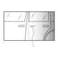
以下、図3及び図5を参照して、第1実施形態と本実施形態との差異を説明する。図5は、本実施形態に係る端末装置30から取得された画像の一例を示す。Second Embodiment
The differences between the first embodiment and this embodiment will be described below with reference to Fig. 3 and Fig. 5. Fig. 5 shows an example of an image acquired from the
本実施形態に係るシステム10、制御装置20、端末装置30、及び照明装置40の構成については第1実施形態のものと同じであるため、説明を省略する。The configurations of the
本実施形態において、制御装置20の制御部21は、端末装置30から取得した画像を複数の領域に分割する。制御部21は、分割した領域の明るさに基づいて照明装置40を制御できる。In this embodiment, the
制御部21は例えば、取得した画像を中央で分割し左右の領域に分ける。図5は、分割された画像の例を示す。図5において破線は画像を分割する線を示す。記号Sは被写体としての車両のキズを示す。制御部21は、分割された画像の左側の領域と右側の領域とのそれぞれについて、明るさが基準値未満であるかどうかを判断する。例えば、制御部21は、左側の領域の明るさは基準値以上であるが、右側の領域の明るさは基準値未満であると判断できる。分割する線の位置、分割される領域の数及び形状等は自由に設定されてよい。For example, the
本実施形態において、制御部21は、第一実施形態と同様に照明装置40を選択した後、分割された画像の明るさに応じて照明装置40を選択する。具体的には、制御部21は、選択した照明装置40のうち、明るさが基準値未満と判断した領域の側に設けられている照明装置40を、さらに絞り込んで選択する。例えば、第1実施形態と同様に、制御部21は照明装置40A及び照明装置40Bを選択しているとする。制御部21は、図5に示す画像の右側の領域の明るさが基準値未満であると判断したとする。この場合、制御部21は、図3で示す照明装置40A及び照明装置40Bのうち、分割した画像の右側の領域の側、すなわち端末装置30の右側に設けられている照明装置40Bを選択する。In this embodiment, the
次に、本実施形態に係るシステム10の動作の、第1実施形態との差異を説明する。Next, we will explain the differences in the operation of the
ステップS101~ステップS102までは、第1実施形態と同様であるため説明を省略する。Steps S101 to S102 are the same as in the first embodiment, so the explanation will be omitted.
ステップS103において、制御装置20は、画像を端末装置30から取得し、複数の領域に分割する。本例では、制御装置20の制御部21は、通信部23を介して、画像を端末装置30から受信する。このようにして制御装置20は画像を取得する。そして制御部21は、取得した画像を中央で分割し左右の領域に分ける。分割する線の位置、分割される領域の数及び形状等は自由に設定されてよい。In step S103, the
ステップS104において、制御部21は、ステップS103で分割した画像の各領域の明るさが基準値未満であるかどうかを判断する。制御部21が、分割した画像の各領域の明るさが基準値以上であると判断した場合、システム10の動作は終了する。制御部21が、いずれかの領域の明るさが基準値未満であると判断した場合、システム10の動作はステップS105に進む。本例では、制御部21は、各領域の各画素の輝度値の平均値が、基準値の130未満であるかどうかを判断する。本例では、右側の領域の各画素の輝度値の平均値は100である。よって制御部21が、右側の領域の明るさが基準値未満であると判断し、システム10の動作はステップS105に進む。In step S104, the
ステップS105~ステップS110までは、第1実施形態と同様であるため説明を省略する。Steps S105 to S110 are the same as in the first embodiment, so the explanation will be omitted.
ステップS111において、制御部21は、第一実施形態と同様に、端末装置30の向いている方向に基づいて照明装置40を選択する。本例では、制御部21は、第一実施形態と同様に照明装置40A及び照明装置40Bを選択する。本実施形態では、制御部21は、分割された画像の明るさに応じて、照明装置40をさらに絞り込んで選択する。分割された画像の明るさに応じて選択される照明装置40の条件は、自由に定められてよい。本例では、制御部21は、選択した照明装置40のうち、明るさが基準値未満と判断した領域の側に設けられている照明装置40をさらに絞り込んで選択する。図5に示す画像において、制御部21は右側の領域の明るさが基準値未満であると判断している。よって制御部21は、図3で示す照明装置40A及び照明装置40Bのうち、右側の領域の側、すなわち端末装置30の右側に設けられている照明装置40Bを選択する。In step S111, the
ステップS112からステップS122までは、選択された照明装置40が照明装置40Bのみである点以外、第1実施形態と同様であるため説明を省略する。Steps S112 to S122 are the same as in the first embodiment except that the
上述のように、制御部21は、画像を複数の領域に分割し、分割した領域の明るさに基づいて照明装置40を制御する。As described above, the
制御部21は、端末装置30の周囲の複数の照明装置40のうち、明るさが基準値未満であると判断した領域の側にある照明装置40を選択して制御できる。すなわち、制御部21は、特に明るさが必要な方向にある照明装置40を選択することができる。よって、専用の照明装置を用いずとも、暗い場所でも対象物を撮影しやすくすることができる。The
(変形例1)
本実施形態の一変形例として、照明装置40の制御部41は、光源部43の点灯可否を検出できる。制御部41は、安全のために光源部43の光量を変化させられない場合、又は発光素子が劣化している場合等に、光源部43が点灯不可であることを検出できる。制御部41は、検出した結果を示す情報を点灯可否情報として、通信部42を介して、制御装置20に送信する。点灯可否情報の送信は制御装置20の要求に応じて行ってもよいし、常時行われてもよい。制御装置20の制御部21は、点灯可否情報を、通信部23を介して受信する。このようにして制御装置20は点灯可否情報を取得する。(Variation 1)
As a modified example of this embodiment, the
本変形例によれば、制御装置20が取得した点灯可否情報に基づき、確実に制御できる照明装置40のみを選択できるようになる。よって、専用の照明装置を用いずとも、暗い場所でも対象物を撮影しやすくすることができる。また、制御装置20は、当該点灯可否情報に基づき、照明装置40の整備を行う者が使用する端末装置等に、発光素子が劣化していることの通知を送信してもよい。これにより、整備が必要な照明装置40が発見されやすくなり、結果的に、照明装置40を継続的に制御することが可能となる。According to this modified example, it becomes possible to select
(変形例2)
本実施形態の一変形例として、制御装置20の制御部21は、画像の取得を行わずに、端末装置30の位置情報に基づいて照明装置40を選択する。制御部21は、選択した照明装置40に指示する動作を決定する。例えば、制御部21は、全ての発光素子を点灯させた状態で光源部43を点灯させる動作を決定する。制御部21は、決定した動作の指示を選択した照明装置40に送信する。照明装置40は、制御部21からの動作の指示に従い、全ての発光素子を点灯させた状態で光源部43を点灯させる。(Variation 2)
As a modified example of this embodiment, the
本変形例によれば、制御部21は、画像の明るさを判断することなく、端末装置30の周囲に設けられた照明装置40を制御する。これにより、制御部21に判断の負荷がかかることなく、素早く端末装置30の周囲の照明装置40を制御することができる。照明装置40が、全ての発光素子を点灯させた状態で光源部43を点灯させるため、最大限の明るさの下で端末装置30が対象物を再度撮影することができる。According to this modified example, the
(変形例3)
本実施形態の一変形例として、制御装置20の制御部21は、取得した画像に、照明装置40からの光が反射して映り込んでしまっていることを判断する。制御部21は、照明装置40からの光が反射して映り込むことで、対象物の一部又は全部が明確に撮影できていないことを判断する。制御部21は、対象物が明確に撮影できていないと判断した場合、光の映り込みを発生させている照明装置40を特定する。制御部21は、特定した照明装置40の光量を減少させる動作の決定を行う。制御部21は、照明装置40の特定を、取得した画像を解析し、端末装置30の位置情報から推定することにより行ってもよい。制御部21は、決定した動作の指示を、通信部23を介して、特定した照明装置40に送信する。照明装置40は、受信した動作の指示に従って光量を減少させる。(Variation 3)
As a modified example of this embodiment, the
本変形例によれば、制御部21が照明装置40の光量をあえて減少するよう制御することができる。これにより、端末装置30が対象物を再度撮影したとき、適切な明るさの画像を取得できる。よって、専用の照明装置を用いずとも、暗い場所でも対象物を撮影しやすくすることができる。According to this modified example, the
本開示は上述の実施形態及び変形例に限定されるものではない。例えば、ブロック図に記載の複数のブロックを統合してもよいし、又は1つのブロックを分割してもよい。フローチャートに記載の複数のステップを記述に従って時系列に実行する代わりに、各ステップを実行する装置の処理能力に応じて、又は必要に応じて、並列的に又は異なる順序で実行してもよい。その他、本開示の趣旨を逸脱しない範囲での変更が可能である。The present disclosure is not limited to the above-described embodiments and modifications. For example, multiple blocks shown in the block diagram may be integrated, or one block may be divided. Instead of executing multiple steps shown in the flowchart in chronological order as described, each step may be executed in parallel or in a different order depending on the processing capacity of the device executing each step, or as needed. Other modifications are possible without departing from the spirit of the present disclosure.
10 システム
11 ユーザ
20 制御装置
21 制御部
22 記憶部
23 通信部
24 入力部
25 出力部
30 端末装置
31 制御部
32 記憶部
33 通信部
34 入力部
35 出力部
36 測位部
37 撮影部
40,40A,40B,40C,40D,40E,40F 照明装置
41 制御部
42 通信部
43 光源部
50 ネットワーク REFERENCE SIGNS
Claims (10)
Translated fromJapanese前記端末装置によって撮影された対象物の画像を前記端末装置から前記通信部を介して取得し、
取得した前記画像に応じて、前記端末装置の周囲に設けられた少なくとも1つの街灯を制御する制御部と
を備え、
前記制御部は、前記通信部を介して前記端末装置の位置を示す位置情報を取得し、前記位置情報に基づいて、複数の前記街灯のうち、前記端末装置の周囲に設けられた前記少なくとも1つの街灯を選択し、
前記画像の明るさが基準値未満であるとき、前記少なくとも1つの街灯の光量を変化させることで前記少なくとも1つの街灯を制御し、
前記位置情報は、前記端末装置が向いている方向の情報を含む、制御装置。 A communication unit that communicates with a terminal device;
acquiring an image of an object photographed by the terminal device from the terminal device via the communication unit;
a control unit that controls at least one street light provided around the terminal device in response to the acquired image;
The control unit acquires location information indicating a location of the terminal device via the communication unit, and selects, based on the location information, the at least one street light provided around the terminal device from among the plurality of street lights;
When the brightness of the image is less than a reference value, controlling the at least one street light by changing an amount of light of the at least one street light;
A control device, wherein the location information includes information about a direction in which the terminal device is facing.
前記判断において、前記画像の明るさが前記基準値以上であると判断するまで、前記対象物の画像の取得及び前記画像に応じた前記街灯の制御を繰り返し実行する、請求項1から4のいずれか一項に記載の制御装置。 The control unit determines whether the brightness of the image is less than the reference value;
The control device according to claim 1 , further comprising: a control unit configured to repeatedly acquire an image of the object and control the street light in accordance with the image until the control unit determines that the brightness of the image is equal to or greater than the reference value.
前記端末装置によって撮影された対象物の画像を前記端末装置から前記通信部を介して取得することと、
取得した前記画像に応じて、前記端末装置の周囲に設けられた少なくとも1つの街灯を制御することと、
前記通信部を介して前記端末装置の位置を示す位置情報を取得することと、
前記位置情報に基づいて、複数の前記街灯のうち、前記端末装置の周囲に設けられた前記少なくとも1つの街灯を選択することと、
前記画像の明るさが基準値未満であるとき、前記少なくとも1つの街灯の光量を変化させることで前記少なくとも1つの街灯を制御することと、を含み、
前記位置情報は、前記端末装置が向いている方向の情報を含む、
制御方法。 A control method executed by a control device having a communication unit that communicates with a terminal device,
acquiring an image of an object photographed by the terminal device from the terminal device via the communication unit;
Controlling at least one street light provided around the terminal device according to the acquired image;
acquiring location information indicating a location of the terminal device via the communication unit;
selecting, from among the plurality of street lights, at least one street light provided around the terminal device based on the location information;
and controlling the at least one street light by changing a light amount of the at least one street light when the brightness of the image is less than a reference value;
The location information includes information about a direction in which the terminal device is facing.
Control methods.
選択した前記街灯を制御することと
をさらに含む、請求項6又は7に記載の制御方法。 selecting the street light located within a reference distance from the position of the terminal device;
8. The method of claim 6 or 7, further comprising: controlling the selected street light.
分割した前記領域の明るさに基づいて前記街灯を制御することと
をさらに含む、請求項6から8のいずれか一項に記載の制御方法。 Dividing the image into a plurality of regions;
The control method according to claim 6 , further comprising: controlling the street light based on the brightness of the divided areas.
前記判断において、前記画像の明るさが前記基準値以上であると判断するまで、前記対象物の画像の取得及び前記画像に応じた前記街灯の制御を繰り返し実行することと
をさらに含む、請求項6から9のいずれか一項に記載の制御方法。 making a determination as to whether the brightness of the image is less than the reference value;
The control method according to claim 6, further comprising repeatedly acquiring an image of the object and controlling the street light in accordance with the image until it is determined that the brightness of the image is equal to or greater than the reference value.
Priority Applications (3)
| Application Number | Priority Date | Filing Date | Title |
|---|---|---|---|
| JP2020178453AJP7494701B2 (en) | 2020-10-23 | 2020-10-23 | Control device, control method, and street light |
| US17/402,944US20220132639A1 (en) | 2020-10-23 | 2021-08-16 | Control device, control method, and streetlight |
| CN202110952242.0ACN114500862B (en) | 2020-10-23 | 2021-08-19 | Control device, control method and street lamp |
Applications Claiming Priority (1)
| Application Number | Priority Date | Filing Date | Title |
|---|---|---|---|
| JP2020178453AJP7494701B2 (en) | 2020-10-23 | 2020-10-23 | Control device, control method, and street light |
Publications (2)
| Publication Number | Publication Date |
|---|---|
| JP2022069330A JP2022069330A (en) | 2022-05-11 |
| JP7494701B2true JP7494701B2 (en) | 2024-06-04 |
Family
ID=81257296
Family Applications (1)
| Application Number | Title | Priority Date | Filing Date |
|---|---|---|---|
| JP2020178453AActiveJP7494701B2 (en) | 2020-10-23 | 2020-10-23 | Control device, control method, and street light |
Country Status (3)
| Country | Link |
|---|---|
| US (1) | US20220132639A1 (en) |
| JP (1) | JP7494701B2 (en) |
| CN (1) | CN114500862B (en) |
Citations (4)
| Publication number | Priority date | Publication date | Assignee | Title |
|---|---|---|---|---|
| JP2004295200A (en) | 2003-03-25 | 2004-10-21 | Toshiba Lighting & Technology Corp | Street emergency call system |
| US20090262189A1 (en) | 2008-04-16 | 2009-10-22 | Videoiq, Inc. | Energy savings and improved security through intelligent lighting systems |
| JP2014154438A (en) | 2013-02-12 | 2014-08-25 | Dainippon Printing Co Ltd | Illumination control device, illumination control method, program for illumination control device, and illumination system |
| JP2018113685A (en) | 2017-01-09 | 2018-07-19 | ローベルト ボツシユ ゲゼルシヤフト ミツト ベシユレンクテル ハフツングRobert Bosch Gmbh | Concept for efficiently responding to emergency call |
Family Cites Families (28)
| Publication number | Priority date | Publication date | Assignee | Title |
|---|---|---|---|---|
| JP4642439B2 (en)* | 2004-11-16 | 2011-03-02 | 三菱電機ビルテクノサービス株式会社 | Lighting control system |
| JP5461842B2 (en)* | 2009-01-28 | 2014-04-02 | エーイーテック株式会社 | Lighting control system |
| JP2011223378A (en)* | 2010-04-12 | 2011-11-04 | Sanyo Electric Co Ltd | Electronic camera |
| TW201208477A (en)* | 2010-08-02 | 2012-02-16 | Hon Hai Prec Ind Co Ltd | Smart street lamp controlling system and the controlling method thereof |
| JP2012204953A (en)* | 2011-03-24 | 2012-10-22 | Nikon Corp | Imaging system, illumination device, and camera |
| US10142595B2 (en)* | 2011-04-13 | 2018-11-27 | Nissan Motor Co., Ltd. | Driving assistance device and method of detecting vehicle adjacent thereto |
| US8866392B2 (en)* | 2011-08-31 | 2014-10-21 | Chia-Teh Chen | Two-level LED security light with motion sensor |
| BR112014020753B1 (en)* | 2012-03-02 | 2021-10-05 | Nissan Motor Co., Ltd | THREE-DIMENSIONAL OBJECT DETECTION DEVICE |
| EP2859779A1 (en)* | 2012-06-12 | 2015-04-15 | Danmarks Tekniske Universitet | Lighting system with illuminance control |
| US11049344B2 (en)* | 2012-07-26 | 2021-06-29 | John C. S. Koo | Dual-mode commercial messaging systems |
| US10679448B2 (en)* | 2012-07-26 | 2020-06-09 | John C. S. Koo | Light-based commercial messaging systems |
| KR20140140867A (en)* | 2013-05-30 | 2014-12-10 | 주식회사 케이엠더블유 | Brightness control device for lighting apparatus |
| TWI511612B (en)* | 2013-12-13 | 2015-12-01 | Lite On Technology Corp | Environment detecting device suitable for street lamp and environment detecting method thereof |
| CN104202881B (en)* | 2014-09-10 | 2018-06-19 | 广州广日电气设备有限公司 | Street lamp control system |
| CN105554407A (en)* | 2015-12-11 | 2016-05-04 | 小米科技有限责任公司 | Shooting control method and shooting control device |
| JP2018054498A (en)* | 2016-09-29 | 2018-04-05 | パナソニックIpマネジメント株式会社 | Notification device and street light system |
| FR3065560B1 (en)* | 2017-04-25 | 2019-04-19 | Continental Automotive France | IMAGE PROCESSING METHOD FOR REMOVAL OF LIGHT ZONES |
| JP7029657B2 (en)* | 2017-11-21 | 2022-03-04 | パナソニックIpマネジメント株式会社 | Shooting equipment and outdoor lighting equipment |
| US10816939B1 (en)* | 2018-05-07 | 2020-10-27 | Zane Coleman | Method of illuminating an environment using an angularly varying light emitting device and an imager |
| PE20210996A1 (en)* | 2018-09-07 | 2021-06-01 | Controle De Donnees Metropolis Inc | LANTERN CAMERA |
| US10780861B2 (en)* | 2019-01-08 | 2020-09-22 | Ford Global Technologies, Llc | Liquid droplet path prediction |
| US11546885B2 (en)* | 2019-02-14 | 2023-01-03 | Qualcomm Incorporated | Sidelink radio frame timing synchronization |
| US11412484B2 (en)* | 2019-05-24 | 2022-08-09 | Qualcomm Incorporated | Sidelink communication across frequency bands |
| KR102846683B1 (en)* | 2019-08-21 | 2025-08-18 | 엘지전자 주식회사 | Method and apparatus for recommending food and drink based on artificial intelligence-based user status |
| US20210071855A1 (en)* | 2019-09-08 | 2021-03-11 | Cello Lighting, Inc. | Multifunction lighting control unit |
| WO2021070768A1 (en)* | 2019-10-09 | 2021-04-15 | ソニー株式会社 | Information processing device, information processing system, and information processing method |
| US11487281B2 (en)* | 2020-03-04 | 2022-11-01 | Ford Global Technologies, Llc | Systems and methods for executing remotely-controlled automated vehicle parking operations |
| US11164010B2 (en)* | 2020-03-16 | 2021-11-02 | Denso International America, Inc. | System for activating a security mode in a vehicle |
- 2020
- 2020-10-23JPJP2020178453Apatent/JP7494701B2/enactiveActive
- 2021
- 2021-08-16USUS17/402,944patent/US20220132639A1/ennot_activeAbandoned
- 2021-08-19CNCN202110952242.0Apatent/CN114500862B/enactiveActive
Patent Citations (4)
| Publication number | Priority date | Publication date | Assignee | Title |
|---|---|---|---|---|
| JP2004295200A (en) | 2003-03-25 | 2004-10-21 | Toshiba Lighting & Technology Corp | Street emergency call system |
| US20090262189A1 (en) | 2008-04-16 | 2009-10-22 | Videoiq, Inc. | Energy savings and improved security through intelligent lighting systems |
| JP2014154438A (en) | 2013-02-12 | 2014-08-25 | Dainippon Printing Co Ltd | Illumination control device, illumination control method, program for illumination control device, and illumination system |
| JP2018113685A (en) | 2017-01-09 | 2018-07-19 | ローベルト ボツシユ ゲゼルシヤフト ミツト ベシユレンクテル ハフツングRobert Bosch Gmbh | Concept for efficiently responding to emergency call |
Also Published As
| Publication number | Publication date |
|---|---|
| US20220132639A1 (en) | 2022-04-28 |
| CN114500862A (en) | 2022-05-13 |
| CN114500862B (en) | 2024-02-23 |
| JP2022069330A (en) | 2022-05-11 |
Similar Documents
| Publication | Publication Date | Title |
|---|---|---|
| US20210254989A1 (en) | Image processing apparatus, image processing method, computer program and computer readable recording medium | |
| US11543256B2 (en) | Electronic apparatus and control method thereof | |
| KR102826623B1 (en) | Method, apparatus, electronic device, computer program and computer readable recording medium for determining road speed limit | |
| US9794736B2 (en) | Low power always-on determination of indoor versus outdoor state | |
| EP3241037A1 (en) | Changing camera parameters based on wireless signal information | |
| CN108335507B (en) | Method and device for providing driving guidance using images captured by cameras | |
| US11830445B2 (en) | System, information processing apparatus, and non-transitory storage medium | |
| US11892311B2 (en) | Image processing apparatus, image processing method, computer program and computer readable recording medium | |
| JP2020085792A (en) | Information providing system, server, mobile terminal, program, and information providing method | |
| KR20220062107A (en) | Light intensity control method, apparatus, electronic device and storage medium | |
| US11270136B2 (en) | Driving support device, vehicle, information providing device, driving support system, and driving support method | |
| CN113192353B (en) | Map generation data collection device, map generation data collection method, and vehicle | |
| US20230247303A1 (en) | Auto exposure using multiple cameras and map prior information | |
| CN111422128B (en) | Server, in-vehicle apparatus, vehicle, storage medium, and information providing method | |
| KR20200044164A (en) | Electronic device and image processing method thereof | |
| JP2010237874A (en) | Vehicle periphery monitoring device | |
| CN113033493A (en) | Target object inspection method and device, electronic equipment and storage medium | |
| JP7494701B2 (en) | Control device, control method, and street light | |
| US20240412528A1 (en) | Signal-to-noise ratio (snr) identification within a scene | |
| GB2523598A (en) | Method for determining the position of a client device | |
| JP2015176155A (en) | Pedestrian protection system and pedestrian protection program | |
| JP7721042B2 (en) | Light distribution control device and light distribution control method | |
| JP2024126103A (en) | Recognition processing device and recognition processing method | |
| CN113869214A (en) | Traffic signal image processing method, device and edge computing device | |
| CN119636788A (en) | A convolutional neural network vehicle lane change assistance system |
Legal Events
| Date | Code | Title | Description |
|---|---|---|---|
| A621 | Written request for application examination | Free format text:JAPANESE INTERMEDIATE CODE: A621 Effective date:20220920 | |
| A977 | Report on retrieval | Free format text:JAPANESE INTERMEDIATE CODE: A971007 Effective date:20230914 | |
| A131 | Notification of reasons for refusal | Free format text:JAPANESE INTERMEDIATE CODE: A131 Effective date:20231031 | |
| A521 | Request for written amendment filed | Free format text:JAPANESE INTERMEDIATE CODE: A523 Effective date:20231212 | |
| A131 | Notification of reasons for refusal | Free format text:JAPANESE INTERMEDIATE CODE: A131 Effective date:20240305 | |
| A521 | Request for written amendment filed | Free format text:JAPANESE INTERMEDIATE CODE: A523 Effective date:20240410 | |
| TRDD | Decision of grant or rejection written | ||
| A01 | Written decision to grant a patent or to grant a registration (utility model) | Free format text:JAPANESE INTERMEDIATE CODE: A01 Effective date:20240423 | |
| A61 | First payment of annual fees (during grant procedure) | Free format text:JAPANESE INTERMEDIATE CODE: A61 Effective date:20240506 | |
| R150 | Certificate of patent or registration of utility model | Ref document number:7494701 Country of ref document:JP Free format text:JAPANESE INTERMEDIATE CODE: R150 |