JP7492193B2 - Liquid ejection head and liquid ejection apparatus - Google Patents
Liquid ejection head and liquid ejection apparatusDownload PDFInfo
- Publication number
- JP7492193B2 JP7492193B2JP2020131018AJP2020131018AJP7492193B2JP 7492193 B2JP7492193 B2JP 7492193B2JP 2020131018 AJP2020131018 AJP 2020131018AJP 2020131018 AJP2020131018 AJP 2020131018AJP 7492193 B2JP7492193 B2JP 7492193B2
- Authority
- JP
- Japan
- Prior art keywords
- filter chamber
- flow path
- inlet
- outlet
- liquid
- Prior art date
- Legal status (The legal status is an assumption and is not a legal conclusion. Google has not performed a legal analysis and makes no representation as to the accuracy of the status listed.)
- Active
Links
- 239000007788liquidSubstances0.000titleclaimsdescription130
- 230000032258transportEffects0.000claimsdescription15
- 239000000976inkSubstances0.000description150
- 239000000758substrateSubstances0.000description136
- 101150016367RIN1 geneProteins0.000description43
- 238000011144upstream manufacturingMethods0.000description33
- 238000004891communicationMethods0.000description25
- 230000000149penetrating effectEffects0.000description12
- 230000035515penetrationEffects0.000description12
- 230000007246mechanismEffects0.000description7
- 230000007723transport mechanismEffects0.000description7
- 238000010586diagramMethods0.000description6
- 230000004308accommodationEffects0.000description5
- 230000001965increasing effectEffects0.000description5
- 239000000463materialSubstances0.000description5
- 239000011347resinSubstances0.000description5
- 229920005989resinPolymers0.000description5
- 239000000853adhesiveSubstances0.000description3
- 230000001070adhesive effectEffects0.000description3
- 239000003086colorantSubstances0.000description3
- 238000007599dischargingMethods0.000description3
- 238000003780insertionMethods0.000description3
- 230000037431insertionEffects0.000description3
- 239000002184metalSubstances0.000description3
- 230000001681protective effectEffects0.000description3
- 230000003247decreasing effectEffects0.000description2
- 238000010438heat treatmentMethods0.000description2
- 230000008531maintenance mechanismEffects0.000description2
- 230000007257malfunctionEffects0.000description2
- XUIMIQQOPSSXEZ-UHFFFAOYSA-NSiliconChemical compound[Si]XUIMIQQOPSSXEZ-UHFFFAOYSA-N0.000description1
- 238000004140cleaningMethods0.000description1
- 230000002542deteriorative effectEffects0.000description1
- 239000000428dustSubstances0.000description1
- 239000004744fabricSubstances0.000description1
- 239000000835fiberSubstances0.000description1
- 238000001914filtrationMethods0.000description1
- 230000001939inductive effectEffects0.000description1
- 238000001746injection mouldingMethods0.000description1
- 238000009940knittingMethods0.000description1
- 238000004519manufacturing processMethods0.000description1
- 239000004745nonwoven fabricSubstances0.000description1
- 238000007789sealingMethods0.000description1
- 239000004065semiconductorSubstances0.000description1
- 229910052710siliconInorganic materials0.000description1
- 239000010703siliconSubstances0.000description1
- 239000002699waste materialSubstances0.000description1
- 238000009941weavingMethods0.000description1
Images


Classifications
- B—PERFORMING OPERATIONS; TRANSPORTING
- B41—PRINTING; LINING MACHINES; TYPEWRITERS; STAMPS
- B41J—TYPEWRITERS; SELECTIVE PRINTING MECHANISMS, i.e. MECHANISMS PRINTING OTHERWISE THAN FROM A FORME; CORRECTION OF TYPOGRAPHICAL ERRORS
- B41J2/00—Typewriters or selective printing mechanisms characterised by the printing or marking process for which they are designed
- B41J2/005—Typewriters or selective printing mechanisms characterised by the printing or marking process for which they are designed characterised by bringing liquid or particles selectively into contact with a printing material
- B41J2/01—Ink jet
- B41J2/015—Ink jet characterised by the jet generation process
- B41J2/04—Ink jet characterised by the jet generation process generating single droplets or particles on demand
- B41J2/045—Ink jet characterised by the jet generation process generating single droplets or particles on demand by pressure, e.g. electromechanical transducers
- B—PERFORMING OPERATIONS; TRANSPORTING
- B41—PRINTING; LINING MACHINES; TYPEWRITERS; STAMPS
- B41J—TYPEWRITERS; SELECTIVE PRINTING MECHANISMS, i.e. MECHANISMS PRINTING OTHERWISE THAN FROM A FORME; CORRECTION OF TYPOGRAPHICAL ERRORS
- B41J2/00—Typewriters or selective printing mechanisms characterised by the printing or marking process for which they are designed
- B41J2/005—Typewriters or selective printing mechanisms characterised by the printing or marking process for which they are designed characterised by bringing liquid or particles selectively into contact with a printing material
- B41J2/01—Ink jet
- B41J2/17—Ink jet characterised by ink handling
- B41J2/175—Ink supply systems ; Circuit parts therefor
- B41J2/17563—Ink filters
- B—PERFORMING OPERATIONS; TRANSPORTING
- B41—PRINTING; LINING MACHINES; TYPEWRITERS; STAMPS
- B41J—TYPEWRITERS; SELECTIVE PRINTING MECHANISMS, i.e. MECHANISMS PRINTING OTHERWISE THAN FROM A FORME; CORRECTION OF TYPOGRAPHICAL ERRORS
- B41J2/00—Typewriters or selective printing mechanisms characterised by the printing or marking process for which they are designed
- B41J2/005—Typewriters or selective printing mechanisms characterised by the printing or marking process for which they are designed characterised by bringing liquid or particles selectively into contact with a printing material
- B41J2/01—Ink jet
- B41J2/17—Ink jet characterised by ink handling
- B41J2/18—Ink recirculation systems
- B—PERFORMING OPERATIONS; TRANSPORTING
- B41—PRINTING; LINING MACHINES; TYPEWRITERS; STAMPS
- B41J—TYPEWRITERS; SELECTIVE PRINTING MECHANISMS, i.e. MECHANISMS PRINTING OTHERWISE THAN FROM A FORME; CORRECTION OF TYPOGRAPHICAL ERRORS
- B41J2/00—Typewriters or selective printing mechanisms characterised by the printing or marking process for which they are designed
- B41J2/005—Typewriters or selective printing mechanisms characterised by the printing or marking process for which they are designed characterised by bringing liquid or particles selectively into contact with a printing material
- B41J2/01—Ink jet
- B41J2/135—Nozzles
- B41J2/14—Structure thereof only for on-demand ink jet heads
- B41J2/14201—Structure of print heads with piezoelectric elements
- B41J2/14233—Structure of print heads with piezoelectric elements of film type, deformed by bending and disposed on a diaphragm
- B—PERFORMING OPERATIONS; TRANSPORTING
- B41—PRINTING; LINING MACHINES; TYPEWRITERS; STAMPS
- B41J—TYPEWRITERS; SELECTIVE PRINTING MECHANISMS, i.e. MECHANISMS PRINTING OTHERWISE THAN FROM A FORME; CORRECTION OF TYPOGRAPHICAL ERRORS
- B41J2/00—Typewriters or selective printing mechanisms characterised by the printing or marking process for which they are designed
- B41J2/005—Typewriters or selective printing mechanisms characterised by the printing or marking process for which they are designed characterised by bringing liquid or particles selectively into contact with a printing material
- B41J2/01—Ink jet
- B41J2/17—Ink jet characterised by ink handling
- B41J2/175—Ink supply systems ; Circuit parts therefor
- B41J2/17503—Ink cartridges
- B41J2/17506—Refilling of the cartridge
- B41J2/17509—Whilst mounted in the printer
- B—PERFORMING OPERATIONS; TRANSPORTING
- B41—PRINTING; LINING MACHINES; TYPEWRITERS; STAMPS
- B41J—TYPEWRITERS; SELECTIVE PRINTING MECHANISMS, i.e. MECHANISMS PRINTING OTHERWISE THAN FROM A FORME; CORRECTION OF TYPOGRAPHICAL ERRORS
- B41J2/00—Typewriters or selective printing mechanisms characterised by the printing or marking process for which they are designed
- B41J2/005—Typewriters or selective printing mechanisms characterised by the printing or marking process for which they are designed characterised by bringing liquid or particles selectively into contact with a printing material
- B41J2/01—Ink jet
- B41J2/17—Ink jet characterised by ink handling
- B41J2/19—Ink jet characterised by ink handling for removing air bubbles
- B—PERFORMING OPERATIONS; TRANSPORTING
- B41—PRINTING; LINING MACHINES; TYPEWRITERS; STAMPS
- B41J—TYPEWRITERS; SELECTIVE PRINTING MECHANISMS, i.e. MECHANISMS PRINTING OTHERWISE THAN FROM A FORME; CORRECTION OF TYPOGRAPHICAL ERRORS
- B41J2/00—Typewriters or selective printing mechanisms characterised by the printing or marking process for which they are designed
- B41J2/005—Typewriters or selective printing mechanisms characterised by the printing or marking process for which they are designed characterised by bringing liquid or particles selectively into contact with a printing material
- B41J2/01—Ink jet
- B41J2/135—Nozzles
- B41J2/145—Arrangement thereof
- B41J2/155—Arrangement thereof for line printing
- B—PERFORMING OPERATIONS; TRANSPORTING
- B41—PRINTING; LINING MACHINES; TYPEWRITERS; STAMPS
- B41J—TYPEWRITERS; SELECTIVE PRINTING MECHANISMS, i.e. MECHANISMS PRINTING OTHERWISE THAN FROM A FORME; CORRECTION OF TYPOGRAPHICAL ERRORS
- B41J2/00—Typewriters or selective printing mechanisms characterised by the printing or marking process for which they are designed
- B41J2/005—Typewriters or selective printing mechanisms characterised by the printing or marking process for which they are designed characterised by bringing liquid or particles selectively into contact with a printing material
- B41J2/01—Ink jet
- B41J2/17—Ink jet characterised by ink handling
- B41J2/175—Ink supply systems ; Circuit parts therefor
- B41J2/17503—Ink cartridges
- B41J2/17513—Inner structure
- B—PERFORMING OPERATIONS; TRANSPORTING
- B41—PRINTING; LINING MACHINES; TYPEWRITERS; STAMPS
- B41J—TYPEWRITERS; SELECTIVE PRINTING MECHANISMS, i.e. MECHANISMS PRINTING OTHERWISE THAN FROM A FORME; CORRECTION OF TYPOGRAPHICAL ERRORS
- B41J2/00—Typewriters or selective printing mechanisms characterised by the printing or marking process for which they are designed
- B41J2/005—Typewriters or selective printing mechanisms characterised by the printing or marking process for which they are designed characterised by bringing liquid or particles selectively into contact with a printing material
- B41J2/01—Ink jet
- B41J2/135—Nozzles
- B41J2/14—Structure thereof only for on-demand ink jet heads
- B41J2/14201—Structure of print heads with piezoelectric elements
- B41J2/14233—Structure of print heads with piezoelectric elements of film type, deformed by bending and disposed on a diaphragm
- B41J2002/14241—Structure of print heads with piezoelectric elements of film type, deformed by bending and disposed on a diaphragm having a cover around the piezoelectric thin film element
- B—PERFORMING OPERATIONS; TRANSPORTING
- B41—PRINTING; LINING MACHINES; TYPEWRITERS; STAMPS
- B41J—TYPEWRITERS; SELECTIVE PRINTING MECHANISMS, i.e. MECHANISMS PRINTING OTHERWISE THAN FROM A FORME; CORRECTION OF TYPOGRAPHICAL ERRORS
- B41J2/00—Typewriters or selective printing mechanisms characterised by the printing or marking process for which they are designed
- B41J2/005—Typewriters or selective printing mechanisms characterised by the printing or marking process for which they are designed characterised by bringing liquid or particles selectively into contact with a printing material
- B41J2/01—Ink jet
- B41J2/135—Nozzles
- B41J2/14—Structure thereof only for on-demand ink jet heads
- B41J2002/14362—Assembling elements of heads
- B—PERFORMING OPERATIONS; TRANSPORTING
- B41—PRINTING; LINING MACHINES; TYPEWRITERS; STAMPS
- B41J—TYPEWRITERS; SELECTIVE PRINTING MECHANISMS, i.e. MECHANISMS PRINTING OTHERWISE THAN FROM A FORME; CORRECTION OF TYPOGRAPHICAL ERRORS
- B41J2/00—Typewriters or selective printing mechanisms characterised by the printing or marking process for which they are designed
- B41J2/005—Typewriters or selective printing mechanisms characterised by the printing or marking process for which they are designed characterised by bringing liquid or particles selectively into contact with a printing material
- B41J2/01—Ink jet
- B41J2/135—Nozzles
- B41J2/14—Structure thereof only for on-demand ink jet heads
- B41J2002/14403—Structure thereof only for on-demand ink jet heads including a filter
- B—PERFORMING OPERATIONS; TRANSPORTING
- B41—PRINTING; LINING MACHINES; TYPEWRITERS; STAMPS
- B41J—TYPEWRITERS; SELECTIVE PRINTING MECHANISMS, i.e. MECHANISMS PRINTING OTHERWISE THAN FROM A FORME; CORRECTION OF TYPOGRAPHICAL ERRORS
- B41J2/00—Typewriters or selective printing mechanisms characterised by the printing or marking process for which they are designed
- B41J2/005—Typewriters or selective printing mechanisms characterised by the printing or marking process for which they are designed characterised by bringing liquid or particles selectively into contact with a printing material
- B41J2/01—Ink jet
- B41J2/135—Nozzles
- B41J2/14—Structure thereof only for on-demand ink jet heads
- B41J2002/14419—Manifold
- B—PERFORMING OPERATIONS; TRANSPORTING
- B41—PRINTING; LINING MACHINES; TYPEWRITERS; STAMPS
- B41J—TYPEWRITERS; SELECTIVE PRINTING MECHANISMS, i.e. MECHANISMS PRINTING OTHERWISE THAN FROM A FORME; CORRECTION OF TYPOGRAPHICAL ERRORS
- B41J2/00—Typewriters or selective printing mechanisms characterised by the printing or marking process for which they are designed
- B41J2/005—Typewriters or selective printing mechanisms characterised by the printing or marking process for which they are designed characterised by bringing liquid or particles selectively into contact with a printing material
- B41J2/01—Ink jet
- B41J2/17—Ink jet characterised by ink handling
- B41J2/175—Ink supply systems ; Circuit parts therefor
- B41J2/17503—Ink cartridges
- B41J2/17513—Inner structure
- B41J2002/17516—Inner structure comprising a collapsible ink holder, e.g. a flexible bag
- B—PERFORMING OPERATIONS; TRANSPORTING
- B41—PRINTING; LINING MACHINES; TYPEWRITERS; STAMPS
- B41J—TYPEWRITERS; SELECTIVE PRINTING MECHANISMS, i.e. MECHANISMS PRINTING OTHERWISE THAN FROM A FORME; CORRECTION OF TYPOGRAPHICAL ERRORS
- B41J2202/00—Embodiments of or processes related to ink-jet or thermal heads
- B41J2202/01—Embodiments of or processes related to ink-jet heads
- B41J2202/11—Embodiments of or processes related to ink-jet heads characterised by specific geometrical characteristics
- B—PERFORMING OPERATIONS; TRANSPORTING
- B41—PRINTING; LINING MACHINES; TYPEWRITERS; STAMPS
- B41J—TYPEWRITERS; SELECTIVE PRINTING MECHANISMS, i.e. MECHANISMS PRINTING OTHERWISE THAN FROM A FORME; CORRECTION OF TYPOGRAPHICAL ERRORS
- B41J2202/00—Embodiments of or processes related to ink-jet or thermal heads
- B41J2202/01—Embodiments of or processes related to ink-jet heads
- B41J2202/12—Embodiments of or processes related to ink-jet heads with ink circulating through the whole print head
- B—PERFORMING OPERATIONS; TRANSPORTING
- B41—PRINTING; LINING MACHINES; TYPEWRITERS; STAMPS
- B41J—TYPEWRITERS; SELECTIVE PRINTING MECHANISMS, i.e. MECHANISMS PRINTING OTHERWISE THAN FROM A FORME; CORRECTION OF TYPOGRAPHICAL ERRORS
- B41J2202/00—Embodiments of or processes related to ink-jet or thermal heads
- B41J2202/01—Embodiments of or processes related to ink-jet heads
- B41J2202/19—Assembling head units
- B—PERFORMING OPERATIONS; TRANSPORTING
- B41—PRINTING; LINING MACHINES; TYPEWRITERS; STAMPS
- B41J—TYPEWRITERS; SELECTIVE PRINTING MECHANISMS, i.e. MECHANISMS PRINTING OTHERWISE THAN FROM A FORME; CORRECTION OF TYPOGRAPHICAL ERRORS
- B41J2202/00—Embodiments of or processes related to ink-jet or thermal heads
- B41J2202/01—Embodiments of or processes related to ink-jet heads
- B41J2202/20—Modules
Landscapes
- Particle Formation And Scattering Control In Inkjet Printers (AREA)
- Ink Jet (AREA)
Description
Translated fromJapanese本発明は、ノズルから液体を噴射する液体噴射ヘッド及び液体噴射装置に関し、特に液体としてインクを噴射するインクジェット式記録ヘッド及びインクジェット式記録装置に関する。The present invention relates to a liquid ejection head and a liquid ejection device that ejects liquid from nozzles, and in particular to an inkjet recording head and an inkjet recording device that ejects ink as the liquid.
インクジェット式プリンターやプロッター等のインクジェット式記録装置に代表される液体噴射装置は、カートリッジやタンク等に貯留されたインクなどの液体を液滴として噴射可能な液体噴射ヘッドを具備する。Liquid ejection devices, such as inkjet printers and plotters, are equipped with a liquid ejection head that can eject liquid such as ink stored in a cartridge or tank as droplets.
このような液体噴射ヘッドは、単体でノズルの長尺化(多ノズル化)や高密度化を行うのは、液体噴射ヘッドが大型化して歩留まりが低下すると共に、製造コストが高価になってしまうため困難である。このため、液体を噴射するヘッドチップを共通の流路部材に複数固定することでノズルを長尺化した液体噴射ヘッドが提案されている。It is difficult to increase the length of nozzles (number of nozzles) or density of such liquid jet heads by themselves, as this would result in a larger liquid jet head, lowering yields, and increasing manufacturing costs. For this reason, liquid jet heads have been proposed that have longer nozzles by fixing multiple head chips that eject liquid to a common flow path member.
液体噴射ヘッドは、例えば、X方向に延在するノズル列が、Y方向に並設されており、各色の液体に対して2つのノズル列が設けられ、流路部材には、各ノズル列に対応して1つのフィルター室が設けられている。そして、流路部材の1つの接続部から導入されたインクは接続部の直下で分岐されて2つのフィルター室に分配された構成が開示されている(例えば、特許文献1参照)。The liquid ejection head has, for example, nozzle rows extending in the X direction arranged in parallel in the Y direction, two nozzle rows for each color of liquid, and the flow path member has one filter chamber corresponding to each nozzle row. A configuration has been disclosed in which ink introduced from one connection part of the flow path member is branched immediately below the connection part and distributed to two filter chambers (see, for example, Patent Document 1).
また、液体噴射ヘッドは、ヘッドチップがノズル列の延在方向にずれて配置され、各ヘッドチップに対応してフィルター室が設けられている。また、液体噴射ヘッドの長手方向において中央側に配置された電気的要素を避けるようにして端部に液体を供給する供給ポートが設けられている構成が開示されている(例えば、特許文献2参照)。The liquid ejection head has head chips arranged offset in the extension direction of the nozzle row, and a filter chamber is provided corresponding to each head chip. A configuration has also been disclosed in which a supply port is provided to supply liquid to the end portion in a manner that avoids electrical elements arranged toward the center in the longitudinal direction of the liquid ejection head (see, for example, Patent Document 2).
しかしながら、特許文献1の液体噴射ヘッドでは、液体が供給される接続部の位置から各フィルター室までの流路長に差があるため、ヘッドチップの同系列のノズル列同士の間で圧力損失にばらつきが生じ、液滴の吐出特性にばらつきが生じてしまい、印刷品質が低下する虞があるという問題がある。However, in the liquid jet head of
また、特許文献2のように、液体噴射ヘッドの長手方向に液体が供給される複数の供給ポートを配置することで、複数のフィルター室が設けられている領域から外れた位置に複数の供給ポートが設けられた構成では、ヘッドチップの同系列のノズル列同士の間で圧力損失がさらにばらつきが生じやすく、液滴の吐出特性にばらつきが生じてしまい、印刷品質が低下する虞があるという問題がある。In addition, as in
なお、このような問題はインクジェット式記録ヘッドだけではなく、インク以外の液体を噴射する液体噴射ヘッドにおいても同様に存在する。Note that this problem exists not only in inkjet recording heads, but also in liquid ejection heads that eject liquids other than ink.
上記課題を解決する本発明の態様は、第1方向に長尺で且つ第2方向に短尺であり、前記第1方向及び前記第2方向に直交する第3方向に液体を噴射する液体噴射ヘッドであって、外部から液体を導入するための第1導入部と、外部から液体を導入するための第2導入部と、第1フィルター室および第2フィルター室を有する第1フィルター室群と、第3フィルター室および第4フィルター室を有する第2フィルター室群と、前記第1導入部から前記第1フィルター室群へ液体を供給する第1供給流路と、前記第2導入部から前記第2フィルター室群へ液体を供給する第2供給流路と、を備え、前記第1導入部、前記第2導入部、前記第1フィルター室群および前記第2フィルター室群が、この順で前記第1方向に向かって並んで配置されていることを特徴とする液体噴射ヘッドにある。The aspect of the present invention that solves the above problem is a liquid jet head that is long in a first direction and short in a second direction, and jets liquid in a third direction perpendicular to the first direction and the second direction, and is characterized in that the liquid jet head includes a first inlet portion for introducing liquid from the outside, a second inlet portion for introducing liquid from the outside, a first filter chamber group having a first filter chamber and a second filter chamber, a second filter chamber group having a third filter chamber and a fourth filter chamber, a first supply flow path that supplies liquid from the first inlet portion to the first filter chamber group, and a second supply flow path that supplies liquid from the second inlet portion to the second filter chamber group, and the first inlet portion, the second inlet portion, the first filter chamber group, and the second filter chamber group are arranged in this order in the first direction.
また、本発明の他の態様は、上記態様に記載の液体噴射ヘッドと、媒体を搬送する搬送部と、を備えることを特徴とする液体噴射装置にある。Another aspect of the present invention is a liquid ejection device comprising the liquid ejection head described above and a transport unit that transports a medium.
以下に本発明を実施形態に基づいて詳細に説明する。ただし、以下の説明は、本発明の一態様を示すものであって、本発明の範囲内で任意に変更可能である。各図において同じ符号を付したものは、同一の部材を示しており、適宜説明が省略されている。また、各図においてX、Y、Zは、互いに直交する3つの空間軸を表している。本明細書では、これらの軸に沿った方向をX方向、Y方向、及びZ方向とする。各図の矢印が向かう方向を正(+)方向、矢印の反対方向を負(-)方向として説明する。また、Z方向は、鉛直方向を示し、+Z方向は鉛直下向き、-Z方向は鉛直上向きを示す。さらに、正方向及び負方向を限定しない3つのX、Y、Zの空間軸については、X軸、Y軸、Z軸として説明する。また、以下の実施形態1では、一例として「第1方向」を+X方向、「第2方向」を+Y方向、「第3方向」を+Z方向としている。The present invention will be described in detail below based on an embodiment. However, the following description shows one aspect of the present invention, and can be arbitrarily modified within the scope of the present invention. In each figure, the same reference numerals indicate the same members, and the description is omitted as appropriate. In each figure, X, Y, and Z represent three spatial axes that are mutually orthogonal. In this specification, the directions along these axes are the X direction, the Y direction, and the Z direction. In each figure, the direction of the arrow is the positive (+) direction, and the opposite direction of the arrow is the negative (-) direction. In addition, the Z direction indicates the vertical direction, the +Z direction is the vertical downward direction, and the -Z direction is the vertical upward direction. Furthermore, the three spatial axes of X, Y, and Z, which are not limited to the positive and negative directions, are described as the X axis, the Y axis, and the Z axis. In the following
(実施形態1)
図1は、本発明の実施形態1に係る「液体噴射装置」の一例であるインクジェット式記録装置1の概略構成を示す図である。 (Embodiment 1)
FIG. 1 is a diagram showing a schematic configuration of an ink
図1に示すように液体噴射装置の一例であるインクジェット式記録装置1は、液体の一種であるインクをインク滴として印刷用紙等の媒体Sに噴射・着弾させて、当該媒体Sに形成されるドットの配列により画像等の印刷を行う印刷装置である。なお、媒体Sとしては、記録用紙の他、樹脂フィルムや布等の任意の材質を用いることができる。As shown in FIG. 1, an
インクジェット式記録装置1は、「液体噴射ヘッド」の一例であるインクジェット式記録ヘッド10(以下、単に記録ヘッド10とも称する)を具備するヘッドモジュール100と、液体容器2と、制御部である制御ユニット3と、媒体Sを送り出す搬送機構4と、移動機構6と、を具備する。The
液体容器2は、ヘッドモジュール100から噴射される複数種類(例えば、複数色)のインクを個別に貯留する。液体容器2としては、例えば、インクジェット式記録装置1に着脱可能なカートリッジ、可撓性のフィルムで形成された袋状のインクパック、インクを補充可能なインクタンクなどが挙げられる。また、特に図示していないが、液体容器2には、色や種類の異なる複数種類のインクが貯留されている。The
制御ユニット3は、特に図示していないが、例えば、CPU(Central Processing Unit)またはFPGA(Field Programmable Gate Array)等の制御装置と半導体メモリ等の記憶装置とを含んで構成される。制御ユニット3は、記憶装置に記憶されたプログラムを制御装置が実行することでインクジェット式記録装置1の各要素、すなわち、搬送機構4、移動機構6、ヘッドモジュール100等を統括的に制御する。Although not specifically shown, the control unit 3 includes a control device such as a CPU (Central Processing Unit) or FPGA (Field Programmable Gate Array) and a storage device such as a semiconductor memory. The control unit 3 comprehensively controls each element of the
搬送機構4は、制御ユニット3によって制御されて媒体Sを-X方向又は+X方向に搬送する「搬送部」の一例であり、例えば、搬送ローラー4aを有する。なお、媒体Sを搬送する搬送機構4は、搬送ローラー4aに限らず、ベルトやドラムによって媒体Sを搬送するものであってもよい。The transport mechanism 4 is an example of a "transport unit" that is controlled by the control unit 3 to transport the medium S in the -X direction or +X direction, and has, for example, a
移動機構6は、制御ユニット3によって制御されてヘッドモジュール100をY軸に沿って+Y方向及び-Y方向に往復させる。移動機構6によってヘッドモジュール100が往復する+Y方向及び-Y方向は、媒体Sが搬送される-X方向又は+X方向に交差する方向である。The
本実施形態の移動機構6は、搬送体7と搬送ベルト8とを具備する。搬送体7は、ヘッドモジュール100を収容する略箱形の構造体、所謂、キャリッジであり、搬送ベルト8に固定される。搬送ベルト8は、Y軸に沿って架設された無端ベルトである。制御ユニット3による制御のもとで搬送ベルト8が回転することでヘッドモジュール100が搬送体7と共にY軸に沿って+Y方向及び-Y方向に往復移動する。なお、液体容器2をヘッドモジュール100と共に搬送体7に搭載することも可能である。The
本実施形態では、液体容器2は2個設けられており、1個の記録ヘッド10に対して2個の液体容器2からインクが供給される。なお、図1では、複数の液体容器2は、纏めて一つに図示している。1個の記録ヘッド10に対応する2個の液体容器2をそれぞれ液体容器2A、液体容器2Bとする。液体容器2Aには供給チューブTAin及び排出チューブTAoutが接続されている。液体容器2Bには、供給チューブTBin及び排出チューブTBoutが接続されている。供給チューブTAin、排出チューブTAout、供給チューブTBin及び排出チューブTBoutを纏めてチューブとも称する。In this embodiment, two
供給チューブTAin及び供給チューブTBinは、ポンプ200によって所定圧力にされた液体容器2A及び液体容器2Bのインクを記録ヘッド10へ供給するチューブである。排出チューブTAout及び排出チューブTBoutは、記録ヘッド10から排出されたインクを液体容器2A及び液体容器2Bへ排出するチューブである。The supply tube TAin and the supply tube TBin are tubes that supply the ink in the
このような液体容器2A、液体容器2B、上記チューブが記録ヘッド10ごとに設けられている。Such
記録ヘッド10は、液体容器2から供給されたインクを制御ユニット3による制御のもとで媒体Sに液滴であるインク滴として噴射する。なお、記録ヘッド10からのインク滴の噴射は、+Z方向に向かって行われる。そして、搬送機構4によって媒体Sが-X方向又は+X方向に搬送されると共に移動機構6によって記録ヘッド10がY軸に沿って搬送される際に、記録ヘッド10が媒体Sにインク滴を噴射することで、媒体Sには所望の画像が形成される。The
ヘッドモジュール100について、図2及び図3を参照して詳細に説明する。図2は、本実施形態に係るヘッドモジュール100の分解斜視図である。図3は、ヘッドモジュール100の平面図である。The
ヘッドモジュール100は、支持体101と複数の記録ヘッド10とを具備する。支持体101は、複数の記録ヘッド10を支持する板状部材である。支持体101には、各記録ヘッド10を保持するための支持孔102が設けられている。支持孔102は、本実施形態では、記録ヘッド10毎に独立して設けられている。もちろん、支持孔102は、複数の記録ヘッド10に亘って連続して設けるようにしてもよい。The
記録ヘッド10は、支持孔102に挿通され、後述する記録ヘッド10のフランジ部35(図4参照)が支持孔102の周縁部に支持されている。記録ヘッド10のヘッドチップ44(図6参照)側が支持体101の+Z方向側の面から突出している。The
各記録ヘッド10には、+X方向及び-X方向の両端部に、固定口103が設けられている。支持体101には、各記録ヘッド10を固定するためのネジ穴104が設けられている。ネジ105が固定口103を挿通してネジ穴104に螺合されることで、各記録ヘッド10が支持体101に固定されている。Each
本実施形態では、記録ヘッド10は、X軸に沿って2個、Y軸に沿って4個、合計8個が支持体101に固定されている。各記録ヘッド10は、後述するノズルNの並設方向がX軸と一致するように配置されている。In this embodiment, a total of eight recording heads 10 are fixed to the
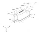
ここで本実施形態の記録ヘッド10について図4~図8を参照して説明する。なお、図4は、記録ヘッド10の斜視図である。図5は、記録ヘッド10を+Z方向に見た分解斜視図である。図6は、記録ヘッド10を-Z方向に見た分解斜視図である。図7は、記録ヘッド10の形状を説明する平面図である。図8は、記録ヘッド10に設けられたヘッドチップ44を+Z方向に見た平面図である。The
図5~図8に示すように、記録ヘッド10は、+X方向に長尺で、+Y方向に短尺な形状を有する。ここで記録ヘッド10が+X方向に長尺で、+Y方向に短尺であるとは、記録ヘッド10を+Z方向に見て、記録ヘッド10を内包する最小面積の長方形をRとしたとき、長辺E1が+X方向に沿って配置されており、短辺E2が+Y方向に沿って配置されていることを言う。As shown in Figures 5 to 8, the
このような記録ヘッド10は、インク滴を吐出するノズルNが設けられた複数のヘッドチップ44と、ヘッドチップ44を保持するホルダー30と、ヘッドチップ44にインクを供給する流路部材60と、ヘッドチップ44に制御信号等を送受信するための配線が接続されるコネクター75と、流路部材60を内部に収容するカバー部材65と、を備えている。本実施形態では、1つの記録ヘッド10は、2つのヘッドチップ44を備えている。なお、詳しくは後述するが、2つのヘッドチップ44は、+X方向に異なる位置に配置されている。このため、本実施形態では、2つのヘッドチップ44について、+X方向側に配置されたヘッドチップ44を第1ヘッドチップ44Aと称し、-X方向側に配置されたヘッドチップ44を第2ヘッドチップ44Bと称する。Such a
ここで、本実施形態のヘッドチップ44についてさらに図9及び図10を参照して説明する。なお、図9はヘッドチップ44の断面図である。図10は第1ヘッドチップ44Aの流路を模式的に表した図である。また、ヘッドチップ44の各方向について、記録ヘッド10に用いられた際の方向、すなわち、X方向、Y方向、Z方向に基づいて説明する。また、以下、第1ヘッドチップ44A及び第2ヘッドチップ44Bに共通する構成の説明では、ヘッドチップ44と記載して説明するが、第1ヘッドチップ44A及び第2ヘッドチップ44Bのそれぞれの特有の構成については第1ヘッドチップ44A又は第2ヘッドチップ44Bと記載して説明する。
図9及び図10に示すように、本実施形態のヘッドチップ44は、圧力室基板482と振動板483と圧電アクチュエーター484と筐体部485と保護基板486とが流路形成基板481の一方側である-Z方向に配置されると共に、流路形成基板481の他方側である+Z方向側にノズルプレート487および緩衝板488が配置された構造体である。As shown in Figures 9 and 10, the
流路形成基板481と圧力室基板482とノズルプレート487とは例えばシリコンの平板材で形成され、筐体部485は例えば樹脂材料の射出成形で形成される。複数のノズルNはノズルプレート487に形成される。ノズルプレート487のうち流路形成基板481とは反対側の表面がノズル面となっている。The flow
流路形成基板481には、開口部481Aと絞り流路である個別流路481Bと連通流路481Cとが形成されている。個別流路481Bおよび連通流路481CはノズルN毎に形成された貫通孔であり、開口部481Aは複数のノズルNに亘って連続する開口である。緩衝板488は、流路形成基板481のうち圧力室基板482とは反対側の表面に設置されて開口部481Aを閉塞する平板材からなるコンプライアンス基板である。開口部481A内の圧力変動は緩衝板488が可撓変形することによって吸収される。The flow
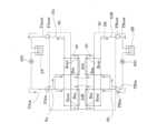
筐体部485には、流路形成基板481の開口部481Aに連通する共通液室であるマニホールドSRが形成される。マニホールドSRは、複数のノズルNに供給されるインクを貯留する空間であり、複数のノズルNに亘って連続して設けられている。また、筐体部485には、図10に示すように、マニホールドSRにインクが上流側から供給される導入口Rinと、マニホールドSRからインクが下流側に排出される排出口Routと、が設けられている。なお、図10において導入口Rinは「入」、排出口Routは「出」で示している。導入口Rinは、詳しくは後述するが、流路部材60の供給管PAin、PBinに第1供給路Sa、第2供給路Sbを介して接続され、排出口Routは、流路部材60の排出管PAout、PBoutに第1排出路Da、第2排出路Dbを介して接続されている。In the
また、本実施形態では、図8及び図10に示すように、ヘッドチップ44には、ノズルNが第1方向である+X方向に沿って並設されたノズル列が設けられている。また、ヘッドチップ44には、ノズルNが+X方向に並設されたノズル列が+Y方向に複数列、本実施形態では、2列設けられている。本実施形態では、1つのヘッドチップ44に設けられた2列のノズル列のうち、-Y方向に配置された一方をノズル列Laと称し、+Y方向に配置された他方をノズル列Lbと称する。そして、本実施形態では、ノズル列Laとノズル列Lbとを合わせてノズル列Lと総称する。これら2列のノズル列La及びノズル列Lbは、それぞれのノズルNの位置が、+X方向に同じ位置、つまり、+Y方向に見て重なる位置に配置されていてもよく、一方のノズル列Laに対して他方のノズル列Lbが、+X方向にノズルNの半ピッチ分ずれて配置されていてもよい。In this embodiment, as shown in FIG. 8 and FIG. 10, the
また、本実施形態では、第1ヘッドチップ44Aの2列のノズル列La及びノズル列Lbを第1ノズル列La1及び第3ノズル列Lb1と称する。そして、第1ヘッドチップ44Aの2つの導入口Rinのうち、第1ノズル列La1に連通する導入口Rinを第1導入口Rin1と称し、第3ノズル列Lb1に連通する導入口Rinを第3導入口Rin3と称する。In addition, in this embodiment, the two nozzle rows La and Lb of the
また、第2ヘッドチップ44Bの2列のノズル列La及びノズル列Lbを第2ノズル列La2及び第4ノズル列Lb2と称する。そして、第2ヘッドチップ44Bの2つの導入口Rinのうち、第2ノズル列La2に連通する導入口Rinを第2導入口Rin2と称し、第4ノズル列Lb2に連通する導入口Rinを第4導入口Rin4と称する。The two nozzle rows La and Lb of the
図10に示すように、第1ヘッドチップ44Aの導入口Rinは、ノズルNの並設方向に対して、マニホールドSRの一端側、本実施形態では-X方向側に配置され、排出口RoutはノズルNの並設方向に対してマニホールドSRの他端側、本実施形態では+X方向側に配置されている。そして、導入口RinからマニホールドSR内に供給されたインクは、排出口RoutからマニホールドSRの外部に排出される。すなわち、マニホールドSR内をインクが循環している。つまり、一つのヘッドチップ44には、導入口Rin、一つのノズル列Lに連なるマニホールドSR、排出口Routに至るインクの循環流路が2つ形成されている。As shown in FIG. 10, the inlet Rin of the
また、図8に示すように、第2ヘッドチップ44Bの導入口Rinは、ノズルNの並設方向に対して、マニホールドSRの他端側、すなわち+X方向側に配置され、排出口RoutはノズルNの並設方向に対してマニホールドSRの一端側、すなわち-X方向側に配置されている。Also, as shown in FIG. 8, the inlet Rin of the
つまり、第1ヘッドチップ44Aと第2ヘッドチップ44Bとは、導入口Rin及び排出口Routの位置が+X方向において逆転した配置となっている。In other words, the positions of the inlet Rin and outlet Rout of the
ヘッドチップ44の圧力室基板482には、ノズルN毎に開口部482Aが形成されている。振動板483は、圧力室基板482のうち流路形成基板481とは反対側の表面に設置された弾性変形可能な平板材である。圧力室基板482の各開口部482Aの内側で振動板483と流路形成基板481とに挟まれた空間は、マニホールドSRから個別流路481Bを介して供給されるインクが充填される圧力室SCとして機能する。各圧力室SCは、流路形成基板481の連通流路481Cを介してノズルNに連通する。In the
振動板483の圧力室基板482とは反対側の表面には、ノズルN毎に圧電アクチュエーター484が形成される。各圧電アクチュエーター484は、圧電素子とも言い相互に対向する電極間に圧電体を介在させた駆動素子である。圧電アクチュエーター484は、駆動信号に基づいて変形することで振動板483を振動させて、圧力室SC内のインクの圧力を変動させることで、圧力室SC内のインクがノズルNから噴射される。また、保護基板486は、複数の圧電アクチュエーター484を保護する。A
なお、圧電アクチュエーター484に替えて、流路内に発熱素子を配置して、発熱素子の発熱で発生するバブルによってノズルNからインク滴を吐出させるものや、振動板483と電極との間に静電気力を発生させて、静電気力によって振動板483を変形させてノズルNからインク滴を吐出させるいわゆる静電式アクチュエーターなどを使用することができる。Instead of the
このようなヘッドチップ44は、ノズルNの並設方向である+X方向に長尺に設けられている。ここでヘッドチップ44が+X方向に長尺とは、ヘッドチップ44を+Z方向に見て、ヘッドチップ44を内包する最小面積の長方形の長辺が、+X方向に沿って配置されていることを言う。また、ヘッドチップ44は、+Y方向に短尺に設けられている。すなわち、ヘッドチップ44を+Z方向に見て、ヘッドチップ44を内包する最小面積の長方形の短辺は、+Y方向に沿って配置されている。このようにヘッドチップ44は、ノズルNの並設方向に長尺に設けることで、ノズルNの並設されたノズル列Lの長さを確保することができると共に、+Y方向に大型化するのを抑制することができる。Such a
図5~図8等に示すように、このようなヘッドチップ44が、1つの記録ヘッド10に複数、本実施形態では、2つ設けられている。具体的には、2つのヘッドチップ44は、記録ヘッド10の共通するホルダー30に保持されている。As shown in Figures 5 to 8, multiple
ホルダー30は、+Z方向側の面に開口する凹部33が設けられ、凹部33の底面、すなわち、凹部33内の-Z方向側の面には凹形状の収容部31が設けられている。凹部33は、固定板36が嵌め込まれて固定される大きさ、形状の開口を有する。また、収容部31は、ヘッドチップ44を収容する程度の大きさ、形状の開口を有する。The
ホルダー30には、ヘッドチップ44と流路部材60との間でインクを流通させる複数の連通路34が設けられている。連通路34は、一端が収容部31の底面、すなわち、収容部31内の-Z方向の面に開口して、ヘッドチップ44の2つの導入口Rin及び2つの排出口Routのそれぞれに連通する。このため、連通路34は、一つのヘッドチップ44につき4個設けられている。また、連通路34の他端は、ホルダー30の-Z方向側の面に開口して、詳しくは後述する流路部材60の第1供給路Sa、第2供給路Sb、第1排出路Da、第2排出路Dbと連通する。The
また、ホルダー30には、ヘッドチップ44と中継基板73とを接続する不図示の配線が挿通される複数の配線挿通孔39が設けられている。配線挿通孔39は、収容部31の底面、すなわち、収容部31内の-Z方向側の面に開口すると共に、ホルダー30の-Z方向側の面に開口して設けられている。The
ホルダー30の-Z方向側には、+X方向及び-X方向にそれぞれ突出する一対のフランジ部35が設けられている。このフランジ部35に、上述したネジ105が挿通される固定口103が+Z方向に貫通して設けられている。A pair of
各ヘッドチップ44は、固定板36に固定されている。具体的には、固定板36は、凹部33に収容される形状に形成されており、所定の場所に露出開口部37が形成されている。そして、各ヘッドチップ44は、緩衝板488が固定板36に覆われ、露出開口部37からノズルN、つまり、ノズルプレート487が露出するように、固定板36に接着剤等で固定されている。このようにして固定板36に固定されたヘッドチップ44は、ノズルプレート487側が+Z方向側となるように収容部31に収容されている。固定板36は凹部33に接着剤等で固定されている。また、ヘッドチップ44の-Z方向側の面は、収容部31の底部、すなわち、収容部31の内面の-Z方向側の面に接着剤で接着されている。Each
すなわち、収容部31と固定板36とによって形成された空間内にヘッドチップ44が収容され、露出開口部37からノズルNが露出している。なお、収容部31は、複数のヘッドチップ44に亘って共通して設けられていてもよい。That is, the
図6に示すように、ホルダー30に保持された複数のヘッドチップ44は、X軸及びY軸により定めるXY平面における位置が互いに異なる位置となるように配置されている。すなわち、+Z方向に見た平面視において、2つのヘッドチップ44は、互いに重ならない位置に設けられている。つまり、第1ノズル列La1と第2ノズル列La2とは、+X方向及び+Y方向の双方に異なる位置にずれて配置されている。なお、2つのヘッドチップ44がXY平面において互いに異なる位置に配置されているとは、ヘッドチップ44のノズル面同士が互いに異なる位置に設けられていることを言う。このため、複数のヘッドチップ44のノズル面以外の部分が+Z方向に見て重なる位置に設けられていてもよい。本実施形態では、図8に示すように、+X方向側に第1ヘッドチップ44Aを配置し、-X方向側に第2ヘッドチップ44Bを配置している。As shown in FIG. 6, the
そして、本実施形態では、図8に示すように、2つのヘッドチップ44のノズル列Lを+X方向で互いに部分的に重複させる位置に配置して、+X方向に亘って連続したノズルNの列を形成している。つまり、第1ヘッドチップ44Aの第1ノズル列La1と、第2ヘッドチップ44Bの第2ノズル列La2とを、+Y方向に見て互いの一部が重なるように配置することで、第1ノズル列La1と第2ノズル列La2とで+X方向に沿って連続したノズルNの列を形成することができる。なお、「第1ヘッドチップ44Aの第1ノズル列La1と、第2ヘッドチップ44Bの第2ノズル列La2とを、+Y方向に見て互いの一部が重なるように配置する」とは、第1ヘッドチップ44Aの第1ノズル列La1が+X方向に存在する範囲、換言すれば第1ノズル列La1の最も+X方向に配置されたノズルNから最も-X方向に配置されたノズルNまでの範囲が、+Y方向に見て、第2ヘッドチップ44Bの第2ノズル列La2が+X方向に存在する範囲、換言すれば第2ノズル列La2の最も+X方向に配置されたノズルNから最も-X方向に配置されたノズルNまでの範囲と重複していることを含んでもよい。つまり、必ずしも、第1ヘッドチップ44Aの第1ノズル列La1を構成するノズルNと、第2ヘッドチップ44Bの第2ノズル列La2を構成するノズルNとが、+X方向において同じ位置に位置している構成には限定されない。8, the nozzle rows L of the two
同様に、第1ヘッドチップ44Aの第3ノズル列Lb1と、第2ヘッドチップ44Bの第4ノズル列Lb2とを、+Y方向に見て互いに重複する位置に配置して、第3ノズル列Lb1と第4ノズル列Lb2とで+X方向に沿って連続したノズルNの列を形成することができる。なお、「第1ヘッドチップ44Aの第3ノズル列Lb1と、第2ヘッドチップ44Bの第4ノズル列Lb2とを、+Y方向に見て互いの一部が重なるように配置する」の定義は、前述の「第1ヘッドチップ44Aの第1ノズル列La1と、第2ヘッドチップ44Bの第2ノズル列La2とを、+Y方向に見て互いの一部が重なるように配置する」の定義と同様であるため重複する説明は省略する。Similarly, the third nozzle row Lb1 of the
このように、第1ヘッドチップ44Aの第1導入口Rin1を第1ヘッドチップ44Aの-X方向側に配置し、第2ヘッドチップ44Bの第2導入口Rin2を第2ヘッドチップ44Bの+X方向側に配置することで、第1導入口Rin1と第2導入口Rin2とを+X方向に比較的近い位置に配置することができる。しかしながら、第1ノズル列La1と第2ノズル列La2とを+Y方向に見て互いの一部が重複するように配置することで、第1ノズル列La1に連通する第1導入口Rin1と第2ノズル列La2に連通する第2導入口Rin2とが、互いに+X方向にずれて配置される。In this way, by arranging the first inlet Rin1 of the
同様に、第1ヘッドチップ44Aの第3導入口Rin3を第1ヘッドチップ44Aの-X方向側に配置し、第2ヘッドチップ44Bの第4導入口Rin4を第2ヘッドチップ44Bの+X方向側に配置することで、第3導入口Rin3と第4導入口Rin4とを+X方向に比較的近い位置に配置することができる。しかしながら、第3ノズル列Lb1と第4ノズル列Lb2とを+Y方向に見て互いの一部が重複するように配置することで、第3ノズル列Lb1に連通する第3導入口Rin3と第4ノズル列Lb2に連通する第4導入口Rin4とが、互いに+X方向にずれて配置される。本実施形態では、第1導入口Rin1及び第3導入口Rin3は、第2導入口Rin2及び第4導入口Rin4に対して、-X方向側にずれた位置に配置されている。Similarly, by arranging the third inlet Rin3 of the
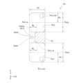
ここで、図7を用いて+Z方向に見た平面視における記録ヘッド10の形状について説明する。記録ヘッド10は、第1部分P1(図7のハッチで示す部分)と、第2部分P2と、第3部分P3と、を備える。The shape of the
記録ヘッド10を内包する最小面積の長方形をRとしたとき、長方形Rの長辺E1はホルダー30の+X方向に沿う辺に重なり、長方形Rの短辺E2はホルダー30の+Y方向に沿う辺に重なる。このような仮想的な長方形Rの長辺E1に平行な中心線をL1とする。When the rectangle with the smallest area that contains the
第1部分P1は、中心線L1が通過する矩形状の部分である。The first portion P1 is a rectangular portion through which the center line L1 passes.
第2部分P2は、第1部分P1から+X方向とは反対方向である-X方向に突出する矩形状の部分である。また、第2部分P2は、+Y方向の寸法W2が、第1部分P1の+Y方向の寸法W1よりも小さい。さらに、第2部分P2は、第1部分P1に対して+Y方向、又は+Y方向とは反対方向である-Y方向に偏って配置されている。なお、第2部分P2が、第1部分P1に対して+Y方向又は-Y方向に偏って配置されているとは、第1部分P1の中心線L1に対して、第2部分P2の中心線L2の位置が一致せず、中心線L2が中心線L1に対して+Y方向又は-Y方向にずれていることを言う。なお、第1部分P1と第2部分P2との側面が直線上に連続していることが好ましい。もちろん、これに限定されず、第1部分P1と第2部分P2との側面が直線上に連続していなくてもよい。The second part P2 is a rectangular part that protrudes from the first part P1 in the -X direction, which is the opposite direction to the +X direction. The dimension W2 of the second part P2 in the +Y direction is smaller than the dimension W1 of the first part P1 in the +Y direction. The second part P2 is arranged offset in the +Y direction or in the -Y direction, which is the opposite direction to the +Y direction, with respect to the first part P1. The second part P2 being offset in the +Y direction or -Y direction with respect to the first part P1 means that the position of the center line L2 of the second part P2 does not coincide with the center line L1 of the first part P1, and the center line L2 is shifted in the +Y direction or -Y direction with respect to the center line L1. It is preferable that the side surfaces of the first part P1 and the second part P2 are continuous on a straight line. Of course, this is not limited to this, and the side surfaces of the first part P1 and the second part P2 do not have to be continuous on a straight line.
また、第2部分P2は、+Y方向の寸法W2は、第1部分P1の+Y方向の寸法W1の半分未満(W2<W1/2)であり、第2部分P2は、第1部分P1の中心よりも+Y方向、又は+Y方向とは反対方向である-Y方向に配置されていることが好ましい。つまり、第2部分P2は、第1部分P1の中心を示す中心線L1が通過しないような+Y方向の寸法及び位置で配置されている。これにより、記録ヘッド10を+Y方向にさらに小型化することができるため、複数の記録ヘッド10を支持体101に配置し易くなり、ヘッドモジュール100を+Y方向に小型化することができる。また、記録ヘッド10のノズル列同士を+X方向で重複させながら+X方向に並べることができる。もちろん、第2部分P2は、中心線L1が通過するような+Y方向の寸法W2を有するものであってもよく、また、第2部分P2を中心線L1が通過するように+Y方向の偏った位置に配置されていてもよい。In addition, the dimension W2 of the second portion P2 in the +Y direction is less than half the dimension W1 of the first portion P1 in the +Y direction (W2<W1/2), and the second portion P2 is preferably disposed in the +Y direction from the center of the first portion P1, or in the -Y direction, which is the opposite direction to the +Y direction. In other words, the second portion P2 is disposed at a dimension and position in the +Y direction such that the center line L1 indicating the center of the first portion P1 does not pass through it. This allows the
第3部分P3は、第1部分P1から+X方向に突出する矩形状の部分である。また、第3部分P3は、+Y方向の寸法が、第1部分P1の+Y方向の寸法よりも小さい。さらに、第3部分P3は、第1部分P1に対して+Y方向、又は+Y方向とは反対方向である-Y方向に偏って配置されている。なお、第3部分P3が、第1部分P1に対して+Y方向又は-Y方向に偏って配置されているとは、第1部分P1の中心線L1に対して、第3部分P3の中心線L3の位置が一致せず、中心線L3が中心線L1に対して+Y方向又は-Y方向にずれていることを言う。The third portion P3 is a rectangular portion that protrudes from the first portion P1 in the +X direction. The dimension of the third portion P3 in the +Y direction is smaller than the dimension of the first portion P1 in the +Y direction. The third portion P3 is disposed offset in the +Y direction with respect to the first portion P1, or offset in the -Y direction, which is the opposite direction to the +Y direction. Note that the third portion P3 being offset in the +Y direction or -Y direction with respect to the first portion P1 means that the position of the center line L3 of the third portion P3 does not coincide with the center line L1 of the first portion P1, and the center line L3 is offset in the +Y direction or -Y direction with respect to the center line L1.
本実施形態の第3部分P3は、中心線L1が通過しないような、+Y方向の幅で、第1部分P1に対して-Y方向に偏って配置されている。もちろん、第3部分P3は、中心線L1が通過するような+Y方向の幅を有するものであってもよく、また、第3部分P3を中心線L1が通過するように-Y方向の偏った位置に配置されていてもよい。The third portion P3 in this embodiment has a width in the +Y direction such that the center line L1 does not pass through it, and is positioned offset in the -Y direction with respect to the first portion P1. Of course, the third portion P3 may have a width in the +Y direction such that the center line L1 passes through it, or may be positioned offset in the -Y direction such that the center line L1 passes through the third portion P3.
このような第1部分P1、第2部分P2及び第3部分P3にヘッドチップ44のノズル面が+X方向及び+Y方向に異なる位置で配置されている。そして、図8に示すように、記録ヘッド10を+X方向に並設してヘッドモジュール100とした場合に、一方の記録ヘッド10(図8では+X方向に配置された記録ヘッド10)の第2部分P2と、他方の記録ヘッド10(図8では-X方向に配置された記録ヘッド10)の第3部分P3とが+Y方向で対向するように配置することで、+X方向で互いに隣り合う記録ヘッド10のノズルNを+X方向で部分的に重複させて、+X方向に亘って連続したノズルNの列を形成することができる。また、記録ヘッド10を+X方向に並設した際に、第2部分P2及び第3部分P3を設けることで、+Y方向に小型化することができる。The nozzle surface of the
なお、本実施形態では、記録ヘッド10に第3部分P3を設けるようにしたが、特にこれに限定されず、第3部分P3を設けなくてもよい。つまり、記録ヘッド10を+X方向に並設してヘッドモジュール100とした場合に、一方の記録ヘッド10の第2部分P2と、他方の記録ヘッド10の第2部分P2とが+Y方向で対向するように配置することで、+X方向で互いに隣り合う記録ヘッド10のノズルNを+X方向で部分的に重複させて、+X方向に亘って連続したノズルNの列を形成することができる。ただし、記録ヘッド10を+X方向に3つ以上並設する場合には、記録ヘッド10には第3部分P3を設けた方が、+X方向に亘って連続したノズルNを容易に形成することができると共に、+Y方向に小型化することができる。In this embodiment, the
ここで、流路部材60についてさらに図11を参照して説明する。なお、図11は、流路を説明する概略図である。Here, the
図5及び図11に示すように、流路部材60は、ヘッドチップ44にインクを供給する流路が形成された部材である。本実施形態の流路部材60には、インクをヘッドチップ44に供給するための第1供給路Sa及び第2供給路Sbと、ヘッドチップ44からインクを排出するための第1排出路Da及び第2排出路Dbと、が形成されている。上述したように、本実施形態のヘッドチップ44には2つのマニホールドSRと、マニホールドSRの各々に導入口Rin及び排出口Routが設けられているため、ヘッドチップ44には、2種類のインクが供給及び排出されて循環する。したがって、流路部材60には、異なるヘッドチップ44に設けられた2つの導入口Rinのそれぞれに連通する第1供給路Sa、異なるヘッドチップ44に設けられた2つの導入口Rinのそれぞれに連通する第2供給路Sbと、異なるヘッドチップ44に設けられた2つの排出口Routのそれぞれに連通する第1排出路Da、及び、異なるヘッドチップ44に設けられた2つの排出口Routのそれぞれに連通する第2排出路Dbとが設けられている。5 and 11, the
また、流路部材60の-Z方向側の面には、-Z方向に突出した円筒状の供給管PAin、供給管PBin、排出管PAout、排出管PBoutが設けられている。図7に示すように、供給管PAinの内部には第1供給路Saの一部である第1導入部Sa1が設けられ、供給管PBinの内部には第2供給路Sbの一部である第2導入部Sb1が設けられている。また、排出管PAoutの内部には第1排出路Daの一部である第1排出部Da3が設けられ、排出管PBoutの内部には第2排出路Dbの一部である第2排出部Db3が設けられている。In addition, the -Z direction surface of the
各供給管PAin、PBin及び排出管PAout、PBoutには、チューブが接続され、または、チューブを取り外すことができるようになっている。供給管PAinには供給チューブTAinが接続され、供給管PBinには供給チューブTBinが接続される。また、排出管PAoutには排出チューブTAoutが接続され、排出管PBoutには排出チューブTBoutが接続される。Tubes are connected to each of the supply pipes PAin, PBin and the exhaust pipes PAout, PBout, or the tubes can be removed. The supply tube TAin is connected to the supply pipe PAin, and the supply tube TBin is connected to the supply pipe PBin. The exhaust tube TAout is connected to the exhaust pipe PAout, and the exhaust tube TBout is connected to the exhaust pipe PBout.
第1供給路Saは、詳しくは後述するが、流路部材60内で2つに分岐している。分岐したそれぞれの流路は、ホルダー30に形成された連通路34(図5参照)に連通している。同様に、第2供給路Sbは、流路部材60内で2つに分岐している。分岐したそれぞれの流路は、ホルダー30に形成された連通路34(図5参照)に連通している。The first supply path Sa, which will be described in detail later, branches into two paths within the
第1排出路Daは、流路部材60内で2つに分岐している。分岐したそれぞれの流路は、ホルダー30に形成された連通路34(図5参照)に連通している。同様に、第2排出路Dbは、流路部材60内で2つに分岐している。分岐したそれぞれの流路は、ホルダー30に形成された連通路34(図5参照)に連通している。The first discharge path Da branches into two within the
液体容器2Aのインクは、ポンプ200により所定圧力に昇圧されて供給チューブTAin、供給管PAinを経由して第1供給路Saに供給される。そして、インクは、第1供給路Saで分岐して、ホルダー30の連通路34を経由し、2つのヘッドチップ44の一方の導入口Rinに供給される。具体的には、第1供給路Saに供給されたインクは、第1ヘッドチップ44Aの第1導入口Rin1と、第2ヘッドチップ44Bの第2導入口Rin2とに供給される。また、第2供給路Sbから供給されたインクは、第1ヘッドチップ44Aの第3導入口Rin3と、第2ヘッドチップ44Bの第4導入口Rin4とに供給される。また、2つのヘッドチップ44の排出口Routから排出されたインクは、ホルダー30の連通路34を経由し、第1排出路Daで合流し、排出管PAout、排出チューブTAoutを経由して液体容器2Aに戻される。液体容器2Aや供給チューブTAin、供給管PAin、排出管PAout、排出チューブTAoutは、第1ヘッドチップ44A、第2ヘッドチップ44Bの各々のノズルNを所定範囲の負圧に保持する構成が取られる。The ink in the
液体容器2Bのインクは、ポンプ200により所定圧力に昇圧されて供給チューブTBin、供給管PBinを経由して第2供給路Sbに供給される。そして、インクは、第2供給路Sbで分岐して、連通路34を経由し、2つのヘッドチップ44の他方の導入口Rinに供給される。2つのヘッドチップ44の排出口Routから排出されたインクは、連通路34を経由し、第2排出路Dbで合流し、排出管PBout、排出チューブTBoutを経由して液体容器2Bに戻される。液体容器2Bや供給チューブTBin、供給管PBin、排出管PBout、排出チューブTBoutも、液体容器2Aと同様に、第1ヘッドチップ44A、第2ヘッドチップ44Bの各々のノズルNを所定範囲の負圧に保持する構成が取られる。The ink in the
なお、上述したように、ホルダー30にはインクが流通する連通路34が設けられており、ホルダー30は流路部材としても機能している。As mentioned above, the
このような流路部材60は、図5に示すように、ホルダー30の-Z側に固定されたカバー部材65内に収容されている。Such a
また、カバー部材65には、-Z方向側の面に、4つの貫通孔67が設けられており、これらの4つの貫通孔67から、供給管PAin、供給管PBin、排出管PAout、排出管PBoutが外部に露出している。Furthermore, the
また、図4及び図5に示すように、カバー部材65の内部には、コネクター75を有する中継基板73が収容されている。中継基板73に設けられたコネクター75は、カバー部材65の-Z方向側の面に設けられた貫通孔である接続開口部63から外部に露出されており、コネクター75に外部の制御ユニット3に接続するための図示しない配線が接続される。As shown in Figs. 4 and 5, a
また、上述した供給管PAin及び供給管PBin、すなわち、詳しくは後述する第1導入部Sa1及び第2導入部Sb1は、記録ヘッド10の第2部分P2に設けられている。また、排出管PAout及び排出管PBout、すなわち、詳しくは後述する第1排出部Da3及び第2排出部Db3は、記録ヘッド10の第3部分P3に設けられている。また、本実施形態の電気的要素であるコネクター75は、記録ヘッド10の第1部分P1に設けられている。本実施形態では、第1導入部Sa1が設けられた供給管PAin及び第2導入部Sb1が設けられた供給管PBinは、この順で+X方向に向かって配置されている。つまり、第1導入部Sa1と第2導入部Sb1とは、+Y方向の位置が同じ位置で、+X方向に異なる位置に配置されており、第1導入部Sa1を基準として、第1導入部Sa1よりも+X方向側に第2導入部Sb1が配置されている。なお、本実施形態では、第1導入部Sa1と第2導入部Sb1とは、+Y方向の位置が同じ位置となるように配置したが、もちろん、これに限定されず、第1導入部Sa1と第2導入部Sb1とは、+Y方向の位置が異なる位置にはいちされていてもよい。また、2つの排出管PAout及びPBoutについても同様に、この順に+X方向に向かって並んで配置されている。The above-mentioned supply pipe PAin and supply pipe PBin, i.e., the first introduction section Sa1 and the second introduction section Sb1, which will be described in detail later, are provided in the second part P2 of the
このように第2部分P2及び第3部分P3に、第1導入部Sa1及び第2導入部Sb1、第1排出部Da3及び第2排出部Db3を設けることで、流路部材60に第1導入部Sa1及び第2導入部Sb1、第1排出部Da3及び第2排出部Db3を設けるスペースを第1部分P1、第2部分P2、第3部分P3よりも外側に設ける必要がなく、流路部材60が大型化するのを抑制することができる。また、第2部分P2及び第3部分P3に、第1導入部Sa1及び第2導入部Sb1、第1排出部Da3及び第2排出部Db3を設けることで、第1部分P1にコネクター75を設けることができ、スペースを有効活用して流路部材60の小型化を図ることができる。さらに、第2部分P2及び第3部分P3に、第1導入部Sa1及び第2導入部Sb1、第1排出部Da3及び第2排出部Db3を設けることで、第1部分P1に設けられたコネクター75から離れた位置に供給管PAin及び供給管PBin、排出管PAout及び排出管PBoutを設けることができる。したがって、第1導入部Sa1及び第2導入部Sb1、第1排出部Da3及び第2排出部Db3が設けられた供給管PAin及び供給管PBin、排出管PAout及び排出管PBoutの各々にチューブを着脱する際に漏出したインクがコネクター75に付着し難く、インクがコネクター75に付着することによる電気的な不具合を抑制することができる。In this way, by providing the first inlet portion Sa1 and the second inlet portion Sb1, and the first outlet portion Da3 and the second outlet portion Db3 in the second portion P2 and the third portion P3, it is not necessary to provide a space for providing the first inlet portion Sa1 and the second inlet portion Sb1, the first outlet portion Da3 and the second outlet portion Db3 in the
なお、第1導入部Sa1の+Y方向の寸法W3は、第2部分P2の+Y方向の寸法W2の半分以上であることが好ましい(W3≧W2/2)。また、第2導入部Sb1の+Y方向の寸法W4は、第2部分P2の+Y方向の寸法W2の半分以上であることが好ましい(W4≧W2/2)。このように、第1導入部Sa1及び第2導入部Sb1のそれぞれの寸法W3、W4を第2部分P2の寸法W2の半分以上とすることで、第1導入部Sa1、第2導入部Sb1を大きくして供給性能を向上させることができる。また、第2部分P2の+Y方向における寸法W2を小さくするために第1導入部Sa1及び第2導入部Sb1を+X方向にずらして配置したとしても、詳しくは後述する、第1導入部Sa1、第2導入部Sb1、第1フィルター室群Fa、第2フィルター室群Fbをこの順に+X方向に向かって配置することで、第1導入部Sa1と第1フィルター室群Faとを接続する第1供給流路Sa2と、第2導入部Sb1と第2フィルター室群Fbとを接続する第2供給流路Sb2との流路長のばらつきを低減することができる。したがって、第1供給流路Sa2と第2供給流路Sb2との圧力損失のばらつきを低減することができる。It is preferable that the dimension W3 in the +Y direction of the first introduction section Sa1 is at least half the dimension W2 in the +Y direction of the second section P2 (W3 ≧ W2/2). It is also preferable that the dimension W4 in the +Y direction of the second introduction section Sb1 is at least half the dimension W2 in the +Y direction of the second section P2 (W4 ≧ W2/2). In this way, by making the dimensions W3 and W4 of the first introduction section Sa1 and the second introduction section Sb1 respectively at least half the dimension W2 of the second section P2, it is possible to increase the size of the first introduction section Sa1 and the second introduction section Sb1 and improve the supply performance. In addition, even if the first introduction section Sa1 and the second introduction section Sb1 are arranged offset in the +X direction to reduce the dimension W2 of the second portion P2 in the +Y direction, by arranging the first introduction section Sa1, the second introduction section Sb1, the first filter chamber group Fa, and the second filter chamber group Fb in this order toward the +X direction, as described in detail below, it is possible to reduce the variation in the flow path length between the first supply flow path Sa2 connecting the first introduction section Sa1 and the first filter chamber group Fa, and the second supply flow path Sb2 connecting the second introduction section Sb1 and the second filter chamber group Fb. Therefore, it is possible to reduce the variation in pressure loss between the first supply flow path Sa2 and the second supply flow path Sb2.
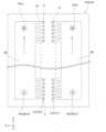
ここで、流路部材60及びホルダー30に設けられた流路についてさらに図12~図20を参照して説明する。図12は主に流路部材60の内部に形成された流路の斜視図である。図13は、主に流路部材60の内部に形成された流路の平面図である。図14は、第1供給路Sa及び第2供給路Sbを抽出した平面図である。図15は、第1供給路Sa及び第2供給路Sbを抽出した側面図である。図16は、第1フィルター室群Fa及び第2フィルター室群Fbの平面図である。図17は、第1フィルター室群Faを抽出した平面図である。図18は、第1排出路Da及び第2排出路Dbを抽出した平面図である。図19は、第1排出路Da及び第2排出路Dbを抽出した側面図である。Here, the flow paths provided in the
図5に示すように、本実施形態の流路部材60は、Z軸に積層された複数の流路基板、本実施形態では、5枚の流路基板を具備する。本実施形態では、Z軸に積層された5枚の流路基板を-Z方向側から+Z方向側に向かって順番に第1流路基板81、第2流路基板82、第3流路基板83、第4流路基板84、第5流路基板85と称する。As shown in FIG. 5, the
このような流路部材60に、図12に示すように、第1供給路Sa及び第2供給路Sbと、第1排出路Da及び第2排出路Dbとが設けられている。そして、流路部材60には、第1供給路Sa及び第2供給路Sbとのそれぞれに種類の異なるインクが供給される。本実施形態では、2つのインクをそれぞれインクIa、インクIbと称する。As shown in FIG. 12, the
ここで、第1供給路Saは、図12~図15等に示すように、上流側から下流側に向かって第1導入部Sa1と、第1供給流路Sa2と、第1フィルター室Fa1及び第2フィルター室Fa2を有する第1フィルター室群Faと、第1流出流路Sa3と、第2流出流路Sa4と、を具備する。As shown in Figures 12 to 15, the first supply path Sa includes, from the upstream side to the downstream side, a first introduction section Sa1, a first supply flow path Sa2, a first filter chamber group Fa having a first filter chamber Fa1 and a second filter chamber Fa2, a first outlet flow path Sa3, and a second outlet flow path Sa4.
第1導入部Sa1は、流路部材60内に外部からインクIaを導入するためのものであり、第1流路基板81の-Z方向に突出する供給管PAin内から第1流路基板81及び第2流路基板82をZ軸に亘って貫通して設けられている。The first introduction section Sa1 is for introducing ink Ia from the outside into the
第1供給流路Sa2は、一端が第1導入部Sa1に接続され、途中で分岐されて分岐された2つの他端が第1フィルター室群Faを構成する第1フィルター室Fa1及び第2フィルター室Fa2にそれぞれ接続されている。具体的には、第1供給流路Sa2は、上流側から下流側に向かって第1供給部Sa21と、第1貫通部Sa22と、第1連結部Sa23と、第1接続部Sa24と、第1分岐部Sa25と、を具備する。One end of the first supply flow path Sa2 is connected to the first introduction portion Sa1, and the other two ends are branched along the way and connected to the first filter chamber Fa1 and the second filter chamber Fa2 that constitute the first filter chamber group Fa. Specifically, the first supply flow path Sa2 comprises, from the upstream side to the downstream side, a first supply portion Sa21, a first penetration portion Sa22, a first connection portion Sa23, a first connection portion Sa24, and a first branch portion Sa25.
第1供給部Sa21は、第2流路基板82と第3流路基板83とが互いに固定された界面に、X軸及びY軸を含むXY平面の面内方向に沿って延設されたものである。第1供給部Sa21は、一端が第1導入部Sa1に接続されている。The first supply section Sa21 extends along the in-plane direction of the XY plane including the X-axis and the Y-axis at the interface where the second
第1貫通部Sa22は、一端が第1供給部Sa21の他端に接続されると共に、他端が第2流路基板82の-Z方向側の面に開口するように、第2流路基板82をZ軸に貫通して設けられている。The first through-portion Sa22 is provided by penetrating the second
第1連結部Sa23は、第1流路基板81と第2流路基板82とが互いに固定された界面に、XY平面の面内方向に沿って延設されたものである。第1連結部Sa23は、一端が第1貫通部Sa22の第2流路基板82の-Z方向側の面に開口する他端に接続されている。The first connecting portion Sa23 extends along the in-plane direction of the XY plane at the interface where the first
第1接続部Sa24は、一端が第1連結部Sa23の他端に接続されると共に、他端が第2流路基板82の+Z方向側の面に開口するように第2流路基板82をZ軸に貫通して設けられている。The first connection portion Sa24 is provided so that one end is connected to the other end of the first connection portion Sa23 and the other end penetrates the second
第1分岐部Sa25は、「分岐流路」に相当するものであり、第2流路基板82と第3流路基板83とが互いに固定された界面に、XY平面の面内方向に沿って延設されたものである。第1分岐部Sa25の途中が、第1接続部Sa24の第2流路基板82の+Z方向側の面に開口する他端に接続されている。この第1接続部Sa24と第1分岐部Sa25とが接続された部分が、第1供給流路Sa2が分岐されて第1フィルター室Fa1と第2フィルター室Fa2とに液体であるインクを分配させる第1分岐位置Sc1となっている。The first branch portion Sa25 corresponds to a "branch flow path" and is provided at the interface where the second
また、第1分岐部Sa25は、一端が第1フィルター室Fa1に接続され、他端が第2フィルター室Fa2に接続されている。Furthermore, one end of the first branch section Sa25 is connected to the first filter chamber Fa1, and the other end is connected to the second filter chamber Fa2.
なお、上述した第1供給部Sa21、第1連結部Sa23、第1分岐部Sa25等の流路は、一方の基板に凹部を形成し、この凹部を他方の基板によって蓋をすることで形成されていてもよく、両方の基板に凹部を形成し、両方の凹部の開口同士を合わせることで形成されていてもよい。The flow paths such as the first supply section Sa21, the first connection section Sa23, and the first branch section Sa25 described above may be formed by forming a recess in one substrate and covering the recess with the other substrate, or may be formed by forming recesses in both substrates and aligning the openings of both recesses.
ここで、第1フィルター室Fa1は、第2流路基板82と第3流路基板83とが互いに固定された界面に設けられている。この第1フィルター室Fa1は、第2流路基板82に設けられた凹部と、第3流路基板83に設けられた凹部との開口同士を合わせることで形成されている。また、第1フィルター室Fa1内には、フィルターFが設けられている。フィルターFは、第2流路基板82と第3流路基板83とが互いに固定された界面に設けられており、第1フィルター室Fa1を上流側の第1上流フィルター室Fa11と下流側の第1下流フィルター室Fa12とに区切っている。つまり、第2流路基板82に設けられた凹部が第1上流フィルター室Fa11となり、第3流路基板83に設けられた凹部が第1下流フィルター室Fa12となっている。このような第1フィルター室Fa1に設けられたフィルターFは、インクに含まれる気泡やゴミなどの異物を補足してインクを濾過するものであり、例えば、金属や樹脂等の繊維を細かく織る又は編むことで複数の微細孔が形成されたシート状のものや、金属や樹脂等の板状部材に複数の微細孔を貫通させたものなどを用いることができる。また、フィルターFは、例えば、金属や樹脂等の不織布を用いてもよい。Here, the first filter chamber Fa1 is provided at the interface where the second
このような第1フィルター室Fa1は、図16及び図17に示すように、+Y方向に長尺となる形状となっている。本実施形態の第1フィルター室Fa1は、+Z方向に見て、+Y方向に沿った辺を長辺、+X方向に沿った辺を短辺とした長方形を基本として、長方形の角を丸めた形状となっている。このように第1フィルター室Fa1は、+Z方向から長方形の角を丸めた形状とすることで、インクに含まれる気泡が角部に滞留し難く、気泡の排出性を向上することができる。なお、第1フィルター室Fa1の形状は、特にこれに限定されず、+Y方向を長軸とする楕円形であってもよく、多角形、正方形、+X方向に長尺となる形状であってもよい。つまり、第1フィルター室Fa1が+Y方向に長尺となっているとは、第1フィルター室Fa1を+Z方向に見て、第1フィルター室Fa1を内包する最小面積の長方形の長辺が+Y方向に沿って配されていることを言う。As shown in Figs. 16 and 17, the first filter chamber Fa1 has a shape that is elongated in the +Y direction. In this embodiment, the first filter chamber Fa1 is a rectangle with the long side along the +Y direction and the short side along the +X direction when viewed in the +Z direction, with the corners of the rectangle rounded. By rounding the corners of the rectangle from the +Z direction in this way, the air bubbles contained in the ink are less likely to remain at the corners, and the air bubbles can be discharged more easily. The shape of the first filter chamber Fa1 is not particularly limited to this, and may be an ellipse with the long axis in the +Y direction, a polygon, a square, or a shape that is elongated in the +X direction. In other words, the first filter chamber Fa1 being elongated in the +Y direction means that when the first filter chamber Fa1 is viewed in the +Z direction, the long side of the rectangle with the smallest area that contains the first filter chamber Fa1 is arranged along the +Y direction.
この第1フィルター室Fa1に第1供給流路Sa2の第1分岐部Sa25の一端が接続されている。ここで、第1供給流路Sa2が第1フィルター室Fa1に連通しているとは、第1供給流路Sa2が、第1フィルター室Fa1のフィルターFよりも上流側である第1上流フィルター室Fa11に連通していることを言う。つまり、第1供給流路Sa2の第1分岐部Sa25の一端は、第1上流フィルター室Fa11の内壁面に開口して設けられている。本実施形態では、第1フィルター室Fa1の内面に開口する第1分岐部Sa25の開口を第1流入口Fa1_inと称する。One end of the first branch portion Sa25 of the first supply flow path Sa2 is connected to this first filter chamber Fa1. Here, the first supply flow path Sa2 being in communication with the first filter chamber Fa1 means that the first supply flow path Sa2 is in communication with the first upstream filter chamber Fa11, which is upstream of the filter F of the first filter chamber Fa1. In other words, one end of the first branch portion Sa25 of the first supply flow path Sa2 is provided so as to open into the inner wall surface of the first upstream filter chamber Fa11. In this embodiment, the opening of the first branch portion Sa25 that opens into the inner surface of the first filter chamber Fa1 is referred to as the first inlet Fa1_in.
また、第1フィルター室Fa1は、インクを流出させる第1流出口Fa1_outを有する。ここで、第1フィルター室Fa1が第1流出口Fa1_outを有するとは、第1流出口Fa1_outが、第1フィルター室Fa1のフィルターFによって区分けされた下流側、すなわち、第1下流フィルター室Fa12に設けられていることを言う。この第1流出口Fa1_outは、第1フィルター室Fa1の内壁に開口する第1流出流路Sa3の開口のことである。The first filter chamber Fa1 also has a first outlet Fa1_out through which ink flows out. Here, the fact that the first filter chamber Fa1 has a first outlet Fa1_out means that the first outlet Fa1_out is provided on the downstream side separated by the filter F of the first filter chamber Fa1, i.e., in the first downstream filter chamber Fa12. This first outlet Fa1_out is the opening of the first outlet flow path Sa3 that opens into the inner wall of the first filter chamber Fa1.
また、第1流出流路Sa3は、第1流出貫通部Sa31と、第1流出部Sa32と、第1流出接続部Sa33と、を具備する。The first outflow passage Sa3 also includes a first outflow penetration portion Sa31, a first outflow portion Sa32, and a first outflow connection portion Sa33.
第1流出貫通部Sa31は、一端が第1下流フィルター室Fa12の+Z方向側の面に開口し、他端が第3流路基板83の+Z方向側の面に開口するように第3流路基板83をZ軸に貫通して設けられている。The first outflow through-portion Sa31 is provided penetrating the third
第1流出部Sa32は、第3流路基板83と第4流路基板84とが互いに固定された界面に、XY平面の面内方向に沿って延設されたものである。第1流出部Sa32は、一端が第1流出貫通部Sa31に接続されている。なお、第1流出部Sa32は、第3流路基板83と第4流路基板84との何れか一方に凹部を設け、他方によって蓋をすることで形成されていてもよく、第3流路基板83と第4流路基板84との両方に凹部を形成し、両方の凹部の開口同士を合わせることで形成されていてもよい。The first outlet section Sa32 is provided at the interface where the third
第1流出接続部Sa33は、一端が第1流出部Sa32に接続され、他端が第4流路基板84の+Z方向側の面に開口するように第4流路基板84をZ軸に貫通して設けられている。この第1流出接続部Sa33の第4流路基板84の+Z方向側の面に開口する他端が、ホルダー30の連通路34を介して、第1ヘッドチップ44Aの第1導入口Rin1に接続されている。The first outflow connection part Sa33 is provided penetrating the fourth
一方、第2フィルター室Fa2は、第2流路基板82と第3流路基板83とが互いに固定された界面に設けられている。すなわち、本実施形態の第2フィルター室Fa2は、第1フィルター室Fa1と同じ界面に設けられている。この第2フィルター室Fa2は、第2流路基板82に設けられた凹部と、第3流路基板83に設けられた凹部との開口同士を合わせることで形成されている。また、第2フィルター室Fa2内には、フィルターFが設けられている。フィルターFは、第2流路基板82と第3流路基板83とが互いに固定される界面に設けられており、第2フィルター室Fa2を上流側の第2上流フィルター室Fa21と下流側の第2下流フィルター室Fa22とに区切っている。なお、第2フィルター室Fa2内に設けられるフィルターFは、第1フィルター室Fa1内に配置されるフィルターFと同様のものを用いることができる。On the other hand, the second filter chamber Fa2 is provided at the interface where the second
このような第2フィルター室Fa2は、+Y方向に長尺となる形状となっている。本実施形態の第2フィルター室Fa2は、+Z方向に見て、+Y方向に沿った辺を長辺、+X方向に沿った辺を短辺とした長方形を基本として、長方形の角を丸めた形状となっている。このように第2フィルター室Fa2は、+Z方向から長方形の角を丸めた形状とすることで、インクに含まれる気泡が角部に滞留し難く、気泡の排出性を向上することができる。なお、第2フィルター室Fa2の形状は、特にこれに限定されず、前述で例示した第1フィルター室Fa1の形状の何れかと同じであってもよい。本実施形態では、第2フィルター室Fa2は、+Z方向に見て第1フィルター室Fa1と同じ形状を有する。このように、第1フィルター室Fa1と第2フィルター室Fa2とを同じ形状で形成することで、それぞれに設けられたフィルターFの有効面積のばらつきを低減して、フィルターFの有効面積のばらつきによる圧力損失のばらつきを低減することができる。Such a second filter chamber Fa2 has a shape that is elongated in the +Y direction. In the present embodiment, the second filter chamber Fa2 is basically a rectangle with the long side along the +Y direction and the short side along the +X direction when viewed in the +Z direction, with the corners of the rectangle rounded. In this way, the second filter chamber Fa2 has a rectangular shape with rounded corners from the +Z direction, so that air bubbles contained in the ink are less likely to remain at the corners, and the discharge of air bubbles can be improved. The shape of the second filter chamber Fa2 is not particularly limited to this, and may be the same as any of the shapes of the first filter chamber Fa1 exemplified above. In this embodiment, the second filter chamber Fa2 has the same shape as the first filter chamber Fa1 when viewed in the +Z direction. In this way, by forming the first filter chamber Fa1 and the second filter chamber Fa2 in the same shape, the variation in the effective area of the filter F provided in each of them can be reduced, and the variation in pressure loss due to the variation in the effective area of the filter F can be reduced.
この第2フィルター室Fa2に第1供給流路Sa2の第1分岐部Sa25の他端が接続されている。ここで、第1供給流路Sa2が第2フィルター室Fa2に連通しているとは、第1供給流路Sa2が、第2フィルター室Fa2のフィルターFよりも上流側である第2上流フィルター室Fa21に連通していることを言う。つまり、第1供給流路Sa2の第1分岐部Sa25の他端は、第2上流フィルター室Fa21の内壁面に開口して設けられている。本実施形態では、第2フィルター室Fa2の内面に開口する第1分岐部Sa25の開口を第2流入口Fa2_inと称する。The other end of the first branch portion Sa25 of the first supply flow path Sa2 is connected to this second filter chamber Fa2. Here, the first supply flow path Sa2 communicating with the second filter chamber Fa2 means that the first supply flow path Sa2 communicates with the second upstream filter chamber Fa21, which is upstream of the filter F of the second filter chamber Fa2. In other words, the other end of the first branch portion Sa25 of the first supply flow path Sa2 is provided so as to open into the inner wall surface of the second upstream filter chamber Fa21. In this embodiment, the opening of the first branch portion Sa25 that opens into the inner surface of the second filter chamber Fa2 is referred to as the second inlet Fa2_in.
また、第2フィルター室Fa2は、インクを流出させる第2流出口Fa2_outを有する。ここで、第2フィルター室Fa2が第2流出口Fa2_outを有するとは、第2流出口Fa2_outが、第2フィルター室Fa2のフィルターFによって区分けされた下流側、すなわち、第2下流フィルター室Fa22に設けられていることを言う。この第2流出口Fa2_outは、第2フィルター室Fa2の内壁に開口する第2流出流路Sa4の開口のことである。The second filter chamber Fa2 also has a second outlet Fa2_out through which ink flows out. Here, the fact that the second filter chamber Fa2 has a second outlet Fa2_out means that the second outlet Fa2_out is provided on the downstream side separated by the filter F of the second filter chamber Fa2, i.e., in the second downstream filter chamber Fa22. This second outlet Fa2_out is the opening of the second outlet flow path Sa4 that opens into the inner wall of the second filter chamber Fa2.
また、第2流出流路Sa4は、第2流出貫通部Sa41と、第2流出部Sa42と、第2流出接続部Sa43と、を具備する。The second outflow passage Sa4 also includes a second outflow penetration portion Sa41, a second outflow portion Sa42, and a second outflow connection portion Sa43.
第2流出貫通部Sa41は、一端が第2下流フィルター室Fa22の+Z方向側の面に開口し、他端が第3流路基板83の+Z方向側の面に開口するように第3流路基板83をZ軸に貫通して設けられている。The second outflow through-portion Sa41 is provided penetrating the third
第2流出部Sa42は、第3流路基板83と第4流路基板84とが互いに固定された界面に、XY平面の面内方向に沿って延設されたものである。第2流出部Sa42は、一端が第2流出貫通部Sa41に接続されている。なお、第2流出部Sa42は、第3流路基板83と第4流路基板84との何れか一方に凹部を設け、他方によって蓋をすることで形成されていてもよく、第3流路基板83と第4流路基板84との両方に凹部を形成し、両方の凹部の開口同士を合わせることで形成されていてもよい。The second outlet section Sa42 is provided at the interface where the third
第2流出接続部Sa43は、一端が第2流出部Sa42に接続され、他端が第4流路基板84の+Z方向側の面に開口するように第4流路基板84をZ軸に貫通して設けられている。この第2流出接続部Sa43の第4流路基板84の+Z方向側の面に開口する他端が、ホルダー30の連通路34を介して第2ヘッドチップ44Bの第2導入口Rin2に接続されている。The second outflow connection part Sa43 is provided penetrating the fourth
このような第1供給路Saを構成する第1フィルター室Fa1と第2フィルター室Fa2とを有する第1フィルター室群Faは、図7に示す第1部分P1に形成されている。このように第1フィルター室群Faを第1部分P1に設けることで、第1フィルター室群Faを設けるスペースを確保して、比較的広い面積のフィルターFを設けることができ、フィルターFによる圧力損失を低減して、供給不良が生じるのを抑制することができる。The first filter chamber group Fa, which has the first filter chamber Fa1 and the second filter chamber Fa2 that constitute the first supply path Sa, is formed in the first part P1 shown in FIG. 7. By providing the first filter chamber group Fa in the first part P1 in this way, it is possible to ensure space for providing the first filter chamber group Fa, and to provide a filter F with a relatively large area, thereby reducing pressure loss due to the filter F and preventing poor supply.
また、第1フィルター室Fa1と第2フィルター室Fa2とは、同じ界面である第2流路基板82と第3流路基板83との界面に設けられている。また、第1フィルター室Fa1と第2フィルター室Fa2とは、+Y方向に間隔を空けて配置されている。すなわち、第1フィルター室Fa1と第2フィルター室Fa2とは、+X方向に見て、重ならない位置に配置されている。The first filter chamber Fa1 and the second filter chamber Fa2 are provided at the same interface between the second
また、図17に示すように、第1フィルター室Fa1と第2フィルター室Fa2とは、+Y方向に見て互いに少なくとも一部が重なる位置に配置されている。なお、第1フィルター室Fa1と第2フィルター室Fa2とは、+Y方向に見て互いに完全に重なる位置に配置されていてもよい。本実施形態では、第1フィルター室Fa1と第2フィルター室Fa2とは、+Y方向に見て一部が重なるように+X方向にずれて配置されている。本実施形態では、第1フィルター室Fa1に対して、第2フィルター室Fa2は+X方向にずらした位置に配置されている。つまり、第1フィルター室Fa1の-X方向側の一部と、第2フィルター室Fa2の+X方向側の一部とが、+Y方向に見て重なるように配置されている。このように第1フィルター室Fa1と第2フィルター室Fa2とは、+Y方向に見て一部が重なるように+X方向にずれて配置することで、ノズル列同士がずれて配置される記録ヘッド10において、2つの導入口Rinが+X方向にずれている場合であっても、第1フィルター室Fa1と導入口Rinとの距離及び第2フィルター室Fa2と導入口Rinとの距離を短くすることができる。したがって、2つの導入口Rinに供給されるインクの圧力損失のばらつきを低減することができる。すなわち、第1フィルター室Fa1からインクが供給される第1ヘッドチップ44Aの第1導入口Rin1と、第2フィルター室Fa2からインクが供給される第2ヘッドチップ44Bの第2導入口Rin2とが、互いに+X方向にずれて配置されている場合であっても、第1フィルター室Fa1と第2フィルター室Fa2とを+X方向にずらして配置することで、第1フィルター室Fa1から第1ヘッドチップ44Aの第1導入口Rin1までの距離と、第2フィルター室Fa2から第2ヘッドチップ44Bの第2導入口Rin2までの距離と、を短くすることができる。したがって、第1流出流路Sa3と第2流出流路Sa4との圧力損失のばらつきを低減することができる。したがって、第1フィルター室Fa1と第2フィルター室Fa2との+X方向のずれ量は、第1導入口Rin1と第2導入口Rin2との+X方向のずれ量と同程度とするのが好ましい。このように、第1フィルター室Fa1と第2フィルター室Fa2との+X方向のずれ量を、第1導入口Rin1と第2導入口Rin2との+X方向のずれ量と同程度とすることで、第1フィルター室Fa1から第1ヘッドチップ44Aの第1導入口Rin1までの流路長と、第2フィルター室Fa2から第2ヘッドチップ44Bの第2導入口Rin2までの流路長とのばらつきを抑制して、第1導入口Rin1に連通する第1ノズル列La1と第2導入口Rin2に連通する第2ノズル列La2とから吐出されるインク滴の吐出特性のばらつきを低減することができる。As shown in FIG. 17, the first filter chamber Fa1 and the second filter chamber Fa2 are disposed in a position where they at least partially overlap each other when viewed in the +Y direction. The first filter chamber Fa1 and the second filter chamber Fa2 may be disposed in a position where they completely overlap each other when viewed in the +Y direction. In this embodiment, the first filter chamber Fa1 and the second filter chamber Fa2 are disposed shifted in the +X direction so that they partially overlap when viewed in the +Y direction. In this embodiment, the second filter chamber Fa2 is disposed in a position shifted in the +X direction with respect to the first filter chamber Fa1. In other words, a portion of the first filter chamber Fa1 on the -X direction side and a portion of the second filter chamber Fa2 on the +X direction side are disposed so as to overlap when viewed in the +Y direction. In this way, the first filter chamber Fa1 and the second filter chamber Fa2 are arranged offset in the +X direction so as to overlap partially when viewed in the +Y direction, so that even if the two inlets Rin are offset in the +X direction in the
また、第1フィルター室Fa1と導入口Rinとの距離及び第2フィルター室Fa2と導入口Rinとの距離を短くすることができるので、不図示のメンテナンス機構によって吸引クリーニングを行うことで記録ヘッド10のフィルターFよりも下流に滞留している気泡をノズルNから排出する際に廃棄するインクの量を低減することができる。なお、不図示のメンテナンス機構とは、少なくとも、ノズルNが形成されたノズル面を封止可能なキャップと、キャップに連通する廃液流路と、ノズル面を封止している状態でキャップ内を負圧にするためのポンプ等の負圧発生手段と、を有する。In addition, since the distance between the first filter chamber Fa1 and the inlet Rin and the distance between the second filter chamber Fa2 and the inlet Rin can be shortened, the amount of ink discarded when air bubbles remaining downstream of the filter F of the
また、第1フィルター室Fa1と第2フィルター室Fa2とが+Y方向に見て重なる部分の+X方向における幅W5は、第1フィルター室Fa1の+X方向における幅W6の半分よりも小さいことが好ましい(W5<W6/2)。このように第1フィルター室Fa1と第2フィルター室Fa2とが重なる幅W5を、第1フィルター室Fa1の幅W6の半分よりも小さくすることで、第1流入口Fa1_inを第1フィルター室Fa1の端部に配置しても、また、第2流入口Fa2_inを第2フィルター室Fa2の端部に配置しても第1フィルター室Fa1と第2フィルター室Fa2とを+Y方向に近づけ易くすることができる。そして、第1フィルター室Fa1と第2フィルター室Fa2とを+Y方向に近づけることで、記録ヘッド10を+Y方向に小型化することができる。また、第1フィルター室Fa1と第2フィルター室Fa2とを+Y方向に近づけることで、+Y方向に並設されたヘッドチップ44を互いに+Y方向に近づけることができ、異なるヘッドチップ44から吐出されるインク滴の吐出タイミングの差を低減することができる。したがって、インク滴の媒体Sへの着弾位置ズレを抑制することができる。In addition, it is preferable that the width W5 in the +X direction of the portion where the first filter chamber Fa1 and the second filter chamber Fa2 overlap when viewed in the +Y direction is smaller than half the width W6 of the first filter chamber Fa1 in the +X direction (W5<W6/2). By making the width W5 where the first filter chamber Fa1 and the second filter chamber Fa2 overlap smaller than half the width W6 of the first filter chamber Fa1 in this way, it is possible to easily bring the first filter chamber Fa1 and the second filter chamber Fa2 closer to each other in the +Y direction even if the first inlet Fa1_in is disposed at the end of the first filter chamber Fa1, or the second inlet Fa2_in is disposed at the end of the second filter chamber Fa2. And by bringing the first filter chamber Fa1 and the second filter chamber Fa2 closer to each other in the +Y direction, the
そして、第1接続部Sa24と第1分岐部Sa25とが連通する第1分岐位置Sc1は、+Z方向に見た平面視において、第1フィルター室Fa1と第2フィルター室Fa2との間に設けられている。The first branch position Sc1, where the first connection portion Sa24 and the first branch portion Sa25 communicate with each other, is located between the first filter chamber Fa1 and the second filter chamber Fa2 in a plan view looking in the +Z direction.
ここで、第1分岐位置Sc1が、+Z方向の平面視において第1フィルター室Fa1と第2フィルター室Fa2との間に配置されているとは、図17にハッチングで示す第1フィルター室Fa1と第2フィルター室Fa2とに挟まれた領域S1の範囲内にあることを言う。なお、第1フィルター室Fa1と第2フィルター室Fa2とに挟まれた領域S1は、言い換えると、+Z方向に見て、第1フィルター室Fa1と第2フィルター室Fa2との双方に接する-X方向の接線S1aと、第1フィルター室Fa1と第2フィルター室Fa2との双方に接する+X方向の接線S1bとの間において、第1フィルター室Fa1と第2フィルター室Fa2とに挟まれた領域のことである。Here, the first branch position Sc1 being located between the first filter chamber Fa1 and the second filter chamber Fa2 in a plan view in the +Z direction means that it is within the range of the area S1 sandwiched between the first filter chamber Fa1 and the second filter chamber Fa2, which is shown hatched in Figure 17. In other words, the area S1 sandwiched between the first filter chamber Fa1 and the second filter chamber Fa2 is the area sandwiched between the first filter chamber Fa1 and the second filter chamber Fa2, between the tangent line S1a in the -X direction that touches both the first filter chamber Fa1 and the second filter chamber Fa2, and the tangent line S1b in the +X direction that touches both the first filter chamber Fa1 and the second filter chamber Fa2, when viewed in the +Z direction.
ちなみに、第1分岐位置Sc1は、第1分岐部Sa25に開口する第1接続部Sa24の開口の中心位置Sa24cを言う。したがって、第1分岐位置Sc1の中心位置Sa24cが、領域S1の範囲内にあれば、その他の部分は、領域S1の範囲外にあってもよい。The first branch position Sc1 refers to the center position Sa24c of the opening of the first connection portion Sa24 that opens into the first branch portion Sa25. Therefore, as long as the center position Sa24c of the first branch position Sc1 is within the range of region S1, the other parts may be outside the range of region S1.
このように、第1分岐位置Sc1を第1フィルター室Fa1と第2フィルター室Fa2との間に配置することで、第1分岐位置Sc1から第1フィルター室Fa1及び第2フィルター室Fa2までの第1分岐部Sa25の流路長を短くして、分岐される前の第1導入部Sa1から第1分岐位置Sc1までの共通する流路の流路長を長くすることができる。したがって、第1分岐部Sa25の流路長が長くなる場合に比べて、第1供給流路Sa2のレイアウトを簡素化することができる。In this way, by arranging the first branch position Sc1 between the first filter chamber Fa1 and the second filter chamber Fa2, the flow path length of the first branch section Sa25 from the first branch position Sc1 to the first filter chamber Fa1 and the second filter chamber Fa2 can be shortened, and the flow path length of the common flow path from the first introduction section Sa1 before branching to the first branch position Sc1 can be lengthened. Therefore, the layout of the first supply flow path Sa2 can be simplified compared to when the flow path length of the first branch section Sa25 is long.
また、第1フィルター室Fa1に第1供給流路Sa2からインクが流入する第1流入口Fa1_inと第2フィルター室Fa2に第1供給流路Sa2からインクが流入する第2流入口Fa2_inとは、+Y方向に見て、第1フィルター室Fa1と第2フィルター室Fa2とが重なる部分、すなわち、図17に示すS2の範囲内に配置されている。The first inlet Fa1_in through which ink flows from the first supply flow path Sa2 into the first filter chamber Fa1 and the second inlet Fa2_in through which ink flows from the first supply flow path Sa2 into the second filter chamber Fa2 are located in the area where the first filter chamber Fa1 and the second filter chamber Fa2 overlap when viewed in the +Y direction, that is, within the range S2 shown in FIG. 17.
このように、第1流入口Fa1_inと第2流入口Fa2_inとを、第1フィルター室Fa1と第2フィルター室Fa2とが重なる部分の領域S3の範囲内に配置することで、第1分岐位置Sc1から第1流入口Fa1_inまでの第1分岐部Sa25の流路長と、第1分岐位置Sc1から第2流入口Fa2_inまでの第1分岐部Sa25の流路長を比較的短くすることができる。したがって、第1分岐位置Sc1から第1流入口Fa1_inまでの第1分岐部Sa25と、第1分岐位置Sc1から第2流入口Fa2_inまでの第1分岐部Sa25との圧力損失のばらつきをさらに低減することができる。ちなみに、第1流入口Fa1_inと第2流入口Fa2_inとを、第1フィルター室Fa1と第2フィルター室Fa2とが重なる部分の領域S2の範囲外に配置すると、第1分岐位置Sc1から第1流入口Fa1_in及び第2流入口Fa2_inまでの流路長が長くなり、流路長に比例する圧力損失のばらつきも大きくなってしまう。In this way, by arranging the first inlet Fa1_in and the second inlet Fa2_in within the range of the region S3 where the first filter chamber Fa1 and the second filter chamber Fa2 overlap, the flow path length of the first branch section Sa25 from the first branch position Sc1 to the first inlet Fa1_in and the flow path length of the first branch section Sa25 from the first branch position Sc1 to the second inlet Fa2_in can be made relatively short. Therefore, the variation in pressure loss between the first branch section Sa25 from the first branch position Sc1 to the first inlet Fa1_in and the first branch section Sa25 from the first branch position Sc1 to the second inlet Fa2_in can be further reduced. Incidentally, if the first inlet Fa1_in and the second inlet Fa2_in are positioned outside the range of the region S2 where the first filter chamber Fa1 and the second filter chamber Fa2 overlap, the flow path length from the first branch position Sc1 to the first inlet Fa1_in and the second inlet Fa2_in will be longer, and the variation in pressure loss, which is proportional to the flow path length, will also be greater.
また、第1流入口Fa1_inは、第1フィルター室Fa1の第2フィルター室Fa2に対して対向する面に配置され、第2流入口Fa2_inは、第2フィルター室Fa2の第1フィルター室Fa1に対して対向する面に配置されている。すなわち、第1流入口Fa1_inは、第1フィルター室Fa1の+Y方向の面に配置され、第2流入口Fa2_inは、第2フィルター室Fa2の-Y方向の面に配置されている。このように第1流入口Fa1_inを、第1フィルター室Fa1の第2フィルター室Fa2に対して対向する面に配置し、第2流入口Fa2_inを、第2フィルター室Fa2の第1フィルター室Fa1に対して対向する面に配置することで、第1分岐位置Sc1を第1フィルター室Fa1及び第2フィルター室Fa2の直前に配置することができる。もちろん、第1流入口Fa1_inは、第1フィルター室Fa1の+Y方向の面以外の面、つまり、+Z方向の面、-Z方向の面、+X方向の面、-X方向の面、-Y方向の面に配置してもよい。ただし、第1流入口Fa1_inを+Y方向の面以外の面に配置した場合には、第1流入口Fa1_inを+Y方向の面に設けた場合に比べて、第1分岐位置Sc1を第1フィルター室Fa1の直前に配置することができなくなると共に第1分岐部Sa25の流路長が長くなるため、第1分岐部Sa25の圧力損失にばらつきが生じてしまう。第1流入口Fa1_inを、第1フィルター室Fa1の第2フィルター室Fa2に対して対向する面に配置することで、第1分岐位置Sc1を第1フィルター室Fa1の直前に配置して、第1分岐部Sa25の流路長を短くして、第1分岐部Sa25の圧力損失のばらつきを低減することができる。なお、第2流入口Fa2_inについても同様である。The first inlet Fa1_in is disposed on the surface of the first filter chamber Fa1 facing the second filter chamber Fa2, and the second inlet Fa2_in is disposed on the surface of the second filter chamber Fa2 facing the first filter chamber Fa1. That is, the first inlet Fa1_in is disposed on the surface of the first filter chamber Fa1 facing the +Y direction, and the second inlet Fa2_in is disposed on the surface of the second filter chamber Fa2 facing the -Y direction. In this way, by disposing the first inlet Fa1_in on the surface of the first filter chamber Fa1 facing the second filter chamber Fa2, and disposing the second inlet Fa2_in on the surface of the second filter chamber Fa2 facing the first filter chamber Fa1, the first branch position Sc1 can be disposed immediately before the first filter chamber Fa1 and the second filter chamber Fa2. Of course, the first inlet Fa1_in may be disposed on a surface other than the +Y direction surface of the first filter chamber Fa1, that is, on the +Z direction surface, the -Z direction surface, the +X direction surface, the -X direction surface, or the -Y direction surface. However, when the first inlet Fa1_in is disposed on a surface other than the +Y direction surface, the first branch position Sc1 cannot be disposed immediately before the first filter chamber Fa1 and the flow path length of the first branch section Sa25 becomes longer than when the first inlet Fa1_in is disposed on the +Y direction surface, so that the pressure loss of the first branch section Sa25 varies. By disposing the first inlet Fa1_in on the surface of the first filter chamber Fa1 facing the second filter chamber Fa2, the first branch position Sc1 can be disposed immediately before the first filter chamber Fa1, the flow path length of the first branch section Sa25 can be shortened, and the variation in the pressure loss of the first branch section Sa25 can be reduced. The same applies to the second inlet Fa2_in.
また、第1流入口Fa1_inの+X方向の幅W7及び第2流入口Fa2_inの+X方向の幅W8は、第1フィルター室Fa1と第2フィルター室Fa2とが+Y方向に見て重なる部分の+X方向における幅W5よりも小さい(W7<W5、W8<W5)。このように、第1流入口Fa1_inの幅W7及び第2流入口Fa2_inの幅W8を、第1フィルター室Fa1と第2フィルター室Fa2とが+Y方向に見て重なる部分の+X方向における幅W5よりも小さくすることで、第1フィルター室Fa1、第2フィルター室Fa2に流入するインクの流速を速くすることができ、第1フィルター室Fa1及び第2フィルター室Fa2内のインクに含まれる気泡を下流側に排出する、いわゆる気泡排出性を向上することができる。The +X-direction width W7 of the first inlet Fa1_in and the +X-direction width W8 of the second inlet Fa2_in are smaller than the +X-direction width W5 of the portion where the first filter chamber Fa1 and the second filter chamber Fa2 overlap as seen in the +Y direction (W7<W5, W8<W5). In this way, by making the width W7 of the first inlet Fa1_in and the width W8 of the second inlet Fa2_in smaller than the +X-direction width W5 of the portion where the first filter chamber Fa1 and the second filter chamber Fa2 overlap as seen in the +Y direction, the flow rate of the ink flowing into the first filter chamber Fa1 and the second filter chamber Fa2 can be increased, and the so-called bubble discharge performance, which discharges air bubbles contained in the ink in the first filter chamber Fa1 and the second filter chamber Fa2 to the downstream side, can be improved.
また、第1分岐部Sa25は、第1流入口Fa1_inと第2流入口Fa2_inとを結ぶ直線上に形成されている。また、第1分岐部Sa25は、+X方向及び+Y方向に対して傾斜して配置されている。本実施形態では、第1流入口Fa1_inは、第1フィルター室Fa1の+X方向側の端部に設けられ、第2流入口Fa2_inは、第2フィルター室Fa2の-X方向側の端部に設けられている。そして、上述したように、第1フィルター室Fa1と第2フィルター室Fa2とは、+Y方向に見て互いの一部が重なるようにして+X方向にずれて配置されている。このため、第1流入口Fa1_inに対して、第2流入口Fa2_inは、-X方向側に配置されている。したがって、第1分岐部Sa25は、第1流入口Fa1_inから第2流入口Fa2_inに向かって-X方向及び+Y方向の成分を有するベクトル方向に沿って形成されている。The first branch portion Sa25 is formed on a straight line connecting the first inlet Fa1_in and the second inlet Fa2_in. The first branch portion Sa25 is arranged at an incline with respect to the +X and +Y directions. In this embodiment, the first inlet Fa1_in is provided at the end of the first filter chamber Fa1 on the +X direction side, and the second inlet Fa2_in is provided at the end of the second filter chamber Fa2 on the -X direction side. As described above, the first filter chamber Fa1 and the second filter chamber Fa2 are arranged shifted in the +X direction so that they partially overlap each other when viewed in the +Y direction. Therefore, the second inlet Fa2_in is arranged on the -X direction side with respect to the first inlet Fa1_in. Therefore, the first branch portion Sa25 is formed along a vector direction having components in the -X and +Y directions from the first inlet Fa1_in toward the second inlet Fa2_in.
また、第1分岐部Sa25の一部と第1フィルター室Fa1の内壁の一部とは、+Z方向に見た平面視で+Y方向に沿って連続して設けられている。すなわち、第1分岐部Sa25の+X方向の内壁Sa25aは、第1フィルター室Fa1の+X方向の内壁Fa1aと、+Y方向に沿った直線上に連続して設けられている。つまり、第1分岐部Sa25の内壁Sa25aと、第1フィルター室Fa1の内壁Fa1aとは、面一となるように設けられている。In addition, a portion of the first branch portion Sa25 and a portion of the inner wall of the first filter chamber Fa1 are provided continuously along the +Y direction in a plan view seen in the +Z direction. That is, the +X direction inner wall Sa25a of the first branch portion Sa25 is provided continuously on a straight line along the +Y direction with the +X direction inner wall Fa1a of the first filter chamber Fa1. In other words, the inner wall Sa25a of the first branch portion Sa25 and the inner wall Fa1a of the first filter chamber Fa1 are provided so as to be flush with each other.
このように第1分岐部Sa25の内壁Sa25aと第1フィルター室Fa1の内壁Fa1aとを+Y方向に沿って連続して設けることで、第1分岐部Sa25からのインクは、内壁Sa25a及びFa1aに沿って第1流入口Fa1_inから第1フィルター室Fa1に流入する。したがって、第1フィルター室Fa1に流入する際にインクの流速が低下するのを抑制して、第1フィルター室Fa1内のインクに含まれる気泡の排出性、いわゆる気泡排出性を向上することができる。By providing the inner wall Sa25a of the first branch portion Sa25 and the inner wall Fa1a of the first filter chamber Fa1 continuously along the +Y direction in this manner, the ink from the first branch portion Sa25 flows into the first filter chamber Fa1 from the first inlet Fa1_in along the inner walls Sa25a and Fa1a. This prevents the ink from decreasing in flow rate when it flows into the first filter chamber Fa1, improving the ability to expel air bubbles contained in the ink in the first filter chamber Fa1, i.e., the ability to expel air bubbles.
同様に、第1分岐部Sa25の一部と第2フィルター室Fa2の内壁の一部とは、+Z方向に見た平面視で+Y方向に沿って連続して設けられている。すなわち、第1分岐部Sa25の-X方向の内壁Sa25bは、第2フィルター室Fa2の-X方向の内壁Fa2aと、+Y方向に沿った直線上に連続して設けられている。つまり、第1分岐部Sa25の内壁Sa25bと、第2フィルター室Fa2の内壁Fa2aとは、面一となるように設けられている。Similarly, a portion of the first branch portion Sa25 and a portion of the inner wall of the second filter chamber Fa2 are provided continuously along the +Y direction in a plan view seen in the +Z direction. That is, the -X direction inner wall Sa25b of the first branch portion Sa25 is provided continuously on a straight line along the +Y direction with the -X direction inner wall Fa2a of the second filter chamber Fa2. In other words, the inner wall Sa25b of the first branch portion Sa25 and the inner wall Fa2a of the second filter chamber Fa2 are provided so as to be flush with each other.
このように第1分岐部Sa25の内壁Sa25bと第2フィルター室Fa2の内壁Fa2aとを+Y方向に沿って連続して設けることで、第1分岐部Sa25からのインクは、内壁Sa25b及びFa2aに沿って第2流入口Fa2_inから第2フィルター室Fa2に流入する。したがって、第2フィルター室Fa2に流入する際にインクの流速が低下するのを抑制して、第2フィルター室Fa2内のインクに含まれる気泡の排出性、いわゆる気泡排出性を向上することができる。By providing the inner wall Sa25b of the first branch portion Sa25 and the inner wall Fa2a of the second filter chamber Fa2 continuously along the +Y direction in this manner, the ink from the first branch portion Sa25 flows into the second filter chamber Fa2 from the second inlet Fa2_in along the inner walls Sa25b and Fa2a. This prevents the ink from decreasing in flow rate when it flows into the second filter chamber Fa2, improving the ability to expel air bubbles contained in the ink in the second filter chamber Fa2, or the so-called air bubble expulsion ability.
また、第1分岐部Sa25のうち、第1分岐位置Sc1から第1流入口Fa1_inまでの間には、第1流入口Fa1_inの+X方向における幅W7よりも、+X方向における幅が小さい部分が設けられている。本実施形態では、第1分岐部Sa25は、-X方向の内壁と第1フィルター室Fa1の+Y方向の内壁とを湾曲した曲面、所謂R面で接続することで、第1分岐部Sa25は、第1流入口Fa1_inの直前に、+X方向の幅が、第1流入口Fa1_inよりも小さい第1絞り部Sa25cが設けられている。第1絞り部Sa25cの幅Wa1は、第1流入口Fa1_inの幅W7よりも小さい(Wa1<W7)。The first branch portion Sa25 has a portion between the first branch position Sc1 and the first inlet Fa1_in that has a width in the +X direction smaller than the width W7 of the first inlet Fa1_in in the +X direction. In this embodiment, the first branch portion Sa25 connects the inner wall in the -X direction and the inner wall in the +Y direction of the first filter chamber Fa1 with a curved surface, a so-called R surface, so that the first branch portion Sa25 has a first throttling portion Sa25c immediately before the first inlet Fa1_in that has a width in the +X direction smaller than the first inlet Fa1_in. The width Wa1 of the first throttling portion Sa25c is smaller than the width W7 of the first inlet Fa1_in (Wa1<W7).
このように、第1分岐部Sa25に、第1絞り部Sa25cを設けることで、第1分岐部Sa25から第1フィルター室Fa1に流入するインクの流速を速くすることができ、第1フィルター室Fa1内のインクに含まれる気泡の排出性を向上することができる。In this way, by providing the first throttling section Sa25c in the first branch section Sa25, the flow rate of the ink flowing from the first branch section Sa25 into the first filter chamber Fa1 can be increased, and the ability to remove air bubbles contained in the ink in the first filter chamber Fa1 can be improved.
同様に、第1分岐部Sa25のうち、第1分岐位置Sc1から第2流入口Fa2_inまでの間には、第2流入口Fa2_inの+X方向における幅W8よりも、+X方向における幅が小さい部分が設けられている。本実施形態では、第1分岐部Sa25は、+X方向の内壁と第2フィルター室Fa2の-Y方向の内壁とを湾曲した曲面、所謂R面で接続することで、第1分岐部Sa25は、第2流入口Fa2_inの直前に、+X方向の幅が、第2流入口Fa2_inよりも小さい第2絞り部Sa25dが設けられている。第2絞り部Sa25dの幅Wa2は、第2流入口Fa2_inの幅W8よりも小さい(Wa2<W8)。Similarly, the first branch portion Sa25 has a portion between the first branch position Sc1 and the second inlet Fa2_in that has a width in the +X direction smaller than the width W8 of the second inlet Fa2_in in the +X direction. In this embodiment, the first branch portion Sa25 connects the inner wall in the +X direction and the inner wall in the -Y direction of the second filter chamber Fa2 with a curved surface, a so-called R surface, so that the first branch portion Sa25 has a second throttling portion Sa25d immediately before the second inlet Fa2_in that has a width in the +X direction smaller than that of the second inlet Fa2_in. The width Wa2 of the second throttling portion Sa25d is smaller than the width W8 of the second inlet Fa2_in (Wa2<W8).
このように、第1分岐部Sa25に、第2絞り部Sa25dを設けることで、第1分岐部Sa25から第2フィルター室Fa2に流入するインクの流速を速くすることができ、第2フィルター室Fa2内のインクに含まれる気泡の排出性を向上することができる。In this way, by providing the second throttling section Sa25d in the first branch section Sa25, the flow rate of the ink flowing from the first branch section Sa25 into the second filter chamber Fa2 can be increased, and the ability to remove air bubbles contained in the ink in the second filter chamber Fa2 can be improved.
また、本実施形態では、上述したように第1分岐部Sa25、第1流入口Fa1_in及び第2流入口Fa2_inは、+Z方向において同じ位置に配置されている。このように第1分岐部Sa25を第1流入口Fa1_in及び第2流入口Fa2_inと+Z方向に同じ位置に設けることで、第1分岐位置Sc1を第1流入口Fa1_in及び第2流入口Fa2_inと+Z方向に同じ位置に配置することができる。そして、第1分岐位置Sc1を第1流入口Fa1_in及び第2流入口Fa2_inと+Z方向に同じ位置に配置することで、第1分岐位置Sc1を第1フィルター室群FaのZ軸における上方、すなわち-Z方向や、下方、すなわち+Z方向などに配置する構成に比べて、第1分岐位置Sc1を第1フィルター室Fa1及び第2フィルター室Fa2の直前に配置することができる。したがって、第1供給路Saの第1分岐位置Sc1よりも前の共通部分の流路長を長くすることができ、第1供給路Saのレイアウトを簡素化することができる。In addition, in this embodiment, as described above, the first branch portion Sa25, the first inlet Fa1_in, and the second inlet Fa2_in are arranged at the same position in the +Z direction. In this way, by providing the first branch portion Sa25 at the same position in the +Z direction as the first inlet Fa1_in and the second inlet Fa2_in, the first branch position Sc1 can be arranged at the same position in the +Z direction as the first inlet Fa1_in and the second inlet Fa2_in. And, by arranging the first branch position Sc1 at the same position in the +Z direction as the first inlet Fa1_in and the second inlet Fa2_in, the first branch position Sc1 can be arranged just before the first filter chamber Fa1 and the second filter chamber Fa2, compared to a configuration in which the first branch position Sc1 is arranged above the Z axis of the first filter chamber group Fa, i.e., in the -Z direction, or below, i.e., in the +Z direction. Therefore, the length of the common portion of the first supply path Sa before the first branch position Sc1 can be increased, and the layout of the first supply path Sa can be simplified.
もちろん、第1分岐部Sa25は、特にこれに限定されず、第1分岐部Sa25の一部が第1流入口Fa1_in、第2流入口Fa2_inと+Z方向に異なる位置に配置されていてもよい。また、第1分岐位置Sc1を、第1流入口Fa1_in、第2流入口Fa2_inと+Z方向に異なる位置に配置してもよい。さらに、第1分岐位置Sc1を、第1流入口Fa1_in、第2流入口Fa2_inと+Z方向に同じ位置に配置し、第1分岐部Sa25の一部を、第1流入口Fa1_in、第2流入口Fa2_inと+Z方向で異なる位置に配置してもよい。Of course, the first branch portion Sa25 is not particularly limited to this, and a part of the first branch portion Sa25 may be disposed at a different position in the +Z direction from the first inlet Fa1_in and the second inlet Fa2_in. Also, the first branch position Sc1 may be disposed at a different position in the +Z direction from the first inlet Fa1_in and the second inlet Fa2_in. Furthermore, the first branch position Sc1 may be disposed at the same position in the +Z direction as the first inlet Fa1_in and the second inlet Fa2_in, and a part of the first branch portion Sa25 may be disposed at a different position in the +Z direction from the first inlet Fa1_in and the second inlet Fa2_in.
また、第1流出口Fa1_outは、+Y方向に見て、第2フィルター室Fa2に重ならない部分で、且つ+Y方向において、第1フィルター室Fa1の中心Fa1cに対して第2フィルター室Fa2から遠くに配置されている。つまり、第1流出口Fa1_outは、+X方向において領域S2の外側、すなわち、領域S2よりも-X方向側で、且つ+Y方向における第1フィルター室Fa1の中心Fa1cよりも-Y方向側の領域S3に配置されている。すなわち、第1フィルター室Fa1を+Z方向に見て、第1フィルター室Fa1を内包する最小面積の長方形において、対角となる一方の角部、+X方向及び+Y方向の角部に第1流入口Fa1_inが設けられ、対角となる他方の角部、すなわち、-X方向及び-Y方向の角部近傍に第1流出口Fa1_outが設けられている。このため、第1流出口Fa1_outを第1流入口Fa1_inから離して配置することができ、第1フィルター室Fa1内を流れるインクに淀みが生じるのを抑制することができる。つまり、第1フィルター室Fa1内のインクは、第1流入口Fa1_inと第1流出口Fa1_outとを結ぶ直線上に最も速く流れ、この直線上から離れるに従って遅く流れる。このため、第1流入口Fa1_inと第1流出口Fa1_outとを結ぶ直線を第1フィルター室Fa1の対角線上において離れた位置に配置することで、第1フィルター室Fa1内でインクに淀みが生じるのを低減することができる。The first outlet Fa1_out is disposed in a portion that does not overlap with the second filter chamber Fa2 when viewed in the +Y direction, and is disposed farther from the second filter chamber Fa2 in the +Y direction with respect to the center Fa1c of the first filter chamber Fa1. In other words, the first outlet Fa1_out is disposed outside the region S2 in the +X direction, that is, in the region S3 on the -X side of the region S2 and on the -Y side of the center Fa1c of the first filter chamber Fa1 in the +Y direction. In other words, when the first filter chamber Fa1 is viewed in the +Z direction, the first inlet Fa1_in is provided at one diagonal corner, the corners in the +X direction and the +Y direction, in a rectangle of the smallest area that contains the first filter chamber Fa1, and the first outlet Fa1_out is provided near the other diagonal corner, that is, the corners in the -X direction and the -Y direction. For this reason, the first outlet Fa1_out can be positioned away from the first inlet Fa1_in, making it possible to prevent stagnation of the ink flowing inside the first filter chamber Fa1. In other words, the ink in the first filter chamber Fa1 flows fastest on the straight line connecting the first inlet Fa1_in and the first outlet Fa1_out, and flows slower the further away from this straight line. For this reason, by positioning the straight line connecting the first inlet Fa1_in and the first outlet Fa1_out at a position away from the diagonal of the first filter chamber Fa1, it is possible to reduce stagnation of the ink inside the first filter chamber Fa1.
なお、第2流出口Fa2_outについても、第1流出口Fa1_outと同様に、+Y方向に見て、第1フィルター室Fa1に重ならない部分で、且つ+Y方向において、第2フィルター室Fa2の中心Fa2cに対して第1フィルター室Fa1から遠くに配置されている。つまり、第2流出口Fa2_outは、+X方向において領域S2の外側、すなわち、領域S2よりも+X方向側で、且つ+Y方向における第2フィルター室Fa2の中心Fa2cよりも+Y方向側の領域S4に配置されている。このため、第2流出口Fa2_outを第2流入口Fa2_inから離して配置することができ、第2フィルター室Fa2内を流れるインクに淀みが生じるのを低減することができる。The second outlet Fa2_out, like the first outlet Fa1_out, is disposed in a portion that does not overlap with the first filter chamber Fa1 when viewed in the +Y direction, and is disposed farther from the first filter chamber Fa1 in the +Y direction than the center Fa2c of the second filter chamber Fa2. In other words, the second outlet Fa2_out is disposed outside the region S2 in the +X direction, that is, in the region S4 that is on the +X side of the region S2 and on the +Y side of the center Fa2c of the second filter chamber Fa2 in the +Y direction. This allows the second outlet Fa2_out to be disposed away from the second inlet Fa2_in, reducing stagnation of the ink flowing through the second filter chamber Fa2.
つまり、第1流入口Fa1_in及び第1流出口Fa1_outと、第2流入口Fa2_in及び第2流出口Fa2_outとを、第1分岐位置Sc1を中心として点対称となる位置に配置することができる。In other words, the first inlet Fa1_in and the first outlet Fa1_out, and the second inlet Fa2_in and the second outlet Fa2_out can be arranged at positions that are point-symmetric with respect to the first branch position Sc1.
また、第1流入口Fa1_inから第1流出口Fa1_outへ向かうインクの流れと、第2流入口Fa2_inから第2流出口Fa2_outへ向かうインクの流れと、を逆方向にすることができる。したがって、第1流出口Fa1_outと第2流出口Fa2_outとの位置を、第1分岐位置Sc1を中心とした点対称となる位置に配置することができる。このため、第1ノズル列La1と第2ノズル列La2とが+X方向にずれていると、各ノズル列Lに連通する導入口Rin、すなわち、第1導入口Rin1と第2導入口Rin2とも+X方向にずれてしまうが、第1導入口Rin1と第2導入口Rin2との+X方向のズレに合わせて、第1流出口Fa1_outと第2流出口Fa2_outとの位置をずらすことができる。よって、第1流出口Fa1_outから第1導入口Rin1までの距離、及び、第2流出口Fa2_outから第2導入口Rin2までの距離を短くできると共に、短い流路長によって圧力損失のばらつきを抑制することができる。In addition, the flow of ink from the first inlet Fa1_in to the first outlet Fa1_out and the flow of ink from the second inlet Fa2_in to the second outlet Fa2_out can be reversed. Therefore, the positions of the first outlet Fa1_out and the second outlet Fa2_out can be arranged at positions that are point symmetrical with respect to the first branch position Sc1. Therefore, if the first nozzle row La1 and the second nozzle row La2 are misaligned in the +X direction, the inlets Rin communicating with each nozzle row L, i.e., the first inlet Rin1 and the second inlet Rin2, are also misaligned in the +X direction. However, the positions of the first outlet Fa1_out and the second outlet Fa2_out can be misaligned in accordance with the misalignment in the +X direction between the first inlet Rin1 and the second inlet Rin2. Therefore, the distance from the first outlet Fa1_out to the first inlet Rin1 and the distance from the second outlet Fa2_out to the second inlet Rin2 can be shortened, and the short flow path length can suppress variation in pressure loss.
第2供給路Sbは、第1供給路Saと同様の構成を有する。すなわち、第2供給路Sbは、図12~図15等に示すように、上流側から下流側に向かって第2導入部Sb1と、第2供給流路Sb2と、第3フィルター室Fb1及び第4フィルター室Fb2を有する第2フィルター室群Fbと、第3流出流路Sb3と、第4流出流路Sb4と、を具備する。The second supply path Sb has the same configuration as the first supply path Sa. That is, as shown in Figures 12 to 15, the second supply path Sb includes, from the upstream side to the downstream side, a second inlet portion Sb1, a second supply flow path Sb2, a second filter chamber group Fb having a third filter chamber Fb1 and a fourth filter chamber Fb2, a third outlet flow path Sb3, and a fourth outlet flow path Sb4.
第2導入部Sb1は、流路部材60内に外部からインクIbを導入するためのものであり、第1流路基板81の-Z方向に突出する供給管PBin内から第1流路基板81、第2流路基板82及び及び第3流路基板83をZ軸に亘って貫通して設けられている。The second introduction section Sb1 is for introducing ink Ib from the outside into the
第2供給流路Sb2は、一端が第2導入部Sb1に接続され、途中で分岐されて分岐された2つの他端が第2フィルター室群Fbを構成する第3フィルター室Fb1及び第4フィルター室Fb2にそれぞれ接続されている。具体的には、第2供給流路Sb2は、上流側から下流側に向かって第2供給部Sb21と、第2貫通部Sb22と、第2連結部Sb23と、第2接続部Sb24と、第2分岐部Sb25と、を具備する。One end of the second supply flow path Sb2 is connected to the second introduction portion Sb1, and the other two ends are branched along the way and connected to the third filter chamber Fb1 and the fourth filter chamber Fb2 that constitute the second filter chamber group Fb. Specifically, the second supply flow path Sb2 includes, from the upstream side to the downstream side, a second supply portion Sb21, a second through portion Sb22, a second connecting portion Sb23, a second connecting portion Sb24, and a second branch portion Sb25.
なお、第2供給流路Sb2の第2供給部Sb21、第2貫通部Sb22、第2連結部Sb23、第2接続部Sb24、第2分岐部Sb25は、それぞれ第1供給流路Sa2の第1供給部Sa21、第1貫通部Sa22、第1連結部Sa23、第1接続部Sa24、第1分岐部Sa25に対応するものであり、ほぼ同様の構成を有するため重複する説明は省略する。ちなみに、第2分岐部Sb25が「分岐流路」に相当する。つまり、第2分岐部Sb25の途中が、第2接続部Sb24の第2流路基板82の+Z方向側の面に開口する他端に接続されている。この第2接続部Sb24と第2分岐部Sb25とが接続された部分が、第2供給流路Sb2が分岐されて第3フィルター室Fb1と第4フィルター室Fb2とに液体であるインクを分配させる第2分岐位置Sc2となっている。The second supply section Sb21, the second through section Sb22, the second connecting section Sb23, the second connection section Sb24, and the second branch section Sb25 of the second supply flow path Sb2 correspond to the first supply section Sa21, the first through section Sa22, the first connecting section Sa23, the first connection section Sa24, and the first branch section Sa25 of the first supply flow path Sa2, respectively, and have almost the same configuration, so duplicated explanations will be omitted. Incidentally, the second branch section Sb25 corresponds to a "branch flow path". In other words, the middle of the second branch section Sb25 is connected to the other end of the second connection section Sb24 that opens on the surface of the second
第3フィルター室Fb1は、第2流路基板82と第3流路基板83とが互いに固定された界面に設けられている。この第3フィルター室Fb1は、第2流路基板82に設けられた凹部と、第3流路基板83に設けられた凹部との開口同士を合わせることで形成されている。また、第3フィルター室Fb1内には、フィルターFが設けられている。フィルターFは、第2流路基板82と第3流路基板83とが互いに固定された界面に設けられており、第3フィルター室Fb1を上流側の第3上流フィルター室Fb11と下流側の第3下流フィルター室Fb12とに区切っている。つまり、第2流路基板82に設けられた凹部が第3上流フィルター室Fb11となり、第3流路基板83に設けられた凹部が第3下流フィルター室Fb12となっている。なお、第3フィルター室Fb1内に設けられるフィルターFは、第1フィルター室Fa1内に配置されるフィルターFと同様のものを用いることができる。The third filter chamber Fb1 is provided at the interface where the second
このような第3フィルター室Fb1は、図16に示すように、第1フィルター室Fa1と同様に+Y方向に長尺となる形状となっている。本実施形態では、第3フィルター室Fb1は、+Z方向に見て第1フィルター室Fa1と同じ形状を有する。このように、第1フィルター室Fa1と第3フィルター室Fb1とを同じ形状で形成することで、それぞれに設けられたフィルターFの有効面積のばらつきを低減して、フィルターFの有効面積のばらつきによる圧力損失のばらつきを低減することができる。もちろん、第3フィルター室Fb1の形状は、特にこれに限定されず、前述で例示した第1フィルター室Fa1の形状の何れかと同じであってもよい。。As shown in FIG. 16, the third filter chamber Fb1 has a shape that is elongated in the +Y direction, similar to the first filter chamber Fa1. In this embodiment, the third filter chamber Fb1 has the same shape as the first filter chamber Fa1 when viewed in the +Z direction. In this way, by forming the first filter chamber Fa1 and the third filter chamber Fb1 in the same shape, it is possible to reduce the variation in the effective area of the filters F provided in each chamber, thereby reducing the variation in pressure loss due to the variation in the effective area of the filters F. Of course, the shape of the third filter chamber Fb1 is not particularly limited to this, and may be the same as any of the shapes of the first filter chamber Fa1 exemplified above. .
この第3フィルター室Fb1に第2供給流路Sb2の第2分岐部Sb25の一端が接続されている。ここで、第2供給流路Sb2が第3フィルター室Fb1に連通しているとは、第2供給流路Sb2が、第3フィルター室Fb1のフィルターFよりも上流側である第3上流フィルター室Fb11に連通していることを言う。つまり、第2供給流路Sb2の第2分岐部Sb25の一端は、第3上流フィルター室Fb11の内壁面に開口して設けられている。本実施形態では、第3フィルター室Fb1の内面に開口する第2分岐部Sb25の開口を第3流入口Fb1_inと称する。One end of the second branch portion Sb25 of the second supply flow path Sb2 is connected to this third filter chamber Fb1. Here, the second supply flow path Sb2 communicating with the third filter chamber Fb1 means that the second supply flow path Sb2 communicates with the third upstream filter chamber Fb11, which is upstream of the filter F of the third filter chamber Fb1. In other words, one end of the second branch portion Sb25 of the second supply flow path Sb2 is provided so as to open into the inner wall surface of the third upstream filter chamber Fb11. In this embodiment, the opening of the second branch portion Sb25 that opens into the inner surface of the third filter chamber Fb1 is referred to as the third inlet Fb1_in.
また、第3フィルター室Fb1は、インクを流出させる第3流出口Fb1_outを有する。ここで、第3フィルター室Fb1が第3流出口Fb1_outを有するとは、第3流出口Fb1_outが、第3フィルター室Fb1のフィルターFによって区分けされた下流側、すなわち、第3下流フィルター室Fb12に設けられていることを言う。この第3流出口Fb1_outは、第3フィルター室Fb1の内壁に開口する第3流出流路Sb3の開口のことである。The third filter chamber Fb1 also has a third outlet Fb1_out through which ink flows out. Here, the third filter chamber Fb1 having a third outlet Fb1_out means that the third outlet Fb1_out is provided on the downstream side separated by the filter F of the third filter chamber Fb1, i.e., in the third downstream filter chamber Fb12. This third outlet Fb1_out is the opening of the third outlet flow path Sb3 that opens into the inner wall of the third filter chamber Fb1.
また、第3流出流路Sb3は、第3流出貫通部Sb31と、第3流出部Sb32と、第3流出接続部Sb33と、を具備する。これら第3流出流路Sb3を構成する第3流出貫通部Sb31、第3流出部Sb32、第3流出接続部Sb33は、それぞれ第1流出流路Sa1を構成する第1流出貫通部Sa31、第1流出部Sa32、第1流出接続部Sa33とほぼ同様であるため重複する説明は省略する。The third outflow flow passage Sb3 includes a third outflow penetration portion Sb31, a third outflow portion Sb32, and a third outflow connection portion Sb33. The third outflow penetration portion Sb31, the third outflow portion Sb32, and the third outflow connection portion Sb33 constituting the third outflow flow passage Sb3 are almost the same as the first outflow penetration portion Sa31, the first outflow portion Sa32, and the first outflow connection portion Sa33 constituting the first outflow flow passage Sa1, respectively, so a duplicated description will be omitted.
この第3流出流路Sb3の第3流出接続部Sb33の第4流路基板の+Z方向側の面に開口する他端が、ホルダー30の連通路34を介して、第1ヘッドチップ44Aの第3導入口Rin3に接続されている。The other end of the third outlet connection part Sb33 of the third outlet flow path Sb3, which opens on the +Z direction surface of the fourth flow path substrate, is connected to the third inlet Rin3 of the
第4フィルター室Fb2は、第2流路基板82と第3流路基板83とが互いに固定された界面に設けられている。この第4フィルター室Fb2は、第2流路基板82に設けられた凹部と、第3流路基板83に設けられた凹部との開口同士を合わせることで形成されている。また、第4フィルター室Fb2内には、フィルターFが設けられている。フィルターFは、第2流路基板82と第3流路基板83とが互いに固定される界面に設けられており、第4フィルター室Fb2を上流側の第4上流フィルター室Fb21と下流側の第4下流フィルター室Fb22とに区切っている。なお、第4フィルター室Fb2内に設けられるフィルターFは、第1フィルター室Fa1内に配置されるフィルターFと同様のものを用いることができる。The fourth filter chamber Fb2 is provided at the interface where the second
このような第4フィルター室Fb2は、第1フィルター室Fa1と同様に、+Y方向に長尺となる形状となっている。本実施形態では、第4フィルター室Fb2は、+Z方向に見て第3フィルター室Fb1と同じ形状を有する。このように、第3フィルター室Fb1と第4フィルター室Fb2とを同じ形状で形成することで、それぞれに設けられたフィルターFの有効面積のばらつきを低減して、フィルターFの有効面積のばらつきによる圧力損失のばらつきを低減することができる。もちろん、第4フィルター室Fb2の形状は、特にこれに限定されず、前述で例示した第1フィルター室Fa1の形状の何れかと同じであってもよい。Similar to the first filter chamber Fa1, the fourth filter chamber Fb2 has a shape that is elongated in the +Y direction. In this embodiment, the fourth filter chamber Fb2 has the same shape as the third filter chamber Fb1 when viewed in the +Z direction. In this way, by forming the third filter chamber Fb1 and the fourth filter chamber Fb2 in the same shape, it is possible to reduce the variation in the effective area of the filters F provided in each, and to reduce the variation in pressure loss due to the variation in the effective area of the filters F. Of course, the shape of the fourth filter chamber Fb2 is not particularly limited to this, and may be the same as any of the shapes of the first filter chamber Fa1 exemplified above.
この第4フィルター室Fb2に第2供給流路Sb2の第2分岐部Sb25の他端が接続されている。ここで、第2供給流路Sb2が第4フィルター室Fb2に連通しているとは、第2供給流路Sb2が、第4フィルター室Fb2のフィルターFよりも上流側である第4上流フィルター室Fb21に連通していることを言う。つまり、第2供給流路Sb2の第2分岐部Sb25の他端は、第4上流フィルター室Fb21の内壁面に開口して設けられている。本実施形態では、第4フィルター室Fb2の内面に開口する第2分岐部Sb25の開口を第4流入口Fb2_inと称する。The other end of the second branch portion Sb25 of the second supply flow path Sb2 is connected to this fourth filter chamber Fb2. Here, the second supply flow path Sb2 communicating with the fourth filter chamber Fb2 means that the second supply flow path Sb2 communicates with the fourth upstream filter chamber Fb21, which is upstream of the filter F of the fourth filter chamber Fb2. In other words, the other end of the second branch portion Sb25 of the second supply flow path Sb2 is provided so as to open into the inner wall surface of the fourth upstream filter chamber Fb21. In this embodiment, the opening of the second branch portion Sb25 that opens into the inner surface of the fourth filter chamber Fb2 is referred to as the fourth inlet Fb2_in.
また、第4フィルター室Fb2は、インクを流出させる第4流出口Fb2_outを有する。ここで、第4フィルター室Fb2が第4流出口Fb2_outを有するとは、第4流出口Fb2_outが、第4フィルター室Fb2のフィルターFによって区分けされた下流側、すなわち、第4下流フィルター室Fb22に設けられていることを言う。この第4流出口Fb2_outは、第4フィルター室Fb2の内壁に開口する第4流出流路Sb4の開口のことである。The fourth filter chamber Fb2 also has a fourth outlet Fb2_out through which ink flows out. Here, the fourth filter chamber Fb2 having a fourth outlet Fb2_out means that the fourth outlet Fb2_out is provided on the downstream side separated by the filter F of the fourth filter chamber Fb2, i.e., in the fourth downstream filter chamber Fb22. This fourth outlet Fb2_out is the opening of the fourth outlet flow path Sb4 that opens into the inner wall of the fourth filter chamber Fb2.
また、第4流出流路Sb4は、第4流出貫通部Sb41と、第4流出部Sb42と、第4流出接続部Sb43と、を具備する。これら第4流出流路Sb4を構成する第4流出貫通部Sb41、第4流出部Sb42、第4流出接続部Sb43は、それぞれ第2流出流路Sa4を構成する第2流出貫通部Sa41、第2流出部Sa42、第2流出接続部Sa43とほぼ同様であるため重複する説明は省略する。The fourth outflow flow passage Sb4 includes a fourth outflow penetration portion Sb41, a fourth outflow portion Sb42, and a fourth outflow connection portion Sb43. The fourth outflow penetration portion Sb41, the fourth outflow portion Sb42, and the fourth outflow connection portion Sb43 constituting the fourth outflow flow passage Sb4 are almost the same as the second outflow penetration portion Sa41, the second outflow portion Sa42, and the second outflow connection portion Sa43 constituting the second outflow flow passage Sa4, respectively, so a duplicated description will be omitted.
この第4流出流路Sb4の第4流出接続部Sb43の第4流路基板84の+Z方向側の面に開口する他端が、ホルダー30の連通路34を介して、第2ヘッドチップ44Bの第4導入口Rin4に接続されている。The other end of the fourth outlet connection part Sb43 of the fourth outlet flow path Sb4, which opens on the +Z direction surface of the fourth
このような第3フィルター室Fb1と第4フィルター室Fb2との関係は、第1フィルター室Fa1と第2フィルター室Fb2との関係と同じであるため、重複する説明は省略する。すなわち、第1フィルター室Fa1が第3フィルター室Fb1に相当し、第2フィルター室Fa2が、第3フィルター室Fb2に相当する。したがって、上述した第1フィルター室Fa1と第2フィルター室Fa2との関係を、第3フィルター室Fb1と第4フィルター室Fb2とに当てはめることができる。また、第3フィルター室Fb1の第3流入口Fb1_in及び第3流出口Fb1_outは、第1フィルター室Fa1のええFa1_in及び第1流出口Fa1_outと同様であるため重複する説明は省略する。同様に、第4フィルター室Fb2の第4流入口Fb2_in及び第3流出口Fb2_outは、第2フィルター室Fa2の第2流入口Fa2_in及び第2流出口Fa2_outと同様であるため重複する説明は省略する。The relationship between the third filter chamber Fb1 and the fourth filter chamber Fb2 is the same as the relationship between the first filter chamber Fa1 and the second filter chamber Fb2, so a duplicated description will be omitted. That is, the first filter chamber Fa1 corresponds to the third filter chamber Fb1, and the second filter chamber Fa2 corresponds to the third filter chamber Fb2. Therefore, the relationship between the first filter chamber Fa1 and the second filter chamber Fa2 described above can be applied to the third filter chamber Fb1 and the fourth filter chamber Fb2. In addition, the third inlet Fb1_in and the third outlet Fb1_out of the third filter chamber Fb1 are the same as the third outlet Fa1_in and the first outlet Fa1_out of the first filter chamber Fa1, so a duplicated description will be omitted. Similarly, the fourth inlet Fb2_in and the third outlet Fb2_out of the fourth filter chamber Fb2 are similar to the second inlet Fa2_in and the second outlet Fa2_out of the second filter chamber Fa2, so a duplicated description will be omitted.
そして、本実施形態では、図12~図15等に示すように、第1導入部Sa1、第2導入部Sb1、第1フィルター室群Fa及び第2フィルター室群Fbは、この順で+X方向に向かって配置されている。In this embodiment, as shown in Figures 12 to 15, the first introduction section Sa1, the second introduction section Sb1, the first filter chamber group Fa, and the second filter chamber group Fb are arranged in this order toward the +X direction.
つまり、最も-X方向側に位置する第1導入部Sa1を基準として、第2導入部Sb1が第1導入部Sa1よりも+X方向側に位置し、第1フィルター室群Faが第2導入部Sb1よりも+X方向側に位置し、第2フィルター室群Fbが第1フィルター室群Faよりも+X方向側に位置する。なお、第1フィルター室群Faと第2フィルター室群Fbとが、この順で+X方向に向かって配置されているとは、第1フィルター室群Faを構成する第1フィルター室Fa1及び第2フィルター室Fa2を含む+X方向の領域S10の中心C1に比べて、第2フィルター室群Fbを構成する第3フィルター室Fb1及び第4フィルター室Fb2を含む+X方向の領域S11の中心C2が、+X方向に位置することを言う。このため、例えば、第2フィルター室Fa2と第3フィルター室Fb1とが、+Y方向に見て重なる位置に配置されていてもよい。In other words, based on the first introduction section Sa1 located furthest on the -X side, the second introduction section Sb1 is located on the +X side of the first introduction section Sa1, the first filter chamber group Fa is located on the +X side of the second introduction section Sb1, and the second filter chamber group Fb is located on the +X side of the first filter chamber group Fa. Note that the first filter chamber group Fa and the second filter chamber group Fb are arranged in this order toward the +X direction, meaning that the center C2 of the +X direction region S11 including the third filter chamber Fb1 and the fourth filter chamber Fb2 that constitute the second filter chamber group Fb is located in the +X direction, compared to the center C1 of the +X direction region S10 including the first filter chamber Fa1 and the second filter chamber Fa2 that constitute the first filter chamber group Fa. For this reason, for example, the second filter chamber Fa2 and the third filter chamber Fb1 may be arranged in a position where they overlap when viewed in the +Y direction.
このように第1導入部Sa1、第2導入部Sb1、第1フィルター室群Fa及び第2フィルター室群Fbがこの順に+X方向に配置されていることで、第1導入部Sa1と第1フィルター室群Faとを接続する第1供給流路Sa2と、第2導入部Sb1と第2フィルター室群Fbとを接続する第2供給流路Sb2との流路長のばらつきを抑制することができる。したがって、第1供給流路Sa2と第2供給流路Sb2との圧力損失のばらつきを低減して、各ヘッドチップ44にインクを供給する供給圧力のばらつきを低減することができる。したがって、各ヘッドチップ44において、第1供給流路Sa2から供給されたインクを吐出する吐出特性と、第2供給流路Sb2から供給されたインクを吐出する吐出特性とのばらつきを低減することができる。すなわち、第1供給流路Sa2と第2供給流路Sb2とで供給経路が異なるインクを吐出するノズル列間でのインク滴の吐出特性のばらつきを低減することができ、印刷品質を向上することができる。In this way, the first introduction section Sa1, the second introduction section Sb1, the first filter chamber group Fa, and the second filter chamber group Fb are arranged in this order in the +X direction, so that the variation in the flow path length between the first supply flow path Sa2 connecting the first introduction section Sa1 and the first filter chamber group Fa, and the second supply flow path Sb2 connecting the second introduction section Sb1 and the second filter chamber group Fb can be suppressed. Therefore, the variation in the pressure loss between the first supply flow path Sa2 and the second supply flow path Sb2 can be reduced, and the variation in the supply pressure supplying ink to each
また、本実施形態では、図16に示すように、第3フィルター室Fb1は、第1フィルター室Fa1に対して+X方向に隣り合うように配置されている。本実施形態では、第1フィルター室Fa1と第3フィルター室Fb1とは、+Y方向の位置が同じ位置となるように、+X方向に並設されている。つまり、第1フィルター室Fa1と第3フィルター室Fb1とは、+X方向に見て一部、本実施形態では、全部が重なる位置に配置されている。In addition, in this embodiment, as shown in FIG. 16, the third filter chamber Fb1 is disposed adjacent to the first filter chamber Fa1 in the +X direction. In this embodiment, the first filter chamber Fa1 and the third filter chamber Fb1 are arranged side by side in the +X direction so that their positions in the +Y direction are the same. In other words, the first filter chamber Fa1 and the third filter chamber Fb1 are disposed in positions where they partially overlap when viewed in the +X direction, and in this embodiment, they completely overlap.
同様に、第4フィルター室Fb2は、第2フィルター室Fa2に対して+X方向に隣り合うように配置されている。本実施形態では、第2フィルター室Fa2と第4フィルター室Fb2とは、+Y方向の位置が同じ位置となるように、+X方向に並設されている。つまり、第2フィルター室Fa2と第4フィルター室Fb2とは、+X方向に見て一部、本実施形態では、全部が重なる位置に配置されている。Similarly, the fourth filter chamber Fb2 is disposed adjacent to the second filter chamber Fa2 in the +X direction. In this embodiment, the second filter chamber Fa2 and the fourth filter chamber Fb2 are disposed side by side in the +X direction so that their positions in the +Y direction are the same. In other words, the second filter chamber Fa2 and the fourth filter chamber Fb2 are disposed in positions where they partially (in this embodiment, completely) overlap when viewed in the +X direction.
また、本実施形態の第2フィルター室Fa2と第3フィルター室Fb1とは、+Y方向に見て互いの一部が重なるように配置されている。このように第2フィルター室Fa2と第3フィルター室Fb1とを+Y方向に見て一部が重なるように配置することで、第1フィルター室群Fa及び第2フィルター室群Fbを+X方向に近接して配置することができる。したがって、記録ヘッド10を+X方向に小型化することができる。In addition, in this embodiment, the second filter chamber Fa2 and the third filter chamber Fb1 are arranged so that they partially overlap when viewed in the +Y direction. By arranging the second filter chamber Fa2 and the third filter chamber Fb1 so that they partially overlap when viewed in the +Y direction in this manner, the first filter chamber group Fa and the second filter chamber group Fb can be arranged close to each other in the +X direction. Therefore, the
なお、本実施形態では、第1フィルター室群Faでは第2フィルター室Fa2を第1フィルター室Fa1に対して+X方向にずらした位置に配置し、第2フィルター室群Fbでは第4フィルター室Fb2を第3フィルター室Fb1に対して+X方向にずらした位置に配置したため、第2フィルター室Fa2と第3フィルター室Fb1とを+Y方向に見て互いの一部が重なるように配置したが、特にこれに限定されない。例えば、第1フィルター室群Faでは第2フィルター室Fa2を第1フィルター室Fa1に対して-X方向にずらした位置に配置し、第2フィルター室群Fbでは第4フィルター室Fb2を第3フィルター室Fb1に対して-X方向にずらした位置に配置してもよい。この場合には、第1フィルター室Fa1と第4フィルター室Fb2とが+Y方向に見て一部が重なるように配置することができる。In this embodiment, the second filter chamber Fa2 is disposed in a position shifted in the +X direction from the first filter chamber Fa1 in the first filter chamber group Fa, and the fourth filter chamber Fb2 is disposed in a position shifted in the +X direction from the third filter chamber Fb1 in the second filter chamber group Fb, so that the second filter chamber Fa2 and the third filter chamber Fb1 are disposed so that they partially overlap when viewed in the +Y direction, but this is not particularly limited. For example, the second filter chamber Fa2 may be disposed in a position shifted in the -X direction from the first filter chamber Fa1 in the first filter chamber group Fa, and the fourth filter chamber Fb2 may be disposed in a position shifted in the -X direction from the third filter chamber Fb1 in the second filter chamber group Fb. In this case, the first filter chamber Fa1 and the fourth filter chamber Fb2 can be disposed so that they partially overlap when viewed in the +Y direction.
また、図16に示すように、+Z方向に見た平面視で、第1流出口Fa1_outと第3流出口Fb1_outとを結ぶ線分Ls1と、第1導入口Rin1と第3導入口Rin3とを結ぶ線分Ls2とが重なるように配置されている。なお、線分Ls1とは、第1流出口Fa1_outの中心と第3流出口Fb1_outの中心とを結ぶ線分のことである。また、線分Ls2とは、第1導入口Rin1の中心と第3導入口Rin3の中心とを結ぶ線分のことである。そして+Z方向に見た平面視において線分Ls1と線分Ls2とが重なるとは、線分Ls1と線分Ls2とが互いに交差することも、完全に一致することも含むものである。このように、線分Ls1と線分Ls2とが重なるように第1流出口Fa1_out、第3流出口Fb1_out、第1導入口Rin1、第3導入口Rin3を配置することで、第1フィルター室Fa1の下流の第1流出流路Sa3と、第3フィルター室Fb1の下流の第3流出流路Sb3との流路長のばらつきを低減することができ、第1流出流路Sa3と第3流出流路Sb3との圧力損失のばらつきを低減することができる。したがって、第1導入口Rin1に連通する第1ノズル列La1から吐出されるインクIaのインク滴と、第3導入口Rin3に連通する第3ノズル列Lb1から吐出されるインクIbのインク滴との吐出特性のばらつきを低減して印刷品質を向上することができる。As shown in FIG. 16, in a plan view in the +Z direction, the line segment Ls1 connecting the first outlet Fa1_out and the third outlet Fb1_out and the line segment Ls2 connecting the first inlet Rin1 and the third inlet Rin3 are arranged to overlap. Note that the line segment Ls1 is a line segment connecting the center of the first outlet Fa1_out and the center of the third outlet Fb1_out. Also, the line segment Ls2 is a line segment connecting the center of the first inlet Rin1 and the center of the third inlet Rin3. And when the line segment Ls1 and the line segment Ls2 overlap in a plan view in the +Z direction, this includes the line segment Ls1 and the line segment Ls2 crossing each other and completely coinciding with each other. In this way, by arranging the first outlet Fa1_out, the third outlet Fb1_out, the first inlet Rin1, and the third inlet Rin3 so that the line segment Ls1 and the line segment Ls2 overlap, it is possible to reduce the variation in the flow path length between the first outlet flow path Sa3 downstream of the first filter chamber Fa1 and the third outlet flow path Sb3 downstream of the third filter chamber Fb1, and to reduce the variation in the pressure loss between the first outlet flow path Sa3 and the third outlet flow path Sb3. Therefore, it is possible to reduce the variation in the ejection characteristics between the ink droplets of ink Ia ejected from the first nozzle row La1 communicating with the first inlet Rin1 and the ink droplets of ink Ib ejected from the third nozzle row Lb1 communicating with the third inlet Rin3, thereby improving the print quality.
なお、第2流出口Fa2_out、第4流出口Fb2_out、第2導入口Rin2、第4導入口Rin4についても同様である。つまり、+Z方向に見た平面視で、第2流出口Fa2_outと第4流出口Fb2_outとを結ぶ線分Ls3と、第2導入口Rin2と第4導入口Rin4とを結ぶ線分Ls4とが重なるように配置されている。なお、線分Ls3とは、第2流出口Fa2_outの中心と第4流出口Fb2_outの中心とを結ぶ線分のことである。また、線分Ls4とは、第2導入口Rin2の中心と第4導入口Rin4の中心とを結ぶ線分のことである。そして+Z方向に見た平面視において線分Ls3と線分Ls4とが重なるとは、線分Ls3と線分Ls4とが互いに交差することも、完全に一致することも含むものである。このように、線分Ls3と線分Ls4とが重なるように第2流出口Fa2_out、第4流出口Fb2_out、第2導入口Rin2、第4導入口Rin4を配置することで、第2フィルター室Fa2の下流の第2流出流路Sa4と、第4フィルター室Fb2の下流の第4流出流路Sb4との流路長のばらつきを低減することができ、第2流出流路Sa4と第4流出流路Sb4との圧力損失のばらつきを低減することができる。したがって、第2導入口Rin2に連通する第2ノズル列La2から吐出されるインクIaのインク滴と、第4導入口Rin4に連通する第4ノズル列Lb2から吐出されるインクIbのインク滴との吐出特性のばらつきを低減して印刷品質を向上することができる。The same applies to the second outlet Fa2_out, the fourth outlet Fb2_out, the second inlet Rin2, and the fourth inlet Rin4. That is, in a plan view seen in the +Z direction, the line segment Ls3 connecting the second outlet Fa2_out and the fourth outlet Fb2_out and the line segment Ls4 connecting the second inlet Rin2 and the fourth inlet Rin4 are arranged so as to overlap. The line segment Ls3 is a line segment connecting the center of the second outlet Fa2_out and the center of the fourth outlet Fb2_out. The line segment Ls4 is a line segment connecting the center of the second inlet Rin2 and the center of the fourth inlet Rin4. And when the line segment Ls3 and the line segment Ls4 overlap in a plan view seen in the +Z direction, this includes the line segment Ls3 and the line segment Ls4 crossing each other and completely coinciding with each other. In this way, by arranging the second outlet Fa2_out, the fourth outlet Fb2_out, the second inlet Rin2, and the fourth inlet Rin4 so that the line segment Ls3 and the line segment Ls4 overlap, it is possible to reduce the variation in the flow path length between the second outlet flow path Sa4 downstream of the second filter chamber Fa2 and the fourth outlet flow path Sb4 downstream of the fourth filter chamber Fb2, and to reduce the variation in the pressure loss between the second outlet flow path Sa4 and the fourth outlet flow path Sb4. Therefore, it is possible to reduce the variation in the ejection characteristics between the ink droplets of ink Ia ejected from the second nozzle row La2 communicating with the second inlet Rin2 and the ink droplets of ink Ib ejected from the fourth nozzle row Lb2 communicating with the fourth inlet Rin4, thereby improving the print quality.
また、第1流出口Fa1_outおよび第3流出口Fb1_outは、+X方向に並設され、第1導入口Rin1および第2導入口Rin2は、+Y方向に並設されている。そして、+Z方向に見た平面視において、第1流出口Fa1_outと第3流出口Fb1_outとの中心位置と第1導入口Rin1と第3導入口Rin3との中心位置が略一致する。ここで、第1流出口Fa1_outと第3流出口Fb1_outとの中心位置と第1導入口Rin1と第3導入口Rin3との中心位置が略一致するとは、+Z方向に見て第1流出口Fa1_outと第3流出口Fb1_outとの中心に配置した仮想の流出口V_outと、第1導入口Rin1と第3導入口Rin3との中心に配置した仮想の導入口V_inとの少なくとも一部が重なることを言う。The first outlet Fa1_out and the third outlet Fb1_out are arranged side by side in the +X direction, and the first inlet Rin1 and the second inlet Rin2 are arranged side by side in the +Y direction. In a plan view in the +Z direction, the center positions of the first outlet Fa1_out and the third outlet Fb1_out and the center positions of the first inlet Rin1 and the third inlet Rin3 are approximately the same. Here, the center positions of the first outlet Fa1_out and the third outlet Fb1_out and the center positions of the first inlet Rin1 and the third inlet Rin3 are approximately the same means that at least a part of the virtual outlet V_out arranged at the center of the first outlet Fa1_out and the third outlet Fb1_out and the virtual inlet V_in arranged at the center of the first inlet Rin1 and the third inlet Rin3 overlap when viewed in the +Z direction.
仮想の流出口V_outは、第1流出口Fa1_outと第3流出口Fb1_outとを結ぶ線分Ls1の中心にその中心が配置されたものである。また、仮想の流出口V_outの大きさは、第1流出口Fa1_outと第3流出口Fb1_outとにおいてどちらか大きい方の開口と同じ大きさである。The virtual outlet V_out is centered at the center of the line segment Ls1 that connects the first outlet Fa1_out and the third outlet Fb1_out. The size of the virtual outlet V_out is the same as the size of the larger opening of the first outlet Fa1_out or the third outlet Fb1_out.
仮想の導入口V_inとは、第1導入口Rin1と第3導入口Rin3とを結ぶ線分Ls2の中心にその中心が配置されたものである。また、仮想の導入口V_inの大きさは、第1導入口Rin1と第3導入口Rin3とにおいてどちらか大きい方の開口と同じ大きさである。The virtual inlet V_in is centered at the center of the line segment Ls2 that connects the first inlet Rin1 and the third inlet Rin3. The size of the virtual inlet V_in is the same as the larger opening of the first inlet Rin1 or the third inlet Rin3.
そして、第1流出口Fa1_outと第3流出口Fb1_outとの中心位置と第1導入口Rin1と第3導入口Rin3との中心位置が略一致するとは、仮想の流出口V_outと仮想の導入口V_inとが、+Z方向に見て少なくとも一部が重なっていることを含む。このように第1流出口Fa1_outと第3流出口Fb1_outとの中心位置と第1導入口Rin1と第3導入口Rin3との中心位置を略一致させることにより、第1フィルター室Fa1の下流の第1流出流路Sa3と、第3フィルター室Fb1の下流の第3流出流路Sb3との流路長のばらつきを低減することができ、第1流出流路Sa3と第3流出流路Sb3との圧力損失のばらつきを低減することができる。したがって、第1導入口Rin1に連通する第1ノズル列La1から吐出されるインクIaのインク滴の吐出特性と、第3導入口Rin3に連通する第3ノズル列Lb1から吐出されるインクIbのインク滴の吐出特性のばらつきを低減して印刷品質を向上することができる。The central positions of the first outlet Fa1_out and the third outlet Fb1_out and the central positions of the first inlet Rin1 and the third inlet Rin3 substantially coincide with each other includes the virtual outlet V_out and the virtual inlet V_in at least partially overlapping when viewed in the +Z direction. By substantially coinciding the central positions of the first outlet Fa1_out and the third outlet Fb1_out and the central positions of the first inlet Rin1 and the third inlet Rin3 in this manner, it is possible to reduce the variation in the flow path length between the first outlet flow path Sa3 downstream of the first filter chamber Fa1 and the third outlet flow path Sb3 downstream of the third filter chamber Fb1, and to reduce the variation in pressure loss between the first outlet flow path Sa3 and the third outlet flow path Sb3. Therefore, the variation in the ejection characteristics of the ink droplets of ink Ia ejected from the first nozzle row La1, which is connected to the first inlet Rin1, and the ejection characteristics of the ink droplets of ink Ib ejected from the third nozzle row Lb1, which is connected to the third inlet Rin3, can be reduced, improving print quality.
なお、仮想の流出口V_outと仮想の導入口V_inとは、+Z方向に見て完全に重なるのがさらに好適である。ちなみに、仮想の流出口V_outと仮想の導入口V_inとが、+Z方向に見て完全に重なるとは、例えば、仮想の流出口V_outと仮想の導入口V_inとの何れか一方が他方に比べて大きな開口面積を有する場合には、他方の開口が一方の開口に完全に重なっていることを言う。また、仮想の流出口V_outの中心と、仮想の導入口V_inの中心とが+Z方向に見て同じ位置に配置されているのがさらに好適である。これにより、さらに第1流出流路Sa3と第3流出流路Sb3との流路長のばらつきを低減することができ、第1流出流路Sa3と第3流出流路Sb3との圧力損失のばらつきを低減することができる。It is more preferable that the virtual outlet V_out and the virtual inlet V_in completely overlap when viewed in the +Z direction. Incidentally, when the virtual outlet V_out and the virtual inlet V_in completely overlap when viewed in the +Z direction, for example, when either the virtual outlet V_out or the virtual inlet V_in has a larger opening area than the other, the opening of the other completely overlaps the opening of the other. It is also more preferable that the center of the virtual outlet V_out and the center of the virtual inlet V_in are located at the same position when viewed in the +Z direction. This can further reduce the variation in the flow path length between the first outlet flow path Sa3 and the third outlet flow path Sb3, and can reduce the variation in pressure loss between the first outlet flow path Sa3 and the third outlet flow path Sb3.
なお、本実施形態では、上述のように第1フィルター室Fa1と第3フィルター室Fb1とは、+X方向に隣り合うように配置されると共に、+Z方向に見て+Y方向に長尺となる形状を有する。このため、第1フィルター室Fa1及び第3フィルター室Fb1の形状及び配置によっても第1流出口Fa1_outと第3流出口Fb1_outとを近づけて配置することができる。したがって、第1流出口Fa1_outから第1導入口Rin1までの流路である第1流出流路Sa3と、第3流出口Fb1_outから第3導入口Rin3までの流路である第3流出流路Sb3との流路長を短くすることができ、第1流出流路Sa3と第3流出流路Sb3との圧力損失のばらつきを低減することができる。In this embodiment, as described above, the first filter chamber Fa1 and the third filter chamber Fb1 are arranged adjacent to each other in the +X direction and have a shape that is elongated in the +Y direction when viewed in the +Z direction. Therefore, the first outlet Fa1_out and the third outlet Fb1_out can be arranged close to each other depending on the shape and arrangement of the first filter chamber Fa1 and the third filter chamber Fb1. Therefore, the flow path length of the first outlet flow path Sa3, which is the flow path from the first outlet Fa1_out to the first inlet Rin1, and the third outlet flow path Sb3, which is the flow path from the third outlet Fb1_out to the third inlet Rin3, can be shortened, and the variation in pressure loss between the first outlet flow path Sa3 and the third outlet flow path Sb3 can be reduced.
なお、第2流出口Fa2_outおよび第4流出口Fb2_outと第2導入口Rin2および第4導入口Rin4についても、第1流出口Fa1_outおよび第3流出口Fb1_outと第1導入口Rin1および第4導入口Rin4と同じ関係となっている。つまり、図16に示すように、第2流出口Fa2_outおよび第4流出口Fb2_outと+X方向に並設され、第2導入口Rin2および第4導入口Rin4は、+Y方向に並設されている。そして、+Z方向に見た平面視において、第2流出口Fa2_outと第4流出口Fb2_outとの中心位置と第2導入口Rin2と第4導入口Rin4との中心位置が略一致する。この第2流出口Fa2_outと第4流出口Fb2_outとの中心位置と第2導入口Rin2と第4導入口Rin4との中心位置が略一致するとは、第1流出口Fa1_outと第3流出口Fb1_outとの中心位置と第1導入口Rin1と第3導入口Rin3との中心位置との関係と同じであるため重複する説明は省略する。このように、第2流出口Fa2_outと第4流出口Fb2_outとの中心位置と第2導入口Rin2と第4導入口Rin4との中心位置を略一致させることにより、第2フィルター室Fa2の下流の第2流出流路Sa4と、第4フィルター室Fb2の下流の第4流出流路Sb4との流路長のばらつきを低減することができ、第2流出流路Sa4と第4流出流路Sb4との圧力損失のばらつきを低減することができる。したがって、第2導入口Rin2に連通する第2ノズル列La2から吐出されるインクIaのインク滴の吐出特性と、第4導入口Rin4に連通する第4ノズル列Lb2から吐出されるインクIbのインク滴の吐出特性のばらつきを低減して印刷品質を向上することができる。The second outlet Fa2_out and the fourth outlet Fb2_out and the second inlet Rin2 and the fourth inlet Rin4 have the same relationship as the first outlet Fa1_out and the third outlet Fb1_out and the first inlet Rin1 and the fourth inlet Rin4. That is, as shown in FIG. 16, the second outlet Fa2_out and the fourth outlet Fb2_out are arranged side by side in the +X direction, and the second inlet Rin2 and the fourth inlet Rin4 are arranged side by side in the +Y direction. In addition, in a plan view seen in the +Z direction, the center positions of the second outlet Fa2_out and the fourth outlet Fb2_out and the center positions of the second inlet Rin2 and the fourth inlet Rin4 approximately coincide. The fact that the central positions of the second outlet Fa2_out and the fourth outlet Fb2_out and the central positions of the second inlet Rin2 and the fourth inlet Rin4 substantially coincide means the same relationship as the central positions of the first outlet Fa1_out and the third outlet Fb1_out and the central positions of the first inlet Rin1 and the third inlet Rin3, and therefore a duplicated description will be omitted. In this manner, by substantially coinciding the central positions of the second outlet Fa2_out and the fourth outlet Fb2_out and the central positions of the second inlet Rin2 and the fourth inlet Rin4, it is possible to reduce the variation in flow path length between the second outlet flow path Sa4 downstream of the second filter chamber Fa2 and the fourth outlet flow path Sb4 downstream of the fourth filter chamber Fb2, and to reduce the variation in pressure loss between the second outlet flow path Sa4 and the fourth outlet flow path Sb4. Therefore, the variation in the ejection characteristics of the ink droplets of ink Ia ejected from the second nozzle row La2, which is connected to the second inlet Rin2, and the ejection characteristics of the ink droplets of ink Ib ejected from the fourth nozzle row Lb2, which is connected to the fourth inlet Rin4, can be reduced, improving print quality.
なお、本実施形態では、第1流出口Fa1_out、第3流出口Fb1_out、第1導入口Rin1及び第3導入口Rin3と、第2流出口Fa2_out、第4流出口Fb2_out、第2導入口Rin2及び第4導入口Rin4とは、略点対称となるように配置されている。このため、第1流出流路Sa3及び第3流出流路Sb3と、第2流出流路Sa4及び第4流出流路Sb4との流路長のばらつきを抑制して、圧力損失のばらつきを低減することができる。したがって、第2流出流路Sa4及び第4流出流路Sb4との圧力損失のばらつきを低減することで、第1ノズル列La1、第3ノズル列Lb1、第2ノズル列La2、第4ノズル列Lb2から吐出されるインク滴の吐出特性を揃えて、印刷品質を向上することができる。In this embodiment, the first outlet Fa1_out, the third outlet Fb1_out, the first inlet Rin1 and the third inlet Rin3, and the second outlet Fa2_out, the fourth outlet Fb2_out, the second inlet Rin2 and the fourth inlet Rin4 are arranged to be substantially point symmetrical. Therefore, it is possible to suppress the variation in the flow path length between the first outlet flow path Sa3 and the third outlet flow path Sb3 and the second outlet flow path Sa4 and the fourth outlet flow path Sb4, and to reduce the variation in pressure loss. Therefore, by reducing the variation in the pressure loss between the second outlet flow path Sa4 and the fourth outlet flow path Sb4, it is possible to align the ejection characteristics of the ink droplets ejected from the first nozzle row La1, the third nozzle row Lb1, the second nozzle row La2 and the fourth nozzle row Lb2, and to improve the print quality.
また、本実施形態の流路部材60には、さらに第1排出路Daと第2排出路Dbとが設けられている。In addition, the
図12、図13、図18、図19に示すように、第1排出路Daは、上流から下流に向かって2つの第1排出貫通部Da1と、第1排出分岐部Da2と、第1排出部Da3と、を具備する。As shown in Figures 12, 13, 18, and 19, the first discharge passage Da has, from upstream to downstream, two first discharge penetrations Da1, a first discharge branch portion Da2, and a first discharge portion Da3.
第1排出貫通部Da1は、一端が第5流路基板85の+Z方向側の面に開口するように、第4流路基板84をZ軸に亘って貫通して設けられている。このような第1排出貫通部Da1は、本実施形態では、2つ設けられている。すなわち、2つの第1排出貫通部Da1は、第1ヘッドチップ44Aの一方の排出口Routと、第2ヘッドチップ44Bの一方の排出口Routとのそれぞれに対応するホルダー30の連通路34に連通する位置に設けられている。The first exhaust through-portion Da1 is provided penetrating the fourth
第1排出分岐部Da2は、第4流路基板84と第5流路基板85とが互いに固定された界面に設けられたものであり、XY平面の面内方向に沿って延設されたものである。第1排出分岐部Da2は、両端のそれぞれで第1排出貫通部Da1の第4流路基板84の-Z方向側の面に開口する他端に連通する。The first exhaust branch section Da2 is provided at the interface where the fourth
第1排出部Da3は、流路部材60内から外部にインクを排出するためのものであり、第1流路基板81の-Z方向に突出する排出管PAout内から第1流路基板81、第2流路基板82、第3流路基板83及び第4流路基板84をZ軸に亘って貫通して設けられている。第1排出部Da3は、一端が第1排出分岐部Da2の途中に連通して設けられている。本実施形態では、第1排出部Da3は、第1排出分岐部Da2の+X方向の一端部側に連通して設けられている。The first discharge section Da3 is for discharging ink from within the
このような第1排出路Daでは、2つのヘッドチップ44のそれぞれの排出口Routから排出されたインクIaは、ホルダー30の連通路34、第1排出貫通部Da1を経て第1排出分岐部Da2で合流し、第1排出部Da3、排出チューブTAoutを経由して液体容器2Aに戻される。In this type of first discharge path Da, the ink Ia discharged from each discharge port Rout of the two
第2排出路Dbは、上流側から下流側に向かって第2排出貫通部Db1と、第2排出分岐部Db2と、第2排出部Db3と、を具備する。The second discharge passage Db has, from the upstream side to the downstream side, a second discharge through-hole Db1, a second discharge branch portion Db2, and a second discharge portion Db3.
第2排出貫通部Db1は、一端が第4流路基板84の+Z方向側の面に開口するように、第4流路基板84と第5流路基板85とをZ軸に亘って貫通して設けられている。このような第2排出貫通部Db1は、本実施形態では、2つ設けられている。すなわち、2つの第2排出貫通部Db1は、第2ヘッドチップ44Bの他方の排出口Routと、第2ヘッドチップ44Bの他方の排出口Routとのそれぞれに対応するホルダー30の連通路34に連通する位置に設けられている。The second exhaust through-portion Db1 is provided penetrating the fourth
第2排出分岐部Db2は、第3流路基板83と第4流路基板84とが互いに固定された界面に設けられたものであり、XY平面の面内方向に沿って延設されたものである。第2排出分岐部Db2は、両端のそれぞれで第2排出貫通部Db1の第3流路基板83の-Z方向側の面に開口する他端に連通する。The second exhaust branch section Db2 is provided at the interface where the third
第2排出部Db3は、流路部材60内から外部にインクを排出するためのものであり、第1流路基板71の-Z方向に突出する排出管PBout内から第1流路基板81、第2流路基板82及び第3流路基板83をZ軸に亘って貫通して設けられている。第2排出部Db3は、一端が第2排出分岐部Db2の途中に連通して設けられている。本実施形態では、第2排出部Db3は、第2排出分岐部Db2の+X方向の一端部側に連通して設けられている。The second discharge section Db3 is for discharging ink from within the
このような第2排出路Dbでは、2つのヘッドチップ44のそれぞれの排出口Routから排出されたインクIbは、ホルダー30の連通路34、第2排出貫通部Db1を経て第2排出分岐部Db2で合流し、第2排出部Db3、排出チューブTBoutを経由して液体容器2Bに戻される。In this type of second discharge path Db, the ink Ib discharged from each discharge port Rout of the two
上述した構成の記録ヘッド10は、液体容器2から流路部材60を介してヘッドチップ44にインクが供給されるとともに、制御ユニット3から中継基板73等を介してヘッドチップ44に印刷信号等が送信され、印刷信号等に基づいてヘッドチップ44内の圧電アクチュエーター484が駆動することによってノズルNからインク滴を噴射する。In the
以上説明したように、本実施形態の液体噴射ヘッドであるインクジェット式記録ヘッド10では、第1方向である+X方向に長尺で第2方向である+Y方向に短尺なインクジェット式記録ヘッドであり、+X方向及び+Y方向に直交する第3方向である+Z方向に液体であるインクを噴射する。また、インクジェット式記録ヘッド10は、外部からインクを導入するための第1導入部Sa1と、外部からインクを導入するための第2導入部Sb1と、第1フィルター室Fa1および第2フィルター室Fa2を有する第1フィルター室群Faと、第3フィルター室Fb1および第4フィルター室Fb2を有する第2フィルター室群Fbと、第1導入部Sa1から第1フィルター室群Faへ液体を供給する第1供給流路Sa2と、第2導入部Sb1から前記第2フィルター室群Fbへ液体を供給する第2供給流路Sb2と、を具備する。また、第1導入部Sa1、第2導入部Sb1、第1フィルター室群Faおよび第2フィルター室群Fbが、この順で+X方向に向かって並んで配置されている。As described above, the
このように第1導入部Sa1、第2導入部Sb1、第1フィルター室群Fa及び第2フィルター室群Fbをこの順で+X方向に向かって並んで配置することで、第1供給流路Sa2と第2供給流路Sb2との流路長のばらつきを低減することができる。したがって、第1供給流路Sa2と第2供給流路Sb2との圧力損失のばらつきを低減して、ヘッドチップ44へインクを供給する供給圧力のばらつきを低減することができる。したがって、ヘッドチップ44において、第1供給流路Sa2から供給されたインクを吐出する吐出特性と、第2供給流路Sb2から供給されたインクを吐出する吐出特性とのばらつきを低減して、印刷品質を向上することができる。By arranging the first introduction section Sa1, the second introduction section Sb1, the first filter chamber group Fa, and the second filter chamber group Fb in this order in the +X direction, it is possible to reduce the variation in the flow path length between the first supply flow path Sa2 and the second supply flow path Sb2. Therefore, it is possible to reduce the variation in the pressure loss between the first supply flow path Sa2 and the second supply flow path Sb2, and to reduce the variation in the supply pressure that supplies ink to the
また、本実施形態の記録ヘッド10では、第1供給流路Sa2は、第1分岐位置Sc1で分岐されて第1フィルター室Fa1と第2フィルター室Fa2とに液体であるインクを分配させる。また、第2供給流路Sb2は、第2分岐位置Sc2で分岐されて前記第3フィルター室Fb1と前記第4フィルター室Fb2とにインクを分配させる。そして、第1分岐位置Sc1は、第3方向である+Z方向に見た平面視で第1フィルター室Fa1と第2フィルター室Fa2との間に配置され、第2分岐位置Sc2は、平面視で第3フィルター室Fb1と第4フィルター室Fb2との間に配置されていることが好ましい。このように第1分岐位置Sc1を第1フィルター室Fa1及び第2フィルター室Fa2の間に配置することで、第1分岐位置Sc1から第1フィルター室Fa1及び第2フィルター室Fa2までの第1分岐部Sa25の流路長を短くして、分岐される前の第1導入部Sa1から第1分岐位置Sc1までの共通する流路の流路長を長くすることができる。したがって、第1分岐部Sa25の流路長が長くなる場合に比べて、第1供給流路Sa2のレイアウトを簡素化することができる。同様に、第2分岐位置Sc2を第3フィルター室Fb1及び第4フィルター室Fb2の間に配置することで、第2分岐位置Sc2から第3フィルター室Fb1及び第4フィルター室Fb2までの第2分岐部Sb25の流路長を短くして、分岐される前の第2導入部Sb1から第2分岐位置Sc2までの共通する流路の流路長を長くすることができる。したがって、第2分岐部Sb25の流路長が長くなる場合に比べて、第2供給流路Sb2のレイアウトを簡素化することができる。In the
また、本実施形態の記録ヘッド10では、第1フィルター室Fa1と第2フィルター室Fa2とは、第2方向である+Y方向に間隔を空けて配置され、第3フィルター室Fb1と第4フィルター室Fb2とは、+Y方向に間隔を空けて配置されていることが好ましい。このように第1フィルター室Fa1と第2フィルター室Fa2とを+Y方向に間隔を空けて配置すると共に、第3フィルター室Fb1と第4フィルター室Fb2とを+Y方向に間隔を空けて配置することで、第1フィルター室Fa1、第2フィルター室Fa2、第3フィルター室Fb1及び第4フィルター室Fb2を第1方向である+X方向に並設する場合に比べて、第1分岐位置Sc1と第2分岐位置Sc2との距離を短くすることができる。このように第1分岐位置Sc1と第2分岐位置Sc2との距離を短くすることができるため、第1分岐位置Sc1から第1導入部Sa1までの流路長と、第2分岐位置Sc2から第2導入部Sb1までの流路長とを揃えるために、第1導入部Sa1と第2導入部Sb1とを近接して配置することができる。したがって、第1導入部Sa1及び第2導入部Sb1を比較的近接して配置することで、第1導入部Sa1及び第2導入部Sb1のそれぞれに装着されるチューブを纏めることができ、チューブの取り回しに必要なスペースを減少させてチューブが他の部材と干渉するのを低減することができる。また、コネクター75等と第1導入部Sa1及び第2導入部Sb1とが互いに干渉するのを抑制することができ、コネクター75を配置するスペースを確保することができる。また、コネクター75と第1導入部Sa1及び第2導入部Sb1を比較的離れた位置に配置することができるため、コネクター75への配線の着脱や、第1導入部Sa1及び第2導入部Sb1へのチューブの着脱を容易に行うことができる。また、コネクター75と第1導入部Sa1及び第2導入部Sb1を比較的離れた位置に配置することができるため、第1導入部Sa1及び第2導入部Sb1にチューブを着脱した際にインクが漏出したとしても、コネクター75にインクが付着するのを抑制して、コネクター75にインクが付着することによる電気的な不具合が発生するのを抑制することができる。In addition, in the
また、本実施形態の記録ヘッド10では、第3フィルター室Fb1は、第1フィルター室Fa1に対して第1方向である+X方向に並設され、第4フィルター室Fb2は、第2フィルター室Fa2に対して+X方向に並設されていることが好ましい。In addition, in the
また、本実施形態の記録ヘッド10では、第1フィルター室Fa1は、液体であるインクを流出させる第1流出口Fa1_outを有し、第3フィルター室Fb1は、インクを流出させる第3流出口Fb1_outを有し、インクを噴射する第1ノズル列La1および第3ノズル列Lb1を有する第1ヘッドチップ44Aを備える。また、第1ヘッドチップ44Aは、第1流出口Fa1_outから流出されると共に第1ノズル列La1へ供給されるインクを導入するための第1導入口Rin1と、第3流出口Fb1から流出されると共に第3ノズル列Lb2へ供給されるインクを導入するための第3導入口Rin3と、を有する。そして、第3方向である+Z方向に見た平面視で、第1流出口Fa1_outと第3流出口Fb1_outとを結ぶ線分Ls1と、第1導入口Rin1と第3導入口Rin3とを結ぶ線分Ls2とが重なることが好ましい。このように、線分Ls1と線分Ls2とが重なるように第1流出口Fa1_out、第3流出口Fb1_out、第1導入口Rin1、第3導入口Rin3を配置することで、第1フィルター室Fa1の下流の第1流出流路Sa3と、第3フィルター室Fb1の下流の第3流出流路Sb3との流路長のばらつきを低減することができ、第1流出流路Sa3と第3流出流路Sb3との圧力損失のばらつきを低減することができる。したがって、第1導入口Rin1に連通する第1ノズル列La1から吐出されるインク滴の吐出特性と、第3導入口Rin3に連通する第3ノズル列Lb2から吐出されるインク滴の吐出特性のばらつきを低減して印刷品質を向上することができる。In addition, in the
また、本実施形態の記録ヘッド10では、第1流出口Fa1_outおよび第3流出口Fb1_outは、第1方向である+X方向に並設され、第1導入口Rin1および第3導入口Rin3は、第2方向である+Y方向に並設され、第3方向である+Z方向に見た平面視において、第1流出口Fa1_outと第3流出口Fb1_outとの中心位置と、第1導入口Rin1と第3導入口Rin3との中心位置とが略一致することが好ましい。このように、第1流出口Fa1_outと第3流出口Fb1_outとの中心位置と、第1導入口Rin1と第3導入口Rin3との中心位置とを略一致させる位置に配置することで、第1流出口Fa1_outから第1導入口Rin1までの流路である第1流出流路Sa3と、第3流出口Fb1_outから第3導入口Rin3までの流路である第3流出流路Sb3との流路長のばらつきを低減することができ、第1流出流路Sa3と第3流出流路Sb3との圧力損失のばらつきを低減することができる。In addition, in the
また、本実施形態の記録ヘッド10では、第1フィルター室Fa1及び第3フィルター室Fb1は、第2方向である+Y方向に長尺であることが好ましい。このように第1フィルター室Fa1及び第3フィルター室Fb1を+Y方向に長尺とすることで、第1流出口Fa1_outと第3流出口Fb1_outとを近づけて配置することができる。したがって、第1流出口Fa1_outから第1導入口Rin1までの流路である第1流出流路Sa3と、第3流出口Fb1_outから第3導入口Rin3までの流路である第3流出流路Sb3との流路長を短くすることができ、第1流出流路Sa3と第3流出流路Sb3との圧力損失のばらつきを低減することができる。In addition, in the
また、本実施形態の記録ヘッド10では、第3方向である+Z方向に見た平面視における記録ヘッド10の形状は、第1部分P1と、第1部分P1と隣接するとともに第1部分P1から第1方向である+X方向とは反対方向に突出する第2部分P2と、を有する。また、第2部分P2の第2方向である+Y方向における寸法W2は、第1部分P1の+Y方向における寸法W1よりも小さく、第2部分P2は、+Y方向又は+Y方向とは反対方向である-Y方向に偏って配置されている。また、第1導入部Sa1および第2導入部Sb1は、+Z方向に見た平面視で第2部分P2に重複するように配置され、第1フィルター室群Fa及び第2フィルター室群Fbは、+Z方向に見た平面視で第1部分P1に重複するように配置されていることが好ましい。本実施形態では、第2部分P2は、第1部分P1に対して+Y方向に偏って配置されている。In addition, in the
このように、第2部分P2を設けることにより、複数の記録ヘッド10を+Y方向に並設した際に、+X方向で互いに隣り合う記録ヘッド10のノズルNを+X方向で部分的に重複させて、+X方向に亘って連続したノズルNの列を形成することができる。また、複数の記録ヘッド10を+X方向に並設した際に、第2部分P2を設けることで、+Y方向に小型化することができる。また、第2部分P2に第1導入部Sa1及び第2導入部Sb1を設けることで、記録ヘッド10に第1導入部Sa1及び第2導入部Sb1を設けるスペースを第1部分P1及び第2部分P2よりも外側に設ける必要がなく、記録ヘッド10が大型化するのを抑制することができる。また、第2部分P2に、第1導入部Sa1及び第2導入部Sb1を設けることで、第1部分P1に第1フィルター室群Fa及び第2フィルター室群Fbを設けるスペースを確保することができ、比較的広い面積のフィルターFを設けて、フィルターFによる圧力損失を低減することができる。また、第2部分P2に、第1導入部Sa1及び第2導入部Sb1を設けることで、第1部分P1に電気的要素であるコネクター75を設けることができ、スペースを有効活用して記録ヘッド10の小型化を図ることができる。さらに、第2部分P2に第1導入部Sa1及び第2導入部Sb1を設けることで、第1部分P1に設けられたコネクター75から離れた位置に第1導入部Sa1及び第2導入部Sb1を設けることができる。したがって、第1導入部Sa1及び第2導入部Sb1が設けられた供給管PAin及び供給管PBinの各々にチューブを着脱する際に漏出したインクが電気的要素であるコネクター75に付着し難く、インクがコネクター75に付着することによる電気的な不具合を抑制することができる。In this way, by providing the second part P2, when multiple recording heads 10 are arranged in the +Y direction, the nozzles N of the recording heads 10 adjacent to each other in the +X direction can be partially overlapped in the +X direction to form a row of nozzles N that is continuous across the +X direction. In addition, when multiple recording heads 10 are arranged in the +X direction, providing the second part P2 can reduce the size in the +Y direction. In addition, by providing the first introduction part Sa1 and the second introduction part Sb1 in the second part P2, it is not necessary to provide a space for providing the first introduction part Sa1 and the second introduction part Sb1 in the
また、本実施形態の記録ヘッド10では、第2部分P2の第2方向である+Y方向における寸法W2は、第1部分P1の+Y方向における寸法W1の半分未満であり、第2部分P2は、+Y方向における第1部分P1の中心を示す中心線L1よりも、+Y方向又は-Y方向に配置されていることが好ましい。これにより、記録ヘッド10を第2方向である+Y方向にさらに小型化することができるため、複数の記録ヘッド10を支持体101に配置し易くなり、ヘッドモジュール100を+Y方向に小型化することができる。また、+X方向に隣り合う記録ヘッド10のノズル列同士を+X方向で重複させながら+X方向に並べることができる。In addition, in the
また、本実施形態の記録ヘッド10では、第1導入部Sa1および第2導入部Sb1の第2方向である+Y方向における各寸法W3、W4は、第2部分P2の+Y方向における寸法W2の半分以上であることが好ましい。このように、第1導入部Sa1及び第2導入部Sb1のそれぞれの寸法W3、W4を第2部分P2の寸法W2の半分以上とすることで、第1導入部Sa1、第2導入部Sb1を大きくして供給性能を向上させることができる。また、第2部分P2の+Y方向における寸法W2を小さくするために第1導入部Sa1及び第2導入部Sb1を+X方向にずらして配置したとしても、第1導入部Sa1、第2導入部Sb1、第1フィルター室群Fa、第2フィルター室群Fbをこの順に+X方向に向かって配置することで、第1導入部Sa1と第1フィルター室群Faとを接続する第1供給流路Sa2と、第2導入部Sb1と第2フィルター室群Fbとを接続する第2供給流路Sb2との流路長のばらつきを低減して、圧力損失のばらつきを低減することができる。In addition, in the
また、本実施形態の液体噴射装置であるインクジェット式記録装置1では、上述した記録ヘッド10と、媒体Sを搬送する搬送部である搬送機構4と、を備える。このようなインクジェット式記録装置1では、記録ヘッド10から吐出されるインクの吐出特性のばらつきを低減して、印刷品質を向上することができる。
(他の実施形態)
以上、本発明の一実施形態について説明したが、本発明の基本的な構成は上述したものに限定されるものではない。 Moreover, the
Other Embodiments
Although one embodiment of the present invention has been described above, the basic configuration of the present invention is not limited to the above.
例えば、上述した実施形態1では、第2フィルター室Fa2が第1フィルター室Fa1に対して+X方向にずれた位置に配置された構成を例示したが、特にこれに限定されず、第2フィルター室Fa2が第1フィルター室Fa1に対して-X方向にずれた位置に配置されていてもよい。第3フィルター室Fb1及び第4フィルター室Fb2についても同様に、第4フィルター室Fb2が第3フィルター室Fb1に対して+-X方向にずれた位置に配置されていてもよい。For example, in the above-mentioned
また、上述した実施形態1では、第1供給路Saと第2供給路Sbとに異なる色のインクIa、インクIbを供給するようにしたが、特にこれに限定されず、第1供給路Saと第2供給路Sbとに同じ色のインクを供給するようにしてもよい。In addition, in the above-described
また、上述した実施形態1では、第1ノズル列La1と第2ノズル列La2とは、+Y方向に見て一部が重なる位置に配置された構成を例示したが、特にこれに限定されず、第1ノズル列La1と第2ノズル列La2とは、+Y方向に見て重ならない位置に配置されていてもよい。第3ノズル列Lb1と第4ノズル列Lb2についても同様である。In the above-described first embodiment, the first nozzle row La1 and the second nozzle row La2 are arranged in a position where they partially overlap when viewed in the +Y direction, but this is not particularly limited, and the first nozzle row La1 and the second nozzle row La2 may be arranged in a position where they do not overlap when viewed in the +Y direction. The same applies to the third nozzle row Lb1 and the fourth nozzle row Lb2.
また、上述した実施形態1では、第1フィルター室群Faを構成する第1フィルター室Fa1と第2フィルター室Fa2とは、+Y方向に見て互いの一部が重なるようにして+X方向にずれて配置されるようにしたが、特にこれに限定されない。ここで、第1フィルター室群Faの変形例を図20及び図21に示す。なお、図20及び図21は、第1フィルター室群Faの変形例を示す平面図である。In the above-mentioned
図20及び図21に示すように、第1フィルター室群Faを構成する第1フィルター室Fa1と第2フィルター室Fa2とは、+Y方向に見て完全に重なるように、+X方向に同じ位置に配置されている。As shown in Figures 20 and 21, the first filter chamber Fa1 and the second filter chamber Fa2 that make up the first filter chamber group Fa are disposed at the same position in the +X direction so that they completely overlap when viewed in the +Y direction.
また、図20に示すように、第1フィルター室Fa1にインクが流入する第1流入口Fa1_inと、第2フィルター室Fa2にインクが流入する第2流入口Fa2_inとは、第1フィルター室Fa1及び第2フィルター室Fa2のX軸において同じ側、本実施形態では、-X方向の端部に設けられていてもよい。Also, as shown in FIG. 20, the first inlet Fa1_in through which ink flows into the first filter chamber Fa1 and the second inlet Fa2_in through which ink flows into the second filter chamber Fa2 may be provided on the same side of the X-axis of the first filter chamber Fa1 and the second filter chamber Fa2, that is, at the end in the -X direction in this embodiment.
また、第1流出口Fa1_outは、X軸において第1流入口Fa1_inとは反対側である+X方向の端部であって、+Y方向における第1フィルター室Fa1の中心Fa1cよりも-Y方向側の領域S3に配置されていことが好ましい。これにより、第1流入口Fa1_inと第1流出口Fa1_outとを第1フィルター室Fa1の対角線上の離れた位置近傍に配置することができ、第1フィルター室Fa1内でインクの淀みが生じるのを抑制することができる。Furthermore, it is preferable that the first outlet Fa1_out is located at the end in the +X direction opposite the first inlet Fa1_in on the X axis, in an area S3 on the -Y direction side of the center Fa1c of the first filter chamber Fa1 in the +Y direction. This allows the first inlet Fa1_in and the first outlet Fa1_out to be located close to each other at separate positions on the diagonal of the first filter chamber Fa1, making it possible to prevent ink stagnation in the first filter chamber Fa1.
第2流出口Fa2_outは、X軸において第2流入口Fa2_inとは反対側である+X方向の端部であって、+Y方向における第2フィルター室Fa2の中心Fa2cよりも+Y方向側の領域S4に配置されていることが好ましい。これにより、第2流入口Fa2_inと第2流出口Fa2_outとを第2フィルター室Fa2の対角線上の離れた位置近傍に配置することができ、第2フィルター室Fa2内でインクの淀みが生じるのを抑制することができる。The second outlet Fa2_out is preferably located at the end in the +X direction opposite the second inlet Fa2_in on the X axis, in an area S4 on the +Y side of the center Fa2c of the second filter chamber Fa2 in the +Y direction. This allows the second inlet Fa2_in and the second outlet Fa2_out to be located close to each other at separate positions on the diagonal of the second filter chamber Fa2, making it possible to prevent ink stagnation in the second filter chamber Fa2.
また、第1流入口Fa1_inと第1流出口Fa1_outとは、第1フィルター室Fa1の対角線上及びこの周辺に配置されていなくてもよい。すなわち、図21に示すように、第1流入口Fa1_in及び第1流出口Fa1_outは、第1フィルター室Fa1の+X方向において中央部に配置されていてもよい。なお、第1流出口Fa1_outは、+Y方向における第1フィルター室Fa1の中心Fa1cよりも-Y方向側の領域S3に配置されていることが好ましい。第2流出口Fa2_outは、+Y方向における第2フィルター室Fa2の中心Fa2cよりも+Y方向側の領域S4に配置されていることが好ましい。このように、第1流入口Fa1_in、第1流出口Fa1_out、第2流入口Fa2_in、第2流出口Fa2_outを第1フィルター室Fa1、第2フィルター室Fa2の+X方向の中央部に配置した場合、上述した実施形態1及び図20に比べて第1フィルター室Fa1及び第2フィルター室Fa2内でインクの淀みが生じ易い。よって、上述した実施形態1及び図20に示すように、第1流入口Fa1_inと第1流出口Fa1_outとは、第1フィルター室Fa1の対角線上及びこの周辺に配置されているのが好ましい。同様に、第2流入口Fa2_inと第2流出口Fa2_outとは、第2フィルター室Fa2の対角線上及びこの周辺に配置されているのが好ましい。The first inlet Fa1_in and the first outlet Fa1_out do not have to be located on the diagonal of the first filter chamber Fa1 or in the vicinity thereof. That is, as shown in FIG. 21, the first inlet Fa1_in and the first outlet Fa1_out may be located in the center of the first filter chamber Fa1 in the +X direction. The first outlet Fa1_out is preferably located in an area S3 on the -Y side of the center Fa1c of the first filter chamber Fa1 in the +Y direction. The second outlet Fa2_out is preferably located in an area S4 on the +Y side of the center Fa2c of the second filter chamber Fa2 in the +Y direction. In this way, when the first inlet Fa1_in, the first outlet Fa1_out, the second inlet Fa2_in, and the second outlet Fa2_out are disposed in the center of the first filter chamber Fa1 and the second filter chamber Fa2 in the +X direction, ink stagnation is more likely to occur in the first filter chamber Fa1 and the second filter chamber Fa2 than in the above-mentioned
なお、第2フィルター室群Fbについても図20及び図21と同様の構成とすることが可能である。The second filter chamber group Fb can also be configured in the same way as in Figures 20 and 21.
また、上述した実施形態1では、第1分岐部Sa25、第1流入口Fa1_in及び第2流入口Fa2_inは、+Z方向において同じ位置に配置されているが特にこれに限定されない。ここで、第1供給路Saの変形例を図22に示す。なお、図22は、第1供給路Saの一部を示す斜視図である。In addition, in the above-mentioned
第1分岐部Sa25は、第1流入口Fa1_in及び第2流入口Fa2_inに接続された一対の第1流路部Sa251と、一対の第1流路部Sa251に接続された一対の第2流路部Sa252と、一対の第2流路部Sa252と第1接続部Sa24を接続する第3流路部Sa253と、を具備する。The first branch section Sa25 includes a pair of first flow path sections Sa251 connected to the first inlet Fa1_in and the second inlet Fa2_in, a pair of second flow path sections Sa252 connected to the pair of first flow path sections Sa251, and a third flow path section Sa253 connecting the pair of second flow path sections Sa252 to the first connection section Sa24.
一対の第1流路部Sa251は、第1流入口Fa1_in及び第2流入口Fa2_inと+Z方向に同じ位置に設けられおり、第1流入口Fa1_in及び第2流入口Fa2_inとそれぞれ一端が連通する。この一対の第1流路部Sa251は、X軸に沿って設けられている。The pair of first flow path sections Sa251 are provided at the same position in the +Z direction as the first inlet Fa1_in and the second inlet Fa2_in, and one end of each is connected to the first inlet Fa1_in and the second inlet Fa2_in. The pair of first flow path sections Sa251 are provided along the X-axis.
一対の第2流路部Sa252は、Z軸に沿って設けられた部分であり、一方の第2流路部Sa252は、一方の第1流路部Sa251の他端と、第3流路部Sa253の一端とを接続する。また、他方の第2流路部Sa252は、他方の第1流路部Sa251の他端と、第3流路部Sa253の他端とを接続する。The pair of second flow path sections Sa252 are provided along the Z axis, and one of the second flow path sections Sa252 connects the other end of one of the first flow path sections Sa251 to one end of the third flow path section Sa253. The other of the second flow path sections Sa252 connects the other end of the other of the first flow path section Sa251 to the other end of the third flow path section Sa253.
第3流路部Sa253は、第1流入口Fa1_in及び第2流入口Fa2_inと+Z方向に異なる位置、本実施形態では、第1流入口Fa1_in及び第2流入口Fa2_inよりも-Z方向側に配置されている。この第3流路部Sa253の途中に第1接続部Sa24が接続されている。すなわち、第1分岐位置Sc1は、第1流入口Fa1_in及び第2流入口Fa2_inと+Z方向に異なる位置に配置されている。The third flow path section Sa253 is disposed at a different position in the +Z direction from the first inlet Fa1_in and the second inlet Fa2_in, and in this embodiment, is disposed on the -Z direction side of the first inlet Fa1_in and the second inlet Fa2_in. The first connection section Sa24 is connected midway through this third flow path section Sa253. In other words, the first branch position Sc1 is disposed at a different position in the +Z direction from the first inlet Fa1_in and the second inlet Fa2_in.
このような構成では、第1分岐位置Sc1は、上述した実施形態1と同様に、+Z方向に見た平面視において第1フィルター室Fa1と第2フィルター室Fa2との間に配置されている。このため、図22に示すように、第1分岐部Sa25の一部が、第1流入口Fa1_in及び第2流入口Fa2_inと+Z方向に異なる位置に配置されていたとしても、第1分岐位置Sc1を第1フィルター室Fa1と第2フィルター室Fa2との間の領域S1に配置することで、第1分岐位置Sc1を領域S1以外に配置する場合に比べて第1分岐部Sa25の流路長を比較的短くすることができる。もちろん、上述した実施形態1のように、第1分岐部Sa25を、第1流入口Fa1_in及び第2流入口Fa2_inと+Z方向に同じ位置に配置されていた方が、第1分岐部Sa25の流路長を短くして、圧力損失のばらつきを抑制することができる。In this configuration, the first branch position Sc1 is disposed between the first filter chamber Fa1 and the second filter chamber Fa2 in a plan view in the +Z direction, as in the first embodiment described above. Therefore, as shown in FIG. 22, even if a part of the first branch section Sa25 is disposed at a different position in the +Z direction from the first inlet Fa1_in and the second inlet Fa2_in, by disposing the first branch position Sc1 in the region S1 between the first filter chamber Fa1 and the second filter chamber Fa2, the flow path length of the first branch section Sa25 can be relatively short compared to the case where the first branch position Sc1 is disposed outside the region S1. Of course, as in the first embodiment described above, if the first branch section Sa25 is disposed at the same position in the +Z direction as the first inlet Fa1_in and the second inlet Fa2_in, the flow path length of the first branch section Sa25 can be shortened and the variation in pressure loss can be suppressed.
また、上述した実施形態1では、第1供給路Sa、第2供給路Sbの2つの供給路を有する記録ヘッド10を例示したが、特にこれに限定されず、3つ以上の供給路を有する記録ヘッド10であってもよい。3つの供給路を第1供給路、第2供給路、第3供給路とし、それぞれの供給路の導入部とフィルター室群とが設けられているとすると、第1供給路の導入部及びフィルター室群を特許請求の範囲に記載の「第1導入部」及び「第1フィルター室群」とし、第2供給路の導入部及びフィルター室群を特許請求の範囲に記載の「第2導入部」及び「第2フィルター室群」として、特許請求の範囲に記載の構成が適用されればよい。また、第2供給路の導入部及びフィルター室群を特許請求の範囲に記載の「第1導入部」及び「第1フィルター室群」とし、第3供給路の導入部及びフィルター室群を特許請求の範囲に記載の「第2導入部」及び「第2フィルター室群」として、第2供給路と第3供給路との間でも特許請求の範囲に記載の構成を適用すればよい。もちろん、供給路が4つ以上であっても、上述した構成と同様の構成を適用することができる。これにより、3つ以上の複数の供給路においても、流路長のばらつきを低減して、圧力損失のばらつきを低減し、インク滴の吐出特性のばらつきを抑制することができる。In the above-mentioned
1…インクジェット式記録装置(液体噴射装置)、2、2A、2B…液体容器、3…制御ユニット、4…搬送機構、4a…搬送ローラー、6…移動機構、7…搬送体、8…搬送ベルト、10…インクジェット式記録ヘッド(液体噴射ヘッド)、30…ホルダー、31…収容部、33…凹部、34…連通路、35…フランジ部、36…固定板、37…露出開口部、39…配線挿通孔、44…ヘッドチップ、44A…第1ヘッドチップ、44B…第2ヘッドチップ、60…流路部材、63…接続開口部、65…カバー部材、67…貫通孔、71…第1流路基板、72…第2流路基板、73…中継基板、75…コネクター、81…第1流路基板、82…第2流路基板、83…第3流路基板、84…第4流路基板、85…第5流路基板、100…ヘッドモジュール、101…支持体、102…支持孔、103…固定口、104…ネジ穴、105…ネジ、200…ポンプ、481…流路形成基板、481A…開口部、481B…個別流路、481C…連通流路、482…圧力室基板、482A…開口部、483…振動板、484…圧電アクチュエーター、485…筐体部、486…保護基板、487…ノズルプレート、488…緩衝板、Da…第1排出路、Da1…第1排出貫通部、Da2…第1排出分岐部、Da3…第1排出部、Db…第2排出路、Db1…第2排出貫通部、Db2…第2排出分岐部、Db3…第2排出部、F…フィルター、Fa…第1フィルター室群、Fa1…第1フィルター室、Fa1a…内壁、Fa11…第1上流フィルター室、Fa12…第1下流フィルター室、Fa1_in…第1流入口、Fa1_out…第1流出口、Fa2…第2フィルター室、Fa2a…内壁、Fa21…第2上流フィルター室、Fa22…第2下流フィルター室、Fa2_in…第2流入口、Fa2_out…第2流出口、Fb…第2フィルター室群、Fb1…第3フィルター室、Fb1a…内壁、Fb11…第3上流フィルター室、Fb12…第3下流フィルター室、Fb1_in…第3流入口、Fb1_out…第3流出口、Fb2…第4フィルター室、Fb2a…内壁、Fb21…第4上流フィルター室、Fb22…第4下流フィルター室、Fb2_in…第4流入口、Fb2_out…第4流出口、I…インク、L、La、Lb…ノズル列、La1…第1ノズル列、La2…第2ノズル列、Lb1…第3ノズル列、Lb2…第4ノズル列、N…ノズル、P1…第1部分、P2…第2部分、P3…第3部分、PAin…供給管、PAout…排出管、PBin…供給管、PBout…排出管、Rin…導入口、Rin1…第1導入口、Rin2…第2導入口、Rin3…第3導入口、Rin4…第4導入口、Rout…排出口、S…媒体、Sa…第1供給路、Sa1…第1導入部、Sa2…第1供給流路、Sa21…第1供給部、Sa22…第1貫通部、Sa23…第1連結部、Sa24…第1接続部、Sa25…第1分岐部、Sa25a、Sa25b…内壁、Sa25c…第1絞り部、Sa25d…第2絞り部、Sa251…第1流路部、Sa252…第2流路部、Sa253…第3流路部、Sa3…第1流出流路、Sa31…第1流出貫通部、Sa32…第1流出部、Sa33…第1流出接続部、Sa4…第2流出流路、Sa41…第2流出貫通部、Sa42…第2流出部、Sa43…第2流出接続部、Sb…第2供給路、Sb1…第2導入部、Sb2…第2供給流路、Sb21…第2供給部、Sb22…第2貫通部、Sb23…第2連結部、Sb24…第2接続部、Sb25…第2分岐部、Sb25a、Sb25b…内壁、Sb25c…第3絞り部、Sb25d…第4絞り部、Sb3…第3流出流路、Sb31…第3流出貫通部、Sb32…第3流出部、Sb33…第3流出接続部、Sb4…第4流出流路、Sb41…第4流出貫通部、Sb42…第4流出部、Sb43…第4流出接続部、Sc1…第1分岐位置、Sc2…第2分岐位置、SC…圧力室、SR…マニホールド、TAin…供給チューブ、TAout…排出チューブ、TBin…供給チューブ、TBout…排出チューブ、V_out…仮想の流出口、V_in…仮想の導入口1...Inkjet recording device (liquid ejection device), 2, 2A, 2B...Liquid container, 3...Control unit, 4...Transport mechanism, 4a...Transport roller, 6...Moving mechanism, 7...Transport body, 8...Transport belt, 10...Inkjet recording head (liquid ejection head), 30...Holder, 31...Storage section, 33...Recess, 34...Communication passage, 35...Flange section, 36...Fixed plate, 37...Exposed opening, 39...Wiring insertion hole, 44...Head chip, 44A...First head chip, 44B...Second head chip, 60...Flow path member, 6 3...Connection opening, 65...Cover member, 67...Through hole, 71...First flow path substrate, 72...Second flow path substrate, 73...Relay substrate, 75...Connector, 81...First flow path substrate, 82...Second flow path substrate, 83...Third flow path substrate, 84...Fourth flow path substrate, 85...Fifth flow path substrate, 100...Head module, 101...Support body, 102...Support hole, 103...Fixing port, 104...Screw hole, 105...Screw, 200...Pump, 481...Flow path forming substrate, 481A...Opening, 481B...Individual flow path, 481C...Communicating flow path, 482...Pressure Chamber substrate, 482A...opening, 483...vibration plate, 484...piezoelectric actuator, 485...casing portion, 486...protective substrate, 487...nozzle plate, 488...buffer plate, Da...first exhaust passage, Da1...first exhaust through-portion, Da2...first exhaust branch portion, Da3...first exhaust portion, Db...second exhaust passage, Db1...second exhaust through-portion, Db2...second exhaust branch portion, Db3...second exhaust portion, F...filter, Fa...first filter chamber group, Fa1...first filter chamber, Fa1a...inner wall, Fa11...first upstream filter chamber , Fa12...first downstream filter chamber, Fa1_in...first inlet, Fa1_out...first outlet, Fa2...second filter chamber, Fa2a...inner wall, Fa21...second upstream filter chamber, Fa22...second downstream filter chamber, Fa2_in...second inlet, Fa2_out...second outlet, Fb...second filter chamber group, Fb1...third filter chamber, Fb1a...inner wall, Fb11...third upstream filter chamber, Fb12...third downstream filter chamber, Fb1_in...third inlet, Fb1_out...third outlet, Fb2...fourth filter chamber, Fb2a...inner wall, Fb21...fourth upstream filter chamber, Fb22...fourth downstream filter chamber, Fb2_in...fourth inlet, Fb2_out...fourth outlet, I...ink, L, La, Lb...nozzle row, La1...first nozzle row, La2...second nozzle row, Lb1...third nozzle row, Lb2...fourth nozzle row, N...nozzle, P1...first portion, P2...second portion, P3...third portion, PAin...supply tube, PAout...discharge tube, PBin...supply tube, PBout...discharge tube, Rin...inductive Inlet, Rin1...first inlet, Rin2...second inlet, Rin3...third inlet, Rin4...fourth inlet, Rout...discharge outlet, S...medium, Sa...first supply path, Sa1...first inlet section, Sa2...first supply flow path, Sa21...first supply section, Sa22...first through section, Sa23...first connecting section, Sa24...first connection section, Sa25...first branch section, Sa25a, Sa25b...inner wall, Sa25c...first narrowing section, Sa25d...second narrowing section, Sa251...first flow path section, Sa252...second flow path section, Sa253...third Flow path portion, Sa3...first outflow flow path, Sa31...first outflow through portion, Sa32...first outflow portion, Sa33...first outflow connection portion, Sa4...second outflow flow path, Sa41...second outflow through portion, Sa42...second outflow portion, Sa43...second outflow connection portion, Sb...second supply path, Sb1...second introduction portion, Sb2...second supply flow path, Sb21...second supply portion, Sb22...second through portion, Sb23...second connection portion, Sb24...second connection portion, Sb25...second branch portion, Sb25a, Sb25b...inner wall, Sb25c...third throttle portion, Sb25d ...fourth throttle section, Sb3...third outflow flow passage, Sb31...third outflow penetration section, Sb32...third outflow section, Sb33...third outflow connection section, Sb4...fourth outflow flow passage, Sb41...fourth outflow penetration section, Sb42...fourth outflow section, Sb43...fourth outflow connection section, Sc1...first branch position, Sc2...second branch position, Sc...pressure chamber, SR...manifold, TAin...supply tube, TAout...exhaust tube, TBin...supply tube, TBout...exhaust tube, V_out...virtual outflow outlet, V_in...virtual inlet
Claims (16)
Translated fromJapanese外部から液体を導入するための第1導入部と、
外部から液体を導入するための第2導入部と、
第1フィルターを内部に有する第1フィルター室および前記第1フィルターとは別の第2フィルターを内部に有する第2フィルター室を有する第1フィルター室群と、
第3フィルターを内部に有する第3フィルター室および前記第3フィルターとは別の第4フィルターを内部に有する第4フィルター室を有する第2フィルター室群と、
前記第1導入部から前記第1フィルター室群へ液体を供給する第1供給流路と、
前記第2導入部から前記第2フィルター室群へ液体を供給する第2供給流路と、
を備え、
前記第1導入部、前記第2導入部、前記第1フィルター室群および前記第2フィルター室群が、この順で前記第1方向に向かって並んで配置されている
ことを特徴とする液体噴射ヘッド。 A liquid ejection head that is long in a first direction and short in a second direction and ejects liquid in a third direction perpendicular to the first direction and the second direction,
A first introduction part for introducing a liquid from the outside;
A second introduction part for introducing a liquid from the outside;
a first filter chamber group including a first filter chamberhaving a first filtertherein and a second filter chamber having a second filter therein that is different from the first filter ;
a second filter chamber group including a third filter chamberhaving a third filter therein anda fourth filter chamber having a fourth filter therein that is different from the third filter;
a first supply flow path that supplies liquid from the first introduction portion to the first filter chamber group;
a second supply flow path that supplies liquid from the second introduction portion to the second filter chamber group;
Equipped with
A liquid jet head, comprising: the first introduction section, the second introduction section, the first filter chamber group, and the second filter chamber group, which are arranged side by side in this order toward the first direction.
ことを特徴とする請求項1に記載の液体噴射ヘッド。The liquid jet head according to claim 1 .
ことを特徴とする請求項1又は2に記載の液体噴射ヘッド。3. The liquid jet head according to claim 1, wherein the first and second electrodes are arranged in a first direction.
ことを特徴とする請求項1~3の何れか一項に記載の液体噴射ヘッド。4. The liquid jet head according to claim 1, wherein the liquid jet head is a liquid jet head.
ことを特徴とする請求項1~4の何れか一項に記載の液体噴射ヘッド。5. The liquid jet head according to claim 1, wherein the liquid jet head is a liquid jet head.
前記第2供給流路は、第2分岐位置で分岐されて前記第3フィルター室と前記第4フィルター室とに液体を分配させ、
前記第1分岐位置は、前記第3方向に見た平面視で前記第1フィルター室と前記第2フィルター室との間に配置され、
前記第2分岐位置は、前記平面視で前記第3フィルター室と前記第4フィルター室との間に配置されている
ことを特徴とする請求項1~5の何れか一項に記載の液体噴射ヘッド。 the first supply flow path branches at a first branch position to distribute liquid to the first filter chamber and the second filter chamber;
the second supply flow path branches at a second branching position to distribute liquid to the third filter chamber and the fourth filter chamber;
the first branch position is disposed between the first filter chamber and the second filter chamber in a plan view seen in the third direction,
The liquid jet head according to claim1 , wherein the second branch position is disposed between the third filter chamber and the fourth filter chamber in the plan view.
前記第3フィルター室と前記第4フィルター室とは、前記第2方向に間隔を空けて配置されている
ことを特徴とする請求項1~6の何れか一項に記載の液体噴射ヘッド。 The first filter chamber and the second filter chamber are disposed at an interval in the second direction,
The liquid jet head according to claim1 , wherein the third filter chamber and the fourth filter chamber are disposed with an interval therebetween in the second direction.
前記第4フィルター室は、前記第2フィルター室に対して前記第1方向に並設されている
ことを特徴とする請求項7に記載の液体噴射ヘッド。 The third filter chamber is arranged in parallel with the first filter chamber in the first direction,
The liquid jet head according to claim7 , wherein the fourth filter chamber is arranged in parallel with the second filter chamber in the first direction.
外部から液体を導入するための第1導入部と、
外部から液体を導入するための第2導入部と、
第1フィルター室および第2フィルター室を有する第1フィルター室群と、
第3フィルター室および第4フィルター室を有する第2フィルター室群と、
前記第1導入部から前記第1フィルター室群へ液体を供給する第1供給流路と、
前記第2導入部から前記第2フィルター室群へ液体を供給する第2供給流路と、
を備え、
前記第1導入部、前記第2導入部、前記第1フィルター室群および前記第2フィルター室群が、この順で前記第1方向に向かって並んで配置され、
前記第1フィルター室と前記第2フィルター室とは、前記第2方向に間隔を空けて配置され、
前記第3フィルター室と前記第4フィルター室とは、前記第2方向に間隔を空けて配置され、
前記第3フィルター室は、前記第1フィルター室に対して前記第1方向に並設され、
前記第4フィルター室は、前記第2フィルター室に対して前記第1方向に並設され、
前記第1フィルター室は、液体を流出させる第1流出口を有し、
前記第3フィルター室は、液体を流出させる第3流出口を有し、
液体を噴射する第1ノズル列および第3ノズル列を有する第1ヘッドチップを備え、
前記第1ヘッドチップは、
前記第1流出口から流出されると共に前記第1ノズル列へ供給される液体を導入するための第1導入口と、
前記第3流出口から流出されると共に前記第3ノズル列へ供給される液体を導入するための第3導入口と、
を有し、
前記第3方向に見た平面視で、前記第1流出口と前記第3流出口とを結ぶ線分と、前記第1導入口と前記第3導入口とを結ぶ線分とが重なる
ことを特徴とする液体噴射ヘッド。A liquid ejection head that is long in a first direction and short in a second direction and ejects liquid in a third direction perpendicular to the first direction and the second direction,
A first introduction part for introducing a liquid from the outside;
A second introduction part for introducing a liquid from the outside;
a first filter chamber group having a first filter chamber and a second filter chamber;
a second filter chamber group having a third filter chamber and a fourth filter chamber;
a first supply flow path that supplies liquid from the first introduction portion to the first filter chamber group;
a second supply flow path that supplies liquid from the second introduction portion to the second filter chamber group;
Equipped with
the first introduction section, the second introduction section, the first filter chamber group, and the second filter chamber group are arranged in this order in the first direction,
The first filter chamber and the second filter chamber are disposed at an interval in the second direction,
The third filter chamber and the fourth filter chamber are disposed at an interval in the second direction,
The third filter chamber is arranged in parallel with the first filter chamber in the first direction,
The fourth filter chamber is arranged in parallel with the second filter chamber in the first direction,
The first filter chamber has a first outlet for allowing liquid to flow out;
the third filter chamber has a third outlet for allowing liquid to flow out;
a first head chip having a first nozzle row and a third nozzle row for ejecting liquid;
The first head chip is
a first inlet for introducing liquid that is discharged from the first outlet and is supplied to the first nozzle row;
a third inlet for introducing the liquid that is discharged from the third outlet and is supplied to the third nozzle row;
having
A liquid ejection head, characterized in that, when viewed in a plan view in the third direction, a line segment connecting the first outlet and the third outlet overlaps with a line segment connecting the first inletand the third inlet.
前記第1導入口および前記第3導入口は、前記第2方向に並設され、
前記平面視において、前記第1流出口と前記第3流出口との中心位置と、前記第1導入口と前記第3導入口との中心位置とが略一致する
ことを特徴とする請求項9に記載の液体噴射ヘッド。 The first outlet and the third outlet are arranged side by side in the first direction,
The first inlet and the third inlet are arranged side by side in the second direction,
The liquid jet head according to claim9 , wherein, in the plan view, a central position between the first outlet and the third outlet substantially coincides with a central position between the first inlet and the third inlet.
前記第2部分の前記第2方向における寸法は、前記第1部分の前記第2方向における寸法よりも小さく、
前記第2部分は、前記第2方向又は前記第2方向とは反対方向に偏って配置され、
前記第1導入部および前記第2導入部は、前記平面視で前記第2部分に重複するように配置され、
前記第1フィルター室群及び前記第2フィルター室群は、前記平面視で前記第1部分に重複するように配置されている
ことを特徴とする請求項1~11の何れか一項に記載の液体噴射ヘッド。 a shape of the liquid ejection head in a plan view in the third direction includes a first portion and a second portion adjacent to the first portion and protruding from the first portion in a direction opposite to the first direction,
a dimension of the second portion in the second direction is smaller than a dimension of the first portion in the second direction;
The second portion is disposed offset in the second direction or in a direction opposite to the second direction,
the first introduction portion and the second introduction portion are arranged so as to overlap the second portion in the plan view,
12. The liquid jet head according to claim 1, wherein the first filter chamber group and the second filter chamber group are arranged so as to overlap the first portion in the plan view.
外部から液体を導入するための第1導入部と、A first introduction part for introducing a liquid from the outside;
外部から液体を導入するための第2導入部と、A second introduction part for introducing a liquid from the outside;
第1フィルター室および第2フィルター室を有する第1フィルター室群と、a first filter chamber group having a first filter chamber and a second filter chamber;
第3フィルター室および第4フィルター室を有する第2フィルター室群と、a second filter chamber group having a third filter chamber and a fourth filter chamber;
前記第1導入部から前記第1フィルター室群へ液体を供給する第1供給流路と、a first supply flow path that supplies liquid from the first introduction portion to the first filter chamber group;
前記第2導入部から前記第2フィルター室群へ液体を供給する第2供給流路と、a second supply flow path that supplies liquid from the second introduction portion to the second filter chamber group;
を備え、Equipped with
前記第1導入部、前記第2導入部、前記第1フィルター室群および前記第2フィルター室群が、この順で前記第1方向に向かって並んで配置され、the first introduction section, the second introduction section, the first filter chamber group, and the second filter chamber group are arranged in this order in the first direction,
前記第1フィルター室と前記第2フィルター室とは、前記第2方向に間隔を空けて配置され、The first filter chamber and the second filter chamber are disposed at an interval in the second direction,
前記第3フィルター室と前記第4フィルター室とは、前記第2方向に間隔を空けて配置され、The third filter chamber and the fourth filter chamber are disposed at an interval in the second direction,
前記第3フィルター室は、前記第1フィルター室に対して前記第1方向に並設され、The third filter chamber is arranged in parallel with the first filter chamber in the first direction,
前記第4フィルター室は、前記第2フィルター室に対して前記第1方向に並設され、The fourth filter chamber is arranged in parallel with the second filter chamber in the first direction,
前記第3方向に見た平面視における前記液体噴射ヘッドの形状は、第1部分と、前記第1部分と隣接するとともに前記第1部分から前記第1方向とは反対方向に突出する第2部分と、を有し、a shape of the liquid ejection head in a plan view in the third direction includes a first portion and a second portion adjacent to the first portion and protruding from the first portion in a direction opposite to the first direction,
前記第2部分の前記第2方向における寸法は、前記第1部分の前記第2方向における寸法よりも小さく、a dimension of the second portion in the second direction is smaller than a dimension of the first portion in the second direction;
前記第2部分は、前記第2方向又は前記第2方向とは反対方向に偏って配置され、The second portion is disposed offset in the second direction or in a direction opposite to the second direction,
前記第1導入部および前記第2導入部は、前記平面視で前記第2部分に重複するように配置され、the first introduction portion and the second introduction portion are arranged so as to overlap the second portion in the plan view,
前記第1フィルター室群及び前記第2フィルター室群は、前記平面視で前記第1部分に重複するように配置されているThe first filter chamber group and the second filter chamber group are disposed so as to overlap the first portion in the plan view.
ことを特徴とする液体噴射ヘッド。A liquid jet head comprising:
前記第2部分は、前記第2方向における前記第1部分の中心よりも、前記第2方向又は前記第2方向とは反対方向に配置されている
ことを特徴とする請求項12又は13に記載の液体噴射ヘッド。 a dimension of the second portion in the second direction is less than half a dimension of the first portion in the second direction;
The liquid jet head according to claim12 , wherein the second portion is disposed in the second direction or in a direction opposite to the second direction from a center of the first portion in the second direction.
ことを特徴とする請求項12~14の何れか一項に記載の液体噴射ヘッド。 The liquid jethead according to any one of claims 12 to 14, characterized in that each dimension of the first introduction portion and the second introduction portion in the second direction is equal to or greater than half the dimension of the second portion in the second direction.
媒体を搬送する搬送部と、
を備えることを特徴とする液体噴射装置。 A liquid jet head according to any one of claims 1 to15 ,
A transport unit that transports the medium;
A liquid ejection apparatus comprising:
Priority Applications (3)
| Application Number | Priority Date | Filing Date | Title |
|---|---|---|---|
| JP2020131018AJP7492193B2 (en) | 2020-07-31 | 2020-07-31 | Liquid ejection head and liquid ejection apparatus |
| CN202110856442.6ACN114055938A (en) | 2020-07-31 | 2021-07-28 | Liquid ejecting head and liquid ejecting apparatus |
| US17/443,903US11673399B2 (en) | 2020-07-31 | 2021-07-28 | Liquid ejecting head and liquid ejecting apparatus |
Applications Claiming Priority (1)
| Application Number | Priority Date | Filing Date | Title |
|---|---|---|---|
| JP2020131018AJP7492193B2 (en) | 2020-07-31 | 2020-07-31 | Liquid ejection head and liquid ejection apparatus |
Publications (2)
| Publication Number | Publication Date |
|---|---|
| JP2022027179A JP2022027179A (en) | 2022-02-10 |
| JP7492193B2true JP7492193B2 (en) | 2024-05-29 |
Family
ID=80004045
Family Applications (1)
| Application Number | Title | Priority Date | Filing Date |
|---|---|---|---|
| JP2020131018AActiveJP7492193B2 (en) | 2020-07-31 | 2020-07-31 | Liquid ejection head and liquid ejection apparatus |
Country Status (3)
| Country | Link |
|---|---|
| US (1) | US11673399B2 (en) |
| JP (1) | JP7492193B2 (en) |
| CN (1) | CN114055938A (en) |
Citations (4)
| Publication number | Priority date | Publication date | Assignee | Title |
|---|---|---|---|---|
| US20080231661A1 (en) | 2007-03-21 | 2008-09-25 | Silverbrook Research Pty Ltd | Printhead with meniscus anchor for controlled priming |
| JP2016196169A (en) | 2015-04-06 | 2016-11-24 | セイコーエプソン株式会社 | Head and liquid jet device |
| JP2019507037A (en) | 2016-03-04 | 2019-03-14 | ザール テクノロジー リミテッドXaar Technology Limited | Droplet deposition head and manifold component therefor |
| JP2020049874A (en) | 2018-09-28 | 2020-04-02 | セイコーエプソン株式会社 | Head unit and liquid injector |
Family Cites Families (4)
| Publication number | Priority date | Publication date | Assignee | Title |
|---|---|---|---|---|
| JP6780274B2 (en)* | 2016-03-28 | 2020-11-04 | セイコーエプソン株式会社 | Flow path member, liquid injection head and liquid injection device |
| JP7255238B2 (en) | 2019-03-04 | 2023-04-11 | セイコーエプソン株式会社 | Liquid ejection head and liquid ejection device |
| JP7259417B2 (en) | 2019-03-04 | 2023-04-18 | セイコーエプソン株式会社 | Liquid ejection head and liquid ejection device |
| JP7492192B2 (en)* | 2020-07-31 | 2024-05-29 | セイコーエプソン株式会社 | Liquid ejection head and liquid ejection apparatus |
- 2020
- 2020-07-31JPJP2020131018Apatent/JP7492193B2/enactiveActive
- 2021
- 2021-07-28USUS17/443,903patent/US11673399B2/enactiveActive
- 2021-07-28CNCN202110856442.6Apatent/CN114055938A/enactivePending
Patent Citations (4)
| Publication number | Priority date | Publication date | Assignee | Title |
|---|---|---|---|---|
| US20080231661A1 (en) | 2007-03-21 | 2008-09-25 | Silverbrook Research Pty Ltd | Printhead with meniscus anchor for controlled priming |
| JP2016196169A (en) | 2015-04-06 | 2016-11-24 | セイコーエプソン株式会社 | Head and liquid jet device |
| JP2019507037A (en) | 2016-03-04 | 2019-03-14 | ザール テクノロジー リミテッドXaar Technology Limited | Droplet deposition head and manifold component therefor |
| JP2020049874A (en) | 2018-09-28 | 2020-04-02 | セイコーエプソン株式会社 | Head unit and liquid injector |
Also Published As
| Publication number | Publication date |
|---|---|
| JP2022027179A (en) | 2022-02-10 |
| US20220032641A1 (en) | 2022-02-03 |
| US11673399B2 (en) | 2023-06-13 |
| CN114055938A (en) | 2022-02-18 |
Similar Documents
| Publication | Publication Date | Title |
|---|---|---|
| JP7135677B2 (en) | Head unit and liquid ejector | |
| JP4245034B2 (en) | Liquid ejector | |
| US9821565B2 (en) | Flow path member, liquid ejecting head and liquid ejecting apparatus | |
| JP7067087B2 (en) | Manufacturing method of liquid discharge head, liquid discharge device, liquid discharge device | |
| JP6987497B2 (en) | Liquid discharge module and liquid discharge head | |
| JP7188114B2 (en) | liquid ejection head, head module, head unit, liquid ejection unit, device for ejecting liquid | |
| JP7492192B2 (en) | Liquid ejection head and liquid ejection apparatus | |
| JP7492193B2 (en) | Liquid ejection head and liquid ejection apparatus | |
| JP6044409B2 (en) | Head unit and liquid ejecting apparatus | |
| US11760106B2 (en) | Liquid ejecting head and liquid ejecting apparatus | |
| JP2015174386A (en) | Liquid ejecting head and liquid ejecting apparatus | |
| JP2021014021A (en) | Liquid injection head and liquid injection system | |
| US10974509B2 (en) | Liquid ejecting head unit, liquid ejecting head module, and liquid ejecting apparatus | |
| JP7243334B2 (en) | liquid ejection head, head module, head unit, liquid ejection unit, device for ejecting liquid | |
| JP2015174384A (en) | Channel member, liquid ejecting head, and liquid ejecting apparatus | |
| JP7491074B2 (en) | LIQUID EJECT HEAD AND LIQUID EJECT APPARATUS | |
| JP2023108261A (en) | Filter unit, liquid jet head and liquid jet device | |
| CN112440562B (en) | Liquid ejecting apparatus | |
| JP2021030687A (en) | Liquid discharge device | |
| JP2018153944A (en) | Liquid ejecting head and liquid ejecting apparatus | |
| US20250296330A1 (en) | Liquid Ejecting Head And Liquid Ejecting Apparatus | |
| JP2025146529A (en) | Liquid jet head and liquid jet apparatus | |
| JP2018094807A (en) | Liquid ejecting head and liquid ejecting apparatus | |
| CN112440560A (en) | Liquid discharge head unit and liquid discharge apparatus | |
| JP2022068625A (en) | Liquid jet head and liquid jet device |
Legal Events
| Date | Code | Title | Description |
|---|---|---|---|
| A621 | Written request for application examination | Free format text:JAPANESE INTERMEDIATE CODE: A621 Effective date:20230509 | |
| A977 | Report on retrieval | Free format text:JAPANESE INTERMEDIATE CODE: A971007 Effective date:20240116 | |
| A131 | Notification of reasons for refusal | Free format text:JAPANESE INTERMEDIATE CODE: A131 Effective date:20240207 | |
| A521 | Request for written amendment filed | Free format text:JAPANESE INTERMEDIATE CODE: A523 Effective date:20240326 | |
| TRDD | Decision of grant or rejection written | ||
| A01 | Written decision to grant a patent or to grant a registration (utility model) | Free format text:JAPANESE INTERMEDIATE CODE: A01 Effective date:20240417 | |
| A61 | First payment of annual fees (during grant procedure) | Free format text:JAPANESE INTERMEDIATE CODE: A61 Effective date:20240430 | |
| R150 | Certificate of patent or registration of utility model | Ref document number:7492193 Country of ref document:JP Free format text:JAPANESE INTERMEDIATE CODE: R150 |