JP7491503B2 - Robotic surgical instruments - Google Patents
Robotic surgical instrumentsDownload PDFInfo
- Publication number
- JP7491503B2 JP7491503B2JP2019017778AJP2019017778AJP7491503B2JP 7491503 B2JP7491503 B2JP 7491503B2JP 2019017778 AJP2019017778 AJP 2019017778AJP 2019017778 AJP2019017778 AJP 2019017778AJP 7491503 B2JP7491503 B2JP 7491503B2
- Authority
- JP
- Japan
- Prior art keywords
- coil portion
- outer coil
- surgical
- axial direction
- inner coil
- Prior art date
- Legal status (The legal status is an assumption and is not a legal conclusion. Google has not performed a legal analysis and makes no representation as to the accuracy of the status listed.)
- Active
Links
Images


Classifications
- A—HUMAN NECESSITIES
- A61—MEDICAL OR VETERINARY SCIENCE; HYGIENE
- A61B—DIAGNOSIS; SURGERY; IDENTIFICATION
- A61B17/00—Surgical instruments, devices or methods
- A61B17/28—Surgical forceps
- A61B17/29—Forceps for use in minimally invasive surgery
- A—HUMAN NECESSITIES
- A61—MEDICAL OR VETERINARY SCIENCE; HYGIENE
- A61B—DIAGNOSIS; SURGERY; IDENTIFICATION
- A61B17/00—Surgical instruments, devices or methods
- A61B17/28—Surgical forceps
- A61B17/29—Forceps for use in minimally invasive surgery
- A61B17/2909—Handles
- A—HUMAN NECESSITIES
- A61—MEDICAL OR VETERINARY SCIENCE; HYGIENE
- A61B—DIAGNOSIS; SURGERY; IDENTIFICATION
- A61B34/00—Computer-aided surgery; Manipulators or robots specially adapted for use in surgery
- A61B34/30—Surgical robots
- A—HUMAN NECESSITIES
- A61—MEDICAL OR VETERINARY SCIENCE; HYGIENE
- A61B—DIAGNOSIS; SURGERY; IDENTIFICATION
- A61B34/00—Computer-aided surgery; Manipulators or robots specially adapted for use in surgery
- A61B34/30—Surgical robots
- A61B34/37—Leader-follower robots
- A—HUMAN NECESSITIES
- A61—MEDICAL OR VETERINARY SCIENCE; HYGIENE
- A61B—DIAGNOSIS; SURGERY; IDENTIFICATION
- A61B34/00—Computer-aided surgery; Manipulators or robots specially adapted for use in surgery
- A61B34/70—Manipulators specially adapted for use in surgery
- A61B34/71—Manipulators operated by drive cable mechanisms
- B—PERFORMING OPERATIONS; TRANSPORTING
- B25—HAND TOOLS; PORTABLE POWER-DRIVEN TOOLS; MANIPULATORS
- B25J—MANIPULATORS; CHAMBERS PROVIDED WITH MANIPULATION DEVICES
- B25J17/00—Joints
- B—PERFORMING OPERATIONS; TRANSPORTING
- B25—HAND TOOLS; PORTABLE POWER-DRIVEN TOOLS; MANIPULATORS
- B25J—MANIPULATORS; CHAMBERS PROVIDED WITH MANIPULATION DEVICES
- B25J17/00—Joints
- B25J17/02—Wrist joints
- B—PERFORMING OPERATIONS; TRANSPORTING
- B25—HAND TOOLS; PORTABLE POWER-DRIVEN TOOLS; MANIPULATORS
- B25J—MANIPULATORS; CHAMBERS PROVIDED WITH MANIPULATION DEVICES
- B25J3/00—Manipulators of leader-follower type, i.e. both controlling unit and controlled unit perform corresponding spatial movements
- B—PERFORMING OPERATIONS; TRANSPORTING
- B25—HAND TOOLS; PORTABLE POWER-DRIVEN TOOLS; MANIPULATORS
- B25J—MANIPULATORS; CHAMBERS PROVIDED WITH MANIPULATION DEVICES
- B25J9/00—Programme-controlled manipulators
- B25J9/10—Programme-controlled manipulators characterised by positioning means for manipulator elements
- B25J9/1075—Programme-controlled manipulators characterised by positioning means for manipulator elements with muscles or tendons
- F—MECHANICAL ENGINEERING; LIGHTING; HEATING; WEAPONS; BLASTING
- F16—ENGINEERING ELEMENTS AND UNITS; GENERAL MEASURES FOR PRODUCING AND MAINTAINING EFFECTIVE FUNCTIONING OF MACHINES OR INSTALLATIONS; THERMAL INSULATION IN GENERAL
- F16F—SPRINGS; SHOCK-ABSORBERS; MEANS FOR DAMPING VIBRATION
- F16F3/00—Spring units consisting of several springs, e.g. for obtaining a desired spring characteristic
- F16F3/02—Spring units consisting of several springs, e.g. for obtaining a desired spring characteristic with springs made of steel or of other material having low internal friction
- F16F3/04—Spring units consisting of several springs, e.g. for obtaining a desired spring characteristic with springs made of steel or of other material having low internal friction composed only of wound springs
- F16F3/06—Spring units consisting of several springs, e.g. for obtaining a desired spring characteristic with springs made of steel or of other material having low internal friction composed only of wound springs of which some are placed around others in such a way that they damp each other by mutual friction
- A—HUMAN NECESSITIES
- A61—MEDICAL OR VETERINARY SCIENCE; HYGIENE
- A61B—DIAGNOSIS; SURGERY; IDENTIFICATION
- A61B17/00—Surgical instruments, devices or methods
- A61B17/28—Surgical forceps
- A—HUMAN NECESSITIES
- A61—MEDICAL OR VETERINARY SCIENCE; HYGIENE
- A61B—DIAGNOSIS; SURGERY; IDENTIFICATION
- A61B17/00—Surgical instruments, devices or methods
- A61B17/00234—Surgical instruments, devices or methods for minimally invasive surgery
- A61B2017/00292—Surgical instruments, devices or methods for minimally invasive surgery mounted on or guided by flexible, e.g. catheter-like, means
- A61B2017/003—Steerable
- A61B2017/00305—Constructional details of the flexible means
- A—HUMAN NECESSITIES
- A61—MEDICAL OR VETERINARY SCIENCE; HYGIENE
- A61B—DIAGNOSIS; SURGERY; IDENTIFICATION
- A61B17/00—Surgical instruments, devices or methods
- A61B17/00234—Surgical instruments, devices or methods for minimally invasive surgery
- A61B2017/00292—Surgical instruments, devices or methods for minimally invasive surgery mounted on or guided by flexible, e.g. catheter-like, means
- A61B2017/003—Steerable
- A61B2017/00318—Steering mechanisms
- A61B2017/00323—Cables or rods
- A—HUMAN NECESSITIES
- A61—MEDICAL OR VETERINARY SCIENCE; HYGIENE
- A61B—DIAGNOSIS; SURGERY; IDENTIFICATION
- A61B17/00—Surgical instruments, devices or methods
- A61B17/28—Surgical forceps
- A61B17/29—Forceps for use in minimally invasive surgery
- A61B2017/2901—Details of shaft
- A61B2017/2905—Details of shaft flexible
- A—HUMAN NECESSITIES
- A61—MEDICAL OR VETERINARY SCIENCE; HYGIENE
- A61B—DIAGNOSIS; SURGERY; IDENTIFICATION
- A61B17/00—Surgical instruments, devices or methods
- A61B17/28—Surgical forceps
- A61B17/29—Forceps for use in minimally invasive surgery
- A61B2017/2901—Details of shaft
- A61B2017/2908—Multiple segments connected by articulations
- A—HUMAN NECESSITIES
- A61—MEDICAL OR VETERINARY SCIENCE; HYGIENE
- A61B—DIAGNOSIS; SURGERY; IDENTIFICATION
- A61B17/00—Surgical instruments, devices or methods
- A61B17/28—Surgical forceps
- A61B17/29—Forceps for use in minimally invasive surgery
- A61B17/2909—Handles
- A61B2017/2912—Handles transmission of forces to actuating rod or piston
- A61B2017/2918—Handles transmission of forces to actuating rod or piston flexible handles
- A—HUMAN NECESSITIES
- A61—MEDICAL OR VETERINARY SCIENCE; HYGIENE
- A61B—DIAGNOSIS; SURGERY; IDENTIFICATION
- A61B17/00—Surgical instruments, devices or methods
- A61B17/28—Surgical forceps
- A61B17/29—Forceps for use in minimally invasive surgery
- A61B17/2909—Handles
- A61B2017/2912—Handles transmission of forces to actuating rod or piston
- A61B2017/2919—Handles transmission of forces to actuating rod or piston details of linkages or pivot points
- A61B2017/292—Handles transmission of forces to actuating rod or piston details of linkages or pivot points connection of actuating rod to handle, e.g. ball end in recess
- A—HUMAN NECESSITIES
- A61—MEDICAL OR VETERINARY SCIENCE; HYGIENE
- A61B—DIAGNOSIS; SURGERY; IDENTIFICATION
- A61B17/00—Surgical instruments, devices or methods
- A61B17/28—Surgical forceps
- A61B17/29—Forceps for use in minimally invasive surgery
- A61B2017/2926—Details of heads or jaws
- A61B2017/2932—Transmission of forces to jaw members
- A61B2017/2939—Details of linkages or pivot points
- A—HUMAN NECESSITIES
- A61—MEDICAL OR VETERINARY SCIENCE; HYGIENE
- A61B—DIAGNOSIS; SURGERY; IDENTIFICATION
- A61B34/00—Computer-aided surgery; Manipulators or robots specially adapted for use in surgery
- A61B34/30—Surgical robots
- A61B2034/301—Surgical robots for introducing or steering flexible instruments inserted into the body, e.g. catheters or endoscopes
- A—HUMAN NECESSITIES
- A61—MEDICAL OR VETERINARY SCIENCE; HYGIENE
- A61B—DIAGNOSIS; SURGERY; IDENTIFICATION
- A61B34/00—Computer-aided surgery; Manipulators or robots specially adapted for use in surgery
- A61B34/30—Surgical robots
- A61B2034/305—Details of wrist mechanisms at distal ends of robotic arms
- A61B2034/306—Wrists with multiple vertebrae
- A—HUMAN NECESSITIES
- A61—MEDICAL OR VETERINARY SCIENCE; HYGIENE
- A61B—DIAGNOSIS; SURGERY; IDENTIFICATION
- A61B34/00—Computer-aided surgery; Manipulators or robots specially adapted for use in surgery
- A61B34/70—Manipulators specially adapted for use in surgery
Landscapes
- Engineering & Computer Science (AREA)
- Health & Medical Sciences (AREA)
- Life Sciences & Earth Sciences (AREA)
- Surgery (AREA)
- Robotics (AREA)
- General Health & Medical Sciences (AREA)
- Mechanical Engineering (AREA)
- Medical Informatics (AREA)
- Public Health (AREA)
- Heart & Thoracic Surgery (AREA)
- Nuclear Medicine, Radiotherapy & Molecular Imaging (AREA)
- Molecular Biology (AREA)
- Animal Behavior & Ethology (AREA)
- Veterinary Medicine (AREA)
- Biomedical Technology (AREA)
- Ophthalmology & Optometry (AREA)
- General Engineering & Computer Science (AREA)
- Orthopedic Medicine & Surgery (AREA)
- Rheumatology (AREA)
- Manipulator (AREA)
- Surgical Instruments (AREA)
- Endoscopes (AREA)
- Instruments For Viewing The Inside Of Hollow Bodies (AREA)
Description
Translated fromJapanese本発明は、手術支援ロボット用インスツルメントに関する。The present invention relates to instruments for surgical robots.
各種分野のロボット、マニピュレーター、或はアクチュエータ等の関節機能部を有するものがある。このような関節機能部に適用される屈曲構造体としては、例えば、特許文献1に記載の可撓性部材がある。Robots, manipulators, actuators, and other devices in various fields have joint function parts. An example of a bending structure that can be applied to such a joint function part is the flexible member described in
この特許文献1の可撓性部材は、複数のディスク要素を相互に揺動自在に係合して構成され、各ディスク要素の揺動により全体として屈曲動作を行うようになっている。The flexible member in
かかる構成の可撓性部材は、屈曲動作を円滑に行うことができると共に軸方向の圧縮に対する剛性を確保でき、屈曲動作の安定化を図ることができる。A flexible member with this configuration can perform bending movements smoothly while also ensuring rigidity against axial compression, stabilizing the bending movement.
しかし、特許文献1の可撓性部材は、複数のディスク要素を相互に係合するため、構造が煩雑であるという問題があった。However, the flexible member in
解決しようとする問題点は、屈曲動作の安定化を図ると、構造が煩雑になる点である。The problem we are trying to solve is that stabilizing bending motion makes the structure complicated.
本発明は、本体と、前記本体から延びる棒状の部材であるシャフトと、前記シャフトの軸方向の先端部に設けられた外科手術用のエンドエフェクタと、前記先端部に設けられ前記シャフトの軸方向に対して屈曲することで前記エンドエフェクタの向きを変更可能とする関節機能部とを備え、前記関節機能部は、前記屈曲を可能とする屈曲構造体を有し、前記屈曲構造体は、前記エンドエフェクタに接続されて前記軸方向に移動可能に挿通した可撓部材と共に前記軸方向に対して屈曲可能であり、前記可撓部材の前記軸方向への移動をガイドする機能を有し、コイル状に巻かれて前記軸方向に複数の巻部を有する線材からなるコイルばねである外コイル部と、コイル状に巻かれて前記軸方向に複数の巻部を有する線材からなり前記外コイル部内に位置するコイルばねである内コイル部と、前記可撓部材とを備え、前記外コイル部は、前記軸方向で隣接する巻部間を離間させた複数の隙間を有し、前記内コイル部は、前記巻部が前記外コイル部の前記隙間に対応して設けられ前記外コイル部の前記隣接する巻部に接触しつつ当該巻部間に嵌合し、前記内コイル部は、前記可撓部材の外周が径方向で直接対向する内周により前記可撓部材を挿通してガイドする挿通部を区画し、前記可撓部材は、前記内コイル部及び前記外コイル部の屈曲した状態において該屈曲の状態を変更せずに前記挿通部内を前記軸方向に移動可能である、ことを手術支援ロボット用インスツルメントの最も主な特徴とする。 The present invention provides a surgical instrument comprising a main body, a shaft which is a rod-shaped member extending from the main body, an end effector for surgical use provided at a distal end of the shaft in the axial direction, and a joint function section which is provided at the distal end and which is bent in the axial direction of the shaft to change the orientation of the end effector, the joint function section having a bending structure which enables the bending, the bending structure being bent in the axial direction together with a flexible member which is connected to the end effector and inserted therethrough so as to be movable in the axial direction, the joint function section having a function of guiding the movement of the flexible member in the axial direction, an outer coil section which is a coil spring made of a wire material wound in a coil shape and having a plurality of windings in the axial direction, and and theflexible member, wherein the outer coil portion has a plurality of gaps separating adjacent windings in the axial direction, the inner coil portion has windings corresponding to the gaps in the outer coil portion and fits between the adjacent windings of the outer coil portion while contacting the adjacent windings, the inner coil portion defines an insertion portion through which the flexible member is inserted and guided by an inner circumference that directly faces an outer circumference of the flexible member in the radial direction, and the flexible member is movable in the axial direction within the insertion portion without changing the bent state when the inner coil portion and the outer coil portion are bent.
本発明によれば、屈曲構造体が内コイル部を外コイル部内に位置させて構成されているため、構造を簡素化することができる。According to the present invention, the bending structure is configured by positioning the inner coil portion inside the outer coil portion, which allows for a simplified structure.
また、内コイル部の巻部が外コイル部の隣接する巻部に接触しつつそれら隣接する巻部間に嵌合しているので、軸方向の剛性を確保することができる。In addition, the windings of the inner coil section are in contact with the adjacent windings of the outer coil section while fitting between the adjacent windings, ensuring rigidity in the axial direction.
また、屈曲時には、屈曲の内側で外コイル部の隙間を小さくしつつ屈曲の外側に内コイル部を変位させ、屈曲の外側で外コイル部の隙間を大きくして内コイル部の変位を許容することで、軸方向の剛性を確保しても十分な可撓性を確保することができる。In addition, when bending, the gap in the outer coil section is reduced on the inside of the bend while the inner coil section is displaced to the outside of the bend, and the gap in the outer coil section is increased on the outside of the bend to allow the inner coil section to displace, thereby ensuring sufficient flexibility while maintaining axial rigidity.
結果として、本発明では、屈曲動作の安定化を図りつつ構造を簡素化することが可能となる。As a result, the present invention makes it possible to simplify the structure while stabilizing the bending motion.
しかも、本発明では、屈曲の内側で外コイル部の隙間が小さくなり、屈曲の外側で外コイル部の隙間が大きくなるので、外コイル部の軸心における長さが直状時と比較して変化せず、内周側に可撓部材を軸方向で移動可能にガイドするように用いる場合、可撓部材の移動量を確実に一定に保つことができる。Moreover, in the present invention, the gap in the outer coil section is smaller on the inside of the bend and larger on the outside of the bend, so the length of the outer coil section at the axial center does not change compared to when it is straight, and when used to guide a flexible member on the inner circumference side so that it can move axially, the amount of movement of the flexible member can be reliably kept constant.
屈曲動作の安定化を図りつつ構造を簡素化するという目的を、外コイル部内に内コイル部を位置させた二重コイル形状の屈曲構造体により実現した。The goal of simplifying the structure while stabilizing the bending motion was achieved by using a double-coil bending structure in which the inner coil is positioned inside the outer coil.
手術支援ロボット用インスツルメントは、本体と、本体から延びる棒状の部材であるシャフトと、シャフトの軸方向の先端部に設けられた外科手術用のエンドエフェクタと、先端部に設けられシャフトの軸方向に対して屈曲することでエンドエフェクタの向きを変更可能とする関節機能部とを備えたものとしてもよい。関節機能部は、前記屈曲を可能とする屈曲構造体を有し、屈曲構造体は、コイル状に巻かれて軸方向に複数の巻部を有する線材からなる外コイル部と、コイル状に巻かれて軸方向に複数の巻部を有する線材からなり外コイル部内に位置する内コイル部とを備え、外コイル部は、軸方向で隣接する巻部間を離間させた複数の隙間を有し、内コイル部は、巻部が外コイル部の隙間に対応して設けられ外コイル部の隣接する巻部に接触しつつ当該巻部間に嵌合する。The surgical support robot instrument may include a main body, a shaft that is a rod-shaped member extending from the main body, a surgical end effector provided at the axial tip of the shaft, and a joint function unit that is provided at the tip and bends in the axial direction of the shaft to change the orientation of the end effector. The joint function unit has a bending structure that enables the bending, and the bending structure includes an outer coil section made of a wire wound in a coil shape and having multiple windings in the axial direction, and an inner coil section made of a wire wound in a coil shape and having multiple windings in the axial direction and located within the outer coil section, the outer coil section having multiple gaps that separate adjacent windings in the axial direction, and the inner coil section has windings that correspond to the gaps in the outer coil section and fit between the adjacent windings of the outer coil section while contacting the windings.
[屈曲構造体の構造]
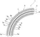
図1は、本発明の参考例1に係る可撓部材の屈曲構造体を示す断面図、図2は、同一部を示す拡大図である。 [Structure of bent structure]
FIG. 1 is a cross-sectional view showing a bent structure of a flexible member according to afirst embodiment of the present invention, and FIG. 2 is an enlarged view showing the same portion.
屈曲構造体1は、例えば各種分野のロボット、マニピュレーター、或はアクチュエータ等の関節機能部に適用されるものである。この屈曲構造体1は、関節機能部の基部及び可動部間に設けられ、屈曲により基部に対して可動部を変位可能に支持する。The
本参考例の屈曲構造体1は、二重コイル形状であり、外コイル部5と、内コイル部7とを備えている。この二重コイル形状により、本参考例の屈曲構造体1は、軸方向に対して屈曲可能であって、外力により屈曲する際に屈曲の内径側が収縮しかつ屈曲の外径側が伸長することにより、中心軸又は軸心Oの軸方向長さが屈曲前後及び屈曲中においてほぼ一定であり、非屈曲の際に軸方向への圧縮を規制する構成となっている。かかる本参考例の屈曲構造体1は、規制部材としての可撓部材3も備えている。
The
可撓部材3は、屈曲構造体1を軸方向に移動可能に挿通し、詳細は後述するが、内外コイル部5,7の径方向へのずれを規制するものである。本参考例の可撓部材3は、例えば、プッシュプルケーブル等を利用して構成されている。これに応じて、屈曲構造体1は、可撓部材3を軸方向へガイドする機能も有し、関節機能部の屈曲動作に応じて可撓部材3と共に屈曲可能となっている。 The
なお、屈曲とは、関節機能部又は屈曲構造体1の軸心Oを湾曲又は屈曲させることを意味する。また、可撓部材3は、省略することも可能である。Note that bending means curving or bending the axis O of the joint function part or
外コイル部5は、コイルばねであり、コイル状に巻かれた線材5aからなる。従って、外コイル部5は、軸方向に複数の巻部5bを有する。なお、巻部5bは、コイル形状を構成する一巻きを意味する(以下、同じ。)。The
線材5aの材質は、金属や樹脂等とすることが可能である。線材5aの断面は、円形に形成されているが、楕円等としてもよい。The material of the
外コイル部5の中心径D1は、軸方向の一端から他端に至るまで一定となっている。ただし、外コイル部5の中心径D1は、軸方向で変化させることも可能である。The central diameter D1 of the
外コイル部5は、軸方向で隣接する巻部5b間を軸方向で離間させた複数の隙間5cを有している。本参考例の隙間5cは、軸方向で隣接する巻部5bの各間に形成され、全ての隙間5cは、同一の軸方向の寸法を有している。ただし、隙間5cは、軸方向で一部の巻部5b間にのみ設けることも可能である。また、隙間5cの軸方向の寸法を変化させることも可能である。 The
内コイル部7は、コイルばねであり、軸方向に複数の巻部7bを有するコイル状に巻かれた線材7aからなる。内コイル部7は、外コイル部と同様、線材7aの材質を金属や樹脂とすることが可能であり、線材7aの断面が円形であるが、楕円等とすることも可能である。The
この内コイル部7は、外コイル部5の内側に位置し、内周に可撓部材3を挿通するための挿通部9が区画されている。本参考例の内コイル部7は、外コイル部5内に螺合されている。この螺合により、内コイル部7の巻部7bが外コイル部5の隣接する巻部5bの各間に位置している。従って、内コイル部7は、巻部7bが外コイル部5の隙間5cに対応して設けられた構成となっている。 The
また、内コイル部7の巻部7bは、中心径D2及び線材7aの線径d2の設定により、外コイル部5の隣接する巻部5bに接触しつつ当該巻部5b間に嵌合している。In addition, the winding
なお、内コイル部7の中心径D2は、軸方向の一端から他端に至るまで一定となっている。ただし、内コイル部7の中心径D2は、外コイル部5の中心径D1に応じて、軸方向で変化させること等も可能である。The central diameter D2 of the
また、線材7aの線径d2は、外コイル部5の線材5aの線径d1と同一になっている。ただし、線材7aの線径d2は、外コイル部5の線材5aの線径d1よりも大きく又は小さく形成してもよい。The wire diameter d2 of the
内コイル部7は、隣接する巻部7b間を軸方向で離間させた複数の隙間7cを有している。隙間7cは、外コイル部5との螺合に応じ、隣接する巻部7bの各間に形成され、全ての隙間7cは、同一の軸方向の寸法を有している。The
なお、外コイル部5及び内コイル部7は、外コイル部5内に内コイル部7が位置していない自由状態で、隣接する巻部5b,7bの各間に隙間5c,7cを有する構成の他、自由状態で隣接する巻部5b,7bが密着した構成(密着ばね)とすることも可能である。さらに、外コイル部5及び内コイル部7の一方のみを密着ばねとすることも可能である。In addition, the
外コイル部5及び内コイル部7が自由状態で密着ばねである場合は、内コイル部7と外コイル部5とを螺合することにより相互に巻部5b,7b間を離間させ、外コイル部5の隙間5c及び内コイル部7の隙間7cが形成される。この場合、二重コイル形状の屈曲構造体1に初張力を付与することが可能である。When the
[屈曲構造体の動作]
図3は、図1の屈曲構造体の屈曲状態を示す断面図、図4は、同一部を示す拡大図である。 [Operation of bending structure]
FIG. 3 is a cross-sectional view showing the bent state of the bent structure of FIG. 1, and FIG. 4 is an enlarged view showing the same portion.
屈曲構造体1は、図1及び図2のように、軸心O(外コイル部5の軸心でもある)が屈曲していない直状時に、内コイル部7の巻部7bが外コイル部5の隣接する巻部5bに接触しつつそれら隣接する巻部5b間に嵌合している。When the axis O (which is also the axis of the outer coil section 5) of the
このため、屈曲構造体1は、軸方向での圧縮力が作用しても、外コイル部5の隙間5cが圧縮されることを内コイル部7の巻部7bが規制し、全体としての圧縮が抑制される。なお、内コイル部7を基準にすると、内コイル部7の隙間7cが圧縮されるのを外コイル部5の巻部5bが規制することになる。Therefore, even if a compressive force acts in the axial direction on the
従って、屈曲構造体1は、自身の圧縮ひいては適用される関節機能部の圧縮を抑制することができる。この結果、可撓部材3の軸方向への移動をガイドする際に、軸心Oの長さ並びに軸心O上を通る可撓部材3の移動量を一定に保つことができ、可撓部材3の動作の安定性を確保することもできる。Therefore, the bending
図3及び図4のように、屈曲構造体1の軸心Oが屈曲すると、屈曲の内側で外コイル部5の隙間5cが小さくなり、屈曲の外側で外コイル部5の隙間5cが大きくなる。As shown in Figures 3 and 4, when the axis O of the
このとき、屈曲構造体1は、内コイル部7が径方向の外側に変位することにより屈曲を円滑に行うことができる。At this time, the bending
すなわち、内コイル部7の各巻部7bは、屈曲構造体1の屈曲の内側で、外コイル部5の隙間5cが小さくなることにより径方向の内側に押し込められる。これに応じ、内コイル部7は、全体として径方向の外側に変位するが、この変位は、内コイル部7の各巻部7bが外コイル部5の大きくなった隙間5cに入り込むようにして許容される。That is, each winding 7b of the
従って、屈曲構造体1は、軸方向の圧縮を規制することができる構成でありながら、可撓性が阻害されることはない。結果として、屈曲構造体1は、屈曲動作の安定化が図られる。Therefore, the bending
また、屈曲構造体1が屈曲する際は、上記のように、屈曲の内側で外コイル部5の隙間5cが小さくなり、屈曲の外側で外コイル部5の隙間が大きくなるので、軸心O上で隙間5cの大きさが直状時と比較して変化しないことになる。In addition, when the
従って、屈曲構造体1は、直状時だけでなく屈曲時にも、軸心Oの長さ及び屈曲構造体1の軸心O上を通る可撓部材3の移動量を一定に保つことができ、可撓部材3の動作の安定性を確保することができる。Therefore, the bending
また、本参考例の屈曲構造体1は、所定角度に屈曲した際に、屈曲の内側で外コイル部5の隣接する巻部5bが接触する(図4参照)。 Furthermore, when the
従って、屈曲構造体1では、巻部5bが接触したときから、軸心O上の長さが大きくなり始める。このため、可撓部材3の移動量の変化により、関節機能部の操作者に所定角度以上に屈曲したことを通知することができる。Therefore, in the bending
かかる屈曲構造体1の屈曲動作時には、可撓部材3により内コイル部7の外コイル部5からの脱落が防止される。When the bending
すなわち、上記のように、屈曲構造体1の屈曲時には、内コイル部7の各巻部7bが外コイル部5の大きくなった隙間5cに入り込むようにして、内コイル部7が全体として径方向の外側に変位する。That is, as described above, when the bending
この変位(内コイル部7が外コイル部5の軸心Oに対して径方向に移動可能な可動長さ)は、(外コイル部の直径-内コイル部の直径)の半分以下となっている。なお、ここでの直径は、外コイル部7及び内コイル部5の中心径D1及びD2を意味する。ただし、直径は、外コイル部7及び内コイル部5の外径又は内径であってもよい。This displacement (the movable length that the
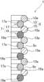
図5は、内コイル部7の外コイル部5からの脱落を示す概略断面図であり、(A)は脱落前、(B)は脱落後の状態である。Figure 5 is a schematic cross-sectional view showing the
図5のように、直状時に内コイル部7の径方向への移動量Lが(外コイル部5の直径-内コイル部7の直径)の半分(D1-D2)/2を超えると、内コイル部7が外コイル部5を乗り越えて脱落する状態となる。なお、図5において、移動量Lは、内コイル部7の軸心と外コイル部5の軸心とのズレ量として示している。As shown in Figure 5, when the radial movement amount L of the
屈曲構造体1の屈曲時においても、内コイル部7の径方向への移動量Lが(外コイル部5の直径-内コイル部7の直径)の半分(D1-D2)/2を超えると、直状に戻った際に図5のように脱落が生じてしまう結果になるため、本参考例では、内コイル部7が外コイル部5の軸心Oに対して径方向に移動可能な可動長さが、(外コイル部5の直径-内コイル部7の直径)の半分(D1-D2)/2以下となっている。 Even when the
この可動長さは、本参考例において、可撓部材3が屈曲構造体1を挿通することで設定されている。こうして、本参考例では、可撓部材3により内コイル部7の外コイル部5からの脱落が防止される。ただし、可動長さは、屈曲構造体1が可撓部材3を挿通しない場合や可撓部材3の径が上記可動長さを設定できない程度に細い場合、外コイル部5及び内コイル部7の線径d1及びd2の何れか一方又は双方の設定により設定することも可能である。 In thisreference example, this movable length is set by inserting the
[比較例の移動量]
図6(A)は、比較例に係る屈曲構造体を示す断面図、図6(B)は、同屈曲時を示す断面図である。 [Movement amount in comparative example]
FIG. 6A is a cross-sectional view showing a bent structure according to a comparative example, and FIG. 6B is a cross-sectional view showing the same when bent.
比較例に係る屈曲構造体1Aは、密着ばねのみからなっており、屈曲が可能であると共に圧縮が規制されるようになっている。The comparative bending structure 1A is made up of only a contact spring, and is capable of bending while restricting compression.
この屈曲構造体1Aでは、屈曲時に、屈曲の内側で巻部1Aaが接触した状態を維持し、屈曲の外側で巻部1Aa間に隙間が形成される。When this bent structure 1A is bent, the windings 1Aa remain in contact on the inside of the bend, and a gap is formed between the windings 1Aa on the outside of the bend.
この結果、屈曲時には、屈曲構造体1の屈曲内外の中央部でも巻部1Aa間に隙間1Abが形成される。その隙間1Abの分だけ、屈曲構造体1の軸心Oの長さ及び軸心O上を通る可撓部材3の移動量が大きくなる。As a result, when bending, a gap 1Ab is formed between the windings 1Aa even in the center inside and outside the bend of the bending
このため、比較例では、可撓部材3をガイドする際に、参考例1のように、可撓部材3の動作の安定性を確保することはできないものとなっている。 For this reason, in the comparative example, when guiding the
[参考例1の効果]
以上説明したように、本参考例の屈曲構造体1は、可撓部材3を軸方向に移動可能に挿通して、可撓部材3と共に屈曲可能な屈曲構造体であって、コイル状に巻かれて軸方向に複数の巻部5bを有する線材5aからなる外コイル部5と、コイル状に巻かれて軸方向に複数の巻部7bを有する線材7aからなり、外コイル部5内に位置する内コイル部7とを備える。 [Effects ofReference Example 1]
As described above, the bending
外コイル部5は、隣接する巻部5b間を離間させた複数の隙間5cを有し、内コイル部7は、巻部7bが外コイル部5の隙間5cに対応して設けられ、外コイル部5の隣接する巻部5bに接触しつつ、それら隣接する巻部5b間に嵌合する。The
従って、屈曲構造体1は、内コイル部7を外コイル部5内に位置させて構成されているため、構造を簡素化することができる。
Therefore, since the
また、屈曲構造体1は、軸方向での圧縮力が作用しても、外コイル部5の隙間5cが圧縮されることを内コイル部7の巻部7bが規制し、全体として圧縮が抑制される。このため、屈曲構造体1は、関節機能部を圧縮させない程度の軸方向の剛性を確保することができる。In addition, even if a compressive force acts in the axial direction on the bending
また、屈曲時には、屈曲の内側で外コイル部5の隙間5cを小さくしつつ屈曲の外側に内コイル部7を変位させ、屈曲の外側で外コイル部5の隙間を大きくして内コイル部7の変位を許容することで、軸方向の剛性を確保しても関節機能部と共に屈曲するための十分な可撓性を確保することができる。In addition, when bending, the
結果として、屈曲構造体1は、屈曲動作の安定化を図りつつ構造を簡素化することが可能となるため、ロボット、マニピュレーター、或はアクチュエータ等の関節機能部を有する機器の動作の安定性を確保することが可能となる。As a result, the bending
しかも、本参考例の屈曲構造体1は、屈曲の内側で外コイル部5の隙間5cが小さくなり、屈曲の外側で外コイル部5の隙間5cが大きくなるので、外コイル部5の軸心Oにおける長さが直状時と比較して変化せず、可撓部材3の移動量を確実に一定に保つことができる。 Moreover, in the
このため、可撓部材3の動作の安定性を確保することができ、ひいては関節機能部を有する機器の動作の安定性を、より確保することが可能となる。This ensures the stability of the operation of the
また、本参考例では、内コイル部7が外コイル部5の軸心Oに対して径方向に移動可能な可動長さ(変位量)が(外コイル部の直径-内コイル部の直径)の半分以下となっているので、内コイル部7が外コイル部5から脱落することを防止できる。 In addition, in thisreference example, the movable length (displacement amount) by which the
また、本参考例では、規制部材としての可撓部材3により、可動長さが(外コイル部の直径-内コイル部の直径)の半分以下となるように、内コイル部7の移動を規制するため、内コイル部7及び外コイル部5の形状を変更することなく、容易に内コイル部7の脱落を防止できる。 In addition, in thisreference example, the
屈曲構造体1は、可撓部材3を軸方向に移動可能に挿通して、可撓部材3と共に屈曲可能であるため、可撓部材3をガイドする態様において、可撓部材3を利用して内コイル部7の脱落を防止できる。The bending
本参考例では、外コイル部5が軸方向で隣接する巻部5bの各間に隙間5cを有したため、屈曲構造体1を円滑に屈曲させることができる。 In thisembodiment , the
本参考例では、内コイル部7と外コイル部5とが別体に形成され、内コイル部7が外コイル部5内に螺合されたため、組み付けが容易である。また、内コイル部7及び外コイル部5の何れか一方又は双方の特性を変更することにより、屈曲構造体1の特性を容易に変更することができる。 In thisreference example, the
また、本参考例の屈曲構造体1は、所定角度に屈曲した際に、屈曲の内側で外コイル部5の隣接する巻部5bが接触するので、可撓部材3の移動量の変化により、関節機能の操作者に所定角度以上に屈曲したことを通知することができる。 Furthermore, when the bending
図7は、参考例2に係る屈曲構造体の一部を示す拡大断面図である。なお、参考例2では、参考例1と対応する構成に同符号を付して重複した説明を省略する。 7 is an enlarged cross-sectional view showing a part of a bent structure according toReference Example 2. InReference Example 2, the same reference numerals are used to designate configurations corresponding to those inReference Example 1, and duplicated explanations will be omitted.
参考例2の屈曲構造体1は、外コイル部5の線材5aの線径d1と内コイル部7の線材7aの線径d2とを異ならせたものである。参考例2では、外コイル部5の線径d1を内コイル部7の線径d2よりも大きくしている。なお、外コイル部5の線径d1を内コイル部7の線径d2よりも小さくすることも可能である。In the
このように、屈曲構造体1は、外コイル部5の線径d1と内コイル部7の線径d2とを異ならせても、参考例1と同様の作用効果を奏することができる。また、線径d2と線径d1とを異ならせることにより、屈曲構造体1の自由長や特性を調整することができる。 In this way, even if the wire diameter d1 of the
図8は、参考例3に係る屈曲構造体の一部を示す拡大断面図である。なお、参考例3では、参考例1と対応する構成に同符号を付して重複した説明を省略する。 8 is an enlarged cross-sectional view showing a part of a bent structure according toReference Example 3. InReference Example 3, the same reference numerals are used to designate configurations corresponding to those inReference Example 1, and duplicated explanations will be omitted.
参考例3の屈曲構造体1は、外コイル部5の軸方向の一部において、内コイル部7の巻部7bが外コイル部5の隣接する巻部5bに接触しつつそれら隣接する巻部5b間に嵌合する。In the
すなわち、内コイル部7は、軸方向で漸次中心径D2(図1参照)が小さくなるように形成されている。これに応じて、内コイル部7は、上記のように、軸方向の一部でのみ外コイル部5の隣接する巻部5b間に嵌合している。That is, the
なお、本参考例では、内コイル部7及び外コイル部5がそれぞれ密着コイルであり、内コイル部7の中心径D2が小さくなるにつれて、外コイル部5の隙間5cが小さくなっている。 In thisembodiment , the
このように構成しても、参考例1と同様の作用効果を奏することができる。加えて、本参考例では、外コイル部5の軸方向の一部でのみ内コイル部7の巻部7bを外コイル部5の隣接する巻部5b間に嵌合させることにより、屈曲構造体1の自由長や特性を調整することができる。 Even with this configuration, it is possible to achieve the same effects as inReference Example 1. In addition, in thisReference Example, by fitting the winding
図9は、参考例4に係る屈曲構造体を示す断面図である。なお、参考例4では、参考例1と対応する構成に同符号を付して重複した説明を省略する。 9 is a cross-sectional view showing a bent structure according toReference Example 4. InReference Example 4, the same reference numerals are used to designate configurations corresponding to those inReference Example 1, and duplicated explanations will be omitted.
参考例4の屈曲構造体1は、軸方向の一部に漸次拡径する拡径部11を設けたものである。本参考例では、屈曲構造体1の軸方向の一端に拡径部11を設けている。ただし、拡径部11は、屈曲構造体1の軸方向の中間部や他端に設けることも可能である。The
拡径部11では、外コイル部5及び内コイル部7の中心径D1及びD2が共に漸次拡大し、且つ内コイル部7の巻部7bが外コイル部5の隣接する巻部5bに接触しつつ巻部5b間に嵌合する状態を維持している。In the
このように構成しても、参考例1と同様の作用効果を奏することができる。また、拡径部11により屈曲構造体1の特性を調整することができる。 Even with this configuration, it is possible to achieve the same effects as those ofReference Example 1. Furthermore, the characteristics of the
図10は、参考例5に係る屈曲構造体の一部を示す拡大断面図である。なお、参考例5では、参考例1と対応する構成に同符号を付して重複した説明を省略する。 10 is an enlarged cross-sectional view showing a part of a bent structure according toReference Example 5. InReference Example 5, the same reference numerals are used to designate configurations corresponding to those inReference Example 1, and duplicated explanations will be omitted.
参考例5の屈曲構造体1は、外コイル部5及び内コイル部7をそれぞれ二つのコイル部で構成したものである。具体的には、外コイル部5が第一外コイル部13及び第二外コイル部15で構成され、内コイル部7が第一内コイル部17及び第二内コイル部19で構成されている。In the
第一外コイル部13及び第二外コイル部15は、軸方向で交互に巻部13a,15aが位置し、第一内コイル部17及び第二内コイル部19も、軸方向で交互に巻部17a,19aが位置する。The first
すなわち、外コイル部5は、第一外コイル部13及び第二外コイル部15の巻部13a,15aが軸方向で隣接し、それら隣接する巻部13a,15a間に隙間5cが形成されている。That is, in the
内コイル部7の第一内コイル部17の巻部17a及び第二内コイル部19の巻部19aは、それぞれ第一外コイル部13及び第二外コイル部15の巻部13a,15aに接触しつつそれら巻部13a,15a間に嵌合している。The winding
このように構成しても、参考例1と同様の作用効果を奏することができ、且つ屈曲構造体1の特性や自由長を調整することができる。 Even with this configuration, the same effects as those of thefirst embodiment can be achieved, and the characteristics and free length of the
なお、外コイル部5及び内コイル部7を構成するコイル部の数は変更することが可能である。また、外コイル部5及び内コイル部7の一方のみを複数のコイル部で構成することも可能である。The number of coil parts constituting the
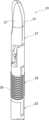
図11は、本発明の参考例6に係り、屈曲構造体を適用したロボット鉗子の一部を示す斜視図、図12は、同断面図、図13は、図11のロボット鉗子の関節機能部を示す斜視図、図14は、同断面図である。なお、参考例6では、参考例1と対応する構成に同符号を付して重複した説明を省略する。 Fig. 11 is a perspective view showing a part of a robot forceps to which a bending structure is applied according toa sixth embodiment of the present invention, Fig. 12 is a cross-sectional view of the same, Fig. 13 is a perspective view showing a joint function part of the robot forceps in Fig. 11, and Fig. 14 is a cross-sectional view of the same. Note that in the sixthembodiment , the same reference numerals are used to designate components corresponding to those inthe first embodiment, and duplicated explanations will be omitted.
本参考例のロボット鉗子21は、医療用マニピュレーターである手術ロボットのロボットアーム先端を構成するものである。 The
なお、ロボット鉗子21は、関節機能部を有する機器の一例である。関節機能部を有する機器は、上記のとおり医療用マニピュレーターに限られるものではない。すなわち、関節機能部を有する機器としては、屈曲動作を行う関節機能部を有し、且つ可撓部材3を軸方向に移動させて動作等を行うものであれば、他の分野のロボット、各種のマニピュレーター、或はアクチュエータ等、特に限定されるものではない。また、医療用マニピュレーターの場合は、手術ロボットに取り付けない内視鏡カメラや手動鉗子等も含まれる。The
本参考例のロボット鉗子21は、シャフト23、関節機能部25、外科手術用のエンドエフェクタとしての把持ユニット27によって構成されている。 The
シャフト23は、例えば円筒形状に形成されている。シャフト23内には、関節機能部25を駆動するための駆動ワイヤ29や把持ユニット27を駆動するためのプッシュプルケーブルからなる可撓部材3が通っている。シャフト23の先端側には、関節機能部25を介して把持ユニット27が設けられている。The
関節機能部25は、基部31と、可動部33と、可撓チューブ35と、屈曲構造体1とを備えている。The
基部31は、樹脂や金属等によって形成された円柱体であり、シャフト23の先端に取り付けられている。基部31には、貫通孔31aにより駆動ワイヤ29が軸方向に挿通し、軸心部の挿通孔31bにより可撓部材3を挿通している。The
可動部33は、樹脂や金属等によって形成された円柱体であり、後述する把持ユニット27に取り付けられている。可動部33には、駆動ワイヤ29の先端部が固定されている。このため、可動部33は、駆動ワイヤ29の操作により、基部31に対して変位し、把持ユニット27を所望の方向に指向させる。可動部33の軸心部には、挿通孔33bが設けられ、可撓部材3を挿通している。The
可撓チューブ35は、基部31と可動部33との間に介設され、基部31に対する可動部33の変位に応じて屈曲する。可撓チューブ35は、駆動ワイヤ29及び可撓部材3を軸方向に通している。The
本参考例の可撓チューブ35は、断面波形状の管体からなるベローズによって構成されている。ただし、可撓チューブ35は、コイルばね、筒体等を用いることも可能であり、可撓性を有するチューブ状を呈していれば、特に限定されるものではない。 The
屈曲構造体1は、参考例1と同一構成である。この屈曲構造体1は、可撓チューブ35の軸心部に沿って配置され、基部31と可動部33との間に設けられている。なお、関節機能部25には、参考例2~5の何れかの屈曲構造体1を適用することも可能である。 The bending
屈曲構造体1は、挿通部9に可撓部材3を挿通した状態で、両端が基部31及び可動部33の挿通孔31b及び33bにそれぞれ取り付けられている。これにより、屈曲構造体1は、基部31に対して可動部33を軸方向移動不能に支持し、基部31に対する可動部33の変位に応じて可撓部材3と共に屈曲するようになっている。With the
把持ユニット27は、関節機能部25の可動部33に対し、一対の把持部37が開閉可能に軸支されている。この把持ユニット27は、関節機能部25を貫通した可撓部材3が接続され、可撓部材3の軸方向移動(進退動作)により、把持部37が開閉するように構成されている。なお、エンドエフェクタとしては、把持ユニット27に限られず、例えば、鋏、把持レトラクタ、及び針ドライバ等とすることも可能である。The gripping
かかる構成のロボット鉗子21では、医師等の操作者が可撓部材3を進退させることにより把持ユニット27の把持部37に開閉動作を行わせることができる。In a
また、操作者が何れか一つ或は複数の駆動ワイヤ29を引くことにより、関節機能部25が屈曲してシャフト23に対して把持ユニット27を所望の方向に指向させることができる。この状態で、可撓部材3を進退させれば、把持ユニット27の把持部37に開閉動作を行わせることができる。In addition, when the operator pulls one or more of the
かかる開閉動作は、参考例1で説明したように、可撓部材3の移動量が一定であるため、安定して正確に行わせることができる。 As described inthe first embodiment, this opening and closing operation can be performed stably and accurately because the amount of movement of the
その他、本参考例では、参考例1と同様の作用効果を奏することができる。 In addition, thisembodiment can achieve the same effects as thoseof the first embodiment.
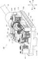
図15は、本発明の実施例1に係り、屈曲構造体を適用した手術支援ロボット用インスツルメントを示す概略斜視図である。なお、実施例1では、参考例1及び6と対応する構成に同符号を付して重複した説明を省略する。 15 is a schematic perspective view showing an instrument for a surgical support robot to which a bending structure is applied according to thefirst embodiment of the present invention. Note that in thefirst embodiment, the samereference numerals are used to designate configurations corresponding to those in the first and sixth embodiments, and duplicated explanations will be omitted.
本実施例は、参考例1の屈曲構造体1を適用した手術支援ロボット用インスツルメント100である。ただし、手術支援ロボット用インスツルメント100は、参考例2~5の何れかの屈曲構造体1を適用することも可能である。この手術支援ロボット用インスツルメント100は、マスタースレーブ型の手術ロボットに交換可能なものとして取り付けられ、手術ロボットからの駆動力によって駆動される。なお、本実施例の手術支援ロボット用インスツルメント100は、参考例6のロボット鉗子21を交換可能なユニットとしたものに相当する。 This embodiment is an
この手術支援ロボット用インスツルメント100は、図15のように、本体110と、シャフト23と、外科手術用の把持ユニット27と、関節機能部25とを備えている。As shown in FIG. 15, this
なお、本実施例では説明を容易にするために、シャフト23における軸線Lの方向(軸方向)を前後方向とし、前後方向と直交する方向であって後述する一対の本体側プーリ131L,131Rが並んで配置される方向を左右方向とし、前後方向及び左右方向に直交する方向を上下方向として説明する(図16参照)。For ease of explanation, in this embodiment, the direction of the axis L of the shaft 23 (axial direction) is defined as the front-rear direction, the direction perpendicular to the front-rear direction in which a pair of main body side pulleys 131L, 131R (described later) are arranged side by side is defined as the left-right direction, and the direction perpendicular to the front-rear direction and left-right direction is defined as the up-down direction (see FIG. 16).
本体110は、手術支援ロボット用インスツルメント100の基部を構成するものである。本体110には、棒状の部材、特に円筒状の部材であるシャフト23が前後方向に沿って延びている。The
シャフト23の前後方向(軸方向)の先端部には、外科手術用のエンドエフェクタとして把持ユニット27が設けられている。なお、エンドエフェクタとしては、参考例6と同様、把持ユニット27に限られず、例えば、鋏、把持レトラクタ、及び針ドライバ等とすることも可能である。また、シャフト23の先端部には、関節機能部25が設けられている。関節機能部25は、屈曲構造体1を有し、前後方向に対して屈曲することにより、把持ユニット27の向きを変更可能とする。 A gripping
以下、本体110の一例について図16及び図17をも参照して詳細に説明する。なお、本体110は、図16及び図17に示す形態に限定されるものではなく、他の形態を採用することも可能である。また、シャフト23、把持ユニット27、及び関節機能部25は、参考例6と同一構成であるため、詳細については参考例6を参照することにより説明を省略する。 An example of the
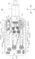
図16は、手術支援ロボット用インスツルメント100の本体110の内部構成の一例を示す斜視図、図17は、同平面図である。Figure 16 is a perspective view showing an example of the internal configuration of the
本体110は、内部にシャフト側プーリ121、一対の本体側プーリ131L,131R、駆動プーリ132、鉗子用プーリ141、ガイドプーリ142、可動部151等を収納する直方体状に形成されたものである。The
なお、図15では、本体110の内部に配置されたシャフト側プーリ121、一対の本体側プーリ131L,131R、駆動プーリ132、鉗子用プーリ141、ガイドプーリ142、可動部151等を説明するために、本体110の基板111及び天板115のみを図示し、周囲を覆う部材等は図示を省略している。図16では、さらに天板115の図示も省略している。In FIG. 15, in order to explain the shaft-
本体110の基板111は、前方向の端辺の中央においてシャフト23及びシャフト側プーリ121を軸線Lまわりに回転可能に支持するものである。また、基板111の上方向の面に、本体側プーリ131、駆動プーリ132、鉗子用プーリ141及びガイドプーリ142が回転可能に配置されるものである。The
さらに、基板111には前後方向に延びる長孔状に形成された4つのスリット112が、左右方向に間隔を開けて並んで設けられている。当該4つのスリット112には、それぞれ1つの可動部151が基板111に対して前後方向に相対移動可能に配置されている。Furthermore, four
4つのスリット112は、右側から左側に向かってスリット112A、スリット112B、スリット112C、スリット112Dである。スリット112Aは、他のスリット112B、スリット112C及びスリット112Dよりも前後方向に長く形成されている。また、スリット112B、スリット112C及びスリット112Dは、前後方向の長さが等しく形成されている。The four
天板115は、基板111から上方向に延びる支柱113に取り付けられる板状部材である。天板115は、基板111との間に本体側プーリ131L,131R、駆動プーリ132、鉗子用プーリ141及びガイドプーリ142を挟んで支持すると共に、本体側プーリ131L,131R、駆動プーリ132、鉗子用プーリ141及びガイドプーリ142を回転可能に支持するものである。The
シャフト23は、本体110から前方向に向かって延びる円筒状の部材であって、本体110に対して軸線Lまわりに回転可能に支持されたものである。シャフト23の後方向の基端部には、シャフト23と軸線Lを共有するシャフト側プーリ121が設けられている。本実施例では、シャフト23の前方向の先端部に鉗子(把持ユニット27)が設けられている例に適用して説明する。The
シャフト側プーリ121は、シャフト23における後方向(本体110側)の基端部に、シャフト23と共に本体110に対して回転可能に設けられる円筒状に形成された部材である。また、シャフト側プーリ121の外周面には、シャフト23の回転を制御する回転用ワイヤ(索状体)122が巻き付けられるらせん状の溝が形成されている。The shaft-
一対の本体側プーリ131L,131Rは、本体110の基板111におけるシャフト側プーリ121を間に挟む左右方向の位置に、本体110に対して回転可能に配置されるものである。本体側プーリ131L,131Rは、円板状または円柱状に形成され、その外周面には、回転用ワイヤ122が巻き付けられる円環状の溝が形成されているものである。なお、本体側プーリ131Lは左側に配置されるものであり、本体側プーリ131Rは右側に配置されるものである。The pair of main body side pulleys 131L, 131R are arranged rotatably relative to the
回転用ワイヤ122は、本体側プーリ131Rの回転をシャフト側プーリ121及びシャフト23に伝達する索状に形成されたものである。また、回転用ワイヤ122は、一対の本体側プーリ131L,131Rの間に環状に配置されると共に、シャフト側プーリ121の外周面に巻き付けられて配置されるものである。The
駆動プーリ132は、本体110の基板111における本体側プーリ131Rの後方向に配置されたプーリである。駆動プーリ132は、円板状または円柱状に形成され、その外周面には、伝達用ワイヤ(他の索状体)133が巻き付けられる円環状の溝が形成されているものである。The
駆動プーリ132と本体側プーリ131Rとの間には、シャフト23の回転駆動に用いられるスリット112Aが設けられ、当該スリット112Aにはシャフト23の回転駆動に用いられる可動部151Aが配置されている。A
伝達用ワイヤ133は、本体110の基板111に対する可動部151Aの前後方向への相対移動を、本体側プーリ131Rに伝達する索状に形成されたものである。また、伝達用ワイヤ133は、駆動プーリ132と本体側プーリ131Rとの間に環状に配置されると共に、その一部が可動部151Aに固定して取り付けられているものである。The
鉗子用プーリ141は、本体110の基板111における軸線Lの近傍であって、後方向に配置されたプーリである。鉗子用プーリ141は、円板状または円柱状に形成され、その外周面には、鉗子用ワイヤ143が巻き付けられる円環状の溝が形成されているものである。The
鉗子用プーリ141とシャフト側プーリ121との間には、ガイドプーリ142及びスリット112B及びスリット112Cが配置されている。スリット112Cには鉗子の駆動に用いられる可動部151Cが配置されている。A
ガイドプーリ142は、鉗子用ワイヤ143を本体110側からシャフト側プーリ121及びシャフト123の内部へ導くプーリである。本実施例では、4つのガイドプーリ142が、本体110の基板111におけるスリット112B及びスリット112Cと、シャフト側プーリ121との間に配置される例に適用して説明する。ガイドプーリ142は、円板状または円柱状に形成され、その外周面には、鉗子用ワイヤ143がかけられる円環状の溝が形成されている。The
ガイドプーリ142の数は4つであってもよいし、4つよりも多くても少なくてもよい。また、複数のガイドプーリ142の相対的な配置関係も、鉗子用ワイヤ143をシャフト側プーリ121及びシャフト23の内部へ導く配置関係であればよく、特に限定するものではない。The number of guide pulleys 142 may be four, or may be more or less than four. In addition, the relative positional relationship of the multiple guide pulleys 142 is not particularly limited as long as it guides the
鉗子用ワイヤ143は、本体110の基板111に対する可動部151Cの前後方向への相対移動を、シャフト23における前方向の端部に配置された鉗子に伝達する索状に形成されたものである。また、鉗子用ワイヤ143は、鉗子用プーリ141と鉗子(把持ユニット27)との間に環状に配置されると共に、その一部が可動部151Cに固定して取り付けられているものである。The
すなわち、鉗子用ワイヤ143は、参考例6の駆動ワイヤ29に相当し、関節機能部25の可動部33に先端部が固定され、可撓チューブ35及び基部31を挿通し、シャフト23内を通って本体110へと引き出されている。そして、鉗子用ワイヤ143の基端部は、ガイドプーリ142を経由して鉗子用プーリ141に結合されて一体に構成されている。このように、鉗子用ワイヤ143は、関節機能部25の可動部33及び鉗子用プーリ141を介して環状に構成されている。 That is, the
なお、本実施例では、鉗子用ワイヤ143が可動部151Cに固定して取り付けられている例に適用して説明するが、鉗子用ワイヤ143が可動部151Bや151Dに固定して取り付けられていてもよく、特に限定するものではない。本実施例において、可動部151Bや可動部151Dの一方は、例えば関節機能部25を異なる方向に屈曲させる鉗子用ワイヤに結合し、他方は、例えば把持ユニット27を開閉する鉗子ワイヤやプッシュプルケーブル等の可撓部材に結合してもよい。In this embodiment, the
可動部151は、本体110の基板111に設けられた4つのスリット112のそれぞれに配置されるものであって、本体110の基板111に対してスリット112に沿って前後方向に相対移動可能に配置されるものである。可動部151は、手術支援ロボット用インスツルメント100が取り付けられるマスタースレーブ型の手術ロボットから伝達される駆動力によって、移動されるものである。The
4つのスリット112のうち、スリット112Aに可動部151Aが配置され、スリット112Bに可動部151Bが配置され、スリット112Cに可動部151Cが配置され、スリット112Dに可動部151Dが配置されている。Of the four
次に、上記の構成からなる手術支援ロボット用インスツルメント100における動作について説明する。まず、シャフト23を回転させる動作について説明し、次いで関節機能部25を屈曲させる動作について説明する。Next, the operation of the surgical
シャフト23を回転させる場合には、可動部151Aをスリット112Aに沿って前方向または後方向へ移動させる駆動力が外部から加えられる。例えば、可動部151Aが前方向へ移動すると、伝達用ワイヤ133における可動部151Aに取り付けられた部分も前方向へ移動する。When rotating the
環状の伝達用ワイヤ133は上方向から見て左回りに回転する方向に移動する。この伝達用ワイヤ133の動きにより、本体側プーリ131Rは左回りに回転される。本体側プーリ131Rの左回りの回転は、本体側プーリ131Rに巻き付けられた回転用ワイヤ122に伝達される。The
回転用ワイヤ122は左回りに回転され、回転用ワイヤ122の動きがシャフト側プーリ121に伝達され、シャフト側プーリ121は軸線Lまわりに回転される。シャフト側プーリ121の回転方向は、シャフト側プーリ121への回転用ワイヤ122の巻き付け方向に基づいて決まる。可動部151Aが後方向へ移動した場合には、上述とは逆方向への動きとなる。The
次に、関節機能部25を屈曲させるように駆動する場合には、可動部151Cをスリット112Cに沿って前方向または後方向へ移動させる駆動力が外部から加えられる。例えば、可動部151Cが前方向へ移動すると、鉗子用ワイヤ143における可動部151Cに取り付けられた部分も前方向へ移動する。Next, when driving the
環状の鉗子用ワイヤ143は上方向から見て右回りに回転する方向に移動する。この鉗子用ワイヤ143の動きが把持ユニット27の可動部33に伝達され、関節機能部25が屈曲するように駆動される。The ring-shaped
上記の構成の手術支援ロボット用インスツルメント100によれば、参考例1及び6と同様の作用効果を奏することができる。加えて、シャフト23に配置されたシャフト側プーリ121を挟んで一対の本体側プーリ131L,131Rが配置され、シャフト側プーリ121、及び、一対の本体側プーリ131L,131Rに回転用ワイヤ122が巻き付けられている。この回転用ワイヤ122に駆動力を伝達することによりシャフト側プーリ121及びシャフト23が回転される。 The surgical
一対の本体側プーリ131L,131Rの間にシャフト側プーリ121を配置し、一方の本体側プーリ131Rから延びる回転用ワイヤ122をシャフト側プーリ121に巻き付け、その後、回転用ワイヤ122を他方の本体側プーリ131Lに巻き付けている。そのため、シャフト側プーリ121及びシャフト123に対して、シャフト123の軸線方向に対する垂直方向(言い換えるとラジアル方向)に力が働くことを抑制しやすくなる。その結果としてシャフト23を回転させる駆動負荷を小さくしやすくなる。The
また、シャフト側プーリ121における回転用ワイヤ122が巻き付けられる部分の面積を小さくしやすくなる、言い換えると、シャフト側プーリ121における軸線方向の長さを短くしやすくなる。In addition, it becomes easier to reduce the area of the shaft-
直線方向への可動部151Aの動きを、伝達用ワイヤ133を介して本体側プーリ131に伝えることにより、可動部151Aの直動移動を、シャフト123の回転移動に変換する際に発生する損失を抑制しやすくなる。By transmitting the linear movement of the
並んで配置された複数の可動部151A,151B,151C,151Dのうち、端部に配置された可動部151Aに伝達用ワイヤ133を取りつけることにより、内側に配置された可動部151B,151Cに伝達用ワイヤ133を取りつける場合と比較して、手術支援ロボット用インスツルメント100のコンパクト化を図りやすくなる。By attaching the
図18は、本発明の実施例2に係り、手術支援ロボット用インスツルメントの本体の内部構成を示す平面図、図19は、図18の手術支援ロボット用インスツルメントの本体の内部構成を説明する部分斜視図である。本実施例の手術支援ロボット用インスツルメント100の基本構成は、実施例1と同様であるが、実施例1とは一対の本体側プーリに関する構成が異なっている。よって、本実施例においては、図18及び図19を用いて一対の本体側プーリに関する構成について説明し、その他の構成等の説明を省略する。 Fig. 18 is a plan view showing the internal configuration of a main body of an instrument for a surgical support robot according to asecond embodiment of the present invention, and Fig. 19 is a partial perspective view explaining the internal configuration of the main body of the instrument for a surgical support robot of Fig. 18. The basic configuration of the instrument for a
本実施例の手術支援ロボット用インスツルメント100における本体110の基板111には、図18及び図19に示すように、調整部114が設けられている。調整部114は、本体側プーリ131Lを回転可能に支持するものであり、かつ、基板111に対して本体側プーリ131Lを左右方向へ相対移動可能に支持するものである。As shown in Figures 18 and 19, the
言い換えると、本体側プーリ131Rに対して本体側プーリ131Lを接近離間可能に支持するものである。調整部114には、左右方向に延びる長孔117が設けられている。調整部114は、長孔117に挿通されるネジ等の固定部材116によって基板111に取り付けられている。In other words, it supports the main
また、本実施例の手術支援ロボット用インスツルメント100の本体側プーリ131Rには、相対的に径が大きな大径プーリ部134a、および、相対的に径が小さな小径プーリ部134bが設けられている。大径プーリ部134aは、本体側プーリ131Rの上方向側に設けられ、小径プーリ部134bは、本体側プーリ131Rの下方向側に設けられている。The main
大径プーリ部134aには、回転用ワイヤ122が巻き付けられる円環状の溝が形成され、小径プーリ部134bには、伝達用ワイヤ133が巻き付けられる円環状の溝が形成されている。The large
本実施例では、本体側プーリ131Rにおける回転用ワイヤ122が巻き付けられる部分の径が相対的に大きく、伝達用ワイヤ133が巻き付けられる部分の径が相対的に小さい例に適用して説明したが、回転用ワイヤ122が巻き付けられる部分の径が相対的に小さく、伝達用ワイヤ133が巻き付けられる部分の径が相対的に大きくてもよい。In this embodiment, the description is given of an example in which the diameter of the portion of the
上記の構成からなる手術支援ロボット用インスツルメント100においては、実施例1と同様の作用効果を奏することができる。加えて、図18及び図19に示すように、固定部材116を緩めることにより、基板111に対して調整部114を左右方向に移動させることにより、本体側プーリ131Lと本体側プーリ131Rとの間の間隔が調整される。言い換えると、回転用ワイヤ122の張力が所望の張力となるように調整される。調整後に固定部材116を締め直すことにより、基板111に対して調整部114が固定され、本体側プーリ131Lと本体側プーリ131Rとの間の間隔が固定される。 The
また、可動部151Aをスリット112Aに沿って前方向または後方向へ移動させる駆動力が外部から加えられると、伝達用ワイヤ133は回転移動する。この伝達用ワイヤ133の動きにより、本体側プーリ131Rも回転して回転用ワイヤ122に伝達される。When a driving force is applied from the outside to move the
この時、伝達用ワイヤ133が巻き付けられる小径プーリ部134bと、回転用ワイヤ122が巻き付けられる大径プーリ部134aおよびの径の比率に従って、伝達用ワイヤ133の移動量が増幅されて回転用ワイヤ122に伝達される。At this time, the amount of movement of the
なお、本実施例では伝達用ワイヤ133の移動量が増幅されて回転用ワイヤ122に伝達される例に適用して説明したが、伝達用ワイヤ133が巻き付けられるプーリ部の径と、回転用ワイヤ122が巻き付けられるプーリ部の径との比率を変えることにより、本実施例では伝達用ワイヤ133の移動量が減少されて回転用ワイヤ122に伝達される場合もある。In this embodiment, the amount of movement of the
上記の構成によれば、一対の本体側プーリ131L,131Rの間隔が調整可能とされることにより、一対の本体側プーリ131L,131Rの間に掛け回される回転用ワイヤ122に働く張力(テンション)の調整が容易になる。さらに、張力の調整が容易になることから、手術支援ロボット用インスツルメント100を組み立てる際のバラツキの発生を抑えやすくなる。また、外力推定の精度を高めやすくなる。According to the above configuration, the distance between the pair of main body side pulleys 131L, 131R is adjustable, which makes it easy to adjust the tension acting on the
このように大径プーリ部134aに回転用ワイヤ122を巻き付け、小径プーリ部134bに伝達用ワイヤ133を巻き付けることにより、可動部151Aの直線方向への移動量と、シャフト23の回転量との比率を所望の値に調整しやすくなる。By winding the
なお、本発明の技術範囲は上記実施例に限定されるものではなく、本発明の趣旨を逸脱しない範囲において種々の変更を加えることが可能である。例えば、本発明を上記の実施例に適用したものに限られることなく、これらの実施例を適宜組み合わせた実施例に適用してもよく、特に限定するものではない。The technical scope of the present invention is not limited to the above examples, and various modifications can be made without departing from the spirit of the present invention. For example, the present invention is not limited to the above examples, but may be applied to examples that combine these examples appropriately, and is not particularly limited.
1屈曲構造体 3可撓部材 5外コイル部 5a,7a線材 5b,7b巻部 5c隙間 7内コイル部 25関節機能部 27把持ユニット(エンドエフェクタ) 31基部 33可動部 35可撓チューブ 100 手術支援ロボット用インスツルメント1
Claims (10)
Translated fromJapanese前記本体から延びる棒状の部材であるシャフトと、
前記シャフトの軸方向の先端部に設けられた外科手術用のエンドエフェクタと、
前記先端部に設けられ前記シャフトの軸方向に対して屈曲することで前記エンドエフェクタの向きを変更可能とする関節機能部とを備え、
前記関節機能部は、前記屈曲を可能とする屈曲構造体を有し、
前記屈曲構造体は、
前記エンドエフェクタに接続されて前記軸方向に移動可能に挿通した可撓部材と共に前記軸方向に対して屈曲可能であり、前記可撓部材の前記軸方向への移動をガイドする機能を有し、
コイル状に巻かれて前記軸方向に複数の巻部を有する線材からなるコイルばねである外コイル部と、
コイル状に巻かれて前記軸方向に複数の巻部を有する線材からなり前記外コイル部内に位置するコイルばねである内コイル部と、
前記可撓部材とを備え、
前記外コイル部は、前記軸方向で隣接する巻部間を離間させた複数の隙間を有し、
前記内コイル部は、前記巻部が前記外コイル部の前記隙間に対応して設けられ前記外コイル部の前記隣接する巻部に接触しつつ当該巻部間に嵌合し、
前記内コイル部は、前記可撓部材の外周が径方向で直接対向する内周により前記可撓部材を挿通してガイドする挿通部を区画し、
前記可撓部材は、前記内コイル部及び前記外コイル部の屈曲した状態において該屈曲の状態を変更せずに前記挿通部内を前記軸方向に移動可能である、
ことを特徴とする手術支援ロボット用インスツルメント。
The main body,
A shaft that is a rod-shaped member extending from the main body;
a surgical end effector provided at a distal end of the shaft in an axial direction;
a joint function unit provided at the tip portion and configured to bend in an axial direction of the shaft to change the orientation of the end effector,
The joint function portion has a bending structure that enables the bending,
The bending structure is
a flexible member that is connected to the end effector and is inserted therethrough so as to be movable in the axial direction, and has a function of guiding the movement of the flexible member in the axial direction;
an outer coil portion which is a coil spring made of a wire wound in a coil shape and having a plurality of windings in the axial direction;
an inner coil portion which is a coil spring located within the outer coil portion and which is made of a wire wound in a coil shape and has a plurality of windings in the axial direction;
The flexible member ,
The outer coil portion has a plurality of gaps separating adjacent winding portions in the axial direction,
The inner coil portion has a winding portion provided corresponding to the gap of the outer coil portion and fitted between the adjacent winding portions of the outer coil portion while contacting the adjacent winding portions,
the inner coil portion defines an insertion portion through which the flexible member is inserted and guided by an inner periphery of the inner coil portion, the outer periphery of the flexible member being directly opposed to the inner periphery of the inner coil portion in a radial direction;
the flexible member is movable in the axial direction within the insertion portion without changing the bent state of the inner coil portion and the outer coil portion when the inner coil portion and the outer coil portion are bent.
An instrument for a surgical assistance robot, characterized in that
前記外コイル部は、前記軸方向で隣接する巻部の各間に前記隙間を有した、
ことを特徴とする手術支援ロボット用インスツルメント。 2. The surgical robot instrument according to claim 1,
The outer coil portion has the gap between each of the winding portions adjacent to each other in the axial direction.
1. An instrument for a surgical assistance robot, comprising:
前記内コイル部が前記外コイル部の軸心に対して前記径方向に移動可能な可動長さは、(外コイル部の直径-内コイル部の直径)の半分以下である、
ことを特徴とする手術支援ロボット用インスツルメント。 3. The surgical robot instrument according to claim 1,
The movable length of the inner coil portion in the radial direction relative to the axis of the outer coil portion is equal to or less than half of (the diameter of the outer coil portion - the diameter of the inner coil portion).
1. An instrument for a surgical assistance robot, comprising:
前記可動長さが(外コイル部の直径-内コイル部の直径)の半分以下となるように、前記内コイル部の移動を規制する規制部材を有する、
ことを特徴とする手術支援ロボット用インスツルメント。 4. The surgical robot instrument according to claim 3,
A restricting member is provided for restricting the movement of the inner coil portion so that the movable length is equal to or less than half of (the diameter of the outer coil portion - the diameter of the inner coil portion).
1. An instrument for a surgical assistance robot, comprising:
前記規制部材は前記可撓部材である、
ことを特徴とする手術支援ロボット用インスツルメント。 5. The surgical robot instrument according to claim 4,
The regulating member is the flexible member.
1. An instrument for a surgical assistance robot, comprising:
前記内コイル部と前記外コイル部とが別体に形成され、前記内コイル部が前記外コイル部内に螺合された、
ことを特徴とする手術支援ロボット用インスツルメント。 The surgical robot instrument according to any one of claims 1 to 5,
The inner coil portion and the outer coil portion are formed separately, and the inner coil portion is screwed into the outer coil portion.
1. An instrument for a surgical assistance robot, comprising:
前記外コイル部は、所定角度に屈曲した際に、屈曲の内側で隣接する巻部が接触する、
ことを特徴とする手術支援ロボット用インスツルメント。 The surgical robot instrument according to any one of claims 1 to 6,
When the outer coil portion is bent at a predetermined angle, adjacent winding portions come into contact with each other on the inner side of the bend.
1. An instrument for a surgical assistance robot, comprising:
前記関節機能部は、前記シャフト側の基部及び前記エンドエフェクタを支持し前記基部に対して変位する可動部を備え、
前記屈曲構造体は、前記基部と前記可動部との間に設けられ、前記基部に対する前記可動部の変位に応じて屈曲する、
ことを特徴とする手術支援ロボット用インスツルメント。 The surgical support robot instrument according to any one of claims 1 to 7,
the joint function unit includes a base portion on the shaft side and a movable portion supporting the end effector and displacing relative to the base portion,
The bending structure is provided between the base and the movable part and bends in response to displacement of the movable part relative to the base.
1. An instrument for a surgical assistance robot, comprising:
前記基部及び先端部間に介設された前記軸方向に伸縮可能な可撓チューブを備え、
前記屈曲構造体は、前記可撓チューブの軸心部に沿って前記軸方向に配置された、
ことを特徴とする手術支援ロボット用インスツルメント。 9. The surgical robot instrument according to claim 8,
a flexible tube interposed between the base portion and the tip portion and capable of expanding and contracting in the axial direction;
The bending structure is arranged in the axial direction along the axial center portion of the flexible tube.
1. An instrument for a surgical assistance robot, comprising:
前記関節機能部は、
前記シャフト側の基部及び前記エンドエフェクタを支持し前記基部に対して変位する可動部と、
前記基部及び先端部間に介設されて前記軸方向に伸縮可能であり前記屈曲構造体の前記外コイル部の径方向外側に位置する可撓チューブとを備え、
前記屈曲構造体は、前記基部と前記可動部との間に設けられ、前記基部に対する前記可動部の変位に応じて屈曲し、
前記基部及び前記可動部は、それぞれ前記屈曲構造体に対して径方向外側に突出し、前記可撓チューブは、前記屈曲構造体に対する前記基部及び前記可動部の前記径方向外側に突出する部分間に介設された、
ことを特徴とする手術支援ロボット用インスツルメント。
The surgical robot instrument according to claim 1,
The joint function part includes:
a movable portion that supports the shaft-side base portion and the end effector and is displaceable relative to the base portion;
a flexible tube interposed between the base and the tip, expandable in the axial direction, and positioned radially outside the outer coil portion of the bending structure;
the bending structure is provided between the base and the movable part and bends in response to displacement of the movable part relative to the base,
The base portion and the movable portion each protrude radially outward relative to the bending structure, and the flexible tube is interposed between the radially outward protruding portions of the base portion and the movable portion relative to the bending structure.
1. An instrument for a surgical assistance robot, comprising:
Priority Applications (10)
| Application Number | Priority Date | Filing Date | Title |
|---|---|---|---|
| TW108127626ATWI720570B (en) | 2018-08-14 | 2019-08-02 | Curved structure and joint function part using the structure |
| CN201980052744.9ACN112566759A (en) | 2018-08-14 | 2019-08-02 | Bending structure and joint functional unit using same |
| CN201980053995.9ACN112654475A (en) | 2018-08-14 | 2019-08-02 | Instrument for surgical auxiliary robot |
| US17/268,891US20210307773A1 (en) | 2018-08-14 | 2019-08-02 | Instrument for surgical assistance robot |
| EP19850396.3AEP3838518A4 (en) | 2018-08-14 | 2019-08-02 | FLEXIBLE STRUCTURE AND JOINT FUNCTIONAL COMPONENT |
| PCT/JP2019/030573WO2020036081A1 (en) | 2018-08-14 | 2019-08-02 | Instrument for surgical assistance robot |
| US17/268,929US12262905B2 (en) | 2018-08-14 | 2019-08-02 | Bending structure and joint function part |
| PCT/JP2019/030599WO2020036085A1 (en) | 2018-08-14 | 2019-08-02 | Bending structure and joint function part |
| EP19849797.6AEP3838517A4 (en) | 2018-08-14 | 2019-08-02 | INSTRUMENT FOR SURGICAL ASSISTANCE ROBOT |
| US19/068,874US20250195098A1 (en) | 2018-08-14 | 2025-03-03 | Bending structure and joint function part |
Applications Claiming Priority (2)
| Application Number | Priority Date | Filing Date | Title |
|---|---|---|---|
| JP2018152642 | 2018-08-14 | ||
| JP2018152642 | 2018-08-14 |
Related Child Applications (1)
| Application Number | Title | Priority Date | Filing Date |
|---|---|---|---|
| JP2019022424ADivisionJP7096179B2 (en) | 2018-08-14 | 2019-02-12 | Flexion structure and joint function part using it |
Publications (2)
| Publication Number | Publication Date |
|---|---|
| JP2020026019A JP2020026019A (en) | 2020-02-20 |
| JP7491503B2true JP7491503B2 (en) | 2024-05-28 |
Family
ID=69620872
Family Applications (5)
| Application Number | Title | Priority Date | Filing Date |
|---|---|---|---|
| JP2019017778AActiveJP7491503B2 (en) | 2018-08-14 | 2019-02-04 | Robotic surgical instruments |
| JP2019022424AActiveJP7096179B2 (en) | 2018-08-14 | 2019-02-12 | Flexion structure and joint function part using it |
| JP2022101074AActiveJP7373613B2 (en) | 2018-08-14 | 2022-06-23 | Bending structure and joint function part using the same |
| JP2023122868AActiveJP7472374B2 (en) | 2018-08-14 | 2023-07-27 | Joint function area |
| JP2024063167APendingJP2024086847A (en) | 2018-08-14 | 2024-04-10 | Structure |
Family Applications After (4)
| Application Number | Title | Priority Date | Filing Date |
|---|---|---|---|
| JP2019022424AActiveJP7096179B2 (en) | 2018-08-14 | 2019-02-12 | Flexion structure and joint function part using it |
| JP2022101074AActiveJP7373613B2 (en) | 2018-08-14 | 2022-06-23 | Bending structure and joint function part using the same |
| JP2023122868AActiveJP7472374B2 (en) | 2018-08-14 | 2023-07-27 | Joint function area |
| JP2024063167APendingJP2024086847A (en) | 2018-08-14 | 2024-04-10 | Structure |
Country Status (6)
| Country | Link |
|---|---|
| US (2) | US12262905B2 (en) |
| EP (2) | EP3838518A4 (en) |
| JP (5) | JP7491503B2 (en) |
| CN (2) | CN112654475A (en) |
| TW (1) | TWI720570B (en) |
| WO (1) | WO2020036085A1 (en) |
Families Citing this family (14)
| Publication number | Priority date | Publication date | Assignee | Title |
|---|---|---|---|---|
| JP6913775B1 (en)* | 2020-02-13 | 2021-08-04 | 日本発條株式会社 | Flexion structure and joint function |
| JP7538692B2 (en)* | 2020-10-30 | 2024-08-22 | 日本発條株式会社 | Bending operation mechanism |
| JP7587962B2 (en)* | 2020-10-30 | 2024-11-21 | 日本発條株式会社 | Bent Structure |
| CN112809656B (en)* | 2021-02-08 | 2022-02-18 | 清华大学 | Flexible drive structure, flexible drive and drive system |
| JP7506620B2 (en)* | 2021-02-25 | 2024-06-26 | 日本発條株式会社 | Bent structure and current-carrying device |
| JP7657094B2 (en)* | 2021-04-30 | 2025-04-04 | 日本発條株式会社 | Bent Structure |
| JP2023018451A (en)* | 2021-07-27 | 2023-02-08 | 日本発條株式会社 | bending structure |
| JP7701848B2 (en)* | 2021-09-29 | 2025-07-02 | 日本発條株式会社 | bending structure |
| JP7741706B2 (en)* | 2021-11-26 | 2025-09-18 | 日本発條株式会社 | Bent structures and semi-finished products |
| CN114701583B (en)* | 2022-04-18 | 2023-02-24 | 东北大学秦皇岛分校 | Rope-driven flexible double-joint bionic crab and control method |
| CN115005993B (en)* | 2022-05-31 | 2023-09-22 | 四川省肿瘤医院 | Bending mechanism and surgical mechanical arm using same |
| JP2024053399A (en) | 2022-10-03 | 2024-04-15 | 日本発條株式会社 | Bent structure and its semi-finished products |
| WO2024089878A1 (en)* | 2022-10-28 | 2024-05-02 | 日本発條株式会社 | Bending structure |
| TWI846113B (en)* | 2022-10-28 | 2024-06-21 | 日商日本發條股份有限公司 | Curved structure |
Citations (4)
| Publication number | Priority date | Publication date | Assignee | Title |
|---|---|---|---|---|
| JP2002503132A (en) | 1997-06-11 | 2002-01-29 | エンディウス・インコーポレーテッド | Surgical instruments |
| JP2006230635A (en) | 2005-02-24 | 2006-09-07 | Asahi Intecc Co Ltd | Medical treatment tool |
| US20110152880A1 (en) | 2009-12-23 | 2011-06-23 | Hansen Medical, Inc. | Flexible and steerable elongate instruments with torsion control |
| JP2015218849A (en) | 2014-05-20 | 2015-12-07 | 国立大学法人電気通信大学 | Deformed wire coil spring, method of manufacturing deformed wire coil spring, and manipulator |
Family Cites Families (21)
| Publication number | Priority date | Publication date | Assignee | Title |
|---|---|---|---|---|
| DE822044C (en)* | 1949-12-23 | 1951-11-22 | Trippel Hanns | Flexible shaft for torque transmission, especially in motor vehicles |
| JPS5279947U (en)* | 1975-12-12 | 1977-06-15 | ||
| DE69020795T2 (en)* | 1989-05-12 | 1995-11-30 | Machida Endoscope Co Ltd | Curvature control arrangement and the structure of a flexible tube. |
| US5271543A (en)* | 1992-02-07 | 1993-12-21 | Ethicon, Inc. | Surgical anastomosis stapling instrument with flexible support shaft and anvil adjusting mechanism |
| DE4305376C1 (en) | 1993-02-22 | 1994-09-29 | Wolf Gmbh Richard | Medical instrument shaft |
| US5405073A (en)* | 1993-12-06 | 1995-04-11 | Ethicon, Inc. | Flexible support shaft assembly |
| US5465894A (en)* | 1993-12-06 | 1995-11-14 | Ethicon, Inc. | Surgical stapling instrument with articulated stapling head assembly on rotatable and flexible support shaft |
| JPH07213526A (en)* | 1994-02-03 | 1995-08-15 | Res Dev Corp Of Japan | Deflection mechanism of calculus crusher |
| US5904647A (en) | 1996-10-08 | 1999-05-18 | Asahi Kogyo Kabushiki Kaisha | Treatment accessories for an endoscope |
| JP3732911B2 (en)* | 1996-10-08 | 2006-01-11 | ペンタックス株式会社 | Endoscopic treatment tool |
| US20020087048A1 (en)* | 1998-02-24 | 2002-07-04 | Brock David L. | Flexible instrument |
| US20030135204A1 (en)* | 2001-02-15 | 2003-07-17 | Endo Via Medical, Inc. | Robotically controlled medical instrument with a flexible section |
| US8105350B2 (en) | 2006-05-23 | 2012-01-31 | Cambridge Endoscopic Devices, Inc. | Surgical instrument |
| JP4497379B2 (en)* | 2006-08-23 | 2010-07-07 | 朝日インテック株式会社 | Medical treatment tool |
| JP5148936B2 (en)* | 2006-12-28 | 2013-02-20 | テルモ株式会社 | Guide wire |
| US8080038B2 (en)* | 2007-08-17 | 2011-12-20 | Jmea Corporation | Dynamic stabilization device for spine |
| DE102008015418A1 (en) | 2008-03-20 | 2009-09-24 | Richard Wolf Gmbh | Medical instrument |
| US20090247820A1 (en)* | 2008-03-28 | 2009-10-01 | Olympus Medical Systems Corp. | Treatment instrument for endoscopic use |
| JP5436266B2 (en)* | 2010-02-26 | 2014-03-05 | 朝日インテック株式会社 | Medical coil structure, manufacturing method thereof, medical endoscope formed with medical coil structure, medical treatment instrument, ultrasonic diagnostic medical catheter, and optical interference diagnostic medical catheter |
| WO2014156352A1 (en)* | 2013-03-28 | 2014-10-02 | オリンパス株式会社 | Outer sleeve tube and treatment tool |
| JP6043037B1 (en)* | 2015-02-13 | 2016-12-14 | オリンパス株式会社 | manipulator |
- 2019
- 2019-02-04JPJP2019017778Apatent/JP7491503B2/enactiveActive
- 2019-02-12JPJP2019022424Apatent/JP7096179B2/enactiveActive
- 2019-08-02CNCN201980053995.9Apatent/CN112654475A/enactivePending
- 2019-08-02USUS17/268,929patent/US12262905B2/enactiveActive
- 2019-08-02USUS17/268,891patent/US20210307773A1/ennot_activeAbandoned
- 2019-08-02TWTW108127626Apatent/TWI720570B/enactive
- 2019-08-02CNCN201980052744.9Apatent/CN112566759A/enactivePending
- 2019-08-02WOPCT/JP2019/030599patent/WO2020036085A1/ennot_activeCeased
- 2019-08-02EPEP19850396.3Apatent/EP3838518A4/enactivePending
- 2019-08-02EPEP19849797.6Apatent/EP3838517A4/ennot_activeWithdrawn
- 2022
- 2022-06-23JPJP2022101074Apatent/JP7373613B2/enactiveActive
- 2023
- 2023-07-27JPJP2023122868Apatent/JP7472374B2/enactiveActive
- 2024
- 2024-04-10JPJP2024063167Apatent/JP2024086847A/enactivePending
Patent Citations (4)
| Publication number | Priority date | Publication date | Assignee | Title |
|---|---|---|---|---|
| JP2002503132A (en) | 1997-06-11 | 2002-01-29 | エンディウス・インコーポレーテッド | Surgical instruments |
| JP2006230635A (en) | 2005-02-24 | 2006-09-07 | Asahi Intecc Co Ltd | Medical treatment tool |
| US20110152880A1 (en) | 2009-12-23 | 2011-06-23 | Hansen Medical, Inc. | Flexible and steerable elongate instruments with torsion control |
| JP2015218849A (en) | 2014-05-20 | 2015-12-07 | 国立大学法人電気通信大学 | Deformed wire coil spring, method of manufacturing deformed wire coil spring, and manipulator |
Also Published As
| Publication number | Publication date |
|---|---|
| JP2023153901A (en) | 2023-10-18 |
| JP7373613B2 (en) | 2023-11-02 |
| JP2024086847A (en) | 2024-06-28 |
| TW202009117A (en) | 2020-03-01 |
| CN112566759A (en) | 2021-03-26 |
| EP3838517A4 (en) | 2022-09-14 |
| JP2022125093A (en) | 2022-08-26 |
| EP3838517A1 (en) | 2021-06-23 |
| JP2020026021A (en) | 2020-02-20 |
| WO2020036085A1 (en) | 2020-02-20 |
| EP3838518A4 (en) | 2022-08-10 |
| EP3838518A1 (en) | 2021-06-23 |
| US12262905B2 (en) | 2025-04-01 |
| US20210307773A1 (en) | 2021-10-07 |
| CN112654475A (en) | 2021-04-13 |
| TWI720570B (en) | 2021-03-01 |
| US20230001590A1 (en) | 2023-01-05 |
| JP7472374B2 (en) | 2024-04-22 |
| JP2020026019A (en) | 2020-02-20 |
| JP7096179B2 (en) | 2022-07-05 |
Similar Documents
| Publication | Publication Date | Title |
|---|---|---|
| JP7491503B2 (en) | Robotic surgical instruments | |
| JP2019034081A (en) | Bending structure of medical manipulator | |
| US20250195098A1 (en) | Bending structure and joint function part | |
| CN102905631B (en) | Driving force transmission mechanism and arm-and-hand system | |
| KR101904524B1 (en) | Robot joint driving device, endoscope robot device and medical robot device comprising the same | |
| EP4331783A1 (en) | Bending structure body | |
| JP6913775B1 (en) | Flexion structure and joint function | |
| JP2019034083A (en) | Flexible tube of medical manipulator and bending structure | |
| JP7741706B2 (en) | Bent structures and semi-finished products | |
| WO2019039362A1 (en) | Medical manipulator bending structure | |
| US12337468B2 (en) | Joint function unit | |
| JP2019034082A (en) | Flexible tube and bent structure of medical manipulator | |
| EP4238723B1 (en) | Bending structural body | |
| WO2024135779A1 (en) | Bending structure and surgical tool using same |
Legal Events
| Date | Code | Title | Description |
|---|---|---|---|
| A521 | Request for written amendment filed | Free format text:JAPANESE INTERMEDIATE CODE: A523 Effective date:20190212 | |
| A711 | Notification of change in applicant | Free format text:JAPANESE INTERMEDIATE CODE: A711 Effective date:20190218 | |
| A521 | Request for written amendment filed | Free format text:JAPANESE INTERMEDIATE CODE: A821 Effective date:20190219 | |
| A521 | Request for written amendment filed | Free format text:JAPANESE INTERMEDIATE CODE: A523 Effective date:20190325 | |
| A621 | Written request for application examination | Free format text:JAPANESE INTERMEDIATE CODE: A621 Effective date:20210802 | |
| A131 | Notification of reasons for refusal | Free format text:JAPANESE INTERMEDIATE CODE: A131 Effective date:20220726 | |
| A521 | Request for written amendment filed | Free format text:JAPANESE INTERMEDIATE CODE: A523 Effective date:20220922 | |
| A131 | Notification of reasons for refusal | Free format text:JAPANESE INTERMEDIATE CODE: A131 Effective date:20221213 | |
| A521 | Request for written amendment filed | Free format text:JAPANESE INTERMEDIATE CODE: A523 Effective date:20230207 | |
| A131 | Notification of reasons for refusal | Free format text:JAPANESE INTERMEDIATE CODE: A131 Effective date:20230523 | |
| A521 | Request for written amendment filed | Free format text:JAPANESE INTERMEDIATE CODE: A523 Effective date:20230720 | |
| A131 | Notification of reasons for refusal | Free format text:JAPANESE INTERMEDIATE CODE: A131 Effective date:20231017 | |
| A601 | Written request for extension of time | Free format text:JAPANESE INTERMEDIATE CODE: A601 Effective date:20231214 | |
| A521 | Request for written amendment filed | Free format text:JAPANESE INTERMEDIATE CODE: A523 Effective date:20240129 | |
| A131 | Notification of reasons for refusal | Free format text:JAPANESE INTERMEDIATE CODE: A131 Effective date:20240312 | |
| A521 | Request for written amendment filed | Free format text:JAPANESE INTERMEDIATE CODE: A523 Effective date:20240326 | |
| TRDD | Decision of grant or rejection written | ||
| A01 | Written decision to grant a patent or to grant a registration (utility model) | Free format text:JAPANESE INTERMEDIATE CODE: A01 Effective date:20240423 | |
| A61 | First payment of annual fees (during grant procedure) | Free format text:JAPANESE INTERMEDIATE CODE: A61 Effective date:20240507 | |
| R150 | Certificate of patent or registration of utility model | Ref document number:7491503 Country of ref document:JP Free format text:JAPANESE INTERMEDIATE CODE: R150 |