JP7490749B2 - Ultrasound catheter and ultrasound catheter system - Google Patents
Ultrasound catheter and ultrasound catheter systemDownload PDFInfo
- Publication number
- JP7490749B2 JP7490749B2JP2022507134AJP2022507134AJP7490749B2JP 7490749 B2JP7490749 B2JP 7490749B2JP 2022507134 AJP2022507134 AJP 2022507134AJP 2022507134 AJP2022507134 AJP 2022507134AJP 7490749 B2JP7490749 B2JP 7490749B2
- Authority
- JP
- Japan
- Prior art keywords
- outer sheath
- axis
- ultrasound catheter
- drive shaft
- lumen
- Prior art date
- Legal status (The legal status is an assumption and is not a legal conclusion. Google has not performed a legal analysis and makes no representation as to the accuracy of the status listed.)
- Active
Links
- 238000002604ultrasonographyMethods0.000titleclaimsdescription75
- 230000004308accommodationEffects0.000claimsdescription24
- 238000005452bendingMethods0.000claimsdescription15
- 210000004204blood vesselAnatomy0.000description27
- 238000007789sealingMethods0.000description14
- 230000033001locomotionEffects0.000description11
- 238000000034methodMethods0.000description11
- 239000002504physiological saline solutionSubstances0.000description9
- FAPWRFPIFSIZLT-UHFFFAOYSA-MSodium chlorideChemical compound[Na+].[Cl-]FAPWRFPIFSIZLT-UHFFFAOYSA-M0.000description6
- 239000012530fluidSubstances0.000description6
- 230000002093peripheral effectEffects0.000description6
- 230000002787reinforcementEffects0.000description6
- 239000000463materialSubstances0.000description5
- 230000007246mechanismEffects0.000description5
- 210000005245right atriumAnatomy0.000description5
- 210000001015abdomenAnatomy0.000description4
- 238000010586diagramMethods0.000description4
- -1polyethylenePolymers0.000description4
- 244000208734Pisonia aculeataSpecies0.000description3
- 239000004696Poly ether ether ketoneSubstances0.000description3
- 210000001367arteryAnatomy0.000description3
- 210000003191femoral veinAnatomy0.000description3
- 229920002530polyetherether ketonePolymers0.000description3
- 238000011084recoveryMethods0.000description3
- 210000001631vena cava inferiorAnatomy0.000description3
- 239000004952PolyamideSubstances0.000description2
- 239000004642PolyimideSubstances0.000description2
- 210000005242cardiac chamberAnatomy0.000description2
- 239000000470constituentSubstances0.000description2
- 238000007599dischargingMethods0.000description2
- 229920000840ethylene tetrafluoroethylene copolymerPolymers0.000description2
- 230000003902lesionEffects0.000description2
- 210000003141lower extremityAnatomy0.000description2
- 229920002647polyamidePolymers0.000description2
- 229920001721polyimidePolymers0.000description2
- 229920001343polytetrafluoroethylenePolymers0.000description2
- 239000004810polytetrafluoroethyleneSubstances0.000description2
- 210000003462veinAnatomy0.000description2
- YCKRFDGAMUMZLT-UHFFFAOYSA-NFluorine atomChemical compound[F]YCKRFDGAMUMZLT-UHFFFAOYSA-N0.000description1
- 239000004698PolyethyleneSubstances0.000description1
- 239000004743PolypropyleneSubstances0.000description1
- 239000000853adhesiveSubstances0.000description1
- 230000001070adhesive effectEffects0.000description1
- 210000003157atrial septumAnatomy0.000description1
- 230000005540biological transmissionEffects0.000description1
- 230000008859changeEffects0.000description1
- 229920001577copolymerPolymers0.000description1
- 210000004351coronary vesselAnatomy0.000description1
- 230000007547defectEffects0.000description1
- 229910052731fluorineInorganic materials0.000description1
- 239000011737fluorineSubstances0.000description1
- 230000020169heat generationEffects0.000description1
- 239000002184metalSubstances0.000description1
- 238000012986modificationMethods0.000description1
- 230000004048modificationEffects0.000description1
- 230000002572peristaltic effectEffects0.000description1
- 229920002492poly(sulfone)Polymers0.000description1
- 229920001230polyarylatePolymers0.000description1
- 229920000515polycarbonatePolymers0.000description1
- 239000004417polycarbonateSubstances0.000description1
- 229920000728polyesterPolymers0.000description1
- 229920000573polyethylenePolymers0.000description1
- 229920000139polyethylene terephthalatePolymers0.000description1
- 239000005020polyethylene terephthalateSubstances0.000description1
- 229920000642polymerPolymers0.000description1
- 229920000098polyolefinPolymers0.000description1
- 229920001155polypropylenePolymers0.000description1
- 230000003014reinforcing effectEffects0.000description1
- 230000004044responseEffects0.000description1
- 239000000565sealantSubstances0.000description1
- 229910001220stainless steelInorganic materials0.000description1
- 239000010935stainless steelSubstances0.000description1
- 210000002620vena cava superiorAnatomy0.000description1
- 239000002699waste materialSubstances0.000description1
- 238000004804windingMethods0.000description1
Images


Classifications
- A—HUMAN NECESSITIES
- A61—MEDICAL OR VETERINARY SCIENCE; HYGIENE
- A61B—DIAGNOSIS; SURGERY; IDENTIFICATION
- A61B8/00—Diagnosis using ultrasonic, sonic or infrasonic waves
- A61B8/44—Constructional features of the ultrasonic, sonic or infrasonic diagnostic device
- A61B8/4444—Constructional features of the ultrasonic, sonic or infrasonic diagnostic device related to the probe
- A61B8/4461—Features of the scanning mechanism, e.g. for moving the transducer within the housing of the probe
- A—HUMAN NECESSITIES
- A61—MEDICAL OR VETERINARY SCIENCE; HYGIENE
- A61M—DEVICES FOR INTRODUCING MEDIA INTO, OR ONTO, THE BODY; DEVICES FOR TRANSDUCING BODY MEDIA OR FOR TAKING MEDIA FROM THE BODY; DEVICES FOR PRODUCING OR ENDING SLEEP OR STUPOR
- A61M25/00—Catheters; Hollow probes
- A61M25/0021—Catheters; Hollow probes characterised by the form of the tubing
- A—HUMAN NECESSITIES
- A61—MEDICAL OR VETERINARY SCIENCE; HYGIENE
- A61B—DIAGNOSIS; SURGERY; IDENTIFICATION
- A61B8/00—Diagnosis using ultrasonic, sonic or infrasonic waves
- A61B8/12—Diagnosis using ultrasonic, sonic or infrasonic waves in body cavities or body tracts, e.g. by using catheters
- A—HUMAN NECESSITIES
- A61—MEDICAL OR VETERINARY SCIENCE; HYGIENE
- A61B—DIAGNOSIS; SURGERY; IDENTIFICATION
- A61B8/00—Diagnosis using ultrasonic, sonic or infrasonic waves
- A61B8/44—Constructional features of the ultrasonic, sonic or infrasonic diagnostic device
- A61B8/4444—Constructional features of the ultrasonic, sonic or infrasonic diagnostic device related to the probe
- A61B8/445—Details of catheter construction
- A—HUMAN NECESSITIES
- A61—MEDICAL OR VETERINARY SCIENCE; HYGIENE
- A61M—DEVICES FOR INTRODUCING MEDIA INTO, OR ONTO, THE BODY; DEVICES FOR TRANSDUCING BODY MEDIA OR FOR TAKING MEDIA FROM THE BODY; DEVICES FOR PRODUCING OR ENDING SLEEP OR STUPOR
- A61M25/00—Catheters; Hollow probes
- A61M25/0021—Catheters; Hollow probes characterised by the form of the tubing
- A61M25/0041—Catheters; Hollow probes characterised by the form of the tubing pre-formed, e.g. specially adapted to fit with the anatomy of body channels
- A—HUMAN NECESSITIES
- A61—MEDICAL OR VETERINARY SCIENCE; HYGIENE
- A61M—DEVICES FOR INTRODUCING MEDIA INTO, OR ONTO, THE BODY; DEVICES FOR TRANSDUCING BODY MEDIA OR FOR TAKING MEDIA FROM THE BODY; DEVICES FOR PRODUCING OR ENDING SLEEP OR STUPOR
- A61M25/00—Catheters; Hollow probes
- A61M25/0067—Catheters; Hollow probes characterised by the distal end, e.g. tips
- A61M25/0082—Catheter tip comprising a tool
- A—HUMAN NECESSITIES
- A61—MEDICAL OR VETERINARY SCIENCE; HYGIENE
- A61B—DIAGNOSIS; SURGERY; IDENTIFICATION
- A61B8/00—Diagnosis using ultrasonic, sonic or infrasonic waves
- A61B8/08—Clinical applications
- A61B8/0883—Clinical applications for diagnosis of the heart
- A—HUMAN NECESSITIES
- A61—MEDICAL OR VETERINARY SCIENCE; HYGIENE
- A61B—DIAGNOSIS; SURGERY; IDENTIFICATION
- A61B8/00—Diagnosis using ultrasonic, sonic or infrasonic waves
- A61B8/44—Constructional features of the ultrasonic, sonic or infrasonic diagnostic device
- A61B8/4444—Constructional features of the ultrasonic, sonic or infrasonic diagnostic device related to the probe
- A61B8/4461—Features of the scanning mechanism, e.g. for moving the transducer within the housing of the probe
- A61B8/4466—Features of the scanning mechanism, e.g. for moving the transducer within the housing of the probe involving deflection of the probe
- A—HUMAN NECESSITIES
- A61—MEDICAL OR VETERINARY SCIENCE; HYGIENE
- A61B—DIAGNOSIS; SURGERY; IDENTIFICATION
- A61B8/00—Diagnosis using ultrasonic, sonic or infrasonic waves
- A61B8/48—Diagnostic techniques
- A61B8/483—Diagnostic techniques involving the acquisition of a 3D volume of data
- A—HUMAN NECESSITIES
- A61—MEDICAL OR VETERINARY SCIENCE; HYGIENE
- A61M—DEVICES FOR INTRODUCING MEDIA INTO, OR ONTO, THE BODY; DEVICES FOR TRANSDUCING BODY MEDIA OR FOR TAKING MEDIA FROM THE BODY; DEVICES FOR PRODUCING OR ENDING SLEEP OR STUPOR
- A61M25/00—Catheters; Hollow probes
- A61M2025/0004—Catheters; Hollow probes having two or more concentrically arranged tubes for forming a concentric catheter system
- A—HUMAN NECESSITIES
- A61—MEDICAL OR VETERINARY SCIENCE; HYGIENE
- A61M—DEVICES FOR INTRODUCING MEDIA INTO, OR ONTO, THE BODY; DEVICES FOR TRANSDUCING BODY MEDIA OR FOR TAKING MEDIA FROM THE BODY; DEVICES FOR PRODUCING OR ENDING SLEEP OR STUPOR
- A61M25/00—Catheters; Hollow probes
- A61M25/0021—Catheters; Hollow probes characterised by the form of the tubing
- A61M25/0023—Catheters; Hollow probes characterised by the form of the tubing by the form of the lumen, e.g. cross-section, variable diameter
- A61M25/0026—Multi-lumen catheters with stationary elements
- A61M2025/004—Multi-lumen catheters with stationary elements characterized by lumina being arranged circumferentially
- A—HUMAN NECESSITIES
- A61—MEDICAL OR VETERINARY SCIENCE; HYGIENE
- A61M—DEVICES FOR INTRODUCING MEDIA INTO, OR ONTO, THE BODY; DEVICES FOR TRANSDUCING BODY MEDIA OR FOR TAKING MEDIA FROM THE BODY; DEVICES FOR PRODUCING OR ENDING SLEEP OR STUPOR
- A61M2205/00—General characteristics of the apparatus
- A61M2205/10—General characteristics of the apparatus with powered movement mechanisms
- A61M2205/103—General characteristics of the apparatus with powered movement mechanisms rotating
Landscapes
- Health & Medical Sciences (AREA)
- Life Sciences & Earth Sciences (AREA)
- Animal Behavior & Ethology (AREA)
- Biophysics (AREA)
- Veterinary Medicine (AREA)
- Public Health (AREA)
- General Health & Medical Sciences (AREA)
- Engineering & Computer Science (AREA)
- Biomedical Technology (AREA)
- Heart & Thoracic Surgery (AREA)
- Pathology (AREA)
- Molecular Biology (AREA)
- Surgery (AREA)
- Medical Informatics (AREA)
- Radiology & Medical Imaging (AREA)
- Physics & Mathematics (AREA)
- Nuclear Medicine, Radiotherapy & Molecular Imaging (AREA)
- Pulmonology (AREA)
- Anesthesiology (AREA)
- Hematology (AREA)
- Ultra Sonic Daignosis Equipment (AREA)
- Surgical Instruments (AREA)
Description
Translated fromJapanese本発明は、心臓や血管などの内腔に挿入して画像を取得する超音波カテーテルおよび超音波カテーテルシステムに関する。The present invention relates to an ultrasound catheter and an ultrasound catheter system that are inserted into internal cavities such as the heart or blood vessels to obtain images.
心臓や血管などから患部を診察する場合に、生体の内腔に挿入されて、超音波を利用して画像を取得する超音波カテーテルが使用される(例えば、特許文献1を参照)。超音波カテーテルは、超音波を送受信するための振動子と、この振動子を回転させる駆動シャフトと、振動子および駆動シャフトを回転可能に収容するシースとを有している。振動子は、シース内で駆動シャフトにより回転駆動されて超音波を送受信し、生体内の画像を取得する。When examining a diseased area such as the heart or blood vessels, an ultrasound catheter is used that is inserted into the inner cavity of the living body and uses ultrasound to obtain images (see, for example, Patent Document 1). The ultrasound catheter has a transducer for transmitting and receiving ultrasound, a drive shaft for rotating the transducer, and a sheath that rotatably houses the transducer and drive shaft. The transducer is rotationally driven by the drive shaft within the sheath to transmit and receive ultrasound and obtain images of the inside of the living body.
ところで、心臓や、下肢や腹部の血管の内腔は、冠動脈等の血管と比較して広い。広い内腔での超音波カテーテルによる観察において、超音波振動子から観察対象までの距離が離れるほど、超音波が拡がるため、観察対象の観察が困難になる。したがって、広い内腔を有する心臓や、下肢や腹部の血管などにおいても高精度な画像を取得できる超音波カテーテルが望まれる。However, the lumen of the heart and blood vessels in the legs and abdomen is wider than that of blood vessels such as the coronary arteries. When observing a wide lumen using an ultrasound catheter, the greater the distance from the ultrasound transducer to the observation subject, the more the ultrasound spreads, making it difficult to observe the subject. Therefore, there is a demand for an ultrasound catheter that can obtain high-precision images of the heart and blood vessels in the legs and abdomen, which have wide lumen.
本発明は、上述した課題を解決するためになされたものであり、広い内腔に挿入されても、観察対象の画像を高精度に取得できる超音波カテーテルおよび超音波カテーテルシステムを提供することを目的とする。The present invention has been made to solve the above-mentioned problems, and aims to provide an ultrasound catheter and an ultrasound catheter system that can obtain images of an object to be observed with high accuracy even when inserted into a wide lumen.
上記目的を達成する超音波カテーテルは、基端から先端へ連通する収容ルーメンが形成された外シースと、前記収容ルーメンの内部を前記外シースの軸心に沿って移動可能な内シースと、前記内シースおよび/または前記外シース内で回転可能な駆動シャフトと、前記収容ルーメン内の前記内シースよりも先端側に配置され、前記駆動シャフトの先端に固定された振動子と、を有する超音波カテーテルであって、前記外シースは、前記収容ルーメンの最先端よりも基端側で所定の角度で予め曲がって形状付けられた屈曲部と、前記屈曲部よりも先端側であって前記収容ルーメンの最先端よりも基端側に、前記屈曲部の軸心の曲率半径よりも大きい曲率半径の軸心を備えた管状部と、を有し、前記外シースは、前記内シースに対して回転可能であることを特徴とする。The ultrasound catheter that achieves the above-mentioned object is an ultrasound catheter having an outer sheath in which a storage lumen that communicates from the base end to the tip is formed, an inner sheath that can move inside the storage lumen along the axis of the outer sheath, a drive shaft that can rotate within the inner sheath and/or the outer sheath, and a transducer that is disposed distal to the inner sheath within the storage lumen and fixed to the tip of the drive shaft, wherein the outer sheath has a bent portion that is bent in advance at a predetermined angle proximal to the most distal end of the storage lumen, and a tubular portion distal to the bent portion and proximal to the most distal end of the storage lumen, the tubular portion having an axis with a radius of curvature larger than the radius of curvature of the axis of the bent portion, and the outer sheath is rotatable relative to the inner sheath.
上記目的を達成する超音波カテーテルシステムは、超音波カテーテルと、前記超音波カテーテルを駆動させる駆動装置と、を有する超音波カテーテルシステムであって、前記超音波カテーテルは、基端から先端へ連通する収容ルーメンが形成された外シースと、前記収容ルーメンの内部を前記外シースの軸心に沿って移動可能な内シースと、前記内シースおよび/または前記外シース内で回転可能な駆動シャフトと、前記収容ルーメン内の前記内シースよりも先端側に配置され、前記駆動シャフトの先端に固定された振動子と、前記外シースの基端部が固定されるとともに前記駆動シャフトおよび前記内シースが貫通する第1のハウジングと、前記第1のハウジングの基端側に配置されて、前記内シースの基端部が固定されるとともに前記駆動シャフトを回転可能に保持する第2のハウジングと、を有し、前記外シースは、前記収容ルーメンの最先端よりも基端側で所定の角度で予め曲がって形状付けられた屈曲部と、前記屈曲部よりも先端側であって前記収容ルーメンの最先端よりも基端側に、前記屈曲部の軸心の曲率半径よりも大きい曲率半径の軸心を備えた管状部と、を有し、前記外シースは、前記内シースに対して回転可能であり、前記駆動装置は、前記第2のハウジングを支持可能な基端側支持部と、前記基端側支持部を軸心方向へ移動させることが可能な移動部と、前記駆動シャフトに回転力を伝えることが可能な駆動部と、前記第1のハウジングを回転可能に支持できる先端側支持部と、を有することを特徴とする。The ultrasonic catheter system for achieving the above object is an ultrasonic catheter system having an ultrasonic catheter and a drive device for driving the ultrasonic catheter, the ultrasonic catheter comprising an outer sheath having a housing lumen communicating from the base end to the tip, an inner sheath movable inside the housing lumen along the axis of the outer sheath, a drive shaft rotatable within the inner sheath and/or the outer sheath, a transducer disposed distal to the inner sheath within the housing lumen and fixed to the tip of the drive shaft, a first housing to which the base end of the outer sheath is fixed and through which the drive shaft and the inner sheath pass, and a second housing disposed proximally of the first housing and having the base end of the inner sheath fixed to the tip of the drive shaft. the outer sheath has a bent portion that is bent in advance at a predetermined angle proximal to the most distal end of the accommodating lumen, and a tubular portion that is distal to the bent portion and proximal to the most distal end of the accommodating lumen and has an axial center with a radius of curvature larger than the radius of curvature of the axial center of the bent portion, the outer sheath is rotatable relative to the inner sheath, and the drive device has a base-end support portion capable of supporting the second housing, a moving portion capable of moving the base-end support portion in the axial direction, a drive portion capable of transmitting a rotational force to the drive shaft, and a tip-end support portion capable of rotatably supporting the first housing.
上記のように構成した超音波カテーテルは、外シースを内シースに対して回転させることで、屈曲部よりも先端側の管状部に位置する収容ルーメン内の振動子の観察対象に対する距離や角度を、任意に調節できる。このため、超音波カテーテルは、広い内腔に挿入されても、観察対象の画像を高精度に取得できる。The ultrasound catheter configured as described above can freely adjust the distance and angle of the transducer located in the accommodation lumen, located in the tubular section distal to the bent section, relative to the observation subject, by rotating the outer sheath relative to the inner sheath. Therefore, even when the ultrasound catheter is inserted into a wide lumen, it can obtain an image of the observation subject with high accuracy.
上記のように構成した超音波カテーテルシステムは、先端側支持部に支持される第1のハウジングを回転可能であるため、第1のハウジングに固定される外シースを内シースに対して回転させることで、屈曲部よりも先端側の管状部に位置する収容ルーメン内の振動子の観察対象に対する距離や角度を任意に調節できる。このため、超音波カテーテルシステムは、広い内腔に挿入されても、観察対象の画像を高精度に取得できる。In the ultrasound catheter system configured as described above, the first housing supported by the distal support section can be rotated, so that the distance and angle of the transducer in the accommodation lumen located in the tubular section distal to the bent section relative to the observation subject can be adjusted as desired by rotating the outer sheath fixed to the first housing relative to the inner sheath. Therefore, even when the ultrasound catheter system is inserted into a wide lumen, it is possible to obtain an image of the observation subject with high accuracy.
前記管状部の軸心は、直線的であってもよい。これにより、収容ルーメン内を移動する振動子は、直線的に移動するため、得られる画像を軸心方向につなぎやすく、高精度な3次元画像を取得できる。The axis of the tubular portion may be linear. This allows the transducer moving within the accommodation lumen to move linearly, making it easier to connect the images obtained in the axial direction and enabling highly accurate three-dimensional images to be obtained.
前記外シースは、軸心方向の異なる位置に少なくとも2つの前記屈曲部を有してもよい。これにより、外シースは、屈曲部を1つのみ有する場合と比較して、振動子を望ましい位置に配置することが容易となる。The outer sheath may have at least two of the bent portions at different positions in the axial direction. This makes it easier to position the transducer at a desired position compared to when the outer sheath has only one bent portion.
前記屈曲部の少なくとも1つは、他の屈曲部の少なくとも1つの反対側へ曲がっていてもよい。これにより、外シースの先端部を、外シースの基端部と平行に近い形状としつつ、外シースの基端部からオフセットした位置に配置できる。このため、外シースの先端部を、心臓の内腔や血管等の内腔の壁に沿って配置しやすい。このため、軸心に沿ってプルバックする振動子を、外シースの軸心方向の広い範囲で、観察対象に対して望ましい位置に配置できる。At least one of the bent portions may be bent in the opposite direction to at least one of the other bent portions. This allows the tip of the outer sheath to be positioned offset from the base end of the outer sheath while being nearly parallel to the base end of the outer sheath. This makes it easy to position the tip of the outer sheath along the wall of the cavity of the heart or a blood vessel. This allows the transducer, which pulls back along the axis, to be positioned at a desired position relative to the object of observation within a wide range in the axial direction of the outer sheath.
前記超音波カテーテルは、同じ側へ曲がる少なくとも2つの前記屈曲部を有してもよい。これにより、外シースは、各屈曲部の角度を小さくすることができる。このため、屈曲部の内部を回転しつつ軸心方向へ移動可能な駆動シャフトの負担を低減して、回転不良や軸心方向への移動に対する不具合の発生を抑制できる。さらに、外シースは、少なくとも2つの屈曲部によって、全体として大きく曲げることができるため、方向付けが容易となる。The ultrasound catheter may have at least two of the bent portions that bend to the same side. This allows the angle of each bent portion of the outer sheath to be small. This reduces the burden on the drive shaft that can move axially while rotating inside the bent portion, thereby suppressing the occurrence of poor rotation and problems with movement in the axial direction. Furthermore, the outer sheath can be bent significantly overall by at least two bent portions, making it easier to orient it.
前記振動子は、前記収容ルーメン内を前記屈曲部を超えて軸心方向へ移動可能であってもよい。これにより、振動子は、収容ルーメンの軸心方向へ屈曲部を超えて広い範囲に位置する生体の内部構造の画像を取得できる。The transducer may be capable of moving axially through the accommodation lumen beyond the bend. This allows the transducer to obtain images of the internal structure of the living body located over a wide area in the axial direction of the accommodation lumen beyond the bend.
前記屈曲部の軸心の曲げ角度は、5°~20°であってもよい。曲げ角度が小さすぎなければ、外シースのオフセット量を望ましい値に設定しやすくなる。また、曲げ角度が大きすぎなければ、屈曲部の内部で曲げられた状態で回転しつつ軸心方向へ移動する駆動シャフトの回転および軸心方向への移動が、妨げられにくい。The bending angle of the axis of the bent portion may be 5° to 20°. If the bending angle is not too small, it is easier to set the offset amount of the outer sheath to a desired value. Also, if the bending angle is not too large, the rotation and axial movement of the drive shaft, which rotates while being bent inside the bent portion and moves axially, are less likely to be impeded.
前記外シースは、最も基端側の屈曲部の基端側に基端側管状部を有し、前記基端側管状部の少なくとも先端部の軸心が位置する直線的な基準線に沿って、最も基端側の前記屈曲部から前記外シースの最先端までの長さである先端部長さは、20~150mmであってもよい。これにより、基端側管状部に対してオフセットした部位の長さを、広い内腔を有する心臓や血管内での観察に適切な長さとすることができる。The outer sheath has a base-side tubular portion on the base-side bent portion, and the length of the tip portion, which is the length from the base-side bent portion to the tip of the outer sheath along a linear reference line on which the axis of at least the tip portion of the base-side tubular portion is located, may be 20 to 150 mm. This allows the length of the portion offset from the base-side tubular portion to be a length appropriate for observation inside the heart or blood vessels, which have a wide lumen.
前記外シースは、最も基端側の屈曲部の基端側に基端側管状部を有し、前記外シースの最も基端側の屈曲部よりも先端側の部位のうちの、前記基端側管状部の少なくとも先端部の軸心が位置する直線的な基準線から当該基準線と垂直な方向へ最も離れている部位の軸心までの長さであるオフセット量は、5~30mmであってもよい。オフセット量が適度な大きさを有することで、広い内腔を有する心臓や血管内で、外シースを観察対象へ近づけることが容易となる。The outer sheath has a base-side tubular portion on the base-side of the most base-side bent portion, and the offset amount, which is the length from a linear reference line on which the axis of at least the tip of the base-side tubular portion is located to the axis of the portion of the outer sheath that is farthest in a direction perpendicular to the reference line, may be 5 to 30 mm. By having an appropriate offset amount, it becomes easy to bring the outer sheath closer to the observation target in the heart or blood vessels that have a wide lumen.
以下、図面を参照して、本発明の実施の形態を説明する。なお、図面の寸法比率は、説明の都合上、誇張されて実際の比率とは異なる場合がある。また、本明細書では、生体内に挿入する側を「先端側」、操作する側を「基端側」と称することとする。Hereinafter, an embodiment of the present invention will be described with reference to the drawings. Note that the dimensional ratios in the drawings may be exaggerated for the convenience of explanation and may differ from the actual ratios. In addition, in this specification, the side that is inserted into the living body will be referred to as the "tip side" and the side that is operated will be referred to as the "base side."
本実施形態に係る超音波カテーテル10は、主として心臓または血管内に挿入されて心臓や血管の3次元画像を取得するデバイスである。The
超音波カテーテル10は、図1、2に示すように、外シース20と、内シース30と、振動子ユニット40と、駆動シャフト50とを備えている。超音波カテーテル10は、さらに、第1のハウジング60と、第2のハウジング70とを備えている。As shown in Figures 1 and 2, the
外シース20は、生体内腔内に挿入される管体である。外シース20は、外シース本体21と、先端キャップ22を備えている。The
外シース本体21は、基端から先端へ向かって、基端側管状部23と、第1の屈曲部24(屈曲部)と、第1の管状部25(管状部)と、第2の屈曲部26(屈曲部)と、第2の管状部27(管状部)とを備えている。基端側管状部23、第1の屈曲部24、第1の管状部25、第2の屈曲部26、および第2の管状部27の内部には、基端から先端へ連通する収容ルーメン28が形成されている。The
基端側管状部23は、略直線状の軸心を有する管体である。基端側管状部23の基端部は、第1のハウジング60に固定されている。第1の屈曲部24は、基端側管状部23の先端側に位置して屈曲した軸心を有する管体である。第1の管状部25は、第1の屈曲部24の先端側に位置して直線状の軸心を有する管体である。第2の屈曲部26は、第1の管状部25の先端側に位置して屈曲した軸心を有する管体である。第2の管状部27は、第2の屈曲部26の先端側に位置して直線状の軸心をする管体である。第2の管状部27の先端部は、先端キャップ22に固定されている。The base-side
基端側管状部23の軸心は、直線状ではなく、ある程度湾曲してもよい。この場合、第1の管状部25の軸心の曲率半径は、第1の屈曲部24の軸心の曲率半径および第2の屈曲部26の曲率半径よりも大きい。すなわち、基端側管状部23は、第1の屈曲部24および第2の屈曲部26よりも、直線に近い形状を有している。なお、直線は、無限大の曲率半径を有すると定義できる。基端側管状部23の少なくとも先端部の軸心は、直線的な基準線X上に位置している。The axis of the base-side
また、第1の管状部25の軸心は、直線状ではなく、ある程度湾曲してもよい。この場合、第1の管状部25の軸心の曲率半径は、第1の屈曲部24の軸心の曲率半径および第2の屈曲部26の曲率半径よりも大きい。すなわち、第1の管状部25は、第1の屈曲部24および第2の屈曲部26よりも、直線に近い形状を有している。In addition, the axis of the first
また、第2の管状部27の軸心は、直線状ではなく、ある程度湾曲してもよい。この場合、第2の管状部27の軸心の曲率半径は、第1の屈曲部24の軸心の曲率半径および第2の屈曲部26の曲率半径よりも大きい。すなわち、第2の管状部27は、第1の屈曲部24および第2の屈曲部26よりも、直線に近い形状を有している。第2の管状部27の軸心は、基端側管状部23の軸心と略平行であるが、平行でなくてもよい。The axis of the second
第1の屈曲部24および第2の屈曲部26の曲げ角度θは、特に限定されないが、5°~20°であることが好ましい。曲げ角度θが小さすぎると、外シース20の先端部の基端部に対するオフセット量L2が小さくなる。オフセット量L2とは、外シース20の第1の屈曲部24よりも先端側の部位のうち、基準線Xから当該基準線Xと垂直な方向へ最も離れている部位の軸心までの長さである。曲げ角度θが大きすぎると、第1の屈曲部24および第2の屈曲部26の内部で曲げられた状態で回転しつつ軸心方向へ移動する駆動シャフト50の回転および軸心方向への移動が妨げられやすい。これに対し、曲げ角度θが適切な大きさであることで、駆動シャフト50の回転および軸心方向への移動を安定して維持しつつ、外シース20のオフセット量L2を望ましい値に設定しやすくなる。The bending angle θ of the first
第1の屈曲部24から外シース20の最先端までの、基準線Xに沿う長さである先端部長さL1は、特に限定されないが、20~150mmであることが好ましい。このため、外シース20の第1の屈曲部24よりも先端側のオフセットした部位(軸心が、基準線Xから基準線Xの垂直方向へずれた部位)の基準線Xに沿う長さを、広い内腔を有する心蔵や血管内で使用するために適切に設定できる。また、先端部長さL1が短すぎると、外シース20の先端部の基端部に対するオフセット量L2が小さくなりやすい。先端部長さL1が長すぎると、外シース20の先端部の基端部に対するオフセット量L2が大きくなりやすい。これに対し、先端部長さL1が適切な長さであることで、外シース20のオフセット量L2を望ましい値に設定しやすくなる。The tip length L1, which is the length along the reference line X from the first
オフセット量L2は、特に限定されないが、5~30mmであることが好ましい。オフセット量L2が適度な大きさを有することで、広い内腔を有する心臓や血管内で、外シース20を観察対象部位へ近づけることが容易となる。The offset amount L2 is not particularly limited, but is preferably 5 to 30 mm. By setting the offset amount L2 to an appropriate value, it becomes easier to bring the
外シース本体21は、収容ルーメン28に、振動子ユニット40、内シース30および駆動シャフト50を収容している。外シース本体21内の振動子ユニット40、内シース30および駆動シャフト50は、外シース本体21の軸心に沿って、収容ルーメン28内を移動可能である。さらに、外シース本体21内の振動子ユニット40および駆動シャフト50は、外シース本体21の内部で回転可能である。外シース本体21は、基端のみが開口し、先端が先端キャップ22で閉鎖された筒体である。外シース本体21の基端部を形成する基端側管状部23の基端部は、第1のハウジング60に固定されている。外シース本体21の先端部を形成する第2の管状部27の先端部は、先端キャップ22に固定されている。外シース本体21の基端部は、編組されたブレード線等の補強体が設けられてもよい。The
本実施形態において、屈曲部は2つ設けられるが、1つであってもよく、または3つ以上であってもよい。また、本実施形態において、管状部は2つ設けられるが、1つであってもよく、または3つ以上であってもよい。In this embodiment, two bent portions are provided, but there may be one, or there may be three or more. Also, in this embodiment, two tubular portions are provided, but there may be one, or there may be three or more.
先端キャップ22は、外シース本体21の先端側の開口を塞ぐ柔軟な部材である。なお、外シース本体21の先端部には、先端キャップ22の代わりに、ガイドワイヤルーメンが形成された部材が固定されてもよい。この場合、超音波カテーテル10は、先端部にガイドワイヤルーメンを有するラピッドエクスチェンジ型となることができる。The
内シース30は、外シース20に先端側の一部が挿入される筒体である。内シース30は、内シース本体31と、内シース補強体32とを備えている。内シース30の先端部は、外シース本体21の内部に、外シース本体21の軸心に沿って移動可能に収容されている。内シース30の基端部は、外シース本体21および第1のハウジング60から基端側に導出されて、第2のハウジング70に固定されている。The
内シース本体31は、駆動シャフト50を回転可能に収容している。内シース本体31の先端部は、振動子ユニット40の基端側に、振動子ユニット40に近接して位置している。内シース補強体32は、内シース本体31の基端部の外周面を補強する円管である。内シース補強体32は、第1のハウジング60よりも基端側へ露出する可能性の高い所定の範囲に設けられる。したがって、内シース30は、外シース20に対して、外シース20の軸心に沿って安定して往復移動が可能である。このため、内シース30を第1のハウジング60へ良好に押し込むことができる。なお、内シース補強体32は、円管でなくてもよい。内シース補強体32は、例えば、内シース本体31に埋設される編組されたブレード線であってもよい。The
心臓内や、下肢や腹部の血管内のような広い空間で画像を取得できるように、超音波深達距離の長い大きな振動子ユニット40を適用すると、それに応じて、外シース本体21の内径が大きくなる。それに合わせて、駆動シャフト50の外径を大きくすることは、駆動シャフト50の基端部の負担、必要な回転駆動力および発熱量が増加することなどから、望ましくない。しかしながら、駆動シャフト50の外径が、振動子ユニット40よりも小さ過ぎると、外シース本体21の内周面と駆動シャフト50の外周面の間に、広い空間が生じる。この広い空間は、駆動シャフト50の回転方向および軸方向への移動を不安定にする要因となる。内シース30は、この広い空間に配置されて、駆動シャフト50の回転方向および軸方向への移動を安定させる。なお、内シース30は、駆動シャフト50と共に回転しない。このため、駆動シャフト50に必要な回転駆動力および発熱量は増加しない。If a
振動子ユニット40は、管腔組織に向けて超音波を送受信する。振動子ユニット40は、超音波を送受信する振動子41と、振動子41が配置されると共に駆動シャフト50に固定される振動子保持部42とを備えている。駆動シャフト50の軸心と直交する断面における振動子ユニット40の最大外径は、先端側駆動シャフト51の最大外径よりも大きい。振動子ユニット40の最大外径は、内シース30の最大外径と同程度であるが、これに限定されない。振動子ユニット40は、外シース本体21の収容ルーメン28内を、第1の屈曲部24および第2の屈曲部26を超えて、外シース本体21の軸心方向へ移動可能である。すなわち、振動子ユニット40は、収容ルーメン28内を、基端側管状部23から第2の管状部27まで移動可能である。また、振動子ユニット40は、収容ルーメン28内を、軸心を中心に回転可能である。The
外シース本体21、先端キャップ22、および内シース本体31の構成材料は、可撓性を有し、ある程度の強度を有すれば特に限定されないが、例えば、ポリエチレン、ポリプロピレンなどのポリオレフィン、ポリアミド、ポリエチレンテレフタレートなどのポリエステル、PTFE(ポリテトラフルオロエチレン)、ETFE(エチレン・四フッ化エチレン共重合体)等のフッ素系ポリマー、PEEK(ポリエーテルエーテルケトン)、ポリイミド等が好適に使用できる。The constituent materials of the
内シース補強体32の構成材料は、特に限定されないが、例えば、ステンレス鋼、ポリイミド、ポリエーテルエーテルケトン等が好適に使用できる。The material of the inner sheath reinforcement 32 is not particularly limited, but suitable materials include, for example, stainless steel, polyimide, polyether ether ketone, etc.
駆動シャフト50は、駆動装置80(図3を参照)から作用する回転力および軸心方向への移動力を振動子ユニット40に伝達する。駆動シャフト50は、内シース30を貫通する柔軟な先端側駆動シャフト51と、先端側駆動シャフト51の基端部に固定される接続パイプ52とを備えている。先端側駆動シャフト51の先端は、振動子保持部42に固定されている。先端側駆動シャフト51は、例えば、右左右と巻き方向を交互にしている3層コイルなどの多層コイル状の管体で構成される。接続パイプ52は、例えば金属製の円管である。接続パイプ52の基端部は、第2のハウジング70の内部で回転するロータ77に固定されている。接続パイプ52の内部には、信号線53が通されている。接続パイプ52の内部の信号線53は、接着剤等の密閉剤55により固着されている。したがって、接続パイプ52の内部を、流体が流通不能である。The
駆動シャフト50が回転の動力を伝達することによって、振動子ユニット40が回転し、血管や心腔から、組織の内部構造を360度観察できる。また、駆動シャフト50は、外シース本体21の収容ルーメン28内を、外シース本体21の軸心に沿って移動可能である。The
信号線53は、駆動シャフト50の内部を貫通して配置されている。信号線53は、ロータ77から伝わる信号を、振動子ユニット40に伝達する。また、信号線53は、振動子ユニット40で検出された信号を、ロータ77を介して駆動装置80に伝達する。The
第1のハウジング60は、外シース20の基端部が液密に固着されている。第1のハウジング60は、外シース20の内腔と連通する第1の中空部61と、第1のポート62と、第1のハウジング基端部63と、第1の封止部64と、係合部65とを備えている。The base end of the
第1の中空部61は、第1のポート62と外シース20の収容ルーメン28に連通する。第1の中空部61には、外シース20から基端側へ導出されている内シース30および駆動シャフト50が貫通している。第1のハウジング基端部63は、第1の中空部61と連通する貫通孔を有し、第1の中空部61の基端側に位置している。この第1のハウジング基端部63の貫通孔に、第1の封止部64が配置されている。第1の封止部64には、内シース30および駆動シャフト50が貫通している。第1の封止部64は、第1のハウジング基端部63と液密に密着する。第1の封止部64は、内シース30の外周面に対して、内シース30の軸心に沿って摺動可能かつ回転可能に接触する。第1の封止部64は、内シース30の外周面と摺動可能であれば、特に限定されないが、例えばOリングやクロスカット弁体である。クロスカット弁体とは、柔軟な材料の一方面の切り込みと他方面の切り込みを交差させて、2つの切り込みを中央部で連通させた弁体である。第1のポート62は、生理食塩液等の流体を注入または排出するチューブ等を連結可能な開口部である。The first
係合部65は、後述する駆動装置80の保持部に対して回転可能に支持される部位である。係合部65は、円筒形状であり、滑らかな外周面を有している。係合部65は、例えば、第1のハウジング60の外周面に溝状に形成される。The
第2のハウジング70は、第1のハウジング60の基端側に配置される。第2のハウジング70は、第1のハウジング60から基端側へ導出される内シース30の基端部が、液密に固着されている。第2のハウジング70は、第1のハウジング60に対して、内シース30の軸心に沿って近接および離間可能である。The
第2のハウジング70は、内シース30の内腔と連通する第2の中空部71と、第2のポート72と、第2のハウジング基端部73と、第2の封止部74とを備えている。第2のハウジング70は、さらに、ジョイント75と、コネクタ76と、ロータ77とを備えている。The
第2の中空部71は、第2のポート72と内シース30の内腔を連通させる。第2の中空部71には、内シース30から基端側へ導出されている駆動シャフト50が貫通している。第2のハウジング基端部73は、第2の中空部71と連通する貫通孔を有し、第2の中空部71の基端側に位置している。この第2のハウジング基端部73の貫通孔に、第2の封止部74が配置されている。第2の封止部74には、駆動シャフト50の接続パイプ52が貫通している。第2の封止部74は、接続パイプ52の外周面に対して、接続パイプ52の回転方向へ摺動可能に接触する。第2の封止部74は、第2のハウジング基端部73と駆動シャフト50の間を、摺動可能に封止する。第2の封止部74は、駆動シャフト50の外周面と摺動可能であれば、特に限定されないが、例えばOリングである。第2のポート72は、生理食塩液等の流体を注入または排出するチューブ等を連結可能な開口部である。The second
ジョイント75は、第2のハウジング基端部73の基端側に固定されている。ジョイント75は、基端側にジョイント開口部751を有し、コネクタ76およびロータ77を内部に配置する。コネクタ76は、ジョイント開口部751から入り込む、駆動装置80(図3を参照)が有する駆動側コネクタ811と連結可能である。コネクタ76は、駆動側コネクタ811と機械的および電気的に連結される。コネクタ76には、接続パイプ52の内部を通る信号線53が接続されている。したがって、コネクタ76は、信号線53を介して、振動子ユニット40に接続されている。The joint 75 is fixed to the base end side of the second
ロータ77は、接続パイプ52が固着されている。ロータ77は、ジョイント75の内部で、コネクタ76と一体的に回転する。ロータ77が回転すると、ロータ77に固定されている駆動シャフト50が回転する。また、ロータ77はジョイント75と第2のハウジング基端部73に挟まれ、軸方向の動きが制限されている。ロータ77は、第2のハウジング70の内部で回転可能であり、かつ第2のハウジング70と共に軸心に沿って移動可能である。振動子ユニット40は、コネクタ76および信号線53を介して受け取る信号により、超音波を出力する。また、振動子ユニット40は、反射波を受けて信号に変換し、その信号を、信号線53およびコネクタ76を介して駆動装置80に送信する。駆動装置80は、受信した信号に適当な処理を施して、画像として表示する。The
第1のハウジング60および第2のハウジング70の構成材料は、ある程度の強度を有すれば特に限定されないが、例えば、ポリカーボネート、ポリアミド、ポリサルホン、ポリアリレート、メタクリレート-ブチレン-スチレン共重合体等が好適に使用できる。The constituent materials of the
上述した超音波カテーテル10は、図3、4に示すように、駆動装置80に接続されて駆動される。駆動装置80は、基台85上に、モータ等の駆動源を内蔵して駆動シャフト50を回転駆動する駆動部81と、駆動部81を軸方向へ移動させる移動部82と、超音波カテーテル10の係合部65を回転可能に支持する先端側支持部83とを備えている。駆動装置80は、駆動部81および移動部82を制御する制御部89に接続されている。振動子ユニット40によって得られた画像は、制御部89に接続された表示部88に表示される。As shown in Figures 3 and 4, the
移動部82は、駆動部81を把持して固定することが可能である。移動部82は、例えば、モータ等の駆動源により駆動する送り機構である。移動部82は、固定した駆動部81を、基台85上の溝レール86に沿って前後進させる。The moving
駆動部81は、超音波カテーテル10のコネクタ76に接続可能な駆動用コネクタ811と、超音波カテーテル10のジョイント75に接続可能な基端側支持部812とを備えている。コネクタ76が駆動用コネクタ811に接続されることで、駆動部81は、振動子ユニット40との間で信号の送受信が可能となり、かつ駆動シャフト50を回転させることが可能となる。The driving
先端側支持部83は、基台85から突出する支持台93と、支持台93に固定される外輪94と、外輪94の内側に摺動可能に配置される内輪95とを備えている。外輪94は、外部から超音波カテーテル10の係合部65を受け入れられるように、分割された2つの半円弧状の外輪部材96と、2つの外輪部材96を開閉可能に連結するヒンジ部97と、2つの外輪部材96を閉じた状態で固定でき、かつ固定を解除可能な固定機構98とを備えている。固定機構98は、例えば、フックおよびフックが離脱可能に係合する部位を有するが、構造は限定されない。内輪95は、外部から超音波カテーテル10の係合部65を受け入れられるように、分割された2つの半円弧状の内輪部材99を備えている。内輪部材99は、係合部65を囲んで密着し、外輪94の内部で係合部65とともに回転可能である。すなわち、外輪94および内輪95は、軸受を構成する。なお、先端側支持部の構造は、超音波カテーテル10の係合部65を回転可能に支持できれば、特に限定されない。The
超音波カテーテル10における超音波走査(スキャン)は、駆動部81の回転運動を駆動シャフト50に伝達し、駆動シャフト50の先端に固定された振動子ユニット40を回転させることにより行われる。これにより、振動子41で送受信される超音波を略径方向に走査できる。さらに、移動部52により、駆動シャフト50を基端側へ牽引できる。これにより、振動子41を回転させつつ基端側へ移動させることができる。このため、血管または心腔の包囲組織の360°の断面画像を、外シース20の軸心に沿って任意の位置まで走査的に得ることができる。Ultrasonic scanning in the
超音波カテーテル10は、ポンプ装置90に接続される。ポンプ装置90は、流体を循環させることができる。ポンプ装置90は、流体を供給する供給管91と、流体を回収する回収管92とを備えている。供給管91は、第2のポート72に接続される。回収管92は、第1のポート62に接続される。ポンプ装置90のポンプ機構は、特に限定されないが、例えば、蠕動ポンプ、遠心ポンプ、ダイアフラムポンプ等である。なお、ポンプ装置90は、非循環式であってもよい。この場合、第1のポート62は、廃棄容器に繋がるチューブに接続される。The
超音波カテーテル10、駆動装置80、表示部88、制御部89およびポンプ装置90は、1つの超音波カテーテルシステム1を構成する。The
次に、本実施形態に係る超音波カテーテル10を用いて生体管腔から生体組織を観察する方法を説明する。ここでは、図7に示すように、大腿静脈から右心房HRaに超音波カテーテル10を挿入し、心房中隔HAを穿刺する処置を例として説明する。Next, a method for observing biological tissue from a biological lumen using the
まず、超音波カテーテル10を血管内に挿入する前に、図3に示すように、ポンプ装置90の供給管91を第2のポート72に接続し、回収管92を第1のポート62に接続する。First, before inserting the
次に、図2、3に示すように、第2のハウジング70を第1のハウジング60に最も近づけた状態とする。このとき、振動子ユニット40は、外シース本体21の先端付近に位置する。内シース30は、駆動シャフト50をほぼ全長にわたって覆うため、駆動時の駆動シャフト50が安定して回転し、高精度に信号の受信や画像の取得が可能である。Next, as shown in Figures 2 and 3, the
次に、ポンプ装置90を駆動して、第2のハウジング70の第2のポート72から、第2の中空部71に、例えば生理食塩液を注入する。これにより、生理食塩液は、図2において一点鎖線で示すように、駆動シャフト50と内シース30の間の隙間に流入する。なお、第2のハウジング70には、駆動シャフト50が回転可能に貫通している。しかしながら、第2のハウジング70と駆動シャフト50の間は、第2の封止部74で封止されている。このため、生理食塩液は、第2のハウジング70と駆動シャフト50の間から外部に漏れない。したがって、生理食塩液は、内シース30内へ効果的に導入される。内シース30と駆動シャフト50の間の隙間に注入された生理食塩液は、先端側へ移動し、内シース30よりも先端側に到達する。これにより、外シース20と振動子ユニット40の間が生理食塩液で満たされる。外シース本体21の先端部は、開口が形成されずに閉鎖されている。このため、外シース本体21の先端部から生理食塩液が排出されない。Next, the
次に、生理食塩液は、内シース30の先端側から、外シース20と内シース30の間の隙間に流入し、基端側へ移動する。この後、生理食塩液は、第1のハウジング60の第1の中空部61に流入する。なお、第1のハウジング60には、内シース30が軸心に沿って移動可能に貫通している。しかしながら、第1のハウジング60と内シース30の間は、第1の封止部64で封止されている。このため、生理食塩液は、第1のハウジング60と内シース30の間から外部に漏れない。したがって、生理食塩液は、第1のポート62から効果的に排出される。これにより、超音波カテーテル10の内部の空気が除去され、振動子ユニット40の周囲が生理食塩液で満たされる。Next, the saline solution flows from the tip side of the
次に、ポンプ装置90により生理食塩液の循環を継続し、または停止させて、超音波カテーテル10を生体管腔内に挿入する。Next, the
次に、術者は、経皮的に大腿静脈へ超音波カテーテル10を挿入する。そして、術者は、図7に示すように、X線による観察下で、血管内に挿入した超音波カテーテル10を押し進め、下大静脈Ivを介して右心房HRaまで到達させる。術者は、超音波カテーテル10の最先端を、観察対象である卵円窩Foを超えた位置(卵円窩Foよりも上大静脈に近い側)に配置する。また、術者は、経皮的に大腿静脈へシース100を挿入し、下大静脈Ivを介して右心房HRaまで到達させる。Next, the surgeon percutaneously inserts the
この後、図3、5に示すように、超音波カテーテル10を駆動装置80に連結する。すなわち、第1のハウジング60の係合部65を2つの内輪部材99で囲み、係合部65および内輪部材99を、開いた状態の2つの外輪部材96の間に配置する。この後、2つの外輪部材96を閉じて固定機構98により固定する。これにより、第1のハウジング60は、先端側支持部83に回転可能かつ軸心方向へ移動不能に支持される。3 and 5, the
次に、超音波カテーテル10のジョイント75を、駆動部81の基端側支持部812に接続する。これにより、振動子ユニット40と駆動装置80との間で信号の送受信が可能となる。さらに、駆動シャフト50が、駆動部81および移動部82によって回転および移動可能となる。Next, the joint 75 of the
次に、図6に示すように、術者は、駆動装置80により、振動子ユニット40から画像データを取得しつつ、駆動シャフト50を回転させながらプルバック操作する。プルバック操作は、超音波カテーテル10の基端部に接続される移動部82を制御部89により操作することによって行われる。取得されたデータは、制御部89でデジタル処理をされた後、イメージデータとして表示部88に表示される(図3を参照)。表示部88は、イメージデータを略リアルタイムで表示可能である。術者は、表示部88を確認しつつ、卵円窩Foを観察可能な回転方向および軸心方向の特定の位置に、振動子41を配置する。Next, as shown in FIG. 6, the surgeon performs a pullback operation while rotating the
次に、術者は、駆動装置80による駆動シャフト50のプルバックおよび回転を固定した状態で、先端側支持部83に回転可能に支持された第1のハウジング60を回転させて、外シース20を回転させる。外シース20は、先端部に、第1の屈曲部24を有している。このため、術者は、外シース20の第1の屈曲部24よりも先端側のオフセットした部位の観察対象に対する距離や角度を、任意に調節できる。外シース20のオフセット下部位が回転すると、それに追従して、収容ルーメン28内に配置される振動子41および駆動シャフト50の位置も変化する。したがって、術者は、外シース20の収容ルーメン28に配置される振動子41の観察対象に対する距離や角度を、任意に調節できる。例えば、術者は、外シース20を回転させることで、振動子41を、観察対象である卵円窩Foを観察しやすいように近づけることができる。Next, the surgeon rotates the
次に、術者は、シース100を介して中隔穿刺針101を右心房HRaへ到達させる。次に、術者は、超音波カテーテル10による超音波観察下で、中隔穿刺針101が卵円窩Foに向かっていることを確認する。この後、術者は、超音波観察下で、中隔穿刺針101により卵円窩Foを穿刺する。これにより、中隔穿刺針101によって卵円窩Fo以外の部位が穿刺されることを確実に防止できる。この後、術者は、中隔穿刺針101、シース100および超音波カテーテル10を抜去し、手技を完了する。Next, the surgeon brings the
以上のように、本実施形態に係る超音波カテーテル10は、基端から先端へ連通する収容ルーメン28が形成された外シース20と、収容ルーメン28の内部を外シース20の軸心に沿って移動可能な内シース30と、内シース30および/または外シース20内で回転可能な駆動シャフト50と、収容ルーメン28内の内シース30よりも先端側に配置され、駆動シャフト50の先端に固定された振動子41と、を有する超音波カテーテル10であって、外シース20は、収容ルーメン28の最先端よりも基端側で所定の角度で予め曲がって形状付けられた第1の屈曲部24と、第1の屈曲部24よりも先端側であって収容ルーメン28の最先端よりも基端側に、第1の屈曲部24の軸心の曲率半径よりも大きい曲率半径の軸心を備えた第1の管状部25および第2の管状部27と、を有し、外シース20は、内シース30に対して回転可能である。As described above, the
上記のように構成した超音波カテーテル10は、外シース20を内シース30に対して回転させることで、第1の屈曲部24よりも先端側の第1の管状部25および第2の管状部27に位置する収容ルーメン28内の振動子41の観察対象に対する距離や角度を、任意に調節できる。このため、超音波カテーテル10は、広い内腔に挿入されても、観察対象の画像を高精度に取得できる。The
また、第1の管状部25および第2の管状部27の軸心は、直線的である。これにより、収容ルーメン28内を移動する振動子41は、直線的に移動するため、得られる画像を軸心方向につなぎやすく、高精度な3次元画像を取得できる。In addition, the axes of the first
また、外シース20は、軸心方向の異なる位置に第1の屈曲部24および第2の屈曲部26を有している。これにより、外シース20は、屈曲部を1つのみ有する場合と比較して、振動子41を望ましい位置に配置することが容易となる。In addition, the
また、屈曲部の少なくとも1つである第2の管状部27は、他の屈曲部の少なくとも1つである第1の管状部25の反対側へ曲がっている。これにより、外シース20の先端部を、外シース20の基端部と平行に近い形状としつつ、外シース20の基端部からオフセットした位置に配置できる。このため、外シース20の先端部を、心臓の内腔や血管等の内腔の壁に沿って配置しやすい。このため、軸心に沿ってプルバックする振動子41を、外シース20の軸心方向の広い範囲で、観察対象に対して望ましい位置に配置できる。In addition, the second
また、振動子41は、収容ルーメン28内を第1の屈曲部24および第2の屈曲部26を超えて軸心方向へ移動可能である。これにより、振動子41は、収容ルーメン28の軸心方向へ第1の屈曲部24および第2の屈曲部26を超えて広い範囲に位置する生体の内部構造の画像を取得できる。In addition, the
また、第1の屈曲部24および第2の屈曲部26の軸心の曲げ角度は、5°~20°である。曲げ角度が小さすぎなければ、外シース20のオフセット量L2を望ましい値に設定しやすくなる。また、曲げ角度が大きすぎなければ、屈曲部の内部で曲げられた状態で回転しつつ軸心方向へ移動する駆動シャフト50の回転および軸心方向への移動が、妨げられにくい。The bending angle of the axis of the first
また、外シース20は、最も基端側の屈曲部である第1の屈曲部24の基端側に基端側管状部23を有し、基端側管状部23の少なくとも先端部の軸心が位置する直線的な基準線Xに沿って、第1の屈曲部24から外シース20の最先端までの長さである先端部長さL1は、20~150mmである。これにより、基端側管状部23に対してオフセットした部位の長さを、広い内腔を有する心臓や血管内での観察に適切な長さとすることができる。また、先端部長さL1が適切な長さであることで、外シース20のオフセット量L2を、広い内腔を有する心臓や血管内での観察に適切な長さに設定しやすくなる。The
また、外シース20は、最も基端側の屈曲部である第1の屈曲部24の基端側に基端側管状部23を有し、外シース20の第1の屈曲部24よりも先端側の部位のうちの、基端側管状部23の少なくとも先端部の軸心が位置する直線的な基準線Xから当該基準線Xと垂直な方向へ最も離れている部位の軸心までの長さであるオフセット量L2は、5~30mmである。オフセット量L2が適度な大きさを有することで、広い内腔を有する心臓や血管内で、外シース20を観察対象へ近づけることが容易となる。The
また、本実施形態の超音波カテーテルシステム1は、超音波カテーテル10と、超音波カテーテル10を駆動させる駆動装置80と、を有する超音波カテーテルシステム1であって、超音波カテーテル10は、基端から先端へ連通する収容ルーメン28が形成された外シース20と、収容ルーメン28の内部を外シース20の軸心に沿って移動可能な内シース30と、内シース30および/または外シース20内で回転可能な駆動シャフト50と、収容ルーメン28内の内シース30よりも先端側に配置され、駆動シャフト50の先端に固定された振動子41と、外シース20の基端部が固定されるとともに駆動シャフト50および内シース30が貫通する第1のハウジング60と、第1のハウジング60の基端側に配置されて、内シース30の基端部が固定されるとともに駆動シャフト50を回転可能に保持する第2のハウジング70と、を有し、外シース20は、収容ルーメン28の最先端よりも基端側で所定の角度で予め曲がって形状付けられた第1の屈曲部24と、第1の屈曲部24よりも先端側であって収容ルーメン28の最先端よりも基端側に、第1の屈曲部24の軸心の曲率半径よりも大きい曲率半径の軸心を備えた第1の管状部25および第2の管状部27と、を有し、外シース20は、内シース30に対して回転可能であり、駆動装置80は、第2のハウジング70を支持可能な基端側支持部812と、基端側支持部812を軸心方向へ移動させることが可能な移動部82と、駆動シャフト50に回転力を伝えることが可能な駆動部81と、第1のハウジング60を回転可能に支持できる先端側支持部83と、を有する。In addition, the
上記のように構成した超音波カテーテルシステム1は、先端側支持部83に支持される第1のハウジング60を回転可能であるため、第1のハウジング60に固定される外シース20を内シース30に対して回転させることで、第1の屈曲部24よりも先端側の第1の管状部25および第2の管状部27に位置する収容ルーメン28内の振動子41の観察対象に対する距離や角度を、任意に調節できる。このため、超音波カテーテルシステム1は、例えば広い内腔に挿入されても、観察対象の画像を高精度に取得できる。In the
また、本発明は、処置方法をも提供する。本処置方法は、基端から先端へ連通する収容ルーメン28が形成され、収容ルーメン28の最先端よりも基端側に所定の角度で予め曲がって形状付けられた屈曲部を有する外シース20の内部に、回転可能かつ軸心方向へ移動可能な振動子41が設けられた超音波カテーテル10を血管に挿入し、下大静脈Ivを介して右心房HRaまで到達させるステップと、振動子41を収容ルーメン28内で回転させつつ軸心に沿って移動させて超音波画像を取得するステップと、外シース20を回転させて外シース20の屈曲部よりも先端側の部位の、観察対象である卵円窩Foに対する位置を調節するステップと、振動子41により卵円窩Foの超音波画像を取得するステップと、を有する。The present invention also provides a treatment method. The treatment method includes the steps of inserting an
上記のように構成し処置方法は、心臓の広い内腔に挿入した超音波カテーテル10の外シース20を回転させることで、外シース20の屈曲部よりも先端側の内部に配置される振動子41の卵円窩Foに対する位置や角度を任意に調節できる。このため、本処置方法は、心臓の広い内腔における処置であっても、観察対象である卵円窩Foの画像を高精度に取得できる。このため、本処置方法は、例えば、卵円窩Foを確認しつつ、卵円窩Foを安全に穿刺することができる。In the treatment method configured as described above, the position and angle of the
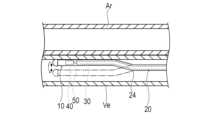
なお、本発明は、上述した実施形態のみに限定されるものではなく、本発明の技術的思想内において当業者により種々変更が可能である。例えば、図8に示すように、本実施形態に係る超音波カテーテル10は、隣接する2本の血管の一方に挿入されて、超音波カテーテル10が挿入されていない血管を観察するために使用されてもよい。例えば、超音波カテーテル10は、下肢や腹部の静脈Veに挿入されて、静脈Veと隣接する動脈Ar内を観察することができる。したがって、例えば動脈内にアテレクトミーデバイスを挿入して石灰化病変を削って取り除く手技を行う際に、動脈Ar内の石灰化病変およびアテレクトミーデバイスを観察できる。The present invention is not limited to the above-mentioned embodiment, and various modifications can be made by those skilled in the art within the technical concept of the present invention. For example, as shown in FIG. 8, the
また、図9(A)に示す第1の変形例のように、屈曲部(例えば、第1の屈曲部24)は、1つのみであってもよい。Also, as in the first modified example shown in Figure 9 (A), there may be only one bend (e.g., the first bend 24).
また、図9(B)に示す第2の変形例のように、超音波カテーテル10は、同じ側へ曲がる少なくとも2つの屈曲部(例えば、第1の屈曲部24および第2の屈曲部26)を有してもよい。これにより、外シース20は、第1の屈曲部24および第2の屈曲部26の各々の角度を小さくすることができる。このため、第1の屈曲部24および第2の屈曲部26の内部を回転しつつ軸心方向へ移動可能な駆動シャフト50の負担を低減して、回転不良や軸心方向への移動に対する不具合の発生を抑制できる。さらに、外シース20は、少なくとも2つの屈曲部によって、全体として大きく曲げることができるため、方向付けが容易となる。As shown in the second modified example in FIG. 9B, the
また、図9(C)に示す第3の変形例のように、超音波カテーテル10は、外シース20の先端から先端方向へ突出するワイヤ29が形成されてもよい。ワイヤ29の外径は、外シース20の外径よりも小さい。ワイヤ29の先端部は、湾曲している。ワイヤ29は、血管内で超音波カテーテル10を押し進める際に、進める血管を選択するためのガイドワイヤとしての機能を有する。これにより、超音波カテーテル10は、血管内で推し進めることが容易となる。As shown in the third modified example in FIG. 9(C), the
なお、本出願は、2020年3月13日に出願された日本特許出願2020-043662号に基づいており、それらの開示内容は、参照され、全体として、組み入れられている。This application is based on Japanese Patent Application No. 2020-043662 filed on March 13, 2020, the disclosures of which are hereby incorporated by reference in their entirety.
1 超音波カテーテルシステム
10 超音波カテーテル
20 外シース
23 基端側管状部
24 第1の屈曲部(屈曲部)
25 第1の管状部(管状部)
26 第2の屈曲部(屈曲部)
27 第2の管状部(管状部)
28 収容ルーメン
30 内シース
41 振動子
50 駆動シャフト
60 第1のハウジング
65 係合部
70 第2のハウジング
80 駆動装置
81 駆動部
812 基端側支持部
82 移動部
83 先端側支持部
L1 先端部長さ
L2 オフセット量
θ 曲げ角度
X 基準線 1
25 First tubular portion (tubular portion)
26 Second bent portion (bent portion)
27 Second tubular portion (tubular portion)
28: accommodation lumen 30: inner sheath 41: transducer 50: drive shaft 60: first housing 65: engagement portion 70: second housing 80: drive device 81: drive portion 812: base end side support portion 82: moving portion 83: distal end side support portion L1: distal end length L2: offset amount θ: bending angle X: reference line
Claims (10)
Translated fromJapanese前記収容ルーメンの内部を前記外シースの軸心に沿って移動可能な内シースと、
前記内シースおよび/または前記外シース内で回転可能な駆動シャフトと、
前記収容ルーメン内の前記内シースよりも先端側に配置され、前記駆動シャフトの先端に固定された振動子と、を有する超音波カテーテルであって、
前記外シースは、
前記収容ルーメンの最先端よりも基端側で所定の角度で予め曲がって形状付けられた屈曲部と、
前記屈曲部よりも先端側であって前記収容ルーメンの最先端よりも基端側に、前記屈曲部の軸心の曲率半径よりも大きい曲率半径の軸心を備えた管状部と、を有し、
前記外シースは、前記内シースに対して回転可能であることを特徴とする超音波カテーテル。 an outer sheath having a receiving lumen formed therein and communicating from a proximal end to a distal end;
an inner sheath movable along an axis of the outer sheath within the accommodation lumen;
a drive shaft rotatable within the inner sheath and/or the outer sheath;
a transducer disposed distal to the inner sheath in the housing lumen and fixed to a distal end of the drive shaft,
The outer sheath is
A bent portion that is bent in advance at a predetermined angle on the proximal side of the distal end of the accommodation lumen;
a tubular portion having an axis having a radius of curvature larger than the radius of curvature of the axis of the bent portion, the axis being located distal to the bent portion and proximal to the tip of the storage lumen;
An ultrasound catheter, wherein the outer sheath is rotatable relative to the inner sheath.
前記基端側管状部の少なくとも先端部の軸心が位置する直線的な基準線に沿って、最も基端側の前記屈曲部から前記外シースの最先端までの長さである先端部長さは、20~150mmであることを特徴とする請求項1~7のいずれか1項に記載の超音波カテーテル。 the outer sheath has a proximal tubular portion proximal to the most proximal bent portion,
The ultrasound catheter according to any one of claims 1 to 7, characterized in that a tip length, which is the length from the most proximal bent portion to the tip end of the outer sheath along a linear reference line on which the axis of at least the tip portion of the base-side tubular portion is located, is 20 to 150 mm.
前記外シースの最も基端側の屈曲部よりも先端側の部位のうちの、前記基端側管状部の少なくとも先端部の軸心が位置する直線的な基準線から当該基準線と垂直な方向へ最も離れている部位の軸心までの長さであるオフセット量は、5~30mmであることを特徴とする請求項1~8のいずれか1項に記載の超音波カテーテル。 the outer sheath has a proximal tubular portion proximal to the most proximal bent portion,
9. The ultrasound catheter according to claim 1, wherein an offset amount, which is a length from a linear reference line on which the axis of at least the tip of the base-end tubular portion is located to the axis of the portion of the outer sheath that is farthest from the linear reference line in a direction perpendicular to the reference line, of the portion of the outer sheath that is distal to the most proximal bend, is 5 to 30 mm.
前記超音波カテーテルは、
基端から先端へ連通する収容ルーメンが形成された外シースと、
前記収容ルーメンの内部を前記外シースの軸心に沿って移動可能な内シースと、
前記内シースおよび/または前記外シース内で回転可能な駆動シャフトと、
前記収容ルーメン内の前記内シースよりも先端側に配置され、前記駆動シャフトの先端に固定された振動子と、
前記外シースの基端部が固定されるとともに前記駆動シャフトおよび前記内シースが貫通する第1のハウジングと、
前記第1のハウジングの基端側に配置されて、前記内シースの基端部が固定されるとともに前記駆動シャフトを回転可能に保持する第2のハウジングと、を有し、
前記外シースは、前記収容ルーメンの最先端よりも基端側で所定の角度で予め曲がって形状付けられた屈曲部と、前記屈曲部よりも先端側であって前記収容ルーメンの最先端よりも基端側に、前記屈曲部の軸心の曲率半径よりも大きい曲率半径の軸心を備えた管状部と、を有し、前記外シースは、前記内シースに対して回転可能であり、
前記駆動装置は、前記第2のハウジングを支持可能な基端側支持部と、
前記基端側支持部を軸心方向へ移動させることが可能な移動部と、
前記駆動シャフトに回転力を伝えることが可能な駆動部と、
前記第1のハウジングを回転可能に支持できる先端側支持部と、を有することを特徴とする超音波カテーテルシステム。 An ultrasound catheter system having an ultrasound catheter and a drive device for driving the ultrasound catheter,
The ultrasound catheter comprises:
an outer sheath having a receiving lumen formed therein and communicating from a proximal end to a distal end;
an inner sheath movable along an axis of the outer sheath within the accommodation lumen;
a drive shaft rotatable within the inner sheath and/or the outer sheath;
a transducer disposed distal to the inner sheath in the accommodation lumen and fixed to a distal end of the drive shaft;
a first housing to which a proximal end of the outer sheath is fixed and through which the drive shaft and the inner sheath extend;
a second housing that is disposed on a proximal end side of the first housing, to which a proximal end of the inner sheath is fixed and that rotatably holds the drive shaft,
the outer sheath has a bent portion that is bent at a predetermined angle on the base end side of the most distal end of the accommodation lumen, and a tubular portion that is on the distal end side of the bent portion and on the base end side of the most distal end of the accommodation lumen and has an axis having a radius of curvature larger than the radius of curvature of the axis of the bent portion, the outer sheath being rotatable with respect to the inner sheath,
The drive device includes a base end support portion capable of supporting the second housing;
A moving unit capable of moving the base end support unit in an axial direction;
A drive unit capable of transmitting a rotational force to the drive shaft;
and a tip side support portion capable of rotatably supporting the first housing.
Applications Claiming Priority (3)
| Application Number | Priority Date | Filing Date | Title |
|---|---|---|---|
| JP2020043662 | 2020-03-13 | ||
| JP2020043662 | 2020-03-13 | ||
| PCT/JP2021/008616WO2021182317A1 (en) | 2020-03-13 | 2021-03-05 | Ultrasonic catheter and ultrasonic catheter system |
Publications (2)
| Publication Number | Publication Date |
|---|---|
| JPWO2021182317A1 JPWO2021182317A1 (en) | 2021-09-16 |
| JP7490749B2true JP7490749B2 (en) | 2024-05-27 |
Family
ID=77671686
Family Applications (1)
| Application Number | Title | Priority Date | Filing Date |
|---|---|---|---|
| JP2022507134AActiveJP7490749B2 (en) | 2020-03-13 | 2021-03-05 | Ultrasound catheter and ultrasound catheter system |
Country Status (5)
| Country | Link |
|---|---|
| US (1) | US20230000464A1 (en) |
| JP (1) | JP7490749B2 (en) |
| CN (1) | CN115243622A (en) |
| AU (1) | AU2021235371A1 (en) |
| WO (1) | WO2021182317A1 (en) |
Families Citing this family (1)
| Publication number | Priority date | Publication date | Assignee | Title |
|---|---|---|---|---|
| WO2025100516A1 (en)* | 2023-11-10 | 2025-05-15 | テルモ株式会社 | Catheter for image acquisition |
Citations (3)
| Publication number | Priority date | Publication date | Assignee | Title |
|---|---|---|---|---|
| US20170049511A1 (en) | 2015-08-21 | 2017-02-23 | Baylis Medical Company Inc. | Transvascular Electrosurgical Devices and Systems and Methods of using the same |
| JP2017525519A (en) | 2014-09-04 | 2017-09-07 | シルク・ロード・メディカル・インコーポレイテッドSilk Road Medical, Inc. | Methods and devices for transcarotid artery access |
| WO2019188658A1 (en) | 2018-03-29 | 2019-10-03 | テルモ株式会社 | Imaging device |
Family Cites Families (8)
| Publication number | Priority date | Publication date | Assignee | Title |
|---|---|---|---|---|
| JP3526478B2 (en)* | 1994-10-17 | 2004-05-17 | オリンパス株式会社 | Ultrasonic probe |
| JPH0928710A (en)* | 1995-07-18 | 1997-02-04 | Olympus Optical Co Ltd | Ultrasonic prove with bending mechanism |
| US6241744B1 (en)* | 1998-08-14 | 2001-06-05 | Fox Hollow Technologies, Inc. | Apparatus for deploying a guidewire across a complex lesion |
| JP4458571B2 (en)* | 1999-03-25 | 2010-04-28 | 弘樹 福島 | Cardiac catheter |
| JP2004105289A (en)* | 2002-09-13 | 2004-04-08 | Olympus Corp | Ultrasonic endoscope |
| JP2004298349A (en)* | 2003-03-31 | 2004-10-28 | Fuji Photo Optical Co Ltd | Ultrasonic probe |
| EP2714173B1 (en)* | 2011-05-27 | 2020-05-27 | Conavi Medical Inc. | Medical probe with fluid rotary joint |
| EP3307172A4 (en)* | 2015-06-15 | 2019-05-22 | Sunnybrook Research Institute | INTRAVASCULAR IMAGING CATHETERS AND METHODS OF USING SAME |
- 2021
- 2021-03-05JPJP2022507134Apatent/JP7490749B2/enactiveActive
- 2021-03-05AUAU2021235371Apatent/AU2021235371A1/enactivePending
- 2021-03-05WOPCT/JP2021/008616patent/WO2021182317A1/ennot_activeCeased
- 2021-03-05CNCN202180020064.6Apatent/CN115243622A/enactivePending
- 2022
- 2022-09-13USUS17/943,513patent/US20230000464A1/enactivePending
Patent Citations (3)
| Publication number | Priority date | Publication date | Assignee | Title |
|---|---|---|---|---|
| JP2017525519A (en) | 2014-09-04 | 2017-09-07 | シルク・ロード・メディカル・インコーポレイテッドSilk Road Medical, Inc. | Methods and devices for transcarotid artery access |
| US20170049511A1 (en) | 2015-08-21 | 2017-02-23 | Baylis Medical Company Inc. | Transvascular Electrosurgical Devices and Systems and Methods of using the same |
| WO2019188658A1 (en) | 2018-03-29 | 2019-10-03 | テルモ株式会社 | Imaging device |
Also Published As
| Publication number | Publication date |
|---|---|
| JPWO2021182317A1 (en) | 2021-09-16 |
| AU2021235371A1 (en) | 2022-10-20 |
| CN115243622A (en) | 2022-10-25 |
| WO2021182317A1 (en) | 2021-09-16 |
| US20230000464A1 (en) | 2023-01-05 |
Similar Documents
| Publication | Publication Date | Title |
|---|---|---|
| JP7254773B2 (en) | Imaging device | |
| US8147413B2 (en) | Image guided catheter having deployable balloons and pericardial access procedure | |
| EP2077760B1 (en) | Image guided catheters | |
| US20090287087A1 (en) | Devices for creating passages and sensing for blood vessels | |
| US12053237B2 (en) | Catheter and recanalization catheter system | |
| CN107427285B (en) | Device for intracardiac and endovascular surgery with intraluminal ultrasound probe | |
| JP2013516291A (en) | Improved catheter | |
| JP2004097286A (en) | Catheter | |
| US11529165B2 (en) | Catheter | |
| JP2021145860A (en) | Medical apparatus | |
| CN110809432A (en) | catheter for imaging diagnosis | |
| CN115363709A (en) | Bending-adjustable intravascular ultrasound-guided puncture method | |
| JP7490749B2 (en) | Ultrasound catheter and ultrasound catheter system | |
| JP2025506827A (en) | Medical Catheters | |
| JP2015146878A (en) | catheter | |
| JP6826847B2 (en) | Medical device | |
| JP6884538B2 (en) | Connection ports and medical devices | |
| WO2022071157A1 (en) | Driving shaft and catheter for image diagnosis | |
| US20230190231A1 (en) | Ultrasound catheter and ultrasound catheter system | |
| JP6779799B2 (en) | Medical device | |
| JP7591562B2 (en) | Healthcare System | |
| JP2024172739A (en) | Catheters and medical devices | |
| JPH10286308A (en) | Medical tube | |
| JP2018102608A (en) | Medical device and treatment method | |
| JP2018043038A (en) | Catheter and medical instrument |
Legal Events
| Date | Code | Title | Description |
|---|---|---|---|
| A621 | Written request for application examination | Free format text:JAPANESE INTERMEDIATE CODE: A621 Effective date:20231013 | |
| TRDD | Decision of grant or rejection written | ||
| A01 | Written decision to grant a patent or to grant a registration (utility model) | Free format text:JAPANESE INTERMEDIATE CODE: A01 Effective date:20240423 | |
| A61 | First payment of annual fees (during grant procedure) | Free format text:JAPANESE INTERMEDIATE CODE: A61 Effective date:20240515 | |
| R150 | Certificate of patent or registration of utility model | Ref document number:7490749 Country of ref document:JP Free format text:JAPANESE INTERMEDIATE CODE: R150 |