JP7489512B2 - Disaster Prevention System - Google Patents
Disaster Prevention SystemDownload PDFInfo
- Publication number
- JP7489512B2 JP7489512B2JP2023034225AJP2023034225AJP7489512B2JP 7489512 B2JP7489512 B2JP 7489512B2JP 2023034225 AJP2023034225 AJP 2023034225AJP 2023034225 AJP2023034225 AJP 2023034225AJP 7489512 B2JP7489512 B2JP 7489512B2
- Authority
- JP
- Japan
- Prior art keywords
- test
- fire
- address
- signal line
- disaster prevention
- Prior art date
- Legal status (The legal status is an assumption and is not a legal conclusion. Google has not performed a legal analysis and makes no representation as to the accuracy of the status listed.)
- Active
Links
Images


Classifications
- Y—GENERAL TAGGING OF NEW TECHNOLOGICAL DEVELOPMENTS; GENERAL TAGGING OF CROSS-SECTIONAL TECHNOLOGIES SPANNING OVER SEVERAL SECTIONS OF THE IPC; TECHNICAL SUBJECTS COVERED BY FORMER USPC CROSS-REFERENCE ART COLLECTIONS [XRACs] AND DIGESTS
- Y02—TECHNOLOGIES OR APPLICATIONS FOR MITIGATION OR ADAPTATION AGAINST CLIMATE CHANGE
- Y02A—TECHNOLOGIES FOR ADAPTATION TO CLIMATE CHANGE
- Y02A50/00—TECHNOLOGIES FOR ADAPTATION TO CLIMATE CHANGE in human health protection, e.g. against extreme weather
Landscapes
- Fire-Detection Mechanisms (AREA)
- Fire Alarms (AREA)
Description
Translated fromJapanese本発明は、火災検知器を防災監視盤に接続して火災を監視する防災システムに関する。The present invention relates to a disaster prevention system that monitors fires by connecting a fire detector to a disaster prevention monitoring panel.
従来、自動車専用道路等のトンネルには、トンネル内で発生する火災事故から人身及び車両を守るため、非常用施設が設置されている。Traditionally, emergency facilities have been installed in tunnels on expressways and other roads to protect people and vehicles from fires that may occur inside the tunnel.
このような非常用施設としては、火災の監視と通報のため火災検知器、手動通報装置、非常電話が設けられ、また火災の消火や延焼防止のために消火栓装置が設けられ、更にトンネル躯体を火災から防護するために水噴霧ヘッドから消火用水を散水してトンネル内の温度を下げる水噴霧設備などが設置され、これらの非常用施設の端末機器を監視制御する防災受信盤を設けることで、トンネル防災システムを構築している。Such emergency facilities include fire detectors, manual reporting devices, and emergency telephones for monitoring and reporting fires, as well as fire hydrants for extinguishing fires and preventing the spread of fires, and water spray equipment for lowering the temperature inside the tunnel by spraying fire-extinguishing water from water spray heads to protect the tunnel structure from fire. A tunnel disaster prevention system is constructed by installing a disaster prevention receiving panel that monitors and controls the terminal equipment of these emergency facilities.
防災受信盤と端末機器で構成するトンネル防災システムは、R型伝送方式とP型直送方式に大別される。R型伝送方式は、信号回線にアドレスを設定した火災検知器を接続し、伝送制御により火災検知器単位に検知を行う個別管理を可能とする。Tunnel disaster prevention systems, consisting of a disaster prevention receiving panel and terminal equipment, are broadly divided into R-type transmission methods and P-type direct transmission methods. The R-type transmission method connects fire detectors with addresses set to the signal line, enabling individual management of detection by fire detector unit through transmission control.
P型直送方式は、火災検知器を所定の自動通報区画単位に分け、防災受信盤から区画単位に引き出した信号回線に同一区画に属する複数の火災検知器を接続して監視している。P型直送方式の防災受信盤による火災判断は、火災検知器が火災を検知すると所定の時間間隔で火災パルス信号を出力することから、1パルス目を火災予告信号として処理する。続いて防災受信盤は、1パルス目の受信から所定時間を経過した場合に火災受信回路を一旦復旧させ、復旧から所定時間内に再度火災検知器から火災パルス信号を受信すると、火災と判断して火災警報等の対処処理を行い、一方、復旧から所定時間内に再度火災パルス信号を受信しない場合は、非火災として処理している。In the P-type direct transmission method, fire detectors are divided into predetermined automatic reporting compartment units, and multiple fire detectors belonging to the same compartment are connected to signal lines drawn from the disaster prevention receiving panel for each compartment for monitoring. When a fire detector detects a fire, it outputs a fire pulse signal at a specified time interval, and the first pulse is processed as a fire warning signal. Next, the disaster prevention receiving panel restores the fire receiving circuit once a specified time has passed since receiving the first pulse, and if it receives another fire pulse signal from the fire detector within the specified time after restoration, it determines that there is a fire and takes appropriate action such as a fire alarm. On the other hand, if it does not receive another fire pulse signal within the specified time after restoration, it processes it as a non-fire.
しかしながら、このような従来のP型直送方式のトンネル防災システムは、火災検知器を自動通報区画単位で監視するようにしていたため、自動通報区画数の多いトンネルに設置する防災受信盤には、区画数に応じた受信回路等のハードウェア構成が必要となり、防災受信盤の筐体サイズが大きくなり、コストも高くなる問題がある。However, this type of conventional P-type direct delivery tunnel disaster prevention system monitors fire detectors on an automatic reporting section basis, so a disaster prevention receiving panel installed in a tunnel with a large number of automatic reporting sections requires a hardware configuration of receiving circuits and other components according to the number of sections, which results in a problem of the disaster prevention receiving panel's housing becoming larger and more expensive.
例えば、2400メートルのトンネルの場合、火災検知器の監視領域を両側25メートルの範囲とすると、火災検知器は96台必要であり、自動通報区画は2台ずつの火災検知器を含むように設定することから48区画となり、これに対応して防災受信盤の受信回路は48入力分必要となり、防災受信盤の筐体サイズが大きくなり、コストも高くなる。For example, in the case of a 2,400-meter tunnel, if the fire detector monitoring area is set to a range of 25 meters on both sides, 96 fire detectors will be required, and since the automatic reporting sections are set to include two fire detectors each, there will be 48 sections. Correspondingly, the disaster prevention receiving panel will need a receiving circuit with 48 inputs, which will increase the size of the disaster prevention receiving panel housing and the cost.
また、防災受信盤と火災検知器との間の信号回線も自動通報区画数に対応して配線しており、防災受信盤と火災検知器の間に設置する配線量が区画数に応じて増加し、設備工事が大変で設備コストが高価になる問題もある。In addition, the signal lines between the disaster prevention receiving panel and the fire detectors are wired according to the number of automatic reporting sections, and the amount of wiring to be installed between the disaster prevention receiving panel and the fire detectors increases according to the number of sections, which creates the problem of difficult installation work and high installation costs.
本発明は、自動通報区画数が多くなっても防災受信盤の筐体サイズや配線量を増加することなくコストの低減を可能とする防災システムを提供することを目的とする。The objective of the present invention is to provide a disaster prevention system that allows costs to be reduced without increasing the size of the disaster prevention receiving panel case or the amount of wiring, even if the number of automatic reporting sections increases.
(防災システム)
本発明は、複数の子機を試験開始信号線及び試験中信号線を含む信号回線により順次接続し、信号回線の一端側を親機に接続して異常を監視する防災システムであって、
子機は、試験開始信号線の親機側である1次側から所定のアドレスを含む試験開始信号を受信した場合に、当該アドレスを自機のアドレスとして設定した試験中信号を試験中信号線により親機へ送信すると共に自機に関する所定の試験を実施し、試験の終了後に、試験中信号の送信を停止すると共に自機のアドレスを変更したアドレスを含む試験開始信号を試験開始信号線の2次側に送信することを特徴とする。 (Disaster prevention system)
The present invention relates to a disaster prevention system in which a plurality of slave units are sequentially connected by a signal line including a test start signal line and a test underway signal line, and one end of the signal line is connected to a master unit to monitor for abnormalities,
When the slave unit receives a test start signal including a specified address from the primary side, which is the parent unit side of the test start signal line, it transmits a test in progress signal with the address set as its own unit's address to the parent unit via the test in progress signal line and performs a specified test on its own unit, and after the test is completed, it stops transmitting the test in progress signal and transmits a test start signal including the changed address of its own unit to the secondary side of the test start signal line.
(基本的な効果)
本発明は、複数の子機を試験開始信号線及び試験中信号線を含む信号回線により順次接続し、信号回線の一端側を親機に接続して異常を監視する防災システムであって、子機は、試験開始信号線の親機側である1次側から所定のアドレスを含む試験開始信号を受信した場合に、当該アドレスを自機のアドレスとして設定した試験中信号を試験中信号線により親機へ送信すると共に自機に関する所定の試験を実施し、試験の終了後に、試験中信号の送信を停止すると共に自機のアドレスを変更したアドレスを含む試験開始信号を試験開始信号線の2次側に送信するようにしたため、信号線に接続された子機に対し、設定するアドレスを付した試験開始信号を送信して試験と合わせてアドレスを設定し、各子機にアドレスを設定するためだけに通信制御を行う必要がないことから、アドレス設定に伴う親機側の制御負担を低減して簡単且つ確実に子機にアドレスを自動設定することを可能とする。 (Basic Effects)
The present invention is a disaster prevention system in which a plurality of slave units are connected in sequence by signal lines including a test start signal line and a test in progress signal line, and one end of the signal line is connected to a parent unit to monitor for abnormalities. When a slave unit receives a test start signal including a predetermined address from the primary side, which is the parent unit side of the test start signal line, it transmits a test in progress signal with the address set as its own address to the parent unit via the test in progress signal line and performs a predetermined test related to itself. After the test is completed, it stops transmitting the test in progress signal and transmits a test start signal including a changed address of its own unit to the secondary side of the test start signal line. Therefore, a test start signal with the address to be set is transmitted to the slave units connected to the signal line to set the address in conjunction with the test, and there is no need to perform communication control just to set an address in each slave unit. This reduces the control burden on the parent unit associated with address setting, making it possible to automatically set addresses in the slave units simply and reliably.
また、運用中に異常を検知した場合に、試験により設定したアドレスを付した異常検知信号として送信することから、親機にアドレスと区画との対応関係を事前登録しておくことで、受信した異常検知信号のアドレスから異常を検知した自動通報区画を特定して報知でき、P型直送方式であっても従来のように異常を検知した子機を現場確認する手間を省くことができる。In addition, if an abnormality is detected during operation, it will be sent as an abnormality detection signal with the address set during testing. By pre-registering the correspondence between addresses and sections in the parent unit, the automatic reporting section where the abnormality was detected can be identified and notified from the address of the received abnormality detection signal. This eliminates the need to go to the site to check the child unit that detected the abnormality, as was done in the past, even with the P-type direct delivery method.
[トンネル防災システムの概要]
図1はトンネル防災システムの機能構成の概略を示したブロック図である。図1に示すように、トンネル内の異常を監視するため、監視センター等に防災受信盤10を設置している。 [Outline of tunnel disaster prevention system]
Fig. 1 is a block diagram showing an outline of the functional configuration of a tunnel disaster prevention system. As shown in Fig. 1, a disaster
自動車専用道路のトンネルは、上り線トンネルと下り線トンネルが構築され、トンネルの内部には、トンネル長手方向の壁面に沿って例えば25メートル間隔で火災検知器14を設置している。火災検知器14は左右25メートルとなる両側に監視エリアを設定し、火災による炎を検出して火災検知信号を防災受信盤10に送信する。トンネル内に25メートル間隔で設置した火災検知器14は、隣接する2台の火災検知器14により自動通報区画を形成している。A tunnel for an expressway is constructed with an up-bound tunnel and an down-bound tunnel, and inside the tunnel,
本実施形態の防災受信盤10にあっては、トンネル内に設置した火災検知器14の区画をD1~Dmとすると、例えば4区画に含まれる8台の火災検知器14を1グループとして、グループG1~Gnに分割しており、分割したグループG1~Gn毎に防災受信盤10から信号回線12を引き出し、各グループG1~Gnに属する8台の火災検知器14を接続している。In the disaster
このため防災受信盤10に設けた受信回路部18は、グループG1~Gnのグループ数に対応した台数を設けるだけでよく、従来の区画単位に受信回路部を設けていた場合に比べ、その台数を低減してハードウェアを簡単にでき、これにより防災受信盤10の筐体サイズを小型化し、信号回線12の配線量も低減し、設備コストを下げることを可能とする。Therefore, the number of receiving
例えば2400メートルのトンネルの場合、25メートル間隔で火災検知器14を96台設置しており、自動通報区画の区画数は2台の火災検知器単位であることから48区画となる。この場合、従来の区画単位に受信回路部18を設けた場合は48台必要であるが、本実施形態にあっては、例えば火災検知器14の8台をグループ化して信号回線12に接続していることから、受信回路部18は12台に低減することができる。For example, in the case of a 2,400-meter tunnel, 96
なお、グループ分割により同じ信号回線12に接続する火災検知器14の台数は図示の8台に限定されず、後の説明で明らかにする火災検知器14に検知器試験を通じて自動設定される最大アドレスの範囲で、8台以上をグループ化し、更に、受信回路部18の台数を低減することが可能である。The number of
防災受信盤10は制御部16を備え、制御部16は例えばプログラムの実行により実現される機能であり、ハードウェアとしてはCPU、メモリ、各種の入出力ポート等を備えたコンピュータ回路等を使用する。The disaster
制御部16に対しては、8台の火災検知器14を含むグループG1~Gn毎に引き出した信号回線12に対応して受信回路部18を設け、また、制御部16に対しスピーカ、ブザー、警報表示灯等を備えた警報部20、液晶ディスプレイ等を備えた表示部22、各種スイッチを備えた操作部24、IG子局設備を接続するモデム26を設け、更に、換気設備、警報表示板設備、ラジオ再放送設備、テレビ監視設備、照明設備及び消火ポンプ設備をP型信号回線により個別に接続したP型伝送部28を設けている。なお、モデム26で接続するIG子局設備は、防災受信盤10及びその他の設備と遠隔管理設備とを結ぶ通信設備である。For the
防災受信盤10の制御部16は、システム設置後に信号回線12毎に検知器試験を行うことにより、信号回線12単位に接続している8台の火災検知器14に固有のアドレスを自動的に設定する制御を行う。After the system is installed, the
また、防災受信盤10の制御部16は、検知器試験によるアドレス設定を終了した後の監視中に、火災検知器14から検知器試験により設定したアドレスを含む火災検知信号を受信した場合に、受信した火災検知信号に含まれるアドレスに基づき火災を検知した区画を判別して報知する制御を行う。In addition, when the
防災受信盤10の制御部16による検知器試験は、検知器試験操作を検出した場合に、所定の開始アドレス、例えばアドレスA=1を含む試験開始信号を信号回線12に送信する制御を伴う所定の検知器試験制御を行う。この防災受信盤10の検知器試験制御に対し信号回線12に接続した各火災検知器14は、防災受信盤10側となる1次側から試験開始信号を受信した場合に所定の試験動作を開始すると共に受信した試験開始信号に含まれるアドレスAを取り出して記憶し、試験を終了した場合に受信したアドレスAを1つ増加してアドレスA+1を含む試験開始信号を2次側に接続している次の火災検知器14に送信する制御を行い、アドレスAを1つ増加しながら8台の火災検知器14が自律的に試験開始信号を順番に送りながら固有のアドレスを自動的に設定する。When the
[火災検知器の構成]
図2は火災検知器に対する信号回線による信号線接続を示した説明図、図3は火災検知器の機能構成を示したブロック図である。 [Fire detector configuration]
FIG. 2 is an explanatory diagram showing signal line connections to a fire detector via signal circuits, and FIG. 3 is a block diagram showing the functional configuration of the fire detector.
(火災検知器と信号回線の接続)
図2に示すように、防災受信盤10から引き出された信号回線12には、電源線34、コモン線36、火災信号線38、試験中信号線40、試験電源線42,44及び試験開始信号線46aが含まれている。 (Connection of fire detector and signal line)
As shown in FIG. 2, the
図2は、防災受信盤12側に近い先頭の火災検知器14-1と次の火災検知器14-2を取出して信号回線12との接続を示しており、火災検知器14-1,14-2は、電源線34、コモン線36、火災信号線38、試験中信号線40、試験電源線42,44に対して並列に接続しているが、防災受信盤10からの試験開始信号線46aは火災検知器14-1に入力接続しており、また試験開始信号線46bを1次側の火災検知器14-1に出力接続すると共に2次側の火災検知器14-2に入力接続している。即ち、火災検知器14-1,14-2は試験開始信号線46a,46bにより防災受信盤10に対し直列に接続している。Figure 2 shows the connection of the first fire detector 14-1 closest to the disaster
火災検知器14-1,14-2は横に並べて左眼受光部30aと右眼受光部30bを備え、左右25メートルの範囲を監視領域に設定し、火災による炎を検知して火災検知信号を防災受信盤10に送信する。なお、以下の説明で火災検知器14-1,14-2を区別する必要がない場合は、火災検知器14とする。The fire detectors 14-1 and 14-2 are arranged side by side and equipped with a left eye
(火災検知器の構成)
図3に示すように、火災検知器14-1は制御部50を備え、制御部50は例えばプログラムの実行により実現される機能であり、ハードウェアとしてはCPU、メモリ、各種の入出力ポート等を備えたコンピュータ回路等を使用する。 (Fire detector configuration)
As shown in FIG. 3, the fire detector 14-1 is equipped with a
制御部50に対しては、左眼火災検知部48a、右眼火災検知部48b、試験伝送部52及び火災伝送部54を設けている。試験伝送部52に対しては試験中信号線40、試験電源線42,44を並列的に接続し、1次側の試験開始信号線46aを入力接続し、2次側の試験開始信号線46bを出力接続している。The
左眼火災検知部48aと右眼火災検知部48bは、例えば2波長式の炎検知により火災を監視している。即ち、左眼火災検知部48aと右眼火災検知部48bは、炎に特有なCO2の共鳴放射帯である4.4~4.5μmの放射エネルギーを狭帯域の光学波長バンドパスフィルタにより選択透過(通過)させて、受光センサにより該放射線エネルギーを検出して光電変換したうえで、増幅等所定の加工を施してエネルギー量に対応する受光信号に処理し、受光信号レベルの相対比をとり、所定の閾値と比較することにより炎の有無を判定する。The left eye
火災検知器14-1の制御部50は、左眼火災検知部48a又は右眼火災検知部48bによる炎有りの判定により火災を検知した場合には、火災伝送部54に指示して所定の時間間隔で所定パルス幅の火災パルスに自己アドレスを示すアドレスパルスを組み合わせた火災検知信号を周期的に火災信号線38に送信させる制御を行う。When the
また、火災検知器14-1の制御部50は、防災受信盤10の検知器試験に伴い試験電源線42,44に出力された転極電圧と試験開始信号線46aに出力されたアドレスA=1を含む試験開始信号を試験伝送部52を介して受信した場合、右眼火災検知部48bと左眼火災検知部48aに対し所定の試験動作を行って試験による火災検知信号を送信させる制御を行う。In addition, when the
また、火災検知器14の制御部50は、試験開始信号を受信した場合に、試験開始信号に含まれるアドレスA=1を自己アドレスとして取り出してメモリに記憶し、また、次の火災検知器14-2のアドレス設定のために、受信したアドレスAを1つ増加したアドレスA=A+1=2とし、検知器試験が終了した場合に、増加したアドレスA=2を試験開始信号に含めて2次側の試験開始信号線46bに出力する制御を行う。なお、受信したアドレスAの変更は、1つ増加したアドレスA=A+1とする以外に、2以上の複数の値だけ増加したアドレスとしても良いし、所定の係数を乗算して増加するようにしたアドレスとしても良い。When the
(試験開始信号)
図4は検知器試験で使用する試験開始パルスとアドレスパルスを組み合わせた試験開始信号を示した説明図である。 (Test start signal)
FIG. 4 is an explanatory diagram showing a test start signal which is a combination of a test start pulse and an address pulse used in a detector test.
図4(A)は試験開始信号60のフォーマットであり、例えばパルス幅8ミリ秒の試験開始パルス62に続いて22ミリ秒のアドレスパルス64を組合せ、アドレスパルス64は1ミリ秒の1ビットパルス66を組み合わせた22ビット長のアドレスを設定可能としている。Figure 4 (A) shows the format of the
図4(B)~図4(I)は図1に示したグループG1に設けた8台の火災検知器14にアドレスA=1~8をそれぞれ自動設定するための試験開始信号60-1~60-8を示している。試験開始信号60-1~60-8は先頭に試験開始パルス62を固定配置し、これに続いてアドレスA=1~8を2進表示した1000・・・0,0100・・・0,~000・・・0となるアドレスパルスを組み合わせている。Figures 4(B) to 4(I) show test start signals 60-1 to 60-8 for automatically setting addresses A = 1 to 8 to the eight
(検知器試験動作)
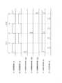
図5は火災検知器の試験における各信号線の信号波形を示したタイムチャートであり、図2に示した火災検知器14-2,14-2の検知器試験を例にとっている。 (Detector test operation)
FIG. 5 is a time chart showing the signal waveforms of the signal lines in a test of a fire detector, taking as an example a detector test of the fire detectors 14-2, 14-2 shown in FIG.
検知器試験を行う場合、防災受信盤10は図5(A)(B)に示すように、試験電源線42,44に対する試験電圧の極性を所定の時間間隔で交互に切替える転極制御を行い、試験電源線42をプラスとする転極で火災検知器14の右眼火災検知部48bの試験を可能とする。When performing a detector test, the disaster
時刻t1で火災検知器14-1が試験開始信号線46aを介して図4(B)に示した試験開始信号60-1を受信すると、試験開始パルス62により試験電源線44をプラスとする転極に同期して火災検知器14の右眼火災検知部48bの試験を行い、正常に試験が行われると図5(G)に示すように、試験による火災パルス信号を防災受信盤10に火災信号線38により送信する。When the fire detector 14-1 receives the test start signal 60-1 shown in FIG. 4(B) via the test
続いて、試験電源線42をプラスとする転極に同期して火災検知器14の左眼火災検知部48aの試験を行い、正常に試験が行われると図5(G)に示すように、試験による火災パルス信号を防災受信盤10に火災信号線38により送信する。また、検知器試験中は図5(F)に示すように、試験中信号線40に試験中信号を出力しており、防災受信盤10及び火災検知器14-2を含む他の火災検知器に検知器試験中にあることを認識させる。Then, in synchronization with the polarity inversion of the test power line 42 to positive, a test is performed on the left eye
火災検知器14-1は、受信した試験開始信号60-1からアドレスA=1を取出し、メモリに自己アドレスとして記憶し、次の火災検知器14-2に設定するアドレスとして1つ増加したアドレスA=2を生成する。The fire detector 14-1 extracts address A=1 from the received test start signal 60-1, stores it in memory as its own address, and generates address A=2, which is incremented by one, as the address to be set in the next fire detector 14-2.
続いて、火災検知器14-1は、検知器試験を終了すると試験電源線42がプラスとなる時刻t3のタイミングで2次側の試験開始信号線46bに図4(C)に示した試験開始パルス62にアドレスA=2のアドレスパルス64を組み合わせた試験開始信号60-2を送信する。Then, when the fire detector 14-1 finishes the detector test, it transmits a test start signal 60-2, which combines the test start pulse 62 shown in FIG. 4(C) with an
2番目に配置した火災検知器14-2は1次側に配置した火災検知器14-1が送信した試験開始信号60-2を試験開始信号線46bから受信して火災検知器14-1の場合と同様に検知器試験を行う。また、火災検知器14-2は、受信した試験開始信号60-2からアドレスA=2を取出し、メモリに自己アドレスとして記憶し、次の火災検知器14-3に設定するアドレスとして1つ増加したアドレスA=3を生成する。The second fire detector 14-2 receives the test start signal 60-2 sent by the fire detector 14-1 placed on the primary side from the test
続いて、火災検知器14-2は、検知器試験を終了すると試験電源線42がプラスとなる時刻t5のタイミングで2次側の試験開始信号線46cに図4(D)に示した試験開始パルス62にアドレスA=3のアドレスパルス64を組み合わせた試験開始信号60-3を送信する。Then, when the fire detector 14-2 finishes the detector test, it transmits a test start signal 60-3 to the secondary side test
以下、火災検知器14-2に続く残り6台の火災検知器についても同様な検知器試験を通じて固有のアドレスA=3~8を自動的に設定する。The remaining six fire detectors following fire detector 14-2 will also automatically be set to unique addresses A = 3 to 8 through similar detector tests.
(防災受信盤の管理情報)
図6は防災受信盤に登録した火災検知器のアドレスと区画の対応を示す管理情報を示した説明図である。 (Management information for disaster prevention receiving panel)
FIG. 6 is an explanatory diagram showing management information indicating the correspondence between the addresses of fire detectors registered in the disaster prevention receiving panel and partitions.
図1に示した防災受信盤10の制御部16に設けたメモリには、図6に示す信号回線単位に接続した8台の火災検知器14のアドレスと自動通報区画D1~Dmとの対応関係を示す管理情報を予め記憶して登録している。The memory provided in the
図6の管理情報は、信号回線12毎に系統L1~Lnを設定し、例えば系統L1に対応した8台の火災検知器のアドレス1~8に対応して区画D1~D4を火災検知器14の2台毎に設定している。The management information in Figure 6 sets lines L1 to Ln for each
このような管理情報を防災受信盤10に予め登録しておくことで、火災検知器14から火災検知信号を受信した場合、火災検知信号に含まれるアドレスにより管理情報を検索して対応する区画を取得し、火災を検知した自動通報区画を表示部22のディスプレイ上に表示し、トンネル内に出向いて現場確認を必要とすることなく、火災を検知した自動通報区画を知って適切且つ迅速な対処を可能とする。By registering such management information in advance in the disaster
(火災検知器の制御動作)
図7は火災検知器の制御動作を示したフローチャートである。図7に示すように、火災検知器14の制御部50は、防災受信盤10の検知器試験による転極制御に対応してステップS1で試験電源線42をプラスとする転極を検出するとステップS2に進み、ステップS2で1次側からの試験開始信号の受信を検出するとステップS3に進み、試験開始信号に含まれたアドレスAを抽出して自己アドレスとしてメモリに記憶し、続いて、次の火災検知器のアドレス設定のため受信したアドレスAに1を加算してA=A+1とする。 (Fire detector control operation)
Fig. 7 is a flow chart showing the control operation of the fire detector. As shown in Fig. 7, when the
続いてステップS5で試験中信号線40に試験中信号を送信して右眼火災検知部48b側の試験を行い、試験により炎検知を判別すると火災検知信号を防災受信盤10に送信する。Next, in step S5, a test in progress signal is sent to the test in progress signal line 40 to test the right eye fire detection unit 48b side, and if the test determines that a flame has been detected, a fire detection signal is sent to the disaster
続いてステップS6で試験電源線44をプラスとする転極を検出すると、ステップS7に進んで左眼火災検知部48a側の試験を行い、試験により炎検知を判別すると火災検知信号を防災受信盤10に送信する。Next, if a polarity reversal that makes the test power line 44 positive is detected in step S6, the process proceeds to step S7 where a test is performed on the left eye
続いてステップS8で試験電源線42側を再びプラスとする転極を検出すると、検知器試験の終了と判断してステップS9で試験中信号の出力を停止してステップS10に進み、ステップS4で変更したアドレスAを含む試験開始信号を生成して2次側の試験開始信号線に送信する。Next, when a polarity reversal is detected in step S8 that makes the test power line 42 positive again, it is determined that the detector test is finished, and in step S9 the output of the test in progress signal is stopped, and the process proceeds to step S10, where a test start signal including the address A changed in step S4 is generated and transmitted to the test start signal line on the secondary side.
このような検知器試験によるアドレスの自動設定が済むと、ステップS11に進んで火災検知の監視状態となり、ステップS11で火災検知を判別するとステップS12に進み、検知器試験で記憶した自己アドレスを含む火災検知信号を生成し、周期的に火災検知信号を送信する。Once the address has been automatically set by this detector test, the process proceeds to step S11 and the device enters a fire detection monitoring state. If a fire is detected in step S11, the process proceeds to step S12, where a fire detection signal is generated that includes the self address stored in the detector test, and the fire detection signal is transmitted periodically.
[本発明の変形例]
(端末子機にアドレスを自動設定するシステム)
上記の実施形態のトンネル防災システムに示した検知器試験を通じて信号回線に接続した複数の火災検知器にアドレスを自動設定する点は、一般的な適宜の親機から引き出された信号回線にアドレス未設定の端末子機を複数接続したシステムに適用できる。 [Modifications of the present invention]
(System that automatically sets addresses on terminal devices)
The automatic setting of addresses to multiple fire detectors connected to a signal line through the detector test shown in the tunnel disaster prevention system of the above embodiment can be applied to a system in which multiple terminal sub-units with unassigned addresses are connected to a signal line drawn from a general appropriate parent unit.
このようなシステムにあっては、親機に、所定のアドレスを含むアドレス設定信号を信号回線に送信する制御部を設け、信号回線に接続した各端末子機に、親機側となる1次側から受信したアドレス設定信号に含まれるアドレスを取り出して記憶すると、受信したアドレスを変更したアドレスを含むアドレス設定信号を2次側に送信する制御部を設けるようする。In such a system, the parent unit is provided with a control unit that transmits an address setting signal including a specified address to the signal line, and each terminal unit connected to the signal line is provided with a control unit that extracts and stores the address included in the address setting signal received from the primary side (parent unit) and transmits an address setting signal including an address obtained by modifying the received address to the secondary side.
このようなシステム構成を設けることにより、親機は、信号回線の先頭に接続している端末子機に対し先頭アドレスを含むアドレス設定信号を送信してアドレスを設定すると、それ以降は、アドレス設定を終了した端末子機が自己に設定したアドレスを例えば1つ増加したアドレスを含むアドレス設定信号を次の端末子機に送信してアドレス設定を次々と自律的に行い、親機から各端末子機に個別にアドレスを設定する通信制御を行う必要がないことから、アドレス設定に伴う親機側の制御負担を低減して簡単且つ確実に端末子機に固有のアドレスを自動設定することを可能とする。By configuring this system, the parent unit sets the address by sending an address setting signal including the top address to the terminal handset connected to the top of the signal line. Thereafter, the terminal handset that has completed address setting sends an address setting signal including an address that is, for example, an address that is one address larger than the address it has set itself to the next terminal handset, autonomously setting addresses one after another. This eliminates the need for communication control from the parent unit to set addresses individually for each terminal handset, reducing the control burden on the parent unit associated with address setting and making it possible to automatically set unique addresses to the terminal handset simply and reliably.
(検知器試験)
上記の実施形態に示した防災受信盤による火災検知器の試験は一例であり、防災受信盤からアドレスを含む試験開始信号を送信し、火災検知器は1次側から試験開始信号を受信して検知器試験を行うと共にアドレスを抽出して自己アドレスとして記憶し、試験終了で変更したアドレスを含む試験開始信号を2次側に送信する点を含むものであれば、試験電源の転極制御や試験中信号の出力等に制約されることなく、適宜の検知器試験の制御に適用可能である。 (Detector Test)
The testing of a fire detector using the disaster prevention receiving panel shown in the above embodiment is just one example, and as long as it includes the steps of transmitting a test start signal including an address from the disaster prevention receiving panel, and the fire detector receiving the test start signal from the primary side and performing a detector test while extracting the address and storing it as its own address, and transmitting a test start signal including the changed address to the secondary side upon completion of the test, it can be applied to the control of an appropriate detector test without being restricted by the polarity reversal control of the test power supply or the output of a test in progress signal, etc.
(その他)
また、本発明は、その目的と利点を損なわない適宜の変形を含み、更に上記の実施形態に示した数値による限定は受けない。 (others)
Furthermore, the present invention includes appropriate modifications that do not impair the objects and advantages of the present invention, and is not limited to the numerical values shown in the above embodiment.
10:防災受信盤
12:信号回線
14,14-1,14-2:火災検知器
16,50:制御部
18:受信回路部
30a:左眼受光部
30b:右眼受光部
34:電源線
36:コモン線
38:火災信号線
40:試験中信号線
42,44:試験電源線
46a,46b,46c:試験開始信号線
48a:左眼火災検知部
48b:右眼火災検知部
52:試験伝送部
54:火災伝送部
60:試験開始信号
62:試験開始パルス
64:アドレスパルス
66:1ビットパルス10: Disaster prevention receiving panel 12:
Claims (1)
Translated fromJapanese前記子機は、前記試験開始信号線の前記親機側である1次側から所定のアドレスを含む試験開始信号を受信した場合に、前記アドレスを自機のアドレスとして設定し、前記自機のアドレスを付した試験中信号を前記試験中信号線により前記親機へ送信すると共に自機に関する所定の試験を実施し、前記試験の終了後に、前記試験中信号の送信を停止すると共に前記自機のアドレスを変更したアドレスを含む試験開始信号を前記試験開始信号線の2次側に送信することを特徴とする防災システム。 A disaster prevention system in which a plurality of slave units are sequentially connected by a signal line including a test start signal line and a test underway signal line, and one end of the signal line is connected to a master unit to monitor for abnormalities,
A disaster prevention system characterized in that, when the slave unit receives a test start signal including a specified address from the primary side, which is the parent unit side, of the test start signal line, it sets the address as its own address, sends a test in progress signal with its own address attached to it to the parent unit via the test in progress signal line and performs a specified test on its own unit, and, after the test is completed, stops sending the test in progress signal and sends a test start signal including a changed address of the slave unit to the secondary side of the test start signal line.
Priority Applications (1)
| Application Number | Priority Date | Filing Date | Title |
|---|---|---|---|
| JP2023034225AJP7489512B2 (en) | 2020-06-22 | 2023-03-07 | Disaster Prevention System |
Applications Claiming Priority (3)
| Application Number | Priority Date | Filing Date | Title |
|---|---|---|---|
| JP2020106733AJP6949175B2 (en) | 2019-06-21 | 2020-06-22 | Tunnel disaster prevention system |
| JP2021152854AJP7241831B2 (en) | 2020-06-22 | 2021-09-21 | disaster prevention system |
| JP2023034225AJP7489512B2 (en) | 2020-06-22 | 2023-03-07 | Disaster Prevention System |
Related Parent Applications (1)
| Application Number | Title | Priority Date | Filing Date |
|---|---|---|---|
| JP2021152854ADivisionJP7241831B2 (en) | 2020-06-22 | 2021-09-21 | disaster prevention system |
Publications (2)
| Publication Number | Publication Date |
|---|---|
| JP2023065643A JP2023065643A (en) | 2023-05-12 |
| JP7489512B2true JP7489512B2 (en) | 2024-05-23 |
Family
ID=78890691
Family Applications (2)
| Application Number | Title | Priority Date | Filing Date |
|---|---|---|---|
| JP2021152854AActiveJP7241831B2 (en) | 2020-06-22 | 2021-09-21 | disaster prevention system |
| JP2023034225AActiveJP7489512B2 (en) | 2020-06-22 | 2023-03-07 | Disaster Prevention System |
Family Applications Before (1)
| Application Number | Title | Priority Date | Filing Date |
|---|---|---|---|
| JP2021152854AActiveJP7241831B2 (en) | 2020-06-22 | 2021-09-21 | disaster prevention system |
Country Status (1)
| Country | Link |
|---|---|
| JP (2) | JP7241831B2 (en) |
Families Citing this family (1)
| Publication number | Priority date | Publication date | Assignee | Title |
|---|---|---|---|---|
| KR20250139044A (en)* | 2024-03-14 | 2025-09-23 | 주식회사 로제에이아이코리아 | Fire alarm system and method of operation thereof |
Citations (5)
| Publication number | Priority date | Publication date | Assignee | Title |
|---|---|---|---|---|
| JP2006099394A (en) | 2004-09-29 | 2006-04-13 | Horiba Ltd | Fire detection system and method for controlling the same system |
| JP2006209800A (en) | 1999-03-15 | 2006-08-10 | Nittan Co Ltd | Test system, test method and sensor |
| JP2011187005A (en) | 2010-03-11 | 2011-09-22 | Nohmi Bosai Ltd | Fire detector |
| JP2012174313A (en) | 2011-02-23 | 2012-09-10 | Advantest Corp | Testing device |
| JP2013105370A (en) | 2011-11-15 | 2013-05-30 | Nohmi Bosai Ltd | Fire detector |
Family Cites Families (3)
| Publication number | Priority date | Publication date | Assignee | Title |
|---|---|---|---|---|
| JP3277406B2 (en)* | 1993-05-11 | 2002-04-22 | 能美防災株式会社 | Radiation fire detector |
| JP3229760B2 (en)* | 1994-12-22 | 2001-11-19 | ホーチキ株式会社 | Disaster prevention monitoring system |
| JP3368170B2 (en)* | 1997-04-23 | 2003-01-20 | 松下電工株式会社 | Outdoor indicator with remote test terminal |
- 2021
- 2021-09-21JPJP2021152854Apatent/JP7241831B2/enactiveActive
- 2023
- 2023-03-07JPJP2023034225Apatent/JP7489512B2/enactiveActive
Patent Citations (5)
| Publication number | Priority date | Publication date | Assignee | Title |
|---|---|---|---|---|
| JP2006209800A (en) | 1999-03-15 | 2006-08-10 | Nittan Co Ltd | Test system, test method and sensor |
| JP2006099394A (en) | 2004-09-29 | 2006-04-13 | Horiba Ltd | Fire detection system and method for controlling the same system |
| JP2011187005A (en) | 2010-03-11 | 2011-09-22 | Nohmi Bosai Ltd | Fire detector |
| JP2012174313A (en) | 2011-02-23 | 2012-09-10 | Advantest Corp | Testing device |
| JP2013105370A (en) | 2011-11-15 | 2013-05-30 | Nohmi Bosai Ltd | Fire detector |
Also Published As
| Publication number | Publication date |
|---|---|
| JP2023065643A (en) | 2023-05-12 |
| JP7241831B2 (en) | 2023-03-17 |
| JP2021192309A (en) | 2021-12-16 |
Similar Documents
| Publication | Publication Date | Title |
|---|---|---|
| JP7253583B2 (en) | disaster prevention system | |
| KR101311950B1 (en) | Fire detecing and alarm system | |
| JP6722805B2 (en) | Smoke detector | |
| JP7489512B2 (en) | Disaster Prevention System | |
| KR101424088B1 (en) | Nuclear power plant redundancy alarm system using field data collection devices and alarm logic sequence control device | |
| JP7527443B2 (en) | Fire alarm system | |
| JP3788711B2 (en) | Fire alarm system | |
| JP6949175B2 (en) | Tunnel disaster prevention system | |
| JP6546469B2 (en) | Tunnel disaster prevention system | |
| JP2018147373A (en) | Tunnel disaster prevention system | |
| KR101311951B1 (en) | Fire detecing and alarm system | |
| JP3563254B2 (en) | Fire alarm and detector | |
| KR101797730B1 (en) | Smart Alarm warning System | |
| JPS6019559B2 (en) | fire alarm system receiver | |
| JP7336252B2 (en) | Tunnel disaster prevention system | |
| JP7667769B2 (en) | Disaster Prevention System | |
| JP7299963B2 (en) | alarm system | |
| JPH0218759B2 (en) | ||
| JPH03282999A (en) | Radio type alarm system | |
| JPH01276398A (en) | Disaster prevention equipment | |
| JPS5830640B2 (en) | Kasaihouchisetsubi | |
| JPH03222096A (en) | Fire alarm system with operation testing function and analog sensor used therein | |
| JP3440717B2 (en) | Operation test method of remote tester and remote tester with automatic test function | |
| JP2023052809A (en) | disaster prevention system | |
| JP2021086367A (en) | Fire alarm facilities |
Legal Events
| Date | Code | Title | Description |
|---|---|---|---|
| A521 | Request for written amendment filed | Free format text:JAPANESE INTERMEDIATE CODE: A821 Effective date:20230307 | |
| A621 | Written request for application examination | Free format text:JAPANESE INTERMEDIATE CODE: A621 Effective date:20230403 | |
| TRDD | Decision of grant or rejection written | ||
| A01 | Written decision to grant a patent or to grant a registration (utility model) | Free format text:JAPANESE INTERMEDIATE CODE: A01 Effective date:20240424 | |
| A61 | First payment of annual fees (during grant procedure) | Free format text:JAPANESE INTERMEDIATE CODE: A61 Effective date:20240513 | |
| R150 | Certificate of patent or registration of utility model | Ref document number:7489512 Country of ref document:JP Free format text:JAPANESE INTERMEDIATE CODE: R150 |