JP7489367B2 - Active suspension device and vehicle equipped with active suspension device - Google Patents
Active suspension device and vehicle equipped with active suspension deviceDownload PDFInfo
- Publication number
- JP7489367B2 JP7489367B2JP2021182452AJP2021182452AJP7489367B2JP 7489367 B2JP7489367 B2JP 7489367B2JP 2021182452 AJP2021182452 AJP 2021182452AJP 2021182452 AJP2021182452 AJP 2021182452AJP 7489367 B2JP7489367 B2JP 7489367B2
- Authority
- JP
- Japan
- Prior art keywords
- control
- preview
- preview control
- wheel
- road surface
- Prior art date
- Legal status (The legal status is an assumption and is not a legal conclusion. Google has not performed a legal analysis and makes no representation as to the accuracy of the status listed.)
- Active
Links
Images


Classifications
- B—PERFORMING OPERATIONS; TRANSPORTING
- B60—VEHICLES IN GENERAL
- B60G—VEHICLE SUSPENSION ARRANGEMENTS
- B60G17/00—Resilient suspensions having means for adjusting the spring or vibration-damper characteristics, for regulating the distance between a supporting surface and a sprung part of vehicle or for locking suspension during use to meet varying vehicular or surface conditions, e.g. due to speed or load
- B60G17/015—Resilient suspensions having means for adjusting the spring or vibration-damper characteristics, for regulating the distance between a supporting surface and a sprung part of vehicle or for locking suspension during use to meet varying vehicular or surface conditions, e.g. due to speed or load the regulating means comprising electric or electronic elements
- B60G17/016—Resilient suspensions having means for adjusting the spring or vibration-damper characteristics, for regulating the distance between a supporting surface and a sprung part of vehicle or for locking suspension during use to meet varying vehicular or surface conditions, e.g. due to speed or load the regulating means comprising electric or electronic elements characterised by their responsiveness, when the vehicle is travelling, to specific motion, a specific condition, or driver input
- B60G17/0165—Resilient suspensions having means for adjusting the spring or vibration-damper characteristics, for regulating the distance between a supporting surface and a sprung part of vehicle or for locking suspension during use to meet varying vehicular or surface conditions, e.g. due to speed or load the regulating means comprising electric or electronic elements characterised by their responsiveness, when the vehicle is travelling, to specific motion, a specific condition, or driver input to an external condition, e.g. rough road surface, side wind
- B—PERFORMING OPERATIONS; TRANSPORTING
- B60—VEHICLES IN GENERAL
- B60G—VEHICLE SUSPENSION ARRANGEMENTS
- B60G17/00—Resilient suspensions having means for adjusting the spring or vibration-damper characteristics, for regulating the distance between a supporting surface and a sprung part of vehicle or for locking suspension during use to meet varying vehicular or surface conditions, e.g. due to speed or load
- B60G17/015—Resilient suspensions having means for adjusting the spring or vibration-damper characteristics, for regulating the distance between a supporting surface and a sprung part of vehicle or for locking suspension during use to meet varying vehicular or surface conditions, e.g. due to speed or load the regulating means comprising electric or electronic elements
- B60G17/019—Resilient suspensions having means for adjusting the spring or vibration-damper characteristics, for regulating the distance between a supporting surface and a sprung part of vehicle or for locking suspension during use to meet varying vehicular or surface conditions, e.g. due to speed or load the regulating means comprising electric or electronic elements characterised by the type of sensor or the arrangement thereof
- B—PERFORMING OPERATIONS; TRANSPORTING
- B60—VEHICLES IN GENERAL
- B60G—VEHICLE SUSPENSION ARRANGEMENTS
- B60G17/00—Resilient suspensions having means for adjusting the spring or vibration-damper characteristics, for regulating the distance between a supporting surface and a sprung part of vehicle or for locking suspension during use to meet varying vehicular or surface conditions, e.g. due to speed or load
- B60G17/06—Characteristics of dampers, e.g. mechanical dampers
- B—PERFORMING OPERATIONS; TRANSPORTING
- B60—VEHICLES IN GENERAL
- B60G—VEHICLE SUSPENSION ARRANGEMENTS
- B60G2202/00—Indexing codes relating to the type of spring, damper or actuator
- B60G2202/40—Type of actuator
- B60G2202/41—Fluid actuator
- B—PERFORMING OPERATIONS; TRANSPORTING
- B60—VEHICLES IN GENERAL
- B60G—VEHICLE SUSPENSION ARRANGEMENTS
- B60G2400/00—Indexing codes relating to detected, measured or calculated conditions or factors
- B60G2400/10—Acceleration; Deceleration
- B60G2400/102—Acceleration; Deceleration vertical
- B—PERFORMING OPERATIONS; TRANSPORTING
- B60—VEHICLES IN GENERAL
- B60G—VEHICLE SUSPENSION ARRANGEMENTS
- B60G2400/00—Indexing codes relating to detected, measured or calculated conditions or factors
- B60G2400/20—Speed
- B—PERFORMING OPERATIONS; TRANSPORTING
- B60—VEHICLES IN GENERAL
- B60G—VEHICLE SUSPENSION ARRANGEMENTS
- B60G2400/00—Indexing codes relating to detected, measured or calculated conditions or factors
- B60G2400/20—Speed
- B60G2400/204—Vehicle speed
- B—PERFORMING OPERATIONS; TRANSPORTING
- B60—VEHICLES IN GENERAL
- B60G—VEHICLE SUSPENSION ARRANGEMENTS
- B60G2400/00—Indexing codes relating to detected, measured or calculated conditions or factors
- B60G2400/25—Stroke; Height; Displacement
- B60G2400/252—Stroke; Height; Displacement vertical
- B—PERFORMING OPERATIONS; TRANSPORTING
- B60—VEHICLES IN GENERAL
- B60G—VEHICLE SUSPENSION ARRANGEMENTS
- B60G2400/00—Indexing codes relating to detected, measured or calculated conditions or factors
- B60G2400/80—Exterior conditions
- B60G2400/82—Ground surface
- B—PERFORMING OPERATIONS; TRANSPORTING
- B60—VEHICLES IN GENERAL
- B60G—VEHICLE SUSPENSION ARRANGEMENTS
- B60G2400/00—Indexing codes relating to detected, measured or calculated conditions or factors
- B60G2400/80—Exterior conditions
- B60G2400/82—Ground surface
- B60G2400/824—Travel path sensing; Track monitoring
- B—PERFORMING OPERATIONS; TRANSPORTING
- B60—VEHICLES IN GENERAL
- B60G—VEHICLE SUSPENSION ARRANGEMENTS
- B60G2401/00—Indexing codes relating to the type of sensors based on the principle of their operation
- B60G2401/14—Photo or light sensitive means, e.g. Infrared
- B60G2401/142—Visual Display Camera, e.g. LCD
- B—PERFORMING OPERATIONS; TRANSPORTING
- B60—VEHICLES IN GENERAL
- B60G—VEHICLE SUSPENSION ARRANGEMENTS
- B60G2401/00—Indexing codes relating to the type of sensors based on the principle of their operation
- B60G2401/16—GPS track data
- B—PERFORMING OPERATIONS; TRANSPORTING
- B60—VEHICLES IN GENERAL
- B60G—VEHICLE SUSPENSION ARRANGEMENTS
- B60G2401/00—Indexing codes relating to the type of sensors based on the principle of their operation
- B60G2401/21—Laser
- B—PERFORMING OPERATIONS; TRANSPORTING
- B60—VEHICLES IN GENERAL
- B60G—VEHICLE SUSPENSION ARRANGEMENTS
- B60G2401/00—Indexing codes relating to the type of sensors based on the principle of their operation
- B60G2401/28—Gyroscopes
- B—PERFORMING OPERATIONS; TRANSPORTING
- B60—VEHICLES IN GENERAL
- B60G—VEHICLE SUSPENSION ARRANGEMENTS
- B60G2500/00—Indexing codes relating to the regulated action or device
- B60G2500/10—Damping action or damper
- B—PERFORMING OPERATIONS; TRANSPORTING
- B60—VEHICLES IN GENERAL
- B60G—VEHICLE SUSPENSION ARRANGEMENTS
- B60G2500/00—Indexing codes relating to the regulated action or device
- B60G2500/30—Height or ground clearance
- B—PERFORMING OPERATIONS; TRANSPORTING
- B60—VEHICLES IN GENERAL
- B60G—VEHICLE SUSPENSION ARRANGEMENTS
- B60G2600/00—Indexing codes relating to particular elements, systems or processes used on suspension systems or suspension control systems
- B60G2600/02—Retarders, delaying means, dead zones, threshold values, cut-off frequency, timer interruption
- B—PERFORMING OPERATIONS; TRANSPORTING
- B60—VEHICLES IN GENERAL
- B60G—VEHICLE SUSPENSION ARRANGEMENTS
- B60G2600/00—Indexing codes relating to particular elements, systems or processes used on suspension systems or suspension control systems
- B60G2600/04—Means for informing, instructing or displaying
- B60G2600/042—Monitoring means
Landscapes
- Engineering & Computer Science (AREA)
- Mechanical Engineering (AREA)
- Vehicle Body Suspensions (AREA)
Description
Translated fromJapanese本発明は、アクティブサスペンション装置、及びアクティブサスペンション装置を備える車両に関する。The present invention relates to an active suspension device and a vehicle equipped with an active suspension device.
近年、電動サスペンションが搭載されている車両では、スカイフック制御が主に実装されており、従来のサスペンションでは実現することができない乗り心地を実現している。また、電動サスペンションを用いて車体(ボディ)が振動しないこと(ボディ振動ゼロ)を実現するために、路面の凹凸や段差などをセンサで事前に検出して、その結果を用いて電動サスペンションを制御するプレビュー制御が提案されている。In recent years, skyhook control has been implemented mainly in vehicles equipped with electric suspension, realizing a ride quality that cannot be achieved with conventional suspension. In addition, in order to realize no vibration of the vehicle body (zero body vibration) when using electric suspension, a preview control has been proposed in which unevenness and steps on the road are detected in advance by sensors, and the results are used to control the electric suspension.
プレビュー制御を用いることにより、電動サスペンションは、ボディ振動をゼロにする制御が可能になっている。By using preview control, the electric suspension can be controlled to eliminate body vibration.
ここで、特許文献1には、「車体の前端にて路面の変位X及び上下加速度を検出してこれらを時系列に記憶し、変位の検出が正常であるときには車輌が通過する際の路面の変位を変位Xより推定し推定された路面の変位に応じて前輪及び後輪のアクチュエータを制御し、変位の検出が異常であるときにはホイールベース及び車速に基き車体の後輪に対応する部位の上下加速度を上下加速度より推定し推定された上下加速度に応じて後輪のアクチュエータを制御する、アクティブサスペンションの制御装置」が開示されている(特許文献1の要約を参照)。Here, Patent Document 1 discloses an active suspension control device that "detects road surface displacement X and vertical acceleration at the front end of the vehicle body and stores these in a chronological order, and when the displacement detection is normal, estimates the road surface displacement when the vehicle passes from the displacement X and controls the front and rear wheel actuators in accordance with the estimated road surface displacement, and when the displacement detection is abnormal, estimates the vertical acceleration of a part of the vehicle body corresponding to the rear wheels from the vertical acceleration based on the wheelbase and vehicle speed, and controls the rear wheel actuator in accordance with the estimated vertical acceleration" (see Abstract of Patent Document 1).
特許文献1に開示されたアクティブサスペンションの制御装置では、制御手段は、路面検出手段による変位の検出が正常であるか否かを判定し、変位の検出が正常である旨の判定が行われたときには、プレビュー制御を行う。一方、変位の検出が異常である旨の判定が行われたときは、制御手段は、プレビュー制御を行わず、記憶手段に記憶された上下加速度を用いて後輪のアクチュエータを制御する。In the active suspension control device disclosed in Patent Document 1, the control means determines whether the displacement detected by the road surface detection means is normal, and performs preview control when it is determined that the displacement detection is normal. On the other hand, when it is determined that the displacement detection is abnormal, the control means does not perform preview control, and instead controls the rear wheel actuator using the vertical acceleration stored in the storage means.
ここで、変位の検出が異常と判定された場合に、制御部は、記憶手段に記憶された上下加速度を用いて後輪のアクチュエータを制御するため、ばね上の振動がゼロになることはなく、車両に乗っている人の乗り心地が悪くなる恐れがある。Here, if the displacement detection is determined to be abnormal, the control unit controls the rear wheel actuator using the vertical acceleration stored in the memory means, so the vibration on the spring never becomes zero, which may result in a poor ride for passengers in the vehicle.
また、外乱やノイズ等の影響によって正しく前輪でプレビュー制御が適用できなかった場合、後輪でプレビュー制御を適用することは、好ましくない。さらにプレビュー制御が適用できない状況で無理やりプレビュー制御の動作をさせると、車両に乗っている人の乗り心地が、逆に悪化することも想定される。In addition, if preview control cannot be applied correctly to the front wheels due to the influence of external disturbances, noise, etc., it is not desirable to apply preview control to the rear wheels. Furthermore, if preview control is forcibly operated in a situation where preview control cannot be applied, it is expected that the riding comfort of occupants of the vehicle will actually worsen.
本発明は、上記した従来の課題を解決するものであり、車両に乗っている人の乗り心地が悪くなる恐れを防止することができる、アクティブサスペンション装置、及びアクティブサスペンション装置を備える車両を提供することを目的とする。The present invention aims to solve the above-mentioned problems of the conventional technology and provide an active suspension device and a vehicle equipped with an active suspension device that can prevent the risk of passengers in the vehicle becoming uncomfortable.
本発明に係るアクティブサスペンション装置は、車輪前方の路面の高さを検出する路面状態検出手段と、前記路面状態検出手段により検出された前記路面の高さの変位によってサスペンションのストロークを制御して、プレビュー制御を実行する制御部と、を有するアクティブサスペンション装置であって、前記制御部は、前記路面状態検出手段により検出された前記路面の高さの変位によって前輪のサスペンションのストロークを変更し、プレビュー制御を実行する前輪プレビュー制御部と、前記前輪プレビュー制御部により前記前輪のサスペンションのストロークを変更して、当該ストロークの制御によるプレビュー制御が成功であるか否かを判定する判定部と、前記判定部の判定結果に基づいて、対応する後輪のサスペンションのストロークを制御する後輪制御部と、備え、前記後輪制御部は、前記判定部により前記前輪のプレビュー制御が成功した旨の判定が行われた場合、対応する後輪に対し、サスペンションのストロークを制御するプレビュー制御とスカイフック制御とを実行し、前記判定部により前記前輪のプレビュー制御が失敗した旨の判定が行われた場合、対応する後輪に対し、プレビュー制御を解除して、スカイフック制御を実行する、ことを特徴とする。The active suspension device according to the present invention is an active suspension device having a road surface condition detection means for detecting the height of the road surface ahead of the wheels, and a control unit for controlling the suspension stroke according to the change in the height of the road surface detected by the road surface condition detection means, thereby executing preview control. The control unit is equipped with a front wheel preview control unit for changing the suspension stroke of the front wheel according to the change in the height of the road surface detected by the road surface condition detection means, and executing preview control, a judgment unit for changing the suspension stroke of the front wheel by the front wheel preview control unit and judging whether the preview control by controlling the stroke is successful or not, and a rear wheel control unit for controlling the suspension stroke of the corresponding rear wheel based on the judgment result of the judgment unit, and the rear wheel control unit executes preview control for controlling the suspension stroke and skyhook control for the corresponding rear wheel when the judgment unit judges that the preview control of the front wheel is successful, and cancels the preview control and executes skyhook control for the corresponding rear wheel when the judgment unit judges that the preview control of the front wheel is unsuccessful.
本発明によれば、車両に乗っている人の乗り心地が悪くなる恐れを防止することができる、アクティブサスペンション装置、及びアクティブサスペンション装置を備える車両を提供できる。The present invention provides an active suspension device and a vehicle equipped with an active suspension device that can prevent the risk of passengers in the vehicle becoming uncomfortable.
次に、本発明の実施形態について、適宜図面を参照しながら詳細に説明する。図1は、本発明の実施形態に係るサスペンション装置を搭載した車両を示す概略構成図である。図2は、本実施形態におけるサスペンションを示す模式図である。Next, an embodiment of the present invention will be described in detail with reference to the drawings as appropriate. FIG. 1 is a schematic diagram showing a vehicle equipped with a suspension device according to an embodiment of the present invention. FIG. 2 is a schematic diagram showing a suspension in this embodiment.
図1及び図2に示されるように、車両10の車体12には、前輪タイヤ14を装着した車輪16が左右に1つずつ、また後輪タイヤ54を装着した車輪56が左右に1つずつ配置されている。前輪は、前輪タイヤ14と車輪16で構成され、後輪は、後輪タイヤ54と車輪56で構成されている。なお、前輪を、前輪タイヤ14または車輪16で示し、後輪を、後輪タイヤ54または車輪56で示すことがある。As shown in Figures 1 and 2, the body 12 of the vehicle 10 has one wheel 16 with a front tire 14 mounted on each side, and one wheel 56 with a rear tire 54 mounted on each side. The front wheels are made up of the front tire 14 and the wheel 16, and the rear wheels are made up of the rear tire 54 and the wheel 56. Note that the front wheels may be referred to as the front tire 14 or the wheel 16, and the rear wheels may be referred to as the rear tire 54 or the wheel 56.
各車輪16,56は、サスペンションアーム18、スプリング20、減衰力可変ダンパ22(以下、単にダンパ22という)等で構成されたサスペンションを介して、車体12に懸架されている。車両10には、各種の制御を遂行するECU(Electronic Control Unit)24、車輪毎に配置され各車輪16,56の車輪速Vを検出する車輪速センサ26が配設されている。車輪速センサ26は、各車輪16,56の回転速度を検出信号(車輪速信号ともいう)として検出する。本実施形態では、ECU24が、ダンパ22の長さを制御することにより、サスペンションのストロークを変更(制御)する。Each wheel 16, 56 is suspended from the vehicle body 12 via a suspension consisting of a suspension arm 18, a spring 20, a variable damping damper 22 (hereinafter simply referred to as a damper 22), etc. The vehicle 10 is equipped with an ECU (Electronic Control Unit) 24 that performs various controls, and wheel speed sensors 26 that are disposed on each wheel and detect the wheel speed V of each wheel 16, 56. The wheel speed sensors 26 detect the rotational speed of each wheel 16, 56 as a detection signal (also referred to as a wheel speed signal). In this embodiment, the
ECU24(制御部)は、マイクロコンピュータ、ROM、RAM、周辺回路、入出力インタフェース、各種ドライバ等によって構成されている。ECU24は、通信回線(本実施形態では、CAN(Controller Area Network)28)を介して、各車輪16,56のダンパ22及び車輪速センサ26と電気的に接続されている。また、ECU24及び車輪速センサ26によってサスペンション装置が構成されている。ECU24は、ROMに格納された所定の制御プログラムを実行することによって、前輪プレビュー制御部241、プレビュー制御成功判定部242、後輪制御部243を具現化する。The ECU 24 (controller) is composed of a microcomputer, ROM, RAM, peripheral circuits, an input/output interface, various drivers, etc. The ECU 24 is electrically connected to the dampers 22 and wheel speed sensors 26 of each wheel 16, 56 via a communication line (in this embodiment, a CAN (Controller Area Network) 28). The ECU 24 and the wheel speed sensors 26 form a suspension device. The ECU 24 embodies a front wheel
なお、本実施形態では、一例として、電磁ダンパを例にして説明するが、それに限定されるものではない。すなわち、エアサスペンション、及びアクティブスタビライザを用いたアクティブサスペンションにも適用することができる。また、車両10は、前輪駆動車、後輪駆動車、及び四輪駆動車のいずれであってもよい。In this embodiment, an electromagnetic damper is used as an example, but the present invention is not limited to this. In other words, the present invention can also be applied to an air suspension and an active suspension using an active stabilizer. The vehicle 10 may be a front-wheel drive vehicle, a rear-wheel drive vehicle, or a four-wheel drive vehicle.
本実施形態において、ダンパ22は、例えば、モノチューブ式(ド・カルボン式)ダンパによって構成されている。このダンパ22は、磁気粘性流体(Magneto-Rheological Fluid;MRF)が充填された円筒状のシリンダに対してピストンロッドが軸方向に沿って摺動可能に収装され、ピストンロッドの先端に装着されたピストンがシリンダ内を上部油室と下部油室とに区画している。上部油室と下部油室との間には、上部油室と下部油室とを連通させる連通路が設けられている。連通路の内側には、MLVコイルが配置されている。In this embodiment, the damper 22 is configured, for example, by a monotube (de Carbon) damper. In this damper 22, a piston rod is housed in a cylindrical cylinder filled with magnetorheological fluid (MRF) so that the piston rod can slide axially, and a piston attached to the tip of the piston rod divides the inside of the cylinder into an upper oil chamber and a lower oil chamber. A communication passage is provided between the upper oil chamber and the lower oil chamber, connecting the upper oil chamber and the lower oil chamber. An MLV coil is disposed inside the communication passage.
ダンパ22は、例えば、シリンダの下端が車輪側部材であるサスペンションアーム18に連結され、ピストンロッドの上端が車体側部材であるダンパベースに連結されている。図2に示されるように、各ダンパ22は、質量M1を有するばね下要素(車輪16,56、ナックル、サスペンションアーム18等を含むサスペンションの下側の可動要素)と、車体12からなる質量M2を有するばね上要素とを、スプリング20と共に連結して構成されている。The damper 22 has, for example, a cylinder whose lower end is connected to the suspension arm 18, which is a wheel-side member, and a piston rod whose upper end is connected to a damper base, which is a vehicle body-side member. As shown in FIG. 2, each damper 22 is configured by connecting an unsprung element having mass M1 (the movable elements below the suspension, including the wheels 16, 56, knuckles, suspension arm 18, etc.) and a sprung element having mass M2 consisting of the vehicle body 12 together with a spring 20.
ECU24からダンパ22の図示しないMLVコイルに電流が供給されると、連通路を流通するMRFに磁界が印加されて強磁性微粒子が鎖状のクラスタを形成する。これにより、連通路を通過するMRFの見かけ上の粘度(以下、単に粘度という)が上昇し、ダンパ22の減衰力が増大する。なお、本実施形態では、ダンパ22にモノチューブ式ダンパが採用されているが、他の形式のダンパも、適宜、採用可能である。When the
また、ばね上要素には、ダンパ22のストローク方向に沿う車体12(ばね上)の加速度を検出する加速度センサ29が設けられる。加速度センサ29は、車体12(ばね上)の加速度を検出すると、ECU24が、そのばね上加速度を取得する。ECU24は、ばね上加速度を時系列情報で時間積分することにより、ばね上速度を取得する。なお、加速度センサ29は、ばね下要素のばね下加速度を取得してもよく、ECU24は、そのばね下速度を取得してもよい。また、ばね上速度、またはばね下速度の算出は、ECU24による時間積分に限定されるものではなく、例えば、ジャイロセンサを用いて取得してもよい。The sprung element is also provided with an acceleration sensor 29 that detects the acceleration of the vehicle body 12 (sprung part) along the stroke direction of the damper 22. When the acceleration sensor 29 detects the acceleration of the vehicle body 12 (sprung part), the ECU 24 acquires the sprung acceleration. The ECU 24 acquires the sprung velocity by time-integrating the sprung acceleration using time-series information. Note that the acceleration sensor 29 may acquire the unsprung acceleration of the unsprung element, and the
また、車両10は、車両前方(車両10の前方)の路面100(図3参照)の状態を検出するプレビューセンサ(路面状態検出手段)3を、前輪タイヤ14の前方に備えている。プレビューセンサ3は、左右の前輪タイヤ14,14に対応して、左右のそれぞれに設けられ、各車輪16前方の路面の高さを検出する。ECU24は、プレビューセンサ3により検出された路面の高さの変位によって(変位に応じて)サスペンションのストロークを制御して、プレビュー制御を実行する。本実施形態では、プレビューセンサ3とECU24により、アクティブサスペンション装置1が構成されている。The vehicle 10 also has a preview sensor (road surface condition detection means) 3 in front of the front tires 14, which detects the condition of the road surface 100 (see FIG. 3) in front of the vehicle (in front of the vehicle 10). The
図3は、本実施形態に係るアクティブサスペンション装置1を搭載した車両を示す構成図である。図3に示すように、プレビューセンサ3は、車両10の前部側の路面100の状態(路面状態)を検出する。Figure 3 is a configuration diagram showing a vehicle equipped with an active suspension device 1 according to this embodiment. As shown in Figure 3, the
プレビューセンサ3は、車両10の車体前部を構成するフレーム部材Fに設けられ(すなわち、車体12に設けられ)、フレーム部材Fにおける前輪の車輪16よりも前側に位置している。プレビューセンサ3は、白抜き矢印で示すように、前輪である車輪16の直前の路面100の状態を検出する。なお、プレビューセンサ3は、レーダ式、カメラ式、レーザ式、超音波式などのセンサから適宜選択することができる。また、プレビューセンサ3は、単一のセンサに限定されるものではなく、カメラ式とレーザ式など複数の方式のセンサを組み合わせて構成されていてもよい。なお、プレビューセンサ3は、左右の前輪の各車輪16の前方に設けられている。The
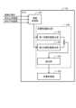
図4は、本実施形態におけるアクティブサスペンション装置1のECU24の機能を示した機能ブロック図である。Figure 4 is a functional block diagram showing the functions of the
ECU24は、前輪プレビュー制御部241、プレビュー制御成功判定部242(判定部)、および後輪制御部243を備えて構成されている。後輪制御部243は、成功時処理部244と、失敗時処理部245とを備えて構成されている。ECU24は、プレビューセンサ3よって検出された路面100の高さの変位によってサスペンションのストローク(ダンパ22の長さ)を制御する(図3参照)。The
前輪プレビュー制御部241は、プレビューセンサ3から、前輪の車輪16前方の路面100の高さを取得する。前輪プレビュー制御部241は、プレビューセンサ3により検出された路面100の高さの変位によって前輪のサスペンションのストロークを変更し、プレビュー制御を実行する。前輪プレビュー制御部241は、例えば、取得した路面100の高さに応じて、対応する前輪のダンパ22の長さを調整する。The front wheel
すなわち、車両10における右側の前輪は、右側の路面100の高さに応じて、右側の前輪のダンパ22の長さを調整する。一方、車両10における左側の前輪は、左側の路面100の高さに応じて、左側の前輪のダンパ22の長さを調整する。That is, for the right front wheel of the vehicle 10, the length of the damper 22 for the right front wheel is adjusted according to the height of the road surface 100 on the right side. On the other hand, for the left front wheel of the vehicle 10, the length of the damper 22 for the left front wheel is adjusted according to the height of the road surface 100 on the left side.
プレビュー制御成功判定部242(判定部)は、前輪プレビュー制御部241により前輪のダンパ22の長さ(サスペンションのストローク)を変更して、当該ストロークの制御によるプレビュー制御が成功であるか否かを判定する。The preview control success determination unit 242 (determination unit) changes the length of the front wheel damper 22 (suspension stroke) using the front wheel
成功であるか否か(失敗)の判定として、プレビュー制御成功判定部242は、例えば、前輪のプレビュー制御がオフの場合の動作を仮定した理論車両モデルと、実ボディ動作とを比較する。これにより、プレビュー制御成功判定部242は、当該実ボディ動作の値が理論車両モデルの値よりも悪化している場合、前輪のプレビュー制御が失敗であると判定する。具体的には、プレビュー制御成功判定部242は、段差を乗り越え時に位置しているときの加速度センサ29の値が、所定の値以上である場合に、プレビュー制御が失敗であると判定することができる。To determine whether or not the preview control is successful (failure), the preview control
なお、プレビュー制御成功判定部242は、理論車両モデルと実ボディ動作との比較に限定されない。例えば、加速度センサ29に絶対値がある場合、プレビュー制御成功判定部242は、その加速度センサ29の所定の閾値以上の場合にプレビュー制御が失敗であると判定して、後輪のプレビュー制御を解除(すなわち、OFF)にしてもよい。Note that the preview control
後輪制御部243は、プレビュー制御成功判定部242の判定結果に基づいて、対応する後輪のサスペンションのストロークを制御する。後輪制御部243は、例えば、ダンパ22の長さを調節することにより、サスペンションのストロークを制御する。The rear
例えば、プレビュー制御成功判定部242により前輪のプレビュー制御が成功した旨の判定が行われた場合、後輪制御部243は、成功時処理部244により、対応する後輪に対し、プレビュー制御とスカイフック制御とを実行する。For example, if the preview control
一方、プレビュー制御成功判定部242により前輪のプレビュー制御が失敗した旨の判定が行われた場合、後輪制御部243は、失敗時処理部245により、対応する後輪に対し、プレビュー制御を解除して、スカイフック制御を実行する。なお、スカイフック制御は、スカイフック理論に基づいて、ばね上要素(車体12)の振動をダンパ22の長さを能動的に調整することによって制振する制御であるが、スカイフック制御ではプレビューセンサ3の情報は用いない。On the other hand, if the preview control
このように、本実施形態に係るアクティブサスペンション装置1のECU24は、前輪のプレビュー制御が失敗した場合、対応する後輪のサスペンションに対し、プレビュー制御を解除して、スカイフック制御を実行する。つまり、前輪でプレビュー制御を失敗していれば後輪でも失敗する可能性高く、本実施形態では、失敗の可能性の高い後輪でのプレビュー制御を避けることができる。In this way, if the preview control of the front wheels fails, the
これにより、アクティブサスペンション装置1は、後輪では、スカイフック制御だけを行う。よって、車両に乗っている人の乗り心地がかえって悪くなる恐れを防止することができる。すなわち、乗り心地が悪くなる可能性が高いプレビュー制御を後輪では行わないで済むので、乗り心地の悪化を回避できる。As a result, the active suspension system 1 only performs skyhook control on the rear wheels, which prevents the ride comfort of the vehicle occupants from becoming worse. In other words, preview control, which is likely to make the ride uncomfortable, does not need to be performed on the rear wheels, so deterioration of the ride comfort can be avoided.
また、後輪制御部243は、前輪のプレビュー制御が成功した場合の後輪のスカイフック制御について、前輪のプレビュー制御が失敗した場合の後輪のスカイフック制御よりもゲインを上げる(変更する)ことができる。すなわち、後輪制御部243は、前輪のプレビュー制御が成功した場合の後輪のスカイフック制御に対し、重みを増すことができる。The rear
補足すると、前輪のプレビュー制御の成功時は、プレビュー制御で賄いきれない部分に対してスカイフック制御を行うため、スカイフック制御の割合が失敗時よりも少ない(前輪のプレビュー制御の失敗時は、後輪は全てスカイフック制御である)。従って、前輪のプレビュー制御の成功時について、後輪のスカイフック制御のゲインを上げる(変更する)ことで、後輪について、必要な制御量を出力する。ここで、本実施形態の後輪制御部243は、前輪のプレビュー制御が成功した場合の後輪のスカイフック制御について、前輪のプレビュー制御が失敗した場合の後輪のスカイフック制御よりもゲインを上げることに限定されるものではなく、例えば、ゲインを下げるように変更してもよい。Additionally, when the preview control of the front wheels is successful, skyhook control is performed for the portion that cannot be covered by the preview control, so the proportion of skyhook control is less than when it fails (when the preview control of the front wheels fails, all of the rear wheels are skyhook controlled). Therefore, when the preview control of the front wheels is successful, the gain of the skyhook control of the rear wheels is increased (changed) to output the required control amount for the rear wheels. Here, the rear
なお、後輪制御部243は、後輪ごとに、対応する前輪のプレビュー制御の判定結果に基づいて、後輪のサスペンションのストロークを制御する。これにより、後輪制御部243は、左右の両前輪のプレビュー制御が失敗した場合、左右の後輪の両方ともプレビュー制御を解除して、スカイフック制御を実行する。一方、例えば、右の前輪のプレビュー制御が失敗した場合は、右の後輪のプレビュー制御を解除して、右の後輪については、スカイフック制御を実行する。The rear
このように、本実施形態に係るアクティブサスペンション装置1は、前輪でプレビュー制御を実行するとともに、プレビュー制御が失敗した場合でも、対応する後輪に対して、スカイフック制御を実行することができるので、車両に乗っている人の乗り心地が悪くなる恐れを防止することができる。In this way, the active suspension device 1 according to this embodiment performs preview control on the front wheels, and even if the preview control fails, it can perform skyhook control on the corresponding rear wheels, thereby preventing the risk of passengers in the vehicle becoming uncomfortable.
次に、プレビュー制御とスカイフック制御に係る荷重制御について説明する。Next, we will explain the load control related to preview control and skyhook control.
<ECUの荷重制御>
図5は、本発明の実施形態に係るアクティブサスペンション装置1に備わるECU24の荷重制御について説明した説明図である。なお、ECU24の荷重制御は、図4に示したアクティブサスペンション装置1のECU24の機能の一例であり、これに限定されるものではない。 <Load control by ECU>
5 is an explanatory diagram illustrating the load control of the
図5に示すECU24は、情報取得部251、目標荷重算出部256、および荷重制御部255を備えて構成されている。また、目標荷重算出部256は、第1目標荷重算出部252、第2目標荷重算出部253、および統合部254を備えて構成されている。The
情報取得部251は、車両10の進行方向の走行路面に係る路面状態の時系列情報として、路面100の高さ(相対路面高)の情報を取得する。相対路面高の情報は、例えば、車両10の相対路面高をプレビューセンサ3により検出する。なお、相対路面高とは、路面100に対するばね上要素(車体12)の相対的な高さを意味する。The
また、情報取得部251は、一例として、ばね上加速度、ばね下加速度の各々の時系列情報を取得する。ばね上加速度の情報は、車両10のばね上要素(車体12)に設けた加速度センサ29の検出値に基づいて取得する。また、ばね下加速度の情報は、車両10のばね下要素に設けられる加速度センサ(図示せず)の検出値に基づいて取得する。なお、ばね下加速度は、任意の構成要素であるため、情報取得部251は、ばね下加速度を取得しても、または取得しなくても、特に、限定されるものではない。In addition, the
情報取得部251は、取得した路面100の高さ(相対路面高)、ばね上加速度、およびばね下加速度に基づいて、「ばね上速度」、「絶対路面高」を推定する。情報取得部251は、例えば、現在の車両状態として、「ばね上速度」を推定する。また、「絶対路面高」とは、路面100に対するばね上要素(車体12)の絶対的な高さを意味する。The
この場合、情報取得部251は、例えば、ばね上加速度、ばね下加速度、および路面100の高さ(相対路面高)の各々の時系列情報に基づいて、車体振動に伴う誤差を含む相対路面高から同誤差分を差し引いた「絶対路面高」を推定する。なお、情報取得部251は、例えば、ジャイロセンサを用いることにより、そのジャイロセンサから「ばね上速度」および「ばね下速度」を直接取得してもよい。In this case, the
情報取得部251で推定された「ばね上速度」(車両状態量)の情報は、第1目標荷重算出部252に送出される。一方、情報取得部251で推定された「絶対路面高」の情報は、第2目標荷重算出部253に送出される。The "sprung speed" (vehicle state quantity) information estimated by the
次に、目標荷重算出部256は、情報取得部251で取得した各種の情報に基づいて、ダンパ22に係る減衰動作及び伸縮動作の目標値である統合目標荷重を、演算により算出する。Next, the target
目標荷重算出部256の第1目標荷重算出部252は、情報取得部251で推定された「ばね上速度」(車両状態量)に基づいて、スカイフック制御に係る第1目標荷重を算出する。具体的には、例えば、第1目標荷重算出部252は、スカイフック理論に基づく制御則を用いて、推定された「ばね上速度」(車両状態量)に対してスカイフック減衰係数を乗算することで第1目標荷重を算出する。第1目標荷重算出部252で算出された第1目標荷重は、統合部254に送られる。The first target
目標荷重算出部256の第2目標荷重算出部253は、情報取得部251で推定された「絶対路面高」(実際の路面高)に基づいて、プレビュー制御に係る第2目標荷重を算出する。具体的には、例えば、第2目標荷重算出部253は、スカイフック理論に基づく制御則を用いて、「絶対路面高」(実際の路面高さ)に対してプレビュー制御ゲインを乗算することで第2目標荷重を算出する。第2目標荷重算出部253で算出された第2目標荷重は、統合部254に送られる。The second target
目標荷重算出部256の統合部254は、第1目標荷重算出部252で算出された第1目標荷重と、第2目標荷重算出部253で算出された第2目標荷重とを加算する統合を行う。統合部254で統合された統合目標荷重の情報は、荷重制御部255に送られる。The
荷重制御部255は、目標荷重算出部256で算出した統合目標荷重を実現可能な目標電流値を算出する。荷重制御部255は、例えば、電動モータ(図示せず)に係るモータ電流を、算出した目標電流値に追従させるように、複数の各ダンパ22のそれぞれに備わる電動モータの駆動制御を行う。The
<アクティブサスペンション装置の動作>
次に、本実施形態に係るアクティブサスペンション装置1の動作について説明する。図6は、本実施形態に係るアクティブサスペンション装置1の動作を示したフローチャートである。適宜、図1から図4を参照しながら説明する。 <Operation of active suspension device>
Next, the operation of the active suspension system 1 according to this embodiment will be described. Fig. 6 is a flow chart showing the operation of the active suspension system 1 according to this embodiment. The explanation will be given with reference to Figs. 1 to 4 as needed.
まず、プレビューセンサ3は、走行中の車両10において、前輪(車輪16)前方の路面100の高さを検出する(ステップS11)。First, the
ECU24の前輪プレビュー制御部241は、プレビューセンサ3から、前輪前方の路面100の高さを取得する。前輪プレビュー制御部241は、プレビューセンサ3により検出された路面100の高さの変位によって、前輪のサスペンションのストロークを変更し、プレビュー制御を実行する(ステップS12)。The front wheel
前輪プレビュー制御部241は、例えば、取得した路面100の高さに応じて、対応する車輪16のダンパ22の長さを調整する。この場合、車両10における右側の車輪16は、右側の路面100の高さに応じて、右側の車輪16のダンパ22の長さを調整する。一方、車両10における左側の車輪16は、左側の路面100の高さに応じて、左側の車輪16のダンパ22の長さを調整する。The front wheel
プレビュー制御成功判定部242は、前輪プレビュー制御部241により前輪のダンパ22の長さ(サスペンションのストローク)を変更して、当該ストロークの制御によるプレビュー制御が成功であるか否か(失敗)を判定する(ステップS13)。The preview control
プレビュー制御成功判定部242は、例えば、車輪16のプレビュー制御がオフの場合の動作を仮定した理論車両モデルと、実ボディ動作とを比較する。プレビュー制御成功判定部242は、当該実ボディ動作の値が、理論車両モデルの値よりも悪化している場合、車輪16のプレビュー制御が失敗であると判定する。具体的には、プレビュー制御成功判定部242は、段差を乗り越え時に位置しているときの加速度センサ29の値が、所定の値以上である場合に、プレビュー制御が失敗であると判定する。The preview control
なお、プレビュー制御成功判定部242は、理論車両モデルと実ボディ動作との比較に限定されない。例えば、加速度センサ29に絶対値がある場合、プレビュー制御成功判定部242は、その加速度センサ29の所定の閾値以上の場合にプレビュー制御が失敗であると判定して、後輪のプレビュー制御を解除(すなわち、OFF)にしてもよい。Note that the preview control
プレビュー制御成功判定部242により車輪16のプレビュー制御が成功した旨の判定が行われた場合(ステップS13のYes)、後輪制御部243は、成功時処理部244により、対応する後輪に対し、ダンパ22の長さを調節するプレビュー制御とスカイフック制御とを実行する(ステップS14)。If the preview control
一方、プレビュー制御成功判定部242により車輪16のプレビュー制御が失敗した旨の判定が行われた場合(ステップS13のNo)、後輪制御部243は、失敗時処理部245により、対応する後輪に対し、プレビュー制御を解除して、スカイフック制御を実行する(ステップS15)。On the other hand, if the preview control
このように、本実施形態に係るアクティブサスペンション装置1のECU24は、前輪のプレビュー制御が失敗した場合に、後輪のサスペンションに対し、プレビュー制御を解除して、スカイフック制御を実行する。これにより、アクティブサスペンション装置1は、スカイフック制御によりばね上振動をゼロにすることができるので、車両10に乗っている人の乗り心地が悪くなる恐れを防止することができる。In this way, if the preview control of the front wheels fails, the
<本実施形態の効果>
図7(a)は、前輪のプレビュー制御が成功したときに、ECU24の後輪制御部243が、成功時処理部244により、後輪を制御する概念を示す説明図である。図7(b)は、前輪のプレビュー制御が失敗したときに、ECU24の後輪制御部243が、失敗時処理部245により、後輪を制御する概念を示す説明図である。 <Effects of this embodiment>
Fig. 7(a) is an explanatory diagram showing the concept of the rear
ECU24は、プレビュー制御成功判定部242により、前輪にプレビュー制御を行った後、当該前輪でのプレビュー制御が成功であるか失敗であるかを判定する。後輪制御部243は、プレビュー制御成功判定部242の判定結果に基づいて、その前輪に対応する後輪のサスペンションのストロークを制御する。After performing preview control on the front wheels, the
図7(a)に示すように、プレビュー制御成功判定部242により右側の前輪タイヤ14のプレビュー制御が成功した旨の判定が行われた場合、後輪制御部243は、成功時処理部244により、前輪と同じ側である右側の後輪(後輪タイヤ54)に対し、サスペンションのストロークを制御するプレビュー制御とスカイフック制御とを実行する。As shown in FIG. 7(a), when the preview control
図7(a)の左側の図では、右側の前輪タイヤ14が突起104を乗り越えた後、プレビュー制御成功判定部242により、前輪プレビュー制御部241のプレビュー制御が成功したことを示している。プレビュー制御が成功したことにより、図7(a)の右側の図では、後輪制御部243は、成功時処理部244により、右側の後輪(後輪タイヤ54)に対し、プレビュー制御とスカイフック制御とを実行している。In the diagram on the left side of FIG. 7(a), after the right front tire 14 has gone over the protrusion 104, the preview control
一方、図7(b)に示すように、プレビュー制御成功判定部242により右側の前輪タイヤ14のプレビュー制御が失敗した旨の判定が行われた場合、後輪制御部243は、失敗時処理部245により、右側の後輪(後輪タイヤ54)に対し、プレビュー制御を解除して、スカイフック制御を実行する。On the other hand, as shown in FIG. 7(b), if the preview control
図7(b)の左側の図では、右側の前輪タイヤ14が突起104を乗り越えた後、プレビュー制御成功判定部242により、前輪プレビュー制御部241のプレビュー制御が失敗したことを示している。プレビュー制御が失敗したことにより、図7(b)の右側の図では、後輪制御部243は、失敗時処理部245により、前輪と同じ側である右側の後輪(後輪タイヤ54)に対し、プレビュー制御を解除するとともに、スカイフック制御を実行している。In the diagram on the left side of FIG. 7(b), after the right front tire 14 goes over the protrusion 104, the preview control
後輪制御部243は、失敗時処理部245により、スカイフック制御を実行して、従来のサスペンション制御、すなわち、プレビュー制御を行わないスカイフック制御だけでのサスペンション制御を実行できる。これにより、ECU24は、右側の後輪タイヤ54に生じる振動を吸収することができる。ちなみに、前輪のプレビュー制御の失敗は、例えば、突起104を検出できなかったなどの場合に起こる。The rear
なお、前記のように、後輪制御部243は、前輪タイヤ14のプレビュー制御が成功した場合の後輪タイヤ54のスカイフック制御を、前輪タイヤ14のプレビュー制御が失敗した場合の後輪タイヤ54のスカイフック制御よりもゲインを上げることができる。このように、成功時に後輪のスカイフック制御のゲインを上げることで必要な制御量を出力することができ、後輪タイヤ54のダンパ22は、ゲインを上げない場合よりも、車両10の振動を吸収することができる。As described above, the rear
以上説明したように、第1の実施形態に係るアクティブサスペンション装置1は、プレビューセンサ3と、ECU24とを備えて構成されている。ECU24は、前輪プレビュー制御部241、プレビュー制御成功判定部242、および後輪制御部243を備えて構成されている。As described above, the active suspension device 1 according to the first embodiment is configured to include the
後輪制御部243は、プレビュー制御成功判定部242により前輪のプレビュー制御が成功した旨の判定が行われた場合、対応する後輪に対して、成功時処理部244により、サスペンションのストロークを制御するプレビュー制御とスカイフック制御とを実行する。一方、プレビュー制御成功判定部242により前輪のプレビュー制御が失敗した旨の判定が行われた場合、後輪制御部243は、対応する後輪に対して、失敗時処理部245により、プレビュー制御を解除して、スカイフック制御を実行する。When the preview control
これにより、第1の実施形態に係るアクティブサスペンション装置1は、プレビュー制御成功判定部242により前輪のプレビュー制御が失敗した旨の判定が行われても、車両10に乗っている人の乗り心地が悪くなる恐れを防止することができる。As a result, the active suspension device 1 according to the first embodiment can prevent passengers in the vehicle 10 from experiencing poor riding comfort even if the preview control
なお、本実施形態では、プレビュー制御成功判定部242において、前輪プレビュー制御部241によるプレビュー制御を判定していたが、プレビュー制御の判定は、特に上述した内容に限定されるものではない。In this embodiment, the preview control
例えば、プレビューセンサ3がビニール袋やペットボトルなどの物体を検出して、路面100の高さを検出すると、前輪プレビュー制御部241は、ビニール袋やペットボトルなどの物体の高さに基づいて、前輪のダンパ22の長さ(サスペンションのストローク)を変更する。この場合、前輪タイヤ14がビニール袋やペットボトルなどの物体を踏むとその物体は変形するため、プレビューセンサ3で検出した路面100の高さは、誤検出となる。For example, when the
本発明の実施形態は、このような場合でも、プレビュー制御が失敗したと判定することができる。すなわち、プレビューセンサ3がビニール袋やペットボトルなどの物体により路面100の高さを誤検出すると、その物体が変形するとともに前輪のダンパ22の長さが不適切な長さとなるため、車体12のばね上要素のばね上加速度、またはばね下要素のばね下加速度が変化する。Even in such a case, the embodiment of the present invention can determine that the preview control has failed. That is, if the
そのため、プレビュー制御成功判定部242は、加速度センサの所定の閾値を相対的に低く設定することにより、プレビュー制御が成功であるか否かの判定を細かく実施することができる。これにより、ビニール袋やペットボトルなどの物体により路面100の高さを誤検出しても、後輪制御部243は、失敗時処理部245により後輪タイヤ54に対し、スカイフック制御のみを実行することができる。Therefore, the preview control
1 アクティブサスペンション装置
3 プレビューセンサ(路面状態検出手段)
10 車両
12 車体
14 前輪タイヤ
16 車輪
18 サスペンションアーム
20 スプリング
22 ダンパ
24 ECU
241 前輪プレビュー制御部
242 プレビュー制御成功判定部(判定部)
243 後輪制御部
244 成功時処理部
245 失敗時処理部
251 情報取得部
252 第1目標荷重算出部
253 第2目標荷重算出部
254 統合部
255 荷重制御部
256 目標荷重算出部
26 車輪速センサ
29 加速度センサ
54 後輪タイヤ
56 車輪
100 路面
102,104 突起1
10 vehicle 12 vehicle body 14 front tire 16 wheel 18 suspension arm 20 spring 22
241 Front wheel
243 Rear
Claims (5)
Translated fromJapanese前記路面状態検出手段により検出された前記路面の高さの変位によってサスペンションのストロークを制御して、プレビュー制御を実行する制御部と、を有するアクティブサスペンション装置であって、
前記制御部は、
前記路面状態検出手段により検出された前記路面の高さの変位によって前輪のサスペンションのストロークを変更し、プレビュー制御を実行する前輪プレビュー制御部と、
前記前輪プレビュー制御部により前記前輪のサスペンションのストロークを変更して、当該ストロークの制御によるプレビュー制御が成功であるか否かを判定する判定部と、
前記判定部の判定結果に基づいて、対応する後輪のサスペンションのストロークを制御する後輪制御部と、備え、
前記後輪制御部は、
前記判定部により前記前輪のプレビュー制御が成功した旨の判定が行われた場合、対応する後輪に対し、サスペンションのストロークを制御するプレビュー制御とスカイフック制御とを実行し、
前記判定部により前記前輪のプレビュー制御が失敗した旨の判定が行われた場合、対応する後輪に対し、プレビュー制御を解除して、スカイフック制御を実行する、
ことを特徴とするアクティブサスペンション装置。 a road surface condition detection means for detecting the height of the road surface in front of the wheels;
a control unit that controls a stroke of a suspension according to a change in height of the road surface detected by the road surface condition detection means to perform a preview control,
The control unit is
a front wheel preview control unit that changes a stroke of a front wheel suspension according to the change in height of the road surface detected by the road surface condition detection means and executes a preview control;
a determination unit that changes a stroke of the suspension of the front wheels by the front wheel preview control unit and determines whether or not the preview control by controlling the stroke is successful;
a rear wheel control unit that controls a suspension stroke of a corresponding rear wheel based on a determination result of the determination unit;
The rear wheel control unit is
When the determination unit determines that the preview control of the front wheel is successful, a preview control for controlling a suspension stroke and a skyhook control are executed for the corresponding rear wheel;
When the determination unit determines that the preview control of the front wheel has failed, the preview control is released for the corresponding rear wheel, and skyhook control is executed.
1. An active suspension device comprising:
前記前輪のプレビュー制御が成功した場合の前記後輪のスカイフック制御を、前記前輪のプレビュー制御が失敗した場合の前記後輪のスカイフック制御からゲインを変更する、
ことを特徴とする請求項1に記載のアクティブサスペンション装置。 The rear wheel control unit is
changing a gain of the skyhook control of the rear wheels when the preview control of the front wheels is successful from a gain of the skyhook control of the rear wheels when the preview control of the front wheels is unsuccessful;
2. The active suspension system according to claim 1.
前記前輪のプレビュー制御がオフの場合の動作を仮定した理論車両モデルと、実ボディ動作とを比較して、当該実ボディ動作の値が前記理論車両モデルの値よりも悪化している場合、前記前輪のプレビュー制御が失敗であると判定する、
ことを特徴とする請求項1または2に記載のアクティブサスペンション装置。 The determination unit is
comparing an actual body motion with a theoretical vehicle model that assumes motion when the preview control of the front wheels is off, and determining that the preview control of the front wheels has failed if the value of the actual body motion is worse than the value of the theoretical vehicle model;
3. The active suspension device according to claim 1 or 2.
段差を乗り越え時に位置しているときの加速度センサの値が、所定の値以上である場合、前記失敗であると判定する、
ことを特徴とする請求項3に記載のアクティブサスペンション装置。 The determination unit is
When a value of the acceleration sensor when the obstacle is overcome is equal to or greater than a predetermined value, the obstacle is determined to have failed.
4. The active suspension system according to claim 3.
Priority Applications (3)
| Application Number | Priority Date | Filing Date | Title |
|---|---|---|---|
| JP2021182452AJP7489367B2 (en) | 2021-11-09 | 2021-11-09 | Active suspension device and vehicle equipped with active suspension device |
| CN202211286648.0ACN116101003A (en) | 2021-11-09 | 2022-10-20 | Active suspension device and vehicle provided with same |
| US17/972,069US12030358B2 (en) | 2021-11-09 | 2022-10-24 | Active suspension device and vehicle with active suspension device |
Applications Claiming Priority (1)
| Application Number | Priority Date | Filing Date | Title |
|---|---|---|---|
| JP2021182452AJP7489367B2 (en) | 2021-11-09 | 2021-11-09 | Active suspension device and vehicle equipped with active suspension device |
Publications (2)
| Publication Number | Publication Date |
|---|---|
| JP2023070344A JP2023070344A (en) | 2023-05-19 |
| JP7489367B2true JP7489367B2 (en) | 2024-05-23 |
Family
ID=86230112
Family Applications (1)
| Application Number | Title | Priority Date | Filing Date |
|---|---|---|---|
| JP2021182452AActiveJP7489367B2 (en) | 2021-11-09 | 2021-11-09 | Active suspension device and vehicle equipped with active suspension device |
Country Status (3)
| Country | Link |
|---|---|
| US (1) | US12030358B2 (en) |
| JP (1) | JP7489367B2 (en) |
| CN (1) | CN116101003A (en) |
Families Citing this family (3)
| Publication number | Priority date | Publication date | Assignee | Title |
|---|---|---|---|---|
| US20220396113A1 (en)* | 2021-06-11 | 2022-12-15 | Hak Soo Kim | Advanced electronically controlled air suspension (ecas) system with image sensors |
| CN115703318B (en)* | 2021-08-09 | 2025-08-01 | 本田技研工业株式会社 | Suspension device |
| DE102021129355B4 (en)* | 2021-11-11 | 2023-05-25 | Audi Aktiengesellschaft | Method for operating a chassis of a motor vehicle and motor vehicle |
Citations (2)
| Publication number | Priority date | Publication date | Assignee | Title |
|---|---|---|---|---|
| US20170240018A1 (en) | 2016-02-19 | 2017-08-24 | GM Global Technology Operations LLC | Methods and systems for optimizing vehicle ride using road preview |
| WO2020158314A1 (en) | 2019-01-28 | 2020-08-06 | 日立オートモティブシステムズ株式会社 | Vehicle behavior device |
Family Cites Families (10)
| Publication number | Priority date | Publication date | Assignee | Title |
|---|---|---|---|---|
| JPH0596922A (en) | 1991-05-16 | 1993-04-20 | Toyota Motor Corp | Control device for active suspension |
| JPH04372415A (en)* | 1991-06-19 | 1992-12-25 | Toyota Motor Corp | Active suspension control device |
| US6209887B1 (en)* | 1999-04-05 | 2001-04-03 | Meritor Heavy Vehicle Systems, Llc | Microprocessor controlled vehicle suspension |
| US6311110B1 (en)* | 1999-06-17 | 2001-10-30 | Lord Corporation | Adaptive off-state control method |
| US8311704B2 (en)* | 2007-03-20 | 2012-11-13 | Honda Motor Co., Ltd. | Control apparatus of variable damping force damper |
| DE112012006147B8 (en)* | 2012-03-29 | 2018-09-06 | Toyota Jidosha Kabushiki Kaisha | Road surface condition determination means |
| JP5958542B2 (en)* | 2012-08-02 | 2016-08-02 | トヨタ自動車株式会社 | Road surface condition acquisition device and suspension system |
| JP5941886B2 (en)* | 2013-08-30 | 2016-06-29 | 本田技研工業株式会社 | Suspension control device |
| US9902401B2 (en)* | 2015-05-10 | 2018-02-27 | Mobileye Vision Technologies Ltd. | Road profile along a predicted path |
| WO2018155541A1 (en)* | 2017-02-24 | 2018-08-30 | 日立オートモティブシステムズ株式会社 | Vehicle behavior control device |
- 2021
- 2021-11-09JPJP2021182452Apatent/JP7489367B2/enactiveActive
- 2022
- 2022-10-20CNCN202211286648.0Apatent/CN116101003A/enactivePending
- 2022-10-24USUS17/972,069patent/US12030358B2/enactiveActive
Patent Citations (2)
| Publication number | Priority date | Publication date | Assignee | Title |
|---|---|---|---|---|
| US20170240018A1 (en) | 2016-02-19 | 2017-08-24 | GM Global Technology Operations LLC | Methods and systems for optimizing vehicle ride using road preview |
| WO2020158314A1 (en) | 2019-01-28 | 2020-08-06 | 日立オートモティブシステムズ株式会社 | Vehicle behavior device |
Also Published As
| Publication number | Publication date |
|---|---|
| CN116101003A (en) | 2023-05-12 |
| US12030358B2 (en) | 2024-07-09 |
| JP2023070344A (en) | 2023-05-19 |
| US20230141330A1 (en) | 2023-05-11 |
Similar Documents
| Publication | Publication Date | Title |
|---|---|---|
| JP7489367B2 (en) | Active suspension device and vehicle equipped with active suspension device | |
| CN107651026B (en) | Method and device for controlling or adjusting a cab mount | |
| US12083845B2 (en) | Suspension control apparatus | |
| US8311704B2 (en) | Control apparatus of variable damping force damper | |
| CN113386515A (en) | Method for controlling the vertical vibration damping of at least one wheel of a vehicle and vehicle with at least one wheel capable of vertical vibration damping | |
| JP7223798B2 (en) | ACTIVE SUSPENSION DEVICE AND SUSPENSION CONTROL DEVICE | |
| JP7214776B2 (en) | ACTIVE SUSPENSION DEVICE AND SUSPENSION CONTROL DEVICE | |
| JP7561287B2 (en) | Suspension Systems and Controllers | |
| JP5211674B2 (en) | Vehicle suspension system | |
| JP5144289B2 (en) | Control device for damping force variable damper | |
| JP5162283B2 (en) | Control device and control method for damping force variable damper | |
| JP5135023B2 (en) | Suspension characteristic control device | |
| JP4788675B2 (en) | Vehicle suspension system | |
| US20250128562A1 (en) | Vehicle control device and vehicle control system | |
| JP4960715B2 (en) | Vehicle equipped with damper with variable damping force | |
| CN114193993A (en) | Suspension system with optimized position sensitive damping and system and method for optimizing same | |
| JP2009078657A (en) | Vehicle suspension system | |
| JP4836648B2 (en) | Vehicle equipped with damper with variable damping force | |
| WO2024127990A1 (en) | Sensor abnormality detecting device | |
| JP2009137342A (en) | Control device for damping force variable damper | |
| JP4987762B2 (en) | Control device for damping force variable damper | |
| WO2019003893A1 (en) | Suspension control device | |
| JP2020142537A (en) | Suspension system | |
| JP4664759B2 (en) | Stroke sensor abnormality determination device | |
| JP5131685B2 (en) | Control device for damping force variable damper |
Legal Events
| Date | Code | Title | Description |
|---|---|---|---|
| A621 | Written request for application examination | Free format text:JAPANESE INTERMEDIATE CODE: A621 Effective date:20231128 | |
| TRDD | Decision of grant or rejection written | ||
| A977 | Report on retrieval | Free format text:JAPANESE INTERMEDIATE CODE: A971007 Effective date:20240422 | |
| A01 | Written decision to grant a patent or to grant a registration (utility model) | Free format text:JAPANESE INTERMEDIATE CODE: A01 Effective date:20240423 | |
| A61 | First payment of annual fees (during grant procedure) | Free format text:JAPANESE INTERMEDIATE CODE: A61 Effective date:20240513 | |
| R150 | Certificate of patent or registration of utility model | Ref document number:7489367 Country of ref document:JP Free format text:JAPANESE INTERMEDIATE CODE: R150 |