JP7488339B2 - Reflectance factor correction method using dual polarization variable based bright band detection result and recording medium and device for performing the same - Google Patents
Reflectance factor correction method using dual polarization variable based bright band detection result and recording medium and device for performing the sameDownload PDFInfo
- Publication number
- JP7488339B2 JP7488339B2JP2022535114AJP2022535114AJP7488339B2JP 7488339 B2JP7488339 B2JP 7488339B2JP 2022535114 AJP2022535114 AJP 2022535114AJP 2022535114 AJP2022535114 AJP 2022535114AJP 7488339 B2JP7488339 B2JP 7488339B2
- Authority
- JP
- Japan
- Prior art keywords
- bright band
- value
- altitude
- elevation angle
- membership function
- Prior art date
- Legal status (The legal status is an assumption and is not a legal conclusion. Google has not performed a legal analysis and makes no representation as to the accuracy of the status listed.)
- Active
Links
Images


Classifications
- G—PHYSICS
- G01—MEASURING; TESTING
- G01S—RADIO DIRECTION-FINDING; RADIO NAVIGATION; DETERMINING DISTANCE OR VELOCITY BY USE OF RADIO WAVES; LOCATING OR PRESENCE-DETECTING BY USE OF THE REFLECTION OR RERADIATION OF RADIO WAVES; ANALOGOUS ARRANGEMENTS USING OTHER WAVES
- G01S7/00—Details of systems according to groups G01S13/00, G01S15/00, G01S17/00
- G01S7/02—Details of systems according to groups G01S13/00, G01S15/00, G01S17/00 of systems according to group G01S13/00
- G01S7/024—Details of systems according to groups G01S13/00, G01S15/00, G01S17/00 of systems according to group G01S13/00 using polarisation effects
- G01S7/025—Details of systems according to groups G01S13/00, G01S15/00, G01S17/00 of systems according to group G01S13/00 using polarisation effects involving the transmission of linearly polarised waves
- G—PHYSICS
- G01—MEASURING; TESTING
- G01S—RADIO DIRECTION-FINDING; RADIO NAVIGATION; DETERMINING DISTANCE OR VELOCITY BY USE OF RADIO WAVES; LOCATING OR PRESENCE-DETECTING BY USE OF THE REFLECTION OR RERADIATION OF RADIO WAVES; ANALOGOUS ARRANGEMENTS USING OTHER WAVES
- G01S7/00—Details of systems according to groups G01S13/00, G01S15/00, G01S17/00
- G01S7/02—Details of systems according to groups G01S13/00, G01S15/00, G01S17/00 of systems according to group G01S13/00
- G01S7/41—Details of systems according to groups G01S13/00, G01S15/00, G01S17/00 of systems according to group G01S13/00 using analysis of echo signal for target characterisation; Target signature; Target cross-section
- G01S7/411—Identification of targets based on measurements of radar reflectivity
- G01S7/412—Identification of targets based on measurements of radar reflectivity based on a comparison between measured values and known or stored values
- G—PHYSICS
- G01—MEASURING; TESTING
- G01S—RADIO DIRECTION-FINDING; RADIO NAVIGATION; DETERMINING DISTANCE OR VELOCITY BY USE OF RADIO WAVES; LOCATING OR PRESENCE-DETECTING BY USE OF THE REFLECTION OR RERADIATION OF RADIO WAVES; ANALOGOUS ARRANGEMENTS USING OTHER WAVES
- G01S13/00—Systems using the reflection or reradiation of radio waves, e.g. radar systems; Analogous systems using reflection or reradiation of waves whose nature or wavelength is irrelevant or unspecified
- G01S13/88—Radar or analogous systems specially adapted for specific applications
- G01S13/95—Radar or analogous systems specially adapted for specific applications for meteorological use
- G—PHYSICS
- G01—MEASURING; TESTING
- G01S—RADIO DIRECTION-FINDING; RADIO NAVIGATION; DETERMINING DISTANCE OR VELOCITY BY USE OF RADIO WAVES; LOCATING OR PRESENCE-DETECTING BY USE OF THE REFLECTION OR RERADIATION OF RADIO WAVES; ANALOGOUS ARRANGEMENTS USING OTHER WAVES
- G01S7/00—Details of systems according to groups G01S13/00, G01S15/00, G01S17/00
- G01S7/02—Details of systems according to groups G01S13/00, G01S15/00, G01S17/00 of systems according to group G01S13/00
- G01S7/024—Details of systems according to groups G01S13/00, G01S15/00, G01S17/00 of systems according to group G01S13/00 using polarisation effects
- G—PHYSICS
- G01—MEASURING; TESTING
- G01S—RADIO DIRECTION-FINDING; RADIO NAVIGATION; DETERMINING DISTANCE OR VELOCITY BY USE OF RADIO WAVES; LOCATING OR PRESENCE-DETECTING BY USE OF THE REFLECTION OR RERADIATION OF RADIO WAVES; ANALOGOUS ARRANGEMENTS USING OTHER WAVES
- G01S7/00—Details of systems according to groups G01S13/00, G01S15/00, G01S17/00
- G01S7/02—Details of systems according to groups G01S13/00, G01S15/00, G01S17/00 of systems according to group G01S13/00
- G01S7/28—Details of pulse systems
- G01S7/285—Receivers
- G01S7/292—Extracting wanted echo-signals
- G01S7/2923—Extracting wanted echo-signals based on data belonging to a number of consecutive radar periods
- G01S7/2926—Extracting wanted echo-signals based on data belonging to a number of consecutive radar periods by integration
- G—PHYSICS
- G01—MEASURING; TESTING
- G01S—RADIO DIRECTION-FINDING; RADIO NAVIGATION; DETERMINING DISTANCE OR VELOCITY BY USE OF RADIO WAVES; LOCATING OR PRESENCE-DETECTING BY USE OF THE REFLECTION OR RERADIATION OF RADIO WAVES; ANALOGOUS ARRANGEMENTS USING OTHER WAVES
- G01S7/00—Details of systems according to groups G01S13/00, G01S15/00, G01S17/00
- G01S7/02—Details of systems according to groups G01S13/00, G01S15/00, G01S17/00 of systems according to group G01S13/00
- G01S7/28—Details of pulse systems
- G01S7/285—Receivers
- G01S7/292—Extracting wanted echo-signals
- G01S7/2923—Extracting wanted echo-signals based on data belonging to a number of consecutive radar periods
- G01S7/2927—Extracting wanted echo-signals based on data belonging to a number of consecutive radar periods by deriving and controlling a threshold value
- Y—GENERAL TAGGING OF NEW TECHNOLOGICAL DEVELOPMENTS; GENERAL TAGGING OF CROSS-SECTIONAL TECHNOLOGIES SPANNING OVER SEVERAL SECTIONS OF THE IPC; TECHNICAL SUBJECTS COVERED BY FORMER USPC CROSS-REFERENCE ART COLLECTIONS [XRACs] AND DIGESTS
- Y02—TECHNOLOGIES OR APPLICATIONS FOR MITIGATION OR ADAPTATION AGAINST CLIMATE CHANGE
- Y02A—TECHNOLOGIES FOR ADAPTATION TO CLIMATE CHANGE
- Y02A90/00—Technologies having an indirect contribution to adaptation to climate change
- Y02A90/10—Information and communication technologies [ICT] supporting adaptation to climate change, e.g. for weather forecasting or climate simulation
Landscapes
- Engineering & Computer Science (AREA)
- Radar, Positioning & Navigation (AREA)
- Remote Sensing (AREA)
- Physics & Mathematics (AREA)
- Computer Networks & Wireless Communication (AREA)
- General Physics & Mathematics (AREA)
- Electromagnetism (AREA)
- Radar Systems Or Details Thereof (AREA)
Description
Translated fromJapanese本発明は二重偏波変数基盤明るい帯探知結果を利用した反射度補正方法、これを遂行するための記録媒体および装置に関し、さらに詳細にはファジィ論理と偏波消滅度を利用して明るい帯を探知し、反射度見かけプロファイルの生成を通じて反射度補正係数を算出して明るい帯による反射度過大観測を補正する技術に関する。The present invention relates to a method for correcting reflectivity using the results of bright band detection based on dual polarization parameters, and a recording medium and device for performing the method. More specifically, the present invention relates to a technology for detecting bright bands using fuzzy logic and polarization extinction rate, and correcting over-observation of reflectivity due to bright bands by calculating reflectivity correction coefficients through the generation of an apparent reflectivity profile.
明るい帯は、レーダビームが降雪粒子が0℃高度を通過しながら降雨粒子に変わる融解層を通過して反射度Zが過大観測される現象をいう。降雪粒子は0℃付近で溶け始め、誘電率の変化によってZが高くなる。The bright bands indicate a phenomenon in which the radar beam passes through a melting layer where snow particles turn into rain particles as they pass through 0°C altitude, resulting in an over-measured reflectivity Z. Snow particles begin to melt near 0°C, and Z increases due to a change in dielectric constant.
明るい帯によるZ過大観測は、Zに基づいた降水量推定時に過大推定を引き起こすため、正確な降水推定のためには明るい帯を探知し補正しなければならない。Over-observation of Z due to bright bands will cause overestimation when estimating precipitation based on Z, so the bright bands must be detected and corrected for accurate precipitation estimation.
単偏波レーダを利用した研究は殆どZプロファイルから明るい帯を探知した。Z鉛直構造に基づいた明るい帯の探知は、非気象エコー(地形エコーなど)が混在され明るい帯がレーダを中心に同心円の形態で現れない低高度角資料の明るい帯を探知するのに限界がある。また、夏場を除いて地上の近くに現れる明るい帯は全体の構造を観測することができないため活用が制限的であるという問題がある。Most studies using single-polarized radar have detected bright bands from Z profiles. Detection of bright bands based on Z vertical structure has limitations in detecting bright bands in low altitude angle data where non-meteorological echoes (terrain echoes, etc.) are mixed in and the bright bands do not appear in the form of concentric circles centered on the radar. In addition, there is a problem that the use of bright bands that appear near the ground except in summer is limited because the entire structure cannot be observed.
本発明の技術的課題はこのような点に鑑みたもので、本発明の目的は二重偏波変数基盤明るい帯探知結果を利用した反射度補正方法を提供することである。The technical objective of the present invention is to provide a method for correcting reflectivity using bright band detection results based on dual polarization parameters.
本発明の他の目的は、前記二重偏波変数基盤明るい帯探知結果を利用した反射度補正方法を遂行するためのコンピュータプログラムが記録された記録媒体を提供することである。Another object of the present invention is to provide a recording medium having a computer program recorded thereon for performing a reflectance correction method using the results of the dual polarization variable-based bright band detection.
本発明のさらに他の目的は、前記二重偏波変数基盤明るい帯探知結果を利用した反射度補正方法を遂行するための装置を提供することである。Another object of the present invention is to provide an apparatus for performing a reflectance correction method using the results of the dual polarization variable based bright band detection.
前記の本発明の目的を具現するための一実施例に係る二重偏波変数基盤明るい帯探知結果を利用した反射度補正方法は、二重偏波変数の観測誤差を補正して偏波消滅度を算出する前処理段階;特定高度角資料から生成された準-鉛直分布から抽出された明るい帯の高度を利用して、明るい帯と非明るい帯領域の二重偏波変数を分析して各特性変数の所属関数および加重値を算出するファジィ分類器生成段階;高度角別にファジィ分類器と偏波消滅度を利用して明るい帯を探知する明るい帯探知段階;および高度角別に明るい帯領域の反射度資料を平均して生成した反射度見かけプロファイルを利用して算出した補正係数に基づいて探知された明るい帯領域の反射度過大観測を補正する反射度補正段階;を含む。The reflectivity correction method using the bright band detection result based on the dual polarization variables according to one embodiment of the present invention for realizing the above-mentioned object includes a pre-processing step of correcting the observation error of the dual polarization variables and calculating the polarization extinction degree; a fuzzy classifier generation step of analyzing the dual polarization variables of the bright band and non-bright band areas using the altitude of the bright band extracted from the quasi-vertical distribution generated from the specific altitude angle data and calculating the belonging function and weight value of each characteristic variable; a bright band detection step of detecting the bright band using the fuzzy classifier and the polarization extinction degree according to the altitude angle; and a reflectivity correction step of correcting the over-observation of the reflectivity of the detected bright band area based on a correction coefficient calculated using the reflectivity apparent profile generated by averaging the reflectivity data of the bright band area according to the altitude angle.
本発明の実施例で、前記前処理段階は、反射度および差等反射度に対して遮蔽による電力損失を補正する段階;反射度および差等反射度に対して降雨減衰補正を遂行する段階;信号対雑音比(SNR)を利用して交差相関係数を補正する段階;および交差相関係数および差等反射度に基づいて偏波消滅度を算出する段階;を含むことができる。In an embodiment of the present invention, the pre-processing step may include a step of correcting power loss due to occlusion for reflectivity and differential reflectivity; a step of performing rain attenuation correction for reflectivity and differential reflectivity; a step of correcting cross-correlation coefficients using a signal-to-noise ratio (SNR); and a step of calculating polarization extinction based on the cross-correlation coefficients and differential reflectivity.
本発明の実施例で、前記ファジィ分類器生成段階は、一定高度角以上の特定高度角資料から準-鉛直分布を生成する段階;生成された準-鉛直分布から明るい帯の高度を抽出する段階;抽出された明るい帯の高度を基準として明るい帯と非明るい帯領域を区分する段階;および正規化された頻度分布から各特性変数の所属関数(MF)を算出し、所属関数から加重値を決定する段階;を含むことができる。In an embodiment of the present invention, the fuzzy classifier generation step may include a step of generating a quasi-vertical distribution from specific altitude angle data equal to or greater than a certain altitude angle; a step of extracting the altitude of a bright band from the generated quasi-vertical distribution; a step of distinguishing bright band and non-bright band regions based on the altitude of the extracted bright band; and a step of calculating a membership function (MF) of each characteristic variable from the normalized frequency distribution and determining a weight value from the membership function.
本発明の実施例で、前記明るい帯探知段階は、各特性変数の加重値を利用して観測資料の明るい帯による汚染度を表す総所属値を算出する段階;総所属値と偏波消滅度を利用して明るい帯を判別する段階;各高度角で方位角を基準として各セクター別総所属値を高度により平均して生成した総所属値プロファイルおよびレーダビームの中心温度を高度により平均した温度平均プロファイルを利用して誤探知された領域を除去する段階;および中間値フィルタを適用して明るい帯探知結果を平滑化する段階;を含むことができる。In an embodiment of the present invention, the bright band detection step may include a step of calculating a total belonging value representing the degree of contamination by bright bands in the observation data using weighted values of each characteristic variable; a step of identifying bright bands using the total belonging value and the degree of polarization extinction; a step of removing falsely detected areas using a total belonging value profile generated by averaging the total belonging values for each sector by altitude based on the azimuth angle at each altitude angle and a temperature average profile obtained by averaging the central temperature of the radar beam by altitude; and a step of smoothing the bright band detection results by applying a median filter.
本発明の実施例で、前記明るい帯を判別する段階は、交差相関係数が予め設定された第1しきい値以下である場合、総所属値が予め設定された第2しきい値を超過する場合、および交差相関係数が前記第1しきい値を超過する場合、偏波消滅度が予め設定された第3しきい値以上の場合、明るい帯の候補として区別する段階;を含むことができる。In an embodiment of the present invention, the step of identifying the bright band may include the step of distinguishing as a candidate bright band when the cross-correlation coefficient is equal to or less than a preset first threshold, when the total membership value exceeds a preset second threshold, when the cross-correlation coefficient exceeds the first threshold, and when the degree of polarization extinction is equal to or greater than a preset third threshold.
本発明の実施例で、前記明るい帯を判別する段階は、明るい帯の候補のうちレーダから距離によりSNRが予め設定された第4しきい値を超過するか、反射度が予め設定された第5しきい値を超過するか、レーダビーム上端部の温度が予め設定された第6しきい値未満であるかまたはレーダビーム下端部の温度が予め設定された第7しきい値を超過する場合、明るい帯として判別する段階;をさらに含むことができる。In an embodiment of the present invention, the step of identifying the bright band may further include a step of identifying a bright band candidate as a bright band if the SNR exceeds a preset fourth threshold depending on the distance from the radar, the reflectivity exceeds a preset fifth threshold, the temperature of the upper end of the radar beam is less than a preset sixth threshold, or the temperature of the lower end of the radar beam exceeds a preset seventh threshold.
本発明の実施例で、前記誤探知された領域を除去する段階は、各高度角で方位角を基準として各セクター別総所属値を高度により平均して総所属値プロファイルおよびレーダビームの中心温度を高度により平均して温度平均プロファイルを生成する段階;予め設定した値以上の高高度角に対して平均総所属値が最大である高度を基準高度に設定して、平均総所属値が予め設定された第8しきい値未満となる最初の高度を明るい帯の上限および下限高度に設定する段階;および予め設定した値未満の低高度角に対して平均温度が0℃である高度を基準高度に設定して、明るい帯の上限および下限高度を基準高度より予め設定した高度だけ高いか低く、総所属値の平均が前記第8しきい値未満である高度に設定する段階;を含むことができる。In an embodiment of the present invention, the step of removing the false detection area may include the steps of: averaging the total belonging values for each sector by altitude based on the azimuth angle at each altitude angle to generate a total belonging value profile and averaging the central temperature of the radar beam by altitude to generate a temperature average profile; setting the altitude at which the average total belonging value is maximum for high altitude angles equal to or greater than a preset value as the reference altitude, and setting the first altitude at which the average total belonging value is less than the preset 8th threshold as the upper and lower limit altitudes of the bright band; and setting the altitude at which the average temperature is 0°C for low altitude angles less than the preset value as the reference altitude, and setting the upper and lower limit altitudes of the bright band as altitudes that are higher or lower than the reference altitude by a preset altitude and where the average of the total belonging value is less than the 8th threshold.
本発明の実施例で、前記誤探知された領域を除去する段階は、高度角にかかわらず平均温度が一定範囲内である高度内で、平均総所属値の最大値が前記第8しきい値未満であり特定距離で平均温度が零下である場合、上限高度を再設定する段階;をさらに含むことができる。In an embodiment of the present invention, the step of removing the falsely detected area may further include the step of resetting the upper limit altitude if the maximum average total belonging value is less than the eighth threshold value and the average temperature is below zero at a specific distance within an altitude where the average temperature is within a certain range regardless of the altitude angle.
本発明の実施例で、前記反射度補正段階は、各高度角別降水エコー対比明るい帯エコーの比が一定の比以上である場合、明るい帯領域の反射度資料を平均して反射度見かけプロファイルを生成する段階;見かけプロファイルから明るい帯上端部-最頂点、最頂点-下端部、上端部-下端部に対する高度による反射度傾きを算出する段階;明るい帯として探知された領域に対して明るい帯の最頂点を基準として反射度補正係数を計算する段階;算出された補正係数に基づいて観測された反射度と補正後の反射度の差値である反射度補正値を算出する段階;および算出された補正値を観測された反射度に適用する段階;を含むことができる。In an embodiment of the present invention, the reflectivity correction step may include the steps of: averaging the reflectivity data of the bright band region to generate an apparent reflectivity profile when the ratio of the bright band echo to the precipitation echo at each altitude angle is equal to or greater than a certain ratio; calculating the reflectivity gradient according to altitude for the top-to-peak, top-to-bottom, and top-to-bottom of the bright band from the apparent profile; calculating a reflectivity correction coefficient based on the top of the bright band for the area detected as a bright band; calculating a reflectivity correction value, which is the difference between the observed reflectivity and the corrected reflectivity based on the calculated correction coefficient; and applying the calculated correction value to the observed reflectivity.
本発明の実施例で、前記二重偏波変数基盤明るい帯探知結果を利用した反射度補正方法は、補正された反射度および反射度補正値を保存する結果保存段階;をさらに含むことができる。In an embodiment of the present invention, the reflectance correction method using the dual polarization parameter-based bright band detection result may further include a result storage step of storing the corrected reflectance and the reflectance correction value.
前記本発明の他の目的を具現するための一実施例に係るコンピュータで読み取り可能な保存媒体には、前記二重偏波変数基盤明るい帯探知結果を利用した反射度補正方法を遂行するためのコンピュータプログラムが記録されている。In one embodiment of the present invention, a computer-readable storage medium for implementing another object of the present invention has recorded thereon a computer program for performing a reflectivity correction method using the results of the dual polarization variable-based bright band detection.
前記本発明のさらに他の目的を具現するための一実施例に係る二重偏波変数基盤明るい帯探知結果を利用した反射度補正装置は、二重偏波変数観測誤差を補正して偏波消滅度を算出する前処理部;特定高度角資料から生成された準-鉛直分布から抽出された明るい帯の高度を利用して各特性変数の所属関数および加重値を生成するファジィ分類器生成部;高度角別に総所属値と偏波消滅度を利用して明るい帯を探知する明るい帯探知部;および高度角別に明るい帯領域の反射度資料を平均して生成した反射度の見かけプロファイルを利用して算出した補正係数に基づいて探知された明るい帯領域の反射度過大観測を補正する反射度補正部;を含む。The reflectivity correction device using the bright band detection result based on dual polarization variables according to one embodiment of the present invention for implementing yet another object of the present invention includes a pre-processing unit that corrects the dual polarization variable observation error and calculates the polarization extinction degree; a fuzzy classifier generation unit that generates the membership function and weight value of each characteristic variable using the altitude of the bright band extracted from the quasi-vertical distribution generated from the specific altitude angle data; a bright band detection unit that detects the bright band using the total membership value and the polarization extinction degree by altitude angle; and a reflectivity correction unit that corrects the over-observation of the reflectivity of the detected bright band area based on a correction coefficient calculated using the apparent reflectivity profile generated by averaging the reflectivity data of the bright band area by altitude angle.
本発明の実施例で、前記前処理部は、反射度および差等反射度に対して遮蔽による電力損失を補正するビーム遮蔽補正部;反射度および差等反射度に対して降雨減衰補正を遂行する降雨減衰補正部;信号対雑音比(SNR)を利用して交差相関係数を補正するρhv補正部;および交差相関係数および差等反射度に基づいて偏波消滅度を算出するDr計算部;を含むことができる。In an embodiment of the present invention, the pre-processing unit may include a beam occlusion correction unit that corrects power loss due to occlusion for reflectivity and differential reflectivity; a rain attenuation correction unit that performs rain attenuation correction for reflectivity and differential reflectivity; a ρhv correction unit that corrects a cross-correlation coefficient using a signal-to-noise ratio (SNR); and a Dr calculation unit that calculates a polarization extinction rate based on the cross-correlation coefficient and differential reflectivity.
本発明の実施例で、前記ファジィ分類器生成部は、一定高度角以上の特定高度角資料から準-鉛直分布を生成するQVP生成部;生成された準-鉛直分布から明るい帯の高度を抽出する明るい帯高度抽出部;明るい帯の高度を基準として明るい帯と非明るい帯領域を区分する明るい帯区別部;および正規化された頻度分布から各特性変数の所属関数(MF)を算出し、所属関数から加重値を決定する加重値決定部;を含むことができる。In an embodiment of the present invention, the fuzzy classifier generation unit may include a QVP generation unit that generates a quasi-vertical distribution from specific altitude angle data equal to or greater than a certain altitude angle; a bright band height extraction unit that extracts the height of a bright band from the generated quasi-vertical distribution; a bright band discrimination unit that distinguishes bright band and non-bright band regions based on the height of the bright band; and a weight determination unit that calculates the membership function (MF) of each characteristic variable from the normalized frequency distribution and determines a weight from the membership function.
本発明の実施例で、前記明るい帯探知部は、各特性変数の加重値を利用して観測資料の明るい帯による汚染度を表す総所属値を算出する総所属値算出部;総所属値と偏波消滅度を利用して明るい帯を判別する明るい帯判別部;各高度角で方位角を基準として各セクター別総所属値を高度により平均して生成した総所属値プロファイルおよびレーダビームの中心温度を高度により平均した温度平均プロファイルを利用して誤探知された領域を除去する誤探知除去部;および中間値フィルタを適用して明るい帯探知結果を平滑化する平滑化部;を含むことができる。In an embodiment of the present invention, the bright band detection unit may include a total belonging value calculation unit that calculates a total belonging value representing the degree of contamination by bright bands in the observation data using weighted values of each characteristic variable; a bright band discrimination unit that discriminates bright bands using the total belonging value and the degree of polarization extinction; a false detection removal unit that removes false detection areas using a total belonging value profile generated by averaging the total belonging values for each sector by altitude based on the azimuth angle at each altitude angle and a temperature average profile that averages the central temperature of the radar beam by altitude; and a smoothing unit that smoothes the bright band detection results by applying a median filter.
本発明の実施例で、前記明るい帯判別部は、交差相関係数が予め設定された第1しきい値以下である場合、総所属値が予め設定された第2しきい値を超過する場合、および交差相関係数が前記第1しきい値を超過する場合、偏波消滅度が予め設定された第3しきい値以上の場合、明るい帯の候補として区別することができる。In an embodiment of the present invention, the bright band discrimination unit can distinguish as a bright band candidate when the cross-correlation coefficient is equal to or less than a predetermined first threshold, when the total membership value exceeds a predetermined second threshold, when the cross-correlation coefficient exceeds the first threshold, and when the degree of polarization extinction is equal to or greater than a predetermined third threshold.
本発明の実施例で、前記明るい帯判別部は、明るい帯の候補のうちレーダから距離によりSNRが予め設定された第4しきい値を超過するか、反射度が予め設定された第5しきい値を超過するか、レーダビーム上端部の温度が予め設定された第6しきい値未満であるかまたはレーダビーム下端部の温度が予め設定された第7しきい値を超過する場合、明るい帯として判別することができる。In an embodiment of the present invention, the bright band discrimination unit can discriminate a bright band candidate as being a bright band if the SNR exceeds a preset fourth threshold depending on the distance from the radar, the reflectivity exceeds a preset fifth threshold, the temperature of the upper end of the radar beam is less than a preset sixth threshold, or the temperature of the lower end of the radar beam exceeds a preset seventh threshold.
本発明の実施例で、前記誤探知除去部は、各高度角で方位角を基準として各セクター別総所属値を高度により平均して総所属値プロファイルおよびレーダビームの中心温度を高度により平均して温度平均プロファイルを生成し、予め設定した値以上の高高度角に対して平均総所属値が最大である高度を基準高度に設定して、平均総所属値が予め設定された第8しきい値未満となる最初の高度を明るい帯の上限および下限高度に設定し、予め設定した値未満の低高度角に対して平均温度が0℃である高度を基準高度に設定して、明るい帯の上限および下限高度を基準高度より予め設定した高度だけ高いか低く、総所属値の平均が前記第8しきい値未満である高度に設定し、高度角にかかわらず平均温度が一定範囲内である高度内で、平均総所属値の最大値が前記第8しきい値未満で平均温度が零下である場合、上限高度を再設定することができる。In an embodiment of the present invention, the false detection removal unit averages the total belonging values for each sector by altitude at each altitude angle based on the azimuth angle to generate a total belonging value profile and averages the central temperature of the radar beam by altitude to generate a temperature average profile, sets the altitude at which the average total belonging value is maximum for high altitude angles equal to or greater than a preset value as the reference altitude, sets the first altitude at which the average total belonging value is less than a preset 8th threshold as the upper and lower altitudes of the bright band, sets the altitude at which the average temperature is 0°C for low altitude angles less than a preset value as the reference altitude, sets the upper and lower altitudes of the bright band to altitudes that are higher or lower than the reference altitude by a preset altitude and where the average of the total belonging values is less than the 8th threshold, and can reset the upper limit altitude if the maximum average total belonging value is less than the 8th threshold and the average temperature is below zero within an altitude where the average temperature is within a certain range regardless of the altitude angle.
本発明の実施例で、前記反射度補正部は、各高度角別降水エコー対比明るい帯エコーの比が一定の比以上である場合、明るい帯領域の反射度資料を平均して反射度見かけプロファイルを生成するプロファイル生成部;見かけプロファイルから明るい帯上端部-最頂点、最頂点-下端部、上端部-下端部に対する高度による反射度傾きを算出する変化率算出部;明るい帯として探知された領域に対して明るい帯の最頂点を基準として反射度補正係数を計算する補正係数算出部;算出された補正係数に基づいて観測された反射度と補正後の反射度の差値である反射度補正値を算出する補正値算出部;および算出された補正値を観測された反射度に適用する補正値適用部;を含むことができる。In an embodiment of the present invention, the reflectivity correction unit may include a profile generation unit that averages the reflectivity data of the bright band region to generate an apparent reflectivity profile when the ratio of the bright band echo to the precipitation echo at each altitude angle is equal to or greater than a certain ratio; a change rate calculation unit that calculates the reflectivity slope according to altitude for the upper end-peak, peak-bottom end, and upper end-bottom end of the bright band from the apparent profile; a correction coefficient calculation unit that calculates a reflectivity correction coefficient based on the peak of the bright band for the area detected as a bright band; a correction value calculation unit that calculates a reflectivity correction value, which is the difference between the observed reflectivity and the corrected reflectivity based on the calculated correction coefficient; and a correction value application unit that applies the calculated correction value to the observed reflectivity.
本発明の実施例で、前記二重偏波変数基盤明るい帯探知結果を利用した反射度補正装置は、補正された反射度および反射度補正値を保存する結果保存部;をさらに含むことができる。In an embodiment of the present invention, the reflectance correction device using the dual polarization variable based bright band detection result may further include a result storage unit that stores the corrected reflectance and the reflectance correction value.
このような二重偏波変数基盤明るい帯探知結果を利用した反射度補正方法によると、明るい帯の二重偏波変数特性を分析してファジィ論理によって明るい帯汚染度を算出し、探知された明るい帯に対する反射度見かけプロファイルを利用して反射度補正係数を算出する。したがって、レーダボリューム資料の格子基盤明るい帯を探知して過大観測された反射度資料を補正することができ、補正された反射度を利用して降水量推定正確度を向上させることができる。According to this reflectivity correction method using the results of bright band detection based on dual polarization variables, the characteristics of the dual polarization variables of the bright band are analyzed to calculate the degree of bright band pollution using fuzzy logic, and a reflectivity correction coefficient is calculated using the apparent reflectivity profile for the detected bright band. Therefore, it is possible to detect bright bands based on the grid of radar volume data to correct over-observed reflectivity data, and the accuracy of precipitation estimation can be improved using the corrected reflectivity.
後述する本発明に対する詳細な説明は、本発明が実施され得る特定の実施例を例示として図示する添付図面を参照する。これら実施例は当業者が本発明を実施できるように充分かつ詳細に説明される。本発明の多様な実施例は互いに異なるが相互に排他的である必要はないことが理解されるべきである。例えば、ここに記載されている特定の形状、構造および特性は、一実施例に関連して本発明の精神および範囲を逸脱することなく他の実施例で具現され得る。また、それぞれの開示された実施例内の個別構成要素の位置または配置は、本発明の精神および範囲を逸脱することなく変更され得る。したがって、後述する詳細な説明は限定的な意味ではなく、本発明の範囲は、適切に説明されるのであれば、その請求項が主張するものと均等なすべての範囲とともに添付された請求項によってのみ限定される。図面で類似する参照符号は多様な側面に亘って同一または類似する機能を指し示す。The following detailed description of the present invention will be made with reference to the accompanying drawings, which show, by way of example, specific embodiments in which the present invention may be practiced. These embodiments are described in sufficient detail to enable one skilled in the art to practice the present invention. It should be understood that the various embodiments of the present invention are different from one another but are not necessarily mutually exclusive. For example, specific shapes, structures and characteristics described herein in relation to one embodiment may be embodied in other embodiments without departing from the spirit and scope of the present invention. Also, the location or arrangement of individual components within each disclosed embodiment may be modified without departing from the spirit and scope of the present invention. Therefore, the following detailed description is not meant to be taken in a limiting sense, and the scope of the present invention is limited only by the appended claims, together with the full scope of equivalents to which such claims are entitled, if properly described. Like reference characters in the drawings indicate the same or similar functionality throughout the various aspects.
以下、図面を参照して本発明の好ましい実施例をより詳細に説明することにする。
図1は、本発明の一実施例に係る二重偏波変数基盤明るい帯探知結果を利用した反射度補正装置のブロック図である。DETAILED DESCRIPTION OF THE PREFERRED EMBODIMENTS Hereinafter, preferred embodiments of the present invention will be described in more detail with reference to the drawings.
FIG. 1 is a block diagram of a reflectance correction device using a bright band detection result based on dual polarization parameters according to an embodiment of the present invention.
本発明に係る二重偏波変数基盤明るい帯探知結果を利用した反射度補正装置(10、以下、装置)は、二重偏波変数で算出した偏波消滅度をファジィ分類器に追加して明るい帯を探知し、反射度見かけプロファイルを利用して明るい帯領域の過大観測された反射度補正技術を提供する。The reflectivity correction device (10, hereinafter referred to as the device) using the bright band detection results based on dual polarization variables according to the present invention detects bright bands by adding the polarization extinction degree calculated using dual polarization variables to a fuzzy classifier, and provides a technology for correcting over-observed reflectivity in bright band areas using the reflectivity apparent profile.
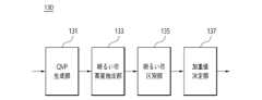
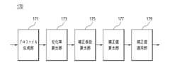
図1を参照すると、本発明に係る装置10は前処理部110、ファジィ分類器生成部130、明るい帯探知部150および反射度補正部170を含む。前記装置10は結果保存部190をさらに含むことができる。Referring to FIG. 1, the
本発明の前記装置10は二重偏波変数基盤明るい帯探知結果を利用した反射度補正を遂行するためのソフトウェア(アプリケーション)が設置されて実行され得、前記前処理部110、前記ファジィ分類器生成部130、前記明るい帯探知部150、前記反射度補正部170および前記結果保存部190の構成は、前記装置10で実行される前記二重偏波変数基盤明るい帯探知結果を利用した反射度補正を遂行するためのソフトウェアによって制御され得る。The
前記装置10は別途の端末であるかまたは端末の一部のモジュールであり得る。また、前記前処理部110、前記ファジィ分類器生成部130、前記明るい帯探知部150、前記反射度補正部170および前記結果保存部190の構成は統合モジュールで形成されるか、一つ以上のモジュールからなり得る。しかし、これとは反対に各構成は別途のモジュールからなってもよい。The
前記装置10は移動性を有するか固定され得る。前記装置10は、サーバー(server)またはエンジン(engine)の形態であり得、デバイス(device)、機構(apparatus)、端末(terminal)、UE(user equipment)、MS(mobile station)、無線機器(wireless device)、携帯機器(handheld device)等の他の用語で呼ばれ得る。The
前記装置10は運営体制(Operation System;OS)、すなわちシステムに基づいて多様なソフトウェアを実行するか製作することができる。前記運営体制はソフトウェアが装置のハードウェアを使用できるようにするためのシステムプログラムであって、アンドロイド(登録商標)OS、iOS、ウインドウモバイルOS、バダOS、シンビアンOS、ブラックベリーOSなどのモバイルコンピュータ運営体制およびウインドウ系列、リナックス(登録商標)系列、ユニックス系列、MAC、AIX、HP-UXなどのコンピュータ運営体制をすべて含むことができる。The
前記前処理部110は二重偏波変数の観測誤差を補正して偏波消滅度を算出する。The
融解層で溶けている降雪粒子をレーダが観測すると誘電率によってZが増加し、大気水象体の形に関連した差等反射度が増加する。レーダビームの観測ボリューム内大気水象体の種類の均質性に関連した交差相関係数(ρhv)、大気水象体の軸比(axis ratio)に関連した線形消滅度(linear depolarization ratio、LDR)も明るい帯探知に有用なレーダ観測変数である。When the radar observes snowflakes melting in the melting layer, Z increases due to the dielectric constant, and the differential reflectivity increases, which is related to the shape of the hydrometeor. The cross-correlation coefficient (ρhv ), which is related to the homogeneity of the hydrometeor types within the observation volume of the radar beam, and the linear depolarization ratio (LDR), which is related to the axis ratio of the hydrometeor, are also useful radar observation variables for bright band detection.
LDR変数観測のためには一つの偏波モードのみ送信する特別な観測戦略が要求されるので、水平偏波と垂直偏波を同時送受信(simultaneous transmission and receiving、STAR)する現業用二重偏波レーダはLDR資料を獲得できない。Because observing LDR variables requires a special observation strategy that transmits only one polarization mode, operational dual-polarized radars that simultaneously transmit and receive horizontal and vertical polarization (simultaneous transmission and receiving, STAR) cannot obtain LDR data.
最近、STARモードで運営されるレーダで観測可能な変数であるρhv、ZDR資料を利用して偏波消滅度(depolarization ratio、Dr)を算出することによって、LDR変数に代わって品質管理、明るい帯探知、ひょうの探知、降雪粒子の形の区分などに活用している。したがって、本発明はZ、ZDR、ρhv、Drをファジィ分類器の特性変数として使い、各変数に対して観測誤差を補正する前処理過程を遂行する。Recently, the depolarization ratio (Dr ) is calculated usingρhv andZDR data, which are observable variables of a radar operated in STAR mode, and is used in quality control, bright band detection, hail detection, classification of snow particle shapes, etc. instead of LDR variables. Therefore, the present invention uses Z,ZDR ,ρhv , andDr as characteristic variables of a fuzzy classifier and performs a pre-processing process to correct the observation error for each variable.
図2を参照すると、本発明の一実施例に係る前処理部110はビーム遮蔽補正部111、降雨減衰補正部113、ρhv補正部115およびDr計算部117を含むことができる。Referring to FIG. 2, the
前記ビーム遮蔽補正部111および前記降雨減衰補正部113は、レーダで観測された資料である反射度Zと差等反射度ZDRに対して部分ビーム遮蔽、降雨減衰による反射度損失を補正する。遮蔽率は遮蔽による電力損失率を意味し、水平に約30m解像度の数値標高モデル(digital elevation model、DEM)資料を利用して標準大気でのビーム屈折とガウシアンビームパターンを仮定して算出した(BBF=1は完全損失を意味する)。観測誤差別Z、ZDR補正値は以下の数式1および数式2のように計算され得る。The beam


ρhvはレーダ受信機、導波管、アンテナなどによる雑音の影響を受ける。前記ρhv補正部115は雑音によって偏向された(biased)ρhvを補正するために、以下の数式3のように信号対雑音比(signal to noise ratio、SNR)を利用することができる。ρhv is affected by noise from a radar receiver, a waveguide, an antenna, etc. The ρhv corrector 115 may use a signal to noise ratio (SNR) as shown in


Dr計算部117は交差相関係数および差等反射度に基づいて偏波消滅度を算出する。DrはSTARモードで運営されるレーダのρhvとZDR資料を利用して以下の数式4のように算出することができる。The Dr calculation unit 117 calculates the polarization extinction ratio based on the cross-correlation coefficient and the differential reflectivity.D r can be calculated using ρhv and ZDR data of the radar operated in the STAR mode as shown in


前記ファジィ分類器生成部130は、準-鉛直分布から抽出された明るい帯の高度内での二重偏波変数の分布を利用して加重値および所属関数を生成する。図3を参照すると、前記ファジィ分類器生成部130はQVP生成部131、明るい帯高度抽出部133、明るい帯区別部135および加重値決定部137を含むことができる。The fuzzy
一般的に、低高度角(例えば、0.7°)と高高度角(例えば、7.5°)に対するZ、ρhv映像を比較すると、高高度角ではZ、ρhv領域ですべて明るい帯の境界が明確に区分されるが、ρhv映像で明るい帯領域が反射度映像に比べて多少狭い。低高度角ではZ映像で明るい帯の境界を把握し難い反面、ρhv映像で明るい帯の境界が明確に現れる。Generally, when comparing Z,ρhv images for a low altitude angle (e.g., 0.7°) and a high altitude angle (e.g., 7.5°), the boundaries of the bright bands are clearly defined in the Z,ρhv regions at the high altitude angle, but the bright bands in theρhv image are somewhat narrower than those in the reflectivity image. At the low altitude angle, the boundaries of the bright bands are difficult to grasp in the Z image, but the boundaries of the bright bands are clearly visible in theρhv image.
前記QVP生成部131は明るい帯の形態がレーダを中心に同心円で現れる高高度角の資料を利用して、準-鉛直分布を生成して明るい帯と非明るい帯領域での特性変数を分析する。明るい帯特性分析結果に基づいてファジィ分類器生成のための訓練した資料として使うことができる。The
一実施例で、ファジィ分類器生成のための明るい帯特性値析のために、7°高度角資料から生成した準-鉛直分布(Quasi-Vertical Profile、QVP)を利用した。準-鉛直分布は、特定高度角で二重偏波変数を方位角方向に平均して降水システムの鉛直構造を分析する技術である。高い高度角を利用すれば、二重偏波変数の雑音を最小化して降水システムの鉛直構造分析に有利である。前記明るい帯高度抽出部133は各二重偏波変数に対する準-鉛直分布と座標系回転方法を利用して明るい帯を探知することができる。In one embodiment, a Quasi-Vertical Profile (QVP) generated from 7° altitude angle data is used to analyze bright band characteristics for generating a fuzzy classifier. Quasi-Vertical Profile is a technique for analyzing the vertical structure of a precipitation system by averaging dual polarization variables in the azimuth direction at a specific altitude angle. Using a high altitude angle is advantageous for analyzing the vertical structure of a precipitation system by minimizing noise in dual polarization variables. The bright band
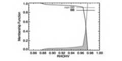
その結果、準-鉛直分布で二重偏波変数の最大値または最小値で明るい帯の最頂点(略4.5km)が位置した。明るい帯領域でρhvは0.97以下と低く、Drは-20.0dB以上の値を見せた。As a result, the apex of the bright band (approximately 4.5 km) was located at the maximum or minimum value of the dual polarization parameters in the quasi-vertical distribution. In the bright band region, ρhv was low at 0.97 or less, and Dr was greater than -20.0 dB.
例えば、前記明るい帯区別部135で明るい帯領域と非明るい帯領域の区分には、準-鉛直分布から抽出した明るい帯上端部、下端部を利用することができる。図4を参照すると、明るい帯領域は上端部~下端部(斜線を引いた領域)、非明るい帯領域は1.5km高度~下端部-5個のゲート、上端部+5個のゲート~最大距離までに設定した。For example, the bright
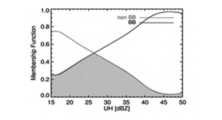
前記加重値決定部137は正規化された頻度分布から各特性変数の所属関数(MF)を算出し、所属関数から加重値を決定することができる。明るい帯特性変数別所属関数(membership function、MF)は以下の数式5のように正規化された頻度分布から算出することができる。The weight

ここで、F(i)は正規化された頻度分布、MF(i)は所属関数、iは特性変数(Z、ZDR、ρhv、Dr)を意味する。図5a~図5dは各変数別所属関数であり、所属関数の算出には総7個の層雲形降水の事例を利用した。各特性変数に対する加重値(weighting、W(i))は以下の数式6のように所属関数を利用して算出することができる。 Here, F(i) is the normalized frequency distribution, MF(i) is the membership function, and i is the characteristic variable (Z,ZDR ,ρhv ,Dr ). Figures 5a to 5d show the membership functions for each variable, and a total of seven cases of stratus precipitation were used to calculate the membership functions. The weighting value (weighting, W(i)) for each characteristic variable can be calculated using the membership function as shown in Equation 6 below.

ここで、Aiは明るい帯と非明るい帯の所属関数重なり領域の面積を意味する。Here, Ai means the area of the overlapping region of the bright and non-bright bands.
前記明るい帯探知部150はファジィ分類器およびセクター別総所属値/温度プロファイルを利用して明るい帯を探知する。The
図6は、ファジィ分類器を利用した明るい帯探知部に対するブロック図である。前記明るい帯探知部150は前記ファジィ分類器生成部130で生成されたファジィ分類器に基づいて観測資料の明るい帯による汚染度(総所属値)を算出し、総所属値とDrを利用して明るい帯を判別する。また、セクター基盤総所属値/温度平均プロファイルを利用して非気象エコー(青など)や低品質の観測資料によって明るい帯として誤探知された領域を除去し、中間値フィルタを適用して明るい帯探知結果を平滑化する。6 is a block diagram of a bright band detector using a fuzzy classifier. The
このために、前記明るい帯探知部150は総所属値算出部151、明るい帯判別部153、誤探知除去部155および平滑化部157を含むことができる。To this end, the bright
前記総所属値算出部151で総所属値(MVtotal)は以下の数式7のように各変数別加重値を利用して算出することができる。The total membership

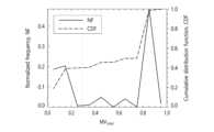
図7は総5個の降水事例に対する反射度準-鉛直分布で探知した明るい帯領域での総所属値分布である。明るい帯領域で総所属値はほとんど0.7~1.0の間に分布し、0.3を明るい帯探知のためのしきい値に決定した。0.3以下の値は準-鉛直分布内で高いρhvを見せた領域である。準-鉛直分布で明るい帯領域に含まれるがρhvが高い領域が存在する。Figure 7 shows the distribution of total membership values in the bright band detected by the reflectivity quasi-vertical profile for a total of five precipitation cases. In the bright band, the total membership values mostly ranged between 0.7 and 1.0, and 0.3 was determined as the threshold for bright band detection. Values below 0.3 are areas that show high ρhv in the quasi-vertical profile. There are areas with high ρhv that are included in the bright band in the quasi-vertical profile.
このような短所を解決するために、前記明るい帯判別部153は、ρhvが低い領域はファジィ分類器、ρhvが高い領域はDrを利用して明るい帯探知を探知する。In order to solve this problem, the
前記明るい帯判別部153は、格子基盤の明るい帯探知のために開発したファジィ分類器とDrしきい値を利用して明るい帯を探知する。この時、ρhv範囲によりファジィ論理とDrを適用する。The
例えば、ρhvが0.97以上である領域に対して総所属値が0.3以上、0.97を超過する領域に対してDrが-20.dB以上であれば、明るい帯に分類することができる。For example, if the total membership value is 0.3 or more for a region where ρhv is 0.97 or more, and if Dr is −20. dB or more for a region that exceeds 0.97, it can be classified as a bright band.
高度角によるSNRとρhv分布で、低高度角では低いSNR領域でビーム遮蔽によってρhvが低く、高高度角では降雪領域でρhvが低い。高度角が高いほど明るい帯の位置がレーダから近くなる。したがって、明るい帯とビーム遮蔽または降雪領域を区分するために、反射度が15dBZ以上であり、以下の数式8のようにレーダから距離によりSNRしきい値以上であれば、明るい帯として探知することができる。In the distribution of SNR and ρhv according to the altitude angle, ρhv is low due to beam blocking in the low SNR region at low altitude angles, and ρhv is low in the snowfall region at high altitude angles. The higher the altitude angle, the closer the bright band is to the radar. Therefore, in order to distinguish the bright band from the beam blocking or snowfall region, if the reflectivity is 15 dBZ or more and is above the SNR threshold according to the distance from the radar as shown in the following

ここで、rangeはレーダから距離(km)を意味する。Here, range means the distance (km) from the radar.
また、明るい帯可能域を制限するために、レーダビーム上端部(Tbtop)と下端部(Tbbot)の温度がそれぞれ10℃より低く、-10℃より高い時に明るい帯として探知することができる。Also, in order to limit the possible bright band area, the temperatures at the upper end (Tbtop ) and lower end (Tbbot ) of the radar beam can be detected as bright bands when they are lower than 10° C. and higher than −10° C., respectively.
前記誤探知除去部155はセクター基盤で総所属値/温度平均プロファイルを利用して誤探知された領域を除去する。The false

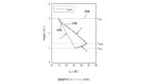
各高度角で方位角を基準として各セクター別総所属値プロファイルは総所属値を高度により平均して生成し、温度プロファイルはレーダビームの中心温度を高度により平均して生成する。The total belonging value profile for each sector is generated by averaging the total belonging values by altitude at each altitude angle based on the azimuth angle, and the temperature profile is generated by averaging the central temperature of the radar beam by altitude.
図8aはセクター別総所属値と温度平均プロファイル、図8bはセクター/ウインドウの大きさを示す。ウインドウの大きさは総所属値と温度平均プロファイル計算範囲を、セクターの大きさはしきい値適用範囲を意味する。明るい帯プロファイル生成時に観測ノイズを減らすために、セクターよりウインドウの大きさを広く設定することができる。Figure 8a shows the total membership value and temperature average profile by sector, and Figure 8b shows the sector/window size. The window size indicates the calculation range of the total membership value and temperature average profile, and the sector size indicates the threshold application range. In order to reduce observation noise when generating a bright band profile, the window size can be set wider than the sector.


これに伴い、青エコー以外にも低高度角で残っている非降水エコーを明るい帯として誤探知する現象を改善することができる。本発明は低品質の二重偏波変数は明るい帯を誤探知する原因となり、総所属値/温度平均プロファイルの適用を通じてこれを改善することができる。As a result, the phenomenon of misdetecting non-precipitation echoes remaining at low altitude angles as bright bands in addition to blue echoes can be improved. The present invention improves this by applying a total membership value/temperature average profile, which causes the misdetection of bright bands due to low-quality dual polarization variables.
前記平滑化部157は中間値フィルタを適用して明るい帯探知結果を平滑化する。ここで、中間値フィルタは点エコー形態の探知結果を除去するために適用する。The smoothing
例えば、該当ゲートを基準として、両側の方位角5個のゲート(3°x5gate)ウインドウ内でエコーが50%未満に存在すれば非明るい帯(NBB)に分類し、ウインドウ内でエコーが50%以上存在する場合、中間値で代替することができる。For example, if the echo is present in less than 50% of the azimuth gates (3° x 5 gates) on both sides of the gate, it is classified as a non-bright band (NBB), and if the echo is present in more than 50% of the window, it can be replaced with the intermediate value.
前記反射度補正部170は反射度見かけプロファイルを利用して算出した補正係数で明るい帯領域の反射度過大観測を補正する。The
図9は、前記明るい帯探知部150の明るい帯探知結果を利用した反射度補正部のブロック図である。図9を参照すると、前記反射度補正部170はプロファイル生成部171、変化率算出部173、補正係数算出部175、補正値算出部177および補正値適用部179を含む。Figure 9 is a block diagram of a reflectance correction unit that uses the bright band detection result of the bright
前記反射度補正部170は明るい帯によって汚染された領域の反射度を平均した見かけプロファイルから反射度変化率を算出して反射度補正係数を算出する。算出された補正係数を観測された反射度に適用して明るい帯による反射度過大観測を補正する。The
前記プロファイル生成部171は明るい帯による反射度過大観測を補正するために、反射度見かけプロファイル(Apparent vertical profile of reflectivity、AVPR)を生成する。AVPRは高度角別に明るい帯領域の反射度資料を平均して生成した。この時、該当距離で降水エコー対比明るい帯エコーの数が例えば、10%以上である場合にのみ反射度を平均することができる。The

前記変化率算出部173は明るい帯上端部-最頂点(α)、最頂点-下端部(β)、上端部-下端部(γ)に対する高度による反射度変化量(または反射度傾き)は最小自乗法を利用して算出することができる。The change


前記補正値適用部179は算出された補正値を観測された反射度に適用する。明るい帯の高度が方位角別に大きい差を見せる場合、CFをレーダ方位角を基準として各セクタ別にAVPRを生成することができ、同じ過程をセクター別に繰り返して反射度を補正することができる。The correction


本発明に係るレーダ2.1°、3.2°高度角資料に対する明るい帯補正結果、明るい帯によって過大観測された反射度領域で反射度補正後の反射度が減少したし、水平的に連続的な分布を見せた。As a result of bright band correction for radar data at 2.1° and 3.2° altitude angles according to the present invention, the reflectivity after reflectivity correction decreased in areas where the reflectivity was over-observed due to the bright band, and a horizontally continuous distribution was observed.

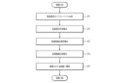
図11は、本発明の一実施例に係る二重偏波変数基盤明るい帯探知結果を利用した反射度補正方法のフローチャートである。Figure 11 is a flowchart of a reflectance correction method using dual polarization variable based bright band detection results according to one embodiment of the present invention.
本実施例に係る二重偏波変数基盤明るい帯探知結果を利用した反射度補正方法は、図1の装置10と実質的に同じ構成で進行され得る。したがって、図1の装置10と同じ構成要素は同じ図面番号を付与し、重複する説明は省略する。The reflectance correction method using the dual polarization variable based bright band detection result according to this embodiment can be carried out in substantially the same configuration as the
また、本実施例に係る二重偏波変数基盤明るい帯探知結果を利用した反射度補正方法は、二重偏波変数基盤明るい帯探知結果を利用した反射度補正を遂行するためのソフトウェア(アプリケーション)により実行され得る。In addition, the reflectance correction method using the dual polarization variable-based bright band detection results according to this embodiment can be executed by software (application) for performing reflectance correction using the dual polarization variable-based bright band detection results.
本発明は明るい帯の二重偏波変数特性を分析して、レーダボリューム資料で明るい帯によって汚染された領域を探知して過大観測されたZ資料を補正する。The present invention analyzes the dual polarization variable characteristics of bright bands to detect areas contaminated by bright bands in radar volume data and correct over-observed Z data.
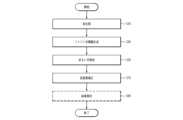
図11を参照すると、本実施例に係る二重偏波変数基盤明るい帯探知結果を利用した反射度補正方法は、二重偏波変数の観測誤差を補正し、偏波消滅度を算出する前処理過程を遂行する(段階S10)。Referring to FIG. 11, the reflectivity correction method using the bright band detection results based on dual polarization variables according to this embodiment performs a pre-processing process to correct the observation error of the dual polarization variables and calculate the polarization extinction rate (step S10).
これに伴い、前記前処理段階(段階S10)は、反射度および差等反射度に対して遮蔽による電力損失率を補正する段階、反射度および差等反射度に対して降雨減衰補正を遂行する段階、信号対雑音比(SNR)を利用して交差相関係数を補正する段階および交差相関係数および差等反射度に基づいて偏波消滅度を算出する段階を含むことができる。Accordingly, the pre-processing step (step S10) may include a step of correcting the power loss rate due to occlusion for the reflectivity and differential reflectivity, a step of performing rain attenuation correction for the reflectivity and differential reflectivity, a step of correcting the cross-correlation coefficient using the signal-to-noise ratio (SNR), and a step of calculating the degree of polarization extinction based on the cross-correlation coefficient and the differential reflectivity.
前処理が完了すると、特定高度角資料から生成された準-鉛直分布から抽出された明るい帯の高度を利用して、明るい帯と非明るい帯領域の二重偏波変数を分析して各特性変数の所属関数および加重値を算出してファジィ分類器を生成する(段階S30)。ここで、特性変数は反射度Z、差等反射度ZDR、交差相関係数(ρhv)、偏波消滅度(Dr)を含むことができる。After the pre-processing is completed, the altitude of the bright zone extracted from the quasi-vertical distribution generated from the specific altitude angle data is used to analyze the dual polarization variables of the bright zone and non-bright zone regions, and the membership function and weight value of each characteristic variable are calculated to generate a fuzzy classifier (step S30). Here, the characteristic variables can include reflectivity Z, differential reflectivity ZDR , cross-correlation coefficient (ρhv ), and polarization extinction ratio (Dr ).
ファジィ分類器を生成する段階(段階S30)は、一定高度角以上の特定高度角資料から準-鉛直分布を生成する段階、生成された準-鉛直分布から明るい帯の高度を抽出する段階、明るい帯の高度を基準として明るい帯と非明るい帯を区分する段階および正規化された頻度分布から各特性変数の所属関数(MF)を算出し、所属関数から加重値を決定する段階を含むことができる。The step of generating a fuzzy classifier (step S30) may include a step of generating a quasi-vertical distribution from specific altitude angle data equal to or greater than a certain altitude angle, a step of extracting the altitude of a bright band from the generated quasi-vertical distribution, a step of distinguishing bright bands from non-bright bands based on the altitude of the bright band, and a step of calculating a membership function (MF) for each characteristic variable from the normalized frequency distribution and determining a weight value from the membership function.
ファジィ分類器が生成されると、各特性変数の加重値、偏波消滅度およびセクター別総所属値と温度プロファイルを利用して明るい帯を探知する(段階S50)。Once the fuzzy classifier is generated, the bright zones are detected using the weights of each characteristic variable, the degree of polarization extinction, the total membership value by sector, and the temperature profile (step S50).
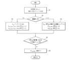
図12を参照すると、明るい帯を探知する段階(段階S50)は、まず各特性変数の加重値を利用して観測資料の明るい帯による汚染度を表す総所属値を算出する(段階S51)。Referring to FIG. 12, the step of detecting bright bands (step S50) first calculates a total belonging value that represents the degree of contamination of the observation data by bright bands using the weighted values of each characteristic variable (step S51).
総所属値と偏波消滅度を利用して明るい帯を判別する(段階S51)。例えば、交差相関係数が予め設定された第1しきい値(例えば、0.97)以下である場合(段階S52)、総所属値が予め設定された第2しきい値(例えば、0.3)を超過する場合(段階S53)および交差相関係数が前記第1しきい値を超過する場合(段階S52)、偏波消滅度が予め設定された第3しきい値(例えば、20)以上の場合、明るい帯の候補として区別することができる(段階S54)。その他の場合には非明るい帯として判別する(段階S57)。A bright band is identified using the total membership value and the polarization extinction degree (step S51). For example, if the cross-correlation coefficient is less than a first preset threshold value (e.g., 0.97) (step S52), if the total membership value exceeds a second preset threshold value (e.g., 0.3) (step S53), if the cross-correlation coefficient exceeds the first threshold value (step S52), or if the polarization extinction degree is greater than or equal to a third preset threshold value (e.g., 20), it can be distinguished as a candidate bright band (step S54). In other cases, it is distinguished as a non-bright band (step S57).
その後、明るい帯の候補のうち、レーダから距離によりSNRが予め設定された第4しきい値を超過するか、反射度が予め設定された第5しきい値(例えば、15.0)を超過するか、レーダビーム上端部の温度が予め設定された第6しきい値(例えば、10℃)未満であるかまたはレーダビーム下端部の温度が予め設定された第7しきい値(例えば、-10℃)を超過する場合(段階S55)、明るい帯として判別することができる(段階S56)。その他の場合には非明るい帯として判別する(段階S57)。Then, among the bright band candidates, if the SNR exceeds a preset fourth threshold depending on the distance from the radar, the reflectivity exceeds a preset fifth threshold (e.g., 15.0), the temperature of the upper end of the radar beam is less than a preset sixth threshold (e.g., 10°C), or the temperature of the lower end of the radar beam exceeds a preset seventh threshold (e.g., -10°C) (step S55), it can be identified as a bright band (step S56). Otherwise, it is identified as a non-bright band (step S57).
明るい帯を判別した後、各高度角で方位角を基準として、各セクター別総所属値を高度により平均して生成した総所属値プロファイルおよびレーダビームの中心温度を高度により平均した温度平均プロファイルを利用して誤探知された領域を除去することができる。After identifying the bright bands, it is possible to remove false detection areas using a total belonging value profile generated by averaging the total belonging values for each sector by altitude based on the azimuth angle at each altitude angle, and a temperature average profile generated by averaging the central temperature of the radar beam by altitude.
図13を参照すると、前記誤探知された領域を除去する段階は、各高度角でセクター別に総所属値を高度により平均して総所属値プロファイルおよびレーダビームの中心温度を高度により平均して温度平均プロファイルを生成する(段階S61)。Referring to FIG. 13, the step of removing the misdetected areas involves averaging the total belonging values by altitude for each sector at each altitude angle to generate a total belonging value profile, and averaging the central temperature of the radar beam by altitude to generate a temperature average profile (step S61).
予め設定した値(例えば、3°)以上の高高度角に対して(段階S62)、平均総所属値が最大である高度を基準高度に設定して、平均総所属値が予め設定された第8しきい値(例えば、0.2)未満となる最初の高度を明るい帯の上限および下限高度に設定することができる(段階S64)。For high altitude angles equal to or greater than a preset value (e.g., 3°) (step S62), the altitude at which the average total affiliation value is maximum can be set as the reference altitude, and the first altitude at which the average total affiliation value is less than a preset eighth threshold value (e.g., 0.2) can be set as the upper and lower altitude limits of the bright band (step S64).
予め設定した値未満の低高度角に対して(段階S62)、平均温度が0℃である高度を基準高度に設定して、明るい帯の上限および下限高度を基準高度より予め設定した高度だけ高いか低く、総所属値の平均が前記第8しきい値(例えば、0.2)未満の高度に設定することができる(段階S63)。For low altitude angles less than a preset value (step S62), the altitude at which the average temperature is 0°C can be set as the reference altitude, and the upper and lower limit altitudes of the bright band can be set to an altitude that is higher or lower than the reference altitude by a preset altitude and where the average of the total belonging values is less than the eighth threshold value (e.g., 0.2) (step S63).
また、高度角にかかわらず平均温度が一定範囲内である高度内で、平均総所属値の最大値が前記第8しきい値未満であり特定距離で平均温度が零下である場合(段階S65)、該当高度(例えば、10番目のビン)を上限高度に再設定することができる(段階S66)。Furthermore, within an altitude where the average temperature is within a certain range regardless of the altitude angle, if the maximum value of the average total value is less than the eighth threshold value and the average temperature is below zero at a specific distance (step S65), the corresponding altitude (e.g., the 10th bin) can be reset to the upper limit altitude (step S66).
誤探知された領域を除去後、中間値フィルタを適用して明るい帯探知結果を平滑化することができる。After removing the false positives, you can apply a median filter to smooth out the bright band detection results.
高度角別に明るい帯領域の反射度資料を平均して生成した反射度見かけプロファイルを利用して算出した補正係数に基づいて探知された明るい帯領域の反射度過大観測を補正する(段階S70)。The reflectivity over-observation of the detected bright band area is corrected based on a correction coefficient calculated using an apparent reflectivity profile generated by averaging the reflectivity data of the bright band area by altitude angle (step S70).
図14を参照すると、前記反射度補正段階(段階S70)は、各高度角別に降水エコー対比明るい帯エコーの比が一定の比以上である場合、明るい帯領域の反射度資料を平均して反射度見かけプロファイルを生成する(段階S71)。Referring to FIG. 14, in the reflectivity correction step (step S70), if the ratio of the bright band echo to the precipitation echo for each altitude angle is equal to or greater than a certain ratio, the reflectivity data of the bright band region is averaged to generate an apparent reflectivity profile (step S71).
見かけプロファイルから明るい帯上端部-最頂点、最頂点-下端部、上端部-下端部に対する高度による反射度傾きを算出し(段階S72)、明るい帯として探知された領域に対して明るい帯の最頂点を基準として反射度補正係数を計算する(段階S73)。The reflectivity gradient according to altitude for the top-to-peak, top-to-bottom, and top-to-bottom of the bright band is calculated from the apparent profile (step S72), and a reflectivity correction coefficient is calculated for the area detected as a bright band using the top of the bright band as a reference (step S73).
算出された補正係数に基づいて観測された反射度と補正後の反射度の差値である反射度補正値を算出し(段階S74)、算出された補正値を観測された反射度に適用することができる(段階S75)。A reflectivity correction value, which is the difference between the observed reflectivity and the corrected reflectivity, is calculated based on the calculated correction coefficient (step S74), and the calculated correction value can be applied to the observed reflectivity (step S75).
また、二重偏波変数基盤明るい帯探知結果を利用した反射度補正方法は補正された反射度および反射度補正値を保存する結果保存段階(段階S90)をさらに含むことができる。In addition, the reflectance correction method using the dual polarization parameter-based bright band detection result may further include a result storage step (step S90) for storing the corrected reflectance and the reflectance correction value.
本発明は、二重偏波変数で算出した偏波消滅度をファジイ分類器に追加して、明るい帯探知に活用したし、総所属値/温度プロファイルを利用して明るい帯探知正確度を向上させた。また、反射度見かけプロファイルを利用した明るい帯補正技術を開発した。In this invention, the polarization extinction rate calculated using dual polarization variables is added to a fuzzy classifier to be used for bright band detection, and the accuracy of bright band detection is improved by using the total membership value/temperature profile. In addition, a bright band correction technology using the reflectivity apparent profile has been developed.
このような、二重偏波変数基盤明るい帯探知結果を利用した反射度補正方法は、アプリケーションで具現されたり多様なコンピュータ構成要素を通じて遂行され得るプログラム命令語の形態で具現されてコンピュータ読み取り可能な記録媒体に記録され得る。前記コンピュータ読み取り可能な記録媒体はプログラム命令語、データファイル、データ構造などを単独でまたは組み合わせて含むことができる。The reflectivity correction method using the dual polarization variable based bright band detection result can be embodied in an application or in the form of program instructions that can be executed through various computer components and recorded on a computer-readable recording medium. The computer-readable recording medium can include program instructions, data files, data structures, etc., either alone or in combination.
前記コンピュータ読み取り可能な記録媒体に記録されるプログラム命令語は、本発明のために特別に設計されて構成されたものであり、コンピュータソフトウェア分野の当業者に公知になっている使用可能なものであってもよい。The program instructions recorded on the computer-readable recording medium are specially designed and constructed for the present invention, and may be known and available to those skilled in the art of computer software.
コンピュータ読み取り可能な記録媒体の例には、ハードディスク、フロッピーディスクおよび磁気テープのような磁気媒体、CD-ROM、DVDのような光記録媒体、フロプティカルディスク(floptical disk)のような磁気-光媒体(magneto-optical media)、およびROM、RAM、フラッシュメモリなどのようなプログラム命令語を保存し遂行するように特別に構成されたハードウェア装置が含まれる。Examples of computer-readable recording media include magnetic media such as hard disks, floppy disks and magnetic tapes, optical recording media such as CD-ROMs and DVDs, magneto-optical media such as floptical disks, and hardware devices specially configured to store and execute program instructions, such as ROM, RAM, flash memory, etc.
プログラム命令語の例には、コンパイラによって作られるような機械語コードだけでなく、インタープリタなどを使ってコンピュータによって実行され得る高級言語コードも含まれる。前記ハードウェア装置は本発明に係る処理を遂行するために一つ以上のソフトウェアモジュールとして作動するように構成され得、その逆も同じである。Examples of program instructions include not only machine code, such as produced by a compiler, but also high-level language code that may be executed by a computer using an interpreter or the like. The hardware devices may be configured to operate as one or more software modules to perform the processes of the present invention, and vice versa.
以上、実施例を参照して説明したが、該当技術分野の熟練した当業者は下記の特許請求の範囲に記載された本発明の思想および領域から逸脱しない範囲内で本発明を多様に修正および変更できる。The above description is given with reference to examples, but those skilled in the art may modify and change the present invention in various ways without departing from the spirit and scope of the present invention as described in the claims below.
気象レーダ資料は降水量の推定、実況予測、水文気象などで重要な資料として活用されるため、気象および防災サービス分野、土木および水文分野などに有用に活用することができる。また、関連民間機関と学界で高い正確度のレーダ資料を確保するために該当技術に対する関心度が高いため、市場性や企業化の展望が明るい。Weather radar data is used as important information for estimating precipitation, forecasting, and hydrometeorology, and can be useful in the fields of meteorology and disaster prevention services, civil engineering, and hydrology. In addition, there is a high level of interest in the technology among related private organizations and academia in securing highly accurate radar data, so the marketability and prospects for commercialization are bright.
10:二重偏波変数基盤明るい帯探知結果を利用した反射度補正装置
110:前処理部
130:ファジィ分類器生成部
150:明るい帯探知部
170:反射度補正部
190:結果保存部
111:ビーム遮蔽補正部
113:降雨減衰補正部
115:ρhv補正部
117:Dr計算部
131:QVP生成部
133:明るい帯高度抽出部
135:明るい帯区別部
137:加重値決定部
151:総所属値算出部
153:明るい帯判別部
155:誤探知除去部
157:平滑化部
171:プロファイル生成部
173:変化率算出部
175:補正係数算出部
177:補正値算出部
179:補正値適用部10: Reflectance correction device using dual polarization variable based bright band detection result 110: Preprocessing unit 130: Fuzzy classifier generation unit 150: Bright band detection unit 170: Reflectance correction unit 190: Result storage unit 111: Beam occlusion correction unit 113: Rain attenuation correction unit 115: ρhv correction unit 117: Dr calculation unit 131: QVP generation unit 133: Bright band height extraction unit 135: Bright band discrimination unit 137: Weight value determination unit 151: Total belonging value calculation unit 153: Bright band discrimination unit 155: False detection removal unit 157: Smoothing unit 171: Profile generation unit 173: Change rate calculation unit 175: Correction coefficient calculation unit 177: Correction value calculation unit 179: Correction value application unit
Claims (18)
Translated fromJapanese特定仰角データから生成された準鉛直プロファイルから抽出されたブライトバンド(BB)の高度を利用して、ブライトバンド(BB)と非ブライトバンド(nonBB)領域の二重偏波変数を分析して各特性変数のメンバーシップ関数(MF)および加重値を算出するファジィ分類器生成段階;
仰角別にファジィ分類器と偏波抑圧比(Dr)を利用してブライトバンド(BB)を探知するブライトバンド探知段階;および、
仰角別にブライトバンド(BB)領域の反射因子(Z)データを平均して生成した反射因子見かけプロファイルを利用して算出した補正係数に基づいて探知されたブライトバンド(BB)領域の反射因子過大観測を補正する反射因子補正段階;を含み、
前記前処理段階は、(1)一定仰角以上である特定仰角及び特定仰角未満の仰角での二重偏波レーダの観測値から、観測誤差を補正して偏波抑圧比(Dr)を算出し、
(2)前記一定仰角以上である特定仰角に対応する特定高度における二重偏波レーダの観測値から、準鉛直プロファイルを生成し、
前記ファジィ分類器生成段階は、(3)前記特定高度における該準鉛直プロファイルから抽出されたブライトバンド(BB)の領域を利用して、ブライトバンド(BB)と非ブライトバンド(nonBB)領域の反射因子(Z)、反射因子差(ZDR)、偏波間相関係数(ρhv)、偏波抑圧比(Dr)である二重偏波変数の少なくとも2つを分析し、該二重偏波変数について、該二重偏波変数の値毎の正規化された頻度であるメンバーシップ関数(MF)および二重偏波変数の値毎のブライトバンド(BB)と非ブライトバンド(nonBB)についてのメンバーシップ関数(MF)におけるグラフの下部領域が重複する部分の面積に対応する加重値を算出し、ファジィ分類器として生成し、
前記ブライトバンド探知段階は、(4)特定仰角未満の仰角における二重偏波変数に前記メンバシップ関数(MF)及び加重値を適用して、二重偏波変数毎の加重値を用いて算出されるブライトバンド(BB)による影響度を示すメンバーシップ関数(MF)値を計算し、総メンバーシップ関数値(MVtotal)と特定仰角未満の仰角における偏波抑圧比(Dr)を利用してブライトバンド(BB)を探知し、
特定仰角とは異なる仰角については、特定仰角で求めたメンバーシップ関数(MF)と観測データから二重偏波変数毎の加重値を用いて算出されるブライトバンド(BB)による影響度を示す総メンバーシップ関数値(MVtotal)を求めて、ブライトバンド(BB)の上下限を求め、
(5)探知した前記特定仰角未満の仰角におけるブライトバンド領域の反射因子(Z)データについて、同一高度のデータを異なる方位で平均して反射因子見かけプロファイルを生成し、
前記反射因子補正段階は、(6)生成した該反射因子見かけプロファイルを利用して補正係数を算出し、
(7)算出した該補正係数に基づいてブライトバンド(BB)領域の反射因子過大観測を補正する
ことを特徴とする二重偏波変数基盤ブライトバンド探知結果を利用した反射因子補正方法。 a pre-processing stage to correct the observation errors of the dual polarization variables and calculate the polarization suppression ratio(Dr) ;
a fuzzy classifier generating step of calculating a membershipfunction (MF) and a weight value of each characteristic variable by analyzing dual polarization variables of the bright band(BB) and non-bright band(nonBB) regions using the altitude of the bright band(BB) extracted from the quasi-vertical profile generated from the specific elevation angle data;
A bright band detection step of detecting a bright band(BB) by using a fuzzy classifier and a polarization suppression ratio(Dr) according to an elevation angle; and
A reflectivity factor correction step of correcting an over-observation of a reflectivity factor of a detected bright band(BB) region based on a correction coefficient calculated using a reflectivity factor apparent profile generated by averaging reflectivity factor(Z) data of a bright band(BB) region for each elevation angle;
The pre-processing step includes: (1) calculating a polarization suppression ratio(Dr) by correcting an observation error from observation values of a dual polarized radar at a specific elevation angle equal to or greater than a certain elevation angle and at an elevation angle less than the specific elevation angle;
(2) generating a quasi-vertical profile from a dual-polarized radar observation value at a specific altitudecorresponding to the specific elevation angle equal to or greater than the certain elevation angle ;
(3) using the bright band(BB)region extracted from the quasi-vertical profile at the specific altitude, at least two of the dualpolarization variables,which are the reflectance factor (Z), reflectance factor difference (ZDR), inter-polarization correlation coefficient (ρhv), and polarization suppression ratio (Dr) of the bright band(BB) and non-bright band (nonBB ) regions, are analyzed, and a membership function(MF) is calculated for each dual polarization variable, which is a normalized frequency for each value of the dual polarization variable, and a weighting valuecorresponding to an overlapping area of the lower regions of the graphs of the membership function (MF) for the bright band (BB) and non-bright band (nonBB) for each value of the dual polarization variable, is calculated to generate a fuzzy classifier;
The bright band detection step includes: (4) calculating a membership function(MF) value indicating an influence degree due to a bright band (BB ) calculated using the weight value for each dual polarization variable by applying the membership function (MF) and a weight value to a dual polarization variable at an elevation angle less than a specific elevation angle, and detecting a bright band(BB)usinga total membership function value (MVtotal) and a polarization suppression ratio(Dr) at an elevation angle less than a specific elevation angle;
For an elevation angle other than the specific elevation angle, a total membership function value(MVtotal) indicating the influence of the bright band(BB) calculated usingthe membership function (MF) calculated at the specific elevation angle and the weighted value for each dual polarization variable from the observation data is calculated, and the upper and lower limits of the bright band(BB) are calculated.
(5) generating an apparent reflectance factor profile by averaging the reflectance factor(Z) data of the bright band region at elevation angles less than the specific elevation angle detected at the same altitude but in different azimuths;
The reflectance factor correction step includes: (6) calculating a correction coefficient using the generated reflectance factor apparent profile;
(7) A method for correcting reflectivity factors using a result of bright band detection based on dual polarization parameters, characterized in that an over-observation of reflectivity factors in a bright band(BB) region is corrected based on the calculated correction coefficient.
反射因子(Z)および反射因子差(ZDR)に対して遮蔽による電力損失を補正する段階;
反射因子(Z)および反射因子差(ZDR)に対して降雨減衰補正を遂行する段階;
信号対雑音比(SNR)を利用して偏波間相関係数(ρhv)を補正する段階;および、
偏波間相関係数(ρhv)および反射因子差(ZDR)に基づいて偏波抑圧比(Dr)を算出する段階;を含む
請求項1に記載の二重偏波変数基盤ブライトバンド探知結果を利用した反射因子補正方法。 The pretreatment step comprises:
correcting the reflectance factor(Z) and the reflectance factor difference(ZDR)for power loss due to shielding;
performing rain attenuation correction on the reflectance factor(Z) and the reflectance factor difference(ZDR);
correcting the cross-polarization correlation coefficient(ρhv) using a signal-to-noise ratio (SNR); and
The method of claim 1, further comprising: calculating a polarization suppression ratio(Dr) based on a polarization correlation coefficient(ρhv) and a reflectivity difference(ZDR) .
各特性変数の加重値を利用して観測データのブライトバンド(BB)による影響度を表す総メンバーシップ関数値(MVtotal)を算出する段階;
総メンバーシップ関数値(MVtotal)と偏波抑圧比(Dr)を利用してブライトバンド(BB)を判別する段階;
各仰角で方位角を基準として各セクター別総メンバーシップ関数値(MVtotal)を高度により平均して生成した総メンバーシップ関数値(MVtotal)プロファイルおよびレーダビームの中心温度を高度により平均した温度平均プロファイルを利用して誤探知された領域を除去する段階;および、
中間値フィルタを適用してブライトバンド(BB)探知結果を平滑化する段階;を含む
請求項1に記載の二重偏波変数基盤ブライトバンド探知結果を利用した反射因子補正方法。 The bright band detection step includes:
Calculatinga total membership function value (MVtotal) representing the degree of influence of the bright band(BB) of the observation data by using the weighted values of each characteristic variable;
determining a bright band(BB) usingthe total membership function value (MVtotal) and the polarization suppression ratio(Dr) ;
Removing false detection regions usinga total membership function value (MVtotal ) profile generated by averagingthe total membership function value (MVtotal) of each sector by altitude based on the azimuth angle at each elevation angle and a temperature average profile generated by averaging the center temperature of the radar beam by altitude; and
2. The method of claim 1, further comprising: smoothing the bright band(BB) detection result by applying a median filter.
偏波間相関係数(ρhv)が予め設定された第1しきい値以下である場合、総メンバーシップ関数値(MVtotal)が予め設定された第2しきい値を超過する場合、および偏波間相関係数(ρhv)が前記第1しきい値を超過する場合、偏波抑圧比(Dr)が予め設定された第3しきい値以上の場合、ブライトバンド(BB)の候補として区別する段階;を含む
請求項3に記載の二重偏波変数基盤ブライトバンド探知結果を利用した反射因子補正方法。 The step of identifying the bright band(BB) includes:
a step of classifying the signal as a bright band (BB) candidate when the cross-polarization correlation coefficient(ρhv) is equal to or less than a preset first threshold, whenthe total membership function value (MVtotal) exceeds a preset second threshold, when the cross-polarization correlation coefficient(ρhv) exceeds the first threshold, and when the polarization suppression ratio(Dr)is equal to or more than a preset third threshold;
The method for correcting reflectance factors using a bright band detection result based on dual polarization parameters as claimed inclaim 3 .
ブライトバンド(BB)の候補のうちレーダから距離によりSNRが予め設定された第4しきい値を超過するか、反射因子(Z)が予め設定された第5しきい値を超過するか、レーダビーム上端部の温度が予め設定された第6しきい値未満であるかまたはレーダビーム下端部の温度が予め設定された第7しきい値を超過する場合、ブライトバンド(BB)として判別する段階;をさらに含む
請求項4に記載の二重偏波変数基盤ブライトバンド探知結果を利用した反射因子補正方法。 The step of identifying the bright band(BB) includes:
The method further includes a step of determining, among the bright band(BB) candidates, if the SNR exceeds a preset fourth threshold value, the reflectivity factor(Z) exceeds a preset fifth threshold value, the temperature of the upper end of the radar beam is less than a preset sixth threshold value, or the temperature of the lower end of the radar beam exceeds a preset seventh threshold value depending on the distance from the radar, as the bright band(BB) ;
The method for correcting reflectance factors using a bright band detection result based on dual polarization parameters as claimed inclaim 4 .
各仰角で方位角を基準として各セクター別総メンバーシップ関数値(MVtotal)を高度により平均して総メンバーシップ関数値(MVtotal)プロファイルおよびレーダビームの中心温度を高度により平均して温度平均プロファイルを生成する段階;
予め設定した値以上の高仰角に対して平均総メンバーシップ関数値(MVtotal)が最大である高度を基準高度に設定して、平均総メンバーシップ関数値(MVtotal)が予め設定された第8しきい値未満となる最初の高度をブライトバンド(BB)の上限および下限高度に設定する段階;および、
予め設定した値未満の低仰角に対して平均温度が0℃である高度を基準高度に設定して、ブライトバンド(BB)の上限および下限高度を基準高度より予め設定した高度だけ高いか低く、総メンバーシップ関数値(MVtotal)の平均が前記第8しきい値未満である高度に設定する段階;を含む
請求項3に記載の二重偏波変数基盤ブライトバンド探知結果を利用した反射因子補正方法。 The step of removing the false positive region includes:
A step of averagingthe total membership function value (MVtotal) of each sector based on the azimuth angle at each elevation angle by altitude to generatea total membership function value (MVtotal) profile and averaging the center temperature of the radar beam by altitude to generate a temperature average profile;
A step of setting an altitude at which the averagetotal membership function value (MVtotal) is maximum for a high elevation angle equal to or greater than a preset value as a reference altitude, and setting the first altitude at which the averagetotal membership function value (MVtotal) is less than a preset eighth threshold value as upper and lower limit altitudes of a bright band(BB) ; and
setting an altitude at which the average temperature is 0° C. for an elevation angle less than a preset value as a reference altitude, and setting upper and lower limit altitudes of a bright band(BB) to altitudes higher or lower than the reference altitude by a preset altitude and at which an average ofa total membership function value (MVtotal) is less than the eighth threshold value;
The method for correcting reflectance factors using a bright band detection result based on dual polarization parameters as claimed inclaim 3 .
仰角にかかわらず平均温度が一定範囲内である高度内で、平均総メンバーシップ関数値(MVtotal)の最大値が前記第8しきい値未満であり特定距離で平均温度が零下である場合、上限高度を再設定する段階;をさらに含む
請求項6に記載の二重偏波変数基盤ブライトバンド探知結果を利用した反射因子補正方法。 The step of removing the false positive region includes:
resetting the upper limit altitude when the maximum value of the meantotal membership function value (MVtotal) is less than the eighth threshold value and the mean temperature is below zero at a particular distance within a certain range of altitude regardless of the elevation angle;
The method for correcting reflectance factors using a bright band detection result based on dual polarization parameters according toclaim 6 .
各仰角別降水エコー対比ブライトバンド(BB)エコーの比が一定の比以上である場合、ブライトバンド(BB)領域の反射因子(Z)データを平均して反射因子見かけプロファイルを生成する段階;
見かけプロファイルからブライトバンド(BB)上端部-最頂点、最頂点-下端部、上端部-下端部に対する高度による反射因子傾きを算出する段階;
ブライトバンド(BB)として探知された領域に対してブライトバンド(BB)の最頂点を基準として反射因子補正係数を計算する段階;
算出された補正係数に基づいて観測された反射因子(Z)と補正後の反射因子(Z)の差値である反射因子補正値を算出する段階;および、
算出された補正値を観測された反射因子(Z)に適用する段階;を含む
請求項1に記載の二重偏波変数基盤ブライトバンド探知結果を利用した反射因子補正方法。 The reflectance factor correction step includes:
If the ratio of the precipitation echo to the bright band(BB) echo for each elevation angle is equal to or greater than a certain ratio, averaging the reflectivity factor(Z) data of the bright band(BB) region to generate a reflectivity factor apparent profile;
calculating the slopes of the reflectance factors with altitude for the top-to-peak, top-to-bottom, and top-to-bottom of the bright band(BB) from the apparent profile;
Calculating a reflectance factor correction coefficient for an area detected as a bright band(BB) based on the apex of the bright band(BB );
Calculating a reflectance factor correction value, which is a difference between the observed reflectance factor(Z) and the corrected reflectance factor(Z) based on the calculated correction coefficient; and
2. The method of claim 1, further comprising the step of: applying the calculated correction value to the observed reflectivity factor(Z) .
請求項1に記載の二重偏波変数基盤ブライトバンド探知結果を利用した反射因子補正方法。 2. The method of claim 1, further comprising: storing the corrected reflectance factor(Z) and the reflectance factor correction value.
ことを特徴とするコンピュータで読み取り可能な保存媒体。10. A computer readable storage medium having a computer program recorded thereon for performing the method for correcting a reflectivity factor using the result of the dual polarization variable based bright band detection according to any one ofclaims 1 to 9 .
特定仰角データから生成された準鉛直プロファイルから抽出されたブライトバンド(BB)の高度を利用して各特性変数のメンバーシップ関数(MF)および加重値を生成するファジィ分類器生成部;
仰角別に総メンバーシップ関数値(MVtotal)と偏波抑圧比(Dr)を利用してブライトバンド(BB)を探知するブライトバンド探知部;および、
仰角別にブライトバンド(BB)領域の反射因子(Z)データを平均して生成した反射因子見かけプロファイルを利用して算出した補正係数に基づいて探知されたブライトバンド(BB)領域の反射因子過大観測を補正する反射因子補正部;を含み、
前記前処理部は、(1)一定仰角以上である特定仰角及び特定仰角未満の仰角での二重偏波レーダの観測値から、観測誤差を補正して偏波抑圧比(Dr)を算出し、
(2)前記一定仰角以上である特定仰角に対応する特定高度における二重偏波レーダの観測値から、準鉛直プロファイルを生成し、
前記ファジィ分類器生成部は、(3)前記特定高度における該準鉛直プロファイルから抽出されたブライトバンド(BB)の領域を利用して、ブライトバンド(BB)と非ブライトバンド(nonBB)領域の反射因子(Z)、反射因子差(ZDR)、偏波間相関係数(ρhv)、偏波抑圧比(Dr)である二重偏波変数の少なくとも2つを分析し、該二重偏波変数について、該二重偏波変数の値毎の正規化された頻度であるメンバーシップ関数(MF)および二重偏波変数の値毎のブライトバンド(BB)と非ブライトバンド(nonBB)についてのメンバーシップ関数(MF)におけるグラフの下部領域が重複する部分の面積に対応する加重値を算出し、ファジィ分類器として生成し、
前記ブライトバンド探知部は、(4)特定仰角未満の仰角における二重偏波変数に前記メンバシップ関数(MF)及び加重値を適用して、二重偏波変数毎の加重値を用いて算出されるブライトバンド(BB)による影響度を示す総メンバーシップ関数値(MVtotal)を計算し、メンバーシップ関数(MF)値と特定仰角未満の仰角における偏波抑圧比(Dr)を利用してブライトバンド(BB)を探知し、
特定仰角とは異なる仰角については、特定仰角で求めたメンバーシップ関数(MF)と観測データから二重偏波変数毎の加重値を用いて算出されるブライトバンド(BB)による影響度を示す総メンバーシップ関数値(MVtotal)を求めて、ブライトバンド(BB)の上下限を求め、
(5)探知した前記特定仰角未満の仰角におけるブライトバンド(BB)領域の反射因子(Z)データについて、同一高度のデータを異なる方位で平均して反射因子見かけプロファイルを生成し、
前記反射因子補正部は、(6)生成した該反射因子見かけプロファイルを利用して補正係数を算出し、
(7)算出した該補正係数に基づいてブライトバンド(BB)領域の反射因子過大観測を補正する
ことを特徴とする二重偏波変数基盤ブライトバンド探知結果を利用した反射因子補正装置。 A pre-processing unit that corrects dual polarization variable observation errors and calculates a polarization suppression ratio(Dr) ;
a fuzzy classifier generating unit that generates a membership function(MF) and a weight value for each characteristic variable using the height of a bright band(BB) extracted from a quasi-vertical profile generated from specific elevation angle data;
A bright band detector that detects a bright band(BB) usinga total membership function value (MVtotal) and a polarization suppression ratio(Dr) according to an elevation angle; and
A reflectivity factor correction unit corrects an over-observation of a reflectivity factor of a detected bright band(BB) region based on a correction coefficient calculated using a reflectivity factor apparent profile generated by averaging reflectivity factor(Z) data of a bright band(BB) region for each elevation angle;
(1) calculating a polarization suppression ratio(Dr) by correcting an observation error from observation values of a dual polarized radar ata specific elevation angle equal to or greater than a certain elevation angle and at an elevation angle less than the specific elevation angle;
(2) generating a quasi-vertical profile from a dual-polarized radar observation value at a specific altitudecorresponding to the specific elevation angle equal to or greater than the certain elevation angle ;
(3) using the bright band(BB)region extracted from the quasi-vertical profile at the specific altitude,the fuzzy classifier generating unit analyzes at least two of the dual polarization variables, which are the reflectivity factor (Z), reflectivity factor difference (ZDR), inter-polarization correlation coefficient (ρhv), and polarization suppression ratio (Dr)of the bright band (BB) and non-bright band (nonBB) regions, and calculates a membership function(MF) that is a normalized frequency for each value of the dual polarization variable and a weighting valuecorresponding to an overlapping area of the lower regions of the graphs of the membership function (MF) for the bright band (BB) and non-bright band (nonBB) for each value of the dual polarization variable, and generates a fuzzy classifier;
(4) applying the membership function(MF) and weighting value to the dual polarization variables at an elevation angle less than a specific elevation angle, calculatinga total membership function value (MVtotal) indicating an influence degree due tothe bright band(BB) calculated using the weighting value for each dual polarization variable, and detecting the bright band(BB) using the membership function(MF) value and a polarization suppression ratio(Dr) at an elevation angle less than a specific elevation angle;
For an elevation angle other than the specific elevation angle, a total membership function value(MVtotal) indicating the influence of the bright band(BB) calculated usingthe membership function (MF) calculated at the specific elevation angle and the weighted value for each dual polarization variable from the observation data is calculated, and the upper and lower limits of the bright band(BB) are calculated.
(5) generating an apparent reflectance profile by averaging the reflectance factor(Z) data of the bright band(BB) region at elevation angles less than the specific elevation angle detected at the same altitude but in different azimuths;
(6) calculating a correction coefficient using the generated reflectancefactor apparent profile;
(7) A reflectivity factor correction device using a result of bright band detection based on dual polarization parameters, characterized in that an over-observation of the reflectivity factor in the bright band(BB) region is corrected based on the calculated correction coefficient.
反射因子(Z)および反射因子差(ZDR)に対して遮蔽による電力損失を補正するビーム遮蔽補正部;
反射因子(Z)および反射因子差(ZDR)に対して降雨減衰補正を遂行する降雨減衰補正部;
信号対雑音比(SNR)を利用して偏波間相関係数(ρhv)を補正するρhv補正部;および、
偏波間相関係数(ρhv)および反射因子差(ZDR)に基づいて偏波抑圧比(Dr)を算出するDr計算部;を含む
請求項11に記載の二重偏波変数基盤ブライトバンド探知結果を利用した反射因子補正装置。 The pre-treatment unit includes:
a beam obscuration correction section that corrects for power loss due to obscuration for reflectance factor(Z) and reflectance factor difference(ZDR);
a rain attenuation correction unit for performing rain attenuation correction on the reflectance factor(Z) and the reflectance factor difference(ZDR);
a ρhv correction unit that corrects the cross-polarization correlation coefficient(ρhv) using a signal-to-noise ratio (SNR); and
a Dr calculation unit for calculating a polarization suppression ratio(Dr) based on the cross-polarization correlation coefficient(ρhv) and the reflectivity factor difference(ZDR) ;
The reflectance factor correction device according toclaim 11, which uses the dual polarization variable based bright band detection result.
各特性変数の加重値を利用して観測データのブライトバンド(BB)による影響度を表す総メンバーシップ関数値(MVtotal)を算出するメンバーシップ関数値算出部;
総メンバーシップ関数値(MVtotal)と偏波抑圧比(Dr)を利用してブライトバンド(BB)を判別するブライトバンド判別部;
各仰角で方位角を基準として各セクター別総メンバーシップ関数値(MVtotal)を高度により平均して生成した総メンバーシップ関数値(MVtotal)プロファイルおよびレーダビームの中心温度を高度により平均した温度平均プロファイルを利用して誤探知された領域を除去する誤探知除去部;および、
中間値フィルタを適用してブライトバンド(BB)探知結果を平滑化する平滑化部;を含む
請求項11に記載の二重偏波変数基盤ブライトバンド探知結果を利用した反射因子補正装置。 The bright band detector includes:
a membership function value calculation unit that calculatesa total membership function value (MVtotal) that indicates the degree of influence of the bright band(BB) of the observation data by using the weighted values of each characteristic variable;
a bright band discrimination unit that discriminates a bright band(BB) by usingthe total membership function value (MVtotal) and the polarization suppression ratio(Dr) ;
A false detection removal unit that removes false detection areas usinga total membership function value (MVtotal) profile generated by averaging the total membership function value (MVtotal) of each sector by altitude based on the azimuth angle at each elevation angle and a temperature average profile obtained by averaging the center temperature of the radar beam by altitude; and
a smoothing unit that applies a median filter to smooth the bright band(BB) detection result;
The reflectance factor correction device according toclaim 11, which uses the dual polarization variable based bright band detection result.
偏波間相関係数(ρhv)が予め設定された第1しきい値以下である場合、総メンバーシップ関数値(MVtotal)が予め設定された第2しきい値を超過する場合、および偏波間相関係数(ρhv)が前記第1しきい値を超過する場合、偏波抑圧比(Dr)が予め設定された第3しきい値以上の場合、ブライトバンド(BB)の候補として区別する
請求項13に記載の二重偏波変数基盤ブライトバンド探知結果を利用した反射因子補正装置。 The bright band discrimination unit is
If the cross-polarization correlation coefficient(ρhv) is equal to or less than a preset first threshold, ifthe total membership function value (MVtotal) exceeds a preset second threshold, if the cross-polarization correlation coefficient (ρhv) exceeds the first threshold, and if the polarization suppression ratio(Dr) is equal to or more than a preset third threshold, the band is classified as a bright band(BB) candidate.
The reflectance factor correction device using the dual polarization variable based bright band detection result according toclaim 13 .
ブライトバンド(BB)の候補のうちレーダから距離によりSNRが予め設定された第4しきい値を超過するか、反射因子(Z)が予め設定された第5しきい値を超過するか、レーダビーム上端部の温度が予め設定された第6しきい値未満であるかまたはレーダビーム下端部の温度が予め設定された第7しきい値を超過する場合、ブライトバンド(BB)として判別する
請求項14に記載の二重偏波変数基盤ブライトバンド探知結果を利用した反射因子補正装置。 The bright band discrimination unit is
Among the bright band(BB) candidates, if the SNR exceeds a preset fourth threshold value depending on the distance from the radar, if the reflectivity factor(Z) exceeds a preset fifth threshold value, if the temperature of the upper end of the radar beam is less than a preset sixth threshold value, or if the temperature of the lower end of the radar beam exceeds a preset seventh threshold value, then the bright band(BB) is determined.
The reflectance factor correction device using the dual polarization variable based bright band detection result according toclaim 14 .
各仰角で方位角を基準として各セクター別総メンバーシップ関数値(MVtotal)を高度により平均して総メンバーシップ関数値(MVtotal)プロファイルおよびレーダビームの中心温度を高度により平均して温度平均プロファイルを生成し、
予め設定した値以上の高仰角に対して平均総メンバーシップ関数値(MVtotal)が最大である高度を基準高度に設定して、平均総メンバーシップ関数値(MVtotal)が予め設定された第8しきい値未満となる最初の高度をブライトバンド(BB)の上限および下限高度に設定し、
予め設定した値未満の低仰角に対して平均温度が0℃である高度を基準高度に設定して、ブライトバンド(BB)の上限および下限高度を基準高度より予め設定した高度だけ高いか低く、総メンバーシップ関数値(MVtotal)の平均が前記第8しきい値未満である高度に設定し、
仰角にかかわらず平均温度が一定範囲内である高度内で、平均総メンバーシップ関数値(MVtotal)の最大値が前記第8しきい値未満であり特定距離で平均温度が零下である場合、上限高度を再設定する
請求項13に記載の二重偏波変数基盤ブライトバンド探知結果を利用した反射因子補正装置。 The false detection removal unit includes:
At each elevation angle, the total membership function value (MVtotal) for each sector is averaged by altitude based on the azimuth angle to generatea total membership function value (MVtotal) profile and the center temperature of the radar beam is averaged by altitude to generate a temperature average profile;
The altitude at which the averagetotal membership function value (MVtotal) is maximum for a high elevation angle equal to or greater than a preset value is set as a reference altitude, and the first altitude at which the averagetotal membership function value (MVtotal) is less than a preset eighth threshold value is set as the upper and lower limit altitudes of a bright band(BB) ;
Set the altitude at which the average temperature is 0° C. for a low elevation angle less than a preset value as the reference altitude, and set the upper and lower limit altitudes of the bright band(BB) to altitudes higher or lower than the reference altitude by a preset altitude and at which the average ofthe total membership function value (MVtotal) is less than the eighth threshold value;
If the maximum value of the meantotal membership function value (MVtotal) is less than the eighth threshold value within an altitude where the mean temperature is within a certain range regardless of the elevation angle and the mean temperature is below zero at a specific distance, the upper limit altitude is reset.
The reflectance factor correction device using the dual polarization variable based bright band detection result according toclaim 13 .
各仰角別降水エコー対比ブライトバンド(BB)エコーの比が一定の比以上である場合、ブライトバンド(BB)領域の反射因子(Z)データを平均して反射因子見かけプロファイルを生成するプロファイル生成部;
見かけプロファイルからブライトバンド(BB)上端部-最頂点、最頂点-下端部、上端部-下端部に対する高度による反射因子傾きを算出する変化率算出部;
ブライトバンド(BB)として探知された領域に対してブライトバンド(BB)の最頂点を基準として反射因子補正係数を計算する補正係数算出部;
算出された補正係数に基づいて観測された反射因子(Z)と補正後の反射因子(Z)の差値である反射因子補正値を算出する補正値算出部;および、
算出された補正値を観測された反射因子(Z)に適用する補正値適用部;を含む
請求項11に記載の二重偏波変数基盤ブライトバンド探知結果を利用した反射因子補正装置。 The reflectance factor correction unit
a profile generating unit for generating an apparent reflectivity profile by averaging reflectivity factor(Z) data in the bright band(BB) region when the ratio of the precipitation echo to the bright band (BB) echo for each elevation angle is equal to or greater than a certain ratio;
A change rate calculation unit that calculates the slope of the reflectance factor with altitude for the upper end-maximum, the maximum-bottom, and the upper end-bottom of the bright band(BB) from the apparent profile;
a correction coefficient calculation unit for calculating a reflectance factor correction coefficient based on the apex of the bright band (BB) for an area detected as the bright band (BB) ;
a correction value calculation unit that calculates a reflectance factor correction value, which is a difference between the observed reflectance factor(Z) and the corrected reflectance factor(Z) based on the calculated correction coefficient; and
a correction value application unit that applies the calculated correction value to the observed reflectance factor(Z) ;
The reflectance factor correction device according toclaim 11, which uses the dual polarization variable based bright band detection result.
請求項11に記載の二重偏波変数基盤ブライトバンド探知結果を利用した反射因子補正装置。 a result storage unit for storing the corrected reflectance factor(Z) and the reflectance factor correction value;
The reflectance factor correction device according toclaim 11, which uses the dual polarization variable based bright band detection result.
Applications Claiming Priority (3)
| Application Number | Priority Date | Filing Date | Title |
|---|---|---|---|
| KR1020210077356AKR102315739B1 (en) | 2021-06-15 | 2021-06-15 | Method for correction of reflectivity on identified bright band based on polarimetric observations, recording medium and device for performing the method |
| KR10-2021-0077356 | 2021-06-15 | ||
| PCT/KR2022/004786WO2022265200A1 (en) | 2021-06-15 | 2022-04-04 | Method for correcting reflectivity using dual polarization variable-based bright band detection result, and recording medium and device for performing same |
Publications (2)
| Publication Number | Publication Date |
|---|---|
| JP2023536555A JP2023536555A (en) | 2023-08-28 |
| JP7488339B2true JP7488339B2 (en) | 2024-05-21 |
Family
ID=84391254
Family Applications (1)
| Application Number | Title | Priority Date | Filing Date |
|---|---|---|---|
| JP2022535114AActiveJP7488339B2 (en) | 2021-06-15 | 2022-04-04 | Reflectance factor correction method using dual polarization variable based bright band detection result and recording medium and device for performing the same |
Country Status (3)
| Country | Link |
|---|---|
| US (1) | US12366633B2 (en) |
| EP (1) | EP4141496A4 (en) |
| JP (1) | JP7488339B2 (en) |
Families Citing this family (2)
| Publication number | Priority date | Publication date | Assignee | Title |
|---|---|---|---|---|
| CN116721353B (en)* | 2023-08-07 | 2023-11-03 | 南京大学 | A method to detect torches using Sentinel-2 daytime images |
| CN117991198B (en)* | 2024-04-07 | 2024-06-11 | 成都远望科技有限责任公司 | Single-shot double-receiving top-sweeping cloud radar same-frequency interference identification method and device |
Citations (3)
| Publication number | Priority date | Publication date | Assignee | Title |
|---|---|---|---|---|
| US20150145717A1 (en) | 2013-11-26 | 2015-05-28 | Korea Institute Of Construction Technology | Integrated rainfall estimation method using x-band dual-polarimetric radar measurement data |
| KR102113673B1 (en) | 2017-12-11 | 2020-05-20 | 경북대학교 산학협력단 | Generation Device and Method of Quasi-Vertical Profile of Observation Variables from Weather Radar and Recording Medium thereof |
| KR102194427B1 (en) | 2020-06-09 | 2020-12-23 | 대한민국 | Apparatus and method for removing noise for observation information of weather radar |
Family Cites Families (6)
| Publication number | Priority date | Publication date | Assignee | Title |
|---|---|---|---|---|
| KR101255966B1 (en) | 2012-03-21 | 2013-04-23 | 대한민국(기상청장) | Method and system for detecting bright band using three dimensional radar reflectivity |
| KR101483617B1 (en) | 2013-12-06 | 2015-01-16 | 대한민국 | Quantitative precipitation estimation system and method thereof |
| KR101451548B1 (en) | 2014-01-20 | 2014-10-16 | 경북대학교 산학협력단 | Apparatus and method for determination of the optimum multiple elevation angles |
| KR101912773B1 (en) | 2017-01-16 | 2018-10-29 | 한국건설기술연구원 | Rainfall intensity estimation method using observation data of K-band dual polarization radar at short distance |
| KR102101436B1 (en) | 2019-09-25 | 2020-04-16 | 대한민국 | Apparatus and Method for estimating rainfall of hail and rain using Dual-Polarization Weather Radar |
| KR102221897B1 (en) | 2020-08-31 | 2021-03-04 | 대한민국 | Method for real-time monitoring of calibration bias in radar reflectivity, recording medium and device for performing the method |
- 2022
- 2022-04-04JPJP2022535114Apatent/JP7488339B2/enactiveActive
- 2022-04-04EPEP22744630.9Apatent/EP4141496A4/ennot_activeWithdrawn
- 2022-07-12USUS17/862,786patent/US12366633B2/enactiveActive
Patent Citations (3)
| Publication number | Priority date | Publication date | Assignee | Title |
|---|---|---|---|---|
| US20150145717A1 (en) | 2013-11-26 | 2015-05-28 | Korea Institute Of Construction Technology | Integrated rainfall estimation method using x-band dual-polarimetric radar measurement data |
| KR102113673B1 (en) | 2017-12-11 | 2020-05-20 | 경북대학교 산학협력단 | Generation Device and Method of Quasi-Vertical Profile of Observation Variables from Weather Radar and Recording Medium thereof |
| KR102194427B1 (en) | 2020-06-09 | 2020-12-23 | 대한민국 | Apparatus and method for removing noise for observation information of weather radar |
Non-Patent Citations (5)
| Title |
|---|
| Alexander Ryzhkov et al.,Quasi-Vwertical Profiles - A New Way to Look at Polarimetric Radar Data,American Meteorological Society,2016年,Vol.33,pp.551-562,DOI:10.1175/JTECH-D-15-0020.1 |
| Jeong-Eun Lee et al.,Characteristics of the Bright Band Based on Quasi-Vertical Profiles of Polarimetric Observations from an S-Band Weather Radar Network,Remote Sensing,2020年,No.12,4061,pp.1-18,DOI:10.3390/rs12244061 |
| M.A.Rico-Ramirez et al,Correction of the bright band using dual-polarisation radar,Atmospheric Science Letters,2005年,Vol.6,PP.40-46,DOI:10.1002/asl.89 |
| 中北 英一 他,最新型偏波レーダを用いた氷相降水粒子タイプの混在状態推定に関する研究,京都大学防災研究所年報,2010年,第53号B,pp.433-445 |
| 真木 雅之 他,X-バンド偏波レーダーによる降水観測技術の開発及び社会実装,天気,Vol.64,No.12,2017年,pp.849-872 |
Also Published As
| Publication number | Publication date |
|---|---|
| US12366633B2 (en) | 2025-07-22 |
| JP2023536555A (en) | 2023-08-28 |
| US20220397639A1 (en) | 2022-12-15 |
| EP4141496A4 (en) | 2024-02-21 |
| EP4141496A1 (en) | 2023-03-01 |
Similar Documents
| Publication | Publication Date | Title |
|---|---|---|
| JP7488339B2 (en) | Reflectance factor correction method using dual polarization variable based bright band detection result and recording medium and device for performing the same | |
| KR101258668B1 (en) | Korea local radar processing system | |
| Collier et al. | A weather radar correction procedure for real‐time estimation of surface rainfall | |
| Cho et al. | Identification and removal of ground echoes and anomalous propagation using the characteristics of radar echoes | |
| CN110596787A (en) | Precipitation estimation method based on X-band all-solid-state dual-polarization rainfall radar | |
| US11227367B2 (en) | Image processing device, image processing method and storage medium | |
| KR101255736B1 (en) | Method for classifying meteorological/non-meteorological echoes using single polarization radars | |
| Ye et al. | Identification and removal of non-meteorological echoes in dual-polarization radar data based on a fuzzy logic algorithm | |
| CN109801236A (en) | A kind of photon point cloud denoising method based on mixed Gauss model | |
| CN103995258B (en) | Radar target self-adaptation fusion detection method under complex clutter peripheral surroundings | |
| KR20120125900A (en) | Method of classify meteorological and non-meteorological echoes using dual polarization radars | |
| MX2015000035A (en) | Infrared image based early detection of oil spills in water. | |
| KR101161781B1 (en) | System and method for calculating quantitative of heavy rainfall amount using satellite images | |
| KR102315739B1 (en) | Method for correction of reflectivity on identified bright band based on polarimetric observations, recording medium and device for performing the method | |
| KR102428330B1 (en) | System and Method for Retrieving Typhoon Horizontal Wind Components Using Windprofiler and Dual Doppler Radar Wind Field | |
| CN114280572B (en) | Single radar echo quality control method, system and terminal for removing signal interference clutter | |
| Zou et al. | A method of radar echo extrapolation based on TREC and Barnes filter | |
| Li et al. | A quality control method of ground-based weather radar data based on statistics | |
| CN115980672A (en) | Radar Echo Classification and Recognition Method Based on Multi-factor Parameter Features | |
| KR101636651B1 (en) | Apparatus and method for estimation of hybrid surface rainfall based on radar | |
| Sui et al. | Flood detection in PolSAR images based on level set method considering prior geoinformation | |
| CN106022217A (en) | Civil airport runway area detection method free from supervision multistage classification | |
| KR101871316B1 (en) | Method and apparatus of quality controlling for evaluation rainfall measurement of dual polarization radar, computer readable medium for performing the method | |
| KR101616481B1 (en) | Method of mitigation in second-trip echo for exact rainfall estimation | |
| CN113960552A (en) | Weather radar blocking angle identification method and system based on clear sky echo |
Legal Events
| Date | Code | Title | Description |
|---|---|---|---|
| A621 | Written request for application examination | Free format text:JAPANESE INTERMEDIATE CODE: A621 Effective date:20220608 | |
| A521 | Request for written amendment filed | Free format text:JAPANESE INTERMEDIATE CODE: A523 Effective date:20230808 | |
| A131 | Notification of reasons for refusal | Free format text:JAPANESE INTERMEDIATE CODE: A131 Effective date:20230912 | |
| A521 | Request for written amendment filed | Free format text:JAPANESE INTERMEDIATE CODE: A523 Effective date:20231212 | |
| A131 | Notification of reasons for refusal | Free format text:JAPANESE INTERMEDIATE CODE: A131 Effective date:20240123 | |
| A521 | Request for written amendment filed | Free format text:JAPANESE INTERMEDIATE CODE: A523 Effective date:20240417 | |
| TRDD | Decision of grant or rejection written | ||
| A01 | Written decision to grant a patent or to grant a registration (utility model) | Free format text:JAPANESE INTERMEDIATE CODE: A01 Effective date:20240507 | |
| A61 | First payment of annual fees (during grant procedure) | Free format text:JAPANESE INTERMEDIATE CODE: A61 Effective date:20240509 | |
| R150 | Certificate of patent or registration of utility model | Ref document number:7488339 Country of ref document:JP Free format text:JAPANESE INTERMEDIATE CODE: R150 |