JP7487558B2 - Surface light source device and display device - Google Patents
Surface light source device and display deviceDownload PDFInfo
- Publication number
- JP7487558B2 JP7487558B2JP2020090509AJP2020090509AJP7487558B2JP 7487558 B2JP7487558 B2JP 7487558B2JP 2020090509 AJP2020090509 AJP 2020090509AJP 2020090509 AJP2020090509 AJP 2020090509AJP 7487558 B2JP7487558 B2JP 7487558B2
- Authority
- JP
- Japan
- Prior art keywords
- reflective sheet
- sheet
- reflective
- adhesive member
- adhesive
- Prior art date
- Legal status (The legal status is an assumption and is not a legal conclusion. Google has not performed a legal analysis and makes no representation as to the accuracy of the status listed.)
- Active
Links
- 239000000853adhesiveSubstances0.000claimsdescription285
- 230000001070adhesive effectEffects0.000claimsdescription285
- 238000009434installationMethods0.000claimsdescription62
- 239000011347resinSubstances0.000claimsdescription18
- 229920005989resinPolymers0.000claimsdescription18
- 238000003780insertionMethods0.000claimsdescription15
- 230000037431insertionEffects0.000claimsdescription15
- 239000002390adhesive tapeSubstances0.000claimsdescription9
- 239000000463materialSubstances0.000claimsdescription5
- 230000037303wrinklesEffects0.000description34
- 239000004973liquid crystal related substanceSubstances0.000description25
- 238000009826distributionMethods0.000description16
- 230000003287optical effectEffects0.000description15
- 230000008602contractionEffects0.000description14
- 238000006073displacement reactionMethods0.000description13
- 238000010586diagramMethods0.000description11
- 230000000694effectsEffects0.000description7
- 239000010408filmSubstances0.000description6
- 238000009792diffusion processMethods0.000description5
- 229910000679solderInorganic materials0.000description5
- 239000000758substrateSubstances0.000description5
- 230000020169heat generationEffects0.000description4
- 239000012788optical filmSubstances0.000description3
- 230000001151other effectEffects0.000description3
- 230000002093peripheral effectEffects0.000description3
- 238000004026adhesive bondingMethods0.000description2
- 230000015572biosynthetic processEffects0.000description2
- 230000000052comparative effectEffects0.000description2
- 230000007423decreaseEffects0.000description2
- 230000006866deteriorationEffects0.000description2
- 238000004519manufacturing processMethods0.000description2
- 239000011159matrix materialSubstances0.000description2
- 230000004048modificationEffects0.000description2
- 238000012986modificationMethods0.000description2
- 230000010287polarizationEffects0.000description2
- 230000002265preventionEffects0.000description2
- OAICVXFJPJFONN-UHFFFAOYSA-NPhosphorusChemical compound[P]OAICVXFJPJFONN-UHFFFAOYSA-N0.000description1
- 230000005540biological transmissionEffects0.000description1
- 230000000903blocking effectEffects0.000description1
- 238000002788crimpingMethods0.000description1
- 210000002858crystal cellAnatomy0.000description1
- 230000003247decreasing effectEffects0.000description1
- 230000012447hatchingEffects0.000description1
- 239000007788liquidSubstances0.000description1
- 239000007769metal materialSubstances0.000description1
- 238000000034methodMethods0.000description1
- 230000000149penetrating effectEffects0.000description1
- 239000004417polycarbonateSubstances0.000description1
- 229920000515polycarbonatePolymers0.000description1
- -1polyethylene terephthalatePolymers0.000description1
- 229920000139polyethylene terephthalatePolymers0.000description1
- 239000005020polyethylene terephthalateSubstances0.000description1
- 238000002834transmittanceMethods0.000description1
Images


Classifications
- G—PHYSICS
- G02—OPTICS
- G02F—OPTICAL DEVICES OR ARRANGEMENTS FOR THE CONTROL OF LIGHT BY MODIFICATION OF THE OPTICAL PROPERTIES OF THE MEDIA OF THE ELEMENTS INVOLVED THEREIN; NON-LINEAR OPTICS; FREQUENCY-CHANGING OF LIGHT; OPTICAL LOGIC ELEMENTS; OPTICAL ANALOGUE/DIGITAL CONVERTERS
- G02F1/00—Devices or arrangements for the control of the intensity, colour, phase, polarisation or direction of light arriving from an independent light source, e.g. switching, gating or modulating; Non-linear optics
- G02F1/01—Devices or arrangements for the control of the intensity, colour, phase, polarisation or direction of light arriving from an independent light source, e.g. switching, gating or modulating; Non-linear optics for the control of the intensity, phase, polarisation or colour
- G02F1/13—Devices or arrangements for the control of the intensity, colour, phase, polarisation or direction of light arriving from an independent light source, e.g. switching, gating or modulating; Non-linear optics for the control of the intensity, phase, polarisation or colour based on liquid crystals, e.g. single liquid crystal display cells
- G02F1/133—Constructional arrangements; Operation of liquid crystal cells; Circuit arrangements
- G02F1/1333—Constructional arrangements; Manufacturing methods
- G02F1/1335—Structural association of cells with optical devices, e.g. polarisers or reflectors
- G02F1/1336—Illuminating devices
- G02F1/133602—Direct backlight
- G02F1/133605—Direct backlight including specially adapted reflectors
- G—PHYSICS
- G02—OPTICS
- G02F—OPTICAL DEVICES OR ARRANGEMENTS FOR THE CONTROL OF LIGHT BY MODIFICATION OF THE OPTICAL PROPERTIES OF THE MEDIA OF THE ELEMENTS INVOLVED THEREIN; NON-LINEAR OPTICS; FREQUENCY-CHANGING OF LIGHT; OPTICAL LOGIC ELEMENTS; OPTICAL ANALOGUE/DIGITAL CONVERTERS
- G02F1/00—Devices or arrangements for the control of the intensity, colour, phase, polarisation or direction of light arriving from an independent light source, e.g. switching, gating or modulating; Non-linear optics
- G02F1/01—Devices or arrangements for the control of the intensity, colour, phase, polarisation or direction of light arriving from an independent light source, e.g. switching, gating or modulating; Non-linear optics for the control of the intensity, phase, polarisation or colour
- G02F1/13—Devices or arrangements for the control of the intensity, colour, phase, polarisation or direction of light arriving from an independent light source, e.g. switching, gating or modulating; Non-linear optics for the control of the intensity, phase, polarisation or colour based on liquid crystals, e.g. single liquid crystal display cells
- G02F1/133—Constructional arrangements; Operation of liquid crystal cells; Circuit arrangements
- G02F1/1333—Constructional arrangements; Manufacturing methods
- G02F1/1335—Structural association of cells with optical devices, e.g. polarisers or reflectors
- G02F1/1336—Illuminating devices
- G02F1/133602—Direct backlight
- G02F1/133603—Direct backlight with LEDs
- G—PHYSICS
- G02—OPTICS
- G02F—OPTICAL DEVICES OR ARRANGEMENTS FOR THE CONTROL OF LIGHT BY MODIFICATION OF THE OPTICAL PROPERTIES OF THE MEDIA OF THE ELEMENTS INVOLVED THEREIN; NON-LINEAR OPTICS; FREQUENCY-CHANGING OF LIGHT; OPTICAL LOGIC ELEMENTS; OPTICAL ANALOGUE/DIGITAL CONVERTERS
- G02F1/00—Devices or arrangements for the control of the intensity, colour, phase, polarisation or direction of light arriving from an independent light source, e.g. switching, gating or modulating; Non-linear optics
- G02F1/01—Devices or arrangements for the control of the intensity, colour, phase, polarisation or direction of light arriving from an independent light source, e.g. switching, gating or modulating; Non-linear optics for the control of the intensity, phase, polarisation or colour
- G02F1/13—Devices or arrangements for the control of the intensity, colour, phase, polarisation or direction of light arriving from an independent light source, e.g. switching, gating or modulating; Non-linear optics for the control of the intensity, phase, polarisation or colour based on liquid crystals, e.g. single liquid crystal display cells
- G02F1/133—Constructional arrangements; Operation of liquid crystal cells; Circuit arrangements
- G02F1/1333—Constructional arrangements; Manufacturing methods
- G02F1/1335—Structural association of cells with optical devices, e.g. polarisers or reflectors
- G02F1/1336—Illuminating devices
- G02F1/133602—Direct backlight
- G02F1/133608—Direct backlight including particular frames or supporting means
- G—PHYSICS
- G02—OPTICS
- G02F—OPTICAL DEVICES OR ARRANGEMENTS FOR THE CONTROL OF LIGHT BY MODIFICATION OF THE OPTICAL PROPERTIES OF THE MEDIA OF THE ELEMENTS INVOLVED THEREIN; NON-LINEAR OPTICS; FREQUENCY-CHANGING OF LIGHT; OPTICAL LOGIC ELEMENTS; OPTICAL ANALOGUE/DIGITAL CONVERTERS
- G02F2201/00—Constructional arrangements not provided for in groups G02F1/00 - G02F7/00
- G02F2201/46—Fixing elements
- G02F2201/465—Snap -fit
- G—PHYSICS
- G02—OPTICS
- G02F—OPTICAL DEVICES OR ARRANGEMENTS FOR THE CONTROL OF LIGHT BY MODIFICATION OF THE OPTICAL PROPERTIES OF THE MEDIA OF THE ELEMENTS INVOLVED THEREIN; NON-LINEAR OPTICS; FREQUENCY-CHANGING OF LIGHT; OPTICAL LOGIC ELEMENTS; OPTICAL ANALOGUE/DIGITAL CONVERTERS
- G02F2201/00—Constructional arrangements not provided for in groups G02F1/00 - G02F7/00
- G02F2201/54—Arrangements for reducing warping-twist
- G—PHYSICS
- G02—OPTICS
- G02F—OPTICAL DEVICES OR ARRANGEMENTS FOR THE CONTROL OF LIGHT BY MODIFICATION OF THE OPTICAL PROPERTIES OF THE MEDIA OF THE ELEMENTS INVOLVED THEREIN; NON-LINEAR OPTICS; FREQUENCY-CHANGING OF LIGHT; OPTICAL LOGIC ELEMENTS; OPTICAL ANALOGUE/DIGITAL CONVERTERS
- G02F2202/00—Materials and properties
- G02F2202/28—Adhesive materials or arrangements
Landscapes
- Physics & Mathematics (AREA)
- Nonlinear Science (AREA)
- Mathematical Physics (AREA)
- Chemical & Material Sciences (AREA)
- Crystallography & Structural Chemistry (AREA)
- General Physics & Mathematics (AREA)
- Optics & Photonics (AREA)
- Planar Illumination Modules (AREA)
- Liquid Crystal (AREA)
Description
Translated fromJapaneseこの発明は、面光源装置および表示装置に関し、特に、反射シートを備える面光源装置および表示装置に関する。This invention relates to a surface light source device and a display device, and in particular to a surface light source device and a display device that are equipped with a reflective sheet.
従来、反射シートを備える面光源装置および表示装置が知られている(たとえば、特許文献1参照)。Conventionally, surface light source devices and display devices equipped with a reflective sheet are known (see, for example, Patent Document 1).
上記特許文献1には、複数のLED(発光ダイオード)と、複数のLEDがマトリクス状に設けられたLED基板と、LED基板上に設けられた反射シートとを備えるバックライト装置(面光源装置)が開示されている。反射シートには、複数のLEDの各々を開放する複数の開口が設けられている。反射シートは、複数箇所の両面粘着シートによりLED基板上に貼り付けられている。The above-mentioned
上記特許文献1のような面光源装置では、反射シートに、温度変化に起因する膨張収縮が発生する。反射シートは複数箇所の両面粘着シートにより接着されているので、たとえば反射シートが熱膨張すると、隣り合う2つの両面粘着シートの間の領域では、反射シートの伸び(膨張)によってシートが両側から押し合うことになり、シートに皺が発生してしまう。反射シートにおける皺の発生は、面光源装置の輝度分布の不均一の要因になる。In a surface light source device such as that described in
また、上記特許文献1では、反射シートを複数に分割し、分割された複数の反射シートの隣り合う端部が互いにオーバーラップするようにLED基板に設けることも開示されている。この場合、オーバーラップする部分の浮きやめくれ上がりを抑制するために接着などを行うと、隣り合う反射シートが互いに熱膨張した時に、各反射シートの伸び(膨張)によって皺が発生する原因となる。The above-mentioned
この発明は、上記のような課題を解決するためになされたものであり、この発明の1つの目的は、温度変化に伴う反射シートの熱膨張に起因して反射シートに皺が発生するのを抑制することが可能な面光源装置および表示装置を提供することである。This invention has been made to solve the above problems, and one object of the invention is to provide a surface light source device and a display device that can suppress the occurrence of wrinkles in the reflective sheet due to thermal expansion of the reflective sheet with temperature changes.
上記目的を達成するために、この発明の第1の局面による面光源装置は、出光面に向けて光を照射する複数の光源と、複数の光源が設置される設置面を有する保持部材と、複数の光源の各々を露出させる複数の開口部を有し、保持部材の設置面を分割して覆うように位置決めされた複数の反射シートと、を備え、複数の反射シートは、外周部に係合片部を有する第1反射シートと、第1反射シートと隣り合うとともに、係合片部が挿入されるスリットを有し、スリットに係合片部が挿入されることにより係合片部と位置ずれ可能に係合する被係合部を有する第2反射シートと、を含み、第1反射シートと第2反射シートとは、係合片部が被係合部に係合した状態を維持したまま、係合片部の挿入方向および前記挿入方向の反対方向に、位置ずれするように構成されている。 In order to achieve the above-mentioned object, a surface light source device according to a first aspect of the present invention comprises a plurality of light sources that irradiate light toward a light output surface, a holding member having an installation surface on which the plurality of light sources are installed, and a plurality of reflective sheets having a plurality of openings that expose each of the plurality of light sources and positioned to divide and cover the installation surface of the holding member, wherein the plurality of reflective sheets include a first reflective sheet having an engagement piece portion on an outer periphery, and a second reflective sheet adjacent to the first reflective sheetand having a slit into which the engagement piece portion is inserted and having an engaged portion that engages with the engagement piece portion in a positionally displaceable manner when the engagement pieceportion is inserted into the slit, and the first reflective sheet and the second reflective sheet are configured to be displaced in position in the insertion direction of the engagement piece portion and in the opposite direction to the insertion direction while maintaining a state in which the engagement piece portion is engaged with the engaged portion .
この発明の第1の局面による面光源装置では、上記のように、複数の光源の各々を露出させる複数の開口部を有し、保持部材の設置面を分割して覆うように位置決めされた複数の反射シートを備え、複数の反射シートは、外周部に係合片部を有する第1反射シートと、第1反射シートと隣り合うとともに、係合片部と位置ずれ可能に係合する被係合部を有する第2反射シートと、を含む。これにより、反射シートが複数に分割されるとともに、隣り合う第1反射シートと第2反射シートとを、係合片部と被係合部とにより互いに位置ずれ可能な状態で係合させることができる。この結果、第1反射シートおよび第2反射シートに熱膨張が発生した場合でも、係合片部と被係合部とが位置ずれすることによって膨張量を吸収できるので、温度変化に伴う反射シートの熱膨張に起因して反射シートに皺が発生するのを抑制することができる。さらに、上記構成によれば、係合片部と被係合部とが係合したまま位置ずれできるので、第1反射シートと第2反射シートとの境界部分を接着しなくても、反射シートの縁部がめくれ上がることも抑制できる。また、第1反射シートと第2反射シートとを係合させた状態で保持部材に取り付けることができるので、複数の反射シートを1枚ずつ取り付ける場合と比較して、組立作業性を向上させることができるという効果も得られる。In the surface light source device according to the first aspect of the present invention, as described above, the surface light source device has a plurality of openings that expose each of the plurality of light sources, and is provided with a plurality of reflective sheets positioned to cover the installation surface of the holding member in a divided manner, and the plurality of reflective sheets include a first reflective sheet having an engagement piece portion on the outer periphery, and a second reflective sheet adjacent to the first reflective sheet and having an engaged portion that can be displaced with the engagement piece portion. This allows the reflective sheet to be divided into a plurality of pieces, and allows the adjacent first reflective sheet and second reflective sheet to be engaged in a state in which they can be displaced from each other by the engagement piece portion and the engaged portion. As a result, even if thermal expansion occurs in the first reflective sheet and the second reflective sheet, the amount of expansion can be absorbed by the displacement of the engagement piece portion and the engaged portion, so that it is possible to suppress the occurrence of wrinkles in the reflective sheet due to thermal expansion of the reflective sheet caused by temperature changes. Furthermore, according to the above configuration, since the engagement piece portion and the engaged portion can be displaced while still engaged, it is also possible to suppress the edge of the reflective sheet from turning up even without gluing the boundary portion between the first reflective sheet and the second reflective sheet. In addition, because the first and second reflective sheets can be attached to the holding member in an engaged state, this has the effect of improving assembly workability compared to attaching multiple reflective sheets one by one.
上記第1の局面による面光源装置において、好ましくは、係合片部は、第1反射シートの外周部から外向きに突出するように形成され、被係合部は、第2反射シートに形成され係合片部が挿入されるスリットである。このように構成すれば、係合片部をスリット(被係合部)に挿入するだけの簡単な構成で、第1反射シートと第2反射シートとを位置ずれ可能に係合させることができる。これにより、反射シートの熱膨張を吸収できる構成でありながら、高い組立作業性を実現できる。また、係合片部および被係合部の形状が簡素で凹凸が少なくできるため、反射シートに係合片部および被係合部を形成しても、反射シートによる反射光の強度分布にムラが生じることを抑制できる。In the surface light source device according to the first aspect, preferably, the engaging piece is formed so as to protrude outward from the outer periphery of the first reflecting sheet, and the engaged part is a slit formed in the second reflecting sheet into which the engaging piece is inserted. With this configuration, the first reflecting sheet and the second reflecting sheet can be engaged in a displaceable manner with a simple configuration of merely inserting the engaging piece into the slit (engaged part). This allows for high assembly workability while absorbing the thermal expansion of the reflecting sheet. In addition, since the shapes of the engaging piece and the engaged part are simple and have few irregularities, unevenness in the intensity distribution of the reflected light by the reflecting sheet can be suppressed even if the engaging piece and the engaged part are formed on the reflecting sheet.
この場合、好ましくは、係合片部は、第1反射シートの外周部から突出するとともに先端部が先細り形状に形成された突出部と、突出部に対して側方に突出する抜け止め部と、を含む。このように構成すれば、先細り形状の突出部によって、係合片部を被係合部に挿入し易くできる。このため、複数の反射シートを設ける場合でも組付作業性を効果的に向上させることができる。さらに、係合片部を被係合部に挿入した後は、側方に突出する抜け止め部によって係合片部を被係合部から抜けにくくすることができるので、組付作業性をさらに効果的に向上させることができる。In this case, the engaging piece preferably includes a protruding portion that protrudes from the outer periphery of the first reflective sheet and has a tapered tip, and a retaining portion that protrudes laterally from the protruding portion. With this configuration, the tapered protruding portion makes it easier to insert the engaging piece into the engaged portion. This effectively improves assembly workability even when multiple reflective sheets are provided. Furthermore, after the engaging piece is inserted into the engaged portion, the retaining portion that protrudes laterally makes it difficult for the engaging piece to come off from the engaged portion, further effectively improving assembly workability.
上記第1の局面による面光源装置において、好ましくは、被係合部は、係合片部と係合した状態で、第1反射シートの外周部が第2反射シートと重なるように、第2反射シートの外周部よりも内側の位置に配置されている。このように構成すれば、第1反射シートと第2反射シートとの境界部分で、いずれの反射シートにも覆われない領域が形成されることを防止できる。これにより、反射シートによる反射光の強度分布にムラが生じることを抑制できる。In the surface light source device according to the first aspect, the engaged portion is preferably positioned inside the outer periphery of the second reflective sheet so that the outer periphery of the first reflective sheet overlaps with the second reflective sheet when engaged with the engaging piece portion. This configuration can prevent the formation of an area at the boundary between the first reflective sheet and the second reflective sheet that is not covered by either reflective sheet. This can prevent unevenness from occurring in the intensity distribution of the light reflected by the reflective sheets.
上記第1の局面による面光源装置において、好ましくは、反射シートは、シート表面内の第1方向において熱膨張量が相対的に大きく、シート表面内の第1方向と直交する第2方向において熱膨張量が相対的に小さい樹脂シートからなり、係合片部は、第1反射シートの第1方向の外周部に形成され、第2反射シートの被係合部は、係合片部と第1方向へ位置ずれ可能に係合するように形成されている。ここで、熱膨張量が相対的に大きい第1方向は、樹脂シートの製造時の機械流れ方向であり、いわゆるMD方向(Machine Direction)である。熱膨張量が相対的に小さい第2方向は、樹脂シートの面内でMD方向に直交する幅方向であり、いわゆるTD方向(Transverse Direction)である。このように構成すれば、第1反射シートおよび第2反射シートの係合状態を維持した位置ずれによって、特に熱膨張量が大きい第1方向における膨張量を吸収できるので、熱膨張に起因して反射シートに皺が発生するのを、より効果的に抑制することができる。In the surface light source device according to the first aspect, preferably, the reflective sheet is made of a resin sheet in which the amount of thermal expansion is relatively large in a first direction on the sheet surface and is relatively small in a second direction perpendicular to the first direction on the sheet surface, the engaging piece portion is formed on the outer periphery of the first reflective sheet in the first direction, and the engaged portion of the second reflective sheet is formed to engage with the engaging piece portion so as to be displaceable in the first direction. Here, the first direction in which the amount of thermal expansion is relatively large is the machine flow direction during the manufacture of the resin sheet, which is the so-called MD direction (machine direction). The second direction in which the amount of thermal expansion is relatively small is the width direction perpendicular to the MD direction in the plane of the resin sheet, which is the so-called TD direction (transverse direction). With this configuration, the amount of expansion in the first direction, in particular the amount of thermal expansion that is large, can be absorbed by the displacement while maintaining the engagement state of the first reflective sheet and the second reflective sheet, so that the occurrence of wrinkles in the reflective sheet due to thermal expansion can be more effectively suppressed.
上記第1の局面による面光源装置において、好ましくは、複数の反射シートは、設置面に沿う方向において、第1反射シートとは反対側の位置で第2反射シートに隣り合う第3反射シートをさらに含み、第2反射シートは、シート表面内の第1反射シート側に被係合部を有するとともに、シート表面内の第3反射シート側に係合片部を有し、第3反射シートは、シート表面内の第2反射シート側に、第2反射シートの係合片部と係合する被係合部を有する。このように構成すれば、第2反射シートに対して第1反射シートを係合させる方向(係合片部を被係合部に係合させる方向)と、第3反射シートに対して第2反射シートを係合させる方向とを、揃えることができる。このため、各反射シートを端部側から順番に、同じ方向に係合させていくだけで組付作業を行える。なお、反射シートが4枚以上となる場合も、第2反射シートの数を増やせばよい。したがって、保持部材の設置面を3枚以上の反射シートにより分割して覆う場合に、各反射シートの組付作業性を効果的に向上させることができる。In the surface light source device according to the first aspect, preferably, the plurality of reflective sheets further include a third reflective sheet adjacent to the second reflective sheet at a position opposite to the first reflective sheet in the direction along the installation surface, and the second reflective sheet has an engaged portion on the first reflective sheet side in the sheet surface and an engaging piece portion on the third reflective sheet side in the sheet surface, and the third reflective sheet has an engaged portion that engages with the engaging piece portion of the second reflective sheet on the second reflective sheet side in the sheet surface. With this configuration, the direction in which the first reflective sheet is engaged with the second reflective sheet (the direction in which the engaging piece portion is engaged with the engaged portion) and the direction in which the second reflective sheet is engaged with the third reflective sheet can be aligned. Therefore, the assembly work can be performed by simply engaging each reflective sheet in the same direction in order from the end side. Note that, even if the number of reflective sheets is four or more, it is sufficient to increase the number of second reflective sheets. Therefore, when the installation surface of the holding member is divided and covered by three or more reflective sheets, the assembly workability of each reflective sheet can be effectively improved.
上記第1の局面による面光源装置において、好ましくは、複数の反射シートの各々は、接着部材によって保持部材の所定位置に固定されており、複数の反射シートの少なくとも1つには、反射シートを設置面に沿った方向へ移動不能に接着する第1接着部材と、第1接着部材と反射シートの外周部との間に配置され、反射シートを設置面に沿った方向へ位置ずれ可能に接着する第2接着部材と、が設けられている。このように構成すれば、個々の反射シートについて複数箇所で接着できるので、反射シートの位置ずれ、めくれ上がりを効果的に抑制できる。そして、第1接着部材により反射シートの固定を行う一方、第1接着部材の周囲では、第2接着部材によって反射シートを面内方向に位置ずれ可能な状態で接着できる。この結果、反射シートに熱膨張が発生した場合には、第1接着部材による固定位置を中心として、外周部へ向けて反射シートが伸びる(膨張する)が、第2接着部材によって膨張による位置ずれを吸収できるので、第1接着部材と第2接着部材との間の領域で、反射シートに皺が発生するのを抑制することができる。つまり、分割により各反射シートの境界部分で熱膨張に起因する皺が発生するのを抑制するだけでなく、個々の反射シートにおいて複数の接着箇所の間の部分で皺が発生することも抑制できる。In the surface light source device according to the first aspect, preferably, each of the plurality of reflective sheets is fixed at a predetermined position on the holding member by an adhesive member, and at least one of the plurality of reflective sheets is provided with a first adhesive member that adheres the reflective sheet so as not to move in a direction along the installation surface, and a second adhesive member that is arranged between the first adhesive member and the outer periphery of the reflective sheet and adheres the reflective sheet so as to be displaceable in a direction along the installation surface. With this configuration, each reflective sheet can be adhered at a plurality of locations, so that the positional displacement and curling up of the reflective sheet can be effectively suppressed. Then, while the reflective sheet is fixed by the first adhesive member, the reflective sheet can be adhered by the second adhesive member around the first adhesive member in a state in which it can be displaced in the in-plane direction. As a result, when thermal expansion occurs in the reflective sheet, the reflective sheet stretches (expands) from the fixed position by the first adhesive member toward the outer periphery, but the second adhesive member can absorb the positional displacement due to the expansion, so that the reflective sheet can be suppressed from wrinkling in the region between the first adhesive member and the second adhesive member. In other words, dividing the sheets not only prevents wrinkles caused by thermal expansion from occurring at the boundaries between the reflective sheets, but also prevents wrinkles from occurring between the multiple adhesive points on each reflective sheet.
この発明の第2の局面による表示装置は、出光面に向けて光を照射する複数の光源と、複数の光源が設置される設置面を有する保持部材と、複数の光源の各々を露出させる複数の開口部を有し、保持部材の設置面を分割して覆うように位置決めされた複数の反射シートと、複数の反射シートと対向するように保持部材の出光面に配置された表示部とを備え、複数の反射シートは、外周部に係合片部を有する第1反射シートと、第1反射シートと隣り合うとともに、係合片部が挿入されるスリットを有し、スリットに係合片部が挿入されることにより係合片部と位置ずれ可能に係合する被係合部を有する第2反射シートと、を含み、第1反射シートと第2反射シートとは、係合片部が被係合部に係合した状態を維持したまま、係合片部の挿入方向および前記挿入方向の反対方向に、位置ずれするように構成されている。 A display device according to a second aspect of the present invention comprises a plurality of light sources that irradiate light toward a light output surface, a holding member having an installation surface on which the plurality of light sources are installed, a plurality of reflective sheets having a plurality of openings that expose each of the plurality of light sources and positioned to cover the installation surface of the holding member in a divided manner, and a display unit arranged on the light output surface of the holding member so as to face the plurality of reflective sheets, wherein the plurality of reflective sheets include a first reflective sheet having an engagement piece portion on its outer periphery, and a second reflective sheet adjacent to the first reflective sheetand having a slit into which the engagement piece portion is inserted andhaving an engaged portion that engages with the engagement piece portion in a positionally displaceable manner when the engagement piece portion is inserted into the slit, and the first reflective sheet and the second reflective sheet are configured to be displaced in position in the insertion direction of the engagement piece portion and in the opposite direction to the insertion direction while maintaining a state in which the engagement piece portion is engaged with the engaged portion .
この発明の第2の局面による表示装置では、上記第1の局面による面光源装置と同様に、第1反射シートおよび第2反射シートに熱膨張が発生した場合でも、係合片部と被係合部とが位置ずれすることによって膨張量を吸収できるので、温度変化に伴う反射シートの熱膨張に起因して反射シートに皺が発生するのを抑制することができる。さらに、係合片部と被係合部とが係合したまま位置ずれできるので、第1反射シートと第2反射シートとの境界部分を接着しなくても、反射シートの縁部がめくれ上がることも抑制できる。これにより、表示部に入射する光の輝度分布が発熱等に起因して変化することが抑制できるので、発熱等に起因する表示装置の表示品質の低下を抑制できる。また、第1反射シートと第2反射シートとを係合させた状態で保持部材に取り付けることができるので、複数の反射シートを1枚ずつ取り付ける場合と比較して、組立作業性を向上させる効果も得られる。In the display device according to the second aspect of the present invention, as in the surface light source device according to the first aspect, even if thermal expansion occurs in the first and second reflective sheets, the amount of expansion can be absorbed by the displacement of the engaging piece portion and the engaged portion, so that it is possible to suppress the occurrence of wrinkles in the reflective sheet due to thermal expansion of the reflective sheet caused by temperature changes. Furthermore, since the engaging piece portion and the engaged portion can be displaced while still engaged, it is possible to suppress the edge of the reflective sheet from turning up even without gluing the boundary portion between the first and second reflective sheets. This makes it possible to suppress the luminance distribution of light incident on the display unit from changing due to heat generation, etc., and therefore to suppress the deterioration of the display quality of the display device due to heat generation, etc. In addition, since the first and second reflective sheets can be attached to the holding member in an engaged state, it is possible to obtain the effect of improving the assembly workability compared to the case where multiple reflective sheets are attached one by one.
この発明の第3の局面による面光源装置は、出光面に向けて光を照射する複数の光源と、複数の光源が設置される設置面を有する保持部材と、複数の光源の各々を露出させる複数の開口部を有し、保持部材の設置面を覆うように配置された反射シートと、保持部材の所定位置に反射シートを固定するための複数の接着部材と、を備え、複数の接着部材は、反射シートを設置面に沿った方向へ移動不能に接着する第1接着部材と、第1接着部材と反射シートの外周部との間に配置され、反射シートを設置面に沿った方向へ位置ずれ可能に接着する第2接着部材と、を含む。A surface light source device according to a third aspect of the present invention includes a plurality of light sources that irradiate light toward a light output surface, a holding member having an installation surface on which the plurality of light sources are installed, a reflective sheet having a plurality of openings that expose each of the plurality of light sources and arranged to cover the installation surface of the holding member, and a plurality of adhesive members for fixing the reflective sheet to a predetermined position on the holding member, the plurality of adhesive members including a first adhesive member that adheres the reflective sheet so as not to move in a direction along the installation surface, and a second adhesive member that is arranged between the first adhesive member and the outer periphery of the reflective sheet and adheres the reflective sheet so as to be displaceable in a direction along the installation surface.
この発明の第3の局面による面光源装置では、上記のように、保持部材の所定位置に反射シートを固定するための複数の接着部材を備え、複数の接着部材は、反射シートを設置面に沿った方向へ移動不能に接着する第1接着部材と、第1接着部材と反射シートの外周部との間に配置され、反射シートを設置面に沿った方向へ位置ずれ可能に接着する第2接着部材と、を含む。これにより、第1接着部材により反射シートの面内位置決めおよび固定を行う一方、第1接着部材の周囲では、第2接着部材によって反射シートを面内方向に位置ずれ可能な状態で接着できる。この結果、反射シートに熱膨張が発生した場合には、第1接着部材による固定位置を中心として、外周部へ向けて反射シートが伸びる(膨張する)ことになるものの、外周部側では、第2接着部材によって膨張による位置ずれを許容できるので、第1接着部材と第2接着部材との間の領域で、反射シートに皺が発生するのを抑制することができる。したがって、温度変化に伴う反射シートの熱膨張に起因して反射シートに皺が発生するのを抑制することができる。さらに、上記構成によれば、第2接着部材が反射シートの膨張収縮に起因する位置ずれを許容しつつ接着状態を維持するので、反射シートの縁部がめくれ上がることも抑制できる。In the surface light source device according to the third aspect of the present invention, as described above, a plurality of adhesive members for fixing the reflective sheet at a predetermined position on the holding member are provided, and the plurality of adhesive members include a first adhesive member that adheres the reflective sheet so as not to move in a direction along the installation surface, and a second adhesive member that is arranged between the first adhesive member and the outer periphery of the reflective sheet and adheres the reflective sheet so as to be displaceable in a direction along the installation surface. As a result, the first adhesive member determines the in-plane position and fixes the reflective sheet, while the second adhesive member adheres the reflective sheet in a state in which it can be displaced in the in-plane direction around the first adhesive member. As a result, when thermal expansion occurs in the reflective sheet, the reflective sheet stretches (expands) toward the outer periphery from the fixed position by the first adhesive member, but on the outer periphery side, the second adhesive member allows for positional displacement due to expansion, so that wrinkles can be suppressed from occurring in the reflective sheet in the region between the first adhesive member and the second adhesive member. Therefore, it is possible to suppress wrinkles from occurring in the reflective sheet due to thermal expansion of the reflective sheet accompanying temperature changes. Furthermore, with the above configuration, the second adhesive member maintains the adhesive state while allowing for misalignment caused by expansion and contraction of the reflective sheet, which also prevents the edges of the reflective sheet from curling up.
上記第3の局面による面光源装置において、好ましくは、第1接着部材は、反射シートの面内において1箇所に設けられ、第2接着部材は、第1接着部材よりも反射シートの外周部側の複数箇所に設けられている。このように構成すれば、反射シートに熱膨張が発生した時、第1接着部材が設けられた1箇所の固定箇所を中心として、外周側に向けて反射シートが伸びる。この反射シートの伸びを、第2接着部材側で吸収しつつ、複数の第2接着部材によって反射シートのめくれ上がりや浮き、反りなどを効果的に抑制できる。その結果、反射シートによる反射光の強度分布にムラが生じることを効果的に抑制できる。In the surface light source device according to the third aspect, preferably, the first adhesive member is provided at one location on the surface of the reflective sheet, and the second adhesive member is provided at multiple locations closer to the outer periphery of the reflective sheet than the first adhesive member. With this configuration, when thermal expansion occurs in the reflective sheet, the reflective sheet expands toward the outer periphery, centered on the single fixed location where the first adhesive member is provided. This expansion of the reflective sheet is absorbed by the second adhesive member, while the multiple second adhesive members effectively suppress curling, lifting, warping, and the like of the reflective sheet. As a result, it is possible to effectively suppress unevenness in the intensity distribution of the light reflected by the reflective sheet.
上記第3の局面による面光源装置において、好ましくは、反射シートは、シート表面内の第1方向において熱膨張量が相対的に大きく、シート表面内の第1方向と直交する第2方向において熱膨張量が相対的に小さい樹脂シートからなり、第1接着部材は、反射シートの第1方向における中央部側に設けられ、第2接着部材は、第1接着部材に対して第1方向に離れた位置に設けられている。このように構成すれば、熱膨張が発生すると、反射シートは、第1接着部材による固定位置から第1方向へ離れる方向に相対的に大きく位置ずれ(膨張)するが、この第1方向における膨張量を第2接着部材により吸収できるので、熱膨張に起因して反射シートに皺が発生するのを、より効果的に抑制することができる。In the surface light source device according to the third aspect, the reflecting sheet is preferably made of a resin sheet having a relatively large amount of thermal expansion in a first direction on the sheet surface and a relatively small amount of thermal expansion in a second direction perpendicular to the first direction on the sheet surface, the first adhesive member is provided on the center side of the reflecting sheet in the first direction, and the second adhesive member is provided at a position away from the first adhesive member in the first direction. With this configuration, when thermal expansion occurs, the reflecting sheet is displaced (expands) relatively significantly in the direction away from the fixed position by the first adhesive member in the first direction, but since the amount of expansion in the first direction can be absorbed by the second adhesive member, it is possible to more effectively prevent wrinkles from occurring in the reflecting sheet due to thermal expansion.
上記反射シートが第1方向において熱膨張量が相対的に大きく、第2方向において熱膨張量が相対的に小さい樹脂シートからなる構成において、好ましくは、第1接着部材および第2接着部材は、それぞれ、第2方向に沿って線状に延びるように設けられ、第1方向に沿って間隔を隔てて並ぶように配置されている。このように構成すれば、第1接着部材および第2接着部材が、熱膨張量が小さい第2方向に線状に伸びることにより、大きな接着面積を容易に確保できるとともに、反射シートの熱膨張による位置ずれの方向を、実質的に第1方向に限定することができる。そして、この第1方向の位置ずれを、第2接着部材により効果的に吸収できる。In a configuration in which the reflective sheet is made of a resin sheet with a relatively large amount of thermal expansion in the first direction and a relatively small amount of thermal expansion in the second direction, the first adhesive member and the second adhesive member are preferably each provided to extend linearly along the second direction and are arranged to be spaced apart along the first direction. With this configuration, the first adhesive member and the second adhesive member extend linearly in the second direction in which the amount of thermal expansion is small, making it easy to ensure a large adhesive area and to substantially limit the direction of positional deviation due to thermal expansion of the reflective sheet to the first direction. Then, this positional deviation in the first direction can be effectively absorbed by the second adhesive member.
上記反射シートが第1方向において熱膨張量が相対的に大きく、第2方向において熱膨張量が相対的に小さい樹脂シートからなる構成において、好ましくは、反射シートの複数の開口部は、第1接着部材に対して第1方向に第1距離を隔てて配置された第1開口部と、第1接着部材に対して第1方向に第1距離よりも大きい第2距離を隔てて配置された第2開口部と、を含み、第2開口部は、第1開口部よりも、第1方向の寸法が大きい。このように構成すれば、反射シートを固定する第1接着部材から第1方向に離れるに従って反射シートの熱膨張による開口部の位置ずれが大きくなるので、第1方向の寸法が大きい第2開口部によって、位置ずれが生じた場合でも反射シートと光源とが接触することを回避できる。そして、第1接着部材との距離が小さい第1開口部の方は、熱膨張に起因する位置ずれも小さくなるため、第2開口部と比較して第1方向の寸法を小さくし、第1開口部の縁部と光源との間の反射シートに覆われない領域を極力小さくできる。その結果、反射シートによる反射光の強度分布にムラが生じることを抑制できる。In the above-mentioned configuration in which the reflective sheet is made of a resin sheet having a relatively large amount of thermal expansion in the first direction and a relatively small amount of thermal expansion in the second direction, preferably, the multiple openings of the reflective sheet include a first opening arranged at a first distance in the first direction from the first adhesive member, and a second opening arranged at a second distance in the first direction from the first adhesive member that is larger than the first distance, and the second opening has a dimension in the first direction larger than that of the first opening. With this configuration, the positional deviation of the openings due to thermal expansion of the reflective sheet increases as the openings move away from the first adhesive member that fixes the reflective sheet in the first direction, so that the second opening having a large dimension in the first direction can prevent the reflective sheet and the light source from coming into contact even if a positional deviation occurs. And, since the first opening, which is closer to the first adhesive member, also has a smaller positional deviation due to thermal expansion, the dimension in the first direction can be made smaller than that of the second opening, and the area between the edge of the first opening and the light source that is not covered by the reflective sheet can be made as small as possible. As a result, it is possible to suppress unevenness in the intensity distribution of the reflected light by the reflective sheet.
上記第3の局面による面光源装置において、好ましくは、複数の接着部材は、粘着テープまたは接着剤の少なくとも一方を含み、第2接着部材は、第1接着部材よりも接着力が低いかまたは変形しやすい材料により構成されている。このように構成すれば、第1接着部材によって反射シートを固定しつつ、第1接着部材よりも接着力が低いかまたは変形しやすい接着部材を第2接着部材として用いることによって、位置ずれを許容しつつ反射シートのめくれ上がりや浮きを防止可能な構成を容易に実現できる。In the surface light source device according to the third aspect, preferably, the plurality of adhesive members include at least one of an adhesive tape or an adhesive, and the second adhesive member is made of a material that has a lower adhesive strength or is more easily deformed than the first adhesive member. With this configuration, it is possible to easily realize a configuration that can prevent the reflective sheet from curling up or floating up while allowing for misalignment by fixing the reflective sheet with the first adhesive member and using an adhesive member that has a lower adhesive strength or is more easily deformed than the first adhesive member as the second adhesive member.
この発明の第4の局面による表示装置は、出光面に向けて光を照射する複数の光源と、複数の光源が設置される設置面を有する保持部材と、複数の光源の各々を露出させる複数の開口部を有し、保持部材の設置面を覆うように配置された反射シートと、保持部材の所定位置に反射シートを固定するための複数の接着部材と、を備え、反射シートと対向するように保持部材の出光面に配置された表示部とを備え、複数の接着部材は、反射シートを設置面に沿った方向へ移動不能に接着する第1接着部材と、第1接着部材と反射シートの外周部との間に配置され、反射シートを設置面に沿った方向へ位置ずれ可能に接着する第2接着部材と、を含む。A display device according to a fourth aspect of the present invention includes a plurality of light sources that irradiate light toward a light output surface, a holding member having an installation surface on which the plurality of light sources are installed, a reflective sheet having a plurality of openings that expose each of the plurality of light sources and arranged to cover the installation surface of the holding member, and a plurality of adhesive members for fixing the reflective sheet at a predetermined position on the holding member, and a display unit arranged on the light output surface of the holding member so as to face the reflective sheet, the plurality of adhesive members including a first adhesive member that adheres the reflective sheet so as not to move in a direction along the installation surface, and a second adhesive member that is arranged between the first adhesive member and the outer periphery of the reflective sheet and adheres the reflective sheet so as to be displaceable in a direction along the installation surface.
この発明の第4の局面による表示装置では、上記第3の局面による面光源装置と同様に、反射シートに熱膨張が発生した場合には、第1接着部材による固定位置を中心とした外周部側では、第2接着部材によって膨張による位置ずれを許容できるので、第1接着部材と第2接着部材との間の領域で、反射シートに皺が発生するのを抑制することができる。したがって、温度変化に伴う反射シートの熱膨張に起因して反射シートに皺が発生するのを抑制することができる。さらに、上記構成によれば、第2接着部材が反射シートの膨張収縮に起因する位置ずれを許容しつつ接着状態を維持するので、反射シートの縁部がめくれ上がることも抑制できる。これにより、表示部に入射する光の輝度分布が発熱等に起因して変化することが抑制できるので、発熱等に起因する表示装置の表示品質の低下を抑制できる。In the display device according to the fourth aspect of the present invention, as in the surface light source device according to the third aspect, when thermal expansion occurs in the reflective sheet, the second adhesive member can tolerate positional deviation due to expansion on the outer peripheral side centered on the fixed position by the first adhesive member, so that it is possible to suppress the occurrence of wrinkles in the reflective sheet in the region between the first adhesive member and the second adhesive member. Therefore, it is possible to suppress the occurrence of wrinkles in the reflective sheet due to thermal expansion of the reflective sheet caused by temperature changes. Furthermore, according to the above configuration, since the second adhesive member maintains the adhesive state while allowing positional deviation due to expansion and contraction of the reflective sheet, it is also possible to suppress the edge of the reflective sheet from curling up. As a result, it is possible to suppress changes in the luminance distribution of light incident on the display unit due to heat generation, etc., and thus suppress the deterioration of the display quality of the display device due to heat generation, etc.
本発明によれば、上記のように、温度変化に伴う反射シートの熱膨張に起因して反射シートに皺が発生するのを抑制することができる。As described above, the present invention can prevent wrinkles from occurring on the reflective sheet due to thermal expansion of the reflective sheet caused by temperature changes.
以下、本発明の実施形態を図面に基づいて説明する。The following describes an embodiment of the present invention with reference to the drawings.
[第1実施形態]
(バックライトユニットおよび液晶表示装置の構成)
図1~図6を参照して、第1実施形態によるバックライトユニット10および液晶表示装置100の構成について説明する。なお、バックライトユニット10および液晶表示装置100は、それぞれ、特許請求の範囲の「面光源装置」および「表示装置」の一例である。 [First embodiment]
(Configuration of backlight unit and liquid crystal display device)
The configurations of a
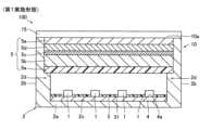
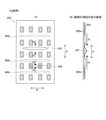
図1に示すように、液晶表示装置100は、表示部15と、バックライトユニット10とを備える。バックライトユニット10は、複数のLED(light emitting diode)1と、保持部材2と、複数の反射シート3と、を備える。なお、LED1は、特許請求の範囲の「光源」の一例である。As shown in FIG. 1, the liquid
バックライトユニット10は、LED1の光を出光面10aから出射させる。バックライトユニット10は、出光面10aから出射される光の強度分布を均一化する構造を有する。出光面10aは、保持部材2のうちLED1が設置された設置面2cとは反対側の表面である。表示部15が、複数の反射シート3と対向するように保持部材2の出光面10aに配置されている。The
表示部15は、複数の画素を含む液晶表示パネルにより構成される。表示部15は、偏光板と液晶セルとを含む。表示部15は、複数の画素の各々における光の透過率を変化させることにより、バックライトユニット10からの光を用いて映像(画像)を表示する。表示部15は、図示しない制御部からの制御信号に基づいて駆動される。The
次に、バックライトユニット10の構造について説明する。Next, the structure of the
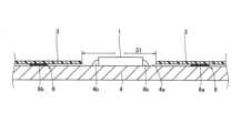
LED1は、出光面10aに向けて光を照射する。複数のLED1は、保持部材2の設置面2cにおいて、互いに間隔を隔てて分布するように設けられている。具体的には、複数のLED1は、設置面2cに取り付けられた基板4に実装されている。基板4は、複数のLED1を発光させるための回路パターン(図示せず)が形成された回路基板である。図2に示すように、LED1は、半田部4bによって基板4の表面4aに固定されるとともに、半田部4bを介して回路パターンに電気的に接続されている。LED1は、素子および蛍光体が封入されたパッケージにより構成される。LED1は白色光を出射する。複数のLED1は、たとえば、マトリクス状(図3参照)に配置されている。The
図1の例では、保持部材2は、上方が開口した直方体形状(箱状形状)を有する。開口部分には、光学シート部5が設けられている。光学シート部5に覆われた開口部分が出光面10aを構成する。保持部材2は、底面部2aと、底面部2aの周縁から立ち上がる側面部2bとを有する。複数のLED1が設置される設置面2cは、底面部2aの内側表面(つまり、保持部材2の内底面)である。側面部2bは、底面部2aの周縁を全周にわたって取り囲むように設けられている。In the example of FIG. 1, the holding
反射シート3は、保持部材2の設置面2cを覆うように設けられている。言い換えると、反射シート3は、設置面2cに設けられた基板4の表面4aを覆っている。第1実施形態では、複数の反射シート3(図3参照)が、保持部材2の設置面2cを分割して覆うように位置決めされている。各反射シート3は、保持部材2の設置面2c上において、複数のLED1の各々を露出させる複数の開口部31を有している。つまり、反射シート3は、複数の開口部31の各々により、複数のLED1およびその近傍領域を出光面10a側に露出させつつ、LED1以外の基板4の表面4aを覆うように設けられている。The
図1に示すように、反射シート3は、保持部材2の設置面2c上において、光学シート部5と間隔を隔てて対向するように設けられている。これにより、保持部材2の内部には、光学シート部5、反射シート3および側面部2bにより囲まれた空間が形成されている。反射シート3は、図4に示すように、空間内で光を出光面10a(光学シート部5)側へ反射させることにより、光の強度分布を均一化するとともに光の利用効率を向上させる機能を有する。反射シート3は、たとえば、微細発泡樹脂により形成されている。反射シート3は、たとえば、微細発泡ポリエチレンテレフタラートにより形成されている。なお、反射シート3の反射率は、基板4の表面4aの反射率、および、半田部4bの反射率よりも大きい。As shown in FIG. 1, the
また、図1に示すように、バックライトユニット10は、光学シート部5を含む。保持部材2は、側面部2bにおいて内周側へ突出する段差部2dが形成されている。光学シート部5は、この段差部2dによって外周部分が支持されている。As shown in FIG. 1, the
光学シート部5は、機能(光特性)の異なる複数の光学シートを含んで構成されている。たとえば、図1の例では、光学シート部5は、光均一化シート5aと、拡散板5bと、プリズムシート5cと、反射型偏光フィルム5dと、ルーバーシート5eとを含む。光均一化シート5aと、拡散板5bと、プリズムシート5cと、反射型偏光フィルム5dと、ルーバーシート5eとが、設置面2c側から出光面10a側へ向けて、この順で積層されている。The
光均一化シート5aは、LED1から照射される光を透過させる透過部と、LED1から照射される光を反射させる反射部とを含む。光均一化シート5aは、光の一部を透過させ、他の一部を反射させることにより、輝度を均一化する機能を有する。反射部は、光を反射するシート表面により構成されている。透過部は、たとえば光均一化シート5aに形成された貫通孔により構成されている。透過光の輝度分布が均一化されるように、透過部が光均一化シート5aの全体に多数形成されている。The
拡散板5bは、光均一化シート5aの透過部を透過した光を散乱させる。拡散板5bは、たとえば、ポリカーボネートなどの樹脂により形成されている。プリズムシート5cは、拡散板5bで散乱した光を一定方向に屈折させて出光面10a側に集光させる機能を有する。The
反射型偏光フィルム5dは、表示部15において吸収される偏光方向の光を反射し、吸収されない偏光方向の光を透過する。反射した光を反射シート3を介して再入射させることにより、光の利用効率を向上させることが可能である。ルーバーシート5eは、反射型偏光フィルム5dを透過した光のうち、ルーバーシート5eに対して斜めに入射する光を遮光する機能を有する。The reflective
なお、光学シート部5は、上記した複数の光学フィルムの一部のみを備えていてもよいし、上記した複数の光学フィルム以外の他の機能を有する光学フィルムを備えていてもよい。The
このような構成により、複数のLED1から出射された光の一部は、光学シート部5を透過して出光面10aから表示部15へ出力される。複数のLED1から出射された光の他の一部は、図4に示したように、光均一化シート5aや反射型偏光フィルム5dなどにより反射され、設置面2c側へ戻される。戻された光は、反射シート3により再度出光面10a側へ反射される。この結果、反射シート3と光学シート部5との間で光が多重反射することにより、出光面10aから出射される輝度分布が均一化される。With this configuration, a portion of the light emitted from the
(反射シートの構成)
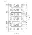
次に、反射シート3の構成について説明する。図3に示したように、バックライトユニット10(液晶表示装置100)は、保持部材2の設置面2cを分割して覆うように位置決めされた複数の反射シート3を備える。 (Configuration of Reflective Sheet)
Next, a description will be given of the configuration of the
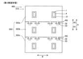
第1実施形態では、複数の反射シート3は、外周部に係合片部32を有する第1反射シート3aと、第1反射シート3aと隣り合うとともに、係合片部32と位置ずれ可能に係合する被係合部33を有する第2反射シート3bと、を含む。図3は、単純な構成の例として、複数の反射シート3が、1つの第1反射シート3aと1つの第2反射シート3bとによって構成される例を示す。1つの第1反射シート3aと1つの第2反射シート3bとによって設置面2cの略全体が覆われている。複数の反射シート3は、第1反射シート3aと第2反射シート3bとが係合するように組み合わされた反射シート組立体(サブアセンブリ)として構成されている。第1反射シート3aおよび第2反射シート3bは、いずれも、複数設けられていてもよい。1つの第1反射シート3a(または第2反射シート3b)が、複数の第2反射シート3b(または第1反射シート3a)と係合してもよい。In the first embodiment, the multiple
図5に示すように、第1反射シート3aおよび第2反射シート3bは、いずれも4つの辺を有する長方形状に形成されている。図5の例では、第1反射シート3aの方が第2反射シート3bよりも大きく形成されているが、第1反射シート3aおよび第2反射シート3bが同じ大きさでもよいし、第2反射シート3bの方が第1反射シート3aよりも大きくてもよい。As shown in FIG. 5, the
第1反射シート3aは、第2反射シート3b側の辺34において、係合片部32を有する。係合片部32は、第1反射シート3aの外周部から外向きに突出するように形成されている。係合片部32は、第1反射シート3aと一体形成されている。つまり、第1反射シート3aが係合片部32を含む形状に切り出されている。係合片部32の数は、1つまたは複数でありうる。図5の例では、係合片部32は、第1反射シート3aは、第2反射シート3b側の辺34に間隔を隔てて複数(2つ)形成されている。図5の例では、係合片部32は、矩形形状を有する。The first
第2反射シート3bは、第1反射シート3a側の辺35の近傍に、被係合部33を有する。被係合部33は、第2反射シート3bに形成され係合片部32が挿入されるスリットである。つまり、図5の例では、被係合部33は、第2反射シート3bを厚み方向に貫通する直線状の貫通孔である。被係合部33は、複数(2つ)の係合片部32と一対一で対応するように、係合片部32の数と同数(2つ)設けられている。図3に示したように、第1反射シート3aの係合片部32が、第2反射シート3bの被係合部33内に挿入されることにより、第1反射シート3aと第2反射シート3bとが係合している。第1反射シート3aおよび第2反射シート3bは、係合状態を維持したまま、係合片部32の挿入方向およびその反対方向(挿抜方向)に、位置ずれ可能に構成されている。The
被係合部33は、係合片部32と係合した状態で、第1反射シート3aの外周部が第2反射シート3bと重なるように、第2反射シート3bの外周部よりも内側の位置に配置されている。つまり、被係合部33は、第2反射シート3bの辺35から所定の間隔を隔てた位置に形成されている。この結果、第1反射シート3aの辺34と第2反射シート3bの辺35との間の領域RDにおいて、第1反射シート3aと第2反射シート3bとが重なり合っている。The engaged
なお、図3の例では、係合片部32が第2反射シート3bの上面側から被係合部33に挿入されており、第1反射シート3aが第2反射シート3bの上面に重なっている。逆に、係合片部32が第2反射シート3bの下面側から被係合部33に挿入され、第1反射シート3aが第2反射シート3bの下面に重なっていてもよい。In the example of FIG. 3, the engaging
第1反射シート3aおよび第2反射シート3bは、係合片部32が先端部32a(図5参照)と根元部(辺34に対する接続位置)との間の位置まで被係合部33に挿入された状態で、位置決めおよび固定されている。挿入長さは、根元部(辺34)から先端部32aまでの係合片部32の全長の半分程度でありうる。このため、第1反射シート3aおよび第2反射シート3bは、温度上昇に起因する膨張によって係合片部32と被係合部33とが互いに近付く方向(矢印Ex参照)へ位置ずれした場合にも、挿入量を増大させることで係合状態を維持したまま位置ずれを吸収できる。第1反射シート3aおよび第2反射シート3bは、温度低下に起因する収縮によって係合片部32と被係合部33とが互いに離れる方向へ位置ずれした場合にも、挿入量を減少させることで係合状態を維持したまま位置ずれを吸収できる。The
ここで、反射シート3は、シート表面内の第1方向Aにおいて熱膨張量が相対的に大きく、シート表面内の第1方向Aと直交する第2方向Bにおいて熱膨張量が相対的に小さい樹脂シートからなる。第1方向Aは、樹脂シートの製造時の機械流れ方向であり、いわゆるMD方向である。第2方向Bは、樹脂シートの面内でMD方向に直交する幅方向であり、いわゆるTD方向である。第1反射シート3aおよび第2反射シート3bが温度変化に晒された場合に生じる膨張収縮は、主として第1方向Aに沿って生じる。The
第1反射シート3aおよび第2反射シート3bは、各々の第1方向Aが、互いに隣り合う方向と一致するように設けられている。そのため、係合片部32は、第1反射シート3aの第1方向Aの外周部に形成され、第2反射シート3bの被係合部33は、係合片部32と第1方向Aへ位置ずれ可能に係合するように形成されている。係合片部32が形成された辺34は、第1方向Aにおける第1反射シート3aの端部であり、第2方向Bに沿って延びる辺である。同様に、第2反射シート3bの辺35は、第1方向Aにおける第2反射シート3bの端部であり、第2方向Bに沿って延びる辺である。The
(接着部材)
複数の反射シート3の各々は、接着部材6によって保持部材2の所定位置に固定されている。接着部材6(図2参照)は、複数の反射シート3の各々を、基板4の表面4aに接着するように設けられている。なお、基板4は、図示しない別の接着部材、または、ねじなどの締結部材により保持部材2の設置面2cに固定されている。 (Adhesive member)
Each of the multiple
図3に示すように、第1実施形態では、複数の反射シート3の少なくとも1つには、反射シート3を設置面2cに沿った方向へ移動不能に接着する第1接着部材6aと、第1接着部材6aと反射シート3の外周部との間に配置され、反射シート3を設置面2cに沿った方向へ位置ずれ可能に接着する第2接着部材6bと、が設けられている。図3および図5では、便宜的に、第1接着部材6aと第2接着部材6bとに異なるハッチングを付して図示している。As shown in FIG. 3, in the first embodiment, at least one of the multiple reflecting
図3の例では、第1反射シート3aおよび第2反射シート3bのうち、大きい方の第1反射シート3aに対して、第1接着部材6aと第2接着部材6bとが設けられている。小さい方の第2反射シート3bには、第1接着部材6aが設けられており第2接着部材6bが設けられていない。第2反射シート3bには、第2接着部材6bがさらに設けられていてもよい。In the example of FIG. 3, the first reflecting
第1接着部材6aは、1つの反射シート3(第1反射シート3a、第2反射シート3b)の面内において1箇所に設けられている。第1接着部材6aは、反射シート3(第1反射シート3a、第2反射シート3b)を移動不能に接着することにより、反射シート3(第1反射シート3a、第2反射シート3b)を保持部材2内の所定位置に位置決めするとともに、その位置を保持させるように構成されている。このため、反射シート3(第1反射シート3a、第2反射シート3b)に熱膨張または熱収縮が生じる場合、反射シート3の各部が第1接着部材6aから離れる方向に熱膨張し、第1接着部材6aに近付く方向に熱収縮する。図3の矢印Exは、反射シート3に発生する熱膨張の方向を示す。The first
第2接着部材6bは、第1接着部材6aよりも反射シート3(第1反射シート3a)の外周部側の複数箇所に設けられている。第2接着部材6bは、反射シート3(第1反射シート3a)を設置面2cに沿った方向へ位置ずれ可能に接着することにより、反射シート3(第1反射シート3a)に熱膨張または熱収縮が発生した場合に接着箇所の位置ずれを許容しつつ、反射シート3(第1反射シート3a)の外周部のめくれ上がり、浮き上がり、反りなどを防ぐように構成されている。The second
より具体的には、第1接着部材6aは、第1反射シート3aの第1方向Aにおける中央部側に設けられ、第2接着部材6bは、第1接着部材6aに対して第1方向Aに離れた位置に設けられている。第1接着部材6aおよび第2接着部材6bは、それぞれ、第2方向Bに沿って線状に延びるように設けられ、第1方向Aに沿って間隔を隔てて並ぶように配置されている。More specifically, the first
第1接着部材6aおよび第2接着部材6bが、膨張、収縮が生じにくい第2方向Bに沿って線状に延びるように設けられることにより、第1反射シート3aの膨張収縮方向が第1方向Aに略限定される。そして、第1接着部材6aおよび第2接着部材6bが、第1方向Aに沿って間隔を隔てて並ぶことにより、第1方向Aの中央部において第1反射シート3aの熱膨張(矢印Ex参照)が生じた場合、第2接着部材6bは、第1反射シート3aとの接着状態を維持したまま、第1方向Aの外側(矢印Ex方向)へ向かう反射シート3の位置ずれ(熱膨張)に追従する。The first
このように特性の異なる複数の接着部材6(第1接着部材6a、第2接着部材6b)は、粘着テープまたは接着剤の少なくとも一方により構成されうる。そして、第2接着部材6bは、第1接着部材6aよりも接着力が低いかまたは変形しやすい材料により構成されている。なお、粘着テープ(両面テープ)は、基材フィルムの表面に接着剤(粘着剤)を塗布したものである。接着剤は接着過程の少なくとも一部において液体であり、その後硬化することにより接着する。1つの例では、第2接着部材6bが接着剤により構成されており、硬化状態において第1接着部材6aよりも変形しやすい(柔軟である)。他の1つの例では、第2接着部材6bが粘着テープにより構成されており、第1接着部材6aよりも接着力が低い。第2接着部材6bには、特にせん断方向(設置面2cに沿った方向)に第1接着部材6aよりも変形しやすい粘着テープが選択される。第1接着部材6aには、略変形が生じない(硬い)粘着テープまたは接着剤が選択される。The multiple adhesive members 6 (first
(開口部の形状)
次に、開口部31の形状(大きさ)について説明する。図2に示したように、開口部31は、LED1の外形よりも大きく形成され、LED1を露出させる。開口部31の大きさは、反射シート3の組付位置のばらつき、LED1の実装位置のばらつき、基板4の取付位置のばらつき、および、反射シート3の膨張収縮による変位、などを考慮して、LED1が膨張収縮により変位する反射シート3に押圧されたり覆われたりしない大きさに設計される。開口部31内では、LED1以外に、半田部4bや基板4の表面4aなどが、反射シート3に覆われずに露出する。半田部4bや表面4aの光反射率は反射シート3の光反射率よりも低いため、開口部31は、上記のばらつきや膨張収縮を考慮した上でなるべく小さく形成することが望ましい。 (Shape of opening)
Next, the shape (size) of the
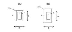
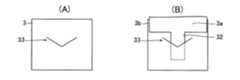
そこで、第1実施形態では、図5に示すように、反射シート3の複数の開口部31は、第1接着部材6aに対して第1方向Aに第1距離D1を隔てて配置された第1開口部31aと、第1接着部材6aに対して第1方向Aに第1距離D1よりも大きい第2距離D2を隔てて配置された第2開口部31bと、を含む。そして、第2開口部31bは、第1開口部31aよりも、第1方向Aの寸法が大きい。すなわち、図6(A)に示す第1開口部31aは、第1方向Aにおける長さL1を有する。図6(B)に示す第2開口部31bは、第1方向Aにおける長さL2を有する。長さL2は長さL1よりも大きい。In the first embodiment, as shown in FIG. 5, the
より具体的には、複数の開口部31は、第1接着部材6aからの第1方向Aの距離が大きいほど第1方向Aの開口寸法(内寸)が大きくなるように形成されている。言い換えると、複数の開口部31は、第1接着部材6aからの第1方向Aの距離が小さいほど第1方向Aの開口寸法(内寸)が小さくなるように形成されている。したがって、たとえば第1接着部材6aに対して第2距離D2を隔てて配置された第2開口部31bよりもさらに距離を隔てた位置に、第3の開口部が設けられる場合、第3の開口部の第1方向Aの開口寸法は、第2開口部31bの第1方向Aの開口寸法(長さL2)よりも大きくされる。反射シート3の膨張収縮量は、第1接着部材6aからの第1方向Aの距離に応じて増大するため、各開口部31の大きさが、反射シート3の膨張収縮量に応じて必要最小限となるように設定されている。More specifically, the
(第1実施形態の効果)
第1実施形態では、以下のような効果を得ることができる。 (Effects of the First Embodiment)
In the first embodiment, the following effects can be obtained.
第1実施形態によるバックライトユニット10および液晶表示装置100では、上記のように、複数のLED1の各々を露出させる複数の開口部31を有し、保持部材2の設置面2cを分割して覆うように位置決めされた複数の反射シート3を備え、複数の反射シート3は、外周部に係合片部32を有する第1反射シート3aと、第1反射シート3aと隣り合うとともに、係合片部32と位置ずれ可能に係合する被係合部33を有する第2反射シート3bと、を含む。これにより、反射シート3が複数に分割されるとともに、隣り合う第1反射シート3aと第2反射シート3bとを、係合片部32と被係合部33とにより互いに位置ずれ可能な状態で係合させることができる。この結果、第1反射シート3aおよび第2反射シート3bに熱膨張が発生した場合でも、係合片部32と被係合部33とが位置ずれすることによって膨張量を吸収できるので、温度変化に伴う反射シート3の熱膨張に起因して反射シート3に皺が発生するのを抑制することができる。すなわち、第1反射シート3aと第2反射シート3bが互いの境界部分(領域RD)に向けて熱膨張した場合でも、領域RDにおいて係合片部32と被係合部33とが膨張分だけ位置ずれできるので、シートに皺(波打ち)が発生することを抑制できる。In the
さらに上記構成によれば、係合片部32と被係合部33とが係合したまま位置ずれできるので、第1反射シート3aと第2反射シート3bとの境界部分(領域RD)を接着しなくても、反射シート3の縁部(辺34、辺35)がめくれ上がることも抑制できる。また、第1反射シート3aと第2反射シート3bとを係合させた状態で保持部材2に取り付けることができる。つまり、取付前に、事前に第1反射シート3aと第2反射シート3bとを係合させた反射シート組立体を構成しておき、この反射シート組立体を保持部材2に取り付けることができる。このため、複数の反射シート3を、あたかも単一(1枚)の反射シートのように取り扱うことができるので、複数の反射シート3を1枚ずつ取り付ける場合と比較して、組立作業性を向上させることができる。Furthermore, according to the above configuration, since the engaging
また、第1実施形態では、上記のように、係合片部32は、第1反射シート3aの外周部から外向きに突出するように形成され、被係合部33は、第2反射シート3bに形成され係合片部32が挿入されるスリットである。これにより、係合片部32をスリット(被係合部33)に挿入するだけの簡単な構成で、第1反射シート3aと第2反射シート3bとを位置ずれ可能に係合させることができる。これにより、反射シート3の熱膨張を吸収できる構成でありながら、高い組立作業性を実現できる。また、係合片部32および被係合部33の形状が簡素で凹凸が少なくできるため、反射シート3に係合片部32および被係合部33を形成しても、反射シート3による反射光の強度分布にムラが生じることを抑制できる。In the first embodiment, as described above, the engaging
また、第1実施形態では、上記のように、被係合部33は、係合片部32と係合した状態で、第1反射シート3aの外周部が第2反射シート3bと重なるように、第2反射シート3bの外周部よりも内側の位置に配置されている。これにより、第1反射シート3aと第2反射シート3bとの境界部分で、いずれの反射シート3にも覆われない領域が形成されることを防止できる。これにより、反射シート3による反射光の強度分布にムラが生じることを抑制できる。In addition, in the first embodiment, as described above, the engaged
また、第1実施形態では、上記のように、反射シート3は、シート表面内の第1方向Aにおいて熱膨張量が相対的に大きく、シート表面内の第1方向Aと直交する第2方向Bにおいて熱膨張量が相対的に小さい樹脂シートからなり、係合片部32は、第1反射シート3aの第1方向Aの外周部に形成され、第2反射シート3bの被係合部33は、係合片部32と第1方向Aへ位置ずれ可能に係合するように形成されている。これにより、第1反射シート3aおよび第2反射シート3bの係合状態を維持した位置ずれによって、特に熱膨張量が大きい第1方向Aにおける膨張量を吸収できるので、熱膨張に起因して反射シート3に皺が発生するのを、より効果的に抑制することができる。In the first embodiment, as described above, the
また、第1実施形態によるバックライトユニット10および液晶表示装置100では、上記のように、保持部材2の所定位置に反射シート3を固定するための複数の接着部材6を備え、複数の接着部材6は、反射シート3を設置面2cに沿った方向へ移動不能に接着する第1接着部材6aと、第1接着部材6aと反射シート3の外周部との間に配置され、反射シート3を設置面2cに沿った方向へ位置ずれ可能に接着する第2接着部材6bと、を含む。これにより、第1接着部材6aにより反射シート3の面内位置決めおよび固定を行う一方、第1接着部材6aの周囲では、第2接着部材6bによって反射シート3を面内方向に位置ずれ可能な状態で接着できる。この結果、反射シート3に熱膨張が発生した場合には、第1接着部材6aによる固定位置を中心として、外周部へ向けて反射シート3が伸びる(膨張する)ことになるものの、外周部側では、第2接着部材6bによって膨張による位置ずれを許容できるので、第1接着部材6aと第2接着部材6bとの間の領域で、反射シート3に皺が発生するのを抑制することができる。したがって、温度変化に伴う反射シート3の熱膨張に起因して反射シート3に皺が発生するのを抑制することができる。As described above, the
具体的には、図7(A)に示す比較例のように、1枚の反射シート903を、複数の同種の接着部材906a、906b、906cにより固定した場合、反射シート903には各接着部材906a、906b、906cから離れる方向(矢印Ex参照)に熱膨張が発生する。このため、隣り合う接着部材906aと接着部材906bとの間の領域907、隣り合う接着部材906bと接着部材906cとの間の領域908、に向けて、反射シート903が両側から押し合うように膨張し、領域907(図7(B)参照)および領域908で反射シート903に皺(波打ち)が形成される。図示は省略するが、領域908においせ発生する皺も図7(B)と同様である。Specifically, as in the comparative example shown in FIG. 7A, when one
これに対して、上記第1実施形態(図3参照)では、第1接着部材6aの外周側に、反射シート3が位置ずれ可能な第2接着部材6bが設けられるので、第1接着部材6aから離れる方向(矢印Ex参照)に発生した熱膨張を位置ずれにより吸収できる。その結果、第1接着部材6aと第2接着部材6bとの間の領域RB(図3参照)で反射シート3に皺(波打ち)が形成されることを抑制できる。さらに、第1実施形態によれば、第2接着部材6bが反射シート3の膨張収縮に起因する位置ずれを許容しつつ接着状態を維持するので、反射シート3の縁部がめくれ上がることも抑制できる。In contrast, in the first embodiment (see FIG. 3), the second
また、上記第1実施形態では、図3に示したように、複数の反射シート3の少なくとも1つ(第1反射シート3a)に、第1接着部材6aと第2接着部材6bと、が設けられているので、分割により各反射シート3の境界部分(領域RD)で熱膨張に起因する皺が発生するのを抑制するだけでなく、第1反射シート3aにおいて複数の接着箇所の間の部分(領域RB)で皺が発生することも抑制できる。In addition, in the first embodiment, as shown in FIG. 3, at least one of the multiple reflecting sheets 3 (first reflecting
また、第1実施形態では、上記のように、第1接着部材6aは、反射シート3の面内において1箇所に設けられ、第2接着部材6bは、第1接着部材6aよりも反射シート3の外周部側の位置に複数設けられている。これにより、反射シート3に熱膨張が発生した時、第1接着部材6aが設けられた1箇所の固定箇所を中心として、外周側に向けて反射シート3が伸びる。この反射シート3の伸びを、第2接着部材6b側で吸収しつつ、複数の第2接着部材6bによって反射シート3のめくれ上がりや浮き、反りなどを効果的に抑制できる。その結果、反射シート3による反射光の強度分布にムラが生じることを効果的に抑制できる。In the first embodiment, as described above, the first
また、第1実施形態では、上記のように、反射シート3は、シート表面内の第1方向Aにおいて熱膨張量が相対的に大きく、シート表面内の第1方向Aと直交する第2方向Bにおいて熱膨張量が相対的に小さい樹脂シートからなり、第1接着部材6aは、反射シート3の第1方向Aにおける中央部側に設けられ、第2接着部材6bは、第1接着部材6aに対して第1方向Aに離れた位置に設けられている。これにより、熱膨張が発生すると、反射シート3は、第1接着部材6aによる固定位置から第1方向Aへ離れる方向に相対的に大きく位置ずれ(膨張)するが、この第1方向Aにおける膨張量を第2接着部材6bにより吸収できるので、熱膨張に起因して反射シート3に皺が発生するのを、より効果的に抑制することができる。In the first embodiment, as described above, the reflecting
また、第1実施形態では、上記のように、第1接着部材6aおよび第2接着部材6bは、それぞれ、第2方向Bに沿って線状に延びるように設けられ、第1方向Aに沿って間隔を隔てて並ぶように配置されている。これにより、第1接着部材6aおよび第2接着部材6bが、熱膨張量が小さい第2方向Bに線状に伸びることにより、大きな接着面積を容易に確保できるとともに、反射シート3の熱膨張による位置ずれの方向を、実質的に第1方向Aに限定することができる。そして、この第1方向Aの位置ずれを、第2接着部材6bにより効果的に吸収できる。In the first embodiment, as described above, the first
また、第1実施形態では、上記のように、反射シート3の複数の開口部31は、第1接着部材6aに対して第1方向Aに第1距離D1を隔てて配置された第1開口部31aと、第1接着部材6aに対して第1方向Aに第1距離D1よりも大きい第2距離D2を隔てて配置された第2開口部31bと、を含み、第2開口部31bは、第1開口部31aよりも、第1方向Aの寸法が大きい。これにより、反射シート3を固定する第1接着部材6aから第1方向Aに離れるに従って反射シート3の熱膨張による開口部31の位置ずれが大きくなるので、第1方向Aの寸法が大きい第2開口部31bによって、位置ずれが生じた場合でも反射シート3とLED1とが接触することを回避できる。そして、第1接着部材6aとの距離が小さい第1開口部31aの方は、熱膨張に起因する位置ずれも小さくなるため、第2開口部31bと比較して第1方向Aの寸法を小さくし、第1開口部31aの縁部とLED1との間の反射シート3に覆われない領域を極力小さくできる。その結果、反射シート3による反射光の強度分布にムラが生じることを抑制できる。In the first embodiment, as described above, the
また、第1実施形態では、上記のように、複数の接着部材6は、粘着テープまたは接着剤の少なくとも一方を含み、第2接着部材6bは、第1接着部材6aよりも接着力が低いかまたは変形しやすい材料により構成されている。これにより、第1接着部材6aによって反射シート3を固定しつつ、第1接着部材6aよりも接着力が低いかまたは変形しやすい接着部材6を第2接着部材6bとして用いることによって、位置ずれを許容しつつ反射シート3のめくれ上がりや浮きを防止可能な構成を容易に実現できる。In the first embodiment, as described above, the multiple
[第2実施形態]
次に、図8および図9を参照して、第2実施形態によるバックライトユニット210および液晶表示装置200の構成について説明する。第2実施形態では、反射シート3に対して第1接着部材6aおよび第2接着部材6bを設けた第1実施形態とは異なり、各反射シート103に第1接着部材6aおよび第2接着部材6bを設けない例を示す。なお、バックライトユニット110および液晶表示装置200は、それぞれ、特許請求の範囲の「面光源装置」および「表示装置」の一例である。第2実施形態において、反射シート103以外の構成は、上記第1実施形態と同様であるので、上記第1実施形態と同一の符号を用いるとともに説明を省略する。 [Second embodiment]
Next, the configuration of a
図8および図9に示すように、液晶表示装置200(バックライトユニット110)は、第1反射シート103aと第2反射シート103bとを含む複数の反射シート103を備える。なお、図8の例では、第1反射シート103aが4つの係合片部32を有し、第2反射シート103bが4つの被係合部33を有する例を示している。また、図8では、模式的に、4つのLED1のみを示しているが、LED1の数はこれに限定されない。As shown in Figs. 8 and 9, the liquid crystal display device 200 (backlight unit 110) includes a plurality of
複数の反射シート103の各々は、保持部材2の所定位置に固定されている。第2実施形態では、複数の反射シート103の各々は、接着部材6によって固定されていてもよいし、接着部材6以外の固定手段によって固定されてもよい。接着部材6以外の固定手段としては、たとえば、ねじなどの締結部材、リベットなどのかしめ部材などを用いてもよい。熱膨張が生じた場合、複数の反射シート103の各々は、固定位置から離れる方向に膨張する。図8および図9では、固定手段の図示を省略している。Each of the multiple
各反射シート103に熱膨張が生じた場合でも、係合片部32と被係合部33との係合状態を維持したまま、第1反射シート103aの辺34は第2反射シート103b側へ位置ずれ可能であり、第2反射シート103bの辺35は第1反射シート103a側へ位置ずれ可能である。そのため、第1反射シート103aと第2反射シート103bとの境界部分(領域RD)において、シートの皺の発生が抑制される。Even if thermal expansion occurs in each
また、第2実施形態では、各反射シート103に第2接着部材6bが設けられていないものの、各反射シート103の外周部では、係合片部32と被係合部33とが係合し合う。このため、各反射シート103の外周部のめくれ上がり、浮き、反りなどが抑制される。In addition, in the second embodiment, although the second
第2実施形態のその他の構成は、上記第1実施形態と同様である。The rest of the configuration of the second embodiment is the same as that of the first embodiment.
(第2実施形態の効果)
第2実施形態では、上記のように、複数の反射シート103が、第1反射シート103aと、第2反射シート103bと、を含むことにより、上記第1実施形態と同様に、温度変化に伴う反射シート103の熱膨張に起因して反射シート103に皺が発生するのを抑制することができる。さらに上記構成によれば、第1反射シート103aと第2反射シート103bとの境界部分(領域RD)を接着しなくても、反射シート103の縁部(辺34、辺35)がめくれ上がることも抑制できる。また、複数の反射シート103を、あたかも単一(1枚)の反射シートのように取り扱うことができるので、複数の反射シートを1枚ずつ取り付ける場合と比較して、組立作業性を向上させることができる。 (Effects of the Second Embodiment)
In the second embodiment, as described above, the multiple
第2実施形態のその他の効果は、第1実施形態と同様である。The other effects of the second embodiment are the same as those of the first embodiment.
[第3実施形態]
次に、図10を参照して、第3実施形態によるバックライトユニット210および液晶表示装置300の構成について説明する。第3実施形態では、複数の反射シート3を設けた第1実施形態とは異なり、単一の反射シート203に、第1接着部材6aおよび第2接着部材6bを設けた例を示す。なお、バックライトユニット210および液晶表示装置300は、それぞれ、特許請求の範囲の「面光源装置」および「表示装置」の一例である。第3実施形態において、反射シート203以外の構成は、上記第1実施形態と同様であるので、上記第1実施形態と同一の符号を用いるとともに説明を省略する。 [Third embodiment]
Next, the configuration of a
図10に示すように、液晶表示装置300(バックライトユニット210)は、上記第1実施形態と異なり、単一の反射シート203を備えている。反射シート203は、複数のLED1の各々を露出させる複数の開口部31を有し、保持部材2の設置面2cを覆うように配置されている。反射シート203は、単一部材として構成されているので、上記第1実施形態と異なり係合片部32および被係合部33は設けられていない。液晶表示装置300(バックライトユニット210)は、保持部材2(図1参照)の所定位置に反射シート203を固定するための複数の接着部材6を備えている。As shown in FIG. 10, the liquid crystal display device 300 (backlight unit 210) is provided with a single
複数の接着部材6は、反射シート203を設置面2c(図1参照)に沿った方向へ移動不能に接着する第1接着部材6aと、第1接着部材6aと反射シート203の外周部との間に配置され、反射シート203を設置面2cに沿った方向へ位置ずれ可能に接着する第2接着部材6bと、を含む。第1接着部材6aおよび第2接着部材6bは、上記第1実施形態と同様の粘着テープまたは接着剤により構成されている。The multiple
第1接着部材6aは、反射シート203の面内において1箇所に設けられ、第2接着部材6bは、第1接着部材6aよりも反射シート203の外周部側の複数箇所に設けられている。第1接着部材6aは、反射シート203の第1方向Aにおける中央部側に設けられ、第2接着部材6bは、第1接着部材6aに対して第1方向Aに離れた位置に設けられている。The first
図10では、1つの第1接着部材6aに対して、第1方向Aの両側となる位置に、1つずつ第2接着部材6bが設けられている。第1接着部材6aおよび第2接着部材6bは、それぞれ、第2方向Bに沿って線状に延びるように設けられ、第1方向Aに沿って間隔を隔てて並ぶように配置されている。In FIG. 10, one
これにより、反射シート203は、主として第1方向Aに沿って熱膨張を生じる。熱膨張は、第1接着部材6aの固定位置から、離れる方向(矢印Ex参照)に向けて生じる。As a result, the
反射シート203に熱膨張が生じた場合でも、反射シート203の第2接着部材6bによる接着箇所は、そのまま第1接着部材6aから離れる方向へ向けて位置ずれする。そのため、第1接着部材6aと第2接着部材6bとの間の領域RBにおいて、シートの皺の発生が抑制される。Even if thermal expansion occurs in the
反射シート203の外周縁部には、さらに第2接着部材6bを設けてもよい。これにより、シートの皺の発生を抑制しつつ、各反射シート203の外周部のめくれ上がり、浮き、反りなどを効果的に抑制できる。A second
第3実施形態のその他の構成は、上記第1実施形態と同様である。The rest of the configuration of the third embodiment is the same as that of the first embodiment.
(第3実施形態の効果)
第3実施形態では、上記のように、複数の接着部材6が、反射シート203を設置面2cに沿った方向へ移動不能に接着する第1接着部材6aと、第1接着部材6aと反射シート203の外周部との間に配置され、反射シート203を設置面2cに沿った方向へ位置ずれ可能に接着する第2接着部材6bと、を含む。これにより、上記第1実施形態と同様に、第2接着部材6bによって膨張による位置ずれを許容できるので、第1接着部材6aと第2接着部材6bとの間の領域RBで、反射シート203に皺が発生するのを抑制することができる。したがって、温度変化に伴う反射シート203の熱膨張に起因して反射シート203に皺が発生するのを抑制することができる。 (Effects of the Third Embodiment)
In the third embodiment, as described above, the multiple
第3実施形態のその他の効果は、第1実施形態と同様である。The other effects of the third embodiment are the same as those of the first embodiment.
[第4実施形態]
次に、図11および図12を参照して、第4実施形態によるバックライトユニット310および液晶表示装置400の構成について説明する。第4実施形態では、2つの反射シート3を設けた第1実施形態とは異なり、3つの反射シート303を設けた例を示す。なお、バックライトユニット310および液晶表示装置400は、それぞれ、特許請求の範囲の「面光源装置」および「表示装置」の一例である。第4実施形態において、反射シート303以外の構成は、上記第1実施形態と同様であるので、上記第1実施形態と同一の符号を用いるとともに説明を省略する。 [Fourth embodiment]
Next, the configuration of a
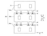
図11および図12に示すように、液晶表示装置400(バックライトユニット310)は、上記第1実施形態と異なり、複数の反射シート303は、第1反射シート303aおよび第2反射シート303bに加えて、第3反射シート303cをさらに含む。図12の例では、第1反射シート303a、第2反射シート303bおよび第3反射シート303cが1つずつ設けられ、合計3つの反射シートが設けられる例を示している。As shown in Figs. 11 and 12, the liquid crystal display device 400 (backlight unit 310) is different from the first embodiment in that the multiple
第1反射シート303aは、第1実施形態の第1反射シート3aと同様の係合片部32を有する。第2反射シート303bは、第1実施形態の第2反射シート3bと異なり、シート表面内の第1反射シート303a側に被係合部33を有するとともに、シート表面内の第3反射シート303c側に係合片部32を有する。第3反射シート303cは、設置面2cに沿う方向において、第1反射シート303aとは反対側の位置で第2反射シート303bに隣り合うように設けられている。第3反射シート303cは、シート表面内の第2反射シート303b側に、第2反射シート303bの係合片部32と係合する被係合部33を有する。The
より一般化して説明すると、第4実施形態では、3つ以上の反射シート303が、所定の方向(A方向)に沿って並んで配置されている。所定の方向の一方側をA1方向、所定の方向の他方側をA2方向とする。各反射シート303のうち、A1方向側端部の反射シート(第3反射シート303c)を除いた各反射シート(第1反射シート303aおよび第2反射シート303b)に、それぞれA1方向へ向けて係合片部32が設けられている。各反射シート303のうち、A2方向側端部の反射シート(第1反射シート303a)を除いた各反射シート(第2反射シート303bおよび第3反射シート303c)に対して、それぞれA2方向側の外周部付近に被係合部33が設けられている。In a more generalized manner, in the fourth embodiment, three or more
これにより、図12に示すように、保持部材2への組付前に、複数の反射シート303を互いに係合させて反射シート組立体を構成する際に、全ての反射シート303を同じ方向に向けて係合させることができる。つまり、第2反射シート303bの被係合部33に対して、第1反射シート303aの係合片部32を所定の方向の一方側(A1方向側)に向けて挿入する。続いて、第3反射シート303cの被係合部33に対して、第2反射シート303bの係合片部32を所定の方向の一方側(A1方向側)に向けて挿入する。このため、組付時に、係合片部32の挿入方向が常に一定(A1方向)となる。As a result, as shown in FIG. 12, when the multiple
反射シート303が4つ以上に分割される場合でも同様である。その場合、中間に配置された第2反射シート303b(係合片部32および被係合部33の両方が設けられた反射シート303)の数を増やせばよい。The same applies when the
第4実施形態のその他の構成は、上記第1実施形態と同様である。The rest of the configuration of the fourth embodiment is the same as that of the first embodiment.
(第4実施形態の効果)
第4実施形態では、上記のように、複数の反射シート303が、第1反射シート303aと、第2反射シート303bと、を含むことにより、上記第1実施形態と同様に、温度変化に伴う反射シート303の熱膨張に起因して反射シート303に皺が発生するのを抑制することができる。さらに上記構成によれば、第1反射シート303aと第2反射シート303bとの境界部分(領域RD)を接着しなくても、反射シート303の縁部(辺34、辺35)がめくれ上がることも抑制できる。また、複数の反射シート303を、あたかも単一(1枚)の反射シートのように取り扱うことができるので、複数の反射シートを1枚ずつ取り付ける場合と比較して、組立作業性を向上させることができる。 (Effects of the Fourth Embodiment)
In the fourth embodiment, as described above, the plurality of
また、第4実施形態では、上記のように、複数の反射シート303は、設置面2cに沿う方向において、第1反射シート303aとは反対側の位置で第2反射シート303bに隣り合う第3反射シート303cをさらに含み、第2反射シート303bは、シート表面内の第1反射シート303a側に被係合部33を有するとともに、シート表面内の第3反射シート303c側に係合片部32を有し、第3反射シート303cは、シート表面内の第2反射シート303b側に、第2反射シート303bの係合片部32と係合する被係合部33を有する。これにより、第2反射シート303bに対して第1反射シート303aを係合させる方向(係合片部32を被係合部33に係合させる方向)と、第3反射シート303cに対して第2反射シート303bを係合させる方向とを、揃えることができる。このため、各反射シート303を端部側から順番に、同じ方向に係合させていくだけで組付作業を行える。反射シート303が4枚以上となる場合も、第2反射シート303bの数を増やせばよい。したがって、保持部材2の設置面2c(図1参照)を3枚以上の反射シート303により分割して覆う場合に、各反射シート303の組付作業性を効果的に向上させることができる。In the fourth embodiment, as described above, the multiple
第4実施形態のその他の効果は、第1実施形態と同様である。The other effects of the fourth embodiment are the same as those of the first embodiment.
[変形例]
なお、今回開示された実施形態は、すべての点で例示であって制限的なものではないと考えられるべきである。本発明の範囲は、上記した実施形態の説明ではなく特許請求の範囲によって示され、さらに特許請求の範囲と均等の意味および範囲内でのすべての変更(変形例)が含まれる。 [Modification]
It should be noted that the embodiments disclosed herein are illustrative and not restrictive in all respects. The scope of the present invention is indicated by the claims, not by the description of the embodiments above, and further includes all modifications (variations) within the meaning and scope of the claims.
たとえば、上記第1、第2および第4実施形態では、係合片部32が矩形状を有し、被係合部33が直線状のスリットである例を示したが、本発明はこれに限られない。本発明では、係合片部32が矩形以外の形状を有していてもよい。被係合部33が直線以外の形状のスリットであってもよい。For example, in the above first, second and fourth embodiments, the engaging
図13(A)~(F)には、係合片部32のバリエーションを示している。図13(A)は、上記第1、第2および第4実施形態で例示した係合片部32である。図13(B)では、係合片部32の先端部32aが先細り形状を有している。これにより、被係合部33への挿入を容易にできる。係合片部32は、図13(C)~(F)に示すような形状としてもよい。すなわち、係合片部32は、第1反射シート3aの外周部から突出するとともに先端部32aが先細り形状に形成された突出部32bと、突出部32bに対して側方に突出する抜け止め部32cと、を含む。図13(C)は、突出部32bおよび抜け止め部32cにより三角形状(矢印形状)に形成された係合片部32を示す。図13(D)は、先端部32aが台形状に形成された係合片部32を示す。図13(F)は、図13(C)の係合片部32に対して抜け止め部32cを根元部側へ変形させた矢印形状の係合片部32を示す。図13(F)は、先端部32aが半円形状に形成された係合片部32を示す。Figures 13(A) to (F) show variations of the
このように、図13(C)~(F)に示す例では、先細り形状の突出部32bによって、係合片部32を被係合部33に挿入し易くできる。このため、複数の反射シート3を設ける場合でも組付作業性を効果的に向上させることができる。さらに、係合片部32を被係合部33に挿入した後は、側方に突出する抜け止め部32cによって係合片部32を被係合部33から抜けにくくすることができるので、組付作業性をさらに効果的に向上させることができる。In this way, in the example shown in Figures 13(C) to (F), the tapered
また、図14~図16は、被係合部33のバリエーションを示している。図14(A)、図14(B)では、被係合部33が、V字状のスリットにより構成されている。V字形状により、係合片部32を被係合部33に挿入しやすくすることができる。図15(A)、図15(B)では、被係合部33が、矩形の3辺を構成するスリット(逆U字状のスリット)により構成されている。これにより、被係合部33が、反射シート3の厚み方向へ変位可能なフラップ部33aを有する。係合片部32の挿入時にフラップ部33aがスリットを拡げるように変位できるので、係合片部32を被係合部33に挿入しやすくすることができる。FIGS. 14 to 16 also show variations of the engaged
また、図16(A)の例では、被係合部33が、係合片部32の挿入方向に並んだ2つのスリットにより構成されている。したがって、図16(B)および図16(C)のように、被係合部33は、1つ目のスリットから係合片部32が差し込まれ、2つ目のスリットから係合片部32の先端部32aが抜け出るように係合する。図16(B)は、係合片部32が第2反射シート3bの表面側から1つめのスリットに差し込まれ、先端部32aが裏面側から2つ目のスリットを通過して表面側へ抜け出る例を示す。図16(C)は、係合片部32が第2反射シート3bの裏面側から1つめのスリットに差し込まれ、先端部32aが表面側から2つ目のスリットを通過して裏面側へ抜け出る例を示す。被係合部33は、このように構成されていてもよい。In the example of FIG. 16(A), the engaged
この他、被係合部33は、たとえば第2反射シート3bとは別体で設けられ、第2反射シート3bに固定された部材でもよい。たとえば被係合部33は、第2反射シート3bの表面に固定された環状のシート部材であって、環状部分の内部に係合片部32が挿入可能であってもよい。In addition, the engaged
また、上記第1、第2および第4実施形態では、係合片部32と被係合部33とが係合した状態で、第1反射シート3aの外周部と第2反射シート3bの外周部とが重なる領域RD(図3参照)が形成される例を示したが、本発明はこれに限られない。たとえば第1反射シート3aの辺34と第2反射シート3bの辺35とが離れていてもよい。ただし、反射シート3による反射光の強度分布を均一化する観点では、隙間が形成されないように、第1反射シート3aと第2反射シート3bとが重なる領域RDを形成することが好ましい。In the first, second and fourth embodiments, an example was shown in which a region RD (see FIG. 3) is formed in which the outer periphery of the first
また、上記第1~第4実施形態では、反射シート3(103、203、303)が、第1方向A(いわゆるMD方向)において熱膨張量が相対的に大きく、第2方向B(いわゆるTD方向)において熱膨張量が相対的に小さい樹脂シートからなる例を示したが、本発明はこれに限られない。本発明では、反射シートに、熱膨張量が方向に依存して変化しない樹脂シートを用いてもよい。また、反射シートに、金属材料など樹脂シート以外のシート部材を用いてもよい。In the above first to fourth embodiments, the reflective sheet 3 (103, 203, 303) is made of a resin sheet that has a relatively large amount of thermal expansion in the first direction A (so-called MD direction) and a relatively small amount of thermal expansion in the second direction B (so-called TD direction), but the present invention is not limited to this. In the present invention, the reflective sheet may be made of a resin sheet whose amount of thermal expansion does not change depending on the direction. Also, the reflective sheet may be made of a sheet material other than a resin sheet, such as a metal material.
また、上記第1、第2および第4実施形態では、係合片部32と被係合部33とが第1方向Aへ位置ずれ可能に係合する例を示したが、本発明はこれに限られない。係合片部32と被係合部33とが第2方向Bへ位置ずれ可能に係合してもよいし、第1方向Aおよび第2方向Bとは異なる方向へ位置ずれ可能に係合してもよい。In addition, in the first, second and fourth embodiments, the engaging
なお、上記第1、第2および第4実施形態では、第1反射シート3aと第2反射シート3bとが特定の方向(第1方向A)に沿って並ぶ例を示しているが、たとえば第1反射シート3aと第2反射シート3bとが縦横に(第1方向Aおよび第2方向Bに)並んで設けられていてもよい。In the above first, second and fourth embodiments, an example is shown in which the
また、上記第1および第3実施形態では、第1接着部材6aが、反射シート3の面内において1箇所に設けられる例を示したが、本発明はこれに限られない。たとえば反射シート3の面内のごく近い位置に、複数の第1接着部材6aが並んで設けられていてもよい。この場合、隣り合う第1接着部材6a同士の間における熱膨張は吸収できないが、複数の第1接着部材6aの間の距離が十分小さい場合、反射シート3に皺が発生することはない。In addition, in the above first and third embodiments, an example was shown in which the first
また、上記第1および第3実施形態では、第2接着部材6bが、第1接着部材6aよりも反射シート3の外周部側の複数箇所に設けられている例を示したが、本発明はこれに限られない。本発明では、第2接着部材6bが1箇所だけ設けられていてもよい。In addition, in the above first and third embodiments, the second
また、上記第1および第3実施形態では、第2接着部材6bが、第1接着部材6aに対して第1方向Aに離れた位置に設けられる例を示したが、本発明はこれに限られない。本発明では、第2接着部材6bが、第1接着部材6aに対して第2方向Bに離れた位置に設けられていてもよい。In the above first and third embodiments, the second
また、上記第1および第3実施形態では、第1接着部材6aおよび第2接着部材6bが、それぞれ、第2方向Bに沿って線状に延びるように設けられる例を示したが、本発明はこれに限られない。第1接着部材6aおよび第2接着部材6bの一方、または両方が、第2方向B以外の方向に延びるように設けられていてもよいし、線状以外の形状で設けられていてもよい。また、接着部材が線状に設けられる場合、一端から他端まで連続している必要はなく、たとえば、複数の点状の接着部材が線状に並んでいてもよい。In the above first and third embodiments, the first
また、上記第1および第3実施形態では、第1接着部材6aに対して近い位置に配置された第1開口部31aよりも、第1接着部材6aから遠い位置に配置された第2開口部31bの方が、第1方向Aの寸法が大きく形成された例を示したが、本発明はこれに限られない。本発明では、全ての開口部31が、同じ大きさに形成されていてもよい。In the above first and third embodiments, the
また、上記第1~第4実施形態では、本発明の表示装置として、液晶表示装置の例を示したが、本発明はこれに限らない。本発明の表示装置は、液晶表示装置以外の液晶テレビジョン装置に適用してもよい。また、本発明の表示装置は、たとえば車両などの移動体に搭載される表示装置に適用されてもよい。移動体に搭載される表示装置としては、たとえば自動車等の車両のメーターパネルに適用されうる。この場合、表示装置の外形形状(表示部の形状)は、メーターパネルの形状に適合するように設計される。そのため、本発明の表示装置および面光源装置は、表示面が矩形の直方体形状である必要はなく、たとえば表示面(出光面)が円形状、長円(オーバル)形状、矩形以外の多角形状などの任意の形状でありうる。In the above first to fourth embodiments, a liquid crystal display device is shown as an example of the display device of the present invention, but the present invention is not limited to this. The display device of the present invention may be applied to a liquid crystal television device other than a liquid crystal display device. The display device of the present invention may be applied to a display device mounted on a moving object such as a vehicle. As a display device mounted on a moving object, it may be applied to a meter panel of a vehicle such as an automobile. In this case, the outer shape of the display device (the shape of the display unit) is designed to match the shape of the meter panel. Therefore, the display surface of the display device and surface light source device of the present invention does not need to be a rectangular parallelepiped shape, and the display surface (light-emitting surface) may be any shape, such as a circle, an oval, or a polygonal shape other than a rectangle.
1 LED(光源)
2 保持部材
2c 設置面
3、103、203、303 反射シート
3a、103a、303a 第1反射シート
3b、103b、303b 第2反射シート
6 接着部材
6a 第1接着部材
6b 第2接着部材
10、110、210、310 バックライトユニット(面光源装置)
10a 出光面
15 表示部
31 開口部
31a 第1開口部
31b 第2開口部
32 係合片部
32a 先端部
32b 突出部
32c 抜け止め部
33 被係合部
100、200、300、400 液晶表示装置(表示装置)
303c 第3反射シート
A 第1方向
B 第2方向
D1 第1距離
D2 第2距離 1 LED (light source)
2 Holding
10a
303c Third reflection sheet A First direction B Second direction D1 First distance D2 Second distance
Claims (15)
Translated fromJapanese前記複数の光源が設置される設置面を有する保持部材と、
前記複数の光源の各々を露出させる複数の開口部を有し、前記保持部材の前記設置面を分割して覆うように位置決めされた複数の反射シートと、を備え、
前記複数の反射シートは、外周部に係合片部を有する第1反射シートと、前記第1反射シートと隣り合うとともに、前記係合片部が挿入されるスリットを有し、前記スリットに前記係合片部が挿入されることにより前記係合片部と位置ずれ可能に係合する被係合部を有する第2反射シートと、を含み、
前記第1反射シートと前記第2反射シートとは、前記係合片部が前記被係合部に係合した状態を維持したまま、前記係合片部の挿入方向および前記挿入方向の反対方向に、位置ずれするように構成されている、面光源装置。 A plurality of light sources that irradiate light toward the light output surface;
A holding member having an installation surface on which the plurality of light sources are installed;
a plurality of reflective sheets having a plurality of openings through which the plurality of light sources are exposed, the reflective sheets being positioned so as to divide and cover the installation surface of the holding member;
the plurality of reflective sheets include a first reflective sheet having an engaging piece portion on an outer periphery thereof, and a second reflective sheet adjacent to the first reflective sheet,having a slit into which the engaging piece portion is inserted, and having an engaged portion that engages with the engaging piece portion in a positionally displaceable manner by inserting the engaging piece portion into the slit;
A surface light source device in which the first reflective sheet and the second reflective sheet are configured to shift in position in the insertion direction of the engaging piece portion and in the direction opposite to the insertion direction while maintaining the engaging piece portion engaged with the engaged portion .
前記被係合部は、前記第2反射シートに形成され前記係合片部が挿入されるスリットである、請求項1に記載の面光源装置。 The engagement piece is formed so as to protrude outward from an outer periphery of the first reflection sheet,
The surface light source device according to claim 1 , wherein the engaged portion is a slit formed in the second reflective sheet and into which the engaging piece portion is inserted.
前記係合片部は、前記第1反射シートの前記第1方向の外周部に形成され、
前記第2反射シートの前記被係合部は、前記係合片部と前記第1方向へ位置ずれ可能に係合するように形成されている、請求項1~4のいずれか1項に記載の面光源装置。 the reflecting sheet is made of a resin sheet having a relatively large amount of thermal expansion in a first direction on the sheet surface and a relatively small amount of thermal expansion in a second direction on the sheet surface perpendicular to the first direction,
The engagement piece portion is formed on an outer periphery of the first reflection sheet in the first direction,
5. The surface light source device according to claim 1, wherein the engaged portion of the second reflection sheet is formed to engage with the engaging piece portion so as to be displaceable in position in the first direction.
前記第2反射シートは、シート表面内の前記第1反射シート側に前記被係合部を有するとともに、前記シート表面内の前記第3反射シート側に前記係合片部を有し、
前記第3反射シートは、シート表面内の前記第2反射シート側に、前記第2反射シートの前記係合片部と係合する前記被係合部を有する、請求項1~5のいずれか1項に記載の面光源装置。 the plurality of reflective sheets further include a third reflective sheet adjacent to the second reflective sheet at a position opposite to the first reflective sheet in a direction along the installation surface,
the second reflective sheet has the engaged portion on a surface of the sheet facing the first reflective sheet, and has the engaging piece portion on a surface of the sheet facing the third reflective sheet,
6. The surface light source device according to claim 1, wherein the third reflective sheet has, on a surface thereof facing the second reflective sheet, the engaged portion that engages with the engaging piece portion of the second reflective sheet.
前記複数の反射シートの少なくとも1つには、前記反射シートを前記設置面に沿った方向へ移動不能に接着する第1接着部材と、前記第1接着部材と前記反射シートの外周部との間に配置され、前記反射シートを前記設置面に沿った方向へ位置ずれ可能に接着する第2接着部材と、が設けられている、請求項1~6のいずれか1項に記載の面光源装置。 Each of the plurality of reflective sheets is fixed at a predetermined position on the holding member by an adhesive member,
A surface light source device as described in any one of claims 1 to 6, wherein at least one of the multiple reflective sheets is provided with a first adhesive member that adheres the reflective sheet so that it cannot move in a direction along the installation surface, and a second adhesive member that is arranged between the first adhesive member and the outer periphery of the reflective sheet and adheres the reflective sheet so that it can be displaced in a direction along the installation surface.
前記複数の光源が設置される設置面を有する保持部材と、
前記複数の光源の各々を露出させる複数の開口部を有し、前記保持部材の前記設置面を分割して覆うように位置決めされた複数の反射シートと、
前記複数の反射シートと対向するように前記保持部材の前記出光面に配置された表示部とを備え、
前記複数の反射シートは、外周部に係合片部を有する第1反射シートと、前記第1反射シートと隣り合うとともに、前記係合片部が挿入されるスリットを有し、前記スリットに前記係合片部が挿入されることにより前記係合片部と位置ずれ可能に係合する被係合部を有する第2反射シートと、を含み、
前記第1反射シートと前記第2反射シートとは、前記係合片部が前記被係合部に係合した状態を維持したまま、前記係合片部の挿入方向および前記挿入方向の反対方向に、位置ずれするように構成されている、表示装置。 A plurality of light sources that irradiate light toward the light output surface;
A holding member having an installation surface on which the plurality of light sources are installed;
a plurality of reflective sheets each having a plurality of openings through which the plurality of light sources are exposed, the reflective sheets being positioned so as to divide and cover the installation surface of the holding member;
a display unit disposed on the light output surface of the holding member so as to face the plurality of reflective sheets,
the plurality of reflective sheets include a first reflective sheet having an engagement piece portion on an outer periphery thereof, and a second reflective sheet adjacent to the first reflective sheet,having a slit into which the engagement piece portion is inserted, and having an engaged portion that engages with the engagement piece portion in a positionally displaceable manner by inserting the engagement piece portion into the slit;
A display device wherein the first reflective sheet and the second reflective sheet are configured to shift in position in the insertion direction of the engaging piece portion and in the direction opposite to the insertion direction while maintaining the engaging piece portion engaged with the engaged portion.
前記複数の光源が設置される設置面を有する保持部材と、
前記複数の光源の各々を露出させる複数の開口部を有し、前記保持部材の前記設置面を覆うように配置された反射シートと、
前記保持部材の所定位置に前記反射シートを固定するための複数の接着部材と、を備え、
前記複数の接着部材は、前記反射シートを前記設置面に沿った方向へ移動不能に接着する第1接着部材と、前記第1接着部材と前記反射シートの外周部との間に配置され、前記反射シートを前記設置面に沿った方向へ位置ずれ可能に接着する第2接着部材と、を含む、面光源装置。 A plurality of light sources that irradiate light toward the light output surface;
A holding member having an installation surface on which the plurality of light sources are installed;
a reflective sheet having a plurality of openings through which the plurality of light sources are exposed, the reflective sheet being disposed so as to cover the installation surface of the holding member;
a plurality of adhesive members for fixing the reflective sheet at predetermined positions on the holding member;
The surface light source device, wherein the plurality of adhesive members include a first adhesive member that adheres the reflective sheet so that it cannot move in a direction along the installation surface, and a second adhesive member that is disposed between the first adhesive member and the outer periphery of the reflective sheet and adheres the reflective sheet so that it can be displaced in a direction along the installation surface.
前記第2接着部材は、前記第1接着部材よりも前記反射シートの外周部側の複数箇所に設けられている、請求項9に記載の面光源装置。 the first adhesive member is provided at one location on a surface of the reflecting sheet,
The surface light source device according to claim 9 , wherein the second adhesive member is provided at a plurality of positions closer to an outer periphery of the reflection sheet than the first adhesive member is.
前記第1接着部材は、前記反射シートの前記第1方向における中央部側に設けられ、
前記第2接着部材は、前記第1接着部材に対して前記第1方向に離れた位置に設けられている、請求項9または10に記載の面光源装置。 the reflecting sheet is made of a resin sheet having a relatively large amount of thermal expansion in a first direction on the sheet surface and a relatively small amount of thermal expansion in a second direction on the sheet surface perpendicular to the first direction,
the first adhesive member is provided on a central portion side of the reflection sheet in the first direction,
The surface light source device according to claim 9 , wherein the second adhesive member is provided at a position spaced apart from the first adhesive member in the first direction.
前記第2開口部は、前記第1開口部よりも、前記第1方向の寸法が大きい、請求項11または12に記載の面光源装置。 the plurality of openings of the reflective sheet include a first opening arranged at a first distance in the first direction from the first adhesive member, and a second opening arranged at a second distance in the first direction from the first adhesive member, the second distance being greater than the first distance;
The surface light source device according to claim 11 , wherein the second opening has a larger dimension in the first direction than the first opening.
前記第2接着部材は、前記第1接着部材よりも接着力が低いかまたは変形しやすい材料により構成されている、請求項9~13のいずれか1項に記載の面光源装置。 The plurality of adhesive members include at least one of an adhesive tape or an adhesive,
14. The surface light source device according to claim 9, wherein the second adhesive member is made of a material that has a lower adhesive strength or is more easily deformed than the first adhesive member.
前記複数の光源が設置される設置面を有する保持部材と、
前記複数の光源の各々を露出させる複数の開口部を有し、前記保持部材の前記設置面を覆うように配置された反射シートと、
前記保持部材の所定位置に前記反射シートを固定するための複数の接着部材と、を備え、
前記反射シートと対向するように前記保持部材の前記出光面に配置された表示部とを備え、
前記複数の接着部材は、前記反射シートを前記設置面に沿った方向へ移動不能に接着する第1接着部材と、前記第1接着部材と前記反射シートの外周部との間に配置され、前記反射シートを前記設置面に沿った方向へ位置ずれ可能に接着する第2接着部材と、を含む、表示装置。 A plurality of light sources that irradiate light toward the light output surface;
A holding member having an installation surface on which the plurality of light sources are installed;
a reflective sheet having a plurality of openings through which the plurality of light sources are exposed, the reflective sheet being disposed so as to cover the installation surface of the holding member;
a plurality of adhesive members for fixing the reflective sheet at predetermined positions on the holding member;
a display unit disposed on the light output surface of the holding member so as to face the reflection sheet,
The display device, wherein the plurality of adhesive members include a first adhesive member that adheres the reflective sheet so that it cannot move in a direction along the installation surface, and a second adhesive member that is arranged between the first adhesive member and the outer periphery of the reflective sheet and adheres the reflective sheet so that it can be displaced in a direction along the installation surface.
Priority Applications (4)
| Application Number | Priority Date | Filing Date | Title |
|---|---|---|---|
| JP2020090509AJP7487558B2 (en) | 2020-05-25 | 2020-05-25 | Surface light source device and display device |
| US17/320,686US11366356B2 (en) | 2020-05-25 | 2021-05-14 | Surface light source device and display device |
| EP21174290.3AEP3916477B1 (en) | 2020-05-25 | 2021-05-18 | Surface light source device and display device |
| CN202110553016.5ACN113721384B (en) | 2020-05-25 | 2021-05-20 | Surface light source device and display device |
Applications Claiming Priority (1)
| Application Number | Priority Date | Filing Date | Title |
|---|---|---|---|
| JP2020090509AJP7487558B2 (en) | 2020-05-25 | 2020-05-25 | Surface light source device and display device |
Publications (2)
| Publication Number | Publication Date |
|---|---|
| JP2021190158A JP2021190158A (en) | 2021-12-13 |
| JP7487558B2true JP7487558B2 (en) | 2024-05-21 |
Family
ID=75977635
Family Applications (1)
| Application Number | Title | Priority Date | Filing Date |
|---|---|---|---|
| JP2020090509AActiveJP7487558B2 (en) | 2020-05-25 | 2020-05-25 | Surface light source device and display device |
Country Status (4)
| Country | Link |
|---|---|
| US (1) | US11366356B2 (en) |
| EP (1) | EP3916477B1 (en) |
| JP (1) | JP7487558B2 (en) |
| CN (1) | CN113721384B (en) |
Families Citing this family (4)
| Publication number | Priority date | Publication date | Assignee | Title |
|---|---|---|---|---|
| JP7527257B2 (en)* | 2021-09-06 | 2024-08-02 | ミネベアミツミ株式会社 | Planar lighting device |
| JP2023149603A (en)* | 2022-03-31 | 2023-10-13 | 日亜化学工業株式会社 | Surface light source, liquid crystal display device |
| US20240332469A1 (en)* | 2022-05-11 | 2024-10-03 | Hefei BOE Ruisheng Technology Co., Ltd. | Light-Emitting Substrate and Manufacturing Method Therefor, Backlight Module and Display Apparatus |
| JP7723141B2 (en) | 2023-06-08 | 2025-08-13 | シャープディスプレイテクノロジー株式会社 | Backlight device and liquid crystal display device |
Citations (3)
| Publication number | Priority date | Publication date | Assignee | Title |
|---|---|---|---|---|
| JP3209744U (en) | 2017-01-24 | 2017-04-06 | 嘉銘企業有限公司 | lamp shade |
| WO2017150035A1 (en) | 2016-03-01 | 2017-09-08 | ソニー株式会社 | Light emitting device, display apparatus, and illumination apparatus |
| JP2019061929A (en) | 2017-09-28 | 2019-04-18 | シャープ株式会社 | Lighting device and display device provided with the same |
Family Cites Families (10)
| Publication number | Priority date | Publication date | Assignee | Title |
|---|---|---|---|---|
| KR20070063637A (en)* | 2005-12-15 | 2007-06-20 | 삼성전자주식회사 | Display panel and manufacturing method thereof |
| JP2007265882A (en)* | 2006-03-29 | 2007-10-11 | Nec Lcd Technologies Ltd | Backlight unit and liquid crystal display device |
| JP2008071586A (en)* | 2006-09-13 | 2008-03-27 | Sharp Corp | Light source device |
| JP2010049846A (en)* | 2008-08-20 | 2010-03-04 | Funai Electric Co Ltd | Direct backlight device of liquid crystal module |
| CN104321694B (en)* | 2009-08-27 | 2018-04-10 | Lg 电子株式会社 | Backlight unit and display device |
| US20140001948A1 (en)* | 2012-06-29 | 2014-01-02 | Nitto Denko Corporation | Reflecting layer-phosphor layer-covered led, producing method thereof, led device, and producing method thereof |
| JP6043874B2 (en)* | 2013-08-22 | 2016-12-14 | 堺ディスプレイプロダクト株式会社 | Lighting device and display device |
| CN203455561U (en)* | 2013-09-25 | 2014-02-26 | 京东方科技集团股份有限公司 | Reflector plate, backlight module and display device |
| US10228097B2 (en) | 2014-03-13 | 2019-03-12 | Philips Lighting Holding B.V. | Retrofit lighting assembly |
| CA2947471A1 (en) | 2014-05-13 | 2015-11-19 | Medimmune Limited | Anti-b7-h1 and anti-ctla-4 antibodies for treating non-small cell lung cancer |
- 2020
- 2020-05-25JPJP2020090509Apatent/JP7487558B2/enactiveActive
- 2021
- 2021-05-14USUS17/320,686patent/US11366356B2/enactiveActive
- 2021-05-18EPEP21174290.3Apatent/EP3916477B1/enactiveActive
- 2021-05-20CNCN202110553016.5Apatent/CN113721384B/enactiveActive
Patent Citations (3)
| Publication number | Priority date | Publication date | Assignee | Title |
|---|---|---|---|---|
| WO2017150035A1 (en) | 2016-03-01 | 2017-09-08 | ソニー株式会社 | Light emitting device, display apparatus, and illumination apparatus |
| JP3209744U (en) | 2017-01-24 | 2017-04-06 | 嘉銘企業有限公司 | lamp shade |
| JP2019061929A (en) | 2017-09-28 | 2019-04-18 | シャープ株式会社 | Lighting device and display device provided with the same |
Also Published As
| Publication number | Publication date |
|---|---|
| US20210364857A1 (en) | 2021-11-25 |
| CN113721384A (en) | 2021-11-30 |
| EP3916477B1 (en) | 2023-09-20 |
| JP2021190158A (en) | 2021-12-13 |
| EP3916477A1 (en) | 2021-12-01 |
| US11366356B2 (en) | 2022-06-21 |
| CN113721384B (en) | 2023-07-28 |
Similar Documents
| Publication | Publication Date | Title |
|---|---|---|
| JP7487558B2 (en) | Surface light source device and display device | |
| CN107255886B (en) | Planar lighting device and display device | |
| US20110170036A1 (en) | Area light source device and liquid crystal display device | |
| JP7638341B2 (en) | Light-emitting device, display device and lighting device | |
| JP2011181219A (en) | Light source, surface light source module, and method of manufacturing the light source | |
| US20190310516A1 (en) | Lighting device and display device including the same | |
| JP5393335B2 (en) | Backlight assembly | |
| JP2019061929A (en) | Lighting device and display device provided with the same | |
| JPWO2020101038A1 (en) | Surface lighting device | |
| JP5493312B2 (en) | Surface light emitting device and image display device | |
| CN109633983A (en) | A kind of backlight module and display module | |
| JP2021192357A (en) | Luminescent device | |
| US20140146562A1 (en) | Illumination device and display device | |
| KR20150093276A (en) | Display device | |
| US20210405454A1 (en) | Backlight module and liquid crystal module | |
| WO2016170620A1 (en) | Light source device and display device | |
| CN104456288A (en) | Backlight module with laminated film design | |
| JP6684751B2 (en) | Area lighting device | |
| KR20120023345A (en) | Backlight unit and method for manufacturing the same | |
| US20230053436A1 (en) | Keyboard and backlight module | |
| JP2010107842A (en) | Liquid crystal display device | |
| JP7467854B2 (en) | Illumination and display devices | |
| CN117957397A (en) | Surface lighting device | |
| JP2011003506A (en) | Surface light source | |
| JP2012059607A (en) | Light source module and electronic apparatus with the same |
Legal Events
| Date | Code | Title | Description |
|---|---|---|---|
| A621 | Written request for application examination | Free format text:JAPANESE INTERMEDIATE CODE: A621 Effective date:20230329 | |
| A711 | Notification of change in applicant | Free format text:JAPANESE INTERMEDIATE CODE: A712 Effective date:20230616 | |
| A977 | Report on retrieval | Free format text:JAPANESE INTERMEDIATE CODE: A971007 Effective date:20231031 | |
| A131 | Notification of reasons for refusal | Free format text:JAPANESE INTERMEDIATE CODE: A131 Effective date:20231114 | |
| A521 | Request for written amendment filed | Free format text:JAPANESE INTERMEDIATE CODE: A523 Effective date:20240110 | |
| TRDD | Decision of grant or rejection written | ||
| A01 | Written decision to grant a patent or to grant a registration (utility model) | Free format text:JAPANESE INTERMEDIATE CODE: A01 Effective date:20240409 | |
| A61 | First payment of annual fees (during grant procedure) | Free format text:JAPANESE INTERMEDIATE CODE: A61 Effective date:20240422 | |
| R150 | Certificate of patent or registration of utility model | Ref document number:7487558 Country of ref document:JP Free format text:JAPANESE INTERMEDIATE CODE: R150 |