JP7487410B2 - Ultrasonic treatment device probe, manufacturing method thereof, and ultrasonic treatment device - Google Patents
Ultrasonic treatment device probe, manufacturing method thereof, and ultrasonic treatment deviceDownload PDFInfo
- Publication number
- JP7487410B2 JP7487410B2JP2023518589AJP2023518589AJP7487410B2JP 7487410 B2JP7487410 B2JP 7487410B2JP 2023518589 AJP2023518589 AJP 2023518589AJP 2023518589 AJP2023518589 AJP 2023518589AJP 7487410 B2JP7487410 B2JP 7487410B2
- Authority
- JP
- Japan
- Prior art keywords
- probe
- ultrasonic
- ultrasonic treatment
- temperature
- stainless steel
- Prior art date
- Legal status (The legal status is an assumption and is not a legal conclusion. Google has not performed a legal analysis and makes no representation as to the accuracy of the status listed.)
- Active
Links
Images


Classifications
- C—CHEMISTRY; METALLURGY
- C21—METALLURGY OF IRON
- C21D—MODIFYING THE PHYSICAL STRUCTURE OF FERROUS METALS; GENERAL DEVICES FOR HEAT TREATMENT OF FERROUS OR NON-FERROUS METALS OR ALLOYS; MAKING METAL MALLEABLE, e.g. BY DECARBURISATION OR TEMPERING
- C21D9/00—Heat treatment, e.g. annealing, hardening, quenching or tempering, adapted for particular articles; Furnaces therefor
- A—HUMAN NECESSITIES
- A61—MEDICAL OR VETERINARY SCIENCE; HYGIENE
- A61N—ELECTROTHERAPY; MAGNETOTHERAPY; RADIATION THERAPY; ULTRASOUND THERAPY
- A61N7/00—Ultrasound therapy
- A—HUMAN NECESSITIES
- A61—MEDICAL OR VETERINARY SCIENCE; HYGIENE
- A61B—DIAGNOSIS; SURGERY; IDENTIFICATION
- A61B17/00—Surgical instruments, devices or methods
- A61B17/32—Surgical cutting instruments
- A61B17/320068—Surgical cutting instruments using mechanical vibrations, e.g. ultrasonic
- A61B17/320092—Surgical cutting instruments using mechanical vibrations, e.g. ultrasonic with additional movable means for clamping or cutting tissue, e.g. with a pivoting jaw
- C—CHEMISTRY; METALLURGY
- C21—METALLURGY OF IRON
- C21D—MODIFYING THE PHYSICAL STRUCTURE OF FERROUS METALS; GENERAL DEVICES FOR HEAT TREATMENT OF FERROUS OR NON-FERROUS METALS OR ALLOYS; MAKING METAL MALLEABLE, e.g. BY DECARBURISATION OR TEMPERING
- C21D1/00—General methods or devices for heat treatment, e.g. annealing, hardening, quenching or tempering
- C21D1/18—Hardening; Quenching with or without subsequent tempering
- C—CHEMISTRY; METALLURGY
- C21—METALLURGY OF IRON
- C21D—MODIFYING THE PHYSICAL STRUCTURE OF FERROUS METALS; GENERAL DEVICES FOR HEAT TREATMENT OF FERROUS OR NON-FERROUS METALS OR ALLOYS; MAKING METAL MALLEABLE, e.g. BY DECARBURISATION OR TEMPERING
- C21D6/00—Heat treatment of ferrous alloys
- C21D6/004—Heat treatment of ferrous alloys containing Cr and Ni
- C—CHEMISTRY; METALLURGY
- C21—METALLURGY OF IRON
- C21D—MODIFYING THE PHYSICAL STRUCTURE OF FERROUS METALS; GENERAL DEVICES FOR HEAT TREATMENT OF FERROUS OR NON-FERROUS METALS OR ALLOYS; MAKING METAL MALLEABLE, e.g. BY DECARBURISATION OR TEMPERING
- C21D6/00—Heat treatment of ferrous alloys
- C21D6/005—Heat treatment of ferrous alloys containing Mn
- C—CHEMISTRY; METALLURGY
- C21—METALLURGY OF IRON
- C21D—MODIFYING THE PHYSICAL STRUCTURE OF FERROUS METALS; GENERAL DEVICES FOR HEAT TREATMENT OF FERROUS OR NON-FERROUS METALS OR ALLOYS; MAKING METAL MALLEABLE, e.g. BY DECARBURISATION OR TEMPERING
- C21D6/00—Heat treatment of ferrous alloys
- C21D6/008—Heat treatment of ferrous alloys containing Si
- C—CHEMISTRY; METALLURGY
- C22—METALLURGY; FERROUS OR NON-FERROUS ALLOYS; TREATMENT OF ALLOYS OR NON-FERROUS METALS
- C22C—ALLOYS
- C22C38/00—Ferrous alloys, e.g. steel alloys
- C22C38/002—Ferrous alloys, e.g. steel alloys containing In, Mg, or other elements not provided for in one single group C22C38/001 - C22C38/60
- C—CHEMISTRY; METALLURGY
- C22—METALLURGY; FERROUS OR NON-FERROUS ALLOYS; TREATMENT OF ALLOYS OR NON-FERROUS METALS
- C22C—ALLOYS
- C22C38/00—Ferrous alloys, e.g. steel alloys
- C22C38/02—Ferrous alloys, e.g. steel alloys containing silicon
- C—CHEMISTRY; METALLURGY
- C22—METALLURGY; FERROUS OR NON-FERROUS ALLOYS; TREATMENT OF ALLOYS OR NON-FERROUS METALS
- C22C—ALLOYS
- C22C38/00—Ferrous alloys, e.g. steel alloys
- C22C38/04—Ferrous alloys, e.g. steel alloys containing manganese
- C—CHEMISTRY; METALLURGY
- C22—METALLURGY; FERROUS OR NON-FERROUS ALLOYS; TREATMENT OF ALLOYS OR NON-FERROUS METALS
- C22C—ALLOYS
- C22C38/00—Ferrous alloys, e.g. steel alloys
- C22C38/18—Ferrous alloys, e.g. steel alloys containing chromium
- C—CHEMISTRY; METALLURGY
- C22—METALLURGY; FERROUS OR NON-FERROUS ALLOYS; TREATMENT OF ALLOYS OR NON-FERROUS METALS
- C22C—ALLOYS
- C22C38/00—Ferrous alloys, e.g. steel alloys
- C22C38/18—Ferrous alloys, e.g. steel alloys containing chromium
- C22C38/40—Ferrous alloys, e.g. steel alloys containing chromium with nickel
- A—HUMAN NECESSITIES
- A61—MEDICAL OR VETERINARY SCIENCE; HYGIENE
- A61B—DIAGNOSIS; SURGERY; IDENTIFICATION
- A61B17/00—Surgical instruments, devices or methods
- A61B17/32—Surgical cutting instruments
- A61B17/320068—Surgical cutting instruments using mechanical vibrations, e.g. ultrasonic
- A61B2017/320072—Working tips with special features, e.g. extending parts
- C—CHEMISTRY; METALLURGY
- C21—METALLURGY OF IRON
- C21D—MODIFYING THE PHYSICAL STRUCTURE OF FERROUS METALS; GENERAL DEVICES FOR HEAT TREATMENT OF FERROUS OR NON-FERROUS METALS OR ALLOYS; MAKING METAL MALLEABLE, e.g. BY DECARBURISATION OR TEMPERING
- C21D2211/00—Microstructure comprising significant phases
Landscapes
- Chemical & Material Sciences (AREA)
- Engineering & Computer Science (AREA)
- Mechanical Engineering (AREA)
- Materials Engineering (AREA)
- Metallurgy (AREA)
- Organic Chemistry (AREA)
- Physics & Mathematics (AREA)
- Thermal Sciences (AREA)
- Crystallography & Structural Chemistry (AREA)
- Health & Medical Sciences (AREA)
- Life Sciences & Earth Sciences (AREA)
- Animal Behavior & Ethology (AREA)
- Nuclear Medicine, Radiotherapy & Molecular Imaging (AREA)
- Biomedical Technology (AREA)
- General Health & Medical Sciences (AREA)
- Public Health (AREA)
- Veterinary Medicine (AREA)
- Surgery (AREA)
- Radiology & Medical Imaging (AREA)
- Heart & Thoracic Surgery (AREA)
- Medical Informatics (AREA)
- Molecular Biology (AREA)
- Dentistry (AREA)
- Surgical Instruments (AREA)
Description
Translated fromJapanese本発明は、超音波処置具用プローブ、その製造方法、および超音波処置具に関する。The present invention relates to a probe for an ultrasonic treatment device, a manufacturing method thereof, and an ultrasonic treatment device.
超音波処置具は、超音波振動子と、超音波振動子の超音波振動を被処置体である生体組織に伝達するプローブと、を有する。
プローブは、超音波振動子からの超音波振動に共振することによって、被処置体を処置可能な超音波振動を被処置体に効率的に伝達できる。
例えば、特許文献1には、チタン合金、ジュラルミン、ステンレススチールなどの材料で形成された共振周波数の調整が可能なプローブが記載されている。
例えば、特許文献2には、超音波プローブの温度変化を検出して、超音波振動子の発振周波数を制御することが記載されている。 The ultrasonic treatment device has an ultrasonic transducer and a probe that transmits ultrasonic vibrations of the ultrasonic transducer to biological tissue, which is a subject to be treated.
The probe resonates with the ultrasonic vibrations from the ultrasonic transducer, and thereby can efficiently transmit the ultrasonic vibrations capable of treating the treatment object to the treatment object.
For example,
For example,
しかしながら、上記のような背景技術には、以下のような問題がある。
プローブに用いられるチタン合金には、強度を改善するための種々の元素が添加されている。例えば、プローブの材料に用いられるチタン合金として、高価なバナジウムを含む、α+β型チタン合金が知られている。このため、チタン合金を使用するブローブは高価であり、シングルユースの超音波処置具には適さない。
特許文献1に記載されたように、例えば、ステンレス鋼などのチタン合金よりも安価な金属材料でプローブを形成してもよいが、ステンレス鋼は超音波振動時の発熱が大きい。プローブを、ある程度の時間使用すると、温度変化によってプローブの固有振動数が変化するので、超音波振動子の発振周波数では共振しなくなる。この場合、処置が続行できない可能性がある。
例えば、特許文献2に開示の技術のように、プローブの温度変化を検出して、超音波振動子の発振周波数を制御してもよいが、温度センサと制御回路とが必要になるので高価な装置になる、という問題がある。 However, the above-mentioned background art has the following problems.
The titanium alloy used in the probe contains various elements to improve its strength. For example, an α+β titanium alloy containing expensive vanadium is known as a titanium alloy used in the probe. Therefore, the probe using the titanium alloy is expensive and not suitable for single-use ultrasonic treatment instruments.
As described in
For example, as in the technology disclosed in
本発明は、上記のような問題に鑑みてなされたものであり、プローブの材料にステンレス鋼を含む場合に発熱を抑制することができ、温度制御することなく長時間使用可能な超音波処置具用プローブ、その製造方法、および超音波処置具を提供することを目的とする。The present invention has been made in consideration of the above-mentioned problems, and aims to provide a probe for an ultrasonic treatment instrument that can suppress heat generation when the probe material contains stainless steel and can be used for long periods of time without temperature control, a method for manufacturing the same, and an ultrasonic treatment instrument.
上記の課題を解決するために、本発明の第1の態様の超音波処置具用プローブは、生体組織に超音波振動を伝達する超音波処置具用プローブであって、組織としてトルースタイトおよびソルバイトの一方または両方を含むステンレス鋼を有する基材を有する。トルースタイトおよび前記ソルバイトの一方または両方における炭化物粒子の粒子間距離の平均値は、0.5μm以下である。 In order to solve the above problems, the ultrasonic treatment instrument probe of the first aspect of the present invention is an ultrasonic treatment instrument probe for transmitting ultrasonic vibrations to biological tissue, and has a substrate having stainless steel containing one or both of troostite and sorbite as tissue,and the average interparticle distance of carbide particles in one or both of the troostite and the sorbite is 0.5 μm or less.
本発明の第2の態様の超音波処置具用プローブの製造方法は、ステンレス鋼の素材から超音波処置具用プローブの形状を有する基材を形成する第1工程と、前記基材を、1010℃以上1070℃以下の温度で保持し、臨界冷却速度以上の冷却速度で焼入れする第2工程と、前記基材を、350℃以上700℃以下の温度で焼戻しする第3工程と、を有する。第3工程では、基材を、350℃以上450℃以下の温度で焼戻しする。 The method for manufacturing an ultrasonic treatment probe according to the second aspect of the present invention includes a first step of forming a base material having the shape of an ultrasonic treatment probe from a stainless steel material, a second step of holding the base material at a temperature of 1010° C. to 1070° C. and quenching the base material at a cooling rate equal to or higher than the critical cooling rate, and a third step of tempering the base material at a temperature of 350° C. to 700° C.In the third step, the base material is tempered at a temperature of 350° C. to 450° C.
本発明の第3の態様の超音波処置具は、第1の態様の超音波処置具用プローブを有する。The ultrasonic treatment device of the third aspect of the present invention has a probe for the ultrasonic treatment device of the first aspect.
上記第1の態様の超音波処置具用プローブ、上記第2の態様の超音波処置具用プローブの製造方法、および上記第3の態様の超音波処置具によれば、プローブの材料にステンレス鋼を含む場合に発熱を抑制することができ、温度制御することなく長時間使用できる。According to the ultrasonic treatment instrument probe of the first aspect, the method for manufacturing the ultrasonic treatment instrument probe of the second aspect, and the ultrasonic treatment instrument of the third aspect, when the probe material contains stainless steel, heat generation can be suppressed and the probe can be used for a long period of time without temperature control.
以下では、本発明の実施形態に係る超音波処置具用プローブ、その製造方法、および超音波処置具について添付図面を参照して説明する。
図1は、本発明の実施形態に係る超音波処置具の例を示す模式的な斜視図である。図2は、本発明の実施形態に係る超音波処置具における振動子ユニットの例を示す模式的な断面図である。 DETAILED DESCRIPTION OF THE PREFERRED EMBODIMENTS Hereinafter, an ultrasonic treatment device probe, a manufacturing method thereof, and an ultrasonic treatment device according to embodiments of the present invention will be described with reference to the accompanying drawings.
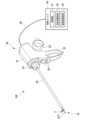
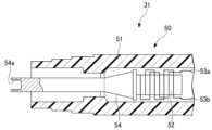
Fig. 1 is a schematic perspective view showing an example of an ultrasonic treatment device according to an embodiment of the present invention, Fig. 2 is a schematic cross-sectional view showing an example of a transducer unit in the ultrasonic treatment device according to an embodiment of the present invention.
図1に示すように、本実施形態に係る超音波処置具100は、処置部10と、シャフト20と、操作部30と、電源ユニット40とを備える。
処置部10、シャフト20、および操作部30は、シャフト20の長手方向に沿って、この順に配置されている。処置部10は、超音波処置具100の先端部を構成する。操作部30は、超音波処置具100の基端部を構成する。 As shown in FIG. 1 , an
The
処置部10は、処置対象である生体組織(例えば血管など)を把持し、把持した生体組織に高周波電圧を印加して、この生体組織を封止したり凝固させたりする。さらに、処置部10は、把持した生体組織を、超音波振動を用いて封止等しながら切断する。
処置部10は、プローブ処置部1aと、ジョー2と、を有する。
プローブ処置部1aは、プローブ1(基材)の先端部に設けられている。
プローブ1は、シャフト20の内部に挿通されて、操作部30まで延びる棒状部材である。プローブ1は、基端部において超音波振動が印加される。これにより、プローブ1は、長手方向に超音波振動し、プローブ処置部1aに接触した生体組織に超音波振動を伝達する。
本実施形態では、プローブ1には高周波電圧も印加可能である。
プローブ1の詳細構成は後述する。 The treatment unit 10 grasps a biological tissue (e.g., a blood vessel) to be treated, and applies a high-frequency voltage to the grasped biological tissue to seal or coagulate the biological tissue. Furthermore, the
The
The
The
In this embodiment, a high frequency voltage can also be applied to the
The detailed configuration of the
ジョー2は、プローブ処置部1aに対して開閉動作可能に設けられている。ジョー2がプローブ処置部1aに対して、開閉動作することによって、プローブ処置部1aとジョー2とは、生体組織は把持する。
プローブ処置部1aの一部とジョー2の一部とは、把持した生体組織に高周波電圧を印加するバイポーラ電極として機能する。ただし、プローブ処置部1aの一部とジョー2の一部はモノポーラ電極として機能してもよい。 The
A part of the
シャフト20は、中空のシースを含む。シャフト20のシースの内部には、プローブ1が配置されている。
シャフト20の先端部には、ジョー2が開閉動作可能に固定されている。
プローブ1のプローブ処置部1aは、シャフト20の先端部からより先端側に延出している。 The
A
The
操作部30には、操作部本体31と、固定ハンドル32と、可動ハンドル33と、回転ノブ34と、出力スイッチ35とが設けられている。The
図2に示すように、操作部本体31の内部には、超音波振動子ユニット50が設けられている。
超音波振動子ユニット50は、振動子ケース51を有する。振動子ケース51の内部には、逆圧電効果によって超音波振動を発生する超音波振動子52が設けられている。
超音波振動子52には、電気信号線53a、53bが接続されている。
電気信号線53a、53bは、電源ユニット40と電気的に接続されている。電気信号線53a、53bには、電源ユニット40から、超音波振動子52を超音波振動させる駆動信号が供給される。
超音波振動子52の先端部には、超音波振動の振幅を拡大するために、柱状のホーン54が連結されている。ホーン54は、振動子ケース51によって支持されている。ホーン54の先端部には、雌ネジ部54aが形成されている。 As shown in FIG. 2, an
The
The
The
A
図1に示すように、固定ハンドル32は、操作部本体31に対して固定されている。
可動ハンドル33は、操作部本体31に対して変位する。可動ハンドル33は、操作部本体31の内部において、シャフト20内を挿通してジョー2に接続されたワイヤまたはロッドに接続されている。術者の操作に基づく可動ハンドル33の変位は、可動ハンドル33が接続するワイヤまたはロッドを通して、ジョー2に伝達される。これにより、ジョー2は、可動ハンドル33の動きに応じて、プローブ処置部1aに対して変位する。 As shown in FIG. 1 , the
The
回転ノブ34は、シャフト20および処置部10を回転させる操作を行うために設けられている。回転ノブ34は、操作部本体31の先端部において、シャフト20の中心軸線回りに回転移動可能に取り付けられている。術者が、回転ノブ34を回転させると、回転量に応じて、処置部10およびシャフト20が回転する。これにより、操作部30に対する処置部10のシャフト20回りの角度が調整される。The
出力スイッチ35は、例えば2つのボタンを含む。一方のボタンが押圧されたとき、出力スイッチ35は、処置部10によって高周波電圧の印加と超音波振動子の駆動とが行われるための信号を出力する。その結果、処置部10で把持された生体組織は、封止または凝固され、切断される。また、他方のボタンが押圧されたとき、出力スイッチ35は、処置部10によって高周波電圧の印加のみが行われて超音波振動子の駆動が行われないための信号を出力する。その結果、処置部10で把持された生体組織は、切断されずに、封止または凝固される。The
操作部30の基端側には、ケーブル36の一端が接続されている。ケーブル36の他端は、電源ユニット40に接続されている。
ケーブル36の内部には、電気信号線53a、53bと、プローブ処置部1aおよびジョー2に高周波電力を印加する電気信号線と、が挿通されている。 One end of a
電源ユニット40は、制御部41と、超音波駆動部42と、高周波駆動部43とを含む。
制御部41は、超音波処置具100の各部の制御を行う。例えば制御部41は、出力スイッチ35からの操作入力に応じて、超音波駆動部42および高周波駆動部43の動作を制御する。
超音波駆動部42は、制御部41から送出される制御信号に応じて、超音波振動子52(図2参照)を駆動する。超音波駆動部42の駆動信号は、ケーブル36内に挿通される電気信号線53a、53b(図2参照)を通して、超音波振動子52に印加される。
高周波駆動部43は、制御部41から送出される制御信号に応じて、処置部10に高周波電流を供給する。高周波電力は、ケーブル36内に挿通される図示略の電気信号線を通して、バイポーラ電極を構成するプローブ処置部1aおよびジョー2に印加される。 The
The
The
The high-
プローブ1の詳細形状を説明する。
図3は、本発明の実施形態に係る超音波処置具用プローブの示す模式的な正面図である。 The detailed shape of the
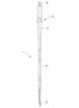
FIG. 3 is a schematic front view showing an ultrasonic treatment instrument probe according to an embodiment of the present invention.
図3に示すように、プローブ1の外形は、全体としては、直線状の軸線Oに沿う棒状である。プローブ1の外形は、長手方向において、部分的に変化している。
例えば、プローブ処置部1aは、ジョー2の閉動作の位置において、ジョー2との間に生体組織を挟むことができるように、軸線Oに交差する方向にわずかに湾曲している。
プローブ処置部1aの基端側には、軸線Oを中心として、略一定の外径を有する円柱状の円柱部1bが延びている。
円柱部1bの基端側には、操作部本体31において固定する適宜形状が形成された基端部1cが延びている。
基端部1cの基端には、ホーン54の雌ネジ部54a(図2参照)に螺合する雄ネジ部1dが設けられている。
雄ネジ部1dが雌ネジ部54aに螺合されてホーン54に連結されると、超音波振動子52で発生した超音波振動は、ホーン54を介して、プローブ処置部1aまで伝達される。 3, the outer shape of the
For example, the
A
A
The base end of the
When the male threaded
プローブ1は、組織としてトルースタイトおよびソルバイトの一方または両方を含むステンレス鋼を有する基材を備える。例えば、プローブ1は、基材とその他の部材との組合せによって形成されてよいが、印加された超音波振動に共振する部位は基材で形成されることがより好ましい。
図3に示す例では、プローブ1は、基材のみで形成されている。 The
In the example shown in FIG. 3, the
プローブ1に用いるステンレス鋼の種類は、トルースタイトおよびソルバイトの一方または両方が形成できれば、特に限定されない。The type of stainless steel used in
トルースタイトは、フェライトと、微細な炭化物粒子との混合組織であり、マルテンサイトを約400℃程度の温度で焼戻した際に形成される組織である。
ソルバイトは、マルテンサイトを約500℃から約650℃程度の温度で焼戻しした際に生じる組織であり、トルースタイトと同様、フェライトと、微細な炭化物粒子との混合組織である。ただし、ソルバイトにおける炭化物粒子の粒径は、トルースタイトに比べると大きく、粒子間距離も大きくなる。このため、ソルバイトよりもトルースタイトの方がより微細で緻密な組織である。 Troostite is a mixed structure of ferrite and fine carbide particles, and is formed when martensite is tempered at a temperature of about 400°C.
Sorbite is a structure that is formed when martensite is tempered at a temperature of about 500°C to about 650°C, and like troostite, it is a mixed structure of ferrite and fine carbide particles. However, the particle size of the carbide particles in sorbite is larger than that of troostite, and the distance between the particles is also larger. Therefore, troostite has a finer and denser structure than sorbite.
例えば、ステンレス鋼を1010℃以上1070℃以下の温度で保持した後、臨界冷却速度以上の冷却速度で焼入れすると、マルテンサイトが得られる。この後、ステンレス鋼を、例えば、350℃以上700℃以下の温度で焼戻しすると、トルースタイトおよびソルバイトの一方または両方を含む組織が得られる。
特に、350℃以上450℃以下の温度で焼戻しすると、トルースタイトの割合が多くなるので、炭化物粒子の粒子間距離の平均値が0.5μm以下になる。
ステンレス鋼に含まれるトルースタイトとソルバイトとは、組織を高倍率で顕微鏡観察することによって、判別することができる。 For example, martensite is obtained when stainless steel is held at a temperature of 1010° C. to 1070° C. and then quenched at a cooling rate equal to or higher than the critical cooling rate. If the stainless steel is then tempered at a temperature of, for example, 350° C. to 700° C., a structure containing one or both of troostite and sorbite is obtained.
In particular, when tempering is performed at a temperature of 350° C. or higher and 450° C. or lower, the proportion of troostite increases, so that the average interparticle distance of the carbide particles becomes 0.5 μm or less.
Troostite and sorbite contained in stainless steel can be distinguished by observing the structure under a microscope at high magnification.
例えば、炭化物粒子を含む鋼の組織であって、光学顕微鏡を用いて明瞭に炭化物粒子が観察できればソルバイトであり、電子顕微鏡でないと明瞭に炭化物粒子を観察できない場合にはトルースタイトとされる。光学顕微鏡の分解能は0.2μm程度なので、0.2μm以下の炭化物粒子が多い場合には、トルースタイトであるとも言える。ただし、種々の粒子径を有する炭化物粒子が混在する場合は、トルースタイトとソルバイトとの両方を含む状態であり、それぞれの区画を明瞭に区別することはできない場合がある。
ソルバイトは炭化物粒子の析出が進んだ段階の組織であるため、多くの炭化物粒子がフェライトから独立して存在していることが観察される。これに対して、トルースタイトは析出途上の炭化物粒子を含む組織であるため、一部の炭化物粒子とフェライトとが結合して存在することが観察される。
トルースタイトおよびソルバイトは、炭化物粒子が、高温焼戻しに特有の粒径と粒子形状とを有しており、当業者であれば、例えば、炭化物粒子を有しない鋼組織、セメンタイトを含むフェライト、ベイナイトなどとは、明瞭に区別できる。
以下では、トルースタイトおよびソルバイトの一方または両方を「高温焼戻し組織」と称する。 For example, if the structure of a steel contains carbide particles and the carbide particles can be clearly observed using an optical microscope, it is sorbite, and if the carbide particles can only be clearly observed using an electron microscope, it is troostite. Since the resolution of an optical microscope is about 0.2 μm, if there are many carbide particles of 0.2 μm or less, it can also be said to be troostite. However, if carbide particles with various particle sizes are mixed, it contains both troostite and sorbite, and it may not be possible to clearly distinguish between the sections.
Sorbite is a structure in which carbide particles have already precipitated, and many carbide particles are observed to exist independently of ferrite. In contrast, troostite is a structure that contains carbide particles in the process of precipitating, and some of the carbide particles are observed to exist in a combined state with ferrite.
Troostite and sorbite are carbide particles having a particle size and shape specific to high-temperature tempering, and a person skilled in the art can clearly distinguish them from, for example, a steel structure not having carbide particles, ferrite containing cementite, bainite, etc.
Hereinafter, one or both of troostite and sorbite will be referred to as "high-temperature tempered structure".
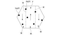
図4は、本発明の実施形態に係る超音波処置具用プローブにおける基材の組織の例を示す模式図である。
図4に結晶粒の内部の断面を模式的に示すように、高温焼戻し組織を有するステンレス鋼では、フェライトFと、炭化物粒子Pと、が混合している。
フィライトFは、複数の磁区Mに分かれている。各磁区Mは、矢印で模式的に示す磁気モーメントの方向が隣り合う他の磁区Mと異なっており、互いに隣り合う磁区Mの間には、磁気モーメントの方向が遷移する磁壁Wが形成されている。
ただし、図4は、模式図のため、磁区Mの数および大きさと、炭化物粒子Pの数および大きさと、を正確に表しているわけではない。
ステンレス鋼における結晶粒の粒径は、発熱を抑制しやすくなる点で、大きすぎないことがより好ましい。例えば、結晶粒の粒径は、1μm以上10μm以下であることがより好ましい。 FIG. 4 is a schematic diagram showing an example of the structure of a base material in an ultrasonic treatment instrument probe according to an embodiment of the present invention.
As shown in FIG. 4, which is a schematic diagram of a cross section of the inside of a crystal grain, ferrite F and carbide particles P are mixed in stainless steel having a high-temperature tempered structure.
The phyllite F is divided into a plurality of magnetic domains M. The direction of the magnetic moment of each magnetic domain M, which is indicated by an arrow, differs from that of the adjacent magnetic domains M, and a domain wall W is formed between the adjacent magnetic domains M, where the direction of the magnetic moment transitions.
However, since FIG. 4 is a schematic diagram, the number and size of the magnetic domains M and the number and size of the carbide grains P are not accurately shown.
It is preferable that the grain size of the crystal grains in the stainless steel is not too large, since this makes it easier to suppress heat generation. For example, it is more preferable that the grain size of the crystal grains is 1 μm or more and 10 μm or less.
炭化物粒子Pは、ステンレス鋼における炭素含有量に応じて形成されている。炭化物粒子Pは、焼戻し温度等の析出条件に応じた粒子径を有し、金属結晶の内部において互いに離れて分布している。
炭化物粒子Pは、フェライトFの磁気的性質と関係なくランダムに析出するので、粒子数がある程度多くなると、一部の炭化物粒子Pは磁壁W上に析出する。例えば、図4において炭化物粒子Paは、磁区M内の炭化物粒子Pであり、炭化物粒子Pbは磁壁W上の炭化物粒子Pを示す。
炭化物粒子Pbは、磁壁Wの移動を阻害するので、磁壁Wは炭化物粒子Pによってピン止めされたような状態になっている。
炭化物粒子Pの粒子数によっては、炭化物粒子Pbが存在せず、すべての炭化物粒子Pが炭化物粒子Paである可能性もある。しかし、炭化物粒子Pの粒子間距離が磁区Mの大きさに比べて小さければ、炭化物粒子Pは、各磁区Mの近くに存在する。この場合、磁壁Wが移動しても、炭化物粒子Paの位置に到達すると、炭化物粒子Paによって磁壁Wの移動が阻害されるので、磁壁Wの移動が停止する。これにより、磁壁Wは、移動経路に存在する炭化物粒子Paによってピン止めされたような状態になる。
このように、結晶内に炭化物粒子Pが適正に存在すると、磁壁Wの移動が制限される。 The carbide particles P are formed according to the carbon content of the stainless steel. The carbide particles P have a particle size according to the precipitation conditions such as the tempering temperature, and are distributed separately from each other inside the metal crystal.
Since the carbide particles P precipitate randomly regardless of the magnetic properties of the ferrite F, when the number of particles increases to a certain extent, some of the carbide particles P precipitate on the domain wall W. For example, in FIG. 4, carbide particle Pa is a carbide particle P in the magnetic domain M, and carbide particle Pb is a carbide particle P on the domain wall W.
The carbide particles Pb inhibit the movement of the domain wall W, so that the domain wall W is in a state of being pinned by the carbide particles P.
Depending on the number of carbide particles P, there may be no carbide particles Pb, and all carbide particles P may be carbide particles Pa. However, if the interparticle distance between carbide particles P is small compared to the size of magnetic domains M, carbide particles P are present near each magnetic domain M. In this case, even if the domain wall W moves, when it reaches the position of a carbide particle Pa, the movement of the domain wall W is hindered by the carbide particle Pa, and the movement of the domain wall W stops. As a result, the domain wall W is in a state of being pinned by the carbide particles Pa present in its movement path.
In this way, when the carbide grains P are appropriately present in the crystal, the movement of the domain wall W is restricted.
プローブ1に用いるステンレス鋼の高温焼戻し組織では、磁壁Wに重なる位置または磁壁Wの近くに、より多く炭化物粒子Pが形成されることがより好ましい。
例えば、高温焼戻し組織における炭化物粒子Pの粒子間距離の平均値は、0.5μm以下であることがより好ましい。この場合、高温焼戻し組織がより緻密になり、炭化物粒子Pが磁壁Wに重なる位置または磁壁Wの近くに位置しやすくなる。
ここで、炭化物粒子Pの粒子間距離は、炭化物粒子Pの中心間距離で定義される。粒子間距離は、組織の画像から測定できる。
例えば、プローブ1に用いるステンレス鋼は、0.95質量%以上1.2質量%以下の炭素を含有することがより好ましい。この場合、高温焼戻し組織における炭化物粒子Pの粒子数が適正となる。これにより、高温焼戻し組織がより緻密になり、炭化物粒子Pが磁壁Wに重なる位置または磁壁Wの近くに位置しやすくなる。 In the high-temperature tempered structure of the stainless steel used in the
For example, it is more preferable that the average interparticle distance of the carbide grains P in the high-temperature tempered structure is 0.5 μm or less. In this case, the high-temperature tempered structure becomes denser, and the carbide grains P are more likely to be located in positions overlapping with or near the domain walls W.
Here, the interparticle distance of the carbide particles P is defined as the center-to-center distance of the carbide particles P. The interparticle distance can be measured from an image of the structure.
For example, the stainless steel used for the
ステンレス鋼において炭化物粒子Pが多くなると、耐食性が低下する可能性がある。耐食性の低下を抑制するためには、ステンレス鋼は、16質量%以上18質量%以下のクロムを含有することがより好ましい。If the amount of carbide particles P in stainless steel increases, the corrosion resistance may decrease. In order to prevent the deterioration of corrosion resistance, it is more preferable that the stainless steel contains 16% by mass or more and 18% by mass or less of chromium.
プローブ1の製造方法の例を説明する。
プローブ1は、以下に説明する第1工程、第2工程、および第3工程をこの順に行うことによって製造される。
第1工程では、ステンレス鋼の素材からプローブ1の形状を有する基材を形成する。例えば、プローブ1の全体が基材の場合、ステンレス鋼の素材から、プローブ1の形状を形成する。
ステンレス鋼の素材としては、0.95質量%以上1.2質量%以下の炭素を含有することがより好ましく、16質量%以上18質量%以下のクロムを含有することがさらに好ましい。
例えば、ステンレス鋼の素材としては、SUS440Cが用いられてもよい。 An example of a method for manufacturing the
The
In the first step, a base material having the shape of the
The stainless steel material more preferably contains 0.95% by mass or more and 1.2% by mass or less of carbon, and even more preferably contains 16% by mass or more and 18% by mass or less of chromium.
For example, SUS440C may be used as the stainless steel material.
第1工程の後、第2工程が行われる。
第2工程では、第1工程で形成した基材を、マルテンサイトにするため、焼き入れする。例えば、基材を1010℃以上1070℃以下の温度で保持し、臨界冷却速度以上の冷却速度で焼入れする。 After the first step, the second step is carried out.
In the second step, the substrate formed in the first step is quenched to convert it to martensite. For example, the substrate is held at a temperature of 1010° C. or higher and 1070° C. or lower, and quenched at a cooling rate equal to or higher than the critical cooling rate.
第2工程の後、第3工程が行われる。
第3工程では、第2工程で焼入れされた基材のマルテンサイトから高温焼戻し組織が形成されるように、基材を焼戻しする。例えば、高温焼戻し組織が主としてトルースタイトになるようにするには、基材を、350℃以上450℃以下の温度で焼戻しすればよい。この場合、炭化物粒子の粒子間距離の平均値を0.5μm以下にできる。
ただし、高温焼戻し組織にソルバイトを含める場合には、450℃を超え700℃以下の温度で焼戻してもよい。この場合、高温になるほど、ソルバイトの割合が増大する。
以上で、高温焼戻し組織を含むステンレス鋼からなるプローブ1が製造できる。 After the second step, the third step is carried out.
In the third step, the base material is tempered so that a high-temperature tempered structure is formed from the martensite of the base material quenched in the second step. For example, in order to make the high-temperature tempered structure mainly troostite, the base material may be tempered at a temperature of 350° C. or more and 450° C. or less. In this case, the average interparticle distance of the carbide particles can be set to 0.5 μm or less.
However, when sorbite is contained in the high-temperature tempered structure, the steel may be tempered at a temperature of more than 450° C. and not more than 700° C. In this case, the higher the temperature, the greater the proportion of sorbite.
In this manner, the
本実施形態に係る超音波処置具100の動作について説明する。
術者は、電源ユニット40の入力部を操作して、超音波処置具100の出力条件、例えば、高周波エネルギーの出力の設定電力、超音波エネルギーの出力の設定電力等を設定しておく。超音波処置具100は、それぞれの値が個別に設定されるようになっていてもよいし、術式に応じた設定値のセットが選択されるようになっていてもよい。 The operation of the
The surgeon operates the input section of the
超音波処置具100の処置部10およびシャフト20は、例えば、腹壁を通して腹腔内に挿入される。術者は、可動ハンドル33を操作して処置部10を開閉させ、プローブ処置部1aとジョー2とによって処置対象である生体組織を把持する。
術者は、処置部10で生体組織を把持したら、出力スイッチ35を操作する。2つある出力スイッチ35のうち、一方のボタンが押圧されたとき、出力スイッチ35は、処置部10によって高周波電圧の印加と超音波振動子の駆動とが行われるための信号を出力する。この場合、電源ユニット40の制御部41は、超音波駆動部42および高周波駆動部43に駆動信号を送出する。 The
When the surgeon grasps the biological tissue with the
高周波駆動部43は、制御部41からの制御信号に基づいて、処置部10のプローブ処置部1aおよびジョー2に高周波電圧を印加し、処置対象である生体組織に高周波電流を流す。高周波電流が流れると、生体組織の電気的な抵抗に応じて、生体組織で熱が発生し、生体組織の温度が上昇する。このときの生体組織の温度は、例えば100℃程度になる。この結果、生体組織のタンパク質が変成し、生体組織が凝固し封止される。Based on a control signal from the
超音波駆動部42は、制御部41からの制御信号に基づいて、超音波振動子52を駆動する。これにより、プローブ処置部1aは、超音波振動子52の駆動周波数に応じて、長手方向に超音波振動する。このとき、駆動周波数がプローブ1の固有振動数に近付くことによってプローブ1が共振すると、超音波振動が増幅される。共振状態では超音波振動のエネルギーが効率的に生体組織に伝達される。
超音波振動するプローブ処置部1aと生体組織との摩擦熱によって、生体組織の温度が上昇する。この結果、生体組織のタンパク質が変成し、生体組織が凝固し封止される。
超音波振動による生体組織の封止効果は、高周波電圧の印加による封止効果よりも弱い。また、生体組織の温度は、例えば200℃程度になる。その結果、生体組織は崩壊し、生体組織は切断される。このように、処置部10で把持された生体組織は、凝固して封止された状態で切断される。
このようにして、超音波処置具100による生体組織の処置が終了する。 The
The temperature of the living tissue rises due to frictional heat between the ultrasonically vibrating
The sealing effect of the biological tissue by ultrasonic vibration is weaker than that by application of high frequency voltage. Also, the temperature of the biological tissue becomes, for example, about 200°C. As a result, the biological tissue collapses and is cut. In this way, the biological tissue grasped by the
In this manner, the treatment of the living tissue by the
超音波処置具における従来のステンレス鋼製のプローブでは、例えば、チタン合金製のプローブに比べて超音波振動時の発熱量が多いことが知られている。従来のステンレス鋼のプローブが、ある程度、連続的に超音波振動すると、プローブ全体の温度上昇によってヤング率が低下し、プローブの固有振動数が変化する。これにより、共振周波数も変化するので、超音波振動の振幅が格段に小さくなり、処置が継続できなくなるという問題がある。It is known that conventional stainless steel probes in ultrasonic treatment instruments generate more heat during ultrasonic vibration than, for example, titanium alloy probes. When a conventional stainless steel probe is subjected to continuous ultrasonic vibration for a certain period of time, the Young's modulus decreases due to an increase in temperature of the entire probe, and the natural vibration frequency of the probe changes. This causes the resonant frequency to change, resulting in a significant decrease in the amplitude of the ultrasonic vibration, and the problem of being unable to continue treatment.
本発明者は、超音波処置具におけるステンレス鋼製のプローブの発熱を処置に支障ない程度まで抑制することを目的として鋭意研究したところ、高温焼戻し組織を含むステンレス鋼を用いてプローブを形成することによって、発熱を抑制できることを見出し、本発明に到った。
本発明者は、ステンレス鋼の発熱成分として、超音波振動によって誘起される磁壁の移動に起因すると推定されるエネルギー損失に着目し、金属結晶に炭化物粒子を分布させることに想到した。 The inventors conducted extensive research with the aim of suppressing heat generation in stainless steel probes in ultrasonic treatment instruments to a level that would not interfere with treatment, and discovered that heat generation can be suppressed by forming the probe using stainless steel that contains a high-temperature tempered structure, thereby arriving at the present invention.
The inventors focused on the energy loss presumably caused by the movement of domain walls induced by ultrasonic vibration as a heat generating component of stainless steel, and came up with the idea of distributing carbide particles in metal crystals.
まず、炭化物粒子Pが存在しないステンレス鋼を用いた比較例のプローブの作用を説明する。
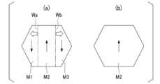
図5は、比較例に係る超音波処置具用プローブの作用を示す模式図である。
図5における(a)に、炭化物粒子Pが存在しないステンレス鋼を用いた比較例のプローブの金属結晶を模式的に示す。比較例のプローブの金属結晶において、磁区M1、M2、M3が形成されているとする。
比較例のプローブを超音波振動させると、強磁性体における磁歪逆効果により超音波振動によって発生する応力に応じて磁壁が移動する。例えば、磁区M1、M2の間の磁壁Waと、磁区M2、M3の間の磁壁Wbと、が、それぞれ白抜き矢印で示す方向に移動する。この場合、磁壁Wa、Wbの移動が終了すると、図5における(b)に示すように、磁区M1、M3が消失し、磁区M2のみが残る。
磁壁Wa、Wbの移動が移動し、磁気モーメントの向きが変化することにより、金属結晶内に渦電流損失(eddy current loss)が発生したり、ヒステリシス型の磁気-機械的ヒステリシス損失(magnetomechanical hysteresis loss)が発生したりする。これらのエネルギー損失は、磁気内部摩擦(magnetic damping)とも呼ばれている。このような磁気内部摩擦によれば、比較例のプローブに発熱が生じる。 First, the function of the comparative probe using stainless steel in which no carbide particles P are present will be described.
FIG. 5 is a schematic diagram showing the operation of the ultrasonic treatment instrument probe according to the comparative example.
5A is a schematic diagram showing a metal crystal of a comparative probe using stainless steel that does not contain carbide particles P. It is assumed that magnetic domains M1, M2, and M3 are formed in the metal crystal of the comparative probe.
When the comparative probe is ultrasonically vibrated, the magnetic domain walls move in response to the stress generated by the ultrasonic vibration due to the magnetostrictive reverse effect in the ferromagnetic material. For example, the magnetic domain wall Wa between the magnetic domains M1 and M2 and the magnetic domain wall Wb between the magnetic domains M2 and M3 move in the directions indicated by the white arrows. In this case, when the movement of the magnetic domain walls Wa and Wb is completed, the magnetic domains M1 and M3 disappear, and only the magnetic domain M2 remains, as shown in FIG. 5B.
The movement of the domain walls Wa and Wb causes the direction of the magnetic moment to change, which generates eddy current loss in the metal crystal and magnetomechanical hysteresis loss of the hysteresis type. These energy losses are also called magnetic internal friction. Such magnetic internal friction generates heat in the comparative probe.
図6は、本発明の実施形態に係る超音波処置具用プローブの作用を示す模式図である。
図6における(a)に示す本実施形態のプローブ1の金属結晶は、炭化物粒子Pが析出していることを除くと、比較例のプローブの金属結晶と同様である。
磁壁Wa、Wb上に位置する炭化物粒子Pbは磁壁Wa、Wbの移動を阻害する機能を有する。これにより、プローブ1を超音波振動させても、図6における(b)に示すように、磁壁Wa、Wbが移動せず、磁区M1、M2、M3は、超音波振動している間、変化しない。
この結果、磁壁Wa、Wbの移動によるエネルギー損失が生じないので、磁壁Wa、Wbの移動に伴う発熱が抑制される。 FIG. 6 is a schematic diagram showing the operation of the ultrasonic treatment device probe according to the embodiment of the present invention.
The metal crystals of the
The carbide particles Pb located on the magnetic domain walls Wa, Wb have the function of inhibiting the movement of the magnetic domain walls Wa, Wb, so that even if the
As a result, no energy loss occurs due to the movement of the domain walls Wa, Wb, and therefore the heat generation accompanying the movement of the domain walls Wa, Wb is suppressed.
このように、プローブ1では、超音波振動を伝達する際に、磁壁の移動に伴う発熱が抑制されるので、温度上昇が低減される。これにより、温度上昇に伴うプローブ1の固有振動数の変化が抑制されるので、超音波駆動部42の駆動周波数が一定でも、生体組織に安定して超音波振動を伝達できる。In this way, when the
本実施形態のプローブ1およびプローブ1を備える超音波処置具100によれば、プローブ1に含まれるステンレス鋼の組織に、トルースタイトおよびソルバイトの一方または両方を含むので、プローブ1のステンレス鋼における発熱を抑制することができる。このため、例えば、プローブ1の温度制御をしたり、超音波駆動部42の駆動周波数を調整したりすることなく、長時間、処置を継続することができる。例えば、従来のステンレス鋼製のプローブでは、20秒程度しか処置を継続できないところ、プローブ1によれば、4分程度、連続的に処置を継続することができる。
プローブ1は、超音波振動時の温度変化が抑制されるので、固有振動数の調整機構などを有する必要がない。このため、簡素な構成によって、温度制御することなく長時間使用可能である。 According to the
Since the temperature change during ultrasonic vibration is suppressed, the
本実施形態に係る超音波処置具用プローブの製造方法によれば、規格品のステンレス鋼を熱処理することによってトルースタイトおよびソルバイトの一方または両方を含む組織が形成できる。これにより、レアメタル元素など含有する高価な合金を用いることなく、発熱を抑制できるので、プローブ1の製造コストを低減できる。プローブ1の熱処理は、ステンレス鋼の形状をプローブ1の形状に形成した後に行うことができるので、プローブの形状によらず、発熱を抑制することができる。
このような本実施形態に係るプローブ1は、安価に製造することができるので、滅菌処理の手間を省くことができるシングルユースに好適である。 According to the manufacturing method of the ultrasonic treatment instrument probe of this embodiment, a structure containing one or both of troostite and sorbite can be formed by heat treating standard stainless steel. This makes it possible to suppress heat generation without using expensive alloys containing rare metal elements, etc., thereby reducing the manufacturing cost of the
The
以上説明したように、プローブ1およびプローブ1を備える超音波処置具100によれば、プローブの材料にステンレス鋼を含む場合に発熱を抑制することができ、温度制御することなく長時間使用可能である。As described above, with the
なお、上記実施形態の説明では、超音波処置具の処置部10が、生体組織を挟んで処置を行う鉗子型の例で説明した。しかし、超音波処置具の種類は鉗子型には限定されない。例えば、超音波処置具の処置部は、生体組織を処置部によって挟持することなく、プローブを生体組織に押し付けて処置を行う、鋸型、スパイク型、肉たたき型などであってもよい。In the above embodiment, the
次に、実施形態に関する実施例1~4について、比較例1~3とともに説明する。
下記[表1]に、実施例1~4および比較例1~3のプローブを製造したステンレス鋼の組成を示した。 Next, Examples 1 to 4 relating to the embodiment will be described together with Comparative Examples 1 to 3.
The compositions of the stainless steels used to manufacture the probes of Examples 1 to 4 and Comparative Examples 1 to 3 are shown in Table 1 below.

下記[表2]に、実施例1~4および比較例1~3のプローブの熱処理条件と、評価結果と、を示した。The heat treatment conditions and evaluation results for the probes of Examples 1 to 4 and Comparative Examples 1 to 3 are shown in Table 2 below.

[実施例1]
[表1]に示すように、実施例1のプローブ1を製造したステンレス鋼の素材としては、SUS440Cが用いられた。素材の形状は、直径8mmの丸棒材であった。
素材の組成は、炭素(C)が0.98質量%、珪素(Si)が0.27質量%、マンガン(Mn)が0.31質量%、リン(P)が0.02質量%、硫黄(S)が0.002質量%、ニッケル(Ni)が0.15質量%、クロム(Cr)が16.9質量%であった。
素材は、旋盤加工によって、図3に示すようなプローブ1の形状に形成された(第1工程)。
この後、プローブ1の形状に形成された部品は、[表1]に示す熱処理条件に基づいて焼入れされた(第2工程)。
第2工程では、部品が1040℃の焼入れ温度において熱処理炉に10分間保持された。この後、部品は、臨界冷却速度以上の冷却速度で油冷された。これにより部品の焼入れが終了した。
この後、焼入れされた部品は、[表1]に示す熱処理条件に基づいて焼戻しされた(第3工程)。
第3工程では、部品が400℃の焼戻し温度において熱処理炉に1時間保持された。この後、部品は、常温まで油冷された。これにより部品の焼戻しが終了した。
以上で、実施例1のプローブ1が製造された。[Example 1]
As shown in Table 1, SUS440C was used as the stainless steel material for manufacturing the
The composition of the material was 0.98 mass% carbon (C), 0.27 mass% silicon (Si), 0.31 mass% manganese (Mn), 0.02 mass% phosphorus (P), 0.002 mass% sulfur (S), 0.15 mass% nickel (Ni), and 16.9 mass% chromium (Cr).
The material was turned on a lathe into the shape of the
Thereafter, the part formed into the shape of the
In the second step, the part was held in a heat treatment furnace at a quenching temperature of 1040° C. for 10 minutes. After this, the part was oil-quenched at a cooling rate equal to or higher than the critical cooling rate, thereby completing the quenching of the part.
Thereafter, the quenched parts were tempered based on the heat treatment conditions shown in Table 1 (third step).
In the third step, the part was held in a heat treatment furnace at a tempering temperature of 400° C. for 1 hour. After this, the part was oil-cooled to room temperature, thereby completing the tempering of the part.
In this manner, the
[実施例2~4]
[表1]に示すように、実施例2~4のプローブ1を製造したステンレス鋼の素材は、実施例1の素材と同様であった。
実施例2~4のプローブ1の製造方法は、[表2]に示すように、焼戻し温度が異なる以外は、実施例1と同様であった。
実施例2における第3工程では、焼戻し温度は350℃とされた。
実施例3における第3工程では、焼戻し温度は450℃とされた。
実施例4における第3工程では、焼戻し温度は500℃とされた。[Examples 2 to 4]
As shown in Table 1, the stainless steel material from which the
The manufacturing method of the
In the third step in Example 2, the tempering temperature was set to 350°C.
In the third step in Example 3, the tempering temperature was set to 450°C.
In the third step in Example 4, the tempering temperature was set to 500°C.
[比較例1]
[表1]に示すように、比較例1のプローブを製造したステンレス鋼の素材としては、SUS304が用いられた。素材の形状は、直径8mmの丸棒材であった。
素材の組成は、炭素(C)が0.04質量%、珪素(Si)が0.5質量%、マンガン(Mn)が1.5質量%、リン(P)が0.02質量%、硫黄(S)が0.015質量%、ニッケル(Ni)が9.2質量%、クロム(Cr)が19質量%であった。
比較例1の製造方法は、[表2]に示すように、素材の材料が異なる以外は、実施例1と同様であった。[Comparative Example 1]
As shown in Table 1, SUS304 was used as the stainless steel material for manufacturing the probe of Comparative Example 1. The shape of the material was a round bar with a diameter of 8 mm.
The composition of the material was 0.04 mass% carbon (C), 0.5 mass% silicon (Si), 1.5 mass% manganese (Mn), 0.02 mass% phosphorus (P), 0.015 mass% sulfur (S), 9.2 mass% nickel (Ni), and 19 mass% chromium (Cr).
The manufacturing method of Comparative Example 1 was the same as that of Example 1, except that the raw material was different, as shown in Table 2.
[比較例2]
[表1]、[表2]に示すように、比較例2のプローブは、焼戻し温度が300℃とされたことを除くと、実施例1と同様に製造された。[Comparative Example 2]
As shown in Tables 1 and 2, the probe of Comparative Example 2 was manufactured in the same manner as in Example 1, except that the tempering temperature was set to 300°C.
[比較例3]
[表1]、[表2]に示すように、比較例3のプローブは、焼戻しの実施がなされていないことを除くと、実施例1と同様に製造された。[Comparative Example 3]
As shown in Tables 1 and 2, the probe of Comparative Example 3 was manufactured in the same manner as in Example 1, except that tempering was not carried out.
[評価]
製造された各実施例、各比較例のプローブを用いて、組織の判定と、炭化物粒子の粒子間距離の測定と、プローブの温度上昇の測定とが実施された。[evaluation]
Using the manufactured probes of each of the examples and comparative examples, the structure was evaluated, the interparticle distances of the carbide particles were measured, and the temperature rise of the probe was measured.
[組織の判定]
組織の判定は、X線回折測定(XRD)オーステナイトが含まれるかどうかが判定され、オーステナイトが含まれない場合に、顕微鏡観察が実施された。
各実施例および各比較例のプローブから、X線回折測定用の試料が作製された。
各試料断面について、X線回折装置Smartlab(登録商標)(商品名;(株)リガク製)を用いてプロファイル測定が行われた。管球としてはCu(20kV)が用いられ、スキャンステップは0.03°、スキャン速度は20°/minの条件で30°~110°の範囲のXRDプロファイル(2θスキャン)を得た。
本測定によれば、オーステナイトが含まれる場合、44.5°近傍のピークに加えて43°近傍にピークが存在する。両ピークが現れない場合、オーステナイトが含まれないことが分かる。
図7は、オーステナイトが含まれない場合のXRDプロファイルの例を示すグラフである。グラフの横軸は2θ(deg)、縦軸は強度(counts)である。
図7に示すグラフは、実施例4のXRDプロファイルであった。43°近傍にピークが現れなかったので、実施例4のプローブ1には、オーステナイトが含まれていなかった。[Organization Determination]
The structure was judged by X-ray diffraction measurement (XRD) to determine whether or not austenite was present, and if austenite was not present, microscopic observation was performed.
Samples for X-ray diffraction measurement were prepared from the probes of each of the examples and comparative examples.
For each sample cross section, a profile measurement was performed using an X-ray diffractometer Smartlab (registered trademark) (product name: manufactured by Rigaku Corporation). A Cu (20 kV) was used as the tube, and an XRD profile (2θ scan) was obtained in the range of 30° to 110° under the conditions of a scan step of 0.03° and a scan speed of 20°/min.
According to this measurement, when austenite is present, in addition to the peak near 44.5°, a peak is present near 43°. When both peaks do not appear, it is understood that austenite is not present.
7 is a graph showing an example of an XRD profile when austenite is not included, in which the horizontal axis represents 2θ (deg) and the vertical axis represents intensity (counts).
The graph shown in Figure 7 is an XRD profile of Example 4. Since no peak appeared near 43°,
次に、実施された顕微鏡観察を説明する。
各実施例および各比較例のプローブから、顕微鏡観察用の試料が作製された。
各試料は、エポキシ樹脂に埋められた後、断面研磨機で研磨された。耐水研磨紙(~#1500)を用いて粗研磨した後、ダイヤモンドスラリー(~0.25μm)を用いて試料表面を鏡面に仕上げ、観察用サンプルを作製した。 The microscopic observations that were performed are now described.
Samples for microscopic observation were prepared from the probes of each of the examples and comparative examples.
Each sample was embedded in epoxy resin and then polished with a cross-section polisher. After rough polishing with waterproof abrasive paper (up to #1500), the sample surface was mirror-finished with diamond slurry (up to 0.25 μm) to prepare a sample for observation.
マルテンサイトの有無を判別した組織観察法Iを説明する。
組織観察法Iでは、観察用サンプルを腐食液(硫酸銅5g、塩酸100mL、エタノール100mL、水100mL)に浸漬し、腐食させた。
腐食した観察用サンプルの組織の写真を、デジタルマイクロスコープDSX510(商品名;オリンパス(株)製)を用いて撮影した。撮影は対物レンズの倍率が40倍、ズーム倍率が6倍の条件で行われた。
得られた組織写真(グレースケール)のうち、80μm四方の測定領域を観察して、測定領域にマルテンサイトが含まれていたか、判別した。
マルテンサイトが含まれていた場合、濃い黒色の組織が観察される。マルテンサイトが含まれない場合、灰色の組織が観察される。 A structure observation method I for determining the presence or absence of martensite will be described.
In the structure observation method I, the observation sample was immersed in a corroding solution (5 g of copper sulfate, 100 mL of hydrochloric acid, 100 mL of ethanol, and 100 mL of water) and corroded.
Photographs of the corroded structure of the observation sample were taken using a digital microscope DSX510 (product name: manufactured by Olympus Corporation) with an objective lens magnification of 40 times and a zoom magnification of 6 times.
In the obtained structure photograph (gray scale), a measurement area of 80 μm square was observed to determine whether martensite was contained in the measurement area.
If martensite is present, a deep black structure is observed, whereas if martensite is not present, a gray structure is observed.
マルテンサイトが含まれなかった場合に、組織を判別した組織観察法IIを説明する。
図8は、フェライトとセメンタイトとからなる組織の観察例を示す写真である。図9は、トルースタイトおよびソルバイトを含む組織の観察例を示す写真である。図10は、ソルバイトの観察例を示す走査型電子顕微鏡による写真である。
腐食液を王水に変更した以外は、組織観察法Iと同様にして、観察用サンプルを撮影した。ただし、組織観察法IIでは、フルカラーの組織写真が撮影された。
得られた組織写真(フルカラー)のうち、80μm四方の測定領域を観察して、
フェライト+セメンタイトと、トルースタイト(ソルバイト)と、を判別した。
フェライト+セメンタイトの場合、炭化物は層状であるか、粒子状であるが、粒子状の場合でも、粒径は1μmを超えている。これに対して、トルースタイト(ソルバイト)は、炭化物が粒子状であり、粒径は1μm以下である。
フェライト+セメンタイトの場合、例えば、図7に示すような写真が撮影された。フルカラー写真の場合、図7の観察例は、白色の素地(フェライト)に黒く縁どられた円(球状セメンタイト)が多数観察され、粒径が大きかったので、トルースタイトおよびソルバイトから区別された。
トル―スタイト(ソルバイト)の場合、例えば、図8に示すような写真が撮影された。フルカラー写真の場合、茶色みがかった素地(トル―スタイト/ソルバイト)と白い粒子(炭化物)とが観察され、炭化物粒子の粒径が小さかったので、フェライト+セメンタイトの組織から区別された。
トルースタイトと、ソルバイトとの、区別は、王水で腐食した後に走査型電子顕微鏡(SEM)で観察することにより行われた。例えば、図10に示す組織は、炭化物粒子がフェライトから独立して存在していたので、ソルバイトだった。
ベイナイトに関しては、特に写真を示していないが、粒子形状が針状なので、顕微鏡観察によって、フェライト+セメンタイトおよびトル―スタイト(ソルバイト)から判別できた。 A structure observation method II for determining the structure when martensite is not contained will be described.
Fig. 8 is a photograph showing an example of an observation of a structure consisting of ferrite and cementite, Fig. 9 is a photograph showing an example of an observation of a structure containing troostite and sorbite, and Fig. 10 is a photograph taken with a scanning electron microscope showing an example of an observation of sorbite.
Except for changing the etchant to aqua regia, the observation sample was photographed in the same manner as in structure observation method I. However, in structure observation method II, full-color structure photographs were taken.
In the obtained structure photograph (full color), a measurement area of 80 μm square was observed,
Ferrite + cementite and troostite (sorbite) were distinguished.
In the case of ferrite + cementite, the carbides are either lamellar or particulate, but even in the particulate form, the grain size is greater than 1 μm, whereas in troostite (sorbite), the carbides are particulate and the grain size is less than 1 μm.
In the case of ferrite + cementite, for example, a photograph as shown in Figure 7 was taken. In the case of a full-color photograph, the observation example in Figure 7 shows a large number of circles (spherical cementite) with black outlines on a white base material (ferrite), and since the grain size was large, they could be distinguished from troostite and sorbite.
In the case of troostite (sorbite), for example, a photograph as shown in Figure 8 was taken. In the full-color photograph, a brownish matrix (troostite/sorbite) and white particles (carbide) were observed, and the carbide particles were small in size, so they could be distinguished from the ferrite + cementite structure.
The distinction between troostite and sorbite was made by observing them with a scanning electron microscope (SEM) after etching with aqua regia. For example, the structure shown in Figure 10 was sorbite because the carbide particles were separate from the ferrite.
As for bainite, no specific photograph is shown, but because the particle shape is needle-like, it can be distinguished from ferrite + cementite and troostite (sorbite) by observation under a microscope.
[炭化物粒子の粒子間距離の測定]
組織観察法IIによって、炭化物粒子が判別できた場合、炭化物粒子の中心間距離で定義される粒子間距離の測定を行った。10μm四方のSEM像の測定領域内の30個の粒子間距離から平均値を算出し、[表2]の「炭化物粒子の平均粒子間距離」欄に記載した。[Measurement of interparticle distance of carbide particles]
When carbide particles were identified by the structure observation method II, the interparticle distance, defined as the center-to-center distance of the carbide particles, was measured. The average value was calculated from 30 interparticle distances within a measurement area of a 10 μm square SEM image, and the average value was recorded in the "Average interparticle distance of carbide particles" column in [Table 2].
[プローブの温度上昇の測定]
各実施形態および各比較例のプローブを超音波駆動部42を接続して、プローブを5分間超音波振動させた。超音波駆動部42による駆動条件は、振幅30μm、駆動周波数47kHzであった。超音波振動の開始前と、終了直後のプローブの温度を放射温度計を用いて測定し、超音波振動に起因する温度上昇を測定した。[Measurement of temperature rise of the probe]
The probes of each embodiment and each comparative example were connected to an
[評価結果]
上述した組織の判定によれば、[表2]に示すように、実施例1~3の組織は主としてトルースタイトであった。実施例4の組織は主としてソルバイトであった。
比較例1、2、3の組織は、それぞれ、オーステナイト、ベイナイト、およびマルテンサイトであった。[Evaluation results]
According to the above-mentioned structure determination, the structures of Examples 1 to 3 were mainly troostite, as shown in Table 2. The structure of Example 4 was mainly sorbite.
The structures of Comparative Examples 1, 2, and 3 were austenite, bainite, and martensite, respectively.
[表2]に示すように、実施例1~4における粒子間距離の平均値は、それぞれ、0.4μm、0.3μm、0.5μm、0.7μmであった。
組織が主としてトルースタイトであった実施例1~5における粒子間距離の平均値はいずれも0.5μm以下であった。組織が主としてソルバイトであった実施例4における粒子間距離の平均値は0.5μmを超えていた。
比較例1~3には、炭化物粒子は析出していなかった。 As shown in Table 2, the average interparticle distances in Examples 1 to 4 were 0.4 μm, 0.3 μm, 0.5 μm, and 0.7 μm, respectively.
The average interparticle distance in Examples 1 to 5, in which the structure was mainly troostite, was 0.5 μm or less in all cases. The average interparticle distance in Example 4, in which the structure was mainly sorbite, exceeded 0.5 μm.
In Comparative Examples 1 to 3, no carbide particles were precipitated.
[表2]に示すように、実施例1~4における温度上昇は、それぞれ、45deg、30deg、60deg、80degであった。
比較例1~3における温度上昇は、それぞれ、300deg、175deg、200degであった。 As shown in Table 2, the temperature rises in Examples 1 to 4 were 45 degrees, 30 degrees, 60 degrees, and 80 degrees, respectively.
The temperature rises in Comparative Examples 1 to 3 were 300 degrees, 175 degrees, and 200 degrees, respectively.
各実施例および各比較例は、温度上昇の測定値に基づいて評価された。温度上昇が0deg以上75deg以下の場合は「非常に良い」(very good、[表2]には「A」と記載)、75degを超え150deg以下の場合は「良い」(good、[表2]には「B」と記載)、150degを超えた場合は不良(not good、[表2]には「C」と記載)と定義した。
[表2]に示すように、実施例1~3のプローブ1は、「非常に良い」と判定された。実施例4のプローブ1は、「良い」と判定された。
これに対して、比較例1~3はいずれも「不良」と判定された。 Each example and each comparative example was evaluated based on the measured value of the temperature rise. A temperature rise of 0 degrees or more and 75 degrees or less was defined as "very good" (listed as "A" in [Table 2]), a temperature rise of more than 75 degrees and 150 degrees or less was defined as "good" (listed as "B" in [Table 2]), and a temperature rise of more than 150 degrees was defined as "not good" (listed as "C" in [Table 2]).
As shown in Table 2, the
In contrast, all of Comparative Examples 1 to 3 were judged to be "poor."
実施例4の温度上昇が実施例1~3に比べて、大きかった理由としては、組織が主としてソルバイトだった結果、炭化物粒子の粒子間距離の平均値が0.7μmのように、大きかったことが挙げられる。炭化物粒子の粒子間距離が大きかったことで、炭化物粒子によって移動が阻害される磁壁の数が減少したと考えられる。
比較例1~3の場合、磁壁の移動を阻害する炭化物粒子の析出自体がなかったため、実施例1~4よりも温度上昇が大きかったと考えられる。 The reason why the temperature rise in Example 4 was larger than in Examples 1 to 3 is that the structure was mainly sorbite, and as a result, the average interparticle distance of the carbide particles was large, such as 0.7 μm. It is considered that the large interparticle distance of the carbide particles reduced the number of domain walls whose movement was hindered by the carbide particles.
In the case of Comparative Examples 1 to 3, it is considered that the temperature rise was larger than in Examples 1 to 4 because there was no precipitation of carbide particles that would inhibit the movement of the domain walls.
以上、本発明の好ましい実施形態を各実施例とともに説明したが、本発明はこれらの実施形態、各実施例に限定されることはない。本発明の趣旨を逸脱しない範囲で、構成の付加、省略、置換、およびその他の変更が可能である。
また、本発明は前述した説明によって限定されることはなく、添付の特許請求の範囲によってのみ限定される。 Although the preferred embodiments of the present invention have been described above with reference to the examples, the present invention is not limited to these embodiments and examples. Addition, omission, substitution, and other modifications of the configuration are possible without departing from the spirit of the present invention.
Furthermore, the present invention is not limited by the foregoing description, but only by the scope of the appended claims.
上記実施形態によれば、プローブの材料にステンレス鋼を含む場合に発熱を抑制することができ、温度制御することなく長時間使用可能な超音波処置具用プローブ、その製造方法、および超音波処置具を提供できる。According to the above embodiment, when the probe material contains stainless steel, heat generation can be suppressed, and it is possible to provide a probe for an ultrasonic treatment device that can be used for a long period of time without temperature control, a method for manufacturing the same, and an ultrasonic treatment device.
1 プローブ(超音波処置具用プローブ、基材)
42 超音波駆動部
52 超音波振動子
100 超音波処置具
P、Pa、Pb 炭化物粒子1. Probe (ultrasonic treatment tool probe, base material)
42
Claims (5)
Translated fromJapanese組織としてトルースタイトおよびソルバイトの一方または両方を含むステンレス鋼を有する基材を備え、
前記トルースタイトおよび前記ソルバイトの一方または両方における炭化物粒子の粒子間距離の平均値は、0.5μm以下である、
超音波処置具用プローブ。 An ultrasonic treatment probe for transmitting ultrasonic vibrations to biological tissue,
A substrate having a stainless steel structure containing one or both of troostite and sorbite,
The average interparticle distance of the carbide particles in one or both of the troostite and the sorbite is 0.5 μm or less;
Probe for ultrasonic treatment device.
請求項1に記載の超音波処置具用プローブ。 The stainless steel contains 0.95% by mass or more and 1.2% by mass or less of carbon.
The ultrasonic treatment instrument probe according to claim 1 .
請求項2に記載の超音波処置具用プローブ。 The stainless steel contains 16% by mass or more and 18% by mass or less of chromium.
The ultrasonic treatment instrument probe according to claim2 .
前記基材を、1010℃以上1070℃以下の温度で保持し、臨界冷却速度以上の冷却速度で焼入れする第2工程と、
前記基材を、350℃以上700℃以下の温度で焼戻しする第3工程と、
を備え、
前記第3工程では、前記基材を、350℃以上450℃以下の温度で焼戻しする、
超音波処置具用プローブの製造方法。 A first step of forming a base material having a shape of an ultrasonic treatment instrument probe from a stainless steel material;
A second step of holding the base material at a temperature of 1010° C. or more and 1070° C. or less and quenching the base material at a cooling rate equal to or greater than a critical cooling rate;
A third step of tempering the base material at a temperature of 350° C. or more and 700° C. or less;
Equippedwith
In the third step, the base material is tempered at a temperature of 350° C. or more and 450° C. or less.
A method for manufacturing a probe for an ultrasonic treatment device.
Applications Claiming Priority (1)
| Application Number | Priority Date | Filing Date | Title |
|---|---|---|---|
| PCT/JP2021/017525WO2022234660A1 (en) | 2021-05-07 | 2021-05-07 | Ultrasonic treatment tool probe, method for producing same, and ultrasonic treatment tool |
Publications (2)
| Publication Number | Publication Date |
|---|---|
| JPWO2022234660A1 JPWO2022234660A1 (en) | 2022-11-10 |
| JP7487410B2true JP7487410B2 (en) | 2024-05-20 |
Family
ID=83932700
Family Applications (1)
| Application Number | Title | Priority Date | Filing Date |
|---|---|---|---|
| JP2023518589AActiveJP7487410B2 (en) | 2021-05-07 | 2021-05-07 | Ultrasonic treatment device probe, manufacturing method thereof, and ultrasonic treatment device |
Country Status (4)
| Country | Link |
|---|---|
| US (1) | US12409344B2 (en) |
| JP (1) | JP7487410B2 (en) |
| CN (1) | CN116761562A (en) |
| WO (1) | WO2022234660A1 (en) |
Citations (3)
| Publication number | Priority date | Publication date | Assignee | Title |
|---|---|---|---|---|
| CN105886706A (en) | 2014-08-26 | 2016-08-24 | 宁波市鄞州兴达旅游用品厂 | Heat treatment technology for stainless steel workpieces |
| WO2018011896A1 (en) | 2016-07-12 | 2018-01-18 | オリンパス株式会社 | Probe, treatment tool and treatment device |
| JP2018514355A (en) | 2015-04-24 | 2018-06-07 | レ ソルシオン メディカール サウンドバイト インコーポレイテッド | Method and system for generating mechanical pulses |
Family Cites Families (10)
| Publication number | Priority date | Publication date | Assignee | Title |
|---|---|---|---|---|
| JPH01309944A (en)* | 1988-06-08 | 1989-12-14 | Koyo Seiko Co Ltd | Corrosion-resistant steel for bearing, its manufacture and bearing |
| US5167725A (en)* | 1990-08-01 | 1992-12-01 | Ultracision, Inc. | Titanium alloy blade coupler coated with nickel-chrome for ultrasonic scalpel |
| US5760529A (en)* | 1995-04-24 | 1998-06-02 | Canon Kabushiki Kaisha | Vibration wave actuator and system using the same |
| US20080294051A1 (en) | 2007-05-25 | 2008-11-27 | Machiko Koshigoe | Ultrasonic operating apparatus |
| US8287485B2 (en)* | 2009-01-28 | 2012-10-16 | Olympus Medical Systems Corp. | Treatment system for surgery and control method of treatment system for surgery |
| JPWO2011132531A1 (en)* | 2010-04-23 | 2013-07-18 | 株式会社日立メディコ | Ultrasonic probe, method for manufacturing the same, and ultrasonic diagnostic apparatus |
| JP6055996B2 (en) | 2013-12-19 | 2017-01-11 | 株式会社テクノリンク | Ultrasonic biostimulator |
| US20170347914A1 (en)* | 2016-06-01 | 2017-12-07 | Becton, Dickinson And Company | Invasive Medical Devices Including Magnetic Region And Systems And Methods |
| US11325077B2 (en)* | 2019-10-24 | 2022-05-10 | King Fahd University Of Petroleum And Minerals | Composite membrane containing a polydopamine-poly acyl halide matrix incorporating carbide-derived carbon and methods thereof |
| DE102020204430A1 (en)* | 2020-04-06 | 2021-10-07 | Aesculap Ag | Method for surface treatment and / or production of a medical technology product and a medical technology product |
- 2021
- 2021-05-07JPJP2023518589Apatent/JP7487410B2/enactiveActive
- 2021-05-07CNCN202180085288.5Apatent/CN116761562A/enactivePending
- 2021-05-07WOPCT/JP2021/017525patent/WO2022234660A1/ennot_activeCeased
- 2023
- 2023-07-02USUS18/217,588patent/US12409344B2/enactiveActive
Patent Citations (3)
| Publication number | Priority date | Publication date | Assignee | Title |
|---|---|---|---|---|
| CN105886706A (en) | 2014-08-26 | 2016-08-24 | 宁波市鄞州兴达旅游用品厂 | Heat treatment technology for stainless steel workpieces |
| JP2018514355A (en) | 2015-04-24 | 2018-06-07 | レ ソルシオン メディカール サウンドバイト インコーポレイテッド | Method and system for generating mechanical pulses |
| WO2018011896A1 (en) | 2016-07-12 | 2018-01-18 | オリンパス株式会社 | Probe, treatment tool and treatment device |
Non-Patent Citations (1)
| Title |
|---|
| 広根 徳太郎, 神垣 知夫,金属材料内の超音波の減衰 (III) クローム-モリブデン鋼,日本金属学会誌,1954年,第18巻, 第3号,pp.185-188,ISSN 0021-4876 |
Also Published As
| Publication number | Publication date |
|---|---|
| US20230347183A1 (en) | 2023-11-02 |
| US12409344B2 (en) | 2025-09-09 |
| CN116761562A (en) | 2023-09-15 |
| JPWO2022234660A1 (en) | 2022-11-10 |
| WO2022234660A1 (en) | 2022-11-10 |
Similar Documents
| Publication | Publication Date | Title |
|---|---|---|
| US12127760B2 (en) | Surgical instrument with variable clamping force | |
| US20250176991A1 (en) | Surgical instrument with staged application of electrosurgical and ultrasonic energy | |
| CN104853687B (en) | Treatment device | |
| US20230142303A1 (en) | Surgical instrument with selector | |
| JP5659322B2 (en) | Treatment tool | |
| US9681912B2 (en) | Grasping treatment apparatus | |
| JP2010534525A (en) | Ultrasonic end effector with increased working length | |
| JP5897223B2 (en) | Treatment tool | |
| Mathieson | Nonlinear characterisation of power ultrasonic devices used in bone surgery | |
| JP7487410B2 (en) | Ultrasonic treatment device probe, manufacturing method thereof, and ultrasonic treatment device | |
| Hofmann et al. | Development and evaluation of a titanium-based planar ultrasonic scalpel for precision surgery | |
| CN100421628C (en) | Ultrasonic surgical instrument with increased working length | |
| JPWO2018037478A1 (en) | Surgical treatment tool | |
| JPH11178834A (en) | Ultrasonic scalpel and ultrasonic scalpel device | |
| Yaoi et al. | 3P7b-17 Anisotropy of longitudinal ultrasound velocity and HAp orientation in bovine cortical bone |
Legal Events
| Date | Code | Title | Description |
|---|---|---|---|
| A621 | Written request for application examination | Free format text:JAPANESE INTERMEDIATE CODE: A621 Effective date:20230703 | |
| A131 | Notification of reasons for refusal | Free format text:JAPANESE INTERMEDIATE CODE: A131 Effective date:20240305 | |
| A521 | Request for written amendment filed | Free format text:JAPANESE INTERMEDIATE CODE: A523 Effective date:20240401 | |
| TRDD | Decision of grant or rejection written | ||
| A01 | Written decision to grant a patent or to grant a registration (utility model) | Free format text:JAPANESE INTERMEDIATE CODE: A01 Effective date:20240423 | |
| A61 | First payment of annual fees (during grant procedure) | Free format text:JAPANESE INTERMEDIATE CODE: A61 Effective date:20240508 | |
| R150 | Certificate of patent or registration of utility model | Ref document number:7487410 Country of ref document:JP Free format text:JAPANESE INTERMEDIATE CODE: R150 |