JP7484534B2 - Fluid Devices - Google Patents
Fluid DevicesDownload PDFInfo
- Publication number
- JP7484534B2 JP7484534B2JP2020129407AJP2020129407AJP7484534B2JP 7484534 B2JP7484534 B2JP 7484534B2JP 2020129407 AJP2020129407 AJP 2020129407AJP 2020129407 AJP2020129407 AJP 2020129407AJP 7484534 B2JP7484534 B2JP 7484534B2
- Authority
- JP
- Japan
- Prior art keywords
- fluid
- flow path
- vibration
- ultrasonic
- fluidic device
- Prior art date
- Legal status (The legal status is an assumption and is not a legal conclusion. Google has not performed a legal analysis and makes no representation as to the accuracy of the status listed.)
- Active
Links
Images


Classifications
- G—PHYSICS
- G01—MEASURING; TESTING
- G01N—INVESTIGATING OR ANALYSING MATERIALS BY DETERMINING THEIR CHEMICAL OR PHYSICAL PROPERTIES
- G01N29/00—Investigating or analysing materials by the use of ultrasonic, sonic or infrasonic waves; Visualisation of the interior of objects by transmitting ultrasonic or sonic waves through the object
- G01N29/02—Analysing fluids
- G01N29/032—Analysing fluids by measuring attenuation of acoustic waves
- B—PERFORMING OPERATIONS; TRANSPORTING
- B01—PHYSICAL OR CHEMICAL PROCESSES OR APPARATUS IN GENERAL
- B01L—CHEMICAL OR PHYSICAL LABORATORY APPARATUS FOR GENERAL USE
- B01L3/00—Containers or dishes for laboratory use, e.g. laboratory glassware; Droppers
- B01L3/50—Containers for the purpose of retaining a material to be analysed, e.g. test tubes
- B01L3/502—Containers for the purpose of retaining a material to be analysed, e.g. test tubes with fluid transport, e.g. in multi-compartment structures
- B01L3/5027—Containers for the purpose of retaining a material to be analysed, e.g. test tubes with fluid transport, e.g. in multi-compartment structures by integrated microfluidic structures, i.e. dimensions of channels and chambers are such that surface tension forces are important, e.g. lab-on-a-chip
- B01L3/502761—Containers for the purpose of retaining a material to be analysed, e.g. test tubes with fluid transport, e.g. in multi-compartment structures by integrated microfluidic structures, i.e. dimensions of channels and chambers are such that surface tension forces are important, e.g. lab-on-a-chip specially adapted for handling suspended solids or molecules independently from the bulk fluid flow, e.g. for trapping or sorting beads, for physically stretching molecules
- G—PHYSICS
- G01—MEASURING; TESTING
- G01F—MEASURING VOLUME, VOLUME FLOW, MASS FLOW OR LIQUID LEVEL; METERING BY VOLUME
- G01F1/00—Measuring the volume flow or mass flow of fluid or fluent solid material wherein the fluid passes through a meter in a continuous flow
- G01F1/66—Measuring the volume flow or mass flow of fluid or fluent solid material wherein the fluid passes through a meter in a continuous flow by measuring frequency, phase shift or propagation time of electromagnetic or other waves, e.g. using ultrasonic flowmeters
- G01F1/662—Constructional details
- B—PERFORMING OPERATIONS; TRANSPORTING
- B06—GENERATING OR TRANSMITTING MECHANICAL VIBRATIONS IN GENERAL
- B06B—METHODS OR APPARATUS FOR GENERATING OR TRANSMITTING MECHANICAL VIBRATIONS OF INFRASONIC, SONIC, OR ULTRASONIC FREQUENCY, e.g. FOR PERFORMING MECHANICAL WORK IN GENERAL
- B06B1/00—Methods or apparatus for generating mechanical vibrations of infrasonic, sonic, or ultrasonic frequency
- B06B1/02—Methods or apparatus for generating mechanical vibrations of infrasonic, sonic, or ultrasonic frequency making use of electrical energy
- B06B1/06—Methods or apparatus for generating mechanical vibrations of infrasonic, sonic, or ultrasonic frequency making use of electrical energy operating with piezoelectric effect or with electrostriction
- B06B1/0644—Methods or apparatus for generating mechanical vibrations of infrasonic, sonic, or ultrasonic frequency making use of electrical energy operating with piezoelectric effect or with electrostriction using a single piezoelectric element
- G—PHYSICS
- G01—MEASURING; TESTING
- G01N—INVESTIGATING OR ANALYSING MATERIALS BY DETERMINING THEIR CHEMICAL OR PHYSICAL PROPERTIES
- G01N29/00—Investigating or analysing materials by the use of ultrasonic, sonic or infrasonic waves; Visualisation of the interior of objects by transmitting ultrasonic or sonic waves through the object
- G01N29/22—Details, e.g. general constructional or apparatus details
- G01N29/221—Arrangements for directing or focusing the acoustical waves
- G—PHYSICS
- G01—MEASURING; TESTING
- G01N—INVESTIGATING OR ANALYSING MATERIALS BY DETERMINING THEIR CHEMICAL OR PHYSICAL PROPERTIES
- G01N29/00—Investigating or analysing materials by the use of ultrasonic, sonic or infrasonic waves; Visualisation of the interior of objects by transmitting ultrasonic or sonic waves through the object
- G01N29/22—Details, e.g. general constructional or apparatus details
- G01N29/222—Constructional or flow details for analysing fluids
- B—PERFORMING OPERATIONS; TRANSPORTING
- B01—PHYSICAL OR CHEMICAL PROCESSES OR APPARATUS IN GENERAL
- B01L—CHEMICAL OR PHYSICAL LABORATORY APPARATUS FOR GENERAL USE
- B01L2200/00—Solutions for specific problems relating to chemical or physical laboratory apparatus
- B01L2200/06—Fluid handling related problems
- B01L2200/0647—Handling flowable solids, e.g. microscopic beads, cells, particles
- B01L2200/0652—Sorting or classification of particles or molecules
- B—PERFORMING OPERATIONS; TRANSPORTING
- B01—PHYSICAL OR CHEMICAL PROCESSES OR APPARATUS IN GENERAL
- B01L—CHEMICAL OR PHYSICAL LABORATORY APPARATUS FOR GENERAL USE
- B01L2400/00—Moving or stopping fluids
- B01L2400/04—Moving fluids with specific forces or mechanical means
- B01L2400/0403—Moving fluids with specific forces or mechanical means specific forces
- B01L2400/0433—Moving fluids with specific forces or mechanical means specific forces vibrational forces
- B01L2400/0439—Moving fluids with specific forces or mechanical means specific forces vibrational forces ultrasonic vibrations, vibrating piezo elements
- G—PHYSICS
- G01—MEASURING; TESTING
- G01N—INVESTIGATING OR ANALYSING MATERIALS BY DETERMINING THEIR CHEMICAL OR PHYSICAL PROPERTIES
- G01N2291/00—Indexing codes associated with group G01N29/00
- G01N2291/01—Indexing codes associated with the measuring variable
- G01N2291/011—Velocity or travel time
- G—PHYSICS
- G01—MEASURING; TESTING
- G01P—MEASURING LINEAR OR ANGULAR SPEED, ACCELERATION, DECELERATION, OR SHOCK; INDICATING PRESENCE, ABSENCE, OR DIRECTION, OF MOVEMENT
- G01P5/00—Measuring speed of fluids, e.g. of air stream; Measuring speed of bodies relative to fluids, e.g. of ship, of aircraft
- G01P5/24—Measuring speed of fluids, e.g. of air stream; Measuring speed of bodies relative to fluids, e.g. of ship, of aircraft by measuring the direct influence of the streaming fluid on the properties of a detecting acoustical wave
- G01P5/241—Measuring speed of fluids, e.g. of air stream; Measuring speed of bodies relative to fluids, e.g. of ship, of aircraft by measuring the direct influence of the streaming fluid on the properties of a detecting acoustical wave by using reflection of acoustical waves, i.e. Doppler-effect
Landscapes
- Physics & Mathematics (AREA)
- Chemical & Material Sciences (AREA)
- Health & Medical Sciences (AREA)
- General Health & Medical Sciences (AREA)
- Analytical Chemistry (AREA)
- General Physics & Mathematics (AREA)
- Life Sciences & Earth Sciences (AREA)
- Acoustics & Sound (AREA)
- Pathology (AREA)
- Immunology (AREA)
- Biochemistry (AREA)
- Fluid Mechanics (AREA)
- Dispersion Chemistry (AREA)
- Hematology (AREA)
- Chemical Kinetics & Catalysis (AREA)
- Clinical Laboratory Science (AREA)
- Mechanical Engineering (AREA)
- Engineering & Computer Science (AREA)
- Electromagnetism (AREA)
- Physical Or Chemical Processes And Apparatus (AREA)
- Apparatuses For Generation Of Mechanical Vibrations (AREA)
- Micromachines (AREA)
- Reciprocating Pumps (AREA)
Description
Translated fromJapanese本発明は、流体デバイスに関する。The present invention relates to a fluid device.
従来、流体中の微粒子を音響収束させる流体デバイスが知られている。
例えば、非特許文献1に開示される流体デバイスは、流路が形成されたガラス基板などの流路基板と、流路基板に設けられた圧電素子とを備えている。圧電素子で生じた超音波は、流路基板を介して流路内に伝達され、流路内の流体に定在波を生じさせる。流体中の微粒子は、定在波により形成される圧力勾配により、流路内の所定範囲に収束する。 2. Description of the Related Art Fluidic devices that acoustically focus particles in a fluid are known.
For example, the fluid device disclosed in Non-Patent Document 1 includes a flow path substrate such as a glass substrate on which a flow path is formed, and a piezoelectric element provided on the flow path substrate. Ultrasonic waves generated by the piezoelectric element are transmitted into the flow path through the flow path substrate, generating standing waves in the fluid in the flow path. Particles in the fluid are focused to a predetermined area in the flow path due to a pressure gradient formed by the standing wave.
しかし、上述の非特許文献1に記載の流体デバイスでは、流体の音響インピーダンスと、流路基板の音響インピーダンスとの差が大きいため、圧電素子で生じた超音波が流路基板から流体に伝搬される際、流路基板と流体との境界において大部分の超音波が反射してしまう。これにより、流体に対する超音波の伝達効率が低くなってしまい、その結果、定在波を発生させるために圧電素子に加えられる駆動電圧や駆動周波数が増大してしまう。However, in the fluid device described in Non-Patent Document 1, the difference between the acoustic impedance of the fluid and the acoustic impedance of the flow path substrate is large, so when the ultrasonic waves generated by the piezoelectric element are transmitted from the flow path substrate to the fluid, most of the ultrasonic waves are reflected at the boundary between the flow path substrate and the fluid. This reduces the transmission efficiency of the ultrasonic waves to the fluid, and as a result, the driving voltage and driving frequency applied to the piezoelectric element to generate standing waves increase.
本開示の一態様に係る流体デバイスは、流体が流通する流路と、前記流体に超音波を送信することで、前記流路内の前記流体に、前記流体の流通方向に直交する第1方向に沿って定在波を発生させる超音波素子と、を備え、前記超音波素子は、前記流体に接する流体接触面を有する振動部と、前記振動部に設けられ、前記振動部を前記流体接触面の法線方向に撓み振動させる圧電素子と、を有し、前記法線方向における前記振動部の厚みをtとし、前記流体の媒質の音速をCとし、前記振動部内を伝達する縦波の平均音速をC’とし、前記一方向における前記流路の寸法をLとし、前記定在波のモード次数をnとするとき、
[第1実施形態]
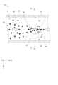
以下、図1および図2を参照し、第1実施形態の流体デバイス10について説明する。
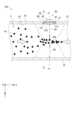
図1は、第1実施形態の流体デバイス10の一部を模式的に示す断面図であり、図2は、図1のA-A線矢視断面図である。
流体デバイス10は、内部に流路20が形成された流路基板30と、流路基板30に設けられた超音波発生部40とを備える。
この流体デバイス10では、超音波発生部40が、流路20を流通する流体Sに対して超音波を加えることで、流体Sの流通方向に直交する一方向に沿って、任意のモード次数の定在波SWを発生させる。流体S中に分散している微粒子Mは、流路20内を流通する過程で、定在波SWにより形成される圧力勾配の影響を受け、流路20内の所定範囲に収束する。
このような流体デバイス10では、例えば、流路20のうち、微粒子Mが収束される範囲の流体Sを選択的に流通させる濃縮用流路と、それ以外の範囲の流体Sを選択的に流通させる排出用流路とを設けることにより、流体Sにおける微粒子Mの濃度を濃縮することができる。[First embodiment]
Hereinafter, a
FIG. 1 is a cross-sectional view that diagrammatically shows a part of a
The
In this
In such a
なお、図1では、1次モードの定在波SWにより収束される微粒子Mの様子を模式的に例示している。また、図2では、微粒子Mの図示を省略し、流路20内に発生する定在波SWを圧力波形として示している。In addition, FIG. 1 shows a schematic example of the state of the particles M being converged by the first-mode standing wave SW. In addition, in FIG. 2, the particles M are not shown, and the standing wave SW generated in the
[流体デバイス10の構成]
図2を参照し、流体デバイス10の概略構成を説明する。
流路基板30は、内部に流路20が形成された基板である。この流路基板30は、例えば、流路20に対応する溝部を有する一対の基板を互いに接合することで作成できる。流路基板30を構成する各基板としては、特に限定されないが、例えばガラス基板やシリコン基板を利用できる。
なお、図示を省略するが、流路基板30には、流体Sを流路20に注入するための注入口と、流路20から流体Sを排出するための1以上の排出口とが設けられる。流路20が上述したような濃縮用流路および排出用流路にそれぞれ接続される場合には、これらの流路のそれぞれに排出口が設けられる。 [Configuration of fluid device 10]
The schematic configuration of the
The
Although not shown, the
本実施形態において、流路基板30に形成される流路20の断面は矩形であり、流路20の深さ方向は、流路基板30の厚み方向に一致する。また、流路20を流れる流体Sの流通方向は、流路20の深さ方向に直交し、流路20の幅方向は、流路20の深さ方向および流体Sの流通方向のそれぞれに直交する。
以下、流体Sの流通方向をX方向とし、流路20の幅方向をY方向とし、流路20の深さ方向をZ方向とする。X,Y,Z方向は、互いに直交する。 In this embodiment, the cross section of the
Hereinafter, the flow direction of the fluid S is defined as the X direction, the width direction of the
流路基板30は、Z方向の一方側において流路20の壁部を構成する上側壁部31と、Z方向の他方側において流路20の壁部を構成する下側壁部32と、Y方向の両側において流路20の壁部を構成する側方壁部33,34とを有する。
流路基板30には、上側壁部31をZ方向に貫通する貫通孔311が設けられている。 The
The
超音波発生部40は、流路基板30の貫通孔311を塞ぐように流路基板30に設けられる。これにより、超音波発生部40は、流路20の壁部の一部を成している。
具体的には、超音波発生部40は、素子基板41と、素子基板41に支持される振動膜42と、振動膜42に設けられる圧電素子43と、を備えている。
素子基板41は、Si等の半導体基板で構成される。この素子基板41は、流路基板30の貫通孔311内において、素子基板41の厚み方向がZ方向に沿うように配置されており、素子基板41の外周面は、流路基板30の貫通孔311の内周面に対して液密に接している。
また、素子基板41には、素子基板41の厚み方向に沿って素子基板41を貫通する開口部411が設けられている。 The ultrasonic
Specifically, the
The
The
振動膜42は、例えばSiO2膜およびZrO2膜など、複数種類の膜を積層した積層体等より構成されている。この振動膜42は、素子基板41に支持されると共に、開口部411の一方側(流路20側とは反対側)を閉塞する。
また、振動膜42のうち、素子基板41の厚み方向から見た際に開口部411と重なる部分は、超音波の送信を行う振動部421を構成する。振動部421が有する一対の面のうち一方の面は、流路20から開口部411内に流入する流体Sに接する流体接触面422となる。
ここで、振動膜42は、振動膜42の厚み方向(流体接触面422の法線方向)がZ方向に沿うように配置される。 The
In addition, a portion of the
Here, the
圧電素子43は、振動部421に対して流体接触面422とは反対側の面に設けられている。この圧電素子43は、図示を省略するが、振動部421上に下部電極、圧電膜および上部電極が順に積層されることにより構成されている。The
このような超音波発生部40では、振動部421と当該振動部421上に配置された圧電素子43とにより、超音波素子44が構成される。
この超音波素子44では、圧電素子43が図示を省略する駆動部に接続されており、この駆動部から圧電素子43に駆動信号が入力されると、下部電極と上部電極との間に電圧が印加され、圧電膜が伸縮する。これにより、振動部421は、振動部421の短辺方向の寸法W(開口部411の開口幅)などに応じた所定の発振周波数で、流体接触面422の法線方向に撓み振動する。振動部421の撓み振動は、流体Sの粗密波に変換されることで超音波の伝搬が行われる。流体Sに伝搬された超音波は、振動部421を中心に放射状に拡散され、このうちY方向に向かって進む超音波が、流路20の内壁で反射を繰り返すことで、流路20内に定在波SWを発生させる。 In such an
In this
ここで、流路20内において、Y方向に定在波SWを発生させるため、流路20のY方向の寸法である流路幅L[m]は、以下の式(1)を満たす。
上記式(1)によれば、仮に、媒質が水である場合の媒質の音速Cを1500m/sとし、定在波SWのモード次数nを1とし、圧電素子43の駆動周波数Fを600kHzとする場合、流路幅Lは、1.25mmに設定される。According to the above formula (1), if the sound speed C of the medium is 1500 m/s when the medium is water, the mode order n of the standing wave SW is 1, and the driving frequency F of the
また、流路20内において、Z方向の定在波が発生することを抑えるため、流路20のZ方向の寸法である流路深さH[m]は、以下の式(2)を満たす。
あるいは、流路20内において、Z方向の定在波が発生することを抑えるため、流路深さHは、上記式(2)を満たさずに、上記式(1)により設定された流路幅Lよりも著しく大きく設定されてもよい。この場合、Z方向に高次モードの定在波が発生する可能性があるが、このような高次モードの定在波は、Y方向発生する定在波SWと比較して音響パワーが小さくなるため、その影響を無視することができる。Alternatively, in order to suppress the generation of standing waves in the Z direction within the
[振動部421の厚み]
圧電素子43が駆動される際、振動部421に撓み振動を生じさせる横波だけでなく、振動部421の内部を伝搬される縦波が発生する。
仮に、振動部421の厚みtが、縦波の波長λよりも大きい場合、振動部421内に縦波が支配的になり、振動部421から流体Sへの超音波の伝搬効率が低下してしまう。すなわち、音響インピーダンスのマッチングが取れていない状態と等しくなってしまう。
また、仮に、振動部421の厚みtが縦波の波長λよりも小さい場合であっても、縦波は振動膜42内に若干ながら発生する。特に、振動部421の厚みtがλ/4と等しい場合には、振動部421が縦波の音響整合層として機能し、振動部421内で発生する縦波が流体Sへ伝搬され易くなるが、縦波での音響射出の場合、横波での音響射出の場合と比較して、振動部421から流体Sへの超音波の伝搬効率が低下してしまう。 [Thickness of vibration part 421]
When the
If the thickness t of the
Furthermore, even if the thickness t of the
そこで、本実施形態において、振動部421は、厚みtが縦波の波長λの1/4よりも小さくなるように形成される。すなわち、振動部421の厚みt[m]は、以下の式(3)を満たす。
上記式(3)における縦波の波長λ[m]は、以下の式(4)で表される。
上記式(4)によれば、上記式(3)は、以下の式(5)で表される。
According to the above formula (4), the above formula (3) is expressed by the following formula (5).
また、上記式(5)における駆動周波数Fは、上述したように、以下の式(1)を満たす。
上記式(1)、(5)によれば、振動部421の厚みtは、以下の式(6)を満たす。
According to the above formulas (1) and (5), the thickness t of the
また、本実施形態の振動膜42は、複数の膜の積層体である。すなわち、本実施形態の振動部421は、複数の膜により構成される。この場合、振動部421に発生する縦波の平均音速C’は、以下の方法により算出される。
ここで、振動部421を構成する膜の数をmとし、振動部421を構成する各膜の厚みをtk(k=1,2,・・・m)とし、振動部421を構成する各膜における縦波音速の平均をCk(k=1,2,・・・m)とする場合、以下の式(7)が成り立つ。
Here, if the number of films constituting the vibrating
また、振動部421の厚みtは、以下の式(8)により表される。

また、振動部421の厚みtは、振動部421から流体Sへの超音波の伝搬効率を向上させる観点から考えると、上記式(6)を満たしつつ、より小さい値であることが望ましい。
ただし、振動部421の厚みtが小さくなり過ぎると、振動部421の厚み方向への応力勾配が大きくなるため、圧電素子43が駆動される際、振動部421に破損が生じる可能性が高くなる。
そこで、本実施形態では、振動部421の短辺方向の寸法Wと振動部421の厚みtを変化させて圧電素子43を駆動させる実験を行った結果、振動部421の厚みtが、以下の式(10)を満たすことが好ましい。
However, if the thickness t of the
Therefore, in this embodiment,an experiment was conducted in which the short side dimension W of the
なお、上述したように、本実施形態の振動部421は、複数(m枚)の膜により構成される。この場合、振動部421の平均ヤング率E’は、以下の式(11)により表すことができる。

上記式(11),(12)において、mは、振動部421を構成する膜の数であり、Ei(i=1、2、・・・m)は、ポアソン比を0.3としたときの振動部421を構成する各膜のヤング率である。
また、diは、以下の式(13)によって表わされる。
Moreover, di is expressed by the following equation (13).
ここで、仮に、本実施形態の流体デバイス10が以下に記載の構成を有する場合、上述した式(6)および式(10)により、振動部421の厚みtは、以下の式(14)の範囲であることが好ましい。
振動部の短片方向の寸法W:19μm
流路幅L:375μm
流体Sの媒質の音速C:1500m/s
定在波SWのモード次数n:1
振動膜42:SiO2膜とZrO2膜との2層構造
SiO2膜の膜厚t1:0.35μm
ZrO2膜の膜厚t2:0.15μm
SiO2のヤング率E1:75GPa
ZrO2のヤング率E2:190GPa
SiO2の音速C1:5900m/s
ZrO2の音速C2:4650m/s
Dimension W of the vibrating part in the short side direction: 19 μm
Flow path width L: 375 μm
Speed of sound C of fluid S: 1500 m/s
Standing wave SW mode number n: 1
Vibration membrane 42: Two-layer structure ofSiO2 film andZrO2 filmSiO2 film thickness t1: 0.35 μm
Thickness t2 ofZrO2 film: 0.15 μm
Young's modulusE1 ofSiO2 : 75 GPa
Young's modulusE2 ofZrO2 : 190 GPa
Sound speedC1 ofSiO2 : 5900 m/s
Sound speedC2 ofZrO2 : 4650 m/s
[超音波素子44の配置]
流路20の内部にY方向の定在波SWが生じた場合、音圧が最大になる腹Aと、音圧が0になる節NとがY方向に沿って周期的に現れる。なお、本実施形態では、流路20のY方向の両端部のそれぞれに腹Aが現れる。
例えば、図2に示すように、1次モードの定在波SWが生じた場合、流路20のY方向中央部に節Nが現れ、流路20のY方向両端部のそれぞれに腹Aが現れる。この場合、流体S中に分散している微粒子Mは、流路20内を流通する過程で、定在波SWの節Nに対応する範囲、すなわち流路20のY方向中央部へ収束する(音響収束)。 [Arrangement of ultrasonic element 44]
When a standing wave SW in the Y direction occurs inside the
2, when a first-order mode standing wave SW occurs, a node N appears in the center of the
ここで、流路20は、Y方向において、定在波SWの節Nに対応する節領域RNと、定在波SWの腹Aに対応する腹領域RAとに、領域分けされる。
なお、流路20の流路幅をL、定在波SWのモード次数をnとするとき、各節領域RNは、各節Nの中心からY方向に±L/4nまでの範囲とし、各腹領域RAは、それ以外の範囲とする。
このように領域分けされる流路20に対し、超音波素子44、具体的には振動部421の流体接触面422は、Z方向において任意の腹領域RAに対向するように配置される。換言すると、素子基板41の開口部411は、腹領域RAに向かって開口する。
また、超音波素子44の大きさによっては、超音波素子44が腹領域RAだけでなく、節領域RNにはみ出して存在してもよいが、振動部421が節Nには対向配置されないことが望ましい。
なお、図2は、1次モードの定在波SWを例示しているが、本実施形態で発生させる定在波SWは、1次モード以上であればよい。 Here, the
In addition, when the flow path width of the
For the
Depending on the size of the
Although FIG. 2 illustrates a first mode standing wave SW, the standing wave SW generated in this embodiment may be of a first mode or higher.
[本実施形態の効果]
以上に説明したように、本実施形態の流体デバイス10は、流体Sが流通する流路20と、流体Sに超音波を送信することで、流路20内の流体Sに、流体Sの流通方向に直交する第1方向(Y方向)に沿って定在波SWを発生させる超音波素子44と、を備える。超音波素子44は、流体Sに接する流体接触面422を有する振動部421と、振動部421に設けられ、振動部421を流体接触面422の法線方向に撓み振動させる圧電素子43と、を有する。そして、振動部421の厚み[m]をtとし、流体Sの媒質の音速[m/s]をCとし、振動部421の縦波音速[m/s]をC’とし、Y方向における流路20の寸法[m]をLとし、定在波SWのモード次数をnとするとき、流体デバイス10は、以下の式(6)を満たすように構成される。
As described above, the
このような構成では、振動部421の流体接触面422が流体Sに接触するため、超音波素子44から流体Sまでの超音波の伝搬経路に流路基板30が介在しない。すなわち、超音波素子44から流体Sへ超音波がダイレクトに伝達される。
また、流体Sに接触する振動部421の厚みが上記式(6)の範囲で形成されることにより、振動部421内での縦波の発生や振動部421から流体Sへの縦波の伝搬が抑制される。
以上の構成によれば、超音波素子44の振動部421と、振動部421に接する流体Sとの間の音響インピーダンスのマッチングが取れたことに等しい状態になり、超音波素子44から流体Sへの超音波の伝搬効率を向上させることができる。これにより、圧電素子43に加える駆動電圧および駆動周波数を従来よりも低く設定することができると共に、定在波SWを発生させる流路20の幅を従来よりも広く構成することができる。その結果、流体デバイス10を用いて処理できる流体Sの体積流量を大量化することができる。 In this configuration, the
Furthermore, by forming the thickness of the
According to the above configuration, it is possible to achieve a state equivalent to matching of acoustic impedance between the
また、本実施形態の流体デバイス10は、振動部421の短辺方向の寸法[m]をWとし、ポアソン比を0.3としたときの前記振動膜の平均ヤング率[Pa]をE’とし、前記流体の媒質の音速[m/sec]をCとするとき、以下の式(10)を満たすように構成される。
また、本実施形態の流体デバイス10において、振動部421は、定在波SWにおける任意の腹Aに対応する腹領域RAに対向するように配置される。
このような配置によれば、超音波素子44から流体Sへの超音波の伝搬効率をより向上させることができる。 Furthermore, in the
With such an arrangement, the efficiency of ultrasonic propagation from the
また、本実施形態の流体デバイス10において、Z方向(流通方向および第1方向のそれぞれに直交する第2方向)における流路20の寸法(流路深さ)Hは、Y方向における流路20の寸法(流路幅)よりも小さい。
これにより、Z方向に定在波が発生することを抑え、Y方向の定在波SWを好適に発生させることができる。 Furthermore, in the
This makes it possible to suppress the generation of standing waves in the Z direction and to favorably generate standing waves SW in the Y direction.
[第2実施形態]
次に、第2実施形態について説明する。
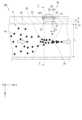
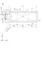
図3は、第2実施形態の流体デバイス10Aの一部を模式的に示す断面図であり、図4は、図3のB-B線矢視断面図である。
第2実施形態の流体デバイス10Aは、流路基板30に対する超音波発生部40の配置以外、第1実施形態の流体デバイス10とほぼ同様の構成を有する。
以下では、第1実施形態と同様の構成には同一符号を付し、その説明を省略または簡略化する。[Second embodiment]
Next, a second embodiment will be described.
FIG. 3 is a cross-sectional view that diagrammatically shows a part of a
The
In the following, the same components as those in the first embodiment are denoted by the same reference numerals, and the description thereof will be omitted or simplified.
第2実施形態において、流路基板30には、側方壁部33をY方向に貫通する貫通孔331が設けられている。
超音波発生部40は、側方壁部33の貫通孔331を塞ぐように流路基板30に設けられることにより、流路20の壁部の一部を成す。超音波素子44は、振動部421の厚み方向がY方向に沿うように配置され、振動部421は、Y方向において流路20の腹領域RAに対向する。 In the second embodiment, the
The
[第2実施形態の効果]
以上の第2実施形態によれば、第1実施形態の流体デバイス10と同様の効果を奏することができる。
また、第2実施形態において、超音波素子44は、振動部421の厚み方向がY方向に沿うように配置されるため、超音波素子44からの超音波の主な送信方向と、流路20内で定在波SWを合成する超音波の伝搬方向とが一致する。これにより、定在波SWの形成効率をより向上させることができる。[Effects of the second embodiment]
According to the second embodiment described above, it is possible to achieve the same effects as those of the
In the second embodiment, the
[第3実施形態]
次に、第3実施形態について説明する。
図5は、第3実施形態の流体デバイス10Bの一部を模式的に示す断面図であり、図6は、図5のC-C線矢視断面図である。
第3実施形態の流体デバイス10Bは、超音波発生部40と流路20との間に圧力室51および連通路52が介在する以外、第2実施形態の流体デバイス10とほぼ同様の構成を有する。
以下では、第1,第2実施形態と同様の構成には同一符号を付し、その説明を省略または簡略化する。[Third embodiment]
Next, a third embodiment will be described.
FIG. 5 is a cross-sectional view that diagrammatically shows a part of a
The
In the following, the same components as those in the first and second embodiments are denoted by the same reference numerals, and the description thereof will be omitted or simplified.
圧力室51は、流路基板30内に形成された流体Sの貯留室であり、Y方向において流路20との間に間隔を空けて形成されている。本実施形態では、圧力室51は、流路20のY方向一方側の側方壁部33に形成されているが、Y方向他方側の側方壁部34に形成されてもよい。
連通路52は、流路基板30の側方壁部33の内部に形成され、圧力室51と流路20とを連通する流路である。連通路52は、Y方向に沿って形成され、流路20の側部に接続されている。
流路20は、連通路52を介して圧力室51に接続されており、流路20を流通する流体Sは、圧力室51内に流入する。圧力室51内は、流体Sにより満たされる。
なお、図5および図6では、2つの連通路52が設けられており、各連通路52が圧力室51と流路20とを連通している。ただし、連通路52の数は、2つに限られず、1つ以上であればよい。 The
The
The
5 and 6, two
流路基板30の側方壁部33のうち、圧力室51の壁部となる部分には、圧力室51と外部とをY方向に繋げる貫通孔332が設けられている。超音波送信部40は、この貫通孔332を塞ぐように流路基板30に設けられることにより、圧力室51の壁部の一部を成す。素子基板41は、流路基板30の貫通孔332内において、素子基板41の厚み方向がY方向に沿うように配置され、素子基板41の外周面は、流路基板30の貫通孔332の内周面に対して液密に接している。
ここで、超音波素子44は、振動部421の厚み方向がY方向に沿うように配置され、振動部421は、圧力室51および連通路52を介して、Y方向に流路20の腹領域RAに対向する。振動部421の流体接触面422は、圧力室51内の流体Sに接する。 A through hole 332 that connects the
Here, the
また、第3実施形態の流体デバイス10Bは、連通路52内および圧力室51内の流体Sに定在波を生じさせずに、流路20内の流体Sに定在波を生じさせるため、以下の式(15)を満たすように構成される。
また、第3実施形態の流体デバイス10Bは、以下の式(16)~(18)を満たすように構成される。
上記式(16),(17)が満たされる場合、連通路52から流路20内に照射された超音波が流路20の壁面で反射されて連通路52に戻ってきたとき、超音波のビーム幅が連通路52の幅Wrよりも大きくなる。すなわち、超音波のビーム幅が連通路52の幅Wrよりも大きく広がった状態になる。
また、上記の式(18)において、Srは、全ての連通路52のY方向に直交する流路断面積[m2]であり、Lは、流路幅[m]であり、nは、定在波SWのモード次数であり、Sbは、振動部421の流体接触面422の面積[m2]であり、δは、振動時における振動部421の変位量[m]である。
上記式(18)が満たされる場合、連通路52がY方向に面する流路20内の範囲の体積を定在波SWのモード次数nで割った値が、振動部421の撓み振動によって生じる圧力室51の体積の最大変動量以上になる。 Moreover, the
When the above formulas (16) and (17) are satisfied, when the ultrasonic wave irradiated from the
In addition, in the above equation (18), Sr is the flow path cross-sectional area [m2 ] of all connecting
When the above formula (18) is satisfied, the value obtained by dividing the volume of the area within the
[第3実施形態の効果]
以上の第3実施形態によれば、第1実施形態の流体デバイス10と同様の効果および第2実施形態の流体デバイス10Aと同様の効果を奏することができる。[Effects of the third embodiment]
According to the third embodiment described above, it is possible to achieve the same effects as the
ここで、第1~第3実施形態では、振動部421が流体Sに面しているため、超音波素子44は、流体Sに対して超音波をダイレクトに送信する。流体S内を伝達される超音波は、音響パワーがほぼ減衰しないまま、流路20の壁面で反射されることで定在波SWを形成する。
上述の第1実施形態および第2実施形態では、振動部421が流路20内の流体Sに面しているため、流路20内で反射された超音波が振動部421までダイレクトに帰ってくる。このため、超音波素子44は、当初に加えた音響パワー以上の超音波を送信しない限り、反射されて帰ってくる超音波に撃ち負けてしまい、流路20内の超音波の音響パワーを重畳させることが困難である。すなわち、流路20内の超音波の音響パワーは、最初に送信された超音波の音響パワーによって決定されてしまい、音響パワーの継ぎ足しが困難である。
これに対して、第3実施形態の流体デバイス10Bは、流体Sを貯留する圧力室51と、Y方向に沿って形成されて流路20と圧力室51とを連通する連通路52と、をさらに備え、超音波素子44は、振動部421の流体接触面422が圧力室51内の流体Sに接するように配置される。
このような第3実施形態によれば、流路20の壁面で反射された超音波の一部は、連通路52を介して振動部421にまで帰ってくるが、当該超音波の残りの部分は、流路20の壁面で再度反射する。すなわち、振動部421に帰ってくる超音波の割合を抑制できる。このため、超音波素子44が送信する超音波は、連通路52を介して振動部421に帰ってくる超音波に撃ち負けず、圧力室51内の圧力を高めることで、流路20内に音響パワーを継ぎ足すことができる。これにより、より高い音響パワーの定在波SWを発生させることが容易になる。
特に、第3実施形態の流体デバイス10Bは、上記式(16),(17)を満たすように構成されることで、超音波のビーム幅が連通路52の幅Wrよりも大きく広がった状態になるため、振動部421に帰ってくる超音波の割合を抑制する効果を好適に発揮することができる。 Here, in the first to third embodiments, since the
In the above-described first and second embodiments, since the
In contrast, the
According to the third embodiment, a portion of the ultrasonic waves reflected by the wall surface of the
In particular, the
さらに、第3実施形態において、流体デバイス10Bは、上記式(18)が成り立つように構成される。ここで、連通路52がY方向に面する流路20内の範囲の体積を定在波SWのモード次数nで割った値は、連通路52内の媒質の体積変動に相当する。当該値が振動部421の撓み振動によって生じる圧力室51の体積の最大変動量以上になることで、振動膜42の変形による圧力室51内の媒質の体積変動は、連通路52内の媒質の体積変動として排出されるため、圧力室51内の圧力上昇を抑えることが可能になる。よって、振動膜42や圧電素子43が破損することを抑制できる。Furthermore, in the third embodiment, the
[変形例]
なお、本発明は上述の各実施形態に限定されるものではなく、本発明の目的を達成できる範囲での変形、改良、および各実施形態を適宜組み合わせる等によって得られる構成は本発明に含まれるものである。[Modification]
The present invention is not limited to the above-described embodiments, and the present invention includes configurations obtained by modifying, improving, and appropriately combining the embodiments within the scope that can achieve the object of the present invention.
(変形例1)
上記各実施形態では、流体デバイス10,10A,10Bにおいて、1個の超音波素子44が設けられる例を示しているが、複数の超音波素子44が設けられてもよい。
例えば、素子基板41に対して複数の開口部411がアレイ状に設けられ、素子基板41に設けられる振動膜42のうちの各開口部411に重なる部分が、振動部421を構成してもよい。この場合、各振動部421に対して圧電素子43が設けられることで、複数の超音波素子44が構成される。
また、上記各実施形態で説明したような超音波発生部40が複数設けられてもよい。
なお、上記第3実施形態において、複数の超音波素子44が設けられた場合、上記式(18)におけるSbは、複数の超音波素子44の流体接触面422の合計面積である。 (Variation 1)
In each of the above embodiments, an example in which one
For example, a plurality of
Furthermore, a plurality of
In the above third embodiment, when a plurality of
(変形例2)
上記第1実施形態および上記第2実施形態では、流路20内に形成される定在波SWのうち1つの腹領域RAに対して超音波素子44が配置される例を示しているが、2以上の腹領域RAに対して、それぞれ超音波素子44が配置されてもよい。
ただし、定在波SWの節Nの両側に現れる腹Aでは、圧力波形の位相が互いに逆になる。
このため、一方の腹Aに対応する腹領域RAに対して配置される超音波素子44と、他方の腹Aに対応する腹領域RAに対して配置される超音波素子44との間では、駆動周波数の位相を逆にすることが望ましい。 (Variation 2)
In the above first and second embodiments, an example is shown in which an
However, at antinodes A appearing on both sides of a node N of the standing wave SW, the phases of the pressure waveform are opposite to each other.
For this reason, it is desirable to reverse the phase of the drive frequency between the
(変形例3)
上記第3実施形態において、超音波素子44は、振動部421の厚み方向がY方向に沿うように配置されているが、これに限られない。
例えば、上記第3実施形態では、圧力室51の壁部となる流路基板30の部分にZ方向の貫通孔が設けられ、超音波発生部40は、当該貫通孔を塞ぐように設けられ、超音波素子44は、振動部421の厚み方向がZ方向に沿うように配置されてもよい。
この場合、超音波素子44から送信される超音波のうち、Z方向に対して角度を有する成分が連通路52を介して流路20に向かい、流路20の内壁で反射を繰り返すことにより、流路20内にY方向の定在波SWが発生する。 (Variation 3)
In the third embodiment, the
For example, in the above third embodiment, a Z-direction through hole is provided in a portion of the
In this case, of the ultrasonic waves transmitted from the
(変形例4)
上記各実施形態で説明した超音波発生部40の具体的構成は、様々な変形が可能である。
例えば、素子基板41は、流路基板30の貫通孔311の外側に配置されてもよい。この場合、素子基板41の開口部411が流路基板30の貫通孔311に重なるように配置され、素子基板41の下面が流路基板30の上面に対して液密に接着される。
また、超音波発生部40は、素子基板41を備えず、振動膜42は、流路基板30に設けられてもよい。この場合、振動膜42のうち流路基板30の貫通孔311,331に重なる部分が振動部421を構成する。 (Variation 4)
The specific configuration of the
For example, the
Moreover, the
(変形例5)
上記各実施形態では、流体Sの流通方向に直交する一方向として、流路20の幅方向(Y方向)に定在波SWを発生させるが、流路20の深さ(Z方向)に定在波SWを発生させてもよい。この場合、上記各実施形態で説明したY方向とZ方向とを適宜置き換えた構成が可能である。 (Variation 5)
In each of the above embodiments, the standing wave SW is generated in the width direction (Y direction) of the
[本開示のまとめ]
本開示の一態様に係る超音波デバイスは、流体が流通する流路と、前記流体に超音波を送信することで、前記流路内の前記流体に、前記流体の流通方向に直交する第1方向に沿って定在波を発生させる超音波素子と、を備え、前記超音波素子は、前記流体に接する流体接触面を有する振動部と、前記振動部に設けられ、前記振動部を前記流体接触面の法線方向に撓み振動させる圧電素子と、を有し、前記法線方向における前記振動部の厚みをtとし、前記流体の媒質の音速をCとし、前記振動部内を伝達する縦波の平均音速をC’とし、前記第1方向における前記流路の寸法をLとし、前記定在波のモード次数をnとするとき、
An ultrasonic device according to one aspect of the present disclosure includes a flow path through which a fluid flows, and an ultrasonic element that generates a standing wave in the fluid in the flow path along a first direction perpendicular to a flow direction of the fluid by transmitting ultrasonic waves to the fluid, the ultrasonic element having a vibration part having a fluid contact surface that contacts the fluid, and a piezoelectric element provided on the vibration part that flexes and vibrates the vibration part in a normal direction to the fluid contact surface, and when a thickness of the vibration part in the normal direction is t, a sound speed of the medium of the fluid is C, an average sound speed of longitudinal waves propagating within the vibration part is C', a dimension of the flow path in the first direction is L, and a mode order of the standing wave is n,
このような構成では、振動部の流体接触面が流体に接触するため、超音波素子から流体までの超音波の伝搬経路に他の部材が介在しない。すなわち、超音波素子から流体へ超音波がダイレクトに伝達される。
また、流体に接触する振動部の厚みが上記式の範囲で形成されることにより、振動部内での縦波の発生や振動部から流体への縦波の伝搬が抑制される。
以上の構成によれば、超音波素子の振動部と、振動部に接する流体との間の音響インピーダンスのマッチングが取れたことに等しい状態になり、超音波素子から流体への超音波の伝搬効率を向上させることができる。これにより、圧電素子に加えられる駆動電圧および駆動周波数を従来よりも低く設定することができると共に、定在波を発生させる流路の幅を従来よりも広く構成することができる。その結果、流体デバイスを用いて処理できる流体の体積流量を大量化させることができる。 In this configuration, the fluid contact surface of the vibration unit is in contact with the fluid, so that no other members are interposed in the propagation path of the ultrasonic waves from the ultrasonic element to the fluid, i.e., the ultrasonic waves are transmitted directly from the ultrasonic element to the fluid.
Furthermore, by forming the thickness of the vibration part that comes into contact with the fluid within the range of the above formula, the generation of longitudinal waves within the vibration part and the propagation of longitudinal waves from the vibration part to the fluid are suppressed.
According to the above configuration, the acoustic impedance between the vibration part of the ultrasonic element and the fluid in contact with the vibration part is matched, and the efficiency of ultrasonic wave propagation from the ultrasonic element to the fluid can be improved. As a result, the driving voltage and driving frequency applied to the piezoelectric element can be set lower than before, and the width of the flow path that generates the standing wave can be configured wider than before. As a result, the volume flow rate of the fluid that can be processed using the fluid device can be increased.
本態様に係る流体デバイスにおいて、前記振動部の前記法線方向に直交する短辺方向の寸法をWとし、ポアソン比を0.3としたときの前記振動部の平均ヤング率をE’とし、前記流体の媒質の音速をCとするとき、
このような構成によれば、振動部をできるだけ薄く形成することで超音波素子から流体への超音波の伝搬効率を向上させつつ、圧電素子が駆動される際における振動部の破損を抑制できる。 In the fluidic device according to this aspect, when the dimension of the vibration part in the short side direction perpendicular to the normal direction is W, the average Young's modulus of the vibration part when the Poisson's ratio is 0.3 is E', and the sound speed of the fluid medium is C,
According to such a configuration, by forming the vibration portion as thin as possible, it is possible to improve the efficiency of propagation of ultrasonic waves from the ultrasonic element to the fluid, while suppressing damage to the vibration portion when the piezoelectric element is driven.
本態様に係る流体デバイスにおいて、前記振動部は、前記定在波における任意の腹に対応する腹領域に対向するように配置される。
このような配置によれば、超音波素子から流体への超音波の伝搬効率をより向上させることができる。 In the fluidic device according to this aspect, the vibration portion is disposed so as to face an antinode region corresponding to any antinode in the standing wave.
With this arrangement, the efficiency of ultrasonic wave propagation from the ultrasonic element to the fluid can be further improved.
本態様に係る流体デバイスにおいて、前記振動部は、前記振動部の厚み方向が前記第1方向に沿うように配置される。
これにより、超音波素子からの超音波の主な送信方向と、流路内に定在波を合成する超音波の伝搬方向とが一致するため、定在波の形成効率をより向上させることができる。 In the fluidic device according to this aspect, the vibration section is disposed such that the thickness direction of the vibration section is aligned with the first direction.
This causes the main transmission direction of the ultrasonic waves from the ultrasonic element to coincide with the propagation direction of the ultrasonic waves that synthesize standing waves within the flow channel, thereby further improving the efficiency of forming standing waves.
本態様に係る流体デバイスにおいて、前記流通方向および前記第1方向のそれぞれに対して直交する第2方向における前記流路の寸法は、前記第1方向における前記流路の寸法よりも小さい。
これにより、第2方向に定在波が発生することを抑え、第1方向の定在波を好適に発生させることができる。 In the fluidic device according to this aspect, the dimension of the flow channel in a second direction perpendicular to both the flow direction and the first direction is smaller than the dimension of the flow channel in the first direction.
This makes it possible to suppress the occurrence of standing waves in the second direction and to favorably generate standing waves in the first direction.
本態様に係る流体デバイスにおいて、前記流体を貯留する圧力室と、前記第1方向に沿って形成され、前記流路と前記圧力室とを連通する連通路と、をさらに備え、前記超音波素子は、前記流体接触面が前記圧力室内の前記流体に接するように配置される。
このような構成によれば、超音波素子が送信する超音波は、流路内で反射されて連通路を介して振動部に帰ってくる超音波に撃ち負けず、圧力室内の圧力を高めることで、流路内に音響パワーを継ぎ足すことができる。これにより、より高い音響パワーの定在波を発生させることが容易になる。 The fluidic device of this aspect further comprises a pressure chamber for storing the fluid, and a communication passage formed along the first direction and connecting the flow path and the pressure chamber, and the ultrasonic element is positioned so that the fluid contact surface is in contact with the fluid in the pressure chamber.
With this configuration, the ultrasonic waves transmitted by the ultrasonic element are not defeated by the ultrasonic waves reflected in the flow path and returning to the vibration part through the communication path, and by increasing the pressure in the pressure chamber, acoustic power can be added to the flow path. This makes it easy to generate standing waves with higher acoustic power.
10,10A,10B…流体デバイス、20…流路、30…流路基板、31…上側壁部、311…貫通孔、32…下側壁部、33…側方壁部、331…貫通孔、34…側方壁部、40…超音波発生部、41…素子基板、411…開口部、42…振動膜、421…振動部、422…流体接触面、43…圧電素子、44…超音波素子、51…圧力室、52…連通路、H…流路深さ、L…流路幅、M…微粒子、N…節、A…腹、RA…腹領域、RN…節領域、S…流体、SW…定在波、t…振動部の厚み、W…振動部の短辺方向の寸法。10, 10A, 10B...fluid device, 20...flow path, 30...flow path substrate, 31...upper wall, 311...through hole, 32...lower wall, 33...side wall, 331...through hole, 34...side wall, 40...ultrasonic generator, 41...element substrate, 411...opening, 42...vibration membrane, 421...vibration portion, 422...fluid contact surface, 43...piezoelectric element, 44...ultrasonic element, 51...pressure chamber, 52...connection path, H...flow path depth, L...flow path width, M...particle, N...node, A...antinode, RA...antinode region, RN...node region, S...fluid, SW...standing wave, t...thickness of vibration portion, W...dimension of vibration portion in the short side direction.
Claims (6)
Translated fromJapanese前記流体に超音波を送信することで、前記流路内の前記流体に、前記流体の流通方向に直交する第1方向に沿って定在波を発生させる超音波素子と、を備え、
前記超音波素子は、
前記流体に接する流体接触面を有する振動部と、
前記振動部に設けられ、前記振動部を前記流体接触面の法線方向に撓み振動させる圧電素子と、を有し、
前記法線方向における前記振動部の厚みをtとし、前記流体の媒質の音速をCとし、前記振動部内を伝達する縦波の平均音速をC’とし、前記第1方向における前記流路の寸法をLとし、前記定在波のモード次数をnとするとき、

an ultrasonic element that generates a standing wave in the fluid in the flow channel along a first direction perpendicular to a flow direction of the fluid by transmitting an ultrasonic wave to the fluid;
The ultrasonic element is
a vibration section having a fluid contact surface that contacts the fluid;
a piezoelectric element provided in the vibration portion to deflect and vibrate the vibration portion in a normal direction to the fluid contact surface,
When the thickness of the vibration part in the normal direction is t, the sound speed of the fluid medium is C, the average sound speed of the longitudinal wave propagating in the vibration part is C', the dimension of the flow path in the first direction is L, and the mode order of the standing wave is n,
前記振動部の前記法線方向に直交する短辺方向の寸法をWとし、ポアソン比を0.3としたときの前記振動部の平均ヤング率をE’とし、前記流体の媒質の音速をCとするとき、

When the dimension of the vibration part in the short side direction perpendicular to the normal direction is W, the average Young's modulus of the vibration part when the Poisson's ratio is 0.3 is E', and the sound speed of the fluid medium is C,
前記振動部は、前記定在波における任意の腹に対応する腹領域に対向するように配置される
ことを特徴とする流体デバイス。 The fluidic device according to claim 1 or 2,
The fluid device, wherein the vibrating portion is disposed so as to face an antinode region corresponding to any antinode in the standing wave.
前記振動部は、前記流体接触面の前記法線方向が前記第1方向に沿うように配置される
ことを特徴とする流体デバイス。 The fluidic device according to any one of claims 1 to 3,
The fluid device, wherein the vibration portion is disposed such that the normal direction of the fluid contact surface is aligned with the first direction.
前記流通方向および前記第1方向のそれぞれに対して直交する第2方向における前記流路の寸法は、前記第1方向における前記流路の寸法よりも小さい
ことを特徴とする流体デバイス。 The fluidic device according to any one of claims 1 to 4,
A fluidic device, characterized in that a dimension of the flow channel in a second direction perpendicular to both the flow direction and the first direction is smaller than a dimension of the flow channel in the first direction.
前記流体を貯留する圧力室と、
前記第1方向に沿って形成され、前記流路と前記圧力室とを連通する連通路と、をさらに備え、
前記超音波素子は、前記流体接触面が前記圧力室内の前記流体に接するように配置される
ことを特徴とする流体デバイス。 The fluidic device according to any one of claims 1 to 5,
A pressure chamber that stores the fluid;
a communication passage formed along the first direction and communicating between the flow path and the pressure chamber,
A fluidic device, characterized in that the ultrasonic element is arranged so that the fluid contact surface is in contact with the fluid in the pressure chamber.
Priority Applications (3)
| Application Number | Priority Date | Filing Date | Title |
|---|---|---|---|
| JP2020129407AJP7484534B2 (en) | 2020-07-30 | 2020-07-30 | Fluid Devices |
| CN202110857422.0ACN114076621B (en) | 2020-07-30 | 2021-07-28 | Fluid device |
| US17/388,585US12392751B2 (en) | 2020-07-30 | 2021-07-29 | Fluid device |
Applications Claiming Priority (1)
| Application Number | Priority Date | Filing Date | Title |
|---|---|---|---|
| JP2020129407AJP7484534B2 (en) | 2020-07-30 | 2020-07-30 | Fluid Devices |
Publications (2)
| Publication Number | Publication Date |
|---|---|
| JP2022026105A JP2022026105A (en) | 2022-02-10 |
| JP7484534B2true JP7484534B2 (en) | 2024-05-16 |
Family
ID=80004199
Family Applications (1)
| Application Number | Title | Priority Date | Filing Date |
|---|---|---|---|
| JP2020129407AActiveJP7484534B2 (en) | 2020-07-30 | 2020-07-30 | Fluid Devices |
Country Status (3)
| Country | Link |
|---|---|
| US (1) | US12392751B2 (en) |
| JP (1) | JP7484534B2 (en) |
| CN (1) | CN114076621B (en) |
Citations (8)
| Publication number | Priority date | Publication date | Assignee | Title |
|---|---|---|---|---|
| JP2000296374A (en) | 1999-04-14 | 2000-10-24 | Kaijo Corp | Ultrasonic excitation device and ultrasonic cleaning device having the same |
| JP2001526108A (en) | 1997-12-19 | 2001-12-18 | ビーエーエスエフ アクチェンゲゼルシャフト | Apparatus for producing dispersed mixtures using ultrasound and methods of using the same |
| JP2002339872A (en) | 2001-05-17 | 2002-11-27 | Matsushita Electric Ind Co Ltd | Method and apparatus for driving piezoelectric pump |
| JP2002345915A (en) | 2001-05-28 | 2002-12-03 | Matsushita Electric Works Ltd | Ultrasonic instrument for cosmetic |
| WO2007013287A1 (en) | 2005-07-27 | 2007-02-01 | Kyushu Institute Of Technology | Valveless micropump |
| JP2007283278A (en) | 2006-04-12 | 2007-11-01 | Kiyasu Ishida | Underwater ultrasonic oscillator |
| US20190191252A1 (en) | 2017-12-14 | 2019-06-20 | Flodesign Sonics, Inc. | Acoustic transducer driver and controller |
| US20190342654A1 (en) | 2018-05-02 | 2019-11-07 | Ultrahaptics Limited | Blocking Plate Structure for Improved Acoustic Transmission Efficiency |
Family Cites Families (15)
| Publication number | Priority date | Publication date | Assignee | Title |
|---|---|---|---|---|
| US5295487A (en)* | 1992-02-12 | 1994-03-22 | Kabushiki Kaisha Toshiba | Ultrasonic probe |
| CN1104629C (en)* | 1995-12-13 | 2003-04-02 | 松下电器产业株式会社 | Ultrasonic flowmeter and ultrasonic generator/detector |
| JP3343030B2 (en)* | 1996-05-22 | 2002-11-11 | 日本碍子株式会社 | Sensor element |
| JP3233041B2 (en)* | 1996-08-13 | 2001-11-26 | 株式会社村田製作所 | Piezoelectric acoustic transducer |
| JP2001304931A (en)* | 2000-04-26 | 2001-10-31 | Yokogawa Electric Corp | Clamp-on type ultrasonic flow rate measuring method, multi-pass ultrasonic flow rate measuring method, clamp-on type ultrasonic flow rate type and multi-pass ultrasonic flow meter |
| JP3768789B2 (en)* | 2000-09-07 | 2006-04-19 | アルプス電気株式会社 | Ultrasonic vibrator, wet processing nozzle and wet processing apparatus |
| JP4186645B2 (en)* | 2003-02-24 | 2008-11-26 | 松下電器産業株式会社 | Ultrasonic flow measuring device |
| JP5440943B2 (en) | 2010-03-18 | 2014-03-12 | 株式会社リコー | Droplet ejection method, droplet ejection apparatus, and inkjet recording apparatus |
| CN102905901B (en) | 2010-03-18 | 2016-05-25 | 株式会社理光 | Droplet discharge method, liquid-droplet ejecting apparatus and ink jet recording device |
| CN102959987B (en)* | 2010-06-30 | 2016-02-24 | 日本电气株式会社 | Oscillator |
| JP5834657B2 (en)* | 2011-09-12 | 2015-12-24 | セイコーエプソン株式会社 | Ultrasonic probe and ultrasonic diagnostic imaging apparatus |
| EP2763315A4 (en)* | 2011-09-30 | 2015-10-07 | Murata Manufacturing Co | ELASTIC WAVE DEVICE |
| DK3256862T3 (en)* | 2016-01-18 | 2021-05-25 | Gwf Messsysteme Ag | IMPROVED RADIATIVE ACOUSTIC SIGNAL TRANSMISSION FLOW TIMER |
| JP6536977B2 (en) | 2018-02-05 | 2019-07-03 | 株式会社リコー | Particle production method |
| JP7194017B2 (en)* | 2018-12-28 | 2022-12-21 | 株式会社キーエンス | Ultrasonic gas flow meter |
- 2020
- 2020-07-30JPJP2020129407Apatent/JP7484534B2/enactiveActive
- 2021
- 2021-07-28CNCN202110857422.0Apatent/CN114076621B/enactiveActive
- 2021-07-29USUS17/388,585patent/US12392751B2/enactiveActive
Patent Citations (8)
| Publication number | Priority date | Publication date | Assignee | Title |
|---|---|---|---|---|
| JP2001526108A (en) | 1997-12-19 | 2001-12-18 | ビーエーエスエフ アクチェンゲゼルシャフト | Apparatus for producing dispersed mixtures using ultrasound and methods of using the same |
| JP2000296374A (en) | 1999-04-14 | 2000-10-24 | Kaijo Corp | Ultrasonic excitation device and ultrasonic cleaning device having the same |
| JP2002339872A (en) | 2001-05-17 | 2002-11-27 | Matsushita Electric Ind Co Ltd | Method and apparatus for driving piezoelectric pump |
| JP2002345915A (en) | 2001-05-28 | 2002-12-03 | Matsushita Electric Works Ltd | Ultrasonic instrument for cosmetic |
| WO2007013287A1 (en) | 2005-07-27 | 2007-02-01 | Kyushu Institute Of Technology | Valveless micropump |
| JP2007283278A (en) | 2006-04-12 | 2007-11-01 | Kiyasu Ishida | Underwater ultrasonic oscillator |
| US20190191252A1 (en) | 2017-12-14 | 2019-06-20 | Flodesign Sonics, Inc. | Acoustic transducer driver and controller |
| US20190342654A1 (en) | 2018-05-02 | 2019-11-07 | Ultrahaptics Limited | Blocking Plate Structure for Improved Acoustic Transmission Efficiency |
Also Published As
| Publication number | Publication date |
|---|---|
| CN114076621A (en) | 2022-02-22 |
| JP2022026105A (en) | 2022-02-10 |
| US12392751B2 (en) | 2025-08-19 |
| CN114076621B (en) | 2023-07-28 |
| US20220034846A1 (en) | 2022-02-03 |
Similar Documents
| Publication | Publication Date | Title |
|---|---|---|
| CN111001553B (en) | Tunable ultrasonic sensor array | |
| CN106030108B (en) | Fluid control device and pump | |
| JP4915567B2 (en) | Surface acoustic wave atomizer | |
| CN112871612A (en) | Piezoelectric micromachined ultrasonic transducer with multiple piezoelectric layers | |
| JP7487600B2 (en) | Fluid Devices | |
| JP6319517B2 (en) | pump | |
| CN115315962B (en) | Ultrasonic transducer | |
| WO2019234969A1 (en) | Acoustic matching device and acoustic probe system using same | |
| JP7484534B2 (en) | Fluid Devices | |
| JP7524658B2 (en) | Fluid Devices | |
| CN113427909A (en) | Ink jet head | |
| JP7298225B2 (en) | MEMS devices and electronic equipment | |
| JP2020150476A (en) | Ultrasonic device, ultrasonic device | |
| JP2024125548A (en) | Fluid Devices | |
| JP2007187095A (en) | Ultrasonic pump | |
| WO2007000905A1 (en) | Micropump and micropump system | |
| JP2016049682A (en) | Liquid discharge head and liquid discharge apparatus | |
| CN118922310A (en) | Ink jet head | |
| TW202404823A (en) | inkjet head | |
| US20240278286A1 (en) | Ultrasonic device | |
| JPH11277743A (en) | Ink jet recording head | |
| WO2012127943A1 (en) | Ultrasonic irradiation device | |
| CN119706732A (en) | MEMS controller and MEMS device | |
| JP2002067306A (en) | Ink jet recording head |
Legal Events
| Date | Code | Title | Description |
|---|---|---|---|
| A621 | Written request for application examination | Free format text:JAPANESE INTERMEDIATE CODE: A621 Effective date:20230512 | |
| A977 | Report on retrieval | Free format text:JAPANESE INTERMEDIATE CODE: A971007 Effective date:20240221 | |
| TRDD | Decision of grant or rejection written | ||
| A01 | Written decision to grant a patent or to grant a registration (utility model) | Free format text:JAPANESE INTERMEDIATE CODE: A01 Effective date:20240402 | |
| A61 | First payment of annual fees (during grant procedure) | Free format text:JAPANESE INTERMEDIATE CODE: A61 Effective date:20240415 | |
| R150 | Certificate of patent or registration of utility model | Ref document number:7484534 Country of ref document:JP Free format text:JAPANESE INTERMEDIATE CODE: R150 |