JP7483760B2 - Power battery heating system, control method and control circuit thereof - Google Patents
Power battery heating system, control method and control circuit thereofDownload PDFInfo
- Publication number
- JP7483760B2 JP7483760B2JP2021574312AJP2021574312AJP7483760B2JP 7483760 B2JP7483760 B2JP 7483760B2JP 2021574312 AJP2021574312 AJP 2021574312AJP 2021574312 AJP2021574312 AJP 2021574312AJP 7483760 B2JP7483760 B2JP 7483760B2
- Authority
- JP
- Japan
- Prior art keywords
- bridge arm
- power battery
- windings
- heating
- arm group
- Prior art date
- Legal status (The legal status is an assumption and is not a legal conclusion. Google has not performed a legal analysis and makes no representation as to the accuracy of the status listed.)
- Active
Links
Images


Classifications
- B—PERFORMING OPERATIONS; TRANSPORTING
- B60—VEHICLES IN GENERAL
- B60L—PROPULSION OF ELECTRICALLY-PROPELLED VEHICLES; SUPPLYING ELECTRIC POWER FOR AUXILIARY EQUIPMENT OF ELECTRICALLY-PROPELLED VEHICLES; ELECTRODYNAMIC BRAKE SYSTEMS FOR VEHICLES IN GENERAL; MAGNETIC SUSPENSION OR LEVITATION FOR VEHICLES; MONITORING OPERATING VARIABLES OF ELECTRICALLY-PROPELLED VEHICLES; ELECTRIC SAFETY DEVICES FOR ELECTRICALLY-PROPELLED VEHICLES
- B60L58/00—Methods or circuit arrangements for monitoring or controlling batteries or fuel cells, specially adapted for electric vehicles
- B60L58/10—Methods or circuit arrangements for monitoring or controlling batteries or fuel cells, specially adapted for electric vehicles for monitoring or controlling batteries
- B60L58/24—Methods or circuit arrangements for monitoring or controlling batteries or fuel cells, specially adapted for electric vehicles for monitoring or controlling batteries for controlling the temperature of batteries
- B60L58/25—Methods or circuit arrangements for monitoring or controlling batteries or fuel cells, specially adapted for electric vehicles for monitoring or controlling batteries for controlling the temperature of batteries by controlling the electric load
- B—PERFORMING OPERATIONS; TRANSPORTING
- B60—VEHICLES IN GENERAL
- B60L—PROPULSION OF ELECTRICALLY-PROPELLED VEHICLES; SUPPLYING ELECTRIC POWER FOR AUXILIARY EQUIPMENT OF ELECTRICALLY-PROPELLED VEHICLES; ELECTRODYNAMIC BRAKE SYSTEMS FOR VEHICLES IN GENERAL; MAGNETIC SUSPENSION OR LEVITATION FOR VEHICLES; MONITORING OPERATING VARIABLES OF ELECTRICALLY-PROPELLED VEHICLES; ELECTRIC SAFETY DEVICES FOR ELECTRICALLY-PROPELLED VEHICLES
- B60L58/00—Methods or circuit arrangements for monitoring or controlling batteries or fuel cells, specially adapted for electric vehicles
- B60L58/10—Methods or circuit arrangements for monitoring or controlling batteries or fuel cells, specially adapted for electric vehicles for monitoring or controlling batteries
- B60L58/24—Methods or circuit arrangements for monitoring or controlling batteries or fuel cells, specially adapted for electric vehicles for monitoring or controlling batteries for controlling the temperature of batteries
- B60L58/27—Methods or circuit arrangements for monitoring or controlling batteries or fuel cells, specially adapted for electric vehicles for monitoring or controlling batteries for controlling the temperature of batteries by heating
- B—PERFORMING OPERATIONS; TRANSPORTING
- B60—VEHICLES IN GENERAL
- B60L—PROPULSION OF ELECTRICALLY-PROPELLED VEHICLES; SUPPLYING ELECTRIC POWER FOR AUXILIARY EQUIPMENT OF ELECTRICALLY-PROPELLED VEHICLES; ELECTRODYNAMIC BRAKE SYSTEMS FOR VEHICLES IN GENERAL; MAGNETIC SUSPENSION OR LEVITATION FOR VEHICLES; MONITORING OPERATING VARIABLES OF ELECTRICALLY-PROPELLED VEHICLES; ELECTRIC SAFETY DEVICES FOR ELECTRICALLY-PROPELLED VEHICLES
- B60L1/00—Supplying electric power to auxiliary equipment of vehicles
- B60L1/02—Supplying electric power to auxiliary equipment of vehicles to electric heating circuits
- B—PERFORMING OPERATIONS; TRANSPORTING
- B60—VEHICLES IN GENERAL
- B60L—PROPULSION OF ELECTRICALLY-PROPELLED VEHICLES; SUPPLYING ELECTRIC POWER FOR AUXILIARY EQUIPMENT OF ELECTRICALLY-PROPELLED VEHICLES; ELECTRODYNAMIC BRAKE SYSTEMS FOR VEHICLES IN GENERAL; MAGNETIC SUSPENSION OR LEVITATION FOR VEHICLES; MONITORING OPERATING VARIABLES OF ELECTRICALLY-PROPELLED VEHICLES; ELECTRIC SAFETY DEVICES FOR ELECTRICALLY-PROPELLED VEHICLES
- B60L53/00—Methods of charging batteries, specially adapted for electric vehicles; Charging stations or on-board charging equipment therefor; Exchange of energy storage elements in electric vehicles
- B60L53/20—Methods of charging batteries, specially adapted for electric vehicles; Charging stations or on-board charging equipment therefor; Exchange of energy storage elements in electric vehicles characterised by converters located in the vehicle
- B60L53/22—Constructional details or arrangements of charging converters specially adapted for charging electric vehicles
- B—PERFORMING OPERATIONS; TRANSPORTING
- B60—VEHICLES IN GENERAL
- B60L—PROPULSION OF ELECTRICALLY-PROPELLED VEHICLES; SUPPLYING ELECTRIC POWER FOR AUXILIARY EQUIPMENT OF ELECTRICALLY-PROPELLED VEHICLES; ELECTRODYNAMIC BRAKE SYSTEMS FOR VEHICLES IN GENERAL; MAGNETIC SUSPENSION OR LEVITATION FOR VEHICLES; MONITORING OPERATING VARIABLES OF ELECTRICALLY-PROPELLED VEHICLES; ELECTRIC SAFETY DEVICES FOR ELECTRICALLY-PROPELLED VEHICLES
- B60L58/00—Methods or circuit arrangements for monitoring or controlling batteries or fuel cells, specially adapted for electric vehicles
- B60L58/10—Methods or circuit arrangements for monitoring or controlling batteries or fuel cells, specially adapted for electric vehicles for monitoring or controlling batteries
- B60L58/12—Methods or circuit arrangements for monitoring or controlling batteries or fuel cells, specially adapted for electric vehicles for monitoring or controlling batteries responding to state of charge [SoC]
- B60L58/14—Preventing excessive discharging
- B—PERFORMING OPERATIONS; TRANSPORTING
- B60—VEHICLES IN GENERAL
- B60L—PROPULSION OF ELECTRICALLY-PROPELLED VEHICLES; SUPPLYING ELECTRIC POWER FOR AUXILIARY EQUIPMENT OF ELECTRICALLY-PROPELLED VEHICLES; ELECTRODYNAMIC BRAKE SYSTEMS FOR VEHICLES IN GENERAL; MAGNETIC SUSPENSION OR LEVITATION FOR VEHICLES; MONITORING OPERATING VARIABLES OF ELECTRICALLY-PROPELLED VEHICLES; ELECTRIC SAFETY DEVICES FOR ELECTRICALLY-PROPELLED VEHICLES
- B60L58/00—Methods or circuit arrangements for monitoring or controlling batteries or fuel cells, specially adapted for electric vehicles
- B60L58/10—Methods or circuit arrangements for monitoring or controlling batteries or fuel cells, specially adapted for electric vehicles for monitoring or controlling batteries
- B60L58/24—Methods or circuit arrangements for monitoring or controlling batteries or fuel cells, specially adapted for electric vehicles for monitoring or controlling batteries for controlling the temperature of batteries
- H—ELECTRICITY
- H01—ELECTRIC ELEMENTS
- H01M—PROCESSES OR MEANS, e.g. BATTERIES, FOR THE DIRECT CONVERSION OF CHEMICAL ENERGY INTO ELECTRICAL ENERGY
- H01M10/00—Secondary cells; Manufacture thereof
- H01M10/60—Heating or cooling; Temperature control
- H01M10/61—Types of temperature control
- H01M10/615—Heating or keeping warm
- H—ELECTRICITY
- H01—ELECTRIC ELEMENTS
- H01M—PROCESSES OR MEANS, e.g. BATTERIES, FOR THE DIRECT CONVERSION OF CHEMICAL ENERGY INTO ELECTRICAL ENERGY
- H01M10/00—Secondary cells; Manufacture thereof
- H01M10/60—Heating or cooling; Temperature control
- H01M10/62—Heating or cooling; Temperature control specially adapted for specific applications
- H01M10/625—Vehicles
- H—ELECTRICITY
- H01—ELECTRIC ELEMENTS
- H01M—PROCESSES OR MEANS, e.g. BATTERIES, FOR THE DIRECT CONVERSION OF CHEMICAL ENERGY INTO ELECTRICAL ENERGY
- H01M10/00—Secondary cells; Manufacture thereof
- H01M10/60—Heating or cooling; Temperature control
- H01M10/63—Control systems
- H—ELECTRICITY
- H02—GENERATION; CONVERSION OR DISTRIBUTION OF ELECTRIC POWER
- H02M—APPARATUS FOR CONVERSION BETWEEN AC AND AC, BETWEEN AC AND DC, OR BETWEEN DC AND DC, AND FOR USE WITH MAINS OR SIMILAR POWER SUPPLY SYSTEMS; CONVERSION OF DC OR AC INPUT POWER INTO SURGE OUTPUT POWER; CONTROL OR REGULATION THEREOF
- H02M7/00—Conversion of AC power input into DC power output; Conversion of DC power input into AC power output
- H02M7/42—Conversion of DC power input into AC power output without possibility of reversal
- H02M7/44—Conversion of DC power input into AC power output without possibility of reversal by static converters
- H02M7/48—Conversion of DC power input into AC power output without possibility of reversal by static converters using discharge tubes with control electrode or semiconductor devices with control electrode
- H02M7/53—Conversion of DC power input into AC power output without possibility of reversal by static converters using discharge tubes with control electrode or semiconductor devices with control electrode using devices of a triode or transistor type requiring continuous application of a control signal
- H02M7/537—Conversion of DC power input into AC power output without possibility of reversal by static converters using discharge tubes with control electrode or semiconductor devices with control electrode using devices of a triode or transistor type requiring continuous application of a control signal using semiconductor devices only, e.g. single switched pulse inverters
- H—ELECTRICITY
- H02—GENERATION; CONVERSION OR DISTRIBUTION OF ELECTRIC POWER
- H02P—CONTROL OR REGULATION OF ELECTRIC MOTORS, ELECTRIC GENERATORS OR DYNAMO-ELECTRIC CONVERTERS; CONTROLLING TRANSFORMERS, REACTORS OR CHOKE COILS
- H02P21/00—Arrangements or methods for the control of electric machines by vector control, e.g. by control of field orientation
- H02P21/05—Arrangements or methods for the control of electric machines by vector control, e.g. by control of field orientation specially adapted for damping motor oscillations, e.g. for reducing hunting
- H—ELECTRICITY
- H02—GENERATION; CONVERSION OR DISTRIBUTION OF ELECTRIC POWER
- H02P—CONTROL OR REGULATION OF ELECTRIC MOTORS, ELECTRIC GENERATORS OR DYNAMO-ELECTRIC CONVERTERS; CONTROLLING TRANSFORMERS, REACTORS OR CHOKE COILS
- H02P27/00—Arrangements or methods for the control of AC motors characterised by the kind of supply voltage
- H02P27/04—Arrangements or methods for the control of AC motors characterised by the kind of supply voltage using variable-frequency supply voltage, e.g. inverter or converter supply voltage
- H02P27/06—Arrangements or methods for the control of AC motors characterised by the kind of supply voltage using variable-frequency supply voltage, e.g. inverter or converter supply voltage using DC to AC converters or inverters
- H—ELECTRICITY
- H02—GENERATION; CONVERSION OR DISTRIBUTION OF ELECTRIC POWER
- H02P—CONTROL OR REGULATION OF ELECTRIC MOTORS, ELECTRIC GENERATORS OR DYNAMO-ELECTRIC CONVERTERS; CONTROLLING TRANSFORMERS, REACTORS OR CHOKE COILS
- H02P29/00—Arrangements for regulating or controlling electric motors, appropriate for both AC and DC motors
- H02P29/60—Controlling or determining the temperature of the motor or of the drive
- H02P29/62—Controlling or determining the temperature of the motor or of the drive for raising the temperature of the motor
- B—PERFORMING OPERATIONS; TRANSPORTING
- B60—VEHICLES IN GENERAL
- B60L—PROPULSION OF ELECTRICALLY-PROPELLED VEHICLES; SUPPLYING ELECTRIC POWER FOR AUXILIARY EQUIPMENT OF ELECTRICALLY-PROPELLED VEHICLES; ELECTRODYNAMIC BRAKE SYSTEMS FOR VEHICLES IN GENERAL; MAGNETIC SUSPENSION OR LEVITATION FOR VEHICLES; MONITORING OPERATING VARIABLES OF ELECTRICALLY-PROPELLED VEHICLES; ELECTRIC SAFETY DEVICES FOR ELECTRICALLY-PROPELLED VEHICLES
- B60L2210/00—Converter types
- B60L2210/40—DC to AC converters
- B60L2210/46—DC to AC converters with more than three phases
- B—PERFORMING OPERATIONS; TRANSPORTING
- B60—VEHICLES IN GENERAL
- B60L—PROPULSION OF ELECTRICALLY-PROPELLED VEHICLES; SUPPLYING ELECTRIC POWER FOR AUXILIARY EQUIPMENT OF ELECTRICALLY-PROPELLED VEHICLES; ELECTRODYNAMIC BRAKE SYSTEMS FOR VEHICLES IN GENERAL; MAGNETIC SUSPENSION OR LEVITATION FOR VEHICLES; MONITORING OPERATING VARIABLES OF ELECTRICALLY-PROPELLED VEHICLES; ELECTRIC SAFETY DEVICES FOR ELECTRICALLY-PROPELLED VEHICLES
- B60L2220/00—Electrical machine types; Structures or applications thereof
- B60L2220/50—Structural details of electrical machines
- B60L2220/58—Structural details of electrical machines with more than three phases
- B—PERFORMING OPERATIONS; TRANSPORTING
- B60—VEHICLES IN GENERAL
- B60L—PROPULSION OF ELECTRICALLY-PROPELLED VEHICLES; SUPPLYING ELECTRIC POWER FOR AUXILIARY EQUIPMENT OF ELECTRICALLY-PROPELLED VEHICLES; ELECTRODYNAMIC BRAKE SYSTEMS FOR VEHICLES IN GENERAL; MAGNETIC SUSPENSION OR LEVITATION FOR VEHICLES; MONITORING OPERATING VARIABLES OF ELECTRICALLY-PROPELLED VEHICLES; ELECTRIC SAFETY DEVICES FOR ELECTRICALLY-PROPELLED VEHICLES
- B60L2240/00—Control parameters of input or output; Target parameters
- B60L2240/40—Drive Train control parameters
- B60L2240/42—Drive Train control parameters related to electric machines
- B60L2240/421—Speed
- B—PERFORMING OPERATIONS; TRANSPORTING
- B60—VEHICLES IN GENERAL
- B60L—PROPULSION OF ELECTRICALLY-PROPELLED VEHICLES; SUPPLYING ELECTRIC POWER FOR AUXILIARY EQUIPMENT OF ELECTRICALLY-PROPELLED VEHICLES; ELECTRODYNAMIC BRAKE SYSTEMS FOR VEHICLES IN GENERAL; MAGNETIC SUSPENSION OR LEVITATION FOR VEHICLES; MONITORING OPERATING VARIABLES OF ELECTRICALLY-PROPELLED VEHICLES; ELECTRIC SAFETY DEVICES FOR ELECTRICALLY-PROPELLED VEHICLES
- B60L2240/00—Control parameters of input or output; Target parameters
- B60L2240/40—Drive Train control parameters
- B60L2240/54—Drive Train control parameters related to batteries
- B60L2240/545—Temperature
- B—PERFORMING OPERATIONS; TRANSPORTING
- B60—VEHICLES IN GENERAL
- B60L—PROPULSION OF ELECTRICALLY-PROPELLED VEHICLES; SUPPLYING ELECTRIC POWER FOR AUXILIARY EQUIPMENT OF ELECTRICALLY-PROPELLED VEHICLES; ELECTRODYNAMIC BRAKE SYSTEMS FOR VEHICLES IN GENERAL; MAGNETIC SUSPENSION OR LEVITATION FOR VEHICLES; MONITORING OPERATING VARIABLES OF ELECTRICALLY-PROPELLED VEHICLES; ELECTRIC SAFETY DEVICES FOR ELECTRICALLY-PROPELLED VEHICLES
- B60L2270/00—Problem solutions or means not otherwise provided for
- B60L2270/10—Emission reduction
- B60L2270/14—Emission reduction of noise
- B60L2270/145—Structure borne vibrations
- B—PERFORMING OPERATIONS; TRANSPORTING
- B60—VEHICLES IN GENERAL
- B60L—PROPULSION OF ELECTRICALLY-PROPELLED VEHICLES; SUPPLYING ELECTRIC POWER FOR AUXILIARY EQUIPMENT OF ELECTRICALLY-PROPELLED VEHICLES; ELECTRODYNAMIC BRAKE SYSTEMS FOR VEHICLES IN GENERAL; MAGNETIC SUSPENSION OR LEVITATION FOR VEHICLES; MONITORING OPERATING VARIABLES OF ELECTRICALLY-PROPELLED VEHICLES; ELECTRIC SAFETY DEVICES FOR ELECTRICALLY-PROPELLED VEHICLES
- B60L50/00—Electric propulsion with power supplied within the vehicle
- B60L50/50—Electric propulsion with power supplied within the vehicle using propulsion power supplied by batteries or fuel cells
- B60L50/51—Electric propulsion with power supplied within the vehicle using propulsion power supplied by batteries or fuel cells characterised by AC-motors
- B—PERFORMING OPERATIONS; TRANSPORTING
- B60—VEHICLES IN GENERAL
- B60L—PROPULSION OF ELECTRICALLY-PROPELLED VEHICLES; SUPPLYING ELECTRIC POWER FOR AUXILIARY EQUIPMENT OF ELECTRICALLY-PROPELLED VEHICLES; ELECTRODYNAMIC BRAKE SYSTEMS FOR VEHICLES IN GENERAL; MAGNETIC SUSPENSION OR LEVITATION FOR VEHICLES; MONITORING OPERATING VARIABLES OF ELECTRICALLY-PROPELLED VEHICLES; ELECTRIC SAFETY DEVICES FOR ELECTRICALLY-PROPELLED VEHICLES
- B60L58/00—Methods or circuit arrangements for monitoring or controlling batteries or fuel cells, specially adapted for electric vehicles
- B60L58/10—Methods or circuit arrangements for monitoring or controlling batteries or fuel cells, specially adapted for electric vehicles for monitoring or controlling batteries
- B60L58/12—Methods or circuit arrangements for monitoring or controlling batteries or fuel cells, specially adapted for electric vehicles for monitoring or controlling batteries responding to state of charge [SoC]
- H—ELECTRICITY
- H01—ELECTRIC ELEMENTS
- H01M—PROCESSES OR MEANS, e.g. BATTERIES, FOR THE DIRECT CONVERSION OF CHEMICAL ENERGY INTO ELECTRICAL ENERGY
- H01M2220/00—Batteries for particular applications
- H01M2220/20—Batteries in motive systems, e.g. vehicle, ship, plane
- H—ELECTRICITY
- H02—GENERATION; CONVERSION OR DISTRIBUTION OF ELECTRIC POWER
- H02M—APPARATUS FOR CONVERSION BETWEEN AC AND AC, BETWEEN AC AND DC, OR BETWEEN DC AND DC, AND FOR USE WITH MAINS OR SIMILAR POWER SUPPLY SYSTEMS; CONVERSION OF DC OR AC INPUT POWER INTO SURGE OUTPUT POWER; CONTROL OR REGULATION THEREOF
- H02M7/00—Conversion of AC power input into DC power output; Conversion of DC power input into AC power output
- H02M7/42—Conversion of DC power input into AC power output without possibility of reversal
- H02M7/44—Conversion of DC power input into AC power output without possibility of reversal by static converters
- H02M7/48—Conversion of DC power input into AC power output without possibility of reversal by static converters using discharge tubes with control electrode or semiconductor devices with control electrode
- H02M7/53—Conversion of DC power input into AC power output without possibility of reversal by static converters using discharge tubes with control electrode or semiconductor devices with control electrode using devices of a triode or transistor type requiring continuous application of a control signal
- H02M7/537—Conversion of DC power input into AC power output without possibility of reversal by static converters using discharge tubes with control electrode or semiconductor devices with control electrode using devices of a triode or transistor type requiring continuous application of a control signal using semiconductor devices only, e.g. single switched pulse inverters
- H02M7/5387—Conversion of DC power input into AC power output without possibility of reversal by static converters using discharge tubes with control electrode or semiconductor devices with control electrode using devices of a triode or transistor type requiring continuous application of a control signal using semiconductor devices only, e.g. single switched pulse inverters in a bridge configuration
- Y—GENERAL TAGGING OF NEW TECHNOLOGICAL DEVELOPMENTS; GENERAL TAGGING OF CROSS-SECTIONAL TECHNOLOGIES SPANNING OVER SEVERAL SECTIONS OF THE IPC; TECHNICAL SUBJECTS COVERED BY FORMER USPC CROSS-REFERENCE ART COLLECTIONS [XRACs] AND DIGESTS
- Y02—TECHNOLOGIES OR APPLICATIONS FOR MITIGATION OR ADAPTATION AGAINST CLIMATE CHANGE
- Y02T—CLIMATE CHANGE MITIGATION TECHNOLOGIES RELATED TO TRANSPORTATION
- Y02T10/00—Road transport of goods or passengers
- Y02T10/60—Other road transportation technologies with climate change mitigation effect
- Y02T10/70—Energy storage systems for electromobility, e.g. batteries
Landscapes
- Engineering & Computer Science (AREA)
- Power Engineering (AREA)
- Transportation (AREA)
- Mechanical Engineering (AREA)
- Life Sciences & Earth Sciences (AREA)
- Sustainable Development (AREA)
- Sustainable Energy (AREA)
- Chemical & Material Sciences (AREA)
- Manufacturing & Machinery (AREA)
- Chemical Kinetics & Catalysis (AREA)
- Electrochemistry (AREA)
- General Chemical & Material Sciences (AREA)
- Automation & Control Theory (AREA)
- Electric Propulsion And Braking For Vehicles (AREA)
- Secondary Cells (AREA)
- Charge And Discharge Circuits For Batteries Or The Like (AREA)
- Inverter Devices (AREA)
- Control Of Ac Motors In General (AREA)
Description
Translated fromJapanese本願は電池技術分野に関し、特に動力電池加熱システム、その制御方法及び制御回路に関する。This application relates to the field of battery technology, and in particular to a power battery heating system, its control method, and control circuit.
エネルギー密度が高く、循環充電が可能で、安全で環境にやさしい等の利点を有するため、動力電池は新エネルギー自動車、家庭用電化製品、エネルギー貯蔵システム等の分野に幅広く応用されている。Power batteries have advantages such as high energy density, the ability to be cyclically charged, and being safe and environmentally friendly, so they are widely used in fields such as new energy vehicles, household appliances, and energy storage systems.
しかしながら、低温環境での動力電池の使用は一定の程度で制限されている。具体的には、低温環境での動力電池の放電容量が著しく低下することや、低温環境で電池を充電できなくなることである。従って、動力電池を正常に使用できるために、低温環境で動力電池を加熱する必要がある。従来の動力電池加熱技術はモーター回路を利用して動力電池を加熱する過程で、モーターの振動ノイズが大きすぎるという問題をもたらすおそれがある。However, the use of power batteries in low-temperature environments is limited to a certain extent. Specifically, the discharge capacity of the power battery in low-temperature environments is significantly reduced, and the battery cannot be charged in low-temperature environments. Therefore, in order to use the power battery normally, it is necessary to heat the power battery in a low-temperature environment. Conventional power battery heating technology uses a motor circuit to heat the power battery, which can cause problems such as excessive motor vibration noise.
本願の実施例は動力電池加熱システム、その制御方法及び制御回路を提供し、モーター回路を利用して電池を加熱する際のモーターの振動ノイズを効果的に抑制することができる。The embodiments of the present application provide a power battery heating system, its control method, and control circuit, which can effectively suppress motor vibration noise when heating the battery using a motor circuit.
第1態様では、動力電池加熱システムの制御方法を提供し、該動力電池加熱システムは6相モーター、スイッチモジュール及び給電モジュールを含み、該6相モーターは3つの第1巻線及び3つの第2巻線を含み、該スイッチモジュールは第1ブリッジアーム群及び第2ブリッジアーム群を含み、該第1ブリッジアーム群及び該第2ブリッジアーム群内の各ブリッジアームはそれぞれ上部ブリッジアーム及び下部ブリッジアームを含み、該第1ブリッジアーム群内の各ブリッジアームの上部ブリッジアームと下部ブリッジアームとの接続点は該3つの第1巻線と一対一で対応して接続され、該第2ブリッジアーム群内の各ブリッジアームの上部ブリッジアームと下部ブリッジアームとの接続点は該3つの第2巻線と一対一で対応して接続され、該第1ブリッジアーム群及び該第2ブリッジアーム群はいずれも該給電モジュールに並列接続され、該制御方法は、該第1ブリッジアーム群のすべての上部ブリッジアームのオン、該第1ブリッジアーム群のすべての下部ブリッジアームのオフ、該第2ブリッジアーム群のすべての下部ブリッジアームのオン及び該第2ブリッジアーム群のすべての上部ブリッジアームのオフを制御して、該第1ブリッジアーム群のすべての上部ブリッジアーム、該3つの第1巻線、該3つの第2巻線、該第2ブリッジアーム群のすべての下部ブリッジアーム及び該給電モジュールの間の第1回路を形成するための第1加熱信号を該スイッチモジュールに送信するステップと、該第1ブリッジアーム群のすべての下部ブリッジアームのオン、該第1ブリッジアーム群のすべての上部ブリッジアームのオフ、該第2ブリッジアーム群のすべての上部ブリッジアームのオン及び該第2ブリッジアーム群のすべての下部ブリッジアームのオフを制御して、該第1ブリッジアーム群のすべての下部ブリッジアーム、該3つの第1巻線、該3つの第2巻線、該第2ブリッジアーム群のすべての上部ブリッジアーム及び該給電モジュールの間の第2回路を形成するための第2加熱信号を該スイッチモジュールに送信するステップと、を含み、該第1回路及び該第2回路は電流に動力電池内で熱を発生させ、該動力電池を加熱することに用いられ、該3つの第1巻線の空間位相差は120°であり、該3つの第2巻線の空間位相差は120°である。In a first aspect, a control method for a power battery heating system is provided, the power battery heating system including a six-phase motor, a switch module, and a power supply module, the six-phase motor including three first windings and three second windings, the switch module including a first bridge arm group and a second bridge arm group, each bridge arm in the first bridge arm group and the second bridge arm group including an upper bridge arm and a lower bridge arm, respectively, a connection point between the upper bridge arm and the lower bridge arm of each bridge arm in the first bridge arm group is connected to the three first windings in a one-to-one correspondence, a connection point between the upper bridge arm and the lower bridge arm of each bridge arm in the second bridge arm group is connected to the three second windings in a one-to-one correspondence, the first bridge arm group and the second bridge arm group are both connected in parallel to the power supply module, and the control method includes turning on all upper bridge arms of the first bridge arm group, turning off all lower bridge arms of the first bridge arm group, turning on all lower bridge arms of the second bridge arm group, and turning on all lower bridge arms of the second bridge arm group. The method includes: sending a first heating signal to the switch module to control all the upper bridge arms to be turned off, and forming a first circuit between all the upper bridge arms of the first bridge arm group, the three first windings, the three second windings, all the lower bridge arms of the second bridge arm group, and the power supply module; and sending a second heating signal to the switch module to control all the lower bridge arms of the first bridge arm group to be turned on, all the upper bridge arms of the first bridge arm group to be turned off, all the upper bridge arms of the second bridge arm group to be turned on, and all the lower bridge arms of the second bridge arm group to be turned off, and forming a second circuit between all the lower bridge arms of the first bridge arm group, the three first windings, the three second windings, all the upper bridge arms of the second bridge arm group, and the power supply module, the first circuit and the second circuit being used to generate heat in the power battery by current and heat the power battery, and the spatial phase difference between the three first windings is 120°, and the spatial phase difference between the three second windings is 120°.
電流が6相モーターの3つの第1巻線の間に流入する空間位相差を120°に制御し、かつ電流が6相モーターの他の3つの第2巻線の間から流出する空間位相差を120°に制御することにより、該6相モーターの回路を利用して動力電池を加熱するとき、モーターの振動ノイズを効果的に抑制することができる。また、本願に係る動力電池加熱システムは、モーターを作動させることがないため、モーターの回転子の発熱問題を解決でき、それにより、電池の自己加熱の使用時間を延長させる。By controlling the spatial phase difference at which current flows in between the three first windings of a six-phase motor to 120° and controlling the spatial phase difference at which current flows out between the other three second windings of the six-phase motor to 120°, the vibration noise of the motor can be effectively suppressed when the power battery is heated using the circuit of the six-phase motor. In addition, the power battery heating system of the present application can solve the problem of heat generation in the motor rotor without operating the motor, thereby extending the usage time of the battery's self-heating.
可能な実施形態では、該スイッチモジュールに第1加熱信号及び第2加熱信号を送信するステップは、予め設定された周波数で、該スイッチモジュールに該第1加熱信号と該第2加熱信号を交互に送信するステップを含む。In a possible embodiment, the step of transmitting a first heating signal and a second heating signal to the switch module includes a step of alternately transmitting the first heating signal and the second heating signal to the switch module at a preset frequency.
可能な実施形態では、該給電モジュールは動力電池であり、該スイッチモジュールに第1加熱信号及び第2加熱信号を送信するステップは、該動力電池の荷電状態SOCを決定するステップと、該SOCが第1閾値よりも大きい場合、該スイッチモジュールに該第1加熱信号及び該第2加熱信号を送信するステップと、を含む。In a possible embodiment, the power supply module is a power battery, and the step of transmitting the first heating signal and the second heating signal to the switch module includes the steps of determining a state of charge (SOC) of the power battery, and transmitting the first heating signal and the second heating signal to the switch module if the SOC is greater than a first threshold.
動力電池のSOCが第1閾値よりも大きく、すなわち動力電池の電気量が十分であるとき、スイッチモジュールに第1加熱信号と第2加熱信号を交互に送信することで電流方向の異なる交流電流を形成し、かつ動力電池の内部抵抗を利用して発熱し、それにより、動力電池を加熱し、加熱効率を向上させることができる。When the SOC of the power battery is greater than the first threshold, i.e., when the power battery has a sufficient amount of electricity, a first heating signal and a second heating signal are alternately sent to the switch module to form an alternating current with a different current direction, and the internal resistance of the power battery is utilized to generate heat, thereby heating the power battery and improving the heating efficiency.
可能な実施形態では、該スイッチモジュールに第1加熱信号及び該第2加熱信号を送信するステップは、モーター制御ユニットが車両制御ユニットから送信された、該動力電池を加熱することを指示するための制御信号を受信するステップと、該モーター制御ユニットが該制御信号に基づいて、該スイッチモジュールに該第1加熱信号及び該第2加熱信号を送信するステップと、を含む。In a possible embodiment, the step of transmitting the first heating signal and the second heating signal to the switch module includes a step of the motor control unit receiving a control signal transmitted from the vehicle control unit to instruct the power battery to be heated, and a step of the motor control unit transmitting the first heating signal and the second heating signal to the switch module based on the control signal.
可能な実施形態では、該制御方法は、該動力電池の温度が予め設定された温度に達し、及び/又は、該動力電池の温度上昇が異常である場合、該動力電池に対する加熱を停止することを指示するための加熱停止信号を該スイッチモジュールに送信するステップをさらに含む。In a possible embodiment, the control method further includes a step of sending a heating stop signal to the switch module to instruct the power battery to stop heating when the temperature of the power battery reaches a preset temperature and/or when the temperature rise of the power battery is abnormal.
可能な実施形態では、該スイッチモジュールに第1加熱信号及び第2加熱信号を送信する該ステップは、該6相モーターの作動状態を取得するステップと、該6相モーターが非作動状態にあるとき、該スイッチモジュールに該第1加熱信号及び該第2加熱信号を送信するステップと、を含む。 In a possible embodiment,the step of transmitting a first heating signal and a second heating signal to the switch moduleincludes the steps of obtaining an operating state of the six-phase motor,and transmitting the first heating signal and the second heating signal to the switch module when the six-phase motor is in a non-operating state.
モーターの作動状態を判断することにより、モーターが駆動状態にあるときに動力電池を加熱し、さらに車両等の動力装置の性能に影響を与えることを回避する。By determining the operating state of the motor, it is possible to avoid heating the power battery when the motor is in a driving state, which would further affect the performance of the power device of the vehicle, etc.
可能な実施形態では、該制御方法はさらに、電池管理システム(Battery Management System、BMS)から送信された、該動力電池が加熱条件を満たすことを指示するための加熱要求を受信するステップを含む。 In a possible embodiment, the controlmethod furtherincludes receiving a heating request sent from a Battery Management System (BMS) to indicate that the power battery satisfies a heating condition.
BMSから送信された加熱要求を受信することにより、制御モジュールは動力電池をタイムリーに加熱することができ、車両等の動力装置の使用に影響を与えることを回避する。By receiving a heating request sent from the BMS, the control module can heat the power battery in a timely manner, avoiding affecting the use of powered devices such as vehicles.
第2態様では、動力電池加熱システムを提供し、該動力電池加熱システムは6相モーター、スイッチモジュール、制御モジュール及び給電モジュールを含み、該6相モーターは3つの第1巻線及び3つの第2巻線を含み、該スイッチモジュールは第1ブリッジアーム群及び第2ブリッジアーム群を含み、該第1ブリッジアーム群及び該第2ブリッジアーム群内の各ブリッジアームはそれぞれ上部ブリッジアーム及び下部ブリッジアームを含み、該第1ブリッジアーム群内の各ブリッジアームの上部ブリッジアームと下部ブリッジアームとの接続点は該3つの第1巻線と一対一で対応して接続され、該第2ブリッジアーム群内の各ブリッジアームの上部ブリッジアームと下部ブリッジアームとの接続点は該3つの第2巻線と一対一で対応して接続され、該第1ブリッジアーム群及び該第2ブリッジアーム群はいずれも該給電モジュールに並列接続され、該制御モジュールは、該第1ブリッジアーム群のすべての上部ブリッジアームのオン、該第1ブリッジアーム群のすべての下部ブリッジアームのオフ、該第2ブリッジアーム群のすべての下部ブリッジアームのオン及び該第2ブリッジアーム群のすべての上部ブリッジアームのオフを制御して、該第1ブリッジアーム群のすべての上部ブリッジアーム、該3つの第1巻線、該3つの第2巻線、該第2ブリッジアーム群のすべての下部ブリッジアーム及び該給電モジュールの間の第1回路を形成するための第1加熱信号を該スイッチモジュールに送信すること、及び該第1ブリッジアーム群のすべての下部ブリッジアームのオン、該第1ブリッジアーム群のすべての上部ブリッジアームのオフ、該第2ブリッジアーム群のすべての上部ブリッジアームのオン及び該第2ブリッジアーム群のすべての下部ブリッジアームのオフを制御して、該第1ブリッジアーム群のすべての下部ブリッジアーム、該3つの第1巻線、該3つの第2巻線、該第2ブリッジアーム群のすべての上部ブリッジアーム及び該給電モジュールの間の第2回路を形成するための第2加熱信号を該スイッチモジュールに送信することに用いられ、該第1回路及び該第2回路は電流に動力電池内で熱を発生させ、該動力電池を加熱することに用いられ、該3つの第1巻線の空間位相差は120°であり、該3つの第2巻線の空間位相差は120°である。In a second aspect, a power battery heating system is provided, the power battery heating system including a six-phase motor, a switch module, a control module and a power supply module, the six-phase motor includes three first windings and three second windings, the switch module includes a first bridge arm group and a second bridge arm group, each bridge arm in the first bridge arm group and the second bridge arm group includes an upper bridge arm and a lower bridge arm, respectively, a connection point between the upper bridge arm and the lower bridge arm of each bridge arm in the first bridge arm group is connected to the three first windings in a one-to-one correspondence, a connection point between the upper bridge arm and the lower bridge arm of each bridge arm in the second bridge arm group is connected to the three second windings in a one-to-one correspondence, the first bridge arm group and the second bridge arm group are both connected in parallel to the power supply module, and the control module controls all upper bridge arms of the first bridge arm group to be on, all lower bridge arms of the first bridge arm group to be off, all lower bridge arms of the second bridge arm group to be on and all lower bridge arms of the second bridge arm group to be off. The switch module is used to control all the upper bridge arms of the arm group to be turned off, and to send a first heating signal to the switch module to form a first circuit between all the upper bridge arms of the first bridge arm group, the three first windings, the three second windings, all the lower bridge arms of the second bridge arm group, and the power supply module; and the switch module is used to control all the lower bridge arms of the first bridge arm group to be turned on, all the upper bridge arms of the first bridge arm group to be turned off, all the upper bridge arms of the second bridge arm group to be turned on, and all the lower bridge arms of the second bridge arm group to be turned off, and to send a second heating signal to the switch module to form a second circuit between all the lower bridge arms of the first bridge arm group, the three first windings, the three second windings, all the upper bridge arms of the second bridge arm group, and the power supply module; the first circuit and the second circuit are used to generate heat in the power battery due to the current and heat the power battery, and the spatial phase difference between the three first windings is 120°, and the spatial phase difference between the three second windings is 120°.
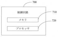
第3態様では、動力電池加熱システムの制御回路を提供し、第1態様及びいずれかの可能な実施形態の制御方法を実行するためのプロセッサを含む。In a third aspect, a control circuit for a power battery heating system is provided, the control circuit including a processor for executing the control method of the first aspect and any possible embodiment.
第4態様では、動力装置を提供し、動力電池及び第2態様の動力電池加熱システムを含む。In a fourth aspect, a power device is provided, comprising a power battery and the power battery heating system of the second aspect.
本願の実施例の技術案をより明確に説明するために、以下、本願の実施例に使用される必要がある図面を簡単に説明し、明らかに、以下に説明される図面は本願のいつくかの実施例に過ぎず、当業者にとって、創造的な労力を必要とせずに、それらの図面に基づいて他の図面を取得することもできる。
以下、図面及び実施例を参照しながら、本願の実施形態をさらに詳細に説明する。以下の実施例の詳細な説明及び図面は本願の原理を例示的に説明するためのものであるが、本願の範囲を制限するためのものではなく、すなわち本願は説明される実施例に限定されない。The following describes the embodiments of the present application in more detail with reference to the drawings and examples. The detailed description of the examples and the drawings below are intended to illustratively explain the principles of the present application, but are not intended to limit the scope of the present application, i.e., the present application is not limited to the examples described.
なお、本願の説明では、別途説明しない限り、「複数」の意味は2つ以上であり、「上」、「下」、「左」、「右」、「内」、「外」等の用語が示す方位又は位置関係は、本願の説明を容易にし、説明を簡素化するためのものに過ぎず、装置又は素子が特定の方位にあり、特定の方位で構造され、操作される必要があることを明示又は暗示することではなく、従って、本願に対する制限と理解されてはならない。また、「第1」、「第2」、「第3」等の用語は説明ためのものに過ぎず、相対的な重要性を明示又は暗示するものと理解されてはならない。「垂直」は厳密な意味での垂直ではなく、許容誤差範囲内のものである。「平行」は厳密な意味での平行ではなく、許容誤差範囲内のものである。In the description of this application, unless otherwise specified, "plurality" means two or more, and the orientation or positional relationship indicated by terms such as "upper," "lower," "left," "right," "inner," and "outer" is merely for the purpose of facilitating and simplifying the description of this application, and does not expressly or imply that a device or element is in a particular orientation, constructed, or operated in a particular orientation, and therefore should not be understood as a limitation on this application. In addition, terms such as "first," "second," and "third" are merely for the purpose of explanation, and should not be understood as expressing or implying relative importance. "Perpendicular" does not mean perpendicular in the strict sense, but within a tolerance range. "Parallel" does not mean parallel in the strict sense, but within a tolerance range.
以下の説明に現れる方位詞はいずれも図面に示される方向であり、本願の具体的な構造を限定するものではない。なお、本願の説明では、明確な規定や限定がない限り、「取り付け」、「連結」、「接続」という用語は広く理解されるべきであり、例えば、固定接続であってもよく、着脱可能な接続、又は一体的な接続であってもよく、直接接続であってもよく、中間媒体を介した間接接続であってもよい。当業者にとって、具体的な場合により上記用語の本願における具体的な意味を理解することができる。Any directional terms that appear in the following description are directions shown in the drawings and do not limit the specific structure of the present application. In the description of this application, unless otherwise clearly specified or limited, the terms "attached," "coupled," and "connected" should be understood broadly, and may refer to, for example, a fixed connection, a detachable connection, or an integral connection, a direct connection, or an indirect connection via an intermediate medium. Those skilled in the art will be able to understand the specific meaning of the above terms in the present application depending on the specific case.
時代の発展に伴い、新エネルギー自動車は、環境にやさしく、ノイズが低く、使用コストが低い等の利点のため、市場での将来性が高く、かつ省エネルギー及び排出削減を効果的に促進することができ、社会の発展及び進歩に有利である。As the times develop, new energy vehicles have great market potential due to their advantages such as environmental friendliness, low noise and low usage costs, and can effectively promote energy conservation and emission reduction, which is beneficial to the development and progress of society.
動力電池の電気化学特性により、低温環境で、動力電池の充放電能力が大幅に制限され、利用者が冬に自動車を使用する際の体験に深刻な影響を与える。従って、動力電池を正常に使用できるために、低温環境で動力電池を加熱する必要がある。Due to the electrochemical characteristics of the power battery, the charging and discharging capability of the power battery is significantly limited in a low temperature environment, which seriously affects the user's experience when using the car in winter. Therefore, in order to ensure that the power battery can be used normally, it is necessary to heat the power battery in a low temperature environment.
本願の実施例の動力電池は、リチウムイオン電池、リチウム金属電池、鉛酸電池、ニッケルカドミウム電池、ニッケル水素電池、リチウム硫黄電池、リチウム空気電池又はナトリウムイオン電池等であってもよいが、ここで限定しない。規模から言えば、本願の実施例の電池は単セルであってもよく、電池モジュール又は電池パックであってもよいが、ここで限定しない。適用シーンから言えば、電池は自動車、汽船等の動力装置に適用できる。例えば、動力自動車に適用でき、動力自動車のモーターに給電し、電気自動車の動力源とする。電池は、電気自動車内の他の電気機器、例えば、車内エアコン、車載プレーヤー等に給電することもできる。The power battery in the embodiment of the present application may be, but is not limited to, a lithium ion battery, a lithium metal battery, a lead acid battery, a nickel cadmium battery, a nickel metal hydride battery, a lithium sulfur battery, a lithium air battery, or a sodium ion battery. In terms of scale, the battery in the embodiment of the present application may be, but is not limited to, a single cell, a battery module, or a battery pack. In terms of application scenarios, the battery can be applied to power devices such as automobiles and steamships. For example, the battery can be applied to a power vehicle to power the motor of the power vehicle and serve as the power source for the electric vehicle. The battery can also power other electrical devices in the electric vehicle, such as the in-car air conditioner and the in-car player.
説明の便宜上、以下、動力電池が新エネルギー自動車(動力自動車)に適用されることを実施例として説明する。For ease of explanation, the following will be described as an example in which the power battery is applied to a new energy vehicle (powered vehicle).
駆動モーター及びその制御システムは新エネルギー自動車のコア部材の1つであり、その駆動特性は自動車走行の主な性能指標を決める。新エネルギー自動車のモーター駆動システムは主に電動機(すなわちモーター)、電力変換器、モーター制御ユニット(例えば、インバーター)、様々な検出センサ及び電源等の部分で構成される。モーターは、電磁誘導原理を応用して作動する回転電磁機械であり、電気エネルギーから機械的エネルギーへの変換を実現することに用いられる。作動中、電気システムから電力を吸収し、機械システムに機械的電力を出力する。The drive motor and its control system are one of the core components of new energy vehicles, and their drive characteristics determine the main performance indicators of vehicle operation. The motor drive system of a new energy vehicle is mainly composed of an electric motor (i.e., motor), a power converter, a motor control unit (e.g., inverter), various detection sensors, a power supply and other parts. A motor is a rotating electromagnetic machine that works by applying the principle of electromagnetic induction and is used to realize the conversion of electrical energy into mechanical energy. During operation, it absorbs power from the electrical system and outputs mechanical power to the mechanical system.
動力電池を加熱するときに不要なコストを増加させることを回避するために、モーター回路を利用して動力電池を加熱してもよい。To avoid unnecessary cost increases when heating the power battery, the motor circuit may be used to heat the power battery.
図1は従来の動力電池加熱システムの回路図を示す。図1に示すように、該動力電池加熱システム100は給電モジュール110、給電モジュール110に接続されるスイッチモジュール120及びスイッチモジュール120に接続されるモーター巻線130を含んでもよい。
給電モジュール110については、動力電池自体で実現されるだけでなく、充電ポスト等の外部給電モジュールで実現されてもよい。該外部給電モジュールが提供する加熱エネルギーは、例えば外部直流充電器によって出力されてもよく、又は外部交流充電器によって整流された後に出力されてもよいが、ここで具体的に制限しない。 1 shows a circuit diagram of a conventional power battery heating system. As shown in FIG. 1, the power
The
スイッチモジュール120については、様々なタイプのスイッチで実現されてもよい。例えば、該スイッチモジュール120はモーター駆動システムにおけるインバーターによって実現されてもよく、該インバーターは絶縁ゲートバイポーラトランジスタ(Insulated Gate Bipolar Transistor、IGBT)のブリッジアームスイッチで実現されてもよい。具体的に、該インバーターのブリッジアームの数はモーター巻線130の巻線の数と同じである。例えば、該モーター巻線130が3相巻線を含む場合、該インバーターは3相ブリッジアームを含み、すなわち、U相ブリッジアーム、V相ブリッジアーム及びW相ブリッジアームを含む。該3相ブリッジアーム内の各相ブリッジアームはいずれも上部ブリッジアーム及び下部ブリッジアームを含み、上部ブリッジアーム及び下部ブリッジアームにはそれぞれスイッチユニットが設置され、すなわち、スイッチモジュール120はそれぞれU相ブリッジアームの上部ブリッジアームスイッチ121と下部ブリッジアームスイッチ122、V相ブリッジアームの上部ブリッジアームスイッチ123と下部ブリッジアームスイッチ124、及びW相ブリッジアームの上部ブリッジアームスイッチ125と下部ブリッジアームスイッチ126を含む。 The
モーター巻線130については、具体的に、U相ブリッジアームに接続される巻線131、V相ブリッジアームに接続される巻線132及びW相ブリッジアームに接続される巻線133を含んでもよい。巻線131の一端はU相ブリッジアームの上部ブリッジアームと下部ブリッジアームとの接続点に接続され、巻線132の一端はV相ブリッジアームの上部ブリッジアームと下部ブリッジアームとの接続点に接続され、巻線133の一端はW相ブリッジアームの上部ブリッジアームと下部ブリッジアームとの接続点に接続される。巻線131の他端、巻線132の他端及び巻線133の他端は一体に接続される。Specifically, the motor winding 130 may include a winding 131 connected to the U-phase bridge arm, a winding 132 connected to the V-phase bridge arm, and a winding 133 connected to the W-phase bridge arm. One end of the winding 131 is connected to a connection point between the upper bridge arm and the lower bridge arm of the U-phase bridge arm, one end of the winding 132 is connected to a connection point between the upper bridge arm and the lower bridge arm of the V-phase bridge arm, and one end of the winding 133 is connected to a connection point between the upper bridge arm and the lower bridge arm of the W-phase bridge arm. The other end of the winding 131, the other end of the winding 132, and the other end of the winding 133 are connected together.
なお、該モーター巻線130は3相モーターに限定されず、6相モーター等であってもよく、対応して、該スイッチモジュール120は6相ブリッジアームを含んでもよい。The motor winding 130 is not limited to a three-phase motor, but may be a six-phase motor, etc., and correspondingly, the
いくつかの実施例では、スイッチモジュール120におけるスイッチの周期的なオンオフを制御することにより電流を変調させることができる。例えば、インバーターにおける対象上部ブリッジアームスイッチ及び対象下部ブリッジアームスイッチの周期的なオンオフを制御することにより電流を変調させる。一例では、対象上部ブリッジアームスイッチが上部ブリッジアームスイッチ121である場合、対象下部ブリッジアームスイッチは下部ブリッジアームスイッチ124及び/又は下部ブリッジアームスイッチ126である。別の例では、対象上部ブリッジアームスイッチが上部ブリッジアームスイッチ123である場合、対象下部ブリッジアームスイッチは下部ブリッジアームスイッチ122及び/又は下部ブリッジアームスイッチ126である。別の例では、対象上部ブリッジアームスイッチが上部ブリッジアームスイッチ125である場合、対象下部ブリッジアームスイッチは122及び/又は下部ブリッジアームスイッチ124である。In some embodiments, the current can be modulated by controlling the periodic on/off of the switches in the
なお、周期的にオン及びオフにされる各周期の対象上部ブリッジアームスイッチ及び対象下部ブリッジアームスイッチは同じであってもよく、異なってもよいが、ここで限定しない。例えば、各周期にいずれも上部ブリッジアームスイッチ121及び下部ブリッジアームスイッチ124のオン及びオフを制御する。また例えば、第1の周期に、上部ブリッジアームスイッチ121及び下部ブリッジアームスイッチ124のオン及びオフを制御し、第2の周期に、上部ブリッジアームスイッチ123及び下部ブリッジアームスイッチ122のオン及びオフを制御し、第3の周期に、上部ブリッジアームスイッチ121、下部ブリッジアームスイッチ124及び下部ブリッジアームスイッチ126のオン及びオフを制御し、すなわち、異なる周期に制御される対象上部ブリッジアームスイッチ及び下部ブリッジアームスイッチは異なってもよい。The target upper bridge arm switch and the target lower bridge arm switch that are periodically turned on and off in each period may be the same or different, but this is not limited here. For example, the upper
対象上部ブリッジアームスイッチ及び対象下部ブリッジアームスイッチの周期的なオン及びオフを制御することにより、給電モジュール、対象上部ブリッジアームスイッチ、対象下部ブリッジアームスイッチ及びモーター巻線の間に形成される異なる回路の電流方向が異なり、それにより交流電流が生じ、すなわち給電モジュールは充電と放電とを交互に行う。By controlling the periodic on and off of the target upper bridge arm switch and the target lower bridge arm switch, the current directions of the different circuits formed between the power supply module, the target upper bridge arm switch, the target lower bridge arm switch and the motor winding are different, thereby generating an alternating current, i.e., the power supply module alternates between charging and discharging.
対象オンスイッチは、少なくとも1つの上部ブリッジアームスイッチ及び少なくとも1つの下部ブリッジアームスイッチを含み、少なくとも1つの上部ブリッジアームスイッチ及び少なくとも1つの下部ブリッジアームスイッチは異なるブリッジアームに位置する。The target on switch includes at least one upper bridge arm switch and at least one lower bridge arm switch, where the at least one upper bridge arm switch and the at least one lower bridge arm switch are located on different bridge arms.
図1に示される動力電池加熱システムを使用し、モーター巻線を流れる3相電流が対称ではなく、かつ電流周波数が高いため、モーター回路を利用して動力電池を加熱する過程で、モーターの振動ノイズが大きすぎるという問題が存在する。When using the power battery heating system shown in Figure 1, the three-phase current flowing through the motor windings is not symmetrical and the current frequency is high, so there is a problem that the motor vibration noise is too large in the process of heating the power battery using the motor circuit.
本願の実施例は動力電池加熱システムの制御方法を提供し、スイッチモジュールを制御することにより、給電モジュール、スイッチモジュール及びモーター巻線の間に回路を形成させ、かつモーター巻線に流入する電流の合成磁界を0~0.5Tに制御し、それにより、モーター回路を利用して動力電池を加熱する過程で、モーターの振動ノイズが大きすぎるという問題を効果的に低減させることができる。The embodiment of the present application provides a control method for a power battery heating system, which controls a switch module to form a circuit between the power supply module, the switch module, and the motor winding, and controls the composite magnetic field of the current flowing into the motor winding to 0-0.5 T, thereby effectively reducing the problem of excessive motor vibration noise in the process of using the motor circuit to heat the power battery.
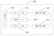
図2は本願の実施例に係る動力電池加熱システム200の模式的なブロック図を示す。図2に示すように、該動力電池加熱システム200は、複数の第1巻線210、複数の第2巻線220、第1スイッチ群230、第2スイッチ群240、給電モジュール250及び制御モジュール260を含む。
該第1スイッチ群230は該複数の第1巻線210に接続され、該第2スイッチ群240は該複数の第2巻線220に接続される。理解されるように、該「接続」は物理的に直接接続されてもよく、他のデバイスを介して接続されてもよい。 2 shows a schematic block diagram of a power
The
該複数の第1巻線210及び該複数の第2巻線220の数はいずれも3の倍数であり、かつ該複数の第1巻線210及び該複数の第2巻線220はいずれも第1モーターの巻線であってもよい。例えば、該第1モーターは6相モーターであり、該複数の第1巻線210は該6相モーターの3つの巻線であり、該複数の第2巻線220は該6相モーターの他の3つの巻線である。また例えば、該第1モーターは12相モーターであり、該複数の第1巻線210は12相モーターの6つの巻線であり、該複数の第2巻線220は12相モーターの他の6つの巻線である。The number of the
該第1スイッチ群230及び該第2スイッチ群240はスイッチモジュールと総称されてもよく、つまり、スイッチモジュールは該第1スイッチ群230及び該第2スイッチ群240を含む。The
該制御モジュール260は、該第1スイッチ群230及び該第2スイッチ群240のスイッチ状態を制御し、該第1スイッチ群230、該複数の第1巻線210、該複数の第2巻線220、該第2スイッチ群240及び該給電モジュール250の間の回路を形成し、電流に動力電池内で熱を発生させ、該動力電池を加熱することに用いられる。The
該複数の第1巻線210及び該複数の第2巻線220を流れる電流の合成磁界はいずれも0~0.5Tである。The composite magnetic field of the currents flowing through the
図1の制御方式と同様に、制御モジュール260は第1スイッチ群230及び第2スイッチ群240内のスイッチの周期的なオン及びオフを制御することにより、給電モジュール250、第1スイッチ群230、第2スイッチ群240、複数の第1巻線210及び複数の第2巻線220の間に形成される回路に交流電流を生じさせる。例えば、第1の周期内に、制御モジュール260は第1スイッチ群230及び第2スイッチ群240内のスイッチを制御して電流を給電モジュールの正方向から負方向へ流入し、すなわち第1回路を形成し、放電回路とも呼ばれ、第2の周期内に、制御モジュール260は第1スイッチ群230及び第2スイッチ群240内のスイッチを制御して電流を給電モジュールの負方向から正方向へ流入し、すなわち第2回路を形成し、充電回路とも呼ばれ、該第1回路及び該第2回路は電流に動力電池内で熱を発生させ、それにより動力電池を加熱することに用いられる。
また、第1スイッチ群230及び第2スイッチ群240内のスイッチを周期的にオン及びオフにすることは、つまり、予め設定された周波数で第1スイッチ群230及び第2スイッチ群240内のスイッチを交互にオン及びオフにすることを指す。 Similar to the control scheme of Fig. 1, the
Furthermore, periodically turning on and off the switches in the
単方向巻線の起磁力は、空間に段階的に分布し、時間に伴って電流変化の法則に従って変化する脈動起磁力である。3相モーターの3つの単相巻線の起磁力を重ね合わせると、3相巻線の合成磁界になる。通常、加熱過程で3相モーターの3相巻線に流入する電流は、大きさが完全に同じではなく、その2相の巻線を流れる電流は、位相差が180°であり、位相差のない2相の電流の大きさは同じである。モーター巻線を流れる3相電流は相互に対称ではなくなり、かつ電流周波数が高いため、動力電池の加熱過程でモーターの振動ノイズが大きいという問題をもたらす。本願では、同一モーターに属する複数の第1巻線210及び複数の第2巻線220に流入する電流の合成磁界を所定の範囲内、例えば、0~0.5Tに制御することにより、モーター回路を利用して動力電池を加熱するときに生じた振動ノイズを効果的に抑制する。また、同一モーターに属する複数の第1巻線210及び複数の第2巻線220に流入する電流の合成磁界をいずれも0~0.5Tに制御することにより、モーターを作動させることがなく、モーターの回転子の発熱問題をさらに解決でき、それにより電池の自己加熱の使用時間を延長させる。The magnetomotive force of a unidirectional winding is a pulsating magnetomotive force that is distributed in a space in stages and changes according to the law of current change over time. When the magnetomotive forces of the three single-phase windings of a three-phase motor are superimposed, it becomes a composite magnetic field of the three-phase windings. Usually, the currents flowing into the three-phase windings of a three-phase motor during the heating process are not completely the same in magnitude, and the currents flowing through the two phase windings have a phase difference of 180°, and the magnitudes of the currents of the two phases without phase difference are the same. The three-phase currents flowing through the motor windings are no longer symmetrical to each other, and the current frequency is high, which causes a problem that the motor vibration noise is large during the heating process of the power battery. In the present application, the composite magnetic field of the currents flowing into the multiple
選択可能に、本願の実施例では、該動力電池加熱システム200は6相モーター、スイッチモジュール、制御モジュール260及び給電モジュール250を含み、該6相モーターは3つの第1巻線210及び3つの第2巻線220を含み、該スイッチモジュールの第1スイッチ群230は第1ブリッジアーム群であり、該スイッチモジュールの第2スイッチ群240は第2ブリッジアーム群であり、該第1ブリッジアーム群及び該第2ブリッジアーム群内の各ブリッジアームはそれぞれ上部ブリッジアーム及び下部ブリッジアームを含み、該第1ブリッジアーム群内の各ブリッジアームの上部ブリッジアームと下部ブリッジアームとの接続点は3つの第1巻線と一対一で対応して接続され、該第2ブリッジアーム群内の各ブリッジアームの上部ブリッジアームと下部ブリッジアームとの接続点は3つの第2巻線と一対一で対応して接続され、該第1ブリッジアーム群及び該第2ブリッジアーム群はいずれも給電モジュールに並列接続される。Optionally, in an embodiment of the present application, the power
該制御モジュール260は、該第1ブリッジアーム群のすべての上部ブリッジアームのオン、該第1ブリッジアーム群のすべての下部ブリッジアームのオフ、該第2ブリッジアーム群のすべての下部ブリッジアームのオン及び該第2ブリッジアーム群のすべての上部ブリッジアームのオフを制御して、該第1ブリッジアーム群のすべての上部ブリッジアーム、該3つの第1巻線、該3つの第2巻線、該第2ブリッジアーム群のすべての下部ブリッジアーム及び該給電モジュールの間の第1回路を形成するための第1加熱信号を該スイッチモジュールに送信すること、及び該第1ブリッジアーム群のすべての下部ブリッジアームのオン、該第1ブリッジアーム群のすべての上部ブリッジアームのオフ、該第2ブリッジアーム群のすべての上部ブリッジアームのオン及び該第2ブリッジアーム群のすべての下部ブリッジアームのオフを制御して、該第1ブリッジアーム群のすべての下部ブリッジアーム、該3つの第1巻線、該3つの第2巻線、該第2ブリッジアーム群のすべての上部ブリッジアーム及び該給電モジュールの間の第2回路を形成するための第2加熱信号を該スイッチモジュールに送信することに用いられ、該第1回路及び該第2回路は電流に動力電池内で熱を発生させ、該動力電池を加熱することに用いられる。The
該3つの第1巻線210の空間位相差は120°であり、該3つの第2巻線220の空間位相差は120°である。The spatial phase difference between the three
電流が6相モーターの3つの第1巻線の間に流入する空間位相差を120°に制御し、かつ電流が6相モーターの他の3つの第2巻線の間から流出する空間位相差を120°に制御することにより、該6相モーターの回路を利用して動力電池を加熱するとき、モーターの振動ノイズを効果的に抑制することができる。また、本願に係る動力電池加熱システムは、モーターを作動させることがないため、モーターの回転子の発熱問題を解決でき、それにより、電池の自己加熱の使用時間を延長させる。
以下、図3及び図4を参照しながら、本願の実施例に係る動力電池加熱システム400の回路図を詳細に説明する。 By controlling the spatial phase difference of the current flowing in between the three first windings of the six-phase motor to 120° and controlling the spatial phase difference of the current flowing out between the other three second windings of the six-phase motor to 120°, the vibration noise of the motor can be effectively suppressed when the power battery is heated using the circuit of the six-phase motor. In addition, the power battery heating system of the present application can solve the heat generation problem of the motor rotor since the motor is not operated, thereby extending the use time of the battery self-heating.
Hereinafter, a circuit diagram of a power battery heating system 400 according to an embodiment of the present application will be described in detail with reference to FIG. 3 and FIG.
図3及び図4に示すように、第1モーターは6相モーターであり、該複数の第1巻線はそれぞれ6相モーターの巻線311、巻線312及び巻線313であり、該複数の第2巻線はそれぞれ6相モーターの巻線314、巻線315及び巻線316である。該第1ブリッジアーム群はスイッチモジュールのブリッジアーム331、ブリッジアーム332及びブリッジアーム333である。該第2ブリッジアーム群はスイッチモジュールのブリッジアーム334、ブリッジアーム335及びブリッジアーム336である。As shown in Figures 3 and 4, the first motor is a six-phase motor, the multiple first windings are respectively
具体的に、ブリッジアーム331の上部ブリッジアーム3311と下部ブリッジアーム3312との接続点は巻線311の一端に接続され、ブリッジアーム332の上部ブリッジアーム3321と下部ブリッジアーム3322との接続点は巻線312の一端に接続され、ブリッジアーム333の上部ブリッジアーム3331と下部ブリッジアーム3332との接続点は巻線313の一端に接続され、ブリッジアーム334の上部ブリッジアーム3341と下部ブリッジアーム3342との接続点は巻線314の一端に接続され、ブリッジアーム335の上部ブリッジアーム3351と下部ブリッジアーム3352との接続点は巻線315の一端に接続され、ブリッジアーム336の上部ブリッジアーム3361と下部ブリッジアーム3362との接続点は巻線316の一端に接続される。Specifically, the connection point between the
図3に示すように、給電モジュール350、上部ブリッジアーム3311~3331、巻線311~313、巻線314~316及び下部ブリッジアーム3342~3362は共に放電回路を形成し、同様に、図4に示すように、給電モジュール350、下部ブリッジアーム3312~3332、巻線311~313、巻線314~316及び上部ブリッジアーム3341~3361は共に充電回路を形成する。制御モジュール(図示せず)の制御により、充電回路及び放電回路は周期的で交互にオンにされる。As shown in FIG. 3, the
図3及び図4に示される実施例では、電流が巻線311~313の3つの巻線の間に流入する空間位相差を120°に制御し、かつ電流が巻線314~316の3つの巻線の間から流出する空間位相差を120°に制御することにより、該6相モーターの回路を利用して動力電池を加熱するとき、モーターの振動ノイズを効果的に抑制することができる。かつ本願の実施例に係る動力電池加熱システムはモーターを作動させることがないため、モーターの回転子の発熱問題を解決でき、それにより電池の自己加熱の使用時間を延長させる。In the embodiment shown in Figures 3 and 4, the spatial phase difference where the current flows in between the three windings 311-313 is controlled to 120°, and the spatial phase difference where the current flows out from between the three windings 314-316 is controlled to 120°, so that when the power battery is heated using the circuit of the six-phase motor, the vibration noise of the motor can be effectively suppressed. Furthermore, the power battery heating system according to the embodiment of the present application does not operate the motor, so the problem of heat generation in the motor rotor can be solved, thereby extending the usage time of the battery's self-heating.
巻線311~313を入力巻線としてもよく、巻線314~316を出力巻線としてもよい。代替的に、巻線311~313を出力巻線としてもよく、巻線314~316を入力巻線としてもよい。巻線311~313に接続される3相ブリッジアームの上部ブリッジアームと巻線314~316に接続される3相ブリッジアームの下部ブリッジアームとが同時にスイッチのオン又はオフを維持し、巻線311~313に接続される3相ブリッジアームの下部ブリッジアームと巻線314~316に接続される上部ブリッジアームとが同時にスイッチのオン又はオフを維持することを確保すれば、図3に示される放電回路及び図4に示される充電回路を実現できる。The windings 311-313 may be input windings and the windings 314-316 may be output windings. Alternatively, the windings 311-313 may be output windings and the windings 314-316 may be input windings. The discharge circuit shown in FIG. 3 and the charge circuit shown in FIG. 4 can be realized by ensuring that the upper bridge arm of the three-phase bridge arm connected to the windings 311-313 and the lower bridge arm of the three-phase bridge arm connected to the windings 314-316 simultaneously maintain the switch on or off, and that the lower bridge arm of the three-phase bridge arm connected to the windings 311-313 and the upper bridge arm connected to the windings 314-316 simultaneously maintain the switch on or off.
選択可能に、本願の実施例では、複数の第1巻線の空間位相差は360°とMの比であってもよく、複数の第2巻線の空間位相差は360°とNの比であってもよく、ここで、Mは複数の第1巻線の数であり、Nは複数の第2巻線の数であり、(M+N)は第1モーターの巻線の数である。例えば、該第1モーターが12相モーターであり、該複数の第1巻線が12相モーターの6つの巻線であり、該複数の第2巻線が12相モーターの他の6つの巻線である場合、該6つの第1巻線の空間位相差は60°であり、6つの第2巻線の空間位相差は60°である。 Optionally, in embodiments of the present application, the spatial phase difference of the plurality of first windings may be in a ratio of 360° to M, and the spatial phase difference of the plurality of second windings may be in a ratio of 360° to N, where M is the number of the plurality of first windings, N is the number of the plurality of second windings, and (M+N) is the number ofwindings of the first motor. For example, if the first motor is a 12-phase motor, the plurality of first windings are six windings of the 12-phase motor, and the plurality of second windings are the other six windings of the 12-phase motor, then the spatial phase difference of the six first windings is 60°, and the spatial phase difference of the six second windings is 60°.
選択可能に、制御モジュールは、予め設定された周波数で、スイッチモジュールに第1加熱信号及び第2加熱信号を交互に送信することに用いられる。つまり、制御モジュールはスイッチモジュールに第1加熱信号を送信するときにタイミングを開始し、所定時間後にスイッチモジュールに第2加熱信号を送信する。次に、制御モジュールはスイッチモジュールに第2加熱信号を送信するときにタイミングを開始し、所定時間後にスイッチモジュールに第1加熱信号を再び送信し、このように繰り返して順にスイッチモジュールに第1加熱信号及び第2加熱信号を送信する。Optionally, the control module is adapted to alternately transmit a first heating signal and a second heating signal to the switch module at a preset frequency. That is, the control module initiates timing when it transmits a first heating signal to the switch module, and transmits a second heating signal to the switch module after a predetermined time. The control module then initiates timing when it transmits a second heating signal to the switch module, and transmits the first heating signal again to the switch module after a predetermined time, and so on in a repeating manner to transmit the first heating signal and the second heating signal to the switch module in turn.
選択可能に、本願の実施例では、該給電モジュールは動力電池であり、該制御モジュールはさらに、該動力電池の荷電状態SOCを決定すること、該SOCが第1閾値よりも大きい場合、スイッチモジュールに第1加熱信号及び第2加熱信号を送信し、言い換えれば、該回路を流れる電流を交流電流に変調させること、及び、該SOCが該第1閾値以下である場合、スイッチモジュールのスイッチの閉じ又はオフを制御するための第3加熱信号をスイッチモジュールに送信することにより、回路の電流方向を一定にし、すなわち、該回路を流れる電流を直流電流に変調させ、それにより、該第1モーターに生じた熱を車両の冷却システムを介して動力電池に伝達し、動力電池を加熱することに用いられる。Optionally, in an embodiment of the present application, the power supply module is a power battery, and the control module is further used to determine the state of charge SOC of the power battery, and if the SOC is greater than a first threshold, send a first heating signal and a second heating signal to the switch module, in other words, modulate the current flowing through the circuit to an AC current, and if the SOC is less than or equal to the first threshold, send a third heating signal to the switch module for controlling the closing or turning off of the switch of the switch module, thereby making the current direction of the circuit constant, i.e., modulating the current flowing through the circuit to a DC current, thereby transferring the heat generated in the first motor to the power battery via the vehicle's cooling system and heating the power battery.
荷電状態(State Of Charge、SOC)とは、電池の所定の放電率で、残量と同一条件での定格容量との比である。SOCは電池管理システムの重要なパラメータの1つであり、自動車全体の充放電制御戦略及び電池バランス作動の根拠でもある。しかし、リチウム電池そのものの構造の複雑さにより、その荷電状態を直接測定することにより得ることができず、電池のある外部特性、例えば電池の内部抵抗、温度、電流等の関連パラメータに基づいて、関連する特性曲線又は計算式でSOCに対する推算を完了することしかできない。State of charge (SOC) is the ratio of the remaining charge to the rated capacity under the same conditions at a given discharge rate of the battery. SOC is one of the important parameters of the battery management system and is also the basis for the overall charge and discharge control strategy of the vehicle and the battery balancing operation. However, due to the complexity of the structure of the lithium battery itself, its state of charge cannot be obtained by direct measurement, and the SOC can only be estimated based on certain external characteristics of the battery, such as related parameters such as the battery's internal resistance, temperature, and current, using the relevant characteristic curves or calculation formulas.
本願の実施例は温度が低い動力電池を加熱するシーンに適用できる。例えば、動力電池を加熱することにより、動力電池の温度を、電池パックが正常に使用できる温度に達するまで上昇させるという具体的なシーンに適用できる。具体的に、本願の実施例では、動力電池のSOCが第1閾値よりも大きいとき、回路を流れる電流を交流電流に変調させることができ、交流電流を利用して動力電池の内部抵抗によって発熱し、それにより動力電池を加熱し、加熱効率を向上させることができ、電池SOCが第1閾値以下であるとき、すなわち、電池の電気量が不十分であるとき、直流電流を利用して巻線に熱を発生させて動力電池を加熱し、電気量消耗を低減させ、動力電池の加熱システムの柔軟性を向上させることができる。The embodiments of the present application can be applied to a scene where a low-temperature power battery is heated. For example, the embodiment can be applied to a specific scene where the temperature of the power battery is increased by heating the power battery until the temperature of the battery pack can be normally used. Specifically, in the embodiments of the present application, when the SOC of the power battery is greater than a first threshold, the current flowing through the circuit can be modulated to an AC current, and the AC current is used to generate heat through the internal resistance of the power battery, thereby heating the power battery and improving the heating efficiency. When the battery SOC is equal to or less than the first threshold, i.e., when the battery has insufficient electrical charge, a DC current is used to generate heat in the windings to heat the power battery, thereby reducing electrical charge consumption and improving the flexibility of the power battery heating system.
選択可能に、制御モジュールは、最初に、モーター回路を流れる電流を直流電流にするように第1スイッチ群及び第2スイッチ群を制御し、動力電池のSOCを周期的に決定し、動力電池のSOCが第1閾値よりも大きいと決定すると、モーター回路を流れる電流を交流電流にするように第1スイッチ群及び第2スイッチ群を制御し、交流電流を利用して動力電池の内部抵抗によって発熱して動力電池を加熱し、それにより加熱効率を向上させることができる。Optionally, the control module first controls the first and second switch groups to make the current flowing through the motor circuit a direct current, periodically determines the SOC of the power battery, and when it determines that the SOC of the power battery is greater than a first threshold, controls the first and second switch groups to make the current flowing through the motor circuit an alternating current, and uses the alternating current to generate heat through the internal resistance of the power battery to heat the power battery, thereby improving heating efficiency.
いくつかの実施例では、空間ベクトルパルス幅変調Space Vector Pulse Width Modulation、SVPWM)アルゴリズムでモーター巻線の電流を直流電流又は交流電流に変調させてもよい。In some embodiments, the current in the motor windings may be modulated to DC or AC using a Space Vector Pulse Width Modulation (SVPWM) algorithm.
なお、モーター巻線に直流電流が流れるとき、モーターの半径方向電磁力を減少させ、モーター回転子の渦電流損失を低減させ、それにより、回転子の発熱量を低減させる。従って、モーター巻線に直流電流が流れるとき、モーター回転子の発熱量及び電磁振動ノイズを低減させる。When a direct current flows through the motor windings, the radial electromagnetic force of the motor is reduced, and the eddy current loss in the motor rotor is reduced, thereby reducing the amount of heat generated by the rotor. Therefore, when a direct current flows through the motor windings, the amount of heat generated by the motor rotor and the electromagnetic vibration noise are reduced.
選択可能に、本願の実施例では、該制御モジュールは具体的に、該第1モーターの作動状態を取得すること、及び該第1モーターが非駆動状態にあるとき、該スイッチモジュールに第1加熱信号及び第2加熱信号を送信することに用いられる。Optionally, in the embodiment of the present application, the control module is specifically used to obtain the operating state of the first motor, and to send a first heating signal and a second heating signal to the switch module when the first motor is in a non-driving state.
モーターの作動状態を判断することにより、モーターが駆動状態にあるときに動力電池を加熱し、さらに車両等の動力装置の性能に影響を与えることを回避する。By determining the operating state of the motor, it is possible to avoid heating the power battery when the motor is in a driving state, which would further affect the performance of the power device of the vehicle, etc.
さらに、該制御モジュールは具体的に、第1モーターが非駆動状態にありかつ動力電池加熱システムに故障がないとき、該スイッチモジュールに第1加熱信号及び第2加熱信号を送信する。Furthermore, the control module specifically transmits a first heating signal and a second heating signal to the switch module when the first motor is in a non-driving state and there is no fault in the power battery heating system.
なお、本願の実施例では、電池加熱システムに故障があることとは、第1モーター、モーター制御ユニット、スイッチモジュール及び熱伝達回路等のいずれかに故障が発生することを指す。熱伝達回路に故障が発生することは、連通バルブが破損され、熱伝達回路内の媒体が不十分であるなどの問題を含むが、それらに限定されない。In the embodiments of the present application, a malfunction in the battery heating system refers to a malfunction occurring in any of the first motor, the motor control unit, the switch module, the heat transfer circuit, etc. Malfunctions in the heat transfer circuit include, but are not limited to, problems such as a broken communication valve and insufficient medium in the heat transfer circuit.
選択可能に、レンジ情報及びモーターの回転数情報を取得し、かつこれに基づいて第1モーターが駆動状態にあるか非駆動状態にあるかを判断してもよい。具体的に、現在のレンジがPレンジでありかつ車速が0であると判定したとき、第1モーターが非駆動状態にあると示し、現在のレンジがPレンジではなく又は車速が0ではないと判定したとき、第1モーターが駆動状態にあると示す。Selectively, range information and motor RPM information may be acquired, and based on this, it may be determined whether the first motor is in a driven state or a non-driven state. Specifically, when it is determined that the current range is P range and the vehicle speed is 0, it indicates that the first motor is in a non-driven state, and when it is determined that the current range is not P range or the vehicle speed is not 0, it indicates that the first motor is in a driven state.
レンジ情報及びモーターの回転数情報によって判断し、いずれかの条件を満たさないとき、第1モーターに加熱信号を送信せず、車両が正常に走行する状態で動力電池を加熱し、さらに車両性能に影響を与えることを回避する。The system determines whether or not any of the conditions are met based on range information and motor RPM information. If this is not the case, it does not send a heating signal to the first motor, and instead heats the power battery while the vehicle is running normally, thus avoiding any adverse effect on vehicle performance.
選択可能に、本願の実施例では、該制御モジュールはさらに、電池管理システムBMSから送信された、該動力電池が加熱条件を満たすことを指示するための加熱要求を受信することに用いられる。
BMSから送信された加熱要求を受信することにより、制御モジュールは動力電池をタイムリーに加熱することができ、車両等の動力装置の使用に影響を与えることを回避する。 Optionally, in an embodiment of the present application, the control module is further used for receiving a heating request sent from a battery management system BMS to indicate that the power battery meets a heating requirement.
By receiving the heating request sent from the BMS, the control module can heat the power battery in a timely manner to avoid affecting the use of the power device such as a vehicle.
選択可能に、本願の実施例では、該制御モジュールはさらに、該動力電池の温度が予め設定された温度に達し、又は、該動力電池の温度上昇が異常である場合、該スイッチモジュールに加熱停止信号を送信することに用いられ、該加熱停止信号は、スイッチモジュールを制御して、給電モジュール、スイッチモジュール、3つの第1巻線及び3つの第2巻線の間に回路を構成しないことにより、動力電池に対する加熱を停止する。Optionally, in an embodiment of the present application, the control module is further used to send a heating stop signal to the switch module when the temperature of the power battery reaches a preset temperature or the temperature rise of the power battery is abnormal, and the heating stop signal controls the switch module to stop heating the power battery by not forming a circuit between the power supply module, the switch module, the three first windings, and the three second windings.
選択可能に、本願の実施例では、制御モジュールは車両制御ユニット(Vehicle control unit、VCU)及び/又はモーター制御ユニットを含んでもよい。Optionally, in embodiments of the present application, the control module may include a vehicle control unit (VCU) and/or a motor control unit.
選択可能に、車両制御ユニットはBMSから送信された加熱要求を受信するとき、車両制御ユニットはモーター制御ユニットに制御信号を送信してもよく、該制御信号は動力電池を加熱することを指示することに用いられ、すなわち、該制御信号はスイッチモジュールに加熱信号を送信することをモーター制御ユニットに指示することに用いられる。例えば、モーター制御ユニットは車両制御ユニットから送信された制御信号を受信すると、スイッチモジュールに第1加熱信号を送信してもよく、該第1加熱信号は、スイッチモジュールを制御して、給電モジュール、スイッチモジュール、3つの第1巻線及び3つの第2巻線の間に第1回路を形成することに用いられ、所定時間後、モーター制御ユニットはスイッチモジュールに第2加熱信号を送信し、該第2加熱信号は、スイッチモジュールを制御して、給電モジュール、スイッチモジュール、3つの第1巻線及び3つの第2巻線の間に第2回路を形成することに用いられ、該第1回路及び第2回路における電流方向は逆であり、電流は順に3つの第1巻線から流入し、そして3つの第2巻線から流出する。Optionally, when the vehicle control unit receives a heating request sent from the BMS, the vehicle control unit may send a control signal to the motor control unit, which is used to instruct the power battery to heat up, i.e., the control signal is used to instruct the motor control unit to send a heating signal to the switch module. For example, when the motor control unit receives a control signal sent from the vehicle control unit, the motor control unit may send a first heating signal to the switch module, which is used to control the switch module to form a first circuit between the power supply module, the switch module, the three first windings and the three second windings, and after a predetermined time, the motor control unit sends a second heating signal to the switch module, which is used to control the switch module to form a second circuit between the power supply module, the switch module, the three first windings and the three second windings, and the current directions in the first circuit and the second circuit are reversed, and the current flows in from the three first windings and flows out from the three second windings in sequence.
選択可能に、図3及び図4に示される動力電池加熱システムは給電モジュールに並列接続されるコンデンサCをさらに含み、主に圧力安定化及びクラッタ濾過等の役割を果たす。Optionally, the power battery heating system shown in Figures 3 and 4 further includes a capacitor C connected in parallel to the power supply module, which mainly serves the functions of pressure stabilization and clutter filtering, etc.
以上、本願の実施例の動力電池加熱システムを詳細に説明しており、以下、図5及び図6を参照しながら本願の実施例の動力電池加熱システムの制御方法を詳細に説明する。装置の実施例に説明される技術的特徴は以下の方法の実施例に適用できる。The power battery heating system of the embodiment of the present application has been described in detail above. Below, the control method of the power battery heating system of the embodiment of the present application will be described in detail with reference to Figures 5 and 6. The technical features described in the device embodiment can be applied to the following method embodiment.
図5は本願の実施例の動力電池加熱システムの制御方法500の模式的なブロック図を示し、該動力電池加熱システムは上記説明されたいずれかの動力電池加熱システムである。該制御方法500は動力電池加熱システムの制御モジュール、例えば、車両制御ユニット及び/又はモーター制御ユニットによって実行されてもよく、該制御方法500は、
第1ブリッジアーム群のすべての上部ブリッジアームのオン、第1ブリッジアーム群のすべての下部ブリッジアームのオフ、第2ブリッジアーム群のすべての下部ブリッジアームのオン及び第2ブリッジアーム群のすべての上部ブリッジアームのオフを制御して、第1ブリッジアーム群のすべての上部ブリッジアーム、3つの第1巻線、3つの第2巻線、第2ブリッジアーム群のすべての下部ブリッジアーム及び給電モジュールの間の第1回路を形成するための第1加熱信号をスイッチモジュールに送信するステップS510と、
第1ブリッジアーム群のすべての下部ブリッジアームのオン、第1ブリッジアーム群のすべての上部ブリッジアームのオフ、第2ブリッジアーム群のすべての上部ブリッジアームのオン及び第2ブリッジアーム群のすべての下部ブリッジアームのオフを制御して、第1ブリッジアーム群のすべての下部ブリッジアーム、3つの第1巻線、3つの第2巻線、第2ブリッジアーム群のすべての上部ブリッジアーム及び給電モジュールの間の第2回路を形成するための第2加熱信号をスイッチモジュールに送信するステップS520と、を含み、
該第1回路及び該第2回路は電流に動力電池内で熱を発生させ、該動力電池を加熱することに用いられ、該3つの第1巻線の空間位相差は120°であり、該3つの第2巻線の空間位相差は120°である。 5 shows a schematic block diagram of a
S510: sending a first heating signal to the switch module to control all upper bridge arms of the first bridge arm group to be turned on, all lower bridge arms of the first bridge arm group to be turned off, all lower bridge arms of the second bridge arm group to be turned on, and all upper bridge arms of the second bridge arm group to be turned off, to form a first circuit among all upper bridge arms of the first bridge arm group, the three first windings, the three second windings, all lower bridge arms of the second bridge arm group, and the power supply module;
sending a second heating signal to the switch module to control turning on all the lower bridge arms of the first bridge arm group, turning off all the upper bridge arms of the first bridge arm group, turning on all the upper bridge arms of the second bridge arm group, and turning off all the lower bridge arms of the second bridge arm group to form a second circuit among all the lower bridge arms of the first bridge arm group, the three first windings, the three second windings, all the upper bridge arms of the second bridge arm group, and the power supply module;
The first circuit and the second circuit are used to cause a current to generate heat in the power battery and heat the power battery, and the spatial phase difference between the three first windings is 120°, and the spatial phase difference between the three second windings is 120°.
具体的に、本願の実施例では、車両制御ユニットは動力電池が加熱条件を満たすと判断した場合、動力電池を加熱することを指示するための制御信号をモーター制御ユニットに送信することができ、さらに、モーター制御ユニットはスイッチモジュールに第1加熱信号を送信し、該第1加熱信号は第1ブリッジアーム群のすべての上部ブリッジアーム、3つの第1巻線、3つの第2巻線、第2ブリッジアーム群のすべての下部ブリッジアーム及び給電モジュールの間に第1回路を形成するように制御し、モーター制御ユニットは第1加熱信号を送信した後の所定時間にスイッチモジュールに第2加熱信号を送信し、該第2加熱信号は第1ブリッジアーム群のすべての下部ブリッジアーム、3つの第1巻線、3つの第2巻線、第2ブリッジアーム群のすべての上部ブリッジアーム及び給電モジュールの間に第2回路を形成するように制御する。Specifically, in an embodiment of the present application, when the vehicle control unit determines that the power battery satisfies the heating condition, it can send a control signal to the motor control unit to instruct the power battery to be heated, and further, the motor control unit sends a first heating signal to the switch module, and the first heating signal controls the switch module to form a first circuit between all the upper bridge arms of the first bridge arm group, the three first windings, the three second windings, all the lower bridge arms of the second bridge arm group, and the power supply module, and the motor control unit sends a second heating signal to the switch module at a predetermined time after sending the first heating signal, and the second heating signal controls the switch module to form a second circuit between all the lower bridge arms of the first bridge arm group, the three first windings, the three second windings, all the upper bridge arms of the second bridge arm group, and the power supply module.
選択可能に、本願の実施例では、該スイッチモジュールに第1加熱信号及び第2加熱信号を送信するステップは、予め設定された周波数で、該スイッチモジュールに該第1加熱信号と該第2加熱信号を交互に送信するステップを含む。すなわち、該第1回路と該第2回路は交互に形成される。
選択可能に、本願の実施例では、該給電モジュールは動力電池であり、該スイッチモジュールに第1加熱信号及び第2加熱信号を送信するステップは、該動力電池の荷電状態SOCを決定するステップと、該SOCが第1閾値よりも大きい場合、該スイッチモジュールに該第1加熱信号及び該第2加熱信号を送信するステップと、を含む。 Optionally, in an embodiment of the present application, the step of transmitting a first heating signal and a second heating signal to the switch module includes the step of alternately transmitting the first heating signal and the second heating signal to the switch module at a preset frequency, i.e., the first circuit and the second circuit are alternately formed.
Optionally, in an embodiment of the present application, the power supply module is a power battery, and the step of sending the first heating signal and the second heating signal to the switch module includes the steps of determining a state of charge SOC of the power battery, and if the SOC is greater than a first threshold, sending the first heating signal and the second heating signal to the switch module.
選択可能に、本願の実施例では、該スイッチモジュールに第1加熱信号及び第2加熱信号を送信するステップは、6相モーターの作動状態を取得するステップと、該6相モーターが非駆動状態にある場合、該スイッチモジュールに該第1加熱信号及び該第2加熱信号を送信するステップと、を含む。
選択可能に、本願の実施例では、該制御方法は、動力電池の温度が予め設定された温度に達し、又は、該動力電池の温度上昇が異常である場合、該スイッチモジュールに加熱停止信号を送信するステップをさらに含む。 Optionally, in an embodiment of the present application, the step of sending a first heating signal and a second heating signal to the switch module includes the steps of obtaining an operating state of a six-phase motor, and when the six-phase motor is in a non-driving state, sending the first heating signal and the second heating signal to the switch module.
Optionally, in an embodiment of the present application, the control method further includes the step of sending a heating stop signal to the switch module when the temperature of the power battery reaches a preset temperature or the temperature rise of the power battery is abnormal.
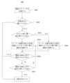
以下、それぞれ図3及び図4に示される動力電池加熱システム300を例として本願の実施例の動力電池加熱システムの制御方法を詳細に説明し、図6は制御方法600の模式的なフローチャートを示し、図6に示すように、該制御方法600は、ステップS601~S607を含む。
S601、BMSは電池パックの温度、SOC、電圧信号及び電流信号等の電池パラメータを収集する。 Hereinafter, the control method of the power battery heating system of the embodiment of the present application will be described in detail by taking the power
S601, the BMS collects battery parameters such as temperature, SOC, voltage signal and current signal of the battery pack.
S602、BMSは電池の各項のパラメータに基づいて加熱条件を満たすか否かを判断し、満たす場合、SOC状態に基づいて対応する加熱要求をVCUに送信し、例えば、予め設定された温度に加熱されるのに必要な電力をVCUに送信する。
S603、BMS又はVCUは電池SOCが第1閾値よりも大きいか否かを判断する。
S604、SOCが第1閾値よりも大きい場合、モーター回路を流れる交流電流により生じた熱で動力電池を加熱する。 S602, the BMS judges whether the heating condition is met based on the parameters of each item of the battery, and if so, sends a corresponding heating request to the VCU based on the SOC state, for example, sends the power required to heat to a preset temperature to the VCU.
S603, the BMS or the VCU determines whether the battery SOC is greater than a first threshold value.
S604, if the SOC is greater than the first threshold, the power battery is heated by the heat generated by the AC current flowing through the motor circuit.
S605、SOCが第1閾値以下である場合、モーター回路を流れる直流電流により生じた熱で動力電池を加熱する。S605: If the SOC is equal to or lower than the first threshold, the power battery is heated with heat generated by the direct current flowing through the motor circuit.
S604の後、VCUは第1モーターの現在の作動状態を読み取る。例えば、第1モーターが駆動状態(すなわち作動状態)にある場合、VCUは駆動信号をモーター制御ユニットに送信する。このとき、モーター制御ユニットは、スイッチモジュールに周期駆動信号を送信し、ブリッジアーム331~336の上部ブリッジアーム及び下部ブリッジアームがモーター制御ユニットから送信された周期駆動信号に基づいてスイッチのオンの切り替えを行うように制御し、電池電流の反転制御を実現する。第1モーターが非駆動状態にある場合、VCUは制御信号をモーター制御ユニットに送信する。このとき、モーター制御ユニットは、スイッチモジュールに第1加熱信号及び第2加熱信号を送信し、ブリッジアーム331~333の上部ブリッジアーム及びブリッジアーム334~336の下部ブリッジアーム、ブリッジアーム331~333の下部ブリッジアーム及びブリッジアーム334~336の上部ブリッジアームが同時にスイッチのオン及びオフを維持するように交互に制御する。After S604, the VCU reads the current working state of the first motor. For example, if the first motor is in a driving state (i.e., in a working state), the VCU sends a driving signal to the motor control unit. At this time, the motor control unit sends a periodic driving signal to the switch module, and controls the upper bridge arms and the lower bridge arms of the bridge arms 331-336 to switch on and off based on the periodic driving signal sent from the motor control unit, thereby realizing the reversal control of the battery current. If the first motor is in a non-driving state, the VCU sends a control signal to the motor control unit. At this time, the motor control unit sends a first heating signal and a second heating signal to the switch module, and alternately controls the upper bridge arms of the bridge arms 331-333 and the lower bridge arms of the bridge arms 334-336, the lower bridge arms of the bridge arms 331-333 and the upper bridge arms of the bridge arms 334-336 to keep switching on and off at the same time.
具体的に、ブリッジアーム331~333の上部ブリッジアーム3311、3321及び3331と、ブリッジアーム334~336の下部ブリッジアーム3342、3352、3362とがオンになり、ブリッジアーム331~333の下部ブリッジアーム3312、3322及び3332と、ブリッジアーム334~336の上部ブリッジアーム3341、3351、3361とがオフになるとき、電池350は放電し、放電回路は、350(+)→(3311/3321/3331)→(311/312/313)→(314/315/316)→(3342/3352/3362)→350(-)であり、電流状態は図3に示される。ブリッジアーム331~333の下部ブリッジアーム3312、3322及び3332と、ブリッジアーム334~336の上部ブリッジアーム3341、3351、3361とがオンになり、ブリッジアーム331~333の上部ブリッジアーム3311、3321及び3331と、ブリッジアーム334~336の下部ブリッジアーム3342、3352、3362とがオフになるとき、電池350は充電し、充電回路は、350(-)→(3312/3322/3332)→(311/312/313)→(314/315/316)→(3341/3351/3361)→350(+)であり、電流状態は図4に示される。Specifically, when the
S606、BMSは電池パックの温度に異常があるか否かを判断し、ある場合、温度上昇異常情報をVCUに送信し、VCUは温度上昇異常情報をモーター制御ユニットに転送し、加熱を停止する。
S607、S606で温度上昇に異常がないと判断した場合、BMSは電池パックの温度が要件を満たすか否かを判断し、要件を満たす場合、VCUは停止加熱情報をモーター制御ユニットに転送し、加熱を停止し、そうでない場合、S604/S605及びS606を繰り返す。 S606, the BMS judges whether the temperature of the battery pack is abnormal, and if so, sends temperature rise abnormality information to the VCU, which transfers the temperature rise abnormality information to the motor control unit and stops heating.
If it is determined in S607 and S606 that there is no abnormality in the temperature rise, the BMS determines whether the temperature of the battery pack meets the requirements, and if the requirements are met, the VCU transfers stop heating information to the motor control unit and stops heating; if not, S604/S605 and S606 are repeated.
図7は本願の実施例の動力電池加熱システムの制御回路700の模式的なブロック図を示す。図7に示すように、制御回路700はプロセッサ720を含み、選択可能に、該制御回路700はメモリ710をさらに含み、メモリ710は命令を記憶することに用いられ、プロセッサ720は該命令を読み取って該命令に基づいて上記本願の様々な実施例の方法を実行することに用いられる。
選択可能に、該プロセッサ720は上記いずれかの動力電池加熱システムの制御モジュールに対応する。 7 shows a schematic block diagram of a
Optionally, the
選択可能に、本願の実施例は動力装置をさらに提供し、該動力装置は動力電池及び上記いずれかの該動力電池加熱システムを含み、該動力電池加熱システムは該動力電池を加熱することに用いられ、該動力電池は該動力装置に電源を提供する。Optionally, an embodiment of the present application further provides a power device, the power device including a power battery and any of the power battery heating systems described above, the power battery heating system being used to heat the power battery, and the power battery providing a power source to the power device.
選択可能に、該動力装置は動力自動車である。Optionally, the power plant is a motor vehicle.
本願の実施例はコンピュータプログラムを記憶するための可読記憶媒体をさらに提供し、該コンピュータプログラムは上記本願の様々な実施例の方法を実行することに用いられる。Embodiments of the present application further provide a readable storage medium for storing a computer program, which can be used to perform the methods of the various embodiments of the present application described above.
当業者であれば、本明細書に開示される実施例を参照して説明した各例示的なユニット及びアルゴリズムステップは、電子ハードウェア又はコンピュータソフトウェアと電子ハードウェアとの組み合わせで実現できることを理解できる。これらの機能は、ハードウェア方式で実行されるか、ソフトウェア方式で実行されるかは、技術案の特定の応用及び設計制約条件に決められる。当業者は、各特定の応用に対して異なる方法を使用して、説明された機能を実現することができるが、この実現は本願の範囲を超えると認められるべきではない。Those skilled in the art will understand that each exemplary unit and algorithm step described with reference to the embodiments disclosed herein can be realized in electronic hardware or a combination of computer software and electronic hardware. Whether these functions are performed in a hardware or software manner is determined by the specific application and design constraints of the technical solution. Those skilled in the art can realize the described functions using different methods for each specific application, but this realization should not be considered as going beyond the scope of this application.
当業者が明確に理解できるように、説明を容易かつ簡単にするために、上記説明されたシステム、装置及びユニットの具体的な作動過程は、上記方法の実施例における対応する過程を参照すればよい。ここで詳細な説明は省略する。In order to facilitate and simplify the explanation so that those skilled in the art can clearly understand, the specific operation processes of the above-described systems, devices, and units may be referred to the corresponding processes in the above-described method examples. Detailed explanations are omitted here.
本願が提供するいくつかの実施例では、開示されるシステム、装置及び方法は、他の方式によって実現されてもよいと理解されるべきである。例えば、上記説明された装置の実施例は、例示的なものに過ぎず、例えば、前記ユニットの分割は、論理的機能上の分割に過ぎず、実際に実現するとき、他の分割方式があってもよく、例えば、複数のユニット又はコンポーネントは組み合わせされてもよく、又は別のシステムに集積されてもよく、又はいくつかの特徴が無視されてもよく、又は実行されなくてもよい。一方、表示又は検討される相互間の結合又は直接結合又は通信接続は、いくつかのインターフェース、装置又はユニットを介した間接結合又は通信接続であってもよく、電気的、機械的又は他の形態のものであってもよい。In some embodiments provided by the present application, it should be understood that the disclosed system, device, and method may be realized in other ways. For example, the device embodiment described above is merely illustrative, and the division of the units is merely a logical functional division, and in actual implementation, there may be other division methods, for example, multiple units or components may be combined or integrated into another system, or some features may be ignored or not implemented. Meanwhile, the coupling or direct coupling or communication connection between the shown or discussed mutually may be an indirect coupling or communication connection via some interfaces, devices or units, and may be of an electrical, mechanical, or other form.
別々の部材として説明される前記ユニットは物理的に分離されてもよいし、物理的に分離されなくてもよく、ユニットとして示される部材は物理ユニットであってもよいし、物理ユニットでなくてもよく、すなわち、1つの場所に位置してもよいし、複数のネットワークユニットに分布してもよい。実際の必要に応じて、その一部又は全部のユニットを選択して本実施例の技術案の目的を実現することができる。The units described as separate components may or may not be physically separated, and the components shown as units may or may not be physical units, i.e., they may be located in one place or distributed across multiple network units. Depending on the actual needs, some or all of the units may be selected to achieve the purpose of the technical solution of this embodiment.
また、本願の各実施例の各機能ユニットは1つの処理ユニットに集積されてもよく、各ユニットは単独で物理的に存在してもよく、2つ又は2つ以上のユニットは1つのユニットに集積されてもよい。Furthermore, each functional unit in each embodiment of the present application may be integrated into one processing unit, each unit may exist physically alone, or two or more units may be integrated into one unit.
前記機能はソフトウェア機能ユニットの形態で実現され、且つ独立した製品として販売又は使用されるとき、1つのコンピュータ可読記憶媒体に記憶されてもよい。このような理解に基づき、本願の技術案、又は従来技術に寄与する部分、又は該技術案の一部はソフトウェア製品の形態で具現されてもよく、該コンピュータソフトウェア製品は1つの記憶媒体に記憶され、1台のコンピュータ装置(パーソナルコンピュータ、サーバ又はネットワーク装置等であってもよい)に本願の各実施例に記載の方法の全部又は一部のステップを実行させるための複数の命令を含む。上記記憶媒体はUディスク、モバイルハードディスク、読み出し専用メモリ(Read-Only Memory、ROM)、ランダムアクセスメモリ(Random Access Memory、RAM)、磁気ディスク又は光ディスク等のプログラムコードを記憶できる様々な媒体を含む。The functions may be realized in the form of a software functional unit and stored in one computer-readable storage medium when sold or used as an independent product. Based on this understanding, the technical solution of the present application, or a part that contributes to the prior art, or a part of the technical solution may be embodied in the form of a software product, and the computer software product is stored in one storage medium and includes a plurality of instructions for causing a computer device (which may be a personal computer, a server, a network device, etc.) to execute all or part of the steps of the method described in each embodiment of the present application. The storage medium includes various media capable of storing program code, such as U disks, mobile hard disks, read-only memory (ROM), random access memory (RAM), magnetic disks, or optical disks.
以上は本願の具体的な実施形態に過ぎないが、本願の保護範囲はこれに制限されず、当業者が本願に開示される技術的範囲内に容易に想到し得る変更や置換は、いずれも本願の保護範囲内に含まれるべきである。従って、本願の保護範囲は特許請求の範囲に準じるべきである。The above is merely a specific embodiment of the present application, but the scope of protection of the present application is not limited thereto, and any modifications or substitutions that a person skilled in the art can easily conceive within the technical scope disclosed in the present application should be included within the scope of protection of the present application. Therefore, the scope of protection of the present application should conform to the scope of the claims.
200 動力電池加熱システム
210 複数の第1巻線
220 複数の第2巻線
230 第1スイッチ群
240 第2スイッチ群
250 給電モジュール
260 制御モジュール 200 Power
Claims (15)
Translated fromJapanese前記動力電池加熱システムは6相モーター、スイッチモジュール、及び給電モジュールを含み、
前記6相モーターは3つの第1巻線及び3つの第2巻線を含み、前記スイッチモジュールは第1ブリッジアーム群及び第2ブリッジアーム群を含み、前記第1ブリッジアーム群及び前記第2ブリッジアーム群内の各ブリッジアームはそれぞれ上部ブリッジアーム及び下部ブリッジアームを含み、前記第1ブリッジアーム群内の各ブリッジアームの上部ブリッジアームと下部ブリッジアームとの接続点は前記3つの第1巻線と一対一で対応して接続され、前記第2ブリッジアーム群内の各ブリッジアームの上部ブリッジアームと下部ブリッジアームとの接続点は前記3つの第2巻線と一対一で対応して接続され、前記第1ブリッジアーム群及び前記第2ブリッジアーム群はいずれも前記給電モジュールに並列接続され、
前記制御方法は、
前記第1ブリッジアーム群のすべての上部ブリッジアームのオン、前記第1ブリッジアーム群のすべての下部ブリッジアームのオフ、前記第2ブリッジアーム群のすべての下部ブリッジアームのオン及び前記第2ブリッジアーム群のすべての上部ブリッジアームのオフを制御して、前記第1ブリッジアーム群のすべての上部ブリッジアーム、前記3つの第1巻線、前記3つの第2巻線、前記第2ブリッジアーム群のすべての下部ブリッジアーム及び前記給電モジュールの間の第1回路を形成するための第1加熱信号を前記スイッチモジュールに送信するステップと、
前記第1ブリッジアーム群のすべての下部ブリッジアームのオン、前記第1ブリッジアーム群のすべての上部ブリッジアームのオフ、前記第2ブリッジアーム群のすべての上部ブリッジアームのオン及び前記第2ブリッジアーム群のすべての下部ブリッジアームのオフを制御して、前記第1ブリッジアーム群のすべての下部ブリッジアーム、前記3つの第1巻線、前記3つの第2巻線、前記第2ブリッジアーム群のすべての上部ブリッジアーム及び前記給電モジュールの間の第2回路を形成するための第2加熱信号を前記スイッチモジュールに送信するステップと、を含み、
前記第1回路及び前記第2回路は電流に動力電池内で熱を発生させ、前記動力電池を加熱することに用いられ、前記3つの第1巻線の空間位相差は120°であり、前記3つの第2巻線の空間位相差は120°であり、
前記第1回路及び前記第2回路に流れる電流は交流電流であり、前記交流電流を利用して動力電池の内部抵抗により発熱することを特徴とする動力電池加熱システムの制御方法。 1. A method for controlling a power battery heating system, comprising:
The power battery heating system includes a six-phase motor, a switch module, and a power supply module;
the six-phase motor includes three first windings and three second windings, the switch module includes a first bridge arm group and a second bridge arm group, each bridge arm in the first bridge arm group and the second bridge arm group includes an upper bridge arm and a lower bridge arm, a connection point between the upper bridge arm and the lower bridge arm of each bridge arm in the first bridge arm group is connected to the three first windings in a one-to-one correspondence, a connection point between the upper bridge arm and the lower bridge arm of each bridge arm in the second bridge arm group is connected to the three second windings in a one-to-one correspondence, and the first bridge arm group and the second bridge arm group are all connected in parallel to the power supply module,
The control method includes:
sending a first heating signal to the switch module to control turning on all upper bridge arms of the first bridge arm group, turning off all lower bridge arms of the first bridge arm group, turning on all lower bridge arms of the second bridge arm group, and turning off all upper bridge arms of the second bridge arm group to form a first circuit among all upper bridge arms of the first bridge arm group, the three first windings, the three second windings, all lower bridge arms of the second bridge arm group, and the power supply module;
sending a second heating signal to the switch module to control turning on all the lower bridge arms of the first bridge arm group, turning off all the upper bridge arms of the first bridge arm group, turning on all the upper bridge arms of the second bridge arm group, and turning off all the lower bridge arms of the second bridge arm group to form a second circuit among all the lower bridge arms of the first bridge arm group, the three first windings, the three second windings, all the upper bridge arms of the second bridge arm group, and the power supply module;
The first circuit and the second circuit are used to generate heat in the power battery by applying current to heat the power battery, and the spatial phase difference between the three first windings is 120°, and the spatial phase difference between the three second windingsis 120°;
A control method for a power battery heating system, characterized in thatthe current flowing through the first circuit and the second circuit is an alternating current, and heat is generated by the internal resistance of the power battery using the alternating current .
予め設定された周波数で、前記スイッチモジュールに前記第1加熱信号と前記第2加熱信号を交互に送信するステップを含むことを特徴とする請求項1に記載の制御方法。 The step of transmitting a first heating signal and a second heating signal to the switch module comprises:
2. The method of claim 1, further comprising the step of alternatingly transmitting the first heating signal and the second heating signal to the switch module at a preset frequency.
前記動力電池の荷電状態SOCを決定するステップと、
前記SOCが第1閾値よりも大きい場合、前記スイッチモジュールに前記第1加熱信号及び前記第2加熱信号を送信するステップと、を含むことを特徴とする請求項1又は2に記載の制御方法。 The power supply module is the power battery, and the step of sending a first heating signal and a second heating signal to the switch module includes:
determining a state of charge (SOC) of the power battery;
3. The method of claim 1, further comprising: if the SOC is greater than a first threshold, sending the first heating signal and the second heating signal to the switch module.
モーター制御ユニットが車両制御ユニットから送信された、前記動力電池を加熱することを指示するための制御信号を受信するステップと、
前記モーター制御ユニットが前記制御信号に基づいて、前記スイッチモジュールに前記第1加熱信号及び前記第2加熱信号を送信するステップと、を含むことを特徴とする請求項1~3のいずれか1項に記載の制御方法。 The step of transmitting a first heating signal and a second heating signal to the switch module includes:
receiving, by a motor control unit, a control signal from a vehicle control unit instructing the power battery to be heated;
The control method according to any one of claims 1 to 3, further comprising a step of: the motor control unit sending the first heating signal and the second heating signal to the switch module based on the control signal.
前記動力電池の温度が予め設定された温度に達し、及び/又は、前記動力電池の温度上昇が異常である場合、前記動力電池に対する加熱を停止することを指示するための加熱停止信号を前記スイッチモジュールに送信するステップをさらに含むことを特徴とする請求項1~4のいずれか1項に記載の制御方法。 The control method includes:
The control method according to any one of claims 1 to 4, further comprising a step of sending a heating stop signal to the switch module to instruct the power battery to stop heating when the temperature of the power battery reaches a preset temperature and/or when the temperature rise of the power battery is abnormal.
前記6相モーターの作動状態を取得するステップと、
前記6相モーターが非駆動状態にある場合、前記スイッチモジュールに前記第1加熱信号及び前記第2加熱信号を送信するステップと、を含むことを特徴とする請求項1~5のいずれか1項に記載の制御方法。 The step of transmitting a first heating signal and a second heating signal to the switch module comprises:
obtaining an operating state of the six-phase motor;
and sending the first heating signal and the second heating signal to the switch module when the six-phase motor is in a non-driving state.
電池管理システムBMSから送信された、前記動力電池が加熱条件を満たすことを指示するための加熱要求を受信するステップをさらに含むことを特徴とする請求項1~6のいずれか1項に記載の制御方法。 The control method includes:
The control method according to any one of claims 1 to 6, further comprising a step of receiving a heating request sent from a battery management system (BMS) to indicate that the power battery satisfies a heating condition.
前記6相モーターは3つの第1巻線及び3つの第2巻線を含み、前記スイッチモジュールは第1ブリッジアーム群及び第2ブリッジアーム群を含み、前記第1ブリッジアーム群及び前記第2ブリッジアーム群内の各ブリッジアームはそれぞれ上部ブリッジアーム及び下部ブリッジアームを含み、前記第1ブリッジアーム群内の各ブリッジアームの上部ブリッジアームと下部ブリッジアームとの接続点は前記3つの第1巻線と一対一で対応して接続され、前記第2ブリッジアーム群内の各ブリッジアームの上部ブリッジアームと下部ブリッジアームとの接続点は前記3つの第2巻線と一対一で対応して接続され、前記第1ブリッジアーム群及び前記第2ブリッジアーム群はいずれも前記給電モジュールに並列接続され、
前記制御モジュールは、
前記第1ブリッジアーム群のすべての上部ブリッジアームのオン、前記第1ブリッジアーム群のすべての下部ブリッジアームのオフ、前記第2ブリッジアーム群のすべての下部ブリッジアームのオン及び前記第2ブリッジアーム群のすべての上部ブリッジアームのオフを制御して、前記第1ブリッジアーム群のすべての上部ブリッジアーム、前記3つの第1巻線、前記3つの第2巻線、前記第2ブリッジアーム群のすべての下部ブリッジアーム及び前記給電モジュールの間の第1回路を形成するための第1加熱信号を前記スイッチモジュールに送信すること、及び、
前記第1ブリッジアーム群のすべての下部ブリッジアームのオン、前記第1ブリッジアーム群のすべての上部ブリッジアームのオフ、前記第2ブリッジアーム群のすべての上部ブリッジアームのオン及び前記第2ブリッジアーム群のすべての下部ブリッジアームのオフを制御して、前記第1ブリッジアーム群のすべての下部ブリッジアーム、前記3つの第1巻線、前記3つの第2巻線、前記第2ブリッジアーム群のすべての上部ブリッジアーム及び前記給電モジュールの間の第2回路を形成するための第2加熱信号を前記スイッチモジュールに送信することに用いられ、
前記第1回路及び前記第2回路は電流に動力電池内で熱を発生させ、前記動力電池を加熱することに用いられ、前記3つの第1巻線の空間位相差は120°であり、前記3つの第2巻線の空間位相差は120°であり、
前記第1回路及び前記第2回路に流れる電流は交流電流であり、前記交流電流を利用して動力電池の内部抵抗により発熱することを特徴とする動力電池加熱システム。 A power battery heating system, the power battery heating system including a six-phase motor, a switch module, a control module and a power supply module;
the six-phase motor includes three first windings and three second windings, the switch module includes a first bridge arm group and a second bridge arm group, each bridge arm in the first bridge arm group and the second bridge arm group includes an upper bridge arm and a lower bridge arm, a connection point between the upper bridge arm and the lower bridge arm of each bridge arm in the first bridge arm group is connected to the three first windings in a one-to-one correspondence, a connection point between the upper bridge arm and the lower bridge arm of each bridge arm in the second bridge arm group is connected to the three second windings in a one-to-one correspondence, and the first bridge arm group and the second bridge arm group are all connected in parallel to the power supply module,
The control module includes:
sending a first heating signal to the switch module to control turning on all the upper bridge arms of the first bridge arm group, turning off all the lower bridge arms of the first bridge arm group, turning on all the lower bridge arms of the second bridge arm group, and turning off all the upper bridge arms of the second bridge arm group to form a first circuit among all the upper bridge arms of the first bridge arm group, the three first windings, the three second windings, all the lower bridge arms of the second bridge arm group, and the power supply module; and
a second heating signal is sent to the switch module to control turning on all the lower bridge arms of the first bridge arm group, turning off all the upper bridge arms of the first bridge arm group, turning on all the upper bridge arms of the second bridge arm group, and turning off all the lower bridge arms of the second bridge arm group to form a second circuit among all the lower bridge arms of the first bridge arm group, the three first windings, the three second windings, all the upper bridge arms of the second bridge arm group, and the power supply module;
The first circuit and the second circuit are used to generate heat in the power battery by applying current to heat the power battery, and the spatial phase difference between the three first windings is 120°, and the spatial phase difference between the three second windingsis 120°;
A power battery heating system, characterized in thatthe current flowing through the first circuit and the second circuit is an alternating current, and heat is generated by the internal resistance of the power battery using the alternating current .
予め設定された周波数で、前記スイッチモジュールに前記第1加熱信号と前記第2加熱信号を交互に送信することに用いられることを特徴とする請求項8に記載の動力電池加熱システム。 The control module includes:
9. The power battery heating system as claimed in claim 8, further comprising: a switch module for alternately transmitting the first heating signal and the second heating signal at a preset frequency.
前記動力電池の荷電状態SOCを決定すること、及び
前記SOCが第1閾値よりも大きい場合、前記スイッチモジュールに前記第1加熱信号及び前記第2加熱信号を送信することに用いられることを特徴とする請求項8又は9に記載の動力電池加熱システム。 The power supply module is the power battery, and the control module is
The power battery heating system according to claim 8 or 9, characterized in that it is used for determining a state of charge SOC of the power battery; and when the SOC is greater than a first threshold, sending the first heating signal and the second heating signal to the switch module.
モーター制御ユニットが車両制御ユニットから送信された、前記動力電池を加熱することを指示するための制御信号を受信すること、及び
前記モーター制御ユニットが前記制御信号に基づいて、前記スイッチモジュールに前記第1加熱信号及び前記第2加熱信号を送信することに用いられることを特徴とする請求項8~10のいずれか1項に記載の動力電池加熱システム。 The control module includes:
The power battery heating system according to any one of claims 8 to 10, characterized in that a motor control unit is used to receive a control signal sent from a vehicle control unit to instruct heating the power battery, and the motor control unit is used to send the first heating signal and the second heating signal to the switch module based on the control signal.
前記動力電池の温度が予め設定された温度に達し、及び/又は、前記動力電池の温度上昇が異常である場合、前記動力電池に対する加熱を停止することを指示するための加熱停止信号を前記スイッチモジュールに送信することに用いられることを特徴とする請求項8~11のいずれか1項に記載の動力電池加熱システム。 The control module further comprises:
A power battery heating system as described in any one of claims 8 to 11, characterized in that when the temperature of the power battery reaches a predetermined temperature and/or the temperature rise of the power battery is abnormal, the power battery heating system is used to send a heating stop signal to the switch module to instruct the power battery to stop heating.
前記6相モーターの作動状態を取得すること、及び
前記6相モーターが非駆動状態にある場合、前記スイッチモジュールに前記第1加熱信号及び前記第2加熱信号を送信することに用いられることを特徴とする請求項8~12のいずれか1項に記載の動力電池加熱システム。 The control module includes:
The power battery heating system according to any one of claims 8 to 12, characterized in that it is used for obtaining the operating status of the six-phase motor; and when the six-phase motor is in a non-driving state, sending the first heating signal and the second heating signal to the switch module.
Applications Claiming Priority (1)
| Application Number | Priority Date | Filing Date | Title |
|---|---|---|---|
| PCT/CN2021/110708WO2023010373A1 (en) | 2021-08-05 | 2021-08-05 | Power battery heating system, control method therefor and control circuit thereof |
Publications (2)
| Publication Number | Publication Date |
|---|---|
| JP2023540829A JP2023540829A (en) | 2023-09-27 |
| JP7483760B2true JP7483760B2 (en) | 2024-05-15 |
Family
ID=85153793
Family Applications (2)
| Application Number | Title | Priority Date | Filing Date |
|---|---|---|---|
| JP2021574312AActiveJP7483760B2 (en) | 2021-08-05 | 2021-08-05 | Power battery heating system, control method and control circuit thereof |
| JP2023524153AActiveJP7683004B2 (en) | 2021-08-05 | 2022-04-08 | Power battery heating circuit, system, control method and power consuming device |
Family Applications After (1)
| Application Number | Title | Priority Date | Filing Date |
|---|---|---|---|
| JP2023524153AActiveJP7683004B2 (en) | 2021-08-05 | 2022-04-08 | Power battery heating circuit, system, control method and power consuming device |
Country Status (6)
| Country | Link |
|---|---|
| US (2) | US11975632B2 (en) |
| EP (2) | EP4151458A1 (en) |
| JP (2) | JP7483760B2 (en) |
| KR (2) | KR102684957B1 (en) |
| CN (2) | CN117616618A (en) |
| WO (2) | WO2023010373A1 (en) |
Families Citing this family (2)
| Publication number | Priority date | Publication date | Assignee | Title |
|---|---|---|---|---|
| CN119050551A (en)* | 2023-05-29 | 2024-11-29 | 宁德时代新能源科技股份有限公司 | Charge-discharge control method, apparatus, device, storage medium, and program product |
| CN118604609B (en)* | 2024-05-31 | 2024-11-22 | 北京动力源科技股份有限公司 | A method for detecting phase loss of a three-phase motor in an electric drive system |
Citations (3)
| Publication number | Priority date | Publication date | Assignee | Title |
|---|---|---|---|---|
| CN112550079A (en) | 2019-09-25 | 2021-03-26 | 比亚迪股份有限公司 | Energy conversion device and vehicle |
| CN112550077A (en) | 2019-09-25 | 2021-03-26 | 比亚迪股份有限公司 | Energy conversion device and vehicle |
| WO2021057340A1 (en) | 2019-09-25 | 2021-04-01 | 比亚迪股份有限公司 | Cooperative control method and apparatus for energy conversion apparatus, storage medium, and vehicle |
Family Cites Families (24)
| Publication number | Priority date | Publication date | Assignee | Title |
|---|---|---|---|---|
| JP3907453B2 (en)* | 2001-11-28 | 2007-04-18 | 松下電器産業株式会社 | Control device for vehicle with electric power unit |
| JP5135793B2 (en)* | 2006-12-27 | 2013-02-06 | 日産自動車株式会社 | Motor control method |
| JP4380755B2 (en) | 2007-10-10 | 2009-12-09 | 株式会社デンソー | Rotating electrical machine equipment |
| JP4644275B2 (en)* | 2008-07-29 | 2011-03-02 | 日立オートモティブシステムズ株式会社 | Power converter and electric vehicle |
| US8941358B2 (en)* | 2010-07-30 | 2015-01-27 | Byd Company Limited | Heating circuits and methods based on battery discharging and charging using resonance components in series and freewheeling circuit components |
| JP5601274B2 (en)* | 2011-04-21 | 2014-10-08 | トヨタ自動車株式会社 | Electric vehicle |
| US9099914B2 (en)* | 2011-06-29 | 2015-08-04 | Siemens Aktiengesellschaft | Packaging of power supply using modular electronic modules |
| CN202423513U (en)* | 2011-12-28 | 2012-09-05 | 比亚迪股份有限公司 | Battery heating unit |
| CN103419614B (en)* | 2012-05-22 | 2016-09-07 | 比亚迪股份有限公司 | Hybrid vehicle, the dynamical system of hybrid vehicle and battery heating means |
| JP5849917B2 (en)* | 2012-09-28 | 2016-02-03 | 株式会社豊田自動織機 | Battery temperature rise control device for electric vehicle |
| CN103560304B (en)* | 2013-11-19 | 2016-05-04 | 东风汽车公司 | A kind of electric automobile power battery group method for heating and controlling |
| DE102018202447B4 (en)* | 2018-02-19 | 2022-03-10 | Vitesco Technologies GmbH | Method for heating at least one component of a vehicle and vehicle electrical system |
| CN111937294B (en) | 2018-04-06 | 2024-04-12 | 三菱电机株式会社 | AC rotary electric machine device |
| CN113260528A (en) | 2018-10-17 | 2021-08-13 | 株式会社爱信 | Vehicle drive device |
| CN111347937B (en)* | 2018-12-21 | 2021-12-07 | 比亚迪股份有限公司 | Heating method of power battery, motor control circuit and vehicle |
| CN110962631B (en)* | 2018-12-29 | 2020-11-17 | 宁德时代新能源科技股份有限公司 | Battery heating system and control method thereof |
| CN209479443U (en)* | 2018-12-29 | 2019-10-11 | 宁德时代新能源科技股份有限公司 | A battery heating system |
| CN112706657B (en)* | 2018-12-29 | 2022-12-23 | 宁德时代新能源科技股份有限公司 | Control method, battery management module, motor controller and medium |
| CN112224056B (en)* | 2019-06-30 | 2022-12-09 | 比亚迪股份有限公司 | Vehicle and energy conversion device thereof |
| CN112644340B (en) | 2019-09-25 | 2022-10-18 | 比亚迪股份有限公司 | Energy conversion device and vehicle |
| CN112810467B (en)* | 2019-10-31 | 2022-08-09 | 比亚迪股份有限公司 | Energy conversion device and vehicle |
| CN211209619U (en) | 2019-12-31 | 2020-08-07 | 比亚迪股份有限公司 | Energy conversion device and vehicle |
| CN113036264B (en) | 2020-11-30 | 2022-03-08 | 江苏时代新能源科技有限公司 | Control method of battery heating system, parameter determination module and current modulation module |
| CN113085516B (en)* | 2021-04-30 | 2022-05-06 | 重庆长安新能源汽车科技有限公司 | Power battery pulse heating system and heating method of electric automobile |
- 2021
- 2021-08-05JPJP2021574312Apatent/JP7483760B2/enactiveActive
- 2021-08-05KRKR1020217040606Apatent/KR102684957B1/enactiveActive
- 2021-08-05CNCN202180100354.1Apatent/CN117616618A/enactivePending
- 2021-08-05WOPCT/CN2021/110708patent/WO2023010373A1/ennot_activeCeased
- 2021-08-05EPEP21815871.5Apatent/EP4151458A1/enactivePending
- 2021-12-28USUS17/563,207patent/US11975632B2/enactiveActive
- 2022
- 2022-04-08KRKR1020237013562Apatent/KR20230070500A/enactivePending
- 2022-04-08EPEP22851602.7Apatent/EP4219228A4/enactivePending
- 2022-04-08JPJP2023524153Apatent/JP7683004B2/enactiveActive
- 2022-04-08CNCN202280004711.9Apatent/CN116097544B/enactiveActive
- 2022-04-08WOPCT/CN2022/085823patent/WO2023010878A1/ennot_activeCeased
- 2023
- 2023-04-20USUS18/303,584patent/US20230256867A1/enactivePending
Patent Citations (3)
| Publication number | Priority date | Publication date | Assignee | Title |
|---|---|---|---|---|
| CN112550079A (en) | 2019-09-25 | 2021-03-26 | 比亚迪股份有限公司 | Energy conversion device and vehicle |
| CN112550077A (en) | 2019-09-25 | 2021-03-26 | 比亚迪股份有限公司 | Energy conversion device and vehicle |
| WO2021057340A1 (en) | 2019-09-25 | 2021-04-01 | 比亚迪股份有限公司 | Cooperative control method and apparatus for energy conversion apparatus, storage medium, and vehicle |
Also Published As
| Publication number | Publication date |
|---|---|
| KR20230022090A (en) | 2023-02-14 |
| KR20230070500A (en) | 2023-05-23 |
| JP2023545858A (en) | 2023-10-31 |
| CN116097544B (en) | 2025-08-05 |
| JP2023540829A (en) | 2023-09-27 |
| JP7683004B2 (en) | 2025-05-26 |
| US20230041713A1 (en) | 2023-02-09 |
| CN117616618A (en) | 2024-02-27 |
| EP4219228A4 (en) | 2024-04-24 |
| CN116097544A (en) | 2023-05-09 |
| US11975632B2 (en) | 2024-05-07 |
| KR102684957B1 (en) | 2024-07-12 |
| US20230256867A1 (en) | 2023-08-17 |
| WO2023010878A1 (en) | 2023-02-09 |
| EP4151458A1 (en) | 2023-03-22 |
| EP4219228A1 (en) | 2023-08-02 |
| WO2023010373A1 (en) | 2023-02-09 |
Similar Documents
| Publication | Publication Date | Title |
|---|---|---|
| JP7522138B2 (en) | Power battery heating system, control method and control circuit thereof | |
| CN115917836B (en) | Charge and discharge circuits, systems and control methods | |
| CN115956332B (en) | Charging and discharging circuit, system and control method thereof | |
| CN112186308B (en) | Battery heating system, and its control method and device | |
| JP7483760B2 (en) | Power battery heating system, control method and control circuit thereof | |
| JP7587717B2 (en) | Power battery voltage regulation system and control method and control device thereof | |
| WO2023206410A1 (en) | Control method for heating system of battery, and heating system | |
| CN115956317B (en) | Battery heating device and control method, control circuit and power device thereof |
Legal Events
| Date | Code | Title | Description |
|---|---|---|---|
| A521 | Request for written amendment filed | Free format text:JAPANESE INTERMEDIATE CODE: A523 Effective date:20211214 | |
| A621 | Written request for application examination | Free format text:JAPANESE INTERMEDIATE CODE: A621 Effective date:20211214 | |
| RD02 | Notification of acceptance of power of attorney | Free format text:JAPANESE INTERMEDIATE CODE: A7422 Effective date:20230601 | |
| RD04 | Notification of resignation of power of attorney | Free format text:JAPANESE INTERMEDIATE CODE: A7424 Effective date:20230704 | |
| A131 | Notification of reasons for refusal | Free format text:JAPANESE INTERMEDIATE CODE: A131 Effective date:20231016 | |
| A521 | Request for written amendment filed | Free format text:JAPANESE INTERMEDIATE CODE: A523 Effective date:20240116 | |
| TRDD | Decision of grant or rejection written | ||
| A01 | Written decision to grant a patent or to grant a registration (utility model) | Free format text:JAPANESE INTERMEDIATE CODE: A01 Effective date:20240422 | |
| A61 | First payment of annual fees (during grant procedure) | Free format text:JAPANESE INTERMEDIATE CODE: A61 Effective date:20240501 | |
| R150 | Certificate of patent or registration of utility model | Ref document number:7483760 Country of ref document:JP Free format text:JAPANESE INTERMEDIATE CODE: R150 | |
| S111 | Request for change of ownership or part of ownership | Free format text:JAPANESE INTERMEDIATE CODE: R313113 | |
| R350 | Written notification of registration of transfer | Free format text:JAPANESE INTERMEDIATE CODE: R350 |