JP7482709B2 - Catheter device and catheter package - Google Patents
Catheter device and catheter packageDownload PDFInfo
- Publication number
- JP7482709B2 JP7482709B2JP2020122666AJP2020122666AJP7482709B2JP 7482709 B2JP7482709 B2JP 7482709B2JP 2020122666 AJP2020122666 AJP 2020122666AJP 2020122666 AJP2020122666 AJP 2020122666AJP 7482709 B2JP7482709 B2JP 7482709B2
- Authority
- JP
- Japan
- Prior art keywords
- wire
- tip
- catheter
- catheter device
- opening
- Prior art date
- Legal status (The legal status is an assumption and is not a legal conclusion. Google has not performed a legal analysis and makes no representation as to the accuracy of the status listed.)
- Active
Links
Images


Classifications
- A—HUMAN NECESSITIES
- A61—MEDICAL OR VETERINARY SCIENCE; HYGIENE
- A61M—DEVICES FOR INTRODUCING MEDIA INTO, OR ONTO, THE BODY; DEVICES FOR TRANSDUCING BODY MEDIA OR FOR TAKING MEDIA FROM THE BODY; DEVICES FOR PRODUCING OR ENDING SLEEP OR STUPOR
- A61M25/00—Catheters; Hollow probes
- A61M25/01—Introducing, guiding, advancing, emplacing or holding catheters
- A61M25/0105—Steering means as part of the catheter or advancing means; Markers for positioning
- A61M25/0133—Tip steering devices
- A61M25/0152—Tip steering devices with pre-shaped mechanisms, e.g. pre-shaped stylets or pre-shaped outer tubes
- A—HUMAN NECESSITIES
- A61—MEDICAL OR VETERINARY SCIENCE; HYGIENE
- A61M—DEVICES FOR INTRODUCING MEDIA INTO, OR ONTO, THE BODY; DEVICES FOR TRANSDUCING BODY MEDIA OR FOR TAKING MEDIA FROM THE BODY; DEVICES FOR PRODUCING OR ENDING SLEEP OR STUPOR
- A61M25/00—Catheters; Hollow probes
- A61M25/0043—Catheters; Hollow probes characterised by structural features
- A61M25/005—Catheters; Hollow probes characterised by structural features with embedded materials for reinforcement, e.g. wires, coils, braids
- A61M25/0052—Localized reinforcement, e.g. where only a specific part of the catheter is reinforced, for rapid exchange guidewire port
- A—HUMAN NECESSITIES
- A61—MEDICAL OR VETERINARY SCIENCE; HYGIENE
- A61M—DEVICES FOR INTRODUCING MEDIA INTO, OR ONTO, THE BODY; DEVICES FOR TRANSDUCING BODY MEDIA OR FOR TAKING MEDIA FROM THE BODY; DEVICES FOR PRODUCING OR ENDING SLEEP OR STUPOR
- A61M25/00—Catheters; Hollow probes
- A61M25/002—Packages specially adapted therefor ; catheter kit packages
- A—HUMAN NECESSITIES
- A61—MEDICAL OR VETERINARY SCIENCE; HYGIENE
- A61M—DEVICES FOR INTRODUCING MEDIA INTO, OR ONTO, THE BODY; DEVICES FOR TRANSDUCING BODY MEDIA OR FOR TAKING MEDIA FROM THE BODY; DEVICES FOR PRODUCING OR ENDING SLEEP OR STUPOR
- A61M25/00—Catheters; Hollow probes
- A61M25/0021—Catheters; Hollow probes characterised by the form of the tubing
- A61M25/0023—Catheters; Hollow probes characterised by the form of the tubing by the form of the lumen, e.g. cross-section, variable diameter
- A61M25/0026—Multi-lumen catheters with stationary elements
- A—HUMAN NECESSITIES
- A61—MEDICAL OR VETERINARY SCIENCE; HYGIENE
- A61M—DEVICES FOR INTRODUCING MEDIA INTO, OR ONTO, THE BODY; DEVICES FOR TRANSDUCING BODY MEDIA OR FOR TAKING MEDIA FROM THE BODY; DEVICES FOR PRODUCING OR ENDING SLEEP OR STUPOR
- A61M25/00—Catheters; Hollow probes
- A61M25/0067—Catheters; Hollow probes characterised by the distal end, e.g. tips
- A61M25/0074—Dynamic characteristics of the catheter tip, e.g. openable, closable, expandable or deformable
- A61M25/0075—Valve means
- A—HUMAN NECESSITIES
- A61—MEDICAL OR VETERINARY SCIENCE; HYGIENE
- A61M—DEVICES FOR INTRODUCING MEDIA INTO, OR ONTO, THE BODY; DEVICES FOR TRANSDUCING BODY MEDIA OR FOR TAKING MEDIA FROM THE BODY; DEVICES FOR PRODUCING OR ENDING SLEEP OR STUPOR
- A61M25/00—Catheters; Hollow probes
- A61M2025/0018—Catheters; Hollow probes having a plug, e.g. an inflatable plug for closing catheter lumens
- A—HUMAN NECESSITIES
- A61—MEDICAL OR VETERINARY SCIENCE; HYGIENE
- A61M—DEVICES FOR INTRODUCING MEDIA INTO, OR ONTO, THE BODY; DEVICES FOR TRANSDUCING BODY MEDIA OR FOR TAKING MEDIA FROM THE BODY; DEVICES FOR PRODUCING OR ENDING SLEEP OR STUPOR
- A61M2205/00—General characteristics of the apparatus
- A61M2205/02—General characteristics of the apparatus characterised by a particular materials
- A61M2205/0216—Materials providing elastic properties, e.g. for facilitating deformation and avoid breaking
- A—HUMAN NECESSITIES
- A61—MEDICAL OR VETERINARY SCIENCE; HYGIENE
- A61M—DEVICES FOR INTRODUCING MEDIA INTO, OR ONTO, THE BODY; DEVICES FOR TRANSDUCING BODY MEDIA OR FOR TAKING MEDIA FROM THE BODY; DEVICES FOR PRODUCING OR ENDING SLEEP OR STUPOR
- A61M2210/00—Anatomical parts of the body
- A61M2210/10—Trunk
- A61M2210/1042—Alimentary tract
- A61M2210/1053—Stomach
- A61M2210/1057—Duodenum
- A—HUMAN NECESSITIES
- A61—MEDICAL OR VETERINARY SCIENCE; HYGIENE
- A61M—DEVICES FOR INTRODUCING MEDIA INTO, OR ONTO, THE BODY; DEVICES FOR TRANSDUCING BODY MEDIA OR FOR TAKING MEDIA FROM THE BODY; DEVICES FOR PRODUCING OR ENDING SLEEP OR STUPOR
- A61M25/00—Catheters; Hollow probes
- A61M25/01—Introducing, guiding, advancing, emplacing or holding catheters
- A61M25/0105—Steering means as part of the catheter or advancing means; Markers for positioning
- A61M25/0133—Tip steering devices
- A61M25/0144—Tip steering devices having flexible regions as a result of inner reinforcement means, e.g. struts or rods
- A—HUMAN NECESSITIES
- A61—MEDICAL OR VETERINARY SCIENCE; HYGIENE
- A61M—DEVICES FOR INTRODUCING MEDIA INTO, OR ONTO, THE BODY; DEVICES FOR TRANSDUCING BODY MEDIA OR FOR TAKING MEDIA FROM THE BODY; DEVICES FOR PRODUCING OR ENDING SLEEP OR STUPOR
- A61M25/00—Catheters; Hollow probes
- A61M25/01—Introducing, guiding, advancing, emplacing or holding catheters
- A61M25/06—Body-piercing guide needles or the like
- A61M25/0612—Devices for protecting the needle; Devices to help insertion of the needle, e.g. wings or holders
- A61M25/0631—Devices for protecting the needle; Devices to help insertion of the needle, e.g. wings or holders having means for fully covering the needle after its withdrawal, e.g. needle being withdrawn inside the handle or a cover being advanced over the needle
- A—HUMAN NECESSITIES
- A61—MEDICAL OR VETERINARY SCIENCE; HYGIENE
- A61M—DEVICES FOR INTRODUCING MEDIA INTO, OR ONTO, THE BODY; DEVICES FOR TRANSDUCING BODY MEDIA OR FOR TAKING MEDIA FROM THE BODY; DEVICES FOR PRODUCING OR ENDING SLEEP OR STUPOR
- A61M5/00—Devices for bringing media into the body in a subcutaneous, intra-vascular or intramuscular way; Accessories therefor, e.g. filling or cleaning devices, arm-rests
- A61M5/007—Devices for bringing media into the body in a subcutaneous, intra-vascular or intramuscular way; Accessories therefor, e.g. filling or cleaning devices, arm-rests for contrast media
Landscapes
- Health & Medical Sciences (AREA)
- Life Sciences & Earth Sciences (AREA)
- Hematology (AREA)
- Animal Behavior & Ethology (AREA)
- Engineering & Computer Science (AREA)
- Anesthesiology (AREA)
- Biomedical Technology (AREA)
- Heart & Thoracic Surgery (AREA)
- Veterinary Medicine (AREA)
- Public Health (AREA)
- General Health & Medical Sciences (AREA)
- Pulmonology (AREA)
- Biophysics (AREA)
- Vascular Medicine (AREA)
- Media Introduction/Drainage Providing Device (AREA)
- Endoscopes (AREA)
Description
Translated fromJapanese本発明は、体腔内に挿入される医療用のカテーテル装置及びカテーテルパッケージに関する。The present invention relates to a medical catheter device and catheter package that are inserted into a body cavity.
体腔内に挿入されるカテーテル装置として、例えば、特許文献1に開示された医療用可撓管の湾曲用組立体が知られている。As an example of a catheter device that is inserted into a body cavity, a bending assembly for medical flexible tubes is known, as disclosed in Patent Document 1.
上記の湾曲用組立体は、外筒部材と外筒部材内に挿入される内挿部材とから構成されており、内挿部材は曲がり癖を付与した少なくとも2箇所以上の屈曲部を有し、外筒部材は屈曲部の曲がり癖を拘束する拘束部を有している。この湾曲組立体によれば、湾曲用組立体を体腔内に挿入していき、外筒部材と内挿部材とを相対的に進退移動して屈曲部と拘束部との位置関係を変えることにより湾曲用組立体の湾曲制御を行なうものである。The bending assembly is composed of an outer tube member and an insert member inserted into the outer tube member, the insert member having at least two bent portions with bending tendencies, and the outer tube member having a restraining portion that restrains the bending tendencies of the bent portions. With this bending assembly, the bending assembly is inserted into a body cavity, and the outer tube member and the insert member are moved back and forth relative to each other to change the positional relationship between the bent portions and the restraining portion, thereby controlling the bending of the bending assembly.
湾曲状に曲げ形成されたワイヤをカテーテル本体に挿通して使用するカテーテル装置は、ワイヤとカテーテル本体との相対位置により、出荷時において、ワイヤの曲げ癖がカテーテル本体に転写されてカテーテル本体に曲げ癖がつく場合がある。In catheter devices in which a curved wire is inserted into a catheter body, the bending tendency of the wire may be transferred to the catheter body during shipment due to the relative positions of the wire and the catheter body, resulting in a bending tendency in the catheter body.
本発明はこのような事情に鑑みてなされたもので、カテーテル本体に曲げ癖がつくことを防止することができるカテーテル装置及びカテーテルパッケージを提供することを目的とする。The present invention was made in consideration of these circumstances, and aims to provide a catheter device and catheter package that can prevent the catheter body from becoming bent.
本発明のカテーテル装置によれば、本発明の目的を達成するために、先端開口部と基端開口部とを有し、先端開口部を先頭に体腔内に挿入される可撓性を備えたカテーテル本体であって、ワイヤ挿通路が設けられたカテーテル本体と、カテーテル本体よりも高い剛性を備えてワイヤ挿通路に挿入され、先端部と基端部とを有し、先端部が湾曲状に形成されたワイヤと、を備え、カテーテル本体は、ワイヤの先端部が先端開口部から突出した突出状態と、ワイヤの先端部が先端開口部から突出しない非突出状態とに分別するワイヤ状態分別部を有し、ワイヤ状態分別部は、突出状態から非突出状態への移行を許容し、かつ、非突出状態から突出状態への移行を阻止する許容阻止部材を有する。In order to achieve the object of the present invention, the catheter device of the present invention comprises a flexible catheter body having a tip opening and a base opening, which is inserted into a body cavity with the tip opening at the front, the catheter body having a wire passage, and a wire having a higher rigidity than the catheter body, which is inserted into the wire passage, has a tip and a base end, and has a curved tip, the catheter body has a wire state discrimination part that discriminates between a protruding state in which the tip of the wire protrudes from the tip opening and a non-protruding state in which the tip of the wire does not protrude from the tip opening, and the wire state discrimination part has an allowance blocking member that allows a transition from the protruding state to the non-protruding state and blocks a transition from the non-protruding state to the protruding state.
本発明のカテーテル装置の一形態は、ワイヤと一体的に移動可能に設けられた移動体を有し、許容阻止部材は、移動体の移動を許容又は規制するストッパを有し、ストッパは、ワイヤが先端開口部から基端開口部に向かう方向に移動する場合には移動体の移動を許容して、突出状態から非突出状態へ移行することを可能とし、かつ、ワイヤが基端開口部から先端開口部に向かう方向に移動する場合には移動体の移動を規制して、非突出状態から突出状態へ移行することを不能にすることが好ましい。One embodiment of the catheter device of the present invention has a movable body that is movable integrally with the wire, and the blocking member has a stopper that allows or restricts the movement of the movable body, and it is preferable that the stopper allows the movement of the movable body when the wire moves in the direction from the tip opening toward the base opening, allowing the wire to transition from the protruding state to the non-protruding state, and restricts the movement of the movable body when the wire moves in the direction from the base opening toward the tip opening, preventing the wire from transitioning from the non-protruding state to the protruding state.
本発明のカテーテル装置の一形態は、移動体は、ワイヤ挿通路内をワイヤと一体的に移動可能に設けられ、ストッパは、ワイヤ挿通路内に設けられることが好ましい。In one embodiment of the catheter device of the present invention, the movable body is provided so as to be movable integrally with the wire through the wire passage, and the stopper is preferably provided within the wire passage.
本発明のカテーテル装置の一形態は、ストッパは、ワイヤ挿通路内に設けられた段差部を有し、移動体は、基端開口部に向かう方向に移動する場合に段差部に当接して段差部を乗り越え可能な移動体側乗り越え面と、先端開口部に向かう方向に移動する場合に段差部に当接して移動が規制される被規制面とを有することが好ましい。In one embodiment of the catheter device of the present invention, the stopper has a step portion provided in the wire insertion passage, and the movable body has a movable body-side climbing surface that can come into contact with the step portion and climb over the step portion when moving in a direction toward the base end opening, and a restricted surface that comes into contact with the step portion and is restricted in movement when moving in a direction toward the tip end opening.
本発明のカテーテル装置の一形態は、ストッパは、ワイヤ挿通路内に設けられた段差部を有し、段差部は、移動体が基端開口部に向かう方向に移動する場合に移動体に当接して移動体が乗り越え可能なストッパ側乗り越え面と、移動体が先端開口部に向かう方向に移動する場合に移動体が当接され移動体の移動を規制する規制面とを有することが好ましい。In one embodiment of the catheter device of the present invention, the stopper has a step portion provided in the wire insertion passage, and the step portion preferably has a stopper-side climbing surface that abuts against the moving body when the moving body moves in a direction toward the base end opening and can be climbed over by the moving body, and a restricting surface that abuts against the moving body when the moving body moves in a direction toward the tip end opening and restricts the movement of the moving body.
本発明のカテーテル装置の一形態は、移動体及びストッパの少なくとも一方は、弾性部材により構成されることが好ましい。In one embodiment of the catheter device of the present invention, at least one of the moving body and the stopper is preferably made of an elastic material.
本発明のカテーテル装置の一形態は、カテーテル本体は外周面を有し、外周面には、ワイヤ挿通路に液体を供給する液体供給口が先端開口部と基端開口部との間に形成され、液体供給口と基端開口部との間のワイヤ挿通路には、液体が基端開口部から外部に漏れるのを防止する止水弁が設けられることが好ましい。In one embodiment of the catheter device of the present invention, the catheter body has an outer circumferential surface, and a liquid supply port for supplying liquid to the wire passage is formed on the outer circumferential surface between the distal opening and the proximal opening, and preferably, a water stop valve is provided in the wire passage between the liquid supply port and the proximal opening to prevent liquid from leaking to the outside from the proximal opening.
本発明のカテーテル装置の一形態は、カテーテル本体は、ワイヤ挿通路と液体挿通路とを有するマルチルーメンチューブを含み、カテーテル本体は外周面を有し、外周面には、液体挿通路に液体を供給する液体供給口がストッパに対して基端開口部の側に形成され、カテーテル本体の長手方向において、液体供給口からストッパまでの範囲が少なくともマルチルーメンチューブとして構成されることが好ましい。In one embodiment of the catheter device of the present invention, the catheter body includes a multi-lumen tube having a wire passage and a liquid passage, the catheter body has an outer circumferential surface, and a liquid supply port for supplying liquid to the liquid passage is formed on the outer circumferential surface on the side of the base end opening relative to the stopper, and it is preferable that at least the range from the liquid supply port to the stopper in the longitudinal direction of the catheter body is configured as a multi-lumen tube.
本発明のカテーテル装置の一形態は、カテーテル本体の長手方向において、先端開口部の側よりも基端開口部の側にストッパが設けられることが好ましい。In one embodiment of the catheter device of the present invention, it is preferable that the stopper is provided on the side of the base end opening rather than the side of the tip opening in the longitudinal direction of the catheter body.
本発明のカテーテル装置の一形態は、カテーテル本体の長手方向において、基端開口部の側よりも先端開口部の側にストッパが設けられることが好ましい。In one embodiment of the catheter device of the present invention, it is preferable that the stopper is provided on the tip opening side rather than the base opening side in the longitudinal direction of the catheter body.
本発明のカテーテル装置の一形態は、カテーテル本体の長手方向において、基端開口部と先端開口部との間の中腹側にストッパが設けられることが好ましい。In one embodiment of the catheter device of the present invention, a stopper is preferably provided midway between the base end opening and the tip end opening in the longitudinal direction of the catheter body.
本発明のカテーテル装置の一形態は、許容阻止部材は、ワイヤ挿通路内に設けられた弾性弁部材を有し、弾性弁部材には、ワイヤを挿通可能な挿通孔が設けられ、弾性弁部材は、挿通孔にワイヤが配置されない場合には挿通孔を閉塞することが好ましい。In one embodiment of the catheter device of the present invention, the blocking member has an elastic valve member provided in the wire passage, the elastic valve member has an insertion hole through which the wire can be inserted, and it is preferable that the elastic valve member closes the insertion hole when the wire is not placed in the insertion hole.
本発明のカテーテル装置の一形態は、ワイヤをワイヤ軸線方向とワイヤ軸線回り方向に操作するワイヤ操作部を備え、ワイヤ操作部は、基端開口部から外部に延設されたワイヤの基端部に接続されることが好ましい。One embodiment of the catheter device of the present invention includes a wire manipulation unit that manipulates the wire in the wire axial direction and in the direction around the wire axial direction, and the wire manipulation unit is preferably connected to the base end of the wire that extends from the base end opening to the outside.
本発明のカテーテル装置の一形態は、カテーテル本体に対するワイヤの相対位置を一時的に固定する固定部材を備え、固定部材は、基端開口部から外部に延設されたワイヤの基端部に設けられることが好ましい。One embodiment of the catheter device of the present invention includes a fixing member that temporarily fixes the position of the wire relative to the catheter body, and the fixing member is preferably provided at the base end of the wire that extends from the base end opening to the outside.
本発明のカテーテルパッケージによれば、本発明の目的を達成するために、カテーテル装置と、カテーテル装置を収容可能なパッケージ本体と、を備えたカテーテルパッケージにおいて、カテーテル装置は、先端開口部と基端開口部とを有し、先端開口部を先頭に体腔内に挿入される可撓性を備えたカテーテル本体であって、ワイヤ挿通路が設けられたカテーテル本体と、カテーテル本体よりも高い剛性を備えてワイヤ挿通路に挿入され、先端部と基端部とを有し、先端部が湾曲状に形成されたワイヤと、を備え、カテーテル装置は、ワイヤの先端部を先端開口部から突出させた突出状態でパッケージ本体に収容される。According to the catheter package of the present invention, in order to achieve the object of the present invention, in the catheter package comprising a catheter device and a package body capable of housing the catheter device, the catheter device is a flexible catheter body having a tip opening and a base end opening, which is inserted into a body cavity starting from the tip opening, and which is provided with a wire insertion passage, and a wire having a tip and a base end and a curved tip, which is inserted into the wire insertion passage and has a higher rigidity than the catheter body, and the catheter device is housed in the package body with the tip of the wire protruding from the tip opening.
本発明によれば、カテーテル本体に曲げ癖がつくことを防止することができる。The present invention makes it possible to prevent the catheter body from becoming bent.
以下、添付図面に従って本発明に係るカテーテル装置及びカテーテルパッケージについて説明する。The catheter device and catheter package according to the present invention will be described below with reference to the attached drawings.
<第1実施形態>
図1は、第1実施形態に係るカテーテル装置10の全体斜視図である。また、図2は、図1に示したカテーテル装置10の一部破断部を含む要部拡大断面図である。 First Embodiment
Fig. 1 is an overall perspective view of a
図1及び図2に示すように、第1実施形態のカテーテル装置10は、カテーテル本体12と、スライドワイヤ14とを備えている。As shown in Figures 1 and 2, the
本例のカテーテル本体12は、図1に示す長手方向Aにおいて、臨床使用時に体腔内に挿入される長尺のチューブ20と、チューブ20の基端部に接続された三叉管22と、三叉管22を構成する第1管24の基端部に接続された連結管26と、を有している。そして、カテーテル本体12は、チューブ20の先端部に先端開口部12Aが備えられ、連結管26の基端部に基端開口部12B(図2参照)が備えられた構成となっている。The
チューブ20は、図2に示すように、内部に先端部と基端部とを連通する1本の通路28が設けられたシングルルーメンチューブによって構成されている。この通路28は、スライドワイヤ14のワイヤ挿通路を構成する一つの通路として機能し、通路28の先端部が先端開口部12Aに連通されている。また、このチューブ20は、湾曲した体腔内に沿って挿入可能なように可撓性材料から形成されている。チューブ20の材料は、体腔内に沿って移動可能な可撓性を有していれば特に限定されず、一例として、公知のカテーテルに用いられる合成樹脂等を例示することができる。As shown in FIG. 2, the
三叉管22は、主管30と、主管30の基端側にそれぞれ連結された第1管24と、第2管32と、第3管34とを有している。主管30の先端部は、チューブ20の基端部に接続されており、また、主管30と第1管24とが同軸上に沿って配置され、第2管32と第3管34とが第1管24を挟んで互いに対向配置されている。The trifurcated
本例の三叉管22は、主管30の通路36と第1管24の通路38とが、通路28と共にワイヤ挿通路を構成する一つの通路として機能する。また、第2管32の通路40と通路36とは、主管30の外周面に形成された液体供給口42を介して連通されて造影剤等の液体の注入路として機能する。また、第3管34の通路44と通路36とは、主管30の外周面に形成されたガイドワイヤ挿通口46を介して連通されて、例えば胆管(不図示)の内部に挿入されるガイドワイヤ(不図示)の挿通路として機能する。上記の液体又はガイドワイヤは、臨床使用時において、通路28を介して先端開口部12Aから噴射又は突出される。In the present example, the trifurcated
また、通路38には、止水弁39が設けられている。この止水弁39は、例えば、ゴム等の弾性部材により円板状に形成されており、その外周部が通路38の内壁38Aに装着され、その中心部にスライドワイヤ14が挿通される挿通孔(不図示)が形成されている。この止水弁39は、液体供給口42に対して基端開口部12Bの側に設けられており、液体供給口42から供給された造影剤のうち、通路38に逆流してきた造影剤を止水する機能を有する。これにより、上記の造影剤が基端開口部12Bから漏れるのを防止することができる。The
連結管26は、内部に先端部と基端部とを連通する通路48が設けられている。この通路48は、基端部が基端開口部12Bに連通されている。また、通路48は、後述するように連結管26の先端部50が第1管24の基端部に接続された場合に、通路38と同軸上に配置される。これにより、通路48は、通路28と通路36、38と共にワイヤ挿通路を構成する一つの通路として機能し、そして、本例のカテーテル本体12では、互いに連通した4本の通路28、36、38、48によってワイヤ挿通路が構成されている。The connecting
なお、カテーテル本体12は、上記の通路38内にワイヤ状態分別部15を有している。このワイヤ状態分別部15については後述する。The
連結管26の先端部50は、先端開口部12Aに向かう従って外径が小さくなる円錐台形状に形成されている。この先端部50が第1管24の基端開口部52に嵌挿されることにより、前述の如く先端部50が第1管24の基端部に接続される。また、上記の接続を強固にするために、本例のカテーテル本体12はナット54を有している。The
ナット54は、筒状に形成されて連結管26に外装されており、先端側の内周面には雌ネジ54Aが形成され、基端側の内周面にはフランジ54Bが形成されている。また、第1管24の基端側の外周面には、上記の雌ネジ54Aが螺合される雄ネジ24Aが形成されており、また、連結管26の外周面には、上記のフランジ54Bが当接されるフランジ26Bが形成されている。このナット54によれば、雌ネジ54Aを雄ネジ24Aに螺入していくと、フランジ54Bがフランジ26Bに当接してフランジ26Bを先端開口部12Aに向かう方向に押圧する。これにより、先端部50の外周面が基端開口部52の内周面に押圧されるので、上記の接続を強固にすることができる。なお、連結管26の基端部には、制動部56とハンドル58とが設けられているが、制動部56とハンドル58については後述する。The
次に、スライドワイヤ14について説明する。Next, we will explain the
スライドワイヤ14は、本発明のワイヤの一例であり、チューブ20よりも高い剛性を備えている。このスライドワイヤ14は、後述するようにワイヤ挿通路である通路28、36、38、48に挿入される。この場合、チューブ20の形状は、通路28に挿入されるスライドワイヤ14の形状に支配されて、スライドワイヤ14の形状に沿って弾性変形する。なお、スライドワイヤ14は、例えば、ステンレス又はニッケル-チタン合金製の金属線材から構成されている。The
スライドワイヤ14は、先端部14Aと基端部14B(図2参照)とを有しており、特に先端部14Aにおいては、臨床使用時にチューブ20の先端部20Aを湾曲状に弾性変形させるために湾曲状に形成されている。この先端部14Aは、図1及び図2に示すように、チューブ20の先端開口部12Aから外部に突出可能となっている。The
図2に示すように、スライドワイヤ14の基端部14Bは、通路38、48に挿通された細い剛性のある金属製のガイド管60内に挿通されて、ガイド管60の先端部60Aに固定されている。このガイド管60は、基端開口部12Bから外部に延設され、延設されたガイド管60の基端部60Bが制動部56を介してハンドル58に接続される。このガイド管60は、全体としてスライドワイヤ14の一部を構成するものである。As shown in FIG. 2, the
上記のように構成されたスライドワイヤ14は、例えば、ガイド管60の基端部60Bを先頭にして、チューブ20の先端開口部12Aから通路28、36、38、48に順に挿入される。これにより、スライドワイヤ14はガイド管60と共に、カテーテル本体12のワイヤ挿通路に挿入される。なお、スライドワイヤ14には、移動体18が設けられている。この移動体18については後述する。The
次に、制動部56とハンドル58について説明する。Next, we will explain the
図2に示すように、制動部56は、固定部材の一例であり、ブレーキパッド62と締結部材64とを有している。ブレーキパッド62は、シリコンゴム等の弾性部材によって円筒状に構成され、連結管26の基部に形成された円筒部26Cの内部に装着されている。また、ブレーキパッド62は、その内部に挿通孔62Aが形成され、この挿通孔62Aにガイド管60が回転及び押し引き可能に挿通配置されている。なお、ガイド管60は、締結部材64にも挿通されて、その基端部60Bが前述の如くハンドル58に接続されている。As shown in FIG. 2, the
締結部材64は、全体として筒状に構成されており、先端部には雄ネジ部66が、基端部にはノブ部68がそれぞれ設けられている。雄ネジ部66は、円筒部26Cの内周面に形成された雌ネジ26Dに螺合されている。この状態において、ノブ部68を回転させて雄ネジ部66を雌ネジ26Dに螺入していくと、ブレーキパッド62が雄ネジ部66と円筒部26Cとに挟まれて圧縮されていく。そうすると、挿通孔62Aが縮径されてガイド管60に対するブレーキパッド62の密着力が強くなるので、ガイド管60の回転及び押し引き動作がブレーキパッド62によって規制される。これにより、カテーテル本体12に対するスライドワイヤ14の相対位置が一時的に固定される。The
一方、ハンドル58は、ワイヤ操作部の一例であり、その先端部にガイド管60の基端部が接続されている。よって、ハンドル58の回転操作により、ガイド管60を介してスライドワイヤ14を軸線14C(図3参照)周り方向に回転させることができ、また、ハンドル58の押し引き操作により、ガイド管60を介してスライドワイヤ14を軸線14C方向に移動させることができる。The
次に、ワイヤ状態分別部15について説明する。Next, we will explain the wire
図2に示すように、第1実施形態のカテーテル装置10は、スライドワイヤ14の先端部14Aが先端開口部12Aから突出した突出状態と、スライドワイヤ14の先端部14Aが先端開口部12Aから突出しない非突出状態とに分別するワイヤ状態分別部15を備えている。このワイヤ状態分別部15は、カテーテル本体12の通路38内に備えられており、突出状態から非突出状態への移行を許容し、かつ、非突出状態から突出状態への移行を阻止する許容阻止部材として機能するストッパ16を有している。As shown in FIG. 2, the
ストッパ16は、後述の移動体18の移動を許容又は規制することにより、スライドワイヤ14の移動可能領域を、上記の突出状態を可能とする突出領域R1と、上記の非突出状態を可能とする非突出領域R2とに分別する機能を有している。突出領域R1と非突出領域R2については後述する。The
また、ストッパ16は、一例として、通路38の内壁38Aに配置されている。具体的に説明すると、ストッパ16は、連結管26の先端部50の先端に設けられており、先端部50を図2に示したように第1管24の基端開口部52に接続することにより、通路38の内壁38Aに配置される。なお、ストッパ16の配置形態は、上記の形態に限定されず、内壁38Aに直接設けてもよい。In addition, as an example, the
図3は、ストッパ16を含むその近傍の拡大断面図である。Figure 3 is an enlarged cross-sectional view of the
図3に示すように、ストッパ16は、一例として、筒状に構成されており、その中央部に、ガイド管60を含むスライドワイヤ14を挿通させる挿通孔16Aが形成されている。また、ストッパ16は、挿通孔16Aの内周面を含む内周部分が、段差部16Bとして構成されている。そして、段差部16Bの先端側の面は、スライドワイヤ14の軸線14Cに垂直な垂直面16Cとして形成され、また、段差部16Bの基端側の面は、スライドワイヤ14の軸線14Cに垂直な垂直面16Dとして形成されている。このストッパ16は、一例として、ゴム等の弾性部材によって構成されている。As shown in FIG. 3, the
次に、移動体18について説明する。Next, we will explain about the moving
図3に示すように、移動体18は、通路36内に配置され、スライドワイヤ14と共に移動するガイド管60の先端部60Aに固定される。これにより、移動体18は、スライドワイヤ14と一体的に移動可能に設けられる。なお、移動体18の固定形態は、上記の形態に限定されず、スライドワイヤ14に直接固定してもよい。As shown in FIG. 3, the
移動体18は、一例として、筒状に構成されており、その中央部に、スライドワイヤ14の基端部14Bが挿通される挿通孔18Aが形成されている。また、移動体18は、外周面を含む外周部分が、段差部18Bとして構成されている。そして、段差部18Bの基端側の面は、基端開口部12B(図2参照)に向かうに従って外径が小さくなる円錐台面18Cとして形成され、また、段差部18Bの先端側の面は、スライドワイヤ14の軸線14Cに対して垂直な垂直面18Dとして形成されている。As an example, the moving
円錐台面18Cは、後述の突出領域R1において、スライドワイヤ14が先端開口部12Aから基端開口部12B(図2参照)に向かう方向に移動する場合に、ストッパ16の段差部16Bを乗り越え可能な移動体側乗り越え面として機能する。The
また、垂直面18Dは、後述の非突出領域R2において、スライドワイヤ14が基端開口部12Bから先端開口部12Aに向かう方向に移動する場合に、ストッパ16の段差部16Bに当接して移動体18の移動を規制する被規制面として機能する。In addition, when the
上記のように構成された移動体18は、ストッパ16と同様に弾性部材によって構成してもよいが、ストッパ16が弾性部材によって構成されている場合には、例えば、プラスチック等の硬質部材によって構成してもよい。すなわち、移動体18及びストッパ16の少なくとも一方が弾性部材によって構成されていればよい。The moving
次に、図3を参照しながら、突出領域R1と非突出領域R2を設定するための一例について説明する。Next, an example of how to set the protruding region R1 and the non-protruding region R2 will be described with reference to FIG.
<突出領域R1について>
突出領域R1とは、既述したように、スライドワイヤ14の移動領域のうち突出状態を可能とする領域である。この突出領域R1は、例えば、以下のように設定される。 <Regarding the protruding region R1>
As described above, the protruding region R1 is a region that allows the protruding state within the movement region of the
すなわち、図3に示すように、スライドワイヤ14の湾曲状の先端部14Aの全長をL1とし、この全長L1を先端開口部12Aから外部に突出させる。その場合のスライドワイヤ14の先端14Dからストッパ16の垂直面16Cまでのスライドワイヤ14の長さをL2とする。そして、先端開口部12Aから垂直面16Cまでのカテーテル本体12の長さをL3とする。この場合において、L1、L2及びL3が下記(1)式の関係を満たすことにより設定される。That is, as shown in FIG. 3, the total length of the
(L2-L1)>L3 (1)
<非突出領域R2について>
非突出領域R2とは、既述したように、スライドワイヤ14の移動領域のうち非突出状態を可能とする領域である。この非突出領域R2は、例えば、以下のように設定される。 (L2-L1)>L3 (1)
<Regarding the non-projecting region R2>
As described above, the non-protruding region R2 is a region that allows a non-protruding state within the movement region of the
すなわち、図3に示すように、スライドワイヤ14の先端14Dから移動体18の垂直面18Dまでの長さをL4とする。そして、先端開口部12Aからストッパ16の垂直面16Dまでのカテーテル本体12の長さをL5とする。この場合において、L4及びL5が下記(2)式の関係を満たすことにより設定される。That is, as shown in FIG. 3, the length from the
L4≦L5 (2)
つまり、突出領域R1及び非突出領域R2は、上記の(1)及び(2)式を満たす位置に、ストッパ16と移動体18とをそれぞれ設けることにより設定される。この場合、ストッパ16を境界として、突出領域R1は先端開口部12Aに向かう方向に設定され、非突出領域R2は基端開口部12Bに向かう方向に設定される。 L4≦L5 (2)
That is, the protruding region R1 and the non-protruding region R2 are set by providing the
そして、ストッパ16は、スライドワイヤ14が先端開口部12Aから基端開口部12Bに向かう方向に移動する場合には移動体18の移動を許容して、突出状態から非突出状態へ移行することを可能とし、かつ、スライドワイヤ14が基端開口部12Bから先端開口部12Aに向かう方向に移動する場合には移動体18の移動を規制して、非突出状態から突出状態へ移行することを不能にする機能を有している。The
以下、ストッパ16の上記機能の具体例について、図4に示したカテーテル本体12の動作説明図を参照しながら説明する。Below, specific examples of the above functions of the
図4のIVAは、ハンドル58でスライドワイヤ14を先端開口部12Aに向かう方向に最も移動させた場合のカテーテル装置10の状態が示されている。この場合、移動体18は、突出領域R1の最先端の位置P1に位置し、スライドワイヤ14の先端部14Aはその全長が先端開口部12Aから突出された突出状態となっている。この突出状態から、ハンドル58でスライドワイヤ14を基端開口部12Bに向かう方向に移動させていくと、移動体18が、位置P1から突出領域R1の最基端の位置P2(ストッパ16の垂直面16Cの位置)に向けて移動していき、それに伴いスライドワイヤ14の先端部14Aがチューブ20の先端開口部12Aから通路28(図2参照)に収容されていく。そして、移動体18が位置P2に到達した場合、スライドワイヤ14の先端部14Aは、例えば、先端部14Aの一部(例えば、先端14D)を残して通路28に収容される。なお、このとき、チューブ20の先端部20Aは、先端部14Aの湾曲形状に沿って湾曲状に弾性変形する。Figure 4 shows the state of the
次に、移動体18が位置P2に到達した位置から、ハンドル58でスライドワイヤ14を基端開口部12Bに向かう方向に更に移動せると、その力によって図3で示した移動体18の円錐台面18Cが挿通孔16Aを押し広げながら進む。これにより、段差部18Bが段差部16Bを乗り越えて、移動体18が位置P2から非突出領域R2の最先端の位置P3に位置する(図4のIVB参照)。すなわち、ストッパ16は、スライドワイヤ14が先端開口部12Aから基端開口部12Bに向かう方向に移動する場合には、移動体18の移動を許容して、突出状態から非突出状態へ移行することを可能とする。Next, when the
このとき、図4のIVBで示すように、スライドワイヤ14の先端部14Aにおいてはその全長が通路28に収容される。そして、この状態において、ハンドル58でスライドワイヤ14を先端開口部12Aに向かう方向に移動させようとした場合、移動体18の垂直面18Dがストッパ16の垂直面16Dに当接されているため、移動体18の移動が規制される。すなわち、ストッパ16は、スライドワイヤ14が基端開口部12Bから先端開口部12Aに向かう方向に移動する場合には、移動体18の移動を規制して、非突出状態から突出状態へ移行することを不能にする。以上が、具体的なストッパ16の機能である。At this time, as shown in FIG. 4, IVB, the entire length of the
一方、図4のIVBの形態から、ハンドル58でスライドワイヤ14を基端開口部12Bに向かう方向に更に移動させていくと、移動体18が基端開口部12Bに向けて移動していき、それに伴いスライドワイヤ14の先端部14Aが通路28の基端側に向けて更に収容されていく。そして、図4のIVCで示すように、移動体18がブレーキパッド62に当接した場合、すなわち、移動体18が非突出領域R2の最基端の位置P4に到達した場合、ハンドル58によるスライドワイヤ14の基端開口部12Bに向かう方向の移動が規制される。On the other hand, from the form IVB in FIG. 4, when the
このように本例のカテーテル装置10では、位置P1と位置P2との間の領域が突出領域R1に設定され、先端位置P3と基端位置P4との間の領域が非突出領域R2に設定されている。In this way, in the
次に、上記の如く構成されたカテーテル装置10の出荷時と臨床使用時の形態の一例について説明する。Next, an example of the configuration of the
<出荷時の形態>
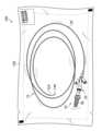
図5は、本発明の実施形態に係るカテーテルパッケージ100の全体図であり、カテーテル装置10の出荷時の形態が示されている。 <Shipping form>
FIG. 5 is an overall view of a
図5に示すように、本例のカテーテルパッケージ100は、カテーテル装置10とパッケージ本体102と有しており、パッケージ本体102にカテーテル装置10が収容されている。As shown in FIG. 5, the
パッケージ本体102は、外部空間に対して遮断された収容部が内部に形成されている。また、パッケージ本体102は、透明の材料によって構成されている。The
カテーテル装置10は、湾曲状の先端部14Aの全長をチューブ20の先端開口部12Aから突出させた突出状態でパッケージ本体102に収容される。この形態が、カテーテル装置10の出荷時の形態である。The
このように本例のカテーテル装置10は、出荷時におけるカテーテル本体12とスライドワイヤ14との相対位置を上記の突出状態を可能とする位置に規定することができるので、出荷時において先端部14Aの曲げ癖がチューブ20に転写されることを防止することができる。これにより、カテーテル本体12に曲げ癖がつくことを防止することができる。In this way, the
<臨床使用時の形態>
臨床使用時においては、図5のパッケージ本体102を開封してカテーテル装置10をパッケージ本体102から取り出す。このとき、先端部14Aは突出状態にあるので、ハンドル58でスライドワイヤ14を基端開口部12Bに向かう方向に移動させて突出状態から非突出状態へ移行させる。この形態が、カテーテル装置10の臨床使用時の形態である。 <Form for clinical use>
In clinical use, the
このように本例のカテーテル装置10は、臨床使用時におけるカテーテル本体12とスライドワイヤ14との相対位置を上記の非突出状態を可能とする位置に規定することができる。これにより、臨床使用時において、スライドワイヤ14の先端部14Aが体腔内の側に突出することを防止することができる。In this way, the
以上説明したように、第1実施形態のカテーテル装置10によれば、カテーテル本体12は、突出状態と非突出状態とに分別するワイヤ状態分別部15を有し、ワイヤ状態分別部15は、突出状態から非突出状態への移行を許容し、かつ、非突出状態から突出状態への移行を阻止する許容阻止部材としてのストッパ16を有しているので、出荷時及び臨床使用時におけるカテーテル本体12とスライドワイヤ14との好適な相対位置を規定することが可能となる。As described above, according to the first embodiment of the
次に、図6に示したフローチャートを参照しながら、本例のカテーテル装置10を、DB-ERCP(double balloon endoscopic retrograde cholangiopancreatography)に使用した場合の施術例の一例について説明する。Next, with reference to the flowchart shown in FIG. 6, we will explain an example of a procedure in which the
まず、ステップ(S)200において、パッケージ本体102を開封して、パッケージ本体102からカテーテル装置10を取り出す。First, in step (S) 200, the
このとき、スライドワイヤ14の先端部14Aは突出状態にあるので、S210において、ハンドル58でスライドワイヤ14を基端開口部12Bに向かう方向に移動させて突出状態から非突出状態へ移行させる。なお、ハンドル58を操作する術者は、図3に示した段差部18Bが段差部16Bを乗り越えることきに感じる操作感で突出状態から非突出状態へ移行したことを確認することができる。At this time, the
次に、S220において、直視鏡であるダブルバルーン内視鏡を使用し、このダブルバルーン内視鏡の鉗子口から、チューブ20の先端開口部12Aを先頭にしてチューブ20をダブルバルーン内視鏡の挿入部に挿入する。このとき、スライドワイヤ14の先端部14Aは、先端開口部12Aから突出していないので、チューブ20を挿入部に円滑に挿入することができる。Next, in S220, a double-balloon endoscope, which is a direct endoscope, is used, and the
次に、S230において、バルーンを適宜膨縮させながら、ダブルバルーン内視鏡の挿入部の先端部を口から十二指腸の乳頭の付近まで挿入する。この挿入操作は、挿入部の先端部に設けられた撮像部から送られてくる体腔画像をモニタで観察しながら行う。Next, in S230, the tip of the insertion section of the double-balloon endoscope is inserted from the mouth to near the duodenal papilla while the balloon is inflated and deflated appropriately. This insertion operation is performed while observing on a monitor the body cavity image sent from the imaging section provided at the tip of the insertion section.
次に、S240において、挿入部の先端部からチューブ20の先端部20Aを突出させる。このとき、先端部20Aは、先端部20Aの内部に収容されているスライドワイヤ14の湾曲状の先端部14Aの形状に沿って湾曲状に弾性変形している。Next, in S240, the
次に、S250において、モニタに表示される乳頭とチューブ20の先端部20Aの画像を見ながら、先端部20Aの向きが乳頭に向くように、カテーテル装置10のハンドル58を操作する。すなわち、ハンドル58を回転させた場合には、スライドワイヤ14が軸線14C周りに回転するので、チューブ20の湾曲した先端部20Aを、軸線14Cを中心に回転させることができる。また、ハンドル58を引き寄せたり押し込んだりした場合には、スライドワイヤ14が軸線14Cに沿って移動するので、チューブ20の先端部20Aの湾曲角度を変更することができる。このような操作を適宜実施して先端部20Aの向きを乳頭に向ける。Next, in S250, while viewing the image of the nipple and the
次に、S260において、チューブ20の先端部20Aを乳頭に挿入する。Next, in S260, the
次に、S270において、チューブ20の先端部20Aを乳頭に挿入した状態で、ハンドル58を回転操作してチューブ20の先端部20Aを回転させながら、胆管の向きを探り、先端部20Aの向きを胆管の向きに合わせる。この後、図2に示した制動部56によってスライドワイヤ14を動作不能に固定して先端部20Aの向きを固定する。Next, in S270, with the
次に、S280において、図2に示した三叉管22の通路44からガイドワイヤを挿入し、ガイドワイヤの先端部をチューブ20の先端開口部12Aから突出させて胆管に挿入する。Next, in S280, a guidewire is inserted through the
次に、S290において、必要に応じて、ガイドワイヤをガイドにしてチューブ20を胆管の奥側に挿入する。Next, in S290, the
次に、S300において、必要に応じて、図2に示した三叉管22の通路40から造影剤を送り込み、この造影剤をチューブ20の先端開口部12Aから胆管内に注入する。Next, in S300, if necessary, contrast medium is fed through the
次に、S310において、必要に応じて、ガイドワイヤをガイドにして、バルーン又はステント等の他のデバイスを胆管内に挿入して患部の処置を行う。以上が、本例のカテーテル装置10を使用した施術例の一例である。Next, in S310, if necessary, a balloon or other device such as a stent is inserted into the bile duct using the guidewire as a guide to treat the affected area. The above is an example of a procedure using the
ここで、上記のDB-ERCPと通常症例のERCPとの施術手法の相違点について簡単に説明する。Here, we will briefly explain the differences in the treatment methods between the above DB-ERCP and ERCP for normal cases.
ERCPは、口から十二指腸まで十二指腸鏡を挿入し、十二指腸鏡の先端部からチューブの先端部を導出する。次に、十二指腸鏡の先端部に設けられている処置具起立台を操作してチューブの先端部の向きを乳頭の向きに合わせた後、チューブ20の先端部を、乳頭を介して胆管内に挿入する(以下、「カニュレーション」と言う。)。In ERCP, a duodenoscope is inserted from the mouth to the duodenum, and the tip of a tube is drawn out from the tip of the duodenoscope. Next, the treatment tool stand provided at the tip of the duodenoscope is operated to align the tip of the tube with the papilla, and then the tip of the
これに対し、DB-ERCPは、十二指腸鏡を乳頭まで挿入することができないため、十二指腸鏡に代えてダブルバルーン内視鏡等の直視鏡を使用するが、直視鏡は、処置具起立台を備えていない。また、乳頭の向きは、特に術後腸管であるが故にまちまちである。このような事情により、DB-ERCPでは、チューブの先端部の向きを乳頭の向きに合わせることが非常に難しく、カニュレーションを容易に行うことができない場合がある。In contrast, in DB-ERCP, a duodenoscope cannot be inserted all the way to the papilla, so a direct endoscope such as a double-balloon endoscope is used instead of a duodenoscope, but a direct endoscope does not have a treatment instrument stand. Also, the orientation of the papilla varies, especially in the postoperative intestine. For these reasons, in DB-ERCP, it is very difficult to align the tip of the tube with the orientation of the papilla, and cannulation cannot be easily performed.
そこで、本例のカテーテル装置10をDB-ERCPに使用した場合、本例のカテーテル装置10は、ハンドル58の回転操作と押し引き操作とによってチューブ20の先端部20Aの向きを自在に調整することができるので、チューブ20の先端部20Aの向きを、乳頭の向きに容易に合わせることができる。これにより、カニュレーションを容易に行うことができる。When the
以下、本発明に係るカテーテル装置のいくつかの実施形態について説明する。The following describes several embodiments of the catheter device according to the present invention.
<第2実施形態>
図7は、第2実施形態のカテーテル装置110の要部拡大断面図であり、移動体112とストッパ114とが図示されている。第2実施形態のカテーテル装置110と、図1から図5に示した第1実施形態のカテーテル装置10との相違点は、図7に示した移動体112とストッパ114の形状であり、他の部分は同一であるので説明は省略する。 Second Embodiment
Fig. 7 is an enlarged cross-sectional view of a main portion of a
図7に示す移動体112は、その内部にスライドワイヤ14が挿通配置されてスライドワイヤ14に固定されている。この移動体112は、基端開口部12Bに向かう方向に向けて外径が小さくなる円錐台形状に構成され、その外周面が円錐台面112Aとして形成されている。また、移動体112の先端側の面は、軸線14Cに垂直な垂直面112Bとして形成されている。The
一方、ストッパ114は、段差部114Aを有している。この段差部114Aは、移動体112が基端開口部12Bに向かう方向に移動する場合に、移動体112の円錐台面112Aに当接して移動体112が乗り越え可能な円錐台面114Bを有している。また、段差部114Aは、移動体112が先端開口部12Aに向かう方向に移動する場合に、移動体112の垂直面112Bが当接され移動体112の移動を規制する垂直面114Cを有している。ここで、円錐台面114Bは、ストッパ側乗り越え面として機能し、垂直面114Cは、規制面として機能する。On the other hand, the
第2実施形態のカテーテル装置110によれば、ストッパ114は、スライドワイヤ14が先端開口部12Aから基端開口部12Bに向かう方向に移動する場合には、移動体112の移動を許容して、突出状態から非突出状態へ移行することを可能とする。また、ストッパ114は、スライドワイヤ14が基端開口部12Bから先端開口部12Aに向かう方向に移動する場合には、移動体112の移動を規制して、非突出状態から突出状態へ移行することを不能にする。これにより、第2実施形態のカテーテル装置110は、第1実施形態のカテーテル装置10と同様に、カテーテル本体12に曲げ癖がつくことを防止することができ、かつ、出荷時及び臨床使用時におけるカテーテル本体とワイヤとの好適な相対位置を規定することが可能となる。According to the
<第3実施形態>
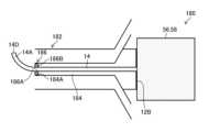
図8は、第3実施形態のカテーテル装置120の概略断面図であり、マルチルーメンチューブ124を含むチューブ122が図示されている。 Third Embodiment
FIG. 8 is a schematic cross-sectional view of a third embodiment of a
図8に示すように、マルチルーメンチューブ124は、ワイヤ挿通路126と、液体供給口42に連通された液体通路128と、ガイドワイヤ挿通口46に連通されたガイドワイヤ挿通路130とを有している。As shown in FIG. 8, the
また、図8に示すカテーテル本体132は、長手方向Aにおいて、先端開口部12A(図2参照)の側よりも基端開口部12Bの側にストッパ16を有し、このストッパ16に対して基端開口部12Bの側に上記の液体供給口42が形成されている。そして、液体供給口42からストッパ16までの範囲F1が上記のマルチルーメンチューブ124によって構成されている。The
このように構成されたカテーテル装置120によれば、液体供給口42から液体通路128に供給された造影剤は、液体通路128の先端開口部128Aから、シングルルーメンチューブによって構成されているチューブ122に円滑に流れる。このように、液体供給口42からストッパ16までの範囲F1をマルチルーメンチューブ124によって構成することにより、図2で示した逆流防止用の止水弁39を用いることなく、基端開口部12Bの側への造影剤の逆流を防止することができる。According to the
なお、チューブ122におけるマルチルーメンチューブ124の範囲は、範囲F1に限定されるものではなく、少なくとも範囲F1がマルチルーメンチューブ124によって構成されていればよいので、範囲F1を超えた範囲をマルチルーメンチューブ124によって構成してもよい。例えば、チューブ122の全長をマルチルーメンチューブ124によって構成してもよい。The range of the
また、図8に示したマルチルーメンチューブ124は、液体通路128とガイドワイヤ挿通路130とが各々独立して構成されたものであるが、液体通路128とガイドワイヤ挿通路130とが1本の通路として構成されたマルチルーメンチューブとしてもよい。In addition, the
<第4実施形態>
図9は、第4実施形態のカテーテル装置140の概略断面図であり、マルチルーメンチューブ144を含むチューブ142が図示されている。第4実施形態のカテーテル装置140と、図8に示した第3実施形態のカテーテル装置120との相違点は、図9に示したストッパ16が基端開口部12Bの側よりも先端開口部12Aの側に配置された点にある。 Fourth Embodiment
Fig. 9 is a schematic cross-sectional view of a
図9に示すように、マルチルーメンチューブ144は、ワイヤ挿通路146と、液体供給口42に連通された液体通路148と、ガイドワイヤ挿通口46に連通されたガイドワイヤ挿通路150とを有している。As shown in FIG. 9, the
また、図9に示すカテーテル本体152は、ストッパ16に対して基端開口部12Bの側に上記の液体供給口42が形成されている。そして、液体供給口42からストッパ16までの範囲F2がマルチルーメンチューブ144によって構成されている。The
このように構成されたカテーテル装置140によれば、液体供給口42から液体通路148に供給された造影剤は、液体通路148の先端開口部148Aから、シングルルーメンチューブによって構成されているチューブ142に円滑に流れる。このように、液体供給口42からストッパ16までの範囲F2をマルチルーメンチューブ144によって構成することにより、図2で示した逆流防止用の止水弁39を用いることなく、基端開口部12Bの側への造影剤の逆流を防止することができる。According to the
なお、チューブ142におけるマルチルーメンチューブ144の範囲は、範囲F2に限定されるものではなく、少なくとも範囲F2がマルチルーメンチューブ144によって構成されていればよいので、範囲F2を超えた範囲をマルチルーメンチューブ144によって構成してもよい。例えば、チューブ142の全長をマルチルーメンチューブ144によって構成してもよい。 The range of the
<第5実施形態>
図10は、第5実施形態のカテーテル装置160の概略断面図であり、マルチルーメンチューブ164を含むチューブ162が図示されている。第5実施形態のカテーテル装置160と、図8に示した第3実施形態のカテーテル装置120との相違点は、図10に示したストッパ16が基端開口部12Bと先端開口部12Aとの間の中腹側に配置された点にある。 Fifth Embodiment
Fig. 10 is a schematic cross-sectional view of a
図10に示すように、マルチルーメンチューブ164は、ワイヤ挿通路166と、液体供給口42に連通された液体通路168と、ガイドワイヤ挿通口46に連通されたガイドワイヤ挿通路170とを有している。As shown in FIG. 10, the
また、図10に示すカテーテル本体172は、ストッパ16に対して基端開口部12Bの側に上記の液体供給口42が形成されている。そして、液体供給口42からストッパ16までの範囲F3が上記のマルチルーメンチューブ164によって構成されている。The
このように構成されたカテーテル装置160によれば、液体供給口42から液体通路168に供給された造影剤は、液体通路168の先端開口部168Aから、シングルルーメンチューブによって構成されているチューブ162に円滑に流れる。このように、液体供給口42からストッパ16までの範囲F3をマルチルーメンチューブ164によって構成することにより、図2で示した逆流防止用の止水弁39を用いることなく、基端開口部12Bの側への造影剤の逆流を防止することができる。According to the
なお、チューブ162におけるマルチルーメンチューブ164の範囲は、範囲F3に限定されるものではなく、少なくとも範囲F3がマルチルーメンチューブ164によって構成されていればよいので、範囲F3を超えた範囲をマルチルーメンチューブ164によって構成してもよい。例えば、チューブ162の全長をマルチルーメンチューブ164によって構成してもよい。The range of the
また、図10に示したマルチルーメンチューブ164は、液体通路168とガイドワイヤ挿通路170とが各々独立して構成されたものであるが、これに限定されるものではなく、液体通路168とガイドワイヤ挿通路170とが1本の通路として構成されたマルチルーメンチューブとしてもよい。In addition, the
以上説明した第1乃至第5実施形態では、ストッパと移動体とがそれぞれワイヤ挿通路内に設けられたカテーテル装置を例示したが、本発明のカテーテル装置は、これらの実施形態に限定されるものではない。例えば、ストッパを備えたアダプタであって、カテーテル本体の一部を構成するアダプタをカテーテル本体の外側に取り付け、このアダプタにワイヤを配設し、アダプタ内のストッパによって移動体の移動を許容又は規制するようにしてもよい。つまり、ストッパは、カテーテル本体に設けられていればよい。In the first to fifth embodiments described above, a catheter device in which a stopper and a moving body are provided in the wire insertion passage have been exemplified, but the catheter device of the present invention is not limited to these embodiments. For example, an adapter with a stopper may be attached to the outside of the catheter body, forming part of the catheter body, and a wire may be arranged in this adapter, and the movement of the moving body may be permitted or restricted by the stopper in the adapter. In other words, it is sufficient that the stopper is provided in the catheter body.
また、図1及び図2に示した第1実施形態では、チューブ20と、三叉管22と、連結管26とによって構成したカテーテル本体12を例示したが、これに限定されるものではなく、例えば、チューブ20のみでカテーテル本体を構成してもよい。この場合、チューブ20にストッパ16を設ければよい。In the first embodiment shown in Figs. 1 and 2, the
<第6実施形態>
図11は、第6実施形態のカテーテル装置180の概略断面図である。 Sixth Embodiment
FIG. 11 is a schematic cross-sectional view of a
図11に示すカテーテル装置180は、チューブ182がマルチルーメンチューブによって構成されている。そして、このマルチルーメンチューブの中のワイヤ挿通路184の先端開口部184Aに、許容阻止部材として機能する弁部材186が取り付けられている。The
弁部材186は、ゴム等の弾性部材によって構成された弾性弁部材であり、その外周部を先端開口部184Aの内壁に固着することにより先端開口部184Aに装着される。また、弁部材186の中央部には、スライドワイヤ14を挿通可能な挿通孔186Aが形成されている。The
第6実施形態によれば、図11に示すように、出荷時においては、スライドワイヤ14の先端部14Aを弁部材186の挿通孔186Aから突出させる。これにより、先端部14Aの曲げ癖がチューブ182に転写されることを防止することができるので、カテーテル本体に曲げ癖がつくことを防止することができる。また、図12に示すように、臨床使用時においては、先端部14Aをワイヤ挿通路184内に収容する。これにより、挿通孔186Aが閉塞するので、先端部14Aが体腔内の側に突出することを防止することができる。According to the sixth embodiment, as shown in FIG. 11, at the time of shipment, the
なお、この場合、ワイヤ挿通路184の直径を、スライドワイヤ14の直径よりも大きく形成することが好ましい。そうすると、先端部14Aがワイヤ挿通路184に収容された場合、先端14Dと挿通孔186Aとの相対位置が弁部材186の直径方向にずれるので、先端14Dが挿通孔186Aに再挿入されることを阻止できる。これにより、上記の突出を確実に防止することができる。In this case, it is preferable to form the diameter of the
以上、本発明の実施形態について説明したが、本発明は、以上の例には限定されず、本発明の要旨を逸脱しない範囲において、各種の改良や変形を行ってもよいのはもちろんである。例えば、図5に示したパッケージ本体102に、第2乃至第6実施形態のカテーテル装置110、120、140、160、180を収容することが可能である。Although the embodiments of the present invention have been described above, the present invention is not limited to the above examples, and various improvements and modifications may be made without departing from the spirit of the present invention. For example, the
以下、本発明とは異なるカテーテル装置の例について説明する。Below, we will explain an example of a catheter device that differs from the present invention.
本発明は、許容阻止部材によって非突出状態から突出状態への移行を阻止したが、臨床使用時において、先端開口部12Aから先端部14Aを突出させてもよい場合には、非突出状態から突出状態への移行を許容してもよい。 In the present invention, the transition from the non-protruding state to the protruding state is prevented by the blocking member, but in cases where it is acceptable for the
この場合、例えば、図7に示したストッパ114において、垂直面114Cの形状を円錐台面に形成し、スライドワイヤ14が基端開口部12Bから先端開口部12Aに向かう方向に移動する場合に移動体112の移動を許容する構成とすればよい。In this case, for example, in the
10 カテーテル装置
12 カテーテル本体
12A 先端開口部
12B 基端開口部
14 スライドワイヤ
14A 先端部
14B 基端部
14C 軸線
14D 先端
15 ワイヤ状態分別部
16 ストッパ
16A 挿通孔
16B 段差部
16C 垂直面
16D 垂直面
18 移動体
18A 挿通孔
18B 段差部
18C 円錐台面
18D 垂直面
20 チューブ
20A 先端部
22 三叉管
24 第1管
24A 雄ネジ
26 連結管
26B フランジ
26C 円筒部
26D 雌ネジ
28 通路
30 主管
32 第2管
34 第3管
36 通路
38 通路
38A 内壁
39 止水弁
40 通路
42 液体供給口
44 通路
46 ガイドワイヤ挿通口
48 通路
50 先端部
52 基端開口部
54 ナット
54A 雌ネジ
54B フランジ
56 制動部
58 ハンドル
60 ガイド管
60A 先端部
60B 基端部
62 ブレーキパッド
62A 挿通孔
64 締結部材
66 雄ネジ部
68 ノブ部
100 カテーテルパッケージ
102 パッケージ本体
110 カテーテル装置
112 移動体
112A 円錐台面
112B 垂直面
114 ストッパ
114A 段差部
114B 円錐台面
114C 垂直面
120 カテーテル装置
122 チューブ
124 マルチルーメンチューブ
126 ワイヤ挿通路
128 液体通路
130 ガイドワイヤ挿通路
132 カテーテル本体
140 カテーテル装置
142 チューブ
144 マルチルーメンチューブ
146 ワイヤ挿通路
148 液体通路
150 ガイドワイヤ挿通路
152 カテーテル本体
160 カテーテル装置
162 チューブ
164 マルチルーメンチューブ
166 ワイヤ挿通路
168 液体通路
170 ガイドワイヤ挿通路
172 カテーテル本体
180 カテーテル装置
182 チューブ
184A 先端開口部
186 弁部材
186A 挿通孔
R1 突出領域
R2 非突出領域10
110
Claims (15)
Translated fromJapanese前記カテーテル本体よりも高い剛性を備えて前記ワイヤ挿通路に挿入され、先端部と基端部とを有し、前記先端部が湾曲状に形成されたワイヤと、
を備えたカテーテル装置であって、
前記カテーテル本体は、前記カテーテル装置の使用前において前記ワイヤの前記先端部が前記先端開口部から突出した突出状態と、前記カテーテル本体を前記体腔内に挿入する時点において前記ワイヤの前記先端部が前記先端開口部から突出しない非突出状態とに分別するワイヤ状態分別部を有し、
前記ワイヤ状態分別部は、前記突出状態から前記非突出状態への移行を許容し、かつ、前記非突出状態から前記突出状態への移行を阻止する許容阻止部材を有する、
カテーテル装置。 a catheter body having a distal end opening and a proximal end opening, the catheter body being flexible and adapted to be inserted into a body cavity with the distal end opening at the leading edge, the catheter body being provided with a wire insertion passage;
a wire having a rigidity higher than that of the catheter body, the wire being inserted into the wire passage, the wire having a distal end and a proximal end, the distal end being curved;
A catheter device comprising:
the catheter body has a wire state sorting section that sorts the wire into a protruding state in which the tip portion of the wire protrudes from the tip opening before use of the catheter device and a non-protruding state in which the tip portion of the wire does not protrude from the tip opening atthe time when the catheter body is inserted into the body cavity ,
the wire-state discrimination unit has an allowance/blocking member that allows a transition from the protruding state to the non-protruding state and blocks a transition from the non-protruding state to the protruding state.
Catheter device.
前記許容阻止部材は、前記移動体の移動を許容又は規制するストッパを有し、
前記ストッパは、前記ワイヤが前記先端開口部から前記基端開口部に向かう方向に移動する場合には前記移動体の移動を許容して、前記突出状態から前記非突出状態へ移行することを可能とし、かつ、前記ワイヤが前記基端開口部から前記先端開口部に向かう方向に移動する場合には前記移動体の移動を規制して、前記非突出状態から前記突出状態へ移行することを不能にする、
請求項1に記載のカテーテル装置。 a movable body provided so as to be movable integrally with the wire;
the blocking member has a stopper that blocks or allows the movement of the movable body,
the stopper permits movement of the movable body when the wire moves in a direction from the tip opening toward the base opening, thereby enabling the wire to transition from the protruding state to the non-protruding state, and restricts movement of the movable body when the wire moves in a direction from the base opening toward the tip opening, thereby disabling the wire from transitioning from the non-protruding state to the protruding state.
The catheter device of claim 1.
前記ストッパは、前記ワイヤ挿通路内に設けられる、
請求項2に記載のカテーテル装置。 The movable body is provided so as to be movable integrally with the wire through the wire insertion passage,
The stopper is provided in the wire insertion passage.
The catheter device of claim 2.
前記移動体は、前記基端開口部に向かう方向に移動する場合に前記段差部に当接して前記段差部を乗り越え可能な移動体側乗り越え面と、前記先端開口部に向かう方向に移動する場合に前記段差部に当接して移動が規制される被規制面とを有する、
請求項3に記載のカテーテル装置。 The stopper has a step portion provided in the wire insertion passage,
The movable body has a movable body side climbing surface that can climb over the step portion by contacting the step portion when moving in a direction toward the base end opening, and a restricted surface that abuts against the step portion and is restricted in movement when moving in a direction toward the tip end opening.
The catheter device of claim 3.
前記段差部は、前記移動体が前記基端開口部に向かう方向に移動する場合に前記移動体に当接して前記移動体が乗り越え可能なストッパ側乗り越え面と、前記移動体が前記先端開口部に向かう方向に移動する場合に前記移動体が当接され前記移動体の移動を規制する規制面とを有する、
請求項3に記載のカテーテル装置。 The stopper has a step portion provided in the wire insertion passage,
The step portion has a stopper-side climbing surface that comes into contact with the movable body when the movable body moves in a direction toward the base end opening and that the movable body can climb over, and a restricting surface that comes into contact with the movable body when the movable body moves in a direction toward the tip end opening and restricts the movement of the movable body.
The catheter device of claim 3.
請求項2から5のいずれか1項に記載のカテーテル装置。 At least one of the moving body and the stopper is made of an elastic member.
A catheter device according to any one of claims 2 to 5.
前記液体供給口と前記基端開口部との間の前記ワイヤ挿通路には、前記液体が前記基端開口部から外部に漏れるのを防止する止水弁が設けられる、
請求項1から6のいずれか1項に記載のカテーテル装置。 the catheter body has an outer circumferential surface, and a liquid supply port for supplying liquid to the wire insertion passage is formed on the outer circumferential surface between the tip opening and the base opening,
a water stop valve is provided in the wire insertion passage between the liquid supply port and the base end opening to prevent the liquid from leaking to the outside through the base end opening;
A catheter device according to any one of claims 1 to 6.
前記カテーテル本体は外周面を有し、前記外周面には、前記液体挿通路に液体を供給する液体供給口が前記ストッパに対して前記基端開口部の側に形成され、
前記カテーテル本体の長手方向において、前記液体供給口から前記ストッパまでの範囲が少なくとも前記マルチルーメンチューブとして構成される、
請求項2から6のいずれか1項に記載のカテーテル装置。 the catheter body includes a multi-lumen tube having the wire passage and a liquid passage;
the catheter body has an outer circumferential surface, and a liquid supply port for supplying liquid to the liquid insertion passage is formed on the outer circumferential surface on the side of the base end opening relative to the stopper;
In the longitudinal direction of the catheter body, at least a range from the liquid supply port to the stopper is configured as the multi-lumen tube.
A catheter device according to any one of claims 2 to 6.
請求項8に記載のカテーテル装置。 the stopper is provided closer to the base end opening side than to the tip end opening side in the longitudinal direction of the catheter body;
The catheter device of claim 8.
請求項8に記載のカテーテル装置。 the stopper is provided closer to the tip opening side than to the base opening side in the longitudinal direction of the catheter body;
The catheter device of claim 8.
請求項8に記載のカテーテル装置。 The stopper is provided midway between the base end opening and the tip end opening in the longitudinal direction of the catheter body.
The catheter device of claim 8.
前記弾性弁部材には、前記ワイヤを挿通可能な挿通孔が設けられ、
前記弾性弁部材は、前記挿通孔に前記ワイヤが配置されない場合には前記挿通孔を閉塞する、
請求項1に記載のカテーテル装置。 The blocking member has an elastic valve member provided in the wire insertion passage,
The elastic valve member is provided with an insertion hole through which the wire can be inserted,
the elastic valve member closes the insertion hole when the wire is not disposed in the insertion hole;
The catheter device of claim 1.
前記ワイヤ操作部は、前記基端開口部から外部に延設された前記ワイヤの基端部に接続される、
請求項1から12のいずれか1項に記載のカテーテル装置。 A wire operating unit that operates the wire in a wire axial direction and a direction around the wire axial direction,
The wire operating section is connected to a proximal end of the wire extending from the proximal end opening to the outside.
A catheter device according to any one of claims 1 to 12.
前記固定部材は、前記基端開口部から外部に延設された前記ワイヤの基端部に設けられる、
請求項1から13のいずれか1項に記載のカテーテル装置。 a fixing member for temporarily fixing a relative position of the wire with respect to the catheter body;
The fixing member is provided at a proximal end of the wire extending from the proximal end opening to the outside.
A catheter device according to any one of claims 1 to 13.
前記カテーテル装置は、前記ワイヤの前記先端部を前記先端開口部から突出させた突出状態で前記パッケージ本体に収容される、カテーテルパッケージ。A catheter package comprising the catheter deviceaccording to any one of claims 1 to 14 and a package body capable of housing the catheter device,
The catheter device is accommodated in the package body in a protruding state with the tip of the wire protruding from the tip opening.
Priority Applications (3)
| Application Number | Priority Date | Filing Date | Title |
|---|---|---|---|
| JP2020122666AJP7482709B2 (en) | 2020-07-17 | 2020-07-17 | Catheter device and catheter package |
| US17/354,878US20220016390A1 (en) | 2020-07-17 | 2021-06-22 | Catheter device and catheter package |
| EP21184271.1AEP3950035A3 (en) | 2020-07-17 | 2021-07-07 | Catheter device and catheter package |
Applications Claiming Priority (1)
| Application Number | Priority Date | Filing Date | Title |
|---|---|---|---|
| JP2020122666AJP7482709B2 (en) | 2020-07-17 | 2020-07-17 | Catheter device and catheter package |
Publications (3)
| Publication Number | Publication Date |
|---|---|
| JP2022019086A JP2022019086A (en) | 2022-01-27 |
| JP2022019086A5 JP2022019086A5 (en) | 2022-08-03 |
| JP7482709B2true JP7482709B2 (en) | 2024-05-14 |
Family
ID=76829460
Family Applications (1)
| Application Number | Title | Priority Date | Filing Date |
|---|---|---|---|
| JP2020122666AActiveJP7482709B2 (en) | 2020-07-17 | 2020-07-17 | Catheter device and catheter package |
Country Status (3)
| Country | Link |
|---|---|
| US (1) | US20220016390A1 (en) |
| EP (1) | EP3950035A3 (en) |
| JP (1) | JP7482709B2 (en) |
Citations (6)
| Publication number | Priority date | Publication date | Assignee | Title |
|---|---|---|---|---|
| JP2004518468A (en) | 2001-01-29 | 2004-06-24 | ビー.ブラウン メディカル,インコーポレイティド | Method of holding tip protector on needle with curved tip |
| JP2006141778A (en) | 2004-11-22 | 2006-06-08 | Tonokura Ika Kogyo Kk | Guide catheter set body for balloon catheter |
| JP2008125912A (en) | 2006-11-22 | 2008-06-05 | Terumo Corp | Valve body and medical device |
| JP2011072680A (en) | 2009-09-30 | 2011-04-14 | Terumo Corp | Image diagnosis catheter |
| JP2012519057A (en) | 2009-03-02 | 2012-08-23 | ベクトン・ディキンソン・アンド・カンパニー | Bidirectional cannula feature capture mechanism |
| JP2020516367A (en) | 2017-04-14 | 2020-06-11 | アクセス サイエンティフィック, エルエルシーAccess Scientific, Llc | Vascular access device |
Family Cites Families (9)
| Publication number | Priority date | Publication date | Assignee | Title |
|---|---|---|---|---|
| DE3150052C2 (en)* | 1981-12-17 | 1985-02-21 | Sterimed Gesellschaft für medizinischen Bedarf mbH, 6600 Saarbrücken | Catheter for catheterizing central veins |
| JPH0824664B2 (en) | 1986-10-31 | 1996-03-13 | オリンパス光学工業株式会社 | Medical flexible tube bending assembly |
| AU654464B3 (en)* | 1994-04-20 | 1994-11-03 | Noble House Group Pty Ltd | Protective sheath |
| US10327743B2 (en)* | 1999-04-09 | 2019-06-25 | Evalve, Inc. | Device and methods for endoscopic annuloplasty |
| US6436090B1 (en)* | 2000-12-21 | 2002-08-20 | Advanced Cardiovascular Systems, Inc. | Multi lumen catheter shaft |
| EP1907042B1 (en)* | 2005-07-06 | 2009-03-11 | Vascular Pathways Inc. | Intravenous catheter insertion device and method of use |
| US9399120B2 (en)* | 2009-03-02 | 2016-07-26 | Becton, Dickinson And Company | Bi-directional cannula feature capture mechanism |
| US8932258B2 (en)* | 2010-05-14 | 2015-01-13 | C. R. Bard, Inc. | Catheter placement device and method |
| JP5508479B2 (en)* | 2012-07-05 | 2014-05-28 | 寛治 井上 | Catheter-type therapeutic / diagnostic instrument with stylet and catheter tube using stylet |
- 2020
- 2020-07-17JPJP2020122666Apatent/JP7482709B2/enactiveActive
- 2021
- 2021-06-22USUS17/354,878patent/US20220016390A1/ennot_activeAbandoned
- 2021-07-07EPEP21184271.1Apatent/EP3950035A3/enactivePending
Patent Citations (6)
| Publication number | Priority date | Publication date | Assignee | Title |
|---|---|---|---|---|
| JP2004518468A (en) | 2001-01-29 | 2004-06-24 | ビー.ブラウン メディカル,インコーポレイティド | Method of holding tip protector on needle with curved tip |
| JP2006141778A (en) | 2004-11-22 | 2006-06-08 | Tonokura Ika Kogyo Kk | Guide catheter set body for balloon catheter |
| JP2008125912A (en) | 2006-11-22 | 2008-06-05 | Terumo Corp | Valve body and medical device |
| JP2012519057A (en) | 2009-03-02 | 2012-08-23 | ベクトン・ディキンソン・アンド・カンパニー | Bidirectional cannula feature capture mechanism |
| JP2011072680A (en) | 2009-09-30 | 2011-04-14 | Terumo Corp | Image diagnosis catheter |
| JP2020516367A (en) | 2017-04-14 | 2020-06-11 | アクセス サイエンティフィック, エルエルシーAccess Scientific, Llc | Vascular access device |
Also Published As
| Publication number | Publication date |
|---|---|
| EP3950035A3 (en) | 2022-05-04 |
| US20220016390A1 (en) | 2022-01-20 |
| EP3950035A2 (en) | 2022-02-09 |
| JP2022019086A (en) | 2022-01-27 |
Similar Documents
| Publication | Publication Date | Title |
|---|---|---|
| EP3943140B1 (en) | Female catheter locator tip | |
| US5897497A (en) | Guiding catheter introducer assembly | |
| US20230166073A1 (en) | Intermittent urinary catheter assembly | |
| JP3448228B2 (en) | Endoscope insertion guide tube | |
| US5836951A (en) | Balloon dilation catheter | |
| JP2005312976A (en) | Wire guide apparatus | |
| JP3081778B2 (en) | catheter | |
| US20050203543A1 (en) | Surgical guide valve | |
| EP1808077A1 (en) | Treatment means introduction member, stent delivery catheter, and pipeline system | |
| JPH06105798A (en) | Catheter tube | |
| US20070049801A1 (en) | Endoscope accessory | |
| US6723070B1 (en) | Balloon catheter | |
| JPH06343702A (en) | Catheter | |
| US20220088354A1 (en) | Balloon catheter | |
| JP7482709B2 (en) | Catheter device and catheter package | |
| JP3231080B2 (en) | Catheter tube | |
| JP2010273988A (en) | Catheter | |
| JP3098062B2 (en) | Catheter tube | |
| JPH06292678A (en) | Insertion assisting means for medical purpose | |
| JP2542591Y2 (en) | Catheter tube | |
| JP7712122B2 (en) | Catheter System | |
| JP2017042203A (en) | Balloon catheter | |
| JP7024843B2 (en) | Medical connector | |
| JPH0576480A (en) | Catheter tube | |
| JP2023146449A (en) | Medical appliance and introducer |
Legal Events
| Date | Code | Title | Description |
|---|---|---|---|
| A521 | Request for written amendment filed | Free format text:JAPANESE INTERMEDIATE CODE: A523 Effective date:20220726 | |
| A621 | Written request for application examination | Free format text:JAPANESE INTERMEDIATE CODE: A621 Effective date:20220726 | |
| A977 | Report on retrieval | Free format text:JAPANESE INTERMEDIATE CODE: A971007 Effective date:20230531 | |
| A131 | Notification of reasons for refusal | Free format text:JAPANESE INTERMEDIATE CODE: A131 Effective date:20230627 | |
| A521 | Request for written amendment filed | Free format text:JAPANESE INTERMEDIATE CODE: A523 Effective date:20230821 | |
| A131 | Notification of reasons for refusal | Free format text:JAPANESE INTERMEDIATE CODE: A131 Effective date:20231205 | |
| A521 | Request for written amendment filed | Free format text:JAPANESE INTERMEDIATE CODE: A523 Effective date:20240125 | |
| TRDD | Decision of grant or rejection written | ||
| A01 | Written decision to grant a patent or to grant a registration (utility model) | Free format text:JAPANESE INTERMEDIATE CODE: A01 Effective date:20240405 | |
| A61 | First payment of annual fees (during grant procedure) | Free format text:JAPANESE INTERMEDIATE CODE: A61 Effective date:20240430 | |
| R150 | Certificate of patent or registration of utility model | Ref document number:7482709 Country of ref document:JP Free format text:JAPANESE INTERMEDIATE CODE: R150 |