JP7477515B2 - Pumping apparatus and method for a substrate processing chamber - Patents.com - Google Patents
Pumping apparatus and method for a substrate processing chamber - Patents.comDownload PDFInfo
- Publication number
- JP7477515B2 JP7477515B2JP2021538731AJP2021538731AJP7477515B2JP 7477515 B2JP7477515 B2JP 7477515B2JP 2021538731 AJP2021538731 AJP 2021538731AJP 2021538731 AJP2021538731 AJP 2021538731AJP 7477515 B2JP7477515 B2JP 7477515B2
- Authority
- JP
- Japan
- Prior art keywords
- exhaust port
- baffle
- conduit
- annulus
- pumping ring
- Prior art date
- Legal status (The legal status is an assumption and is not a legal conclusion. Google has not performed a legal analysis and makes no representation as to the accuracy of the status listed.)
- Active
Links
Images


Classifications
- C—CHEMISTRY; METALLURGY
- C23—COATING METALLIC MATERIAL; COATING MATERIAL WITH METALLIC MATERIAL; CHEMICAL SURFACE TREATMENT; DIFFUSION TREATMENT OF METALLIC MATERIAL; COATING BY VACUUM EVAPORATION, BY SPUTTERING, BY ION IMPLANTATION OR BY CHEMICAL VAPOUR DEPOSITION, IN GENERAL; INHIBITING CORROSION OF METALLIC MATERIAL OR INCRUSTATION IN GENERAL
- C23C—COATING METALLIC MATERIAL; COATING MATERIAL WITH METALLIC MATERIAL; SURFACE TREATMENT OF METALLIC MATERIAL BY DIFFUSION INTO THE SURFACE, BY CHEMICAL CONVERSION OR SUBSTITUTION; COATING BY VACUUM EVAPORATION, BY SPUTTERING, BY ION IMPLANTATION OR BY CHEMICAL VAPOUR DEPOSITION, IN GENERAL
- C23C16/00—Chemical coating by decomposition of gaseous compounds, without leaving reaction products of surface material in the coating, i.e. chemical vapour deposition [CVD] processes
- C23C16/44—Chemical coating by decomposition of gaseous compounds, without leaving reaction products of surface material in the coating, i.e. chemical vapour deposition [CVD] processes characterised by the method of coating
- C23C16/4412—Details relating to the exhausts, e.g. pumps, filters, scrubbers, particle traps
- H—ELECTRICITY
- H01—ELECTRIC ELEMENTS
- H01L—SEMICONDUCTOR DEVICES NOT COVERED BY CLASS H10
- H01L21/00—Processes or apparatus adapted for the manufacture or treatment of semiconductor or solid state devices or of parts thereof
- H01L21/67—Apparatus specially adapted for handling semiconductor or electric solid state devices during manufacture or treatment thereof; Apparatus specially adapted for handling wafers during manufacture or treatment of semiconductor or electric solid state devices or components ; Apparatus not specifically provided for elsewhere
- H01L21/67005—Apparatus not specifically provided for elsewhere
- H01L21/67011—Apparatus for manufacture or treatment
- H01L21/67017—Apparatus for fluid treatment
- C—CHEMISTRY; METALLURGY
- C23—COATING METALLIC MATERIAL; COATING MATERIAL WITH METALLIC MATERIAL; CHEMICAL SURFACE TREATMENT; DIFFUSION TREATMENT OF METALLIC MATERIAL; COATING BY VACUUM EVAPORATION, BY SPUTTERING, BY ION IMPLANTATION OR BY CHEMICAL VAPOUR DEPOSITION, IN GENERAL; INHIBITING CORROSION OF METALLIC MATERIAL OR INCRUSTATION IN GENERAL
- C23C—COATING METALLIC MATERIAL; COATING MATERIAL WITH METALLIC MATERIAL; SURFACE TREATMENT OF METALLIC MATERIAL BY DIFFUSION INTO THE SURFACE, BY CHEMICAL CONVERSION OR SUBSTITUTION; COATING BY VACUUM EVAPORATION, BY SPUTTERING, BY ION IMPLANTATION OR BY CHEMICAL VAPOUR DEPOSITION, IN GENERAL
- C23C16/00—Chemical coating by decomposition of gaseous compounds, without leaving reaction products of surface material in the coating, i.e. chemical vapour deposition [CVD] processes
- C23C16/44—Chemical coating by decomposition of gaseous compounds, without leaving reaction products of surface material in the coating, i.e. chemical vapour deposition [CVD] processes characterised by the method of coating
- C23C16/50—Chemical coating by decomposition of gaseous compounds, without leaving reaction products of surface material in the coating, i.e. chemical vapour deposition [CVD] processes characterised by the method of coating using electric discharges
- C23C16/505—Chemical coating by decomposition of gaseous compounds, without leaving reaction products of surface material in the coating, i.e. chemical vapour deposition [CVD] processes characterised by the method of coating using electric discharges using radio frequency discharges
- C23C16/509—Chemical coating by decomposition of gaseous compounds, without leaving reaction products of surface material in the coating, i.e. chemical vapour deposition [CVD] processes characterised by the method of coating using electric discharges using radio frequency discharges using internal electrodes
- C23C16/5096—Flat-bed apparatus
- C—CHEMISTRY; METALLURGY
- C23—COATING METALLIC MATERIAL; COATING MATERIAL WITH METALLIC MATERIAL; CHEMICAL SURFACE TREATMENT; DIFFUSION TREATMENT OF METALLIC MATERIAL; COATING BY VACUUM EVAPORATION, BY SPUTTERING, BY ION IMPLANTATION OR BY CHEMICAL VAPOUR DEPOSITION, IN GENERAL; INHIBITING CORROSION OF METALLIC MATERIAL OR INCRUSTATION IN GENERAL
- C23C—COATING METALLIC MATERIAL; COATING MATERIAL WITH METALLIC MATERIAL; SURFACE TREATMENT OF METALLIC MATERIAL BY DIFFUSION INTO THE SURFACE, BY CHEMICAL CONVERSION OR SUBSTITUTION; COATING BY VACUUM EVAPORATION, BY SPUTTERING, BY ION IMPLANTATION OR BY CHEMICAL VAPOUR DEPOSITION, IN GENERAL
- C23C16/00—Chemical coating by decomposition of gaseous compounds, without leaving reaction products of surface material in the coating, i.e. chemical vapour deposition [CVD] processes
- C23C16/44—Chemical coating by decomposition of gaseous compounds, without leaving reaction products of surface material in the coating, i.e. chemical vapour deposition [CVD] processes characterised by the method of coating
- C23C16/455—Chemical coating by decomposition of gaseous compounds, without leaving reaction products of surface material in the coating, i.e. chemical vapour deposition [CVD] processes characterised by the method of coating characterised by the method used for introducing gases into reaction chamber or for modifying gas flows in reaction chamber
- C23C16/45587—Mechanical means for changing the gas flow
- C23C16/45591—Fixed means, e.g. wings, baffles
- C—CHEMISTRY; METALLURGY
- C23—COATING METALLIC MATERIAL; COATING MATERIAL WITH METALLIC MATERIAL; CHEMICAL SURFACE TREATMENT; DIFFUSION TREATMENT OF METALLIC MATERIAL; COATING BY VACUUM EVAPORATION, BY SPUTTERING, BY ION IMPLANTATION OR BY CHEMICAL VAPOUR DEPOSITION, IN GENERAL; INHIBITING CORROSION OF METALLIC MATERIAL OR INCRUSTATION IN GENERAL
- C23C—COATING METALLIC MATERIAL; COATING MATERIAL WITH METALLIC MATERIAL; SURFACE TREATMENT OF METALLIC MATERIAL BY DIFFUSION INTO THE SURFACE, BY CHEMICAL CONVERSION OR SUBSTITUTION; COATING BY VACUUM EVAPORATION, BY SPUTTERING, BY ION IMPLANTATION OR BY CHEMICAL VAPOUR DEPOSITION, IN GENERAL
- C23C16/00—Chemical coating by decomposition of gaseous compounds, without leaving reaction products of surface material in the coating, i.e. chemical vapour deposition [CVD] processes
- C23C16/44—Chemical coating by decomposition of gaseous compounds, without leaving reaction products of surface material in the coating, i.e. chemical vapour deposition [CVD] processes characterised by the method of coating
- C23C16/458—Chemical coating by decomposition of gaseous compounds, without leaving reaction products of surface material in the coating, i.e. chemical vapour deposition [CVD] processes characterised by the method of coating characterised by the method used for supporting substrates in the reaction chamber
- C23C16/4582—Rigid and flat substrates, e.g. plates or discs
- C23C16/4583—Rigid and flat substrates, e.g. plates or discs the substrate being supported substantially horizontally
- C23C16/4586—Elements in the interior of the support, e.g. electrodes, heating or cooling devices
- H—ELECTRICITY
- H01—ELECTRIC ELEMENTS
- H01L—SEMICONDUCTOR DEVICES NOT COVERED BY CLASS H10
- H01L21/00—Processes or apparatus adapted for the manufacture or treatment of semiconductor or solid state devices or of parts thereof
- H01L21/02—Manufacture or treatment of semiconductor devices or of parts thereof
- H01L21/02104—Forming layers
- H01L21/02107—Forming insulating materials on a substrate
- H01L21/02225—Forming insulating materials on a substrate characterised by the process for the formation of the insulating layer
- H01L21/0226—Forming insulating materials on a substrate characterised by the process for the formation of the insulating layer formation by a deposition process
- H01L21/02263—Forming insulating materials on a substrate characterised by the process for the formation of the insulating layer formation by a deposition process deposition from the gas or vapour phase
- H01L21/02271—Forming insulating materials on a substrate characterised by the process for the formation of the insulating layer formation by a deposition process deposition from the gas or vapour phase deposition by decomposition or reaction of gaseous or vapour phase compounds, i.e. chemical vapour deposition
- H—ELECTRICITY
- H01—ELECTRIC ELEMENTS
- H01L—SEMICONDUCTOR DEVICES NOT COVERED BY CLASS H10
- H01L21/00—Processes or apparatus adapted for the manufacture or treatment of semiconductor or solid state devices or of parts thereof
- H01L21/67—Apparatus specially adapted for handling semiconductor or electric solid state devices during manufacture or treatment thereof; Apparatus specially adapted for handling wafers during manufacture or treatment of semiconductor or electric solid state devices or components ; Apparatus not specifically provided for elsewhere
- H01L21/67005—Apparatus not specifically provided for elsewhere
- H01L21/67242—Apparatus for monitoring, sorting or marking
- H01L21/67253—Process monitoring, e.g. flow or thickness monitoring
- H—ELECTRICITY
- H01—ELECTRIC ELEMENTS
- H01L—SEMICONDUCTOR DEVICES NOT COVERED BY CLASS H10
- H01L21/00—Processes or apparatus adapted for the manufacture or treatment of semiconductor or solid state devices or of parts thereof
- H01L21/67—Apparatus specially adapted for handling semiconductor or electric solid state devices during manufacture or treatment thereof; Apparatus specially adapted for handling wafers during manufacture or treatment of semiconductor or electric solid state devices or components ; Apparatus not specifically provided for elsewhere
- H01L21/67005—Apparatus not specifically provided for elsewhere
- H01L21/67242—Apparatus for monitoring, sorting or marking
- H01L21/67276—Production flow monitoring, e.g. for increasing throughput
- H—ELECTRICITY
- H01—ELECTRIC ELEMENTS
- H01L—SEMICONDUCTOR DEVICES NOT COVERED BY CLASS H10
- H01L21/00—Processes or apparatus adapted for the manufacture or treatment of semiconductor or solid state devices or of parts thereof
- H01L21/67—Apparatus specially adapted for handling semiconductor or electric solid state devices during manufacture or treatment thereof; Apparatus specially adapted for handling wafers during manufacture or treatment of semiconductor or electric solid state devices or components ; Apparatus not specifically provided for elsewhere
- H01L21/683—Apparatus specially adapted for handling semiconductor or electric solid state devices during manufacture or treatment thereof; Apparatus specially adapted for handling wafers during manufacture or treatment of semiconductor or electric solid state devices or components ; Apparatus not specifically provided for elsewhere for supporting or gripping
Landscapes
- Chemical & Material Sciences (AREA)
- Engineering & Computer Science (AREA)
- Physics & Mathematics (AREA)
- Chemical Kinetics & Catalysis (AREA)
- Condensed Matter Physics & Semiconductors (AREA)
- General Physics & Mathematics (AREA)
- Manufacturing & Machinery (AREA)
- Computer Hardware Design (AREA)
- Microelectronics & Electronic Packaging (AREA)
- Power Engineering (AREA)
- Materials Engineering (AREA)
- General Chemical & Material Sciences (AREA)
- Mechanical Engineering (AREA)
- Metallurgy (AREA)
- Organic Chemistry (AREA)
- Automation & Control Theory (AREA)
- Plasma & Fusion (AREA)
- Chemical Vapour Deposition (AREA)
- Drying Of Semiconductors (AREA)
Description
Translated fromJapanese[0001]本開示の態様は、概して、基板処理チャンバ用のポンピング装置、その構成要素、及びそれに関連する方法に関する。[0001] Aspects of the present disclosure generally relate to pumping apparatus for substrate processing chambers, components thereof, and related methods.
[0002]基板処理チャンバの流体は、化学気相堆積(CVD)工程等の基板処理工程中又は工程後に排気される必要があり得る。ただし、基板周辺の流体の排気が対称的でない場合があり、これにより、処理が不均一になり、工程に悪影響を与え得る残留物がチャンバに形成され得る。残留物は処理中に基板上に剥がれ落ち、基板に欠陥を引き起こす可能性がある。[0002] Fluids in a substrate processing chamber may need to be evacuated during or after a substrate processing step, such as a chemical vapor deposition (CVD) step. However, the evacuation of the fluids around the substrate may not be symmetrical, which can cause the process to be non-uniform and can result in the formation of residue in the chamber that can adversely affect the process. The residue can flake off onto the substrate during processing, causing defects in the substrate.
[0003]流体の排気をより対称的にするための努力により、ポンプの排気流量が減少し、工程のタイムラインと処理システム全体のスループットに影響を及ぼす。努力の結果、基板処理チャンバ内又はその周辺の他の構成要素によって設計が制限され、チャンバの構成要素のサイズ及び/又は構成が変更される。[0003] Efforts to make fluid exhaust more symmetrical result in reduced pump exhaust flow rates, impacting process timelines and overall processing system throughput. Efforts result in design constraints imposed by other components in or around the substrate processing chamber, and alterations to the size and/or configuration of chamber components.
[0004]したがって、排気工程の対称性を高め、ポンプ能力を維持するポンピング装置が必要である。[0004] Therefore, there is a need for a pumping device that improves the symmetry of the evacuation process and maintains pumping capacity.
[0005]本開示の実装態様は、概して、基板処理チャンバ用のポンピング装置に関する。[0005] Implementations of the present disclosure generally relate to a pumping apparatus for a substrate processing chamber.
[0006]一例では、基板処理チャンバ用のポンピングリングは本体を含む。本体は、上壁、下壁、内側半径方向壁、及び外側半径方向壁を含む。ポンピングリングはまた、上壁、下壁、内側半径方向壁、及び外側半径方向壁によって画定される環帯を含む。ポンピングリングはまた、環帯に流体連結された本体の第1の排気ポートと、環帯に流体連結された本体の第2の排気ポートとを含む。ポンピングリングはまた、第1の排気ポートに隣接して環帯内に配置された第1のバッフルと、第2の排気ポートに隣接して環帯内に配置された第2のバッフルとを含む。[0006] In one example, a pumping ring for a substrate processing chamber includes a body. The body includes an upper wall, a lower wall, an inner radial wall, and an outer radial wall. The pumping ring also includes an annulus defined by the upper wall, the lower wall, the inner radial wall, and the outer radial wall. The pumping ring also includes a first exhaust port in the body fluidly connected to the annulus and a second exhaust port in the body fluidly connected to the annulus. The pumping ring also includes a first baffle disposed within the annulus adjacent to the first exhaust port and a second baffle disposed within the annulus adjacent to the second exhaust port.
[0007]一例では、基板処理チャンバ用のポンピングリングは、上面、上壁、下壁、内側半径方向壁、及び外側半径方向壁を有する本体を含む。ポンピングリングはまた、それを通して流体を方向づけするように構成された本体の1又は複数の開口部を含む。ポンピングリングはまた、本体の第1の排気ポート及び本体の第2の排気ポートを含む。[0007] In one example, a pumping ring for a substrate processing chamber includes a body having an upper surface, an upper wall, a lower wall, an inner radial wall, and an outer radial wall. The pumping ring also includes one or more openings in the body configured to direct a fluid therethrough. The pumping ring also includes a first exhaust port in the body and a second exhaust port in the body.
[0008]一例では、基板処理チャンバは、チャンバ本体、チャンバ本体に配置されたペデスタル、及びペデスタルの周りに配置されたポンピングリングを含む。ポンピングリングは、上壁、下壁、内側半径方向壁、及び外側半径方向壁を有する。環帯は、上壁、下壁、内側半径方向壁、及び外側半径方向壁によって画定される。基板処理チャンバはまた、環帯に流体連結されたポンピングリングの第1の排気ポートと、環帯に流体連結されたポンピングリングの第2の排気ポートとを含む。基板処理チャンバはまた、第1の排気ポート及び第2の排気ポートに流体連結されたフォアラインを含む。[0008] In one example, a substrate processing chamber includes a chamber body, a pedestal disposed in the chamber body, and a pumping ring disposed about the pedestal. The pumping ring has an upper wall, a lower wall, an inner radial wall, and an outer radial wall. An annulus is defined by the upper wall, the lower wall, the inner radial wall, and the outer radial wall. The substrate processing chamber also includes a first exhaust port of the pumping ring fluidly coupled to the annulus and a second exhaust port of the pumping ring fluidly coupled to the annulus. The substrate processing chamber also includes a foreline fluidly coupled to the first exhaust port and the second exhaust port.
[0009]上述した本開示の特徴を詳細に理解できるように、一部が添付の図面に例示されている実装態様を参照しながら、上記に要約した本開示をより具体的に説明する。しかし、添付の図面は本開示の一般的な実装態様を単に示すものであり、したがって、実施形態の範囲を限定するものと見なすべきではなく、本開示は他の等しく有効な実装態様も許容しうることに留意されたい。[0009] In order to allow the above-mentioned features of the present disclosure to be understood in detail, the present disclosure summarized above will now be described more particularly with reference to implementations, some of which are illustrated in the accompanying drawings. However, it should be noted that the accompanying drawings merely illustrate typical implementations of the present disclosure and therefore should not be considered as limiting the scope of the embodiments, as the present disclosure may also admit of other equally effective implementations.
[0016]理解しやすくするため、可能な場合は、図に共通する同一の要素を示すのに同一の参照番号を使用している。ある実装態様で開示された要素は、具体的な説明なく、他の実装態様に有益に用いられ得ると考えられる。[0016] For ease of understanding, the same reference numbers have been used, where possible, to designate identical elements common to the figures. It is believed that elements disclosed in one implementation may be beneficially used in other implementations without specific description.
[0017]本開示は、基板処理チャンバ用のポンピング装置、その構成要素、およびそれに関連する方法に関する。[0017] The present disclosure relates to pumping apparatus for substrate processing chambers, components thereof, and related methods.
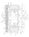
[0018]図1Aは、一実装態様に係る基板処理チャンバ100の概略断面図である。[0018] FIG. 1A is a schematic cross-sectional view of a
[0019]基板処理チャンバ100は、例えば、化学気相堆積(CVD)チャンバまたはプラズマCVDチャンバであり得る。基板処理チャンバ100は、チャンバ本体102と、チャンバリッド104とを有する。チャンバ本体102は、その中に内部領域106を含む。内部領域106は、チャンバ本体102およびチャンバリッド104によって画定されるスペースである。[0019] The
[0020]基板処理チャンバ100は、1または複数のガスの流れを処理領域110に送達するために、チャンバリッド104に結合または配置されたガス分配アセンブリ116を含む。ガス分配アセンブリ116は、チャンバリッド104に形成されたガス入口通路120に結合されたガスマニホールド118を含む。ガスマニホールド118は、1または複数のガス源122(2つを示す)からガスの流れを受け取る。1または複数のガス源122から受け取ったガスの流れは、ガスボックス124全体に分配され、バッキング板126の複数の開口部191を通って流れ、さらに、バッキング板126および面板130によって画定されるプレナム128全体に分配される。次に、ガスの流れは、面板130の複数の開口部132を通って、内部領域106の処理領域110に流れ込む。[0020] The
[0021]内部領域106は、チャンバ本体102に配置されたペデスタル138を含む。ペデスタル138は、基板処理チャンバ100内で基板136を支持する。ペデスタル138は、ペデスタル138の支持面139で基板136を支持する。ペデスタル138は、ヒータおよびその中に配置された電極を含む。電極は、直流(DC)電圧、高周波(RF)エネルギー、または交流(AC)エネルギーを内部領域106および/または処理領域110に供給し得る。[0021] The
[0022]ペデスタル138は、リフトシステム195によって内部領域106に移動可能に配置される。ペデスタル138の移動により、チャンバ本体102を通して形成されたスリット弁を介した基板136の内部領域106への移送、および内部領域106からの移送が容易になる。ペデスタル138はまた、基板136の処理のために異なる処理位置に移動され得る。[0022] The
[0023]基板処理中、ガスが複数の開口部132を通って処理領域110に流れると、ヒータがペデスタル138および支持面139を加熱する。また、基板処理中に、ペデスタル138の電極は、高周波(RF)エネルギー、交流(AC)、または直流(DC)電圧を伝播して、処理領域110でのプラズマ生成を容易にする、および/またはペデスタル138への基板136のチャッキングを容易にする。ペデスタル138の電極からの熱、ガス、およびエネルギーにより、基板処理中の基板136上への膜の堆積が容易になる。面板130(チャンバ本体102への結合を介して接地される)およびペデスタル138の電極は、容量性プラズマ結合の形成を容易にする。ペデスタル138の電極に電力が供給されると、面板130とペデスタル138との間に電界が発生し、ペデスタル138と面板130との間の処理領域110に存在するガスの原子がイオン化されて電子を放出する。イオン化された原子は、ペデスタル138まで加速して、基板136での膜形成を促進する。[0023] During substrate processing, as gas flows through the
[0024]ポンピング装置103は、基板処理チャンバ100に配置される。ポンピング装置103により、内部領域106および処理領域110からのガスの除去が容易になる。ポンピング装置103によって排気されるガスは、1または複数の処理ガスおよび/または処理残留物を含む。処理残留物は、基板136上に膜を堆積させるプロセスから生じ得る。[0024] A
[0025]ポンピング装置103は、チャンバ本体102の段付き面193に配置されたポンピングリング160を含む。段付き面193は、チャンバ本体102の底面154から上方に段が付いている。段付き面193は、ポンピングリング160を支持する。ポンピングリング160は、本体107(図1Bに示す)を含む。ポンピングリング160の本体107は、1または複数のアルミニウム、酸化アルミニウム、および/または窒化アルミニウムを含む材料から作られている。ポンピングリング160は、第1の導管176および第2の導管178を介してフォアライン172に流体連結される。フォアライン172は、第1の垂直導管131、第2の垂直導管134、水平導管135、および出口導管143を含む。一例における出口導管143は、第3の垂直導管である。一例では、第1の導管176および第2の導管178は、チャンバ本体102に形成された開口部であり、段付き表面193からチャンバ本体102の下部外面129まで延在する。本開示は、第1の導管176および第2の導管178が管であり得、底面154などのチャンバ本体102の面とポンピングリング160との間に延在する他の流れ装置であり得ることを企図する。一例として、第1の導管176および第2の導管178は、それぞれ、第1の垂直導管131および第2の垂直導管134の一部であり得る。そのような例では、第1の垂直導管131および第2の垂直導管134は、チャンバ本体102を通って延在し、ポンピングリング160に結合され得る。[0025] The
[0026]第1の導管176は、第1の端部でポンピングリング160に流体連結され、第2の端部でフォアライン172の第1の垂直導管131に流体連結される。第2の導管178は、第1の端部でポンピングリング160に流体連結され、第2の端部でフォアライン172の第2の垂直導管134に流体連結される。第1の垂直導管131および第2の垂直導管134は、水平導管135に流体連結される。水平導管135は、第1の垂直導管131に結合された第1の部分137、第2の垂直導管134に結合された第2の部分140、および出口導管143に結合された第3の部分141を含む。水平導管135は、第1の垂直導管131に隣接する第1の端部149と、第2の垂直導管134に隣接する第2の端部151とを含む。水平導管135は、単一の本体から構成され得る、または1または複数の構成要素から製造され得る。[0026] A
[0027]第1の導管176、第2の導管178、第1の垂直導管131、第2の垂直導管134、および水平導管135は、それらを通してガスを方向づけするように構成される。本開示は、第1の導管176、第2の導管178、第1の垂直導管131および第2の垂直導管134が完全に垂直である必要はなく、角度が付いていてよい、または1または複数の屈曲および/または角度を含み得ることを企図する。本開示はまた、水平導管135が完全に水平である必要はなく、角度が付いていてよい、または1または複数の屈曲および/または角度を含み得ることを企図する。[0027] The
[0028]他の実施形態と組み合わせることができる一実施形態では、ポンピングリング160は、チャンバ本体102の内側に配置され、第1の垂直導管131、第2の垂直導管134、水平導管135、および出口導管143は、チャンバ本体102の外側に配置されるまたは延在する。そのような実施形態では、第1の導管176および第2の導管178は、チャンバ本体102を通して配置される。[0028] In one embodiment, which may be combined with other embodiments, the
[0029]出口導管143は、真空ポンプ133に流体連結されて、処理領域110内の圧力を制御し、処理領域110からガスおよび残留物を排気する。真空ポンプ133は、処理領域110から、フォアライン172のポンピングリング160、第1の導管176、第2の導管178、第1の垂直導管131、第2の垂直導管134、水平導管135、および出口導管143を通してガスを排気する。[0029] The
[0030]図1Bは、一実装態様に係る、図1Aに示す基板処理チャンバ100の拡大概略部分断面図である。ポンピングリング160は、ペデスタル138の周りに配置されている。支持面139は、その上に基板136を支持するように構成される。ポンピングリング160の本体107は、上壁196、下壁194、内側半径方向壁192、および外側半径方向壁190を含む。ポンピングリング160の環帯105は、上壁196、下壁194、内側半径方向壁192、および外側半径方向壁190によって画定される。ポンピングリング160は、内側半径方向壁192および上壁196に隣接する湾曲部分157を含む。オプションの絶縁体リング159は、ポンピングリング160とペデスタル138との間に配置されている。オプションとして、ペデスタル138とリフトシステム195との間にスペース188があり得、オプションとして、リフトシステム195とチャンバ本体102との間にスペース189があり得る。オプションのスペース188および189は省略され得る。スペース188および/または189は、ペデスタル138、ポンピングリング160、チャンバ本体102、および/または他の任意の構成要素または材料によって部分的または完全に占有され得る。本開示は、ポンピングリング160が単一の本体から形成され得る、または複数の構成要素から形成され得ることを企図する。[0030] Figure IB is an enlarged schematic partial cross-sectional view of the
[0031]ポンピングリング160は、本体107の上部199に1または複数の開口部146を含む。本開示は、1または複数の開口部146が、本体107の底部など、ポンピングリング160の別の部分にあり得ることを企図している。1または複数の開口部146は、処理ガスおよび処理残留物などの流体148を、処理領域110および内部領域106から環帯105へ方向づけするように構成される。1または複数の開口部146は、処理領域110および/またはペデスタル138に対して角度が付いており、下向きおよび半径方向外向きに方向づけされたものとして図1Bに示されている。1または複数の開口部146は、本体107の上面147から湾曲部分157を通って延在する。本開示は、1または複数の開口部146が直線であり得または角度が付いていてよく、垂直または水平に配置され得ることを企図する。1または複数の開口部146は、ポンピングリング160の上面147のどこにでも配置され得る。1または複数の開口部146の位置、サイズ、形状、および/または深さは、プロセス要件および/または排気要件に基づいて変更され得る。図1Bに示す1または複数の開口部146の角度の付いた配向により、基板136上への膜の均一な堆積および流体148の均一な排気が容易になる。一例として、1または複数の開口部146の角度の付いた配向により、1または複数の開口部146の深さが延長され、背圧が調整され、流体148に追加の膨張体積が提供され得る。角度の付いた配向により、ポンピングリング160の流体148の圧力勾配および/または速度勾配の蓄積が低減または排除され得、それにより、流体148の均一な排気および基板136上への均一な堆積が促進される。流体148は、1または複数の処理ガス、処理残留物、および/またはパージガスを含む。[0031] The
[0032]ポンピングリング160は、本体107に第1の排気ポート144および第2の排気ポート145を含む。第1の排気ポート144および第2の排気ポート145は、ペデスタル138の支持面139の半径方向外側に配置されている。第1の排気ポート144および第2の排気ポート145は、環帯105に流体連結されている。第1の排気ポート144は、第1の導管176を介して第1の垂直導管131に流体連結されている。第1の排気ポート144は、流体148を環帯105から第1の導管176へ方向づけするように構成される。第2の排気ポート145は、第2の導管178を介して第2の垂直導管134に流体連結されている。第2の排気ポート145は、流体148を環帯105から第2の導管178へ方向づけするように構成される。第1の排気ポート144および第2の排気ポート145は、ポンピングリング160の反対側に配置されている。例えば、第1の排気ポート144および第2の排気ポート145は、互いに約180度離れている。[0032] The
[0033]ポンピングリング160は、第1の排気ポート144に隣接し且つ第1の排気ポート144の半径方向内側にある第1のバッフル161を含む。ポンピングリング160はまた、第2の排気ポート145に隣接し且つ第2の排気ポート145の半径方向内側にある第2のバッフル162を含む。第1のバッフル161および第2のバッフル162は、環帯105に配置されている。第1のバッフル161は、第1の排気ポート144とポンピングリング160の内側半径方向壁192との間に配置されている。第2のバッフル162は、第2の排気ポート145とポンピングリング160の内側半径方向壁192との間に配置されている。他の実施形態と組み合わせることができる一実施形態では、第1のバッフル161および第2のバッフル162は、ポンピングリング160の上壁196および下壁194に結合されている。第1のバッフル161および第2のバッフル162は、ポンピングリング160の本体107と単一の本体として形成され得る。[0033] The
[0034]図1Cは、一実装態様に係る、図1Bに示す基板処理チャンバ100の拡大概略部分断面図である。1または複数の開口部146のそれぞれは、ポンピングリング160の環帯105まで開いている第1の部分1000と、第1の部分1000と処理領域110との間にある第2の部分1001とを含む。第1の部分1000は、第2の部分1001と環帯105との間にある。第2の部分1001は、第1の部分1000よりも幅が広い。第2の部分1001は、第1の部分1000に向かってくびれている。第2の部分1001は、絶縁体リング159のテーパ面1002と、ポンピングリング160の凹面1003とによって画定される。凹面1003は、それぞれの開口部146の第1の部分1000によって画定される内面1004の半径方向外側に配置されている。肩部1005は、凹面1003と内面1004との間にある。テーパ面1002は、角度βで内面1004の線形プロファイル1006と交差し、テーパ面1002は内面1004とは同一平面上ではない。一例では、第1の部分1000は形状が円形であり、第2の部分1001は形状が円錐形である。[0034] Figure 1C is an enlarged schematic partial cross-sectional view of the
[0035]開口部146の少なくとも第1の部分1000は、水平軸1007に対してある角度で配置されている。第1の部分1000は、第1の部分1000の中心線軸1009が水平軸1007に対して角度αになるように配置されている。一例では、角度αは、-45度から45度など、-90度から90度の範囲内にある。一例では、角度αは45度である。[0035] At least a
[0036]図1Dは、一実装態様に係る、図1Aに示すポンピング装置103の拡大概略部分断面図である。第1の排気ポート144は、第1の導管176、第1の垂直導管131、および水平導管135を介して出口導管143に流体連結されている。第2の排気ポート145は、第2の導管178、第2の垂直導管134、および水平導管135を介して出口導管143に流体連結されている。[0036] FIG. 1D is an enlarged schematic partial cross-sectional view of the
[0037]第1の垂直導管131は、流体148を第1の導管176から水平導管135の第1の部分137へ方向づけするように構成される。第2の垂直導管134は、流体148を第2の導管178から水平導管135の第2の部分140へ方向づけするように構成される。水平導管135の第1の部分137および第2の部分140は、流体148をそれぞれ第1の垂直導管131および第2の垂直導管134から水平導管135の第3の部分141へ方向づけするように構成される。水平導管135の第3の部分141は、流体148を水平導管135から出口導管143へ方向づけするように構成される。出口導管143は、第1の排気ポート144および第2の排気ポート145から流体148を排気するように構成される。[0037] The first
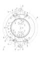
[0038]図1Eは、一実装態様に係る、線1E-1Eに沿って取られた、図1Bに示すポンピング装置およびペデスタルの概略部分断面図である。第1のバッフル161は、流体148を第1のバッフル161の第1の端部163および第2の端部164の周りへ方向づけするように構成される。流体148は、環帯105内を流れ、第1の面165を通過し、第2の面166を通過して、第1の排気ポート144に達する。一例では、第1の面165は、ポンピングリング160の内側半径方向壁192に面するように配置された凹面である。一例では、第2の面166は、第1の排気ポート144に面するように配置された凸面である。[0038] FIG. 1E is a schematic partial cross-sectional view of the pumping apparatus and pedestal shown in FIG. 1B taken along
[0039]第2のバッフル162は、流体148を第2のバッフル162の第1の端部167および第2の端部168の周りへ方向づけするように構成される。流体148は、環状部105内を流れ、第1の面169を通過し、第2の面170を通過して、第2の排気ポート145に達する。一例では、第1の面169は、ポンピングリング160の内側半径方向壁192に面するように配置された凹面である。一例では、第2の面170は、第2の排気ポート145に面するように配置された凸面である。[0039] The
[0040]他の実施形態と組み合わせることができる一実施形態では、第1のバッフル161および/または第2のバッフル162のうちの1または複数は、図1Eに示すように、湾曲したプロファイルを有する。[0040] In one embodiment, which can be combined with other embodiments, one or more of the
[0041]第1の排気ポート144および第2の排気ポート145は、それらの間に直線軸171を画定する。直線軸171は、第1のバッフル161の中心および第2のバッフル162の中心を通過するように配置されている。[0041] The
[0042]第1のバッフル161は、第1のバッフル角度A1および第2のバッフル角度A2で配置されている。第1のバッフル角度A1は、直線軸171と第1のバッフル軸173との間で測定される。第1のバッフル軸173は直線であり、第1のバッフル161の第2の端部164およびポンピングリング160の幾何学的中心174を通過する。第2のバッフル角度A2は、第1のバッフル161の直線軸171と第2のバッフル軸177との間で測定される。第2のバッフル軸177は直線であり、第1のバッフル161の第1の端部163およびポンピングリング160の幾何学的中心174を通過する。[0042] The
[0043]第2のバッフル162は、第1のバッフル角度A3および第2のバッフル角度A4で配置されている。第1のバッフル角度A3は、直線軸171と第1のバッフル軸175との間で測定される。第1のバッフル軸175は直線であり、第2のバッフル162の第2の端部168およびポンピングリング160の幾何学的中心174を通過する。第2のバッフル角度A4は、第2のバッフル162の直線軸171と第2のバッフル軸179との間で測定される。第2のバッフル軸179は直線であり、第2のバッフル162の第1の端部167およびポンピングリング160の幾何学的中心174を通過する。直線軸171は、ポンピングリング160の幾何学的中心174を通過する。[0043] The
[0044]一例では、第1のバッフル161のプロファイルおよび第2のバッフル162のプロファイルは、直線軸171に平行ではない。[0044] In one example, the profile of the
[0045]第1のバッフル161の第1のバッフル角度A1および/または第2のバッフル162の第1のバッフル角度A3のうちの1または複数は、約0.01度から約90度、例えば、約0.01度から約45度または約10度から約90度の範囲内にある。一例では、第1のバッフル161の第1のバッフル角度A1および/または第2のバッフル162の第1のバッフル角度A3のうちの1または複数は、30度、40度、45度、または55度である。一例では、第1のバッフル161の第1のバッフル角度A1および/または第2のバッフル162の第1のバッフル角度A3のうちの1または複数は、約30度から約55度の範囲内にある。一例では、第1のバッフル161の第1のバッフル角度A1および/または第2のバッフル162の第1のバッフル角度A3のうちの1または複数は、約30度である。[0045] One or more of the first baffle angles A1 of the
[0046]第1のバッフル161の第2のバッフル角度A2は、直線軸171に対する第1のバッフル角度A1の逆の値である。第2のバッフル162の第2のバッフル角度A4は、直線軸171に対する第1のバッフル角度A3の逆の値である。第1のバッフル161の第1のバッフル角度A1が45度であり、第2のバッフル162の第1のバッフル角度A3が45度である例では、第2のバッフル角度A2および第2のバッフル角度A4は、それぞれ-45度である。[0046] The second baffle angle A2 of the
[0047]一例では、直線軸171は、第1のバッフル161に最も近い開口部146および第2のバッフル162に最も近い開口部146を通過する。[0047] In one example, the
[0048]第1のバッフル161は、第2の面166と外側半径方向壁190との間に第1の間隙L3を画定する。第2のバッフル162は、第2の面170と外側半径方向壁190との間に第2の間隙L4を画定する。第1の間隙L3は、第1の排気ポート144に向かって流れる流体148の流路の一部である。第1の間隙L3は断面積を有する。第1の排気ポート144は、流体148が排気される断面積を画定する。第1の排気ポート144の断面積と第1の間隙L3の断面積との比は、0.5から2.0の範囲内である。一例では、第1の間隙L3の断面積は、第1の排気ポート144の断面積に実質的に等しい。第2の間隙L4は、第2の排気ポート145に向かって流れる流体148の流路の一部である。第2の間隙L4は断面積を有する。第2の排気ポート145は、流体148が排気される断面積を画定する。第2の排気ポート145の断面積と第2の間隙L4の断面積との比は、0.5から2.0の範囲内である。一例では、第2の間隙L4の断面積は、第2の排気ポート145の断面積に実質的に等しい。[0048] The
[0049]第1の排気ポート144および第2の排気ポート145は、ポンピングリング160の両端に配置されている。第1の排気ポート144および第2の排気ポート145は、ポンピングリング160の本体107の円周軸180の周りに互いに等距離に配置されている。第1の排気ポート144および第2の排気ポート145は、本体107の円周軸180の周りに互いに約180度のところに配置されている。第1および第2の排気ポート144、145を円周軸180に沿った特定の相対位置に配置することにより、基板処理チャンバ100からの、および基板136の周りのガスの対称的な排気が促進される。基板周囲のガスの対称的な排気を促進することで、基板に形成される欠陥および/または基板の不均一な処理の可能性が低減する。[0049] The
[0050]図1A~図1Dに、2つの導管176、178、2つの垂直導管131、134、及び2つの排気ポート144、145を備えたポンピングリング160を示したが、本開示は、より多くの導管、垂直導管、および/または排気ポートを実装し得ると考えられる。例えば、ポンピングリング160は、少なくとも3つの導管および少なくとも3つの垂直導管にそれぞれ流体連結された少なくとも3つの排気ポートを有し得る。第3の導管が第3の垂直導管に結合され得、第3の垂直導管が水平導管135に結合され得る。第1の排気ポート144、第2の排気ポート145、および第3の排気ポートは、ポンピングリング160の本体107の円周軸180に沿って互いにほぼ等距離(例えば、互いに120度)に配置され得る。1A-1D show a
[0051]ポンピングリング160、第1のバッフル161、および第2のバッフル162の構成は、処理ガスの均一な排気を促進し、環帯105内の実質的に等しい流路長で流体148の排気を促進する。例えば、ポンピングリング160は、流体148が、それぞれの第1の排気ポート144または第2の排気ポート145から異なる距離に配置された異なる開口部146を通って環帯105に入るときに、実質的に等しい流路長で流体148を排気する。第1の排気ポート144に向かって流れる流体148は、第1のバッフル161の第1の端部163または第2の端部164のうちの1つに隣接して合流する。第2の排気ポート145に向かって流れる流体148は、第2のバッフル162の第1の端部167または第2の端部168のうちの1つに隣接して合流する。合流により、流体がそれぞれの第1または第2の排気ポート144、145に到達したときに、それぞれの第1または第2の排気ポート144、145に向かって流れる流体148は、異なる開口部146を通って環帯105に入った流体148と実質的に等しい流路長を有する。一例として、流体148は、第1の位置で環帯105に入り、次に、第1の流路187に沿って流れる。流体148はまた、第2の位置で環帯105に入り、次いで、第2の流路185に沿って流れる。第1の流路187に沿って流れる流体148は、第1の面165および第2の端部164の周りの第1のバッフル161によって方向付けられる。第2の流路185に沿って流れる流体148は、第1のバッフル161の第2の端部164の周りを流れる。第1の流路187に沿って流れる流体148は、第2の流路185に沿って流れる流体148よりも第1の排気ポート144に近い位置で環帯105に入る。第1の流路187の長さは、第2の流路185の長さに実質的に等しく、流体148の均一な排気が容易になる。[0051] The configuration of the
[0052]図1Fは、一実装態様に係る、図1Dに示すポンピング装置103の下部部分概略図である。水平導管135は、半円形のU字形であるプロファイルを画定する。一例では、水平導管135は、V字形であるプロファイルを画定する。水平導管135の第1の部分137および第2の部分140は、第3の部分141から分岐している。第1の部分137は、第3の部分141に対して角度αで配置され、第2の部分140は、第3の部分141に対して角度βで配置される。第1の部分137は第1の方向186に配置され、第2の部分140は第2の方向184に配置される。第1の方向186は、第2の方向184とは異なる。水平導管135、ポンピングリング160、第1の垂直導管131、および第2の垂直導管134により、他の構成要素に干渉しないより単純な設計が容易になる。例えば、設計は、図1Aに示す基板処理チャンバ100の下に配置され得る、または下に突出し得る持ち上げ構成要素に干渉しない可能性がある。1F is a schematic diagram of a lower portion of the
[0053]第1の再帰は、第1および第2のバッフル161、162ならびに第1および第2の排気ポート144、145(図1Bに示す)を含む環帯105で発生する。第2の再帰は、第1の垂直導管131および第2の垂直導管134に結合された水平導管135で発生する。第1の再帰および第2の再帰により、実質的に等しい流体148の排気路長が促進される。第1の排気ポート144を通って排気された流体148は、水平導管135の第3の部分141において、第2の排気ポート145を通って排気された流体148と合流する。フォアライン172の出口導管143に入るにあたって、流体148は、1または複数の開口部146から出口導管143まで、実質的に等しい流路長に沿って流れてきている。流体148が異なる開口部146を通って環帯105に入り、異なる第1の排気ポート144または第2の排気ポート145を通って流れたとしても、流体148は実質的に等しい流路長に沿って流れることになる。[0053] The first return occurs at the
[0054]実質的に等しい排気路長を有することで、3つ以上の排気ポートを有する装置に近いまたは等しい均一性でのプロセスガスの排気が促進される。ポンピングリング160により、基板処理チャンバ100から等しい流量の流体が排気されやすくなる。ポンピングリング160は、2つの排気ポートを含み得、3つ以上の排気ポートの流量をシミュレートし得る。この構成は、排気された流体の流量を増進し、基板周囲のガスの対称的な排気を促進する。一例として、上記構成は、環帯105、第1の導管176、第2の導管178、第1の垂直導管131、第2の垂直導管134、および/または水平導管135における流体148の濃度勾配の形成を低減または排除する。[0054] Having substantially equal exhaust path lengths promotes exhaust of process gases with uniformity similar to or equal to that of an apparatus having three or more exhaust ports. The
[0055]本開示の利点は、基板周囲の流体の対称的な排気、基板欠陥の確率の低下、スループットの促進、工程時間の短縮、排気流体の流量の増加、実質的に等しい長さを有する流路に沿った流体排気、3つ以上の排気ポートを有する装置に近い又は等しい均一性での流体排気、排気される流体の濃度勾配の形成の低減または排除、より単純な設計、およびチャンバ構成要素との干渉を低減または最小化する設計を含む。本開示の態様は、ポンピングリング;第1のバッフル;第2のバッフル;互いに等間隔に配置された排気ポート;第1の導管;第2の導管;フォアライン;第1の垂直導管;第2の垂直導管;第1の部分、第2の部分、および第3の部分を有する水平導管;および出口導管を含む。[0055] Advantages of the present disclosure include symmetrical evacuation of fluids around the substrate, reduced probability of substrate defects, facilitated throughput, reduced process time, increased flow rate of exhaust fluids, fluid evacuation along flow paths having substantially equal lengths, fluid evacuation with uniformity approaching or equal to devices having three or more exhaust ports, reduced or eliminated formation of concentration gradients in the exhausted fluid, simpler designs, and designs that reduce or minimize interference with chamber components. Aspects of the present disclosure include a pumping ring; a first baffle; a second baffle; exhaust ports spaced equally apart from one another; a first conduit; a second conduit; a foreline; a first vertical conduit; a second vertical conduit; a horizontal conduit having a first portion, a second portion, and a third portion; and an outlet conduit.
[0056]ポンピングリングの1または複数の態様、および/または本明細書に開示されるペデスタル、導管、フォアライン、垂直導管、水平導管、および/または出口導管の1または複数の態様を組み合わせることができると考えられる。さらに、ポンピングリングの1または複数の態様、および/またはペデスタル、導管、フォアライン、垂直導管、水平導管、および/または出口導管の1または複数の態様は、前述の利点のいくつかまたはすべてを含み得る。[0056] It is contemplated that one or more aspects of the pumping ring and/or one or more aspects of the pedestal, conduit, foreline, vertical conduit, horizontal conduit, and/or exit conduit disclosed herein may be combined. Furthermore, one or more aspects of the pumping ring and/or one or more aspects of the pedestal, conduit, foreline, vertical conduit, horizontal conduit, and/or exit conduit may include some or all of the advantages described above.
[0057]前述の内容は本開示の実施形態を対象としているが、その基本的な範囲から逸脱することなく、本開示の他のさらなる実施形態を考案することが可能である。本開示はまた、本明細書に記載の実施形態の1又は複数の態様を、記載の他の態様の1又は複数の代わりに使用することができると考えられる。本開示の範囲は、以下の特許請求の範囲によって決定される。[0057] While the foregoing is directed to embodiments of the present disclosure, other and further embodiments of the present disclosure may be devised without departing from the basic scope thereof. The present disclosure also contemplates that one or more aspects of the embodiments described herein may be substituted for one or more of the other aspects described. The scope of the present disclosure is determined by the following claims.
Claims (15)
Translated fromJapanese上壁、下壁、内側半径方向壁、及び外側半径方向壁を含む本体と、
前記上壁、前記下壁、前記内側半径方向壁、及び前記外側半径方向壁によって画定される環帯と、
前記環帯に流体連結された前記本体の第1の排気ポートと、
前記環帯に流体連結された前記本体の第2の排気ポートと、
前記第1の排気ポートに隣接して前記環帯内に配置された第1のバッフルと、
前記第2の排気ポートに隣接して前記環帯内に配置された第2のバッフルと
を備え、
前記第1の排気ポート及び前記第2の排気ポートは、それらの間に直線軸を画定し、
前記第1のバッフル及び前記第2のバッフルは、それぞれの第1のバッフル又は第2のバッフルの端部と前記直線軸との間で測定されるバッフル角度で配置され、前記バッフル角度が0.01度から55度の範囲内である、ポンピングリング。 1. A pumping ring for a substrate processing chamber, comprising:
a body including an upper wall, a lower wall, an inner radial wall, and an outer radial wall;
an annulus defined by the upper wall, the lower wall, the inner radial wall, and the outer radial wall;
a first exhaust port in the body fluidly connected to the annulus;
a second exhaust port in the body fluidly connected to the annulus;
a first baffle disposed within the annulus adjacent the first exhaust port;
a second baffle disposed within the annulus adjacent the second exhaust port;
the first exhaust port and the second exhaust port define a linear axis therebetween;
the first baffle and the second baffle are arranged at a baffle angle measured between an end of the respective first baffle or second baffle and the linear axis, the baffle angle being in the range of 0.01 degrees to 55 degrees.
上壁、下壁、内側半径方向壁、及び外側半径方向壁を含む本体と、
前記上壁、前記下壁、前記内側半径方向壁、及び前記外側半径方向壁によって画定される環帯と、
前記環帯に流体連結された前記本体の第1の排気ポートと、
前記環帯に流体連結された前記本体の第2の排気ポートと、
前記第1の排気ポートに隣接して前記環帯内に配置された第1のバッフルと、
前記第2の排気ポートに隣接して前記環帯内に配置された第2のバッフルと
を備え、
前記第1のバッフル及び前記第2のバッフルは、流体を、それぞれの第1のバッフル及び第2のバッフルの第1の端部及び第2の端部の周りへ方向づけするように構成され、前記流体は、処理ガス及び処理残留物を含む、ポンピングリング。1. A pumping ring for a substrate processing chamber, comprising:
a body including an upper wall, a lower wall, an inner radial wall, and an outer radial wall;
an annulus defined by the upper wall, the lower wall, the inner radial wall, and the outer radial wall;
a first exhaust port in the body fluidly connected to the annulus;
a second exhaust port in the body fluidly connected to the annulus;
a first baffle disposed within the annulus adjacent the first exhaust port;
a second baffle disposed within the annulus adjacent the second exhaust port; and
Equipped with
A pumping ring, wherein the first baffle and the second baffle are configured to direct afluid around first and second ends of the respective first and second baffles, the fluid including a process gas and a process residue.
上面、上壁、下壁、内側半径方向壁、及び外側半径方向壁を含む本体と、
それを通して流体を方向づけするように構成された前記本体の1又は複数の開口部と、
前記本体の第1の排気ポートと、
前記本体の第2の排気ポートと、
前記第1の排気ポートに隣接して配置された第1のバッフルと、
前記第2の排気ポートに隣接して配置された第2のバッフルと
を備え、
前記第1の排気ポート及び前記第2の排気ポートは、それらの間に直線軸を画定し、
前記第1のバッフル及び前記第2のバッフルは、それぞれの第1のバッフル又は第2のバッフルの端部と前記直線軸との間で測定されるバッフル角度で配置され、前記バッフル角度が0.01度から55度の範囲内である、ポンピングリング。 1. A pumping ring for a substrate processing chamber, comprising:
a body including an upper surface, an upper wall, a lower wall, an inner radial wall, and an outer radial wall;
one or more openings in the body configured to direct a fluid therethrough;
a first exhaust port in the body;
a second exhaust port in the body; and
a first baffle disposed adjacent to the first exhaust port;
a second baffle disposed adjacent to the second exhaust port; and
Equippedwith
the first exhaust port and the second exhaust port define a linear axis therebetween;
the first baffle and the second baffle are arranged at a baffle angle measured between an end of the respective first baffle or second baffle and the linear axis, the baffle angle being in the range of 0.01 degrees to 55 degrees.
チャンバ本体と、
前記チャンバ本体内に配置されたペデスタルと、
前記ペデスタルの周りに配置され、上壁、下壁、内側半径方向壁、及び外側半径方向壁を含むポンピングリングと、
前記上壁、前記下壁、前記内側半径方向壁、及び前記外側半径方向壁によって画定される環帯と、
前記環帯に流体連結された前記ポンピングリングの第1の排気ポートと、
前記環帯に流体連結された前記ポンピングリングの第2の排気ポートと、
前記第1の排気ポートに隣接して前記環帯内に配置された第1のバッフルと、
前記第2の排気ポートに隣接して前記環帯内に配置された第2のバッフルと、
前記第1の排気ポート及び前記第2の排気ポートに流体連結されたフォアラインと
を備え、
前記第1の排気ポート及び前記第2の排気ポートは、それらの間に直線軸を画定し、
前記第1のバッフル及び前記第2のバッフルは、それぞれの第1のバッフル又は第2のバッフルの端部と前記直線軸との間で測定されるバッフル角度で配置され、前記バッフル角度が0.01度から55度の範囲内である、基板処理チャンバ。 1. A substrate processing chamber comprising:
A chamber body;
a pedestal disposed within the chamber body;
a pumping ring disposed about the pedestal and including an upper wall, a lower wall, an inner radial wall, and an outer radial wall;
an annulus defined by the upper wall, the lower wall, the inner radial wall, and the outer radial wall;
a first exhaust port of the pumping ring fluidly connected to the annulus;
a second exhaust port of the pumping ring fluidly connected to the annulus;
a first baffle disposed within the annulus adjacent the first exhaust port;
a second baffle disposed within the annulus adjacent the second exhaust port;
a foreline fluidly connected to the first exhaust port and the second exhaust port;
the first exhaust port and the second exhaust port define a linear axis therebetween;
1. A substrate processing chamber, wherein the first baffle and the second baffle are disposed at a baffle angle measured between an end of the respective first baffle or second baffle and the linear axis, the baffle angle being in the range of 0.01 degrees to 55 degrees.
前記水平導管が、前記第1の垂直導管に結合された第1の部分、前記第2の垂直導管に結合された第2の部分、及び前記フォアラインに結合された第3の部分を含み、前記第1の部分及び前記第2の部分は前記第3の部分から分岐し、
前記水平導管が、前記第1の垂直導管に隣接する第1の端部と、前記第2の垂直導管に隣接する第2の端部とを含む、請求項11に記載の基板処理チャンバ。 the first exhaust port is fluidly connected to the foreline via a first vertical conduit and a horizontal conduit, and the second exhaust port is fluidly connected to the foreline via a second vertical conduit and the horizontal conduit;
the horizontal conduit includes a first portion coupled to the first vertical conduit, a second portion coupled to the second vertical conduit, and a third portion coupled to the foreline, the first portion and the second portion branching off from the third portion;
The substrate processing chamber of claim 11 , wherein the horizontal conduit includes a first end adjacent to the first vertical conduit and a second end adjacent to the second vertical conduit.
Applications Claiming Priority (5)
| Application Number | Priority Date | Filing Date | Title |
|---|---|---|---|
| US201962789905P | 2019-01-08 | 2019-01-08 | |
| US62/789,905 | 2019-01-08 | ||
| US201962826407P | 2019-03-29 | 2019-03-29 | |
| US62/826,407 | 2019-03-29 | ||
| PCT/US2019/061656WO2020146047A1 (en) | 2019-01-08 | 2019-11-15 | Pumping apparatus and method for substrate processing chambers |
Publications (2)
| Publication Number | Publication Date |
|---|---|
| JP2022518134A JP2022518134A (en) | 2022-03-14 |
| JP7477515B2true JP7477515B2 (en) | 2024-05-01 |
Family
ID=71404958
Family Applications (1)
| Application Number | Title | Priority Date | Filing Date |
|---|---|---|---|
| JP2021538731AActiveJP7477515B2 (en) | 2019-01-08 | 2019-11-15 | Pumping apparatus and method for a substrate processing chamber - Patents.com |
Country Status (6)
| Country | Link |
|---|---|
| US (1) | US11078568B2 (en) |
| JP (1) | JP7477515B2 (en) |
| KR (1) | KR102752575B1 (en) |
| CN (1) | CN113169101B (en) |
| TW (1) | TWI841656B (en) |
| WO (1) | WO2020146047A1 (en) |
Families Citing this family (12)
| Publication number | Priority date | Publication date | Assignee | Title |
|---|---|---|---|---|
| KR102477302B1 (en) | 2015-10-05 | 2022-12-13 | 주성엔지니어링(주) | Substrate treatment apparatus having exhaust gas cracker and exhaust gas treatment method of the same |
| US11952660B2 (en)* | 2019-07-29 | 2024-04-09 | Applied Materials, Inc. | Semiconductor processing chambers and methods for cleaning the same |
| KR102733104B1 (en)* | 2019-09-05 | 2024-11-22 | 에이에스엠 아이피 홀딩 비.브이. | Substrate processing apparatus |
| US12068144B2 (en)* | 2020-07-19 | 2024-08-20 | Applied Materials, Inc. | Multi-stage pumping liner |
| KR102817898B1 (en)* | 2021-01-25 | 2025-06-10 | 주식회사 케이씨텍 | Exhaust device |
| US12012653B2 (en) | 2021-03-23 | 2024-06-18 | Applied Materials, Inc. | Cleaning assemblies for substrate processing chambers |
| CN114975054B (en) | 2021-07-16 | 2025-08-01 | 北京屹唐半导体科技股份有限公司 | Pressure control system for multi-head processing chamber of plasma processing apparatus |
| US20230265560A1 (en)* | 2022-02-23 | 2023-08-24 | Applied Materials, Inc. | Pumping liner and methods of manufacture and use thereof |
| TW202400822A (en)* | 2022-05-13 | 2024-01-01 | 荷蘭商Asm Ip私人控股有限公司 | Film forming apparatus |
| WO2024076480A1 (en)* | 2022-10-06 | 2024-04-11 | Lam Research Corporation | Annular pumping for chamber |
| US20250037976A1 (en)* | 2023-07-28 | 2025-01-30 | Applied Materials, Inc. | Process stack for cvd plasma treatment |
| US20250279265A1 (en)* | 2024-02-29 | 2025-09-04 | Applied Materials, Inc. | Small cell reactors with shared foreline and pressure conduit |
Citations (4)
| Publication number | Priority date | Publication date | Assignee | Title |
|---|---|---|---|---|
| JP2000058298A (en) | 1998-08-06 | 2000-02-25 | Foi:Kk | Plasma reactor |
| US20120009765A1 (en) | 2010-07-12 | 2012-01-12 | Applied Materials, Inc. | Compartmentalized chamber |
| JP2012015451A (en) | 2010-07-05 | 2012-01-19 | Tokyo Electron Ltd | Substrate processing device and substrate processing method |
| US20150187545A1 (en) | 2013-12-26 | 2015-07-02 | Psk Inc. | Substrate treating apparatus and method |
Family Cites Families (78)
| Publication number | Priority date | Publication date | Assignee | Title |
|---|---|---|---|---|
| JP2763222B2 (en)* | 1991-12-13 | 1998-06-11 | 三菱電機株式会社 | Chemical vapor deposition method, chemical vapor deposition processing system and chemical vapor deposition apparatus therefor |
| JPH05326410A (en)* | 1992-05-25 | 1993-12-10 | Tokyo Electron Yamanashi Kk | Plasma treatment apparatus |
| US6500734B2 (en) | 1993-07-30 | 2002-12-31 | Applied Materials, Inc. | Gas inlets for wafer processing chamber |
| US5441568A (en)* | 1994-07-15 | 1995-08-15 | Applied Materials, Inc. | Exhaust baffle for uniform gas flow pattern |
| JP3192370B2 (en)* | 1995-06-08 | 2001-07-23 | 東京エレクトロン株式会社 | Plasma processing equipment |
| US5895530A (en)* | 1996-02-26 | 1999-04-20 | Applied Materials, Inc. | Method and apparatus for directing fluid through a semiconductor processing chamber |
| US5846332A (en) | 1996-07-12 | 1998-12-08 | Applied Materials, Inc. | Thermally floating pedestal collar in a chemical vapor deposition chamber |
| JPH1136076A (en) | 1997-07-16 | 1999-02-09 | Tokyo Electron Ltd | Cvd deposition apparatus and cvd deposition method |
| US6261426B1 (en) | 1999-01-22 | 2001-07-17 | International Business Machines Corporation | Method and apparatus for enhancing the uniformity of electrodeposition or electroetching |
| US6261408B1 (en)* | 2000-02-16 | 2001-07-17 | Applied Materials, Inc. | Method and apparatus for semiconductor processing chamber pressure control |
| US6531069B1 (en)* | 2000-06-22 | 2003-03-11 | International Business Machines Corporation | Reactive Ion Etching chamber design for flip chip interconnections |
| EP1308992A4 (en)* | 2000-08-11 | 2006-01-18 | Tokyo Electron Ltd | Device and method for processing substrate |
| DE10064942A1 (en)* | 2000-12-23 | 2002-07-04 | Aixtron Ag | Process for the deposition of crystalline layers in particular |
| US6878206B2 (en)* | 2001-07-16 | 2005-04-12 | Applied Materials, Inc. | Lid assembly for a processing system to facilitate sequential deposition techniques |
| US7390366B2 (en)* | 2001-11-05 | 2008-06-24 | Jusung Engineering Co., Ltd. | Apparatus for chemical vapor deposition |
| US6777352B2 (en)* | 2002-02-11 | 2004-08-17 | Applied Materials, Inc. | Variable flow deposition apparatus and method in semiconductor substrate processing |
| US6921556B2 (en)* | 2002-04-12 | 2005-07-26 | Asm Japan K.K. | Method of film deposition using single-wafer-processing type CVD |
| US7468104B2 (en)* | 2002-05-17 | 2008-12-23 | Micron Technology, Inc. | Chemical vapor deposition apparatus and deposition method |
| US6890596B2 (en)* | 2002-08-15 | 2005-05-10 | Micron Technology, Inc. | Deposition methods |
| JP4113755B2 (en)* | 2002-10-03 | 2008-07-09 | 東京エレクトロン株式会社 | Processing equipment |
| US6905737B2 (en)* | 2002-10-11 | 2005-06-14 | Applied Materials, Inc. | Method of delivering activated species for rapid cyclical deposition |
| EP1420080A3 (en)* | 2002-11-14 | 2005-11-09 | Applied Materials, Inc. | Apparatus and method for hybrid chemical deposition processes |
| US7408225B2 (en)* | 2003-10-09 | 2008-08-05 | Asm Japan K.K. | Apparatus and method for forming thin film using upstream and downstream exhaust mechanisms |
| JP2007511902A (en)* | 2003-10-29 | 2007-05-10 | エーエスエム アメリカ インコーポレイテッド | Reactor for thin film growth |
| JP4379585B2 (en) | 2003-12-17 | 2009-12-09 | 信越半導体株式会社 | Vapor phase growth apparatus and epitaxial wafer manufacturing method |
| US7273526B2 (en)* | 2004-04-15 | 2007-09-25 | Asm Japan K.K. | Thin-film deposition apparatus |
| JP4879509B2 (en)* | 2004-05-21 | 2012-02-22 | 株式会社アルバック | Vacuum deposition system |
| WO2005117083A1 (en)* | 2004-05-27 | 2005-12-08 | Tokyo Electron Limited | Substrate processing apparatus |
| FR2882064B1 (en)* | 2005-02-17 | 2007-05-11 | Snecma Propulsion Solide Sa | PROCESS FOR THE DENSIFICATION OF THIN POROUS SUBSTRATES BY CHEMICAL VAPOR PHASE INFILTRATION AND DEVICE FOR LOADING SUCH SUBSTRATES |
| US8282768B1 (en)* | 2005-04-26 | 2012-10-09 | Novellus Systems, Inc. | Purging of porogen from UV cure chamber |
| CN101370963B (en)* | 2006-01-19 | 2012-03-28 | Asm美国公司 | High temperature atomic layer deposition intake manifold |
| TW200809926A (en) | 2006-05-31 | 2008-02-16 | Sumco Techxiv Corp | Apparatus and method for depositing layer on substrate |
| US7435484B2 (en)* | 2006-09-01 | 2008-10-14 | Asm Japan K.K. | Ruthenium thin film-formed structure |
| US8048226B2 (en)* | 2007-03-30 | 2011-11-01 | Tokyo Electron Limited | Method and system for improving deposition uniformity in a vapor deposition system |
| JP5347294B2 (en)* | 2007-09-12 | 2013-11-20 | 東京エレクトロン株式会社 | Film forming apparatus, film forming method, and storage medium |
| US20090084317A1 (en) | 2007-09-28 | 2009-04-02 | Applied Materials, Inc. | Atomic layer deposition chamber and components |
| US8298338B2 (en)* | 2007-12-26 | 2012-10-30 | Samsung Electronics Co., Ltd. | Chemical vapor deposition apparatus |
| JP2009188332A (en)* | 2008-02-08 | 2009-08-20 | Tokyo Electron Ltd | Substrate-mounting stand for plasma processing apparatus, plasma processing apparatus and method of forming insulating film |
| KR101004822B1 (en)* | 2008-04-18 | 2010-12-28 | 삼성엘이디 주식회사 | Chemical vapor deposition apparatus |
| JP2010047818A (en)* | 2008-08-25 | 2010-03-04 | Toshiba Corp | Semiconductor manufacturing equipment and semiconductor manufacturing method |
| JP5453768B2 (en)* | 2008-11-05 | 2014-03-26 | 豊田合成株式会社 | Compound semiconductor manufacturing apparatus, compound semiconductor manufacturing method, and compound semiconductor manufacturing jig |
| US8512472B2 (en)* | 2008-11-13 | 2013-08-20 | Applied Materials, Inc. | Method and apparatus to enhance process gas temperature in a CVD reactor |
| JP2010263112A (en) | 2009-05-08 | 2010-11-18 | Sumco Corp | Epitaxial growth device and method for manufacturing silicon epitaxial wafer |
| JP5359698B2 (en)* | 2009-08-31 | 2013-12-04 | 豊田合成株式会社 | Compound semiconductor manufacturing apparatus, compound semiconductor manufacturing method, and compound semiconductor |
| WO2011044451A2 (en)* | 2009-10-09 | 2011-04-14 | Applied Materials, Inc. | Multi-gas centrally cooled showerhead design |
| WO2011100293A2 (en) | 2010-02-12 | 2011-08-18 | Applied Materials, Inc. | Process chamber gas flow improvements |
| JP5567392B2 (en)* | 2010-05-25 | 2014-08-06 | 東京エレクトロン株式会社 | Plasma processing equipment |
| US9728429B2 (en)* | 2010-07-27 | 2017-08-08 | Lam Research Corporation | Parasitic plasma prevention in plasma processing chambers |
| JP5644256B2 (en)* | 2010-08-20 | 2014-12-24 | 豊田合成株式会社 | Compound semiconductor manufacturing apparatus and compound semiconductor manufacturing method |
| KR101847026B1 (en)* | 2011-03-01 | 2018-04-09 | 어플라이드 머티어리얼스, 인코포레이티드 | Vacuum chambers with shared pump |
| JP6056403B2 (en)* | 2012-11-15 | 2017-01-11 | 東京エレクトロン株式会社 | Deposition equipment |
| KR101375742B1 (en)* | 2012-12-18 | 2014-03-19 | 주식회사 유진테크 | Apparatus for processing substrate |
| US20140235069A1 (en)* | 2013-02-15 | 2014-08-21 | Novellus Systems, Inc. | Multi-plenum showerhead with temperature control |
| FR3002241B1 (en)* | 2013-02-21 | 2015-11-20 | Altatech Semiconductor | CHEMICAL VAPOR DEPOSITION DEVICE |
| FR3002242B1 (en) | 2013-02-21 | 2015-04-03 | Altatech Semiconductor | CHEMICAL VAPOR DEPOSITION DEVICE |
| WO2014178160A1 (en)* | 2013-04-30 | 2014-11-06 | 東京エレクトロン株式会社 | Film formation device |
| US9028765B2 (en)* | 2013-08-23 | 2015-05-12 | Lam Research Corporation | Exhaust flow spreading baffle-riser to optimize remote plasma window clean |
| US9837250B2 (en)* | 2013-08-30 | 2017-12-05 | Applied Materials, Inc. | Hot wall reactor with cooled vacuum containment |
| KR101560623B1 (en)* | 2014-01-03 | 2015-10-15 | 주식회사 유진테크 | Substrate processing apparatus and substrate processing method |
| KR101535155B1 (en)* | 2014-01-09 | 2015-07-09 | 주식회사 유진테크 | Apparatus for processing substrate |
| US9673092B2 (en)* | 2014-03-06 | 2017-06-06 | Asm Ip Holding B.V. | Film forming apparatus, and method of manufacturing semiconductor device |
| JP5941491B2 (en)* | 2014-03-26 | 2016-06-29 | 株式会社日立国際電気 | Substrate processing apparatus, semiconductor device manufacturing method, and program |
| JP5800969B1 (en)* | 2014-08-27 | 2015-10-28 | 株式会社日立国際電気 | Substrate processing apparatus, semiconductor device manufacturing method, program, and recording medium |
| US9885112B2 (en)* | 2014-12-02 | 2018-02-06 | Asm Ip Holdings B.V. | Film forming apparatus |
| JP6503730B2 (en)* | 2014-12-22 | 2019-04-24 | 東京エレクトロン株式会社 | Film deposition system |
| KR20160083715A (en)* | 2015-01-02 | 2016-07-12 | 삼성전자주식회사 | Semiconductor processing apparatus having a gas spray unit |
| US9963782B2 (en)* | 2015-02-12 | 2018-05-08 | Asm Ip Holding B.V. | Semiconductor manufacturing apparatus |
| US20170051402A1 (en)* | 2015-08-17 | 2017-02-23 | Asm Ip Holding B.V. | Susceptor and substrate processing apparatus |
| US10157755B2 (en) | 2015-10-01 | 2018-12-18 | Lam Research Corporation | Purge and pumping structures arranged beneath substrate plane to reduce defects |
| KR102477302B1 (en)* | 2015-10-05 | 2022-12-13 | 주성엔지니어링(주) | Substrate treatment apparatus having exhaust gas cracker and exhaust gas treatment method of the same |
| US9909214B2 (en)* | 2015-10-15 | 2018-03-06 | Asm Ip Holding B.V. | Method for depositing dielectric film in trenches by PEALD |
| TWI727024B (en)* | 2016-04-15 | 2021-05-11 | 美商應用材料股份有限公司 | Micro-volume deposition chamber |
| CN110050333B (en)* | 2016-12-08 | 2023-06-09 | 应用材料公司 | Temporal atomic layer deposition processing chamber |
| US10604841B2 (en)* | 2016-12-14 | 2020-03-31 | Lam Research Corporation | Integrated showerhead with thermal control for delivering radical and precursor gas to a downstream chamber to enable remote plasma film deposition |
| US10600624B2 (en) | 2017-03-10 | 2020-03-24 | Applied Materials, Inc. | System and method for substrate processing chambers |
| KR102096700B1 (en)* | 2017-03-29 | 2020-04-02 | 도쿄엘렉트론가부시키가이샤 | Substrate processing apparatus and substrate procesing method |
| JP7055035B2 (en)* | 2018-03-02 | 2022-04-15 | 東京エレクトロン株式会社 | Vacuum processing equipment and exhaust control method |
| JP2020033619A (en)* | 2018-08-30 | 2020-03-05 | キオクシア株式会社 | Exhaust piping device and cleaning device |
- 2019
- 2019-11-15JPJP2021538731Apatent/JP7477515B2/enactiveActive
- 2019-11-15KRKR1020217021337Apatent/KR102752575B1/enactiveActive
- 2019-11-15WOPCT/US2019/061656patent/WO2020146047A1/ennot_activeCeased
- 2019-11-15USUS16/685,340patent/US11078568B2/enactiveActive
- 2019-11-15CNCN201980082733.5Apatent/CN113169101B/enactiveActive
- 2019-12-30TWTW108148331Apatent/TWI841656B/enactive
Patent Citations (4)
| Publication number | Priority date | Publication date | Assignee | Title |
|---|---|---|---|---|
| JP2000058298A (en) | 1998-08-06 | 2000-02-25 | Foi:Kk | Plasma reactor |
| JP2012015451A (en) | 2010-07-05 | 2012-01-19 | Tokyo Electron Ltd | Substrate processing device and substrate processing method |
| US20120009765A1 (en) | 2010-07-12 | 2012-01-12 | Applied Materials, Inc. | Compartmentalized chamber |
| US20150187545A1 (en) | 2013-12-26 | 2015-07-02 | Psk Inc. | Substrate treating apparatus and method |
Also Published As
| Publication number | Publication date |
|---|---|
| TWI841656B (en) | 2024-05-11 |
| WO2020146047A1 (en) | 2020-07-16 |
| TW202035874A (en) | 2020-10-01 |
| CN113169101A (en) | 2021-07-23 |
| CN113169101B (en) | 2022-09-30 |
| JP2022518134A (en) | 2022-03-14 |
| KR20210102337A (en) | 2021-08-19 |
| KR102752575B1 (en) | 2025-01-09 |
| US11078568B2 (en) | 2021-08-03 |
| US20200216952A1 (en) | 2020-07-09 |
Similar Documents
| Publication | Publication Date | Title |
|---|---|---|
| JP7477515B2 (en) | Pumping apparatus and method for a substrate processing chamber - Patents.com | |
| TWI671792B (en) | Substrate processing apparatus | |
| CN109155250B (en) | Systems and methods for improved semiconductor etching and component protection | |
| CN109155251B (en) | Systems and methods for improved semiconductor etching and component protection | |
| TWI722871B (en) | Lid and lid assembly kit for substrate processing chamber | |
| JP6240607B2 (en) | Gas delivery and distribution for homogeneous processes in a linear large area plasma reactor. | |
| CN103094045B (en) | Symmetric plasma processing chamber | |
| TWI871332B (en) | Isolator apparatus and methods for substrate processing chambers | |
| TWI872320B (en) | Hardware to prevent bottom purge incursion in application volume and process gas diffusion below heater | |
| TWI844439B (en) | Uniform in situ cleaning and deposition | |
| KR20230024385A (en) | Asymmetric Exhaust Pumping Plate Design for Semiconductor Processing Chambers | |
| US20180258531A1 (en) | Diffuser design for flowable cvd | |
| TWI892593B (en) | Semiconductor processing chamber, purge ring, and method of processing a substrate | |
| US20240352580A1 (en) | Side pumping chamber and downstream residue management hardware | |
| TW202432881A (en) | Furnaces for plasma enhanced thin film deposition | |
| CN117344284A (en) | Semiconductor processing apparatus for processing multiple substrates with cross flow |
Legal Events
| Date | Code | Title | Description |
|---|---|---|---|
| A621 | Written request for application examination | Free format text:JAPANESE INTERMEDIATE CODE: A621 Effective date:20221108 | |
| A977 | Report on retrieval | Free format text:JAPANESE INTERMEDIATE CODE: A971007 Effective date:20231122 | |
| A131 | Notification of reasons for refusal | Free format text:JAPANESE INTERMEDIATE CODE: A131 Effective date:20231128 | |
| A521 | Request for written amendment filed | Free format text:JAPANESE INTERMEDIATE CODE: A523 Effective date:20240228 | |
| TRDD | Decision of grant or rejection written | ||
| A01 | Written decision to grant a patent or to grant a registration (utility model) | Free format text:JAPANESE INTERMEDIATE CODE: A01 Effective date:20240319 | |
| A61 | First payment of annual fees (during grant procedure) | Free format text:JAPANESE INTERMEDIATE CODE: A61 Effective date:20240418 | |
| R150 | Certificate of patent or registration of utility model | Ref document number:7477515 Country of ref document:JP Free format text:JAPANESE INTERMEDIATE CODE: R150 |