JP7472940B2 - Battery monitoring device, battery ECU, and satellite - Google Patents
Battery monitoring device, battery ECU, and satelliteDownload PDFInfo
- Publication number
- JP7472940B2 JP7472940B2JP2022126955AJP2022126955AJP7472940B2JP 7472940 B2JP7472940 B2JP 7472940B2JP 2022126955 AJP2022126955 AJP 2022126955AJP 2022126955 AJP2022126955 AJP 2022126955AJP 7472940 B2JP7472940 B2JP 7472940B2
- Authority
- JP
- Japan
- Prior art keywords
- parent
- battery
- unit
- child
- monitoring device
- Prior art date
- Legal status (The legal status is an assumption and is not a legal conclusion. Google has not performed a legal analysis and makes no representation as to the accuracy of the status listed.)
- Active
Links
Images


Classifications
- G—PHYSICS
- G01—MEASURING; TESTING
- G01R—MEASURING ELECTRIC VARIABLES; MEASURING MAGNETIC VARIABLES
- G01R31/00—Arrangements for testing electric properties; Arrangements for locating electric faults; Arrangements for electrical testing characterised by what is being tested not provided for elsewhere
- G01R31/36—Arrangements for testing, measuring or monitoring the electrical condition of accumulators or electric batteries, e.g. capacity or state of charge [SoC]
- G01R31/371—Arrangements for testing, measuring or monitoring the electrical condition of accumulators or electric batteries, e.g. capacity or state of charge [SoC] with remote indication, e.g. on external chargers
- B—PERFORMING OPERATIONS; TRANSPORTING
- B60—VEHICLES IN GENERAL
- B60L—PROPULSION OF ELECTRICALLY-PROPELLED VEHICLES; SUPPLYING ELECTRIC POWER FOR AUXILIARY EQUIPMENT OF ELECTRICALLY-PROPELLED VEHICLES; ELECTRODYNAMIC BRAKE SYSTEMS FOR VEHICLES IN GENERAL; MAGNETIC SUSPENSION OR LEVITATION FOR VEHICLES; MONITORING OPERATING VARIABLES OF ELECTRICALLY-PROPELLED VEHICLES; ELECTRIC SAFETY DEVICES FOR ELECTRICALLY-PROPELLED VEHICLES
- B60L58/00—Methods or circuit arrangements for monitoring or controlling batteries or fuel cells, specially adapted for electric vehicles
- B60L58/10—Methods or circuit arrangements for monitoring or controlling batteries or fuel cells, specially adapted for electric vehicles for monitoring or controlling batteries
- B60L58/18—Methods or circuit arrangements for monitoring or controlling batteries or fuel cells, specially adapted for electric vehicles for monitoring or controlling batteries of two or more battery modules
- B—PERFORMING OPERATIONS; TRANSPORTING
- B60—VEHICLES IN GENERAL
- B60L—PROPULSION OF ELECTRICALLY-PROPELLED VEHICLES; SUPPLYING ELECTRIC POWER FOR AUXILIARY EQUIPMENT OF ELECTRICALLY-PROPELLED VEHICLES; ELECTRODYNAMIC BRAKE SYSTEMS FOR VEHICLES IN GENERAL; MAGNETIC SUSPENSION OR LEVITATION FOR VEHICLES; MONITORING OPERATING VARIABLES OF ELECTRICALLY-PROPELLED VEHICLES; ELECTRIC SAFETY DEVICES FOR ELECTRICALLY-PROPELLED VEHICLES
- B60L58/00—Methods or circuit arrangements for monitoring or controlling batteries or fuel cells, specially adapted for electric vehicles
- B60L58/10—Methods or circuit arrangements for monitoring or controlling batteries or fuel cells, specially adapted for electric vehicles for monitoring or controlling batteries
- B60L58/12—Methods or circuit arrangements for monitoring or controlling batteries or fuel cells, specially adapted for electric vehicles for monitoring or controlling batteries responding to state of charge [SoC]
- G—PHYSICS
- G01—MEASURING; TESTING
- G01R—MEASURING ELECTRIC VARIABLES; MEASURING MAGNETIC VARIABLES
- G01R31/00—Arrangements for testing electric properties; Arrangements for locating electric faults; Arrangements for electrical testing characterised by what is being tested not provided for elsewhere
- G01R31/36—Arrangements for testing, measuring or monitoring the electrical condition of accumulators or electric batteries, e.g. capacity or state of charge [SoC]
- G01R31/382—Arrangements for monitoring battery or accumulator variables, e.g. SoC
- G01R31/3835—Arrangements for monitoring battery or accumulator variables, e.g. SoC involving only voltage measurements
- G—PHYSICS
- G01—MEASURING; TESTING
- G01R—MEASURING ELECTRIC VARIABLES; MEASURING MAGNETIC VARIABLES
- G01R31/00—Arrangements for testing electric properties; Arrangements for locating electric faults; Arrangements for electrical testing characterised by what is being tested not provided for elsewhere
- G01R31/36—Arrangements for testing, measuring or monitoring the electrical condition of accumulators or electric batteries, e.g. capacity or state of charge [SoC]
- G01R31/396—Acquisition or processing of data for testing or for monitoring individual cells or groups of cells within a battery
- H—ELECTRICITY
- H04—ELECTRIC COMMUNICATION TECHNIQUE
- H04W—WIRELESS COMMUNICATION NETWORKS
- H04W76/00—Connection management
- H04W76/10—Connection setup
- B—PERFORMING OPERATIONS; TRANSPORTING
- B60—VEHICLES IN GENERAL
- B60L—PROPULSION OF ELECTRICALLY-PROPELLED VEHICLES; SUPPLYING ELECTRIC POWER FOR AUXILIARY EQUIPMENT OF ELECTRICALLY-PROPELLED VEHICLES; ELECTRODYNAMIC BRAKE SYSTEMS FOR VEHICLES IN GENERAL; MAGNETIC SUSPENSION OR LEVITATION FOR VEHICLES; MONITORING OPERATING VARIABLES OF ELECTRICALLY-PROPELLED VEHICLES; ELECTRIC SAFETY DEVICES FOR ELECTRICALLY-PROPELLED VEHICLES
- B60L2240/00—Control parameters of input or output; Target parameters
- B60L2240/40—Drive Train control parameters
- B60L2240/54—Drive Train control parameters related to batteries
- B60L2240/547—Voltage
- B—PERFORMING OPERATIONS; TRANSPORTING
- B60—VEHICLES IN GENERAL
- B60L—PROPULSION OF ELECTRICALLY-PROPELLED VEHICLES; SUPPLYING ELECTRIC POWER FOR AUXILIARY EQUIPMENT OF ELECTRICALLY-PROPELLED VEHICLES; ELECTRODYNAMIC BRAKE SYSTEMS FOR VEHICLES IN GENERAL; MAGNETIC SUSPENSION OR LEVITATION FOR VEHICLES; MONITORING OPERATING VARIABLES OF ELECTRICALLY-PROPELLED VEHICLES; ELECTRIC SAFETY DEVICES FOR ELECTRICALLY-PROPELLED VEHICLES
- B60L2240/00—Control parameters of input or output; Target parameters
- B60L2240/80—Time limits
- Y—GENERAL TAGGING OF NEW TECHNOLOGICAL DEVELOPMENTS; GENERAL TAGGING OF CROSS-SECTIONAL TECHNOLOGIES SPANNING OVER SEVERAL SECTIONS OF THE IPC; TECHNICAL SUBJECTS COVERED BY FORMER USPC CROSS-REFERENCE ART COLLECTIONS [XRACs] AND DIGESTS
- Y02—TECHNOLOGIES OR APPLICATIONS FOR MITIGATION OR ADAPTATION AGAINST CLIMATE CHANGE
- Y02E—REDUCTION OF GREENHOUSE GAS [GHG] EMISSIONS, RELATED TO ENERGY GENERATION, TRANSMISSION OR DISTRIBUTION
- Y02E60/00—Enabling technologies; Technologies with a potential or indirect contribution to GHG emissions mitigation
- Y02E60/10—Energy storage using batteries
- Y—GENERAL TAGGING OF NEW TECHNOLOGICAL DEVELOPMENTS; GENERAL TAGGING OF CROSS-SECTIONAL TECHNOLOGIES SPANNING OVER SEVERAL SECTIONS OF THE IPC; TECHNICAL SUBJECTS COVERED BY FORMER USPC CROSS-REFERENCE ART COLLECTIONS [XRACs] AND DIGESTS
- Y02—TECHNOLOGIES OR APPLICATIONS FOR MITIGATION OR ADAPTATION AGAINST CLIMATE CHANGE
- Y02T—CLIMATE CHANGE MITIGATION TECHNOLOGIES RELATED TO TRANSPORTATION
- Y02T90/00—Enabling technologies or technologies with a potential or indirect contribution to GHG emissions mitigation
- Y02T90/10—Technologies relating to charging of electric vehicles
- Y02T90/16—Information or communication technologies improving the operation of electric vehicles
Landscapes
- Engineering & Computer Science (AREA)
- Physics & Mathematics (AREA)
- General Physics & Mathematics (AREA)
- Power Engineering (AREA)
- Life Sciences & Earth Sciences (AREA)
- Transportation (AREA)
- Mechanical Engineering (AREA)
- Sustainable Energy (AREA)
- Sustainable Development (AREA)
- Signal Processing (AREA)
- Computer Networks & Wireless Communication (AREA)
- Secondary Cells (AREA)
- Charge And Discharge Circuits For Batteries Or The Like (AREA)
- Lock And Its Accessories (AREA)
- Remote Monitoring And Control Of Power-Distribution Networks (AREA)
- Electric Propulsion And Braking For Vehicles (AREA)
- Tests Of Electric Status Of Batteries (AREA)
Description
Translated fromJapanese本発明は、車両に搭載されている電池セルの状態を監視する電池監視装置、電池ECU、及びサテライトに関する。The present invention relates to a battery monitoring device, a battery ECU, and a satellite that monitor the state of battery cells installed in a vehicle.
電池監視装置は、一般的に、電池ECUと、電池ECUの指令により電池セルの電圧を検出するサテライトと、電池ECUとサテライトとの間で通信を行う通信装置とを備える。このような電池監視装置の中には、特許文献1等のように、通信装置を無線モジュールにして、通信を無線化したものがある。Battery monitoring devices generally include a battery ECU, a satellite that detects the voltage of the battery cells in response to commands from the battery ECU, and a communication device that communicates between the battery ECU and the satellite. Some battery monitoring devices, such as those in Patent Document 1, use a wireless module as the communication device, making communication wireless.
ここで、新たな構成の電池監視装置、電池ECU、及びサテライトが望まれている。Therefore, a new configuration of a battery monitoring device, a battery ECU, and a satellite is desired.
本発明は、上記事情に鑑みてなされたものであり、新たな構成の電池監視装置、電池ECU、及びサテライトを提供することを目的とする。 The present invention has been made in consideration of the above circumstances, and has an objectto provide a battery monitoring device, a battery ECU, and a satellite with a new configuration .
第1構成は、
車両に搭載されている電池セルを監視する電池監視装置(95a~95e)であって、
複数の親機(34)、及び複数の前記親機それぞれに対して前記電池セルの電圧を検出する旨の指令を送信するマイコン(43)を有する電池ECU(40)と、
子機(32)を有し、前記子機を介して前記マイコンの指令を受信することにより、前記電池セルの電圧を検出するサテライト(20)と、を備え、
複数の前記親機は、前記マイコンに並列に接続されている。
第1構成によれば、新たな構成の電池監視装置を提供することができる。
電池監視装置の通信を無線化した場合であっても、有線の場合と同様に、通信装置で消費される暗電流を抑制するため、エンジンやモータ等の車両の動力装置の始動スイッチをONにすると同時に、無線モジュールを起動させて無線接続を開始させるシステムになると考えられる。
しかしながら、無線接続は、開始してから完了するまでに数秒程度かかる。その数秒間は、電池セルの電圧を検出できず、その結果、電池セルの充電状態(S0C:State Of Charge)等を算出できない。そのため、動力装置の始動スイッチをONにした際に、速やかに電池セルの監視を開始できず、その結果、速やかに車両を発進させることができない等の弊害が生じる。
そこで、第2構成は、第1構成において、
複数の前記親機は、それぞれ自身に対応する前記子機が定められており、対応する前記子機との間で無線接続が完了した後に、前記マイコンの指令の無線通信を行う。
第2構成によれば、複数の親機が、自身に対応する子機との間で無線接続をするため、各親機の無線接続に要する負担が軽減される。これにより、各親機と、対応する子機との間における無線接続を速やかに完了させることができる。そのため、マイコンの指令の無線通信を速やかに開始することができる。その結果、マイコンの指令の無線通信を速やかに開始でき、ひいては速やかに電池セルの監視を開始できる。The first configuration is
A battery monitoring device (95a to 95e) for monitoring a battery cell mounted on a vehicle,
a battery ECU (40) having a plurality of parent units (34) and a microcomputer (43) for transmitting a command to each of the plurality of parent units to detect the voltage of the battery cell;
a satellite (20) having a child device (32) and detecting the voltage of the battery cell by receiving a command from the microcomputer via the child device;
The plurality of parent devicesare connected in parallel to the microcomputer.
According to the first configuration, it is possible to provide a battery monitoring device with a new configuration.
Even if the communication of the battery monitoring device is made wireless, as in the case of wired communication, in order to suppress the dark current consumed by the communication device, it is thought that the system will start up the wireless module and initiate a wireless connection at the same time as turning on the start switch of the vehicle's power plant, such as the engine or motor.
However, it takes several seconds from the start to the completion of a wireless connection. During those several seconds, the voltage of the battery cell cannot be detected, and as a result, the state of charge (SOC) of the battery cell cannot be calculated. Therefore, when the start switch of the power unit is turned ON, it is not possible to start monitoring the battery cell promptly, which results in problems such as not being able to start the vehicle promptly.
Therefore, the second configuration is the same as the first configuration, except that
Each of the plurality of master units has a corresponding slave unit, and after a wireless connection is established between the master unit and the corresponding slave unit, wireless communication is performed in accordance with commands from the microcomputer.
According to the second configuration, since multiple parent units establish wireless connections with their corresponding child units, the burden on each parent unit for wireless connection is reduced. This allows the wireless connection between each parent unit and the corresponding child unit to be completed quickly. This allows wireless communication of commands from the microcomputer to be started quickly. As a result, wireless communication of commands from the microcomputer can be started quickly, and thus monitoring of the battery cells can be started quickly.
本発明によれば、複数の親機が、自身に対応する子機との間で無線接続をするため、各親機の無線接続に要する負担が軽減される。これにより、各親機と、対応する子機との間における無線接続を速やかに完了させることができる。そのため、マイコンの指令の無線通信を速やかに開始することができる。その結果、マイコンの指令の無線通信を速やかに開始でき、ひいては速やかに電池セルの監視を開始できる。According to the present invention, multiple parent units establish wireless connections with their corresponding child units, reducing the burden on each parent unit for wireless connection. This allows wireless connections between each parent unit and its corresponding child unit to be completed quickly. This allows wireless communication of commands from the microcomputer to be started quickly. As a result, wireless communication of commands from the microcomputer can be started quickly, and thus monitoring of the battery cells can be started quickly.
次に本発明の実施形態について図面を参照しつつ説明する。但し、本発明は実施形態に限定されるものではなく、発明の趣旨を逸脱しない範囲で適宜変更して実施できる。Next, an embodiment of the present invention will be described with reference to the drawings. However, the present invention is not limited to the embodiment, and can be modified as appropriate without departing from the spirit of the invention.
[第1実施形態]
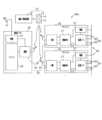
図1は、第1実施形態の電池監視装置95aを示す概略図である。電池監視装置95aは、直列に接続されている複数の電池モジュール91からなる組電池90を監視する。各電池モジュール91は、直列に接続された複数の単位電池92からなる。各単位電池92は、単体の電池セルであってもよいし、複数の電池セルの直列接続体であってもよい。組電池90及び電池監視装置95aは、いずれも車両に搭載されている。車両は、エンジン若しくはモータ又はその両方からなる走行用の動力装置を備えている。 [First embodiment]
1 is a schematic diagram showing a
電池監視装置95aは、電池ECU40と、電池モジュール91毎に設けられたサテライト20と、電池ECU40と各サテライト20との間で無線通信を行う無線モジュール30とを有する。車両は、キーレスエントリ装置10を備える。キーレスエントリ装置10は、コントローラ13と施錠/解錠装置18とを有する。コントローラ13は、施錠ボタン14と解錠ボタン15とを有し、施錠ボタン14が押されると無線で施錠信号を送信し、解錠ボタン15が押されると無線で解錠信号を送信する。施錠/解錠装置18は、施錠信号を受信すると車両のドアを施錠し、解錠信号を受信すると車両のドアを解錠する。The
無線モジュール30は、サテライト20に設けられている子機32と、電池ECU40に設けられている親機34とを有する。子機32は、サテライト20の本体部分の内側に設けられていてもよいし、サテライト20の本体部分の外側に設けられていてもよい。親機34は、電池ECU40の本体部分の内側に設けられていてもよいし、電池ECU40の本体部分の外側に設けられていてもよい。The
各サテライト20は、電源21と監視IC23とを有する。電源21は、電池モジュール91、監視IC23に接続されると共に、絶縁素子27を介して子機32に接続されている。電源21は、電池モジュール91から取得した電力を、監視IC23及び子機32に供給する。その電力により、監視IC23及び子機32が動作する。Each
監視IC23は、複数の単位電池92の各端子に接続されると共に、絶縁素子27を介して子機32に接続されている。絶縁素子27は、電源21及び監視IC23が高電圧帯の回路に形成され、子機32が低電圧帯の回路に形成されていることから、それら両者間の絶縁処理を行いつつ、電力や電気信号を伝達するために設けられている。The
電池ECU40は、電源47とマイコン43とを有する。電源47は、電池モジュール91とは別の電池98、マイコン43及び親機34に接続されており、電池98から取得した電力を、マイコン43及び親機34に供給する。その電力により、マイコン43及び親機34が動作する。The battery ECU 40 has a
マイコン43は、各サテライト20に対する指令を親機34に送信する。親機34は、その指令を各子機32に無線送信する。各子機32は、その指令を受信すると、その指令を監視IC23に送信する。監視IC23は、その指令に基づいて各単位電池92の端子間電圧や電池電流、セル温度等を検出したり、自己診断を実施したりし、その電圧データや電流データ、セル温度データ、自己診断結果等を子機32に送信する。子機32は、それらのデータを親機34に無線送信する。The
親機34は、それらのデータを受信すると、それらのデータをマイコン43に送信する。マイコン43は、それらのデータに基づいて、各単位電池92の内部抵抗及び充電状況(SOC)等を演算する。それにより、組電池90を監視する。When the
本実施形態では、キーレスエントリ装置10のコントローラ13からの解錠信号が、子機32及び親機34を起動させるための起動信号として作用する。詳しくは、車両の動力装置をOFFにした状態では、子機32及び親機34は、いずれも起動はしていないが、解錠信号は受信できるスタンバイの状態になっている。そして、子機32及び親機34は、それぞれ解錠信号を受信すると起動して、相手方との無線接続を開始する。In this embodiment, the unlock signal from the
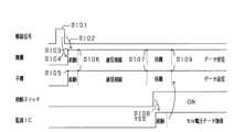
図2は、解錠信号を発信してから無線接続が完了するまでの流れを示すフローチャートである。また、図3は、同流れを示すタイムチャートである。まず、ドライバー等がコントローラ13の解錠ボタン15を押すことにより、解錠信号が発信される(S101)。その解錠信号を親機34が受信すること(S102)により親機34が起動を開始する(S103)。また、その解錠信号を子機32が受信すること(S104)により、子機32が起動を開始する(S105)。その後、起動した親機34と子機32とが無線接続を開始して(S106)、その後、無線接続を完了させる(S107)。その後、親機34及び子機32は待機する。Figure 2 is a flow chart showing the flow from when an unlock signal is sent to when a wireless connection is completed. Figure 3 is a time chart showing the same flow. First, the driver or the like presses the
その後、所定の判定装置が、動力装置の始動スイッチがONになったか否かを判定する(S108)。ONになっていない場合(S108:NO)、同判定を繰り返す。ONになった場合(S108:YES)、判定装置は、各監視IC23に所定の信号を有線又は無線で送信することにより、各監視IC23を起動させる。起動した監視IC23は、単位電池92の端子間電圧や電池電流、セル温度等を検出したり、自己診断を実施したりし、それらのデータを子機32に送信する。子機32はそれらのデータを親機34に無線送信する。これにより、子機32と親機34との無線通信を開始され(S109)、監視IC23とマイコン43との通信が開始される。マイコン43から監視IC23へは、指令等が送信される。他方、監視IC23からマイコン43へは、電圧データ等が送信される。After that, a predetermined determination device determines whether the start switch of the power unit is ON (S108). If it is not ON (S108: NO), the same determination is repeated. If it is ON (S108: YES), the determination device starts each monitoring
なお、上記では、S108で動力装置の始動スイッチがONになったか否かを判定し、ONになった場合には、無線通信を開始する態様を示したが、これに代えて、図4に示すように、S108でドライバーが運転席に着座したか否かを判定し、着座したと判定した場合には、無線通信を開始するようにしてもよい。In the above, it is determined in S108 whether the start switch of the power unit is ON, and if so, wireless communication is started. Alternatively, as shown in FIG. 4, it may be determined in S108 whether the driver is seated in the driver's seat, and if it is determined that the driver is seated, wireless communication is started.
本実施形態によれば、次の効果を得ることができる。通信の無線化によりハーネスの配置スペースを削減できる。また、動力装置の始動スイッチをONにするよりも前に、キーレスエントリ装置10の解錠信号により無線モジュール30を起動させて、無線接続を開始させることができる。そのため、動力装置の始動スイッチをONにすると同時に無線モジュール30を起動させる場合よりも早く、無線接続を開始して、その場合よりも早く無線接続を完了させることができる。そのため、速やかに組電池90の監視を開始できる。その結果、速やかに車両を発進させることができる。According to this embodiment, the following effects can be obtained. By making the communication wireless, the space required for arranging the harness can be reduced. In addition, the
また、無線モジュール30を起動させる起動信号は、キーレスエントリ装置10の解錠信号であるため、ドライバーが車両から離れている比較的早い時期に、解錠信号により無線モジュール30を起動させて、無線接続を開始できる。そのため、無線接続を開始してから動力装置の始動スイッチをONにするまでの間の時間を、長く確保することができる。そのため、無線接続に長い時間がかかる場合等にも、動力装置の始動スイッチをONにするまでに、無線接続を完了させ易くなる。そのため、動力装置の始動スイッチをONにした後、速やかに電池セルの監視を開始し易くなる。In addition, since the activation signal that activates the
また、親機34及び子機32の両方が解錠信号を受信して起動するので、この点でも、速やかに無線接続を開始できる。In addition, both the
次に第1実施形態以外の実施形態について説明する。以下の実施形態では、それ以前の実施形態のものと同一の又は対応する部材等は、同一の符号を付して、第1実施形態と異なる点のみを説明する。ただし、電池監視装置については、実施形態毎に異なる符号を付する。Next, embodiments other than the first embodiment will be described. In the following embodiments, components that are the same as or correspond to those in the previous embodiments will be given the same reference numerals, and only the differences from the first embodiment will be described. However, the battery monitoring device will be given a different reference numeral for each embodiment.
[第2実施形態]
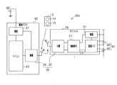
図5を参照しつつ、第2実施形態の電池監視装置95bについて説明する。親機34及び子機32は、いずれも解錠信号を受信する構成及び機能を有していない。親機34は、車両の動力装置をOFFにした状態では、起動しておらず、また、無線信号を受信可能なスタンバイの状態にもなっていない。他方、子機32は、車両の動力装置をOFFにした状態では、起動はしていないが、親機34からの無線信号は受信できるスタンバイの状態になっている。 [Second embodiment]
A
電池監視装置95bの電池ECU40には、電源47と親機34とを接続する配線上にスイッチ41が設けられている。施錠/解錠装置18は、コントローラ13からの解錠信号を受信すると、車両のドアを解錠すると共にCAN42を通じてマイコン43に所定の信号を送信する。マイコン43は、その信号を受信するとスイッチ41をONにすることにより、親機34を起動させる。起動した親機34は、子機32に無線信号を送信することにより、子機32を起動させる。The
本実施形態によれば、次の効果が得られる。マイコン43がスイッチ41をONにすることにより親機34を起動させるため、親機34は、解錠信号を受信可能な状態でスタンバイしていなくても、起動することができる。そのため、親機34のスタンバイに要する暗電流さえも削減できる。According to this embodiment, the following effects can be obtained. Because the
また、親機34が子機32に無線信号を送信することにより子機32を起動させるため、子機32については、親機34からの無線信号のみ受信可能であればよく、解錠信号を受信可能である必要がない。そのため、子機32の機能及び構成をシンプルにできる。In addition, since the
[第3実施形態]
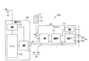
図6を参照しつつ、第3実施形態の電池監視装置95cについて説明する。子機32は、第2実施形態と同様、解錠信号を受信する構成及び機能を有していない。親機34は、解錠信号を受信して起動してから、子機32に無線信号を送信することにより、子機32を起動させる。 [Third embodiment]
A
本実施形態によれば、親機34が解錠信号を受信する態様において、第2実施形態と同様、子機32の機能及び構成をシンプルにできる。According to this embodiment, when the
[第4実施形態]
図7を参照しつつ、第4実施形態の電池監視装置95dについて説明する。親機34は、解錠信号を受信する構成及び機能を有していない。子機32は、解錠信号を受信して起動してから、親機34に無線信号を送信することにより、親機34を起動させる。 [Fourth embodiment]
A
本実施形態によれば、子機32が親機34に無線信号を送信することにより親機34を起動させるため、親機34については、子機32からの無線信号のみ受信可能であればよく、解錠信号を受信可能である必要がない。そのため、親機34の機能及び構成をシンプルにできる。According to this embodiment, the
[第5実施形態]
次に、図8を参照しつつ、第5実施形態の電池監視装置95eについて説明する。本実施形態では、電池監視装置95eは、親機34を複数有する。各親機34は、自身に対応する単数又は複数の子機32が定められており、その自身に対応する子機32に無線信号を送信する。子機32は、自身に対応する親機34からの無線信号の受信により起動して、その自身に対応する親機34と無線接続を開始する。 [Fifth embodiment]
Next, a
本実施形態によれば、複数の各親機34が、自身に対応する子機32に無線信号を送信するため、各親機34の子機32を起動させる負担が軽減される。また、複数の各親機34が、自身に対応する子機32と無線接続をするため、各親機34の無線接続に要する負担が軽減される。以上により、子機32の数が多い場合にも、親機34と子機32との無線接続を速やかに完了させることができる。According to this embodiment, each of the
[その他の実施形態]
各実施形態は、次のように変更して実施することもできる。例えば、各実施形態において、解錠信号の代わりに、それとは別の無線信号又は有線信号により、無線モジュール30を起動させるようにしてもよい。 [Other embodiments]
Each embodiment may be modified as follows: For example, in each embodiment, the
具体的には、例えば、車両のドアを開くと、無線モジュール30を起動させるための起動信号が、親機34、子機32、マイコン43又は監視IC23等に、有線又は無線で送信されるようにしてもよい。また例えば、人感センサが人影を感知すると、無線モジュール30を起動させるための起動信号が、親機34、子機32、マイコン43又は監視IC23等に、有線又は無線で送信されるようにしてもよい。また例えば、ドライバーが運転席に座ると、無線モジュール30を起動させるための起動信号が、親機34、子機32、マイコン43又は監視IC23等に、有線又は無線で送信されるようにしてもよい。Specifically, for example, when the door of the vehicle is opened, an activation signal for activating the
また例えば、図5に示す第2実施形態等において、電池ECU40の電源47と親機34とを接続する配線上にスイッチ41を設ける代わりに、サテライト20の電源21と子機32とを接続する配線上にスイッチを設けてもよい。そして、解錠信号を施錠/解錠装置18が受信すると、施錠/解錠装置18は、CANを通じて監視IC23に信号を送信し、監視IC23は、その信号を受信するとスイッチをONにすることにより、子機32を起動させるようにしてもよい。そして、起動した子機32が親機34に無線信号を送信することにより、親機34を起動させるようにしてもよい。For example, in the second embodiment shown in FIG. 5, instead of providing a switch 41 on the wiring connecting the
また例えば、図7に示す第4実施形態において、いずれか1つの子機32のみが解錠信号を受信し、その子機32が親機34に無線信号を送信することにより親機34を起動させ、親機34が、その子機32以外の各子機32に無線信号を送信することにより、各子機32を起動させるようにしてもよい。For example, in the fourth embodiment shown in FIG. 7, only one of the
また例えば、図8に示す第5実施形態において、初期状態においては、各親機34は、自身に対応する子機32が定められておらず、各親機34は、自身に対応する子機32の台数のみが定められているようにしてもよい。そして、各親機34は、自身が送信した無線信号を受信した子機32又は自身が受信した無線信号を送信した子機32であって、未だ他の親機34を自身の親機34としていない子機32を、上記台数だけ自身に対応する子機32と定めて、その子機32と無線接続をするようにしてもよい。Also, for example, in the fifth embodiment shown in FIG. 8, in the initial state, each
20…サテライト、30…無線モジュール、40…電池ECU、95a~95e…電池監視装置。20...satellite, 30...wireless module, 40...battery ECU, 95a to 95e...battery monitoring device.
Claims (11)
Translated fromJapanese複数の親機(34)、及び複数の前記親機それぞれに対して前記電池セルの電圧を検出する旨の指令を送信するマイコン(43)を有する電池ECU(40)と、
子機(32)を有し、前記子機を介して前記マイコンの指令を受信することにより、前記電池セルの電圧を検出する複数のサテライト(20)と、を備え、
複数の前記親機は、前記マイコンに並列に接続されており、
複数の前記親機のそれぞれは、複数の前記子機に、前記マイコンの指令を送信可能である、電池監視装置。 A battery monitoring device (95a to 95e) for monitoring a battery cell mounted on a vehicle,
a battery ECU (40) having a plurality of parent units (34) and a microcomputer (43) for transmitting a command to each of the plurality of parent units to detect the voltage of the battery cell;
a plurality of satellites (20) each having a child device (32) and detecting the voltage of the battery cell by receiving a command from the microcomputer via the child device;
The plurality of parent devices are connected in parallel to the microcomputer,
A battery monitoring device, wherein each of the plurality of parent devices is capable of transmitting commands of the microcomputer to the plurality of child devices.
前記親機は、前記無線モジュールを起動させるための起動信号を受信し、前記無線モジュールを起動させる、請求項1に記載の電池監視装置。 The parent device and the child device constitute a wireless module (30) for wirelessly communicating betweenthe battery ECU and the satellite,
The battery monitoring device according to claim 1 , wherein the master unit receives a start-up signal for starting the wireless module, and starts up the wireless module.
前記起動信号は前記解錠信号である、請求項8に記載の電池監視装置。 The vehicle is equipped with a keyless entry device (10) having a controller (13) and an unlocking device (18) that unlocks a door of the vehicle in response to an unlocking signal from the controller,
The battery monitoring device according to claim8 , wherein the activation signal is the unlock signal.
前記サテライトに設けられ、前記電池セルの電圧を検出する旨の指令を受信する子機(32)と、を有する電池監視装置(95a~95e)に適用される電池ECU(40)において、
複数の親機(34)と、
複数の前記親機それぞれに対して前記電池セルの電圧を検出する旨の指令を送信するマイコン(43)と、備え、
複数の前記親機は、前記マイコンに並列に接続されており、
複数の前記親機のそれぞれは、複数の前記子機に、前記マイコンの指令を送信可能である、電池ECU。 A satellite (20) for detecting the voltage of a battery cell mounted on a vehicle;
A battery ECU (40) applied to a battery monitoring device (95a to 95e) having a child device (32) provided in the satellite and configured to receive a command to detect the voltage of the battery cell,
A plurality of parent units (34);
a microcomputer (43) for transmitting a command to each of the plurality of parent devices to detect the voltage of the battery cell;
The plurality of parent devices are connected in parallel to the microcomputer,
Each of the plurality of parent devices is capable of transmitting a command of the microcomputer to the plurality of child devices.
Priority Applications (1)
| Application Number | Priority Date | Filing Date | Title |
|---|---|---|---|
| JP2022126955AJP7472940B2 (en) | 2018-11-05 | 2022-08-09 | Battery monitoring device, battery ECU, and satellite |
Applications Claiming Priority (2)
| Application Number | Priority Date | Filing Date | Title |
|---|---|---|---|
| JP2018208341AJP7127494B2 (en) | 2018-11-05 | 2018-11-05 | battery monitor |
| JP2022126955AJP7472940B2 (en) | 2018-11-05 | 2022-08-09 | Battery monitoring device, battery ECU, and satellite |
Related Parent Applications (1)
| Application Number | Title | Priority Date | Filing Date |
|---|---|---|---|
| JP2018208341ADivisionJP7127494B2 (en) | 2018-11-05 | 2018-11-05 | battery monitor |
Publications (3)
| Publication Number | Publication Date |
|---|---|
| JP2022167915A JP2022167915A (en) | 2022-11-04 |
| JP2022167915A5 JP2022167915A5 (en) | 2023-06-20 |
| JP7472940B2true JP7472940B2 (en) | 2024-04-23 |
Family
ID=70458534
Family Applications (2)
| Application Number | Title | Priority Date | Filing Date |
|---|---|---|---|
| JP2018208341AActiveJP7127494B2 (en) | 2018-11-05 | 2018-11-05 | battery monitor |
| JP2022126955AActiveJP7472940B2 (en) | 2018-11-05 | 2022-08-09 | Battery monitoring device, battery ECU, and satellite |
Family Applications Before (1)
| Application Number | Title | Priority Date | Filing Date |
|---|---|---|---|
| JP2018208341AActiveJP7127494B2 (en) | 2018-11-05 | 2018-11-05 | battery monitor |
Country Status (2)
| Country | Link |
|---|---|
| US (3) | US11333709B2 (en) |
| JP (2) | JP7127494B2 (en) |
Families Citing this family (16)
| Publication number | Priority date | Publication date | Assignee | Title |
|---|---|---|---|---|
| FR2650156A1 (en) | 1989-07-26 | 1991-02-01 | Bizet Andre | THANATOPRAXIC LIQUID |
| JP7127494B2 (en)* | 2018-11-05 | 2022-08-30 | 株式会社デンソー | battery monitor |
| JP7077996B2 (en)* | 2019-03-04 | 2022-05-31 | 株式会社デンソー | ID allocation system and ID allocation method |
| WO2021163500A1 (en) | 2020-02-14 | 2021-08-19 | Sensata Technologies, Inc. | Communication in a wireless battery management system for a battery pack structure |
| US11909007B2 (en) | 2020-07-31 | 2024-02-20 | Volvo Car Corporation | Intelligent battery cell with integrated monitoring and switches |
| US11961978B2 (en) | 2020-07-31 | 2024-04-16 | Volvo Car Corporation | Integrated alternating current and direct current supply in a battery device |
| CN116235340A (en) | 2020-09-24 | 2023-06-06 | 森萨塔科技公司 | Signal transmission system and method through battery cell for in-battery sensing |
| CN114597985A (en) | 2020-12-03 | 2022-06-07 | 麦太保有限公司 | Battery pack, battery-operated device, external charger, and method of configuration |
| JP7609043B2 (en)* | 2021-02-24 | 2025-01-07 | 株式会社デンソー | Battery Management System |
| EP4056402A1 (en) | 2021-03-10 | 2022-09-14 | Volvo Truck Corporation | A safety system for detecting a critical condition in a battery pack |
| JP7649665B2 (en) | 2021-03-11 | 2025-03-21 | プライムプラネットエナジー&ソリューションズ株式会社 | Energy storage cell |
| US20220341998A1 (en) | 2021-04-23 | 2022-10-27 | Schneider Electric It Corporation | Wireless monitoring and management of ups battery modules and other accessories |
| JP7548166B2 (en) | 2021-08-31 | 2024-09-10 | 株式会社デンソー | Battery Monitoring System |
| US11942609B2 (en)* | 2021-10-29 | 2024-03-26 | Texas Instruments Incorporated | Reduced power wireless battery management system |
| CN115103335B (en)* | 2022-07-20 | 2025-02-25 | 深圳市科运智联科技有限公司 | A monitoring device for separation of automobile head and trailer |
| US12382831B2 (en)* | 2022-07-20 | 2025-08-05 | University Of Malta | Multilevel thermoelectric cooling stack with thermal guard rings |
Citations (2)
| Publication number | Priority date | Publication date | Assignee | Title |
|---|---|---|---|---|
| WO2013051157A1 (en) | 2011-10-07 | 2013-04-11 | 日立ビークルエナジー株式会社 | Battery monitoring system, host controller, and battery monitoring device |
| JP2018058379A (en) | 2015-02-20 | 2018-04-12 | パナソニックIpマネジメント株式会社 | Battery condition measurement device and control method |
Family Cites Families (31)
| Publication number | Priority date | Publication date | Assignee | Title |
|---|---|---|---|---|
| US5469861A (en)* | 1992-04-17 | 1995-11-28 | Mark F. Piscopo | Posture monitor |
| JPH07246915A (en)* | 1994-03-10 | 1995-09-26 | Alpine Electron Inc | On-vehicle receiving device |
| JP4350864B2 (en)* | 2000-03-01 | 2009-10-21 | アルプス電気株式会社 | Keyless entry device |
| DE10202332B4 (en)* | 2002-01-23 | 2011-08-11 | Marquardt GmbH, 78604 | Locking system, in particular for a motor vehicle |
| US6819229B2 (en)* | 2002-06-03 | 2004-11-16 | Lear Corporation | Countermeasure system and method for vehicle passive entry system |
| JP4137657B2 (en)* | 2003-02-06 | 2008-08-20 | 株式会社東海理化電機製作所 | Engine start / stop switch device |
| JP2005001452A (en)* | 2003-06-10 | 2005-01-06 | Tokai Rika Co Ltd | Vehicular power control device |
| US7672666B2 (en)* | 2004-03-03 | 2010-03-02 | Alcatel-Lucent Usa Inc. | Method and system for implementing vehicle functions through a mobile communication device |
| WO2006015418A1 (en)* | 2004-08-10 | 2006-02-16 | Australian Arrow Pty Ltd | Bi-directional radio monitoring system |
| JP5503924B2 (en)* | 2009-08-27 | 2014-05-28 | 矢崎総業株式会社 | Multi-battery battery status monitoring unit |
| JP5436255B2 (en)* | 2010-02-12 | 2014-03-05 | 富士通テン株式会社 | Remote starter |
| US8692663B2 (en)* | 2010-08-10 | 2014-04-08 | General Motors Llc. | Wireless monitoring of battery for lifecycle management |
| US20120286927A1 (en)* | 2011-05-12 | 2012-11-15 | Andreas Hagl | Wake Channel Indication for Passive Entry System |
| US8769327B2 (en)* | 2011-10-04 | 2014-07-01 | Advanergy, Inc. | Battery charger management system and method for controlling a charge current by indirectly determining the type and characteristics of a battery via a current consumed by a charger |
| JP2013140055A (en)* | 2011-12-29 | 2013-07-18 | Toyota Central R&D Labs Inc | Battery monitoring system |
| JP5880394B2 (en)* | 2012-10-30 | 2016-03-09 | トヨタ自動車株式会社 | Vehicle power supply |
| JP6093448B2 (en) | 2013-11-01 | 2017-03-08 | 株式会社日立製作所 | Battery control system |
| JP6391137B2 (en)* | 2013-12-24 | 2018-09-19 | 株式会社中野エンジニアリング | Through-type interlocking lighting system |
| JP2016082844A (en)* | 2014-10-22 | 2016-05-16 | トヨタ自動車株式会社 | vehicle |
| US9725069B2 (en)* | 2015-10-12 | 2017-08-08 | Ford Global Technologies, Llc | Keyless vehicle systems |
| CN107305372B (en)* | 2016-04-25 | 2020-06-19 | 岳秀兰 | Electric automobile energy monitoring and supply network for remote monitoring of cloud computing network architecture |
| US10043329B2 (en)* | 2016-09-28 | 2018-08-07 | Ford Global Technologies, Llc | Detection and protection against jam intercept and replay attacks |
| JP6916983B2 (en)* | 2016-11-01 | 2021-08-11 | 株式会社オートネットワーク技術研究所 | Battery monitoring system for vehicles |
| US10401937B2 (en)* | 2017-02-14 | 2019-09-03 | GM Global Technology Operations LLC | Method and apparatus for detection of battery drain |
| KR102392017B1 (en)* | 2017-11-06 | 2022-05-02 | 현대자동차주식회사 | Server, Vehicle communicating with the server and method for controlling the server |
| US20190306592A1 (en)* | 2018-03-29 | 2019-10-03 | Veoneer Us Inc. | Wireless satellite sensor |
| US11395119B2 (en)* | 2018-09-13 | 2022-07-19 | Lg Electronics Inc. | Wireless battery management system for vehicle |
| CN109127539A (en)* | 2018-09-18 | 2019-01-04 | 江苏苏美达五金工具有限公司 | It is remotely controlled gasoline cleaner |
| JP2020053176A (en)* | 2018-09-25 | 2020-04-02 | 株式会社デンソー | Battery monitoring system |
| JP7127494B2 (en)* | 2018-11-05 | 2022-08-30 | 株式会社デンソー | battery monitor |
| JP7247543B2 (en)* | 2018-11-22 | 2023-03-29 | トヨタ自動車株式会社 | vehicle |
- 2018
- 2018-11-05JPJP2018208341Apatent/JP7127494B2/enactiveActive
- 2019
- 2019-11-05USUS16/674,074patent/US11333709B2/enactiveActive
- 2022
- 2022-04-14USUS17/720,768patent/US11906588B2/enactiveActive
- 2022-08-09JPJP2022126955Apatent/JP7472940B2/enactiveActive
- 2023
- 2023-08-24USUS18/237,637patent/US12270859B2/enactiveActive
Patent Citations (2)
| Publication number | Priority date | Publication date | Assignee | Title |
|---|---|---|---|---|
| WO2013051157A1 (en) | 2011-10-07 | 2013-04-11 | 日立ビークルエナジー株式会社 | Battery monitoring system, host controller, and battery monitoring device |
| JP2018058379A (en) | 2015-02-20 | 2018-04-12 | パナソニックIpマネジメント株式会社 | Battery condition measurement device and control method |
Also Published As
| Publication number | Publication date |
|---|---|
| US20230393207A1 (en) | 2023-12-07 |
| JP2022167915A (en) | 2022-11-04 |
| JP2020078115A (en) | 2020-05-21 |
| US20220236330A1 (en) | 2022-07-28 |
| US12270859B2 (en) | 2025-04-08 |
| US11333709B2 (en) | 2022-05-17 |
| US11906588B2 (en) | 2024-02-20 |
| US20200142004A1 (en) | 2020-05-07 |
| JP7127494B2 (en) | 2022-08-30 |
Similar Documents
| Publication | Publication Date | Title |
|---|---|---|
| JP7472940B2 (en) | Battery monitoring device, battery ECU, and satellite | |
| JP2022167915A5 (en) | ||
| KR102690900B1 (en) | Charging control apparatus for electric vehicle | |
| US10475267B2 (en) | Vehicle finder card with a thin film battery | |
| US20100312417A1 (en) | Vehicle-mounted electronic system | |
| CN110576811A (en) | System and method for avoiding battery depletion in parked vehicles | |
| US9789771B2 (en) | Single battery architecture for electrification vehicle | |
| US20150188345A1 (en) | Vehicle door | |
| CN109774532A (en) | Vehicles and Electrical Equipment | |
| CN111409477A (en) | Vehicle with a steering wheel | |
| CN112112958B (en) | Vehicle power-on and power-off control method, vehicle and computer-readable storage medium | |
| JP2008224522A (en) | Antenna connection diagnosis device | |
| US12330503B2 (en) | Power supply control method and power supply control device | |
| CN107571941A (en) | A kind of one-key start safety device of electric vehicle and electric car | |
| JP4364764B2 (en) | Electric steering lock device | |
| US11230176B2 (en) | Battery system for use on a vehicle electrical system of a motor vehicle | |
| US20060012941A1 (en) | Method for operating an electronic module supplied with electrical energy by an operating voltage source | |
| CN214607387U (en) | Automobile body controller and vehicle | |
| CN116238457A (en) | A keyless start system and method shared by low-frequency antenna and IMMO antenna in vehicle | |
| CN115891880A (en) | Method, system and device for controlling electric quantity of battery in vehicle and vehicle | |
| JP7165026B2 (en) | Charge/discharge control method and charge/discharge device | |
| JP2000329041A (en) | Engine starting control device | |
| JP2022157418A (en) | Vehicle door latch device | |
| EP1246742B1 (en) | Alarm system for a motor vehicle | |
| JP7463814B2 (en) | Vehicle Battery System |
Legal Events
| Date | Code | Title | Description |
|---|---|---|---|
| A621 | Written request for application examination | Free format text:JAPANESE INTERMEDIATE CODE: A621 Effective date:20220809 | |
| A521 | Request for written amendment filed | Free format text:JAPANESE INTERMEDIATE CODE: A523 Effective date:20230612 | |
| A977 | Report on retrieval | Free format text:JAPANESE INTERMEDIATE CODE: A971007 Effective date:20230814 | |
| A131 | Notification of reasons for refusal | Free format text:JAPANESE INTERMEDIATE CODE: A131 Effective date:20230822 | |
| A521 | Request for written amendment filed | Free format text:JAPANESE INTERMEDIATE CODE: A523 Effective date:20231004 | |
| A02 | Decision of refusal | Free format text:JAPANESE INTERMEDIATE CODE: A02 Effective date:20240109 | |
| A521 | Request for written amendment filed | Free format text:JAPANESE INTERMEDIATE CODE: A523 Effective date:20240208 | |
| A911 | Transfer to examiner for re-examination before appeal (zenchi) | Free format text:JAPANESE INTERMEDIATE CODE: A911 Effective date:20240215 | |
| TRDD | Decision of grant or rejection written | ||
| A01 | Written decision to grant a patent or to grant a registration (utility model) | Free format text:JAPANESE INTERMEDIATE CODE: A01 Effective date:20240312 | |
| A61 | First payment of annual fees (during grant procedure) | Free format text:JAPANESE INTERMEDIATE CODE: A61 Effective date:20240325 | |
| R150 | Certificate of patent or registration of utility model | Ref document number:7472940 Country of ref document:JP Free format text:JAPANESE INTERMEDIATE CODE: R150 |