JP7472263B2 - Robot arm with extendable prism links - Google Patents
Robot arm with extendable prism linksDownload PDFInfo
- Publication number
- JP7472263B2 JP7472263B2JP2022506162AJP2022506162AJP7472263B2JP 7472263 B2JP7472263 B2JP 7472263B2JP 2022506162 AJP2022506162 AJP 2022506162AJP 2022506162 AJP2022506162 AJP 2022506162AJP 7472263 B2JP7472263 B2JP 7472263B2
- Authority
- JP
- Japan
- Prior art keywords
- link
- axis
- joint
- sub
- prismatic
- Prior art date
- Legal status (The legal status is an assumption and is not a legal conclusion. Google has not performed a legal analysis and makes no representation as to the accuracy of the status listed.)
- Active
Links
Images


Classifications
- A—HUMAN NECESSITIES
- A61—MEDICAL OR VETERINARY SCIENCE; HYGIENE
- A61B—DIAGNOSIS; SURGERY; IDENTIFICATION
- A61B34/00—Computer-aided surgery; Manipulators or robots specially adapted for use in surgery
- A61B34/30—Surgical robots
- A—HUMAN NECESSITIES
- A61—MEDICAL OR VETERINARY SCIENCE; HYGIENE
- A61B—DIAGNOSIS; SURGERY; IDENTIFICATION
- A61B34/00—Computer-aided surgery; Manipulators or robots specially adapted for use in surgery
- A61B34/30—Surgical robots
- A61B34/35—Surgical robots for telesurgery
- A—HUMAN NECESSITIES
- A61—MEDICAL OR VETERINARY SCIENCE; HYGIENE
- A61B—DIAGNOSIS; SURGERY; IDENTIFICATION
- A61B34/00—Computer-aided surgery; Manipulators or robots specially adapted for use in surgery
- A61B34/20—Surgical navigation systems; Devices for tracking or guiding surgical instruments, e.g. for frameless stereotaxis
- A—HUMAN NECESSITIES
- A61—MEDICAL OR VETERINARY SCIENCE; HYGIENE
- A61B—DIAGNOSIS; SURGERY; IDENTIFICATION
- A61B34/00—Computer-aided surgery; Manipulators or robots specially adapted for use in surgery
- A61B34/25—User interfaces for surgical systems
- A—HUMAN NECESSITIES
- A61—MEDICAL OR VETERINARY SCIENCE; HYGIENE
- A61B—DIAGNOSIS; SURGERY; IDENTIFICATION
- A61B34/00—Computer-aided surgery; Manipulators or robots specially adapted for use in surgery
- A61B34/70—Manipulators specially adapted for use in surgery
- A61B34/77—Manipulators with motion or force scaling
- B—PERFORMING OPERATIONS; TRANSPORTING
- B25—HAND TOOLS; PORTABLE POWER-DRIVEN TOOLS; MANIPULATORS
- B25J—MANIPULATORS; CHAMBERS PROVIDED WITH MANIPULATION DEVICES
- B25J18/00—Arms
- B25J18/02—Arms extensible
- B—PERFORMING OPERATIONS; TRANSPORTING
- B25—HAND TOOLS; PORTABLE POWER-DRIVEN TOOLS; MANIPULATORS
- B25J—MANIPULATORS; CHAMBERS PROVIDED WITH MANIPULATION DEVICES
- B25J9/00—Programme-controlled manipulators
- B25J9/0009—Constructional details, e.g. manipulator supports, bases
- B25J9/0027—Means for extending the operation range
- B—PERFORMING OPERATIONS; TRANSPORTING
- B25—HAND TOOLS; PORTABLE POWER-DRIVEN TOOLS; MANIPULATORS
- B25J—MANIPULATORS; CHAMBERS PROVIDED WITH MANIPULATION DEVICES
- B25J9/00—Programme-controlled manipulators
- B25J9/06—Programme-controlled manipulators characterised by multi-articulated arms
- B—PERFORMING OPERATIONS; TRANSPORTING
- B25—HAND TOOLS; PORTABLE POWER-DRIVEN TOOLS; MANIPULATORS
- B25J—MANIPULATORS; CHAMBERS PROVIDED WITH MANIPULATION DEVICES
- B25J9/00—Programme-controlled manipulators
- B25J9/16—Programme controls
- B25J9/1679—Programme controls characterised by the tasks executed
- B25J9/1689—Teleoperation
- A—HUMAN NECESSITIES
- A61—MEDICAL OR VETERINARY SCIENCE; HYGIENE
- A61B—DIAGNOSIS; SURGERY; IDENTIFICATION
- A61B17/00—Surgical instruments, devices or methods
- A61B2017/00017—Electrical control of surgical instruments
- A61B2017/00199—Electrical control of surgical instruments with a console, e.g. a control panel with a display
- A—HUMAN NECESSITIES
- A61—MEDICAL OR VETERINARY SCIENCE; HYGIENE
- A61B—DIAGNOSIS; SURGERY; IDENTIFICATION
- A61B17/00—Surgical instruments, devices or methods
- A61B2017/00017—Electrical control of surgical instruments
- A61B2017/00216—Electrical control of surgical instruments with eye tracking or head position tracking control
- A—HUMAN NECESSITIES
- A61—MEDICAL OR VETERINARY SCIENCE; HYGIENE
- A61B—DIAGNOSIS; SURGERY; IDENTIFICATION
- A61B17/00—Surgical instruments, devices or methods
- A61B2017/00477—Coupling
- A—HUMAN NECESSITIES
- A61—MEDICAL OR VETERINARY SCIENCE; HYGIENE
- A61B—DIAGNOSIS; SURGERY; IDENTIFICATION
- A61B17/00—Surgical instruments, devices or methods
- A61B2017/00973—Surgical instruments, devices or methods pedal-operated
- A—HUMAN NECESSITIES
- A61—MEDICAL OR VETERINARY SCIENCE; HYGIENE
- A61B—DIAGNOSIS; SURGERY; IDENTIFICATION
- A61B17/00—Surgical instruments, devices or methods
- A61B2017/00982—General structural features
- A61B2017/00991—Telescopic means
- A—HUMAN NECESSITIES
- A61—MEDICAL OR VETERINARY SCIENCE; HYGIENE
- A61B—DIAGNOSIS; SURGERY; IDENTIFICATION
- A61B34/00—Computer-aided surgery; Manipulators or robots specially adapted for use in surgery
- A61B34/20—Surgical navigation systems; Devices for tracking or guiding surgical instruments, e.g. for frameless stereotaxis
- A61B2034/2046—Tracking techniques
- A61B2034/2051—Electromagnetic tracking systems
- A—HUMAN NECESSITIES
- A61—MEDICAL OR VETERINARY SCIENCE; HYGIENE
- A61B—DIAGNOSIS; SURGERY; IDENTIFICATION
- A61B34/00—Computer-aided surgery; Manipulators or robots specially adapted for use in surgery
- A61B34/20—Surgical navigation systems; Devices for tracking or guiding surgical instruments, e.g. for frameless stereotaxis
- A61B2034/2046—Tracking techniques
- A61B2034/2055—Optical tracking systems
- A—HUMAN NECESSITIES
- A61—MEDICAL OR VETERINARY SCIENCE; HYGIENE
- A61B—DIAGNOSIS; SURGERY; IDENTIFICATION
- A61B34/00—Computer-aided surgery; Manipulators or robots specially adapted for use in surgery
- A61B34/30—Surgical robots
- A61B2034/305—Details of wrist mechanisms at distal ends of robotic arms
- B—PERFORMING OPERATIONS; TRANSPORTING
- B25—HAND TOOLS; PORTABLE POWER-DRIVEN TOOLS; MANIPULATORS
- B25J—MANIPULATORS; CHAMBERS PROVIDED WITH MANIPULATION DEVICES
- B25J9/00—Programme-controlled manipulators
- B25J9/003—Programme-controlled manipulators having parallel kinematics
- B25J9/0033—Programme-controlled manipulators having parallel kinematics with kinematics chains having a prismatic joint at the base
- B25J9/0039—Programme-controlled manipulators having parallel kinematics with kinematics chains having a prismatic joint at the base with kinematics chains of the type prismatic-spherical-spherical
Landscapes
- Engineering & Computer Science (AREA)
- Health & Medical Sciences (AREA)
- Life Sciences & Earth Sciences (AREA)
- Surgery (AREA)
- Robotics (AREA)
- Medical Informatics (AREA)
- Biomedical Technology (AREA)
- Heart & Thoracic Surgery (AREA)
- Nuclear Medicine, Radiotherapy & Molecular Imaging (AREA)
- Molecular Biology (AREA)
- Animal Behavior & Ethology (AREA)
- General Health & Medical Sciences (AREA)
- Public Health (AREA)
- Veterinary Medicine (AREA)
- Mechanical Engineering (AREA)
- Human Computer Interaction (AREA)
- Manipulator (AREA)
Description
Translated fromJapanese (関連出願の相互参照)
本出願は、2019年7月29日に出願された米国特許出願第16/525,427号の優先権の利益を主張するものであり、その全容が参照により本明細書に組み込まれる。 CROSS-REFERENCE TO RELATED APPLICATIONS
This application claims the benefit of priority to U.S. Patent Application No. 16/525,427, filed July 29, 2019, the entire contents of which are incorporated herein by reference.
(発明の分野)
ロボットシステムに関する実施形態が開示される。より具体的には、外科用ロボットシステム及び対応する機械的リンケージに関する実施形態が開示される。 FIELD OF THEINVENTION
Embodiments are disclosed that relate to robotic systems and, more particularly, to surgical robotic systems and corresponding mechanical linkages.
内視鏡手術は、患者の身体を調べて、内視鏡及び他の外科用ツールを使用して体内の手術を行うことを伴う。例えば、腹腔鏡手術は、腹腔鏡を使用して腹腔にアクセスし、それを視認することができる。内視鏡手術は、手動ツール、及び/又はロボット支援型ツールを有する外科用ロボットシステムを使用して行うことができる。Endoscopic surgery involves examining a patient's body and performing surgery inside the body using an endoscope and other surgical tools. For example, laparoscopic surgery can use a laparoscope to access and visualize the abdominal cavity. Endoscopic surgery can be performed using manual tools and/or surgical robotic systems with robot-assisted tools.
外科用ロボットシステムは、手術台に位置するロボット支援型ツールを制御するために、外科医によって遠隔操作され得る。外科用ツールは、患者の腹壁の切開部などの患者のアクセス点に挿入することができる。外科医は、手術室に位置する、又は異なる都市に位置し得るコンピュータコンソールを使用して、ロボットに命令して外科用ツールを操作し得る。ロボット制御式外科用ツールは、ロボットアーム上に装着することができ、コマンドは、外科用ツールがその周りを枢動する空間内の固定点である遠隔運動中心に外科用ツールを維持しながら、ロボットアームを移動させて、外科用ツールを患者の体内に位置付ける。遠隔運動中心は、患者のアクセス点と並置することができる。したがって、外科用ロボットシステムは、ロボット手術中にロボットアームを移動させることによって外科用ツールを患者の体内に位置付けるように、遠隔外科医によって制御され得る。The surgical robotic system may be remotely operated by a surgeon to control a robot-assisted tool located on the operating table. The surgical tool may be inserted into a patient access point, such as an incision in the patient's abdominal wall. The surgeon may command the robot to operate the surgical tool using a computer console that may be located in the operating room or in a different city. The robotically controlled surgical tool may be mounted on a robotic arm, and commands move the robotic arm to position the surgical tool within the patient's body while maintaining the surgical tool at a remote center of motion, which is a fixed point in space about which the surgical tool pivots. The remote center of motion may be collocated with the patient's access point. Thus, the surgical robotic system may be controlled by a remote surgeon to position the surgical tool within the patient's body by moving the robotic arm during robotic surgery.
ツールを遠隔運動中心に維持しながら外科用ツールを位置付けるために使用される既存のロボットアームは、ハードウェア拘束される。すなわち、ロボットアームは、所定の運動を与えるために互いに拘束される、固定長さのリンクを含む。例えば、ハードウェア拘束されたロボットアームは、単一のモータによって駆動され得る入力リンクの移動が、受動ジョイントによって入力リンクに接続されるいくつかの他の受動リンクの所定の移動を生じさせるように、平行四辺形に配設されたリンクを含むことができる。受動リンクの1つは、患者のアクセス点と並置された遠隔運動中心の周りで枢動するように拘束される出力リンクとすることができる。遠隔運動中心は、平行四辺形リンクの位置にかかわらず、空間内に固定されたままである。ハードウェア拘束されたロボットアームは、固定長さのリンクを必要とするが、これは、患者に対する所望の運動範囲を達成するために長くなる傾向がある。長い固定長さのリンクを必要とすることには、いくつかの課題を伴う。第1に、ハードウェア拘束されたロボットアームは、手術中に大きい空間体積をスイープするので、腕がぶつかることを回避しなければならない外科医又はサポートスタッフによる患者へのアクセスを抑制する場合がある。第2に、長い固定長さのリンクは、視覚的にも、並びに体積及び重量も大きい。したがって、リンクの慣性負荷が大きくなる場合があり、これは、嵩高くより高価なモータ及びジョイントの使用によって対応されなければならない。第3に、大きなサイズのリンクは、ハードウェア拘束されたリンケージの手術台の下への収容に好適でないものにする。代わりに、ロボットアームは、他の外科用器具及び操作者と共有されなければならない貴重な手術室空間である手術台の上側又は側面に格納されなければならない。Existing robotic arms used to position surgical tools while maintaining the tools at a remote center of motion are hardware constrained. That is, the robotic arm includes fixed-length links that are constrained to each other to provide a predetermined motion. For example, a hardware-constrained robotic arm may include links arranged in a parallelogram such that movement of an input link, which may be driven by a single motor, results in a predetermined movement of several other passive links that are connected to the input link by passive joints. One of the passive links may be an output link that is constrained to pivot about a remote center of motion juxtaposed with the patient's access point. The remote center of motion remains fixed in space regardless of the location of the parallelogram links. Hardware-constrained robotic arms require fixed-length links, which tend to be long to achieve a desired range of motion relative to the patient. Requiring long fixed-length links comes with several challenges. First, hardware-constrained robotic arms sweep a large volume of space during surgery and may inhibit access to the patient by the surgeon or support staff who must avoid hitting the arm. Second, long fixed-length links are large both visually as well as in volume and weight. Thus, the inertial loads of the links can be large, which must be accommodated by the use of bulkier and more expensive motors and joints. Third, the large size of the links makes the hardware-constrained linkage less suitable for storage under the operating table. Instead, the robotic arm must be stored above or to the side of the operating table, where valuable operating room space must be shared with other surgical instruments and operators.
互いに対してハードウェア拘束されないいくつかのジョイント又はリンクを有するソフトウェア制御のロボットアームを有する、外科用ツールを位置付けるためのロボットアームが提供される。各ジョイント又はリンクは、1つ又は2つ以上のそれぞれのモータによって能動的に駆動することができる。ジョイント又はリンクの1つ又は2つ以上は、プリズムジョイントを含むことができる。したがって、ジョイント又はリンクは、拡張可能であり得、様々な長さを有し得る。ソフトウェア制御のロボットアームは、ハードウェア拘束されたロボットアームと比較して、(少なくとも1つの構成で)より小さい空間エンベロープを占め得る。したがって、ロボットアームは、収容構成で手術台の下に収容するように折り畳むこと又はコンパクト化することができ、かつ能動構成に拡張して患者の上へ移動させることができる。ロボットアームのサイズ及び配向は、能動構成にある場合、別のロボットアーム又は外科医がぶつかるリスクと、外科手術のための特定の運動範囲に対する必要性とをバランスさせるように調整することができる。A robotic arm for positioning a surgical tool is provided, the robotic arm having a software-controlled robotic arm with several joints or links that are not hardware-constrained relative to each other. Each joint or link can be actively driven by one or more respective motors. One or more of the joints or links can include prismatic joints. Thus, the joints or links can be extendable and have a variety of lengths. The software-controlled robotic arm can occupy a smaller spatial envelope (in at least one configuration) compared to a hardware-constrained robotic arm. Thus, the robotic arm can be folded or compacted to fit under a surgical table in a stowed configuration and can be expanded to move over a patient in an active configuration. The size and orientation of the robotic arm can be adjusted to balance the risk of collision with another robotic arm or the surgeon when in the active configuration and the need for a particular range of motion for a surgical procedure.
一実施形態では、ロボットアームは、ロール軸を中心に回転可能であるロールジョイントと、外科用ツール及び/又はツールガイドを支持するよう構成されたツールドライブと、を含む。例えば、ツールドライブは、挿入軸に沿って外科用ツールのシャフトを受容することができるツールガイドに結合され得る。ロール軸及び挿入軸は、遠隔運動中心で交差する。外科用ツール及び/又はツールガイドは、挿入軸に沿って延在し、また、遠隔運動中心を通して挿入軸に沿って患者に挿入するように構成されている。ロボットアームは、遠隔運動中心を固定したままにするように移動可能である、いくつかのジョイント接続リンクを含むことができる。例えば、拡張可能なプリズムリンクは、それぞれのピッチジョイントにおいてロールジョイント及びツールドライブに接続することができる。例えば、ロールジョイントは、第1のピッチジョイントにおいてプリズムリンクに結合することができ、ツールドライブは、第2のピッチジョイントにおいてプリズムリンクに結合することができる。ツールドライブは、挿入軸に沿って移動可能であり得る結合位置において第2のピッチジョイントに結合することができる。拡張可能なプリズムリンクは、プリズムジョイントによって互いに接続されて、線形軸に沿って互いに対して摺動することができる、いくつかのプリズムサブリンクを含むことができる。プロセッサは、外科手術を行うために外科用ツールを前方又は後方にピッチさせるときに、ロボットアームのジョイント又はリンクの移動、例えば回転又は摺動を制御して、遠隔運動中心を固定したままにすることができる。In one embodiment, the robotic arm includes a roll joint that is rotatable about a roll axis and a tool drive configured to support a surgical tool and/or a tool guide. For example, the tool drive can be coupled to a tool guide that can receive a shaft of a surgical tool along an insertion axis. The roll axis and the insertion axis intersect at a remote center of motion. The surgical tool and/or tool guide extend along the insertion axis and are configured to be inserted into a patient along the insertion axis through the remote center of motion. The robotic arm can include several joint connecting links that are movable to keep the remote center of motion fixed. For example, an extendable prismatic link can be connected to the roll joint and the tool drive at a respective pitch joint. For example, the roll joint can be coupled to the prismatic link at a first pitch joint and the tool drive can be coupled to the prismatic link at a second pitch joint. The tool drive can be coupled to the second pitch joint at a coupling position that can be movable along the insertion axis. The extendable prismatic link can include several prismatic sub-links that are connected to each other by prismatic joints and can slide relative to each other along a linear axis. The processor can control the movement, e.g., rotation or sliding, of the joints or links of the robotic arm to keep the remote center of motion fixed when pitching the surgical tool forward or backward to perform a surgical procedure.
ロボットアームは、リンクを接続する様々なジョイントと関連付けられた1つ又は2つ以上のアクチュエータを含むことができる。例えば、第1のモータは、第1のピッチ軸の周りでプリズムリンクに対して回転するようにロールジョイントを駆動することができる。同様に、第2のモータは、第2のピッチ軸の周りでプリズムリンクに対して回転するようにツールドライブを駆動することができる。更に、第3のモータは、線形軸に沿って互いに対して摺動させるようにプリズムサブリンクを駆動することができる。モータは、リンクを別個に独立して駆動するように作動させることができ、したがって、リンクは、互いに対する運動を拘束しない。第1のピッチ軸、第2のピッチ軸、及び線形軸は、同じ平面内で挿入軸及びロール軸を維持する様式で配設することができる。例えば、第1のピッチ軸は、第2のピッチ軸に平行とすることができ、線形軸は、両方のピッチ軸に対して直角とすることができる。したがって、線形軸、ロール軸、及び挿入軸は、遠隔運動中心に位置する頂点を有する基準三角形を形成することができる。様々なモータを作動させることで、遠隔運動中心の位置に頂点を維持しながら、基準三角形の形状を変化させることができる。ロボットアームの幾何学形状が変化するときに、挿入軸は、患者の体内の外科用ツール先端部の運動範囲を画定する作業角度にわたりスイープすることができる。The robot arm may include one or more actuators associated with the various joints connecting the links. For example, a first motor may drive the roll joint to rotate relative to the prismatic link about a first pitch axis. Similarly, a second motor may drive the tool drive to rotate relative to the prismatic link about a second pitch axis. Additionally, a third motor may drive the prismatic sub-links to slide relative to each other along a linear axis. The motors may be actuated to drive the links separately and independently, so that the links are unconstrained in motion relative to each other. The first pitch axis, the second pitch axis, and the linear axis may be arranged in a manner that maintains the insertion axis and the roll axis in the same plane. For example, the first pitch axis may be parallel to the second pitch axis, and the linear axis may be perpendicular to both pitch axes. Thus, the linear axis, the roll axis, and the insertion axis may form a reference triangle with an apex located at the remote center of motion. By actuating the various motors, the shape of the reference triangle may be changed while maintaining the apex at the location of the remote center of motion. As the geometry of the robotic arm changes, the insertion axis can sweep through a working angle that defines the range of motion of the surgical tool tip within the patient.
作業角度は、ロボットアームのホーム構成に依存し得る。より具体的には、ロボットアームは、例えば基準三角形が直角三角形である場合、ロール軸が挿入軸に対して直角であるいくつかのホーム構成を有することができる。異なる直角三角形を形成するために、プリズムジョイントを延在させることができ、かつピッチジョイントを回転させることができるので、いくつかのホーム構成が存在する。そのホーム構成のための第1のピッチジョイントと遠隔運動中心との間の距離に基づいて、ホーム構成ごとに、作業角度が異なり得る。例えば、遠隔運動中心が、ロールジョイントをプリズムリンクに接続する第1のピッチジョイントからより遠くに移動するにつれて、作業角度は減少し得る。作業角度の調整は、患者の体内の外科用ツールの運動範囲と、リンケージと別のリンケージ又は患者の外側の操作者との衝突のリスクを低減させたいという望みとをバランスさせるように、適切なホーム構成を選択することによって選択することができる。The working angle may depend on the home configuration of the robot arm. More specifically, the robot arm may have several home configurations where the roll axis is at a right angle to the insertion axis, for example if the reference triangle is a right triangle. There are several home configurations because the prismatic joints can be extended and the pitch joints can be rotated to form different right triangles. For each home configuration, the working angle may be different based on the distance between the first pitch joint and the remote center of motion for that home configuration. For example, the working angle may decrease as the remote center of motion moves further from the first pitch joint that connects the roll joint to the prismatic link. Adjustments to the working angle may be selected by choosing the appropriate home configuration to balance the range of motion of the surgical tool inside the patient's body with the desire to reduce the risk of collision between the linkage and another linkage or an operator outside the patient.
一実施形態では、外科用ロボットシステムは、手術台上に装着されたロボットアームを含む。例えば、ロボットアームは、手術台の下に装着することができる。ロボットアームを収容構成に折り畳むために、ロボットアームのプリズムジョイントを短くすることができ、かつピッチジョイントを回転させることができる。収容構成では、ロボットアームは、リンケージが患者の上で能動構成にあるときよりも小さいフォームファクタを有する。例えば、ロボットアームの少なくとも1つのリンクは、収容構成時に、能動構成時よりも短くなり得る。したがって、プリズムリンクが能動構成へと延在したときに、リンケージを手術台の下に収容することが不可能であり得る場合であっても、ロボットアームをより小さいフォームファクタで手術台の下に収容することができる。In one embodiment, a surgical robotic system includes a robotic arm mounted on an operating table. For example, the robotic arm can be mounted under the operating table. To fold the robotic arm into a stowed configuration, a prism joint of the robotic arm can be shortened and a pitch joint can be rotated. In the stowed configuration, the robotic arm has a smaller form factor than when the linkage is in an active configuration above the patient. For example, at least one link of the robotic arm can be shorter in the stowed configuration than in the active configuration. Thus, when the prism link is extended into the active configuration, the robotic arm can be stored under the operating table with a smaller form factor, even though it may not be possible to store the linkage under the operating table.
上記の概要は、本発明の全ての態様の網羅的なリストを含まない。本発明は、上記に要約された様々な態様の全ての好適な組み合わせから実施することができる全てのシステム及び方法、並びに以下の「発明を実施するための形態」に開示されているもの、特に本出願と共に提出された「特許請求の範囲」において指摘されているものを含むことが企図される。そのような組み合わせは、上記の概要に具体的に記載されていない特定の利点を有する。The above summary does not include an exhaustive list of all aspects of the present invention. The present invention is intended to include all systems and methods that may be implemented from all suitable combinations of the various aspects summarized above, as well as those disclosed in the Detailed Description below and particularly as pointed out in the Claims filed with this application. Such combinations have certain advantages not specifically described in the above summary.
本発明の実施形態は、添付図面の図において、限定としてではなく例として示され、同様の参照記号は、類似の要素を示す。本開示における本発明の「1つの(an)」又は「1つの(one)」実施形態への言及は、必ずしも同じ実施形態に対するものではなく、それらは、少なくとも1つを意味することに留意されたい。また、簡潔さ及び図の総数を減らす目的で、所与の図が、本発明の1つより多くの実施形態の特徴を例示するために使用され得、図中の全ての要素が、所与の実施形態に必要とされるわけではない場合がある。
実施形態は、機械的リンケージ及びそのようなリンケージを組み込むロボットシステムを説明する。機械的リンケージは、ロボットアームとすることができ、ロボットシステムは、ロボット手術中に外科用ツールを位置付けるためにロボットアームを組み込む、外科用ロボットシステムとすることができる。しかしながら、機械的リンケージは、ほんのいくつかの可能な応用例を挙げれば、製造的応用又は軍事的応用などのための、他のロボットシステムにおいて使用され得る。The embodiments describe mechanical linkages and robotic systems incorporating such linkages. The mechanical linkages can be robotic arms and the robotic systems can be surgical robotic systems incorporating robotic arms for positioning surgical tools during robotic surgery. However, the mechanical linkages can be used in other robotic systems, such as for manufacturing or military applications, just to name a few possible applications.
様々な実施形態では、説明は、図を参照してなされる。しかしながら、特定の実施形態は、これらの具体的な詳細のうちの1つ又は2つ以上を伴うことなく、又は他の既知の方法及び構成と組み合わせて実践され得る。以下の説明では、実施形態の完全な理解を提供するために、特定の構成、寸法、及びプロセスなど、多数の具体的な詳細が記載される。他の場合では、説明を不必要に不明瞭にしないために、周知のプロセス及び製造技術は、特に詳細に説明されていない。本明細書の全体を通して、「一実施形態(one embodiment)」、「一実施形態(an embodiment)」などの参照は、説明される特定の特徴、構造、構成、又は特性が、少なくとも1つの実施形態に含まれることを意味する。したがって、本明細書全体を通した様々な場所での「一実施形態」、「一実施形態」などの句の出現は、必ずしも同じ実施形態を指しているわけではない。更に、特定の特徴、構造、構成、又は特性は、1つ又は2つ以上の実施形態において任意の好適な様式で組み合わせられ得る。In various embodiments, the description is made with reference to the figures. However, certain embodiments may be practiced without one or more of these specific details or in combination with other known methods and configurations. In the following description, numerous specific details are set forth, such as specific configurations, dimensions, and processes, to provide a thorough understanding of the embodiments. In other cases, well-known processes and manufacturing techniques have not been described in particular detail so as not to unnecessarily obscure the description. Throughout this specification, references to "one embodiment," "an embodiment," and the like, mean that a particular feature, structure, configuration, or characteristic being described is included in at least one embodiment. Thus, the appearance of phrases such as "one embodiment," "an embodiment," and the like in various places throughout this specification do not necessarily refer to the same embodiment. Furthermore, certain features, structures, configurations, or characteristics may be combined in any suitable manner in one or more embodiments.
本明細書全体を通した相対語の使用は、相対的な位置又は方向を表し得る。例えば、「遠位」は、基準点から離れた、例えば装着点から離れた、第1の方向を示し得る。同様に、「近位」は、第1の方向とは反対の第2の方向、例えば装着点に向かう位置を示し得る。しかしながら、そのような用語は、相対的な基準系を確立するために提供され、ロボットアームの使用又は方向を、以下の様々な実施形態で説明される特定の構成に限定することを意図するものではない。Use of relative terms throughout this specification may refer to relative positions or orientations. For example, "distal" may refer to a first direction away from a reference point, e.g., away from the mounting point. Similarly, "proximal" may refer to a position in a second direction opposite the first direction, e.g., toward the mounting point. However, such terms are provided to establish a relative frame of reference and are not intended to limit the use or orientation of the robotic arm to the specific configurations described in the various embodiments below.
一態様では、外科用ロボットアームは、腹腔鏡手術などの手術中に外科用ツール又は器具を位置付けて制御することが可能である。外科用ロボットアームは、ハードウェア拘束されるものと比較して、ソフトウェア制御され得、また、それぞれのアクチュエータのコンピュータベースの制御に基づいてそれらの長さ及び方向を独立して変化させることができる、1つ又は2つ以上のジョイント又はリンクを含み得る。例えば、モータは、外科用ロボットアームのいくつかのリンクを互いに対して回転させるように制御することができ、別のモータは、リンクの1つのいくつかのサブリンクを互いに対して摺動させるように制御することができる。モータは、外科用ツールが遠隔運動中心に維持されるように、手術中にロボットアームの全体的な幾何学形状を制御することができる。遠隔運動中心は、手術中に患者のアクセス点と一致させることができる。手術の前後に、モータは、全体的な幾何学形状を、ロボットアームがコンパクトである収容構成に駆動することができ、また、患者を支持する手術台の下に収容することができる。In one aspect, a surgical robotic arm is capable of positioning and controlling a surgical tool or instrument during a procedure, such as a laparoscopic procedure. The surgical robotic arm may be software controlled, as opposed to hardware constrained, and may include one or more joints or links that can independently change their length and orientation based on computer-based control of the respective actuators. For example, a motor may be controlled to rotate some links of the surgical robotic arm relative to one another, and another motor may be controlled to slide some sub-links of one of the links relative to one another. The motor may control the overall geometry of the robotic arm during a procedure such that the surgical tool is maintained at a remote center of motion. The remote center of motion may coincide with the patient's access point during a procedure. Before and after a procedure, the motor may drive the overall geometry to a stowed configuration in which the robotic arm is compact and can be stowed under a surgical table supporting a patient.
図1を参照すると、これは、手術室内の例示的なロボットシステムの絵画図である。外科用ロボットシステム100は、ユーザコンソール120と、制御タワー130と、例えば台、ベッドなどの外科用ロボットプラットフォーム111の1つ又は2つ以上の外科用ロボットアーム112と、を含む。システム100は、患者102の手術を行うために、任意の数のデバイス、ツール、又は付属品を組み込むことができる。例えば、システム100は、手術を行うために使用される1つ又は2つ以上の外科用ツール104を含み得る。外科用ツール104は、外科処置を実行するために外科用アーム112の遠位端に取り付けられたエンドエフェクタであり得る。Referring to FIG. 1, this is a pictorial diagram of an exemplary robotic system in an operating room. The surgical
各外科用ツール104は、手術中に、手動で、ロボット的に、又は両方で操作され得る。例えば、外科用ツール104は、患者102の内部解剖学的構造に進入する、それを視認する、又は操作するために使用されるツールであり得る。一実施形態では、外科用ツール104は、患者102の組織を把持することができる把持具である。外科用ツール104は、ベッド横の操作者106によって手動で制御され得るか、又はそれが取り付けられる外科用ロボットアーム112の作動による移動を介してロボット的に制御され得る。ロボットアーム112は、台に装着されたシステムとして示されているが、他の構成では、アーム112は、カート、天井若しくは側壁、又は別の好適な構造的支持体に装着され得る。Each
一般に、外科医又は他の操作者などの遠隔操作者107は、ユーザコンソール120を使用して、例えばテレオペレーションによって、アーム112及び/又は外科用ツール104を遠隔で操作し得る。ユーザコンソール120は、図1に示されるように、システム100の残部と同じ手術室内に位置し得る。しかしながら、他の環境では、ユーザコンソール120は、隣接する部屋若しくは近くの部屋に位置し得るか、又は遠隔位置、例えば異なる建物、都市、若しくは国にあり得る。ユーザコンソール120は、椅子122と、足踏み式制御装置124と、1つ又は2つ以上のハンドヘルドユーザインターフェースデバイスと、UID126と、例えば患者102の体内の手術部位の視野を表示するように構成される少なくとも1つのユーザディスプレイ128と、を備え得る。例示的なユーザコンソール120では、遠隔操作者107は、椅子122に着座して、アーム112及び(アーム112の遠位端部上に装着される)外科用ツール104を遠隔制御するために足踏み式制御装置124及びハンドヘルドUID126を操作しながら、ユーザディスプレイ128を見ている。足踏み式制御124は、作動させたときに運動制御信号を生成する、7つのペダルなどの、フットペダルとすることができる。ユーザコンソール120は、ユーザコンソール120又は外科用ロボットシステム100の動作を制御するための手動の入力を受信するために、キーボード又はジョイスティックなどの1つ又は2つ以上の追加のインターフェースデバイス(図10)を含み得る。Generally, a
いくつかの変形例では、ベッド横の操作者106はまた、ベッド横の操作者106(ユーザ)が現在患者102の横にいて、例えば片手に保持したハンドヘルドUID126でロボット駆動型ツール(アーム112に取り付けられたエンドエフェクタ)を、手動腹腔鏡ツールと同時に操作している、「ベッド対面」モードでシステム100を操作し得る。例えば、ベッド横の操作者の左手は、ロボット構成要素を制御するためにハンドヘルドUID126を操作し得、一方で、ベッド横の操作者の右手は、手動の腹腔鏡ツールを操作し得る。したがって、これらの変形例では、ベッド横の操作者106は、患者102にロボット支援型低侵襲手術及び手動の腹腔鏡手術の両方を行い得る。In some variations, the
例示的な処置(手術)中に、患者102は、滅菌式で準備及びドレープされて、麻酔を達成する。手術部位への最初のアクセスは、手動で行われ得、その間、ロボットシステム100のアームは、収容構成、例えばプラットフォーム111の下にあるか、又は(手術部位へのアクセスを容易にするために)引き出された構成にある。アクセスが完了すると、そのアーム112を含むロボットシステムの最初の位置付け又は準備が行われ得る。次に、ユーザコンソール120の遠隔操作者107は、足踏み式制御装置124及びUID126を利用して様々なエンドエフェクタ及びおそらくは撮像システムを操作して手術を行って、手術を続ける。また、組織を後退させる、手動の再位置付けを行う、及びロボットアーム112の1つ又は2つ以上のツールの交換などのタスクを行い得る、滅菌ガウンを着たベッド横の要員、例えばベッド横の操作者106によって、手動の支援が処置ベッド又は台に提供され得る。また、ユーザコンソール120の遠隔操作者107を支援するために、非滅菌要員も存在し得る。処置又は手術が完了したとき、システム100及び/又はユーザコンソール120は、ユーザコンソール120を介した洗浄又は滅菌及び医療記録の入力又は印刷などの手術後処置を容易にするための状態に構成又は設定され得る。During an exemplary procedure, the
一実施形態では、遠隔操作者107は、UID126を保持して移動させて、ロボットシステム100のロボットアームアクチュエータ114を移動させるための入力コマンドを提供する。UID126は、例えばコンソールコンピュータシステム110を介して、ロボットシステム100の残部に通信可能に結合され得る。UID126は、UID126の移動、例えばUIDのハンドヘルドハウジングの位置及び方向に対応する空間状態信号を生成することができ、空間状態信号は、ロボットアームアクチュエータ114の運動を制御するための入力信号であり得る。ロボットシステム100は、空間状態信号から導出された制御信号を使用して、アクチュエータ114の比例運動を制御し得る。一実施形態では、コンソールコンピュータシステム110のコンソールプロセッサは、空間状態信号を受信して、対応する制御信号を生成する。アーム112のセグメント又はリンクを移動させるためにアクチュエータ114がどのように通電されるかを制御する、これらの制御信号に基づいて、アームに取り付けられる対応する外科用ツール104の移動は、UID126の移動を模倣し得る。同様に、遠隔操作者107とUID126との間の相互作用は、例えば外科用ツール104の把持具のジョーを閉じさせて、患者102の組織を把持させる、把持制御信号を生成することができる。In one embodiment, the
外科用ロボットシステム100は、UIDごとにそれぞれのアーム112のアクチュエータ及び外科用ツール(エンドエフェクタ)を制御するそれぞれの制御信号が生成される、いくつかのUID126を含み得る。例えば、遠隔操作者107は、第1のUID126を移動させて、左ロボットアーム内にあるアクチュエータ114の運動を制御し得、アクチュエータは、そのアーム112のリンケージ、歯車などを移動させることによって応答する。同様に、遠隔操作者107による第2のUID126の移動は、別のアクチュエータ114の運動を制御し、これが次にロボットシステム100の他のリンケージ、歯車などを移動させる。ロボットシステム100は、患者の右側にベッド又は台に固定される右アーム112と、患者の左側にある左アーム112と、を含み得る。アクチュエータ114は、例えば、患者に対する、アームに取り付けられる外科用ツールの内視鏡又は把持具の方向を変化させるために、アーム112のジョイントの回転又は線形運動を駆動するように制御される、1つ又は2つ以上のモータを含み得る。同じアーム112内のいくつかのアクチュエータ114の運動は、特定のUID126から生成された空間状態信号によって制御することができる。UID126はまた、それぞれの外科用ツール把持具の運動を制御することもできる。例えば、各UID126は、患者102の体内の組織を把持するために外科用ツールの遠位端で把持具のジョーを開閉するアクチュエータ、例えば線形アクチュエータの運動を制御するための、それぞれの把持信号を生成することができる。The surgical
いくつかの態様では、プラットフォーム111とユーザコンソール120との間の通信は、制御タワー130を通し得、制御タワーは、ユーザコンソール120から(及びより具体的には、コンソールコンピュータシステム110から)受信されるユーザコマンドを、ロボットプラットフォーム111上のアーム112に送信されるロボット制御コマンドに変換し得る。制御タワー130はまた、プラットフォーム111から状態及びフィードバックをユーザコンソール120に返信し得る。ロボットプラットフォーム111と、ユーザコンソール120と、制御タワー130との間の通信接続は、様々なデータ通信プロトコルのうちの任意の好適なものを使用して、有線及び/又は無線リンクを介し得る。任意の有線接続が、手術室の床及び/又は壁若しくは天井に任意選択的に内蔵され得る。ロボットシステム100は、手術室内のディスプレイ、並びにインターネット又は他のネットワークを介してアクセス可能である遠隔ディスプレイを含む、1つ又は2つ以上のディスプレイにビデオ出力を提供し得る。ビデオ出力又はフィードはまた、プライバシーを確保するために暗号化され得、ビデオ出力の全て又は部分は、サーバ又は電子医療記録システムに保存され得る。In some aspects, communication between the
図1の手術室シーンは、例示的なものであり、特定の医療行為を正確に表し得ないことが理解されるであろう。It will be understood that the operating room scene in Figure 1 is illustrative and may not precisely represent a particular medical procedure.
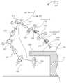
図2を参照すると、一実施形態による、ロボットアームを有する外科用ロボットシステムの概略図が示されている。外科用ロボットシステム100は、下で説明するように、遠隔運動中心を固定したままにすることができる。外科用ロボットシステム100は、外科用ロボットプラットフォーム111上に装着された外科用ロボットアーム112を含むことができる。外科用ロボットプラットフォーム111は、手術中に患者102が横たわる手術台202及び地面の上に手術台202を保持する支持カラム又は脚部などの、いくつかの構成要素を含むことができる。同様に、外科用ロボットアーム112は、いくつかのジョイント又はリンクを有するロボットアーム204、及びジョイント又はリンクを互いに対して駆動することができるいくつかのアクチュエータ、例えばモータなどの、いくつかの構成要素を含むことができる。図2では、回転ジョイントがシリンダとして表されており、リンクは、シリンダを接続する線を有するように示されている。一実施形態では、ロボットアーム204は、手術台202の下に装着されて、収容構成(図示せず)で手術台202の下に収容することができる。ロボットアーム204は、収容構成から、示されるように、外科用ツール104が手術台202の上に位置付けられる能動構成へと、アクチュエータによって移動させることができる。2, a schematic diagram of a surgical robotic system with a robotic arm is shown, according to one embodiment. The surgical
外科用ロボットアーム112は、手術中に外科用ツール104を位置付けて制御することが可能な、多軸ロボットマニピュレータとすることができる。外科用ロボットアーム112の軸は、ロボットアーム204の全体的な幾何学形状を制御する自由度を表す。例えば、いくつかのリンクされたジョイントを有する設定アーム250は、手術台202に、例えば手術台202の下側に取り付けることができる。設定アーム250は、1又は2以上の自由度を有する台アダプタジョイント208によって手術台202に結合され得る。台アダプタジョイント208は、設定アーム250がいくつかの軸の周りで手術台202に対して移動することを可能にする、サブジョイントの任意の組み合わせ、例えば一対の回転ジョイントとすることができる。同様に、設定アーム250は、アダプタジョイント209を含むことができ、これは、台アダプタジョイント208と組み合わせたときに、手術台202に対する設定アーム250の1又は2以上の自由度を提供する。設定アーム250は、相互接続したアームに1又は2以上の自由度を付与する、1つ又は2つ以上の追加のジョイント、例えば、ジョイント206及び/又はジョイント210などのロールジョイント、又はジョイント207及び/又はジョイント211などのピッチジョイントを含むことができる。各ジョイントは、それぞれの軸の周りの回転を可能にし得、したがって、対応する用語は、「ピッチ」及び「ロール」である。設定アーム250のリンクされたアーム、及び手術台202と遠隔運動中心機構との間のロボットアーム204の任意の他のリンクは、所定の自由度で、空間内に遠隔運動中心機構を位置付けることができる。例えば、手術台202とロボットアーム204のロールジョイント212との間のリンクは、組み合わせて、空間のロールジョイント212の近位端を位置付ける、5自由度のアーム、例えば設定アーム250を形成することができる。The surgical
遠隔運動中心機構は、いくつかのジョイント又はリンクを含むことができる。一実施形態では、ロールジョイント212は、遠隔運動中心機構の第1のジョイントである。遠隔運動中心機構は、球状アーム252とも称することができ、球状アーム252の近位端は、設定アーム250の遠位端に接続することができる。同様に、球状アーム252の遠位端は、ツールドライブ214に接続することができる。遠隔運動中心機構は、手術中に遠隔運動中心216で外科用ツール104(又は外科用ツール104を保持するツールドライブ214)を保持及び配向するように構成されている。したがって、球状アーム252は、本質的に、外科用ツール104がその周りを枢動する遠隔運動中心216を画定する、ロボットアーム204の一部分である。The remote center of motion mechanism may include several joints or links. In one embodiment, the roll joint 212 is the first joint of the remote center of motion mechanism. The remote center of motion mechanism may also be referred to as a
ロールジョイント212及びツールドライブ214に加えて、遠隔運動中心機構は、ロールジョイント212をツールドライブ214に接続するプリズムリンク218を含む。より具体的には、ロールジョイント212の遠位端は、プリズムリンク218の近位端に接続することができる。第1のピッチジョイント220はまた、ロールジョイント212及びプリズムリンク218に結合され得る。例えば、第1のピッチジョイント220は、ロールジョイント212とプリズムリンク218との間の中間にあり得る。一実施形態では、第1のモータは、ロールジョイント212及びプリズムリンク218に接続されて、第1のピッチジョイント220に1又は2以上の自由度を提供する。例えば、プリズムリンク218は、第1のピッチジョイント220の周りでロールジョイント212に対して枢動することができる。同様に、プリズムリンク218の遠位端は、第2のピッチジョイント224においてツールドライブ214に接続することができる。第2のモータは、プリズムリンク218及びツールドライブ214に接続して、第2のピッチジョイント224に1又は2以上の自由度を提供することができる。例えば、ツールドライブ214は、第2のピッチジョイント224の周りでプリズムリンク218に対して枢動することができる。In addition to the roll joint 212 and the
遠隔運動中心機構を形成するリンクの1つ又は2つ以上は、可変長を有する。例えば、遠隔運動中心機構のリンクは、プリズムジョイント230によって互いに接続されたサブリンクを含むことができる。プリズムジョイント230は、サブリンク間の摺動運動を可能にし、したがって、サブリンクからなるリンクの全体的な長さを増減させることができる。一実施形態では、ロボットアーム204のプリズムリンク218は、ロールジョイント212とツールドライブ214との間にプリズムジョイント230を含む。例えば、下で説明するように、プリズムリンク218は、プリズムジョイント230によって結合されたいくつかのプリズムサブリンクを有することができ、プリズムサブリンクに接続されたモータは、サブリンクを互いに対して摺動させて、プリズムリンク218の長さ、及び結果的に、ツールドライブ214とロールジョイント212との間の距離を増減させることができる。One or more of the links forming the remote motion center mechanism have a variable length. For example, the links of the remote motion center mechanism can include sub-links connected to each other by
プリズムジョイント230は、外科用ロボットアーム112の他の構成要素に組み込まれ得る。例えば、ツールドライブ214は、外科用ツール104がツールドライブ214と第2のピッチジョイント224との間で取り付け点に対して線形に移動することを可能にするように、プリズムジョイント230を含み得る。ツールドライブ214のプリズムジョイント230は、患者102に対して前進又は後退させることができる、入れ子体とすることができる。摺動移動は、外科用ツール104を患者102に挿入すること、及びそこから後退させることを可能にすることができる。更に、外科用ロボットアーム112のアクチュエータの全ては、外科用ツール104を遠隔運動中心216に維持するように協調して制御され得る。The prism joint 230 may be incorporated into other components of the surgical
図3を参照すると、一実施形態によるロボットアームの斜視図が示されている。ロボットアーム204は、球状アーム252を含むことができる。ロボットアーム204は、ロール軸302に沿って延在するロールジョイント212を含むことができる。ロール軸302は、その周りでロールジョイント212が回転し得る幾何学的基準特徴である。例えば、ロールジョイント212の近位端は、回転ジョイント、例えばジョイント211において設定アーム250に取り付けられ得る。モータは、回転ジョイントでのロールジョイント212の回転を駆動して、ロールジョイント212の遠位端をロール軸302の周りで回転させることができる。したがって、ロールジョイント212は、ロボットアーム204に少なくとも1の自由度を、例えばロール軸302の周りの回転を提供し得る。Referring to FIG. 3, a perspective view of a robotic arm according to one embodiment is shown. The
ロール軸302は、ロールジョイント212が第1のピッチジョイント220においてプリズムリンク218に接続する、ロールジョイント212の遠位端を通って延在することができる。第1のピッチジョイント220は、第1のピッチ軸304の周りで回転することができる。より具体的には、ロールジョイント212の遠位端は、第1のピッチジョイント220によってプリズムリンク218の近位端に接続することができ、対応するアクチュエータは、第1のピッチジョイント220でのロールジョイント212に対するプリズムリンク218の回転を駆動することができる。例えば、モータは、第1のピッチジョイント220においてロールジョイント212及びプリズムリンク218に接続することができ、モータの作動は、プリズムリンク218を第1のピッチ軸304の周りでロールジョイント212に対して回転させることができる。したがって、第1のピッチジョイント220は、ロボットアーム204に少なくとも1の自由度を、例えば第1のピッチ軸304の周りの回転を提供することができる。The
プリズムリンク218は、線形軸306に沿って、第1のピッチジョイント220の近位端から第2のピッチジョイント224の遠位端へと延在することができる。第2のピッチジョイント224は、プリズムリンク218をツールドライブ214に接続することができる。第2のピッチジョイント224は、第2のピッチ軸308の周りで回転することができる。より具体的には、対応するアクチュエータは、第2のピッチジョイント224でのツールドライブ214に対するプリズムリンク218の回転を駆動することができる。例えば、モータは、第2のピッチジョイント224においてツールドライブ214及びプリズムリンク218に接続することができ、モータの作動は、プリズムリンク218を第2のピッチ軸308の周りでツールドライブ214に対して回転させることができる。したがって、第2のピッチジョイント224は、ロボットアーム204に少なくとも1の自由度を、例えば第2のピッチ軸308の周りの回転を提供することができる。The prism link 218 can extend along the
第1のピッチジョイント220及び第2のピッチジョイント224に加えて、プリズムリンク218は、ロボットアーム204に追加の自由度を付与するプリズムジョイント230と関連付けられ得る。プリズムジョイント230は、プリズムリンク218が、線形軸306に沿って延在及び後退することを可能にする。一実施形態では、プリズムリンク218は、プリズムリンク218の近位端を有する第1のプリズムサブリンク310を含む。第1のプリズムサブリンク310の近位端は、第1のピッチジョイント220によってロールジョイント212に接続することができる。同様に、プリズムリンク218は、プリズムリンク218の遠位端を有する第2のプリズムサブリンク312を含むことができる。第2のプリズムサブリンク312の遠位端は、第2のピッチジョイント224によってツールドライブ214に接続することができる。第1のプリズムサブリンク310は、プリズムジョイント230によって第2のプリズムサブリンク312に直接的又は間接的に接続することができる。In addition to the first pitch joint 220 and the second pitch joint 224, the
プリズムリンク218のプリズムジョイント230は、1つ又は2つ以上の段を含むことができる。例えば、第1のプリズムサブリンク310は、細長いチューブ状構造を有することができ、第1のプリズムサブリンク310の管状壁の内面は、第2のプリズムサブリンク312の外面に対して摺動し得る。プリズムリンク218の入力サブリンク及び出力サブリンクが直接接続されたとき、例えばプリズムリンク218が2つのセグメントだけを有するとき、プリズムジョイント230は、単段プリズムジョイント230であり得る。The
一実施形態では、プリズムリンク218は、2つを超えるセグメントを有する入れ子構造である。より具体的には、プリズムリンク218は、第1のプリズムサブリンク310と、第2のプリズムサブリンク312と、少なくとも1つの追加のプリズムサブリンクと、を含むことができる。追加のプリズムサブリンクリンクは、プリズムジョイント230によって第1のプリズムサブリンク310及び第2のプリズムサブリンク312に接続された中間プリズムサブリンク314であり得る。より具体的には、プリズムジョイント230は、第1のプリズムサブリンク310と中間プリズムサブリンク314との間の摺動接点と、中間プリズムサブリンク314と第2のプリズムサブリンク312との間の摺動接点と、を含むことができる。プリズムリンク218の入力サブリンク及び出力サブリンクが直接接続されないとき、例えばプリズムリンク218が第1のプリズムサブリンク310と第2のプリズムサブリンク312との間に少なくとも1つの中間プリズムサブリンクを有するとき、プリズムジョイント230は、多段プリズムジョイント230であり得る。In one embodiment, the
プリズムジョイント230が単段プリズムジョイントであるか多段プリズムジョイントであるかにかかわらず、第1のピッチジョイント220と第2のピッチジョイント224との間の距離は、第2のプリズムサブリンク312を第1のプリズムサブリンク310から離れて駆動することによって増加され得、距離は、第2のプリズムサブリンク312を第1のプリズムサブリンク310に向かって駆動することによって減少され得る。対応するアクチュエータは、プリズムサブリンクの、例えば第1のプリズムサブリンク310及び第2のプリズムサブリンク312の線形軸306に沿った互いに対する並進を駆動することができる。例えば、モータは、直接的に又は中間プリズムサブリンク314を通して、第1のプリズムサブリンク310及び第2のプリズムサブリンク312に接続して、第1のプリズムサブリンク310を線形軸306に沿って第2のプリズムサブリンク312に対して摺動させることができる。Regardless of whether the prism joint 230 is a single-stage prism joint or a multi-stage prism joint, the distance between the first pitch joint 220 and the second pitch joint 224 can be increased by driving the
線形軸306に沿ったプリズムリンク218の延在及び後退は、ロボットアーム204の全体的なサイズを変化させることができる。例えば、第2のプリズムサブリンク312は、第2のピッチジョイント224が第1のプリズムサブリンク310の遠位端に隣接するまで、線形軸306に沿って第1のプリズムサブリンク310に向かって駆動して、プリズムリンク218の長さを減少させることができる。この状態では、プリズムリンク218は、最小又はほぼ最小の長さである。したがって、ロボットアーム204は、第2のプリズムサブリンク312が後退したときの状態において、第2のプリズムサブリンク312が延在したときの状態よりもコンパクトにすることができる。一実施形態では、ロボットアーム204は、プリズムリンク218が最小又はほぼ最小の長さの状態であるときに、手術台202の下に収容される。したがって、可変長の拡張可能なプリズムリンク218は、ロボットアーム204にコンパクトさを付与し、かつロボットアーム204を、使用していないときに、手術台202の上又は側面のスペースを取ることなく、収容することを可能にする。The extension and retraction of the
プリズムリンク218の最大長は、より多くのリンクセグメントを使用することによって増加され得ることが理解されるであろう。例えば、プリズムジョイント230のいくつかの段を増加させることは、線形軸306に沿ったプリズムリンク218の運動範囲の比例的な増加を有することができる。しかしながら、ステージの数を増加させることは、システムのサイズ、重量、及び複雑さを増加させ得る。ある設計は、外科手術を行うために必要なアームの届く範囲と、手術台の下にコンパクト化されたリンケージを収容する能力とをバランスさせ得ることが示されている。一実施形態では、このバランスは、図3に示されるような2つの段(プリズムリンク218は、2つの摺動接触点で接続される3つのサブリンクを含む)を有するプリズムジョイント230によって達成される。It will be appreciated that the maximum length of the
プリズムリンク218は、外科用ツール104を保持し、移動させることができるツールドライブ214を支持することができる。ツールドライブ214はまた、手術中の外科用ツール104の移動を案内することもできる。一実施形態では、ツールドライブ214は、外科用ツール104(図3に示さず)及び/又はツールガイド350を支持するように構成されている。外科用ツール104及び/又はツールガイド350は、挿入軸352に沿って延在することができる。外科用ツール104及び/又はツールガイド350は、挿入軸352に沿って遠隔運動中心216を通して患者102に挿入するように構成することができる。ツールガイド350の構成要素、例えばガイドチューブ354は、外科用ツール104の特徴、例えば外科用ツール104の遠位シャフトを受容し、案内することができる。例えば、ガイドチューブ354は、挿入軸352と同軸である管腔を有するトロカールを含むことができ、したがって、シャフトが管腔に挿入されるときに外科用ツール104のシャフトを受容することができる。ガイドチューブ354は、ツール特徴を患者102のアクセス点の中へ、又はそれを通して案内することができる。したがって、挿入軸352、外科用ツール104のシャフト、及びガイドチューブ354の管腔は、遠隔運動中心216を通って延在することができる。The prism link 218 can support a
一実施形態では、挿入軸352は、遠隔運動中心216においてロール軸302と交差する。挿入軸352とロール軸302との間の交差は、遠隔運動中心機構の他の基準幾何学形状の相対配向によって容易になる。例えば、第1のピッチ軸304は、第2のピッチ軸308と平行であり得る。したがって、第1のピッチジョイント220及び/又は第2のピッチジョイント224の回転は、平面の外へ軸を移動させることなく、ロール軸302に沿った第1のピッチ軸304と挿入軸352との間の距離を変化させることができる。すなわち、平行なピッチ軸304、308は、軸302、352が共平面である同じ平面に対して直角であり、したがって、軸304、308の周りのリンクの回転は、同じ平面内の軸302、352の相対移動を生じさせる。したがって、ロール軸302及び挿入軸352は、遠隔運動中心機構の移動中に同一平面上のままである。同様に、プリズムジョイント230は、第1のピッチ軸304及び第2のピッチ軸308に対して直角であり得る線形軸306に沿って摺動することができる。線形軸306とピッチ軸との間の直交性は、プリズムリンク218の長さが収容構成から能動構成へと変化したときであっても、挿入軸352をロール軸302と同じ平面内のままにすることを可能にする。In one embodiment, the
ロボットアーム構成要素と基準幾何学形状との間の相対位置は、ロール軸302、線形軸306及び挿入軸352によって基準三角形が形成される構造を作ることができる。ロール軸302及び挿入軸352は、三角形の脚部を形成し、線形軸306は、第1のピッチ軸304と第2のピッチ軸308との間で挿入軸352へと延在して、三角形の斜辺を形成する。斜辺の長さは、プリズムジョイント230においてプリズムリンク218のサブリンクを移動させることによって、例えば、第1のピッチジョイント220及び第2のピッチジョイント224を通って延在している線形軸306に沿ってプリズムジョイント230を摺動させることによって変化させることができる。同様に、第1のピッチジョイント220及び第2のピッチジョイント224においてリンクを移動させることによって挿入軸352とロール軸302との間の角度が変化したときに、脚部の長さが変化する。脚部及び三角形の斜辺は、ロール軸302の周りで回転することができる平面内に存在する。三角形は、挿入軸352がロール軸302と交差する頂点を有する。一実施形態では、ロボットアーム204のリンクは、遠隔運動中心216に頂点を位置付けるために、第1のピッチジョイント220、プリズムジョイント230、及び第2のピッチジョイント224でのそれぞれのモータの移動によって制御される。The relative positions between the robot arm components and the reference geometry can be constructed such that a reference triangle is formed by the
ツールドライブ214は、外科用ツール104(図7A~図8B)を保持するためにキャリッジ356を含むことができる。下で説明するように、キャリッジ356は、ツールガイド350に対して挿入軸352の方向に移動可能である。より具体的には、ツールドライブ214は、キャリッジ356をツールガイド350に接続するそれぞれのプリズムジョイントを有することができ、プリズムジョイントは、キャリッジ356が、挿入軸352に沿って、ガイドチューブ354に向かって、又はそこから離れて移動することを可能にすることができる。したがって、キャリッジ356上に装着される外科用ツール104の遠位端又はシャフトは、キャリッジ356の移動と平行に移動することができる。ガイドチューブ354の位置、例えばガイドチューブ354の管腔の位置が、リンケージジョイントのそれぞれの運動軸の周りの/に沿ったリンケージジョイントのソフトウェア制御の移動に基づいて、遠隔運動中心216に維持されている間、外科用ツール104の遠位端及び/又はシャフトを、ガイドチューブ354の管腔を通して挿入又は後退させることができる。外科用ツール104の遠位端及び/又はシャフトは、遠隔運動中心216に並置される患者102のアクセス点を通って移動させることができる。したがって、ツール特徴は、遠隔運動中心216の周りで枢動することができる。The
図4を参照すると、一実施形態による、ホーム構成にあるロボットアームの側面図が示されている。ロボットアーム204は、リンケージジョイントでの移動を制御することによって、多数の構成又は状態の間で連続的に移動することができる。一実施形態では、リンケージの移動は、遠隔運動中心216が空間の固定点に維持され、ガイドチューブ354が遠隔運動中心の周りで枢動するように制御することができる。よって、ガイドチューブ354の遠位端、例えばロール軸302の下、及び/又は外科用ツール104の遠位端は、ガイドチューブ354が遠隔運動中心216の周りで枢動するときに、円錐作業空間402を通してスイープすることができることが理解されるであろう。円錐作業空間402のスイープされる作業角度404は、下で説明するように、可変長リンクの長さに依存することができる。例えば、作業角度404が最大になる最適リンク長が存在し得る。同様に、円錐作業空間402の半径は、挿入軸352に沿ったキャリッジ356の位置に依存することができる。例えば、外科用ツール104の遠位端を挿入軸352に沿って遠位方向に駆動することで、遠隔運動中心216の下の円錐作業空間402の半径を増加させることができる。4, a side view of the robot arm in a home configuration is shown, according to one embodiment. The
ロボットアーム204は、いくつかのホーム構成406を有することができる。ホーム構成は、ロール軸302が挿入軸352に対して直角であるリンケージ構成として画定され得る。ホーム構成406では、ロール軸302は、遠隔運動中心216において挿入軸352と交差することができる。遠隔運動中心機構を画定する基準三角形は、ホーム構成の直角三角形とすることができる。各ホーム構成に対応する基準三角形は、プリズムリンク218の長さに応じて、異なる長さの斜辺を有することができ、同様に、各ホーム構成406の基準三角形は、第1のピッチジョイント220と遠隔運動中心216との間のそれぞれのホーム距離408を有することができる(ホーム距離408は、基準三角形のベース脚部の長さである)。ロボットアーム204のホーム構成406ごとに、ロボットアーム204の第1のピッチジョイント220、プリズムジョイント230、及び第2のピッチジョイント224は、遠隔運動中心216に外科用ツール104及び/又はツールガイド350を維持しながら、作業角度404を通して挿入軸352をスイープするように移動可能である。The
作業角度404は、ロボットアーム112がツールガイド350を遠隔運動中心216で維持することができる傾斜ゾーンを表す。この範囲外では、遠隔運動中心機構の1つ又は2つ以上のジョイントは、運動を続けることが不可能であり得、したがって、遠隔運動中心216と一致するようにツールガイド350を更に調整することが不可能であり得る。例えば、プリズムジョイント230及び/又は第2のピッチジョイント224は、第1の方向の運動範囲の端部(図5)、又は反対方向の運動範囲の端部(図6)にあり得る。したがって、いずれの場合でも、第1のピッチジョイント220での運動が続けられる場合、ツールガイド350上の位置は、第1のピッチジョイント220の周りで枢動して、遠隔運動中心216から離れて移動する。The working
図5を参照すると、一実施形態による、前方にピッチした構成のロボットアームの側面図が示されている。挿入軸352は、枢動ガイドチューブ354を遠隔運動中心216の周りで枢動するように前方にピッチさせることができる。ツールガイド350のピッチ運動は、第1のピッチジョイント220、第2のピッチジョイント224、又はプリズムジョイント230のうちの1つ又は2つ以上での同時の運動を作動させることによって生じされ得る。より具体的には、プリズムリンク218は、伸ばすことができ、同時に挿入軸352とロール軸302との間の角度502を(時計回り方向に)増加させて、遠隔運動中心216でのガイドチューブ354上の同じ位置を維持することができる。ツールガイド350が前方にピッチするとき、運動範囲が設定される。運動範囲は、ロール軸302と遠隔運動中心216を通って延在している挿入軸352との間の角度502内であり得る。ロール軸302に対して直角に延在している垂直軸(図示せず)は、基準幾何学形状として使用することができる。垂直軸は、ホーム構成406において挿入軸352と共線とすることができる。前方ピッチ構成では、前方作業サブ角度を、垂直軸と挿入軸352との間に形成することができる。前方作業サブ角度は、円錐作業空間402の一部分を画定することができる。より具体的には、前方作業サブ角度は、垂直軸基準幾何学形状を含み、かつページに対して直角である平面の第1の側に、円錐作業空間402の一部分を画定することができる。5, a side view of the robot arm in a pitched forward configuration is shown, according to one embodiment. The
図6を参照すると、一実施形態による、後方ピッチ構成のロボットアームの側面図が示されている。挿入軸352は、遠隔運動中心216の周りでガイドチューブ354を枢動するために後方にピッチさせることができる。より具体的には、プリズムリンク218は、縮めることができ、同時に挿入軸352とロール軸302との間の角度602を角度502から減少させて、遠隔運動中心216でのガイドチューブ354上の同じ位置を維持することができる。外科用ツール104及び/又はツールガイド350が後方にピッチするとき、図5の角度502と図6の角度602との間の差が、円錐作業空間402の作業角度404を画定することができる。後方ピッチ構成では、後方作業サブ角度を、垂直軸と挿入軸352との間に形成することができる。後方作業サブ角度は、前方作業サブ角度によって画定される作業空間の一部分の反対側の円錐作業空間402の一部分を画定することができる。6, a side view of the robot arm in a pitch-back configuration is shown, according to one embodiment. The
ロボットアーム204のホーム構成406ごとに、挿入軸352によってスイープされる作業角度404は、ホーム構成406のそれぞれのホーム距離408に基づき得る。所与のホーム距離408の場合、挿入軸352は、ロール軸302に対して特定の運動範囲を有する。運動範囲は、図5の前方作業サブ角度及び図6の後方作業サブ角度を通したピッチ運動を含むことができる。あるホーム構成406の場合、前方作業サブ角度及び後方作業サブ角度は、等しい。そのホーム構成の場合、円錐作業空間402の対称軸は、垂直軸基準幾何学形状と同軸である。作業角度404は、対称のホーム構成において最大になり得る。他のホーム構成の場合、前方作業サブ角度及び後方作業サブ角度は、等しくない。そうしたホーム構成406の場合、円錐作業空間402の対称軸は、垂直軸に対して傾斜している。例えば、下で説明するように、ホーム構成406のホーム距離408が増加するにつれて、前方作業サブ角度が減少し、後方作業サブ角度が増加する。対照的に、ホーム構成406のホーム距離408が減少するにつれて、前方作業サブ角度が増加し、後方作業サブ角度が減少する。換言すれば、前方作業サブ角度は、ホーム距離408に反比例し得、後方作業サブ角度は、所与のホーム構成406の場合、ホーム距離408に比例し得る。For each
設計されているホーム距離に基づく作業角度404のいくつかの例をここで一例として説明するが、限定するものではない。対称の前方及び後方作業サブ角度を有するホーム構成は、425mmのホーム距離408を有することができる。すなわち、ホーム構成の場合、挿入軸352がロール軸302に対して直角であるとき、遠隔運動中心216は、第1のピッチジョイント220から425mm離間され得る。ホーム構成406では、ロール軸302は、挿入軸352及び垂直軸基準幾何学形状に対して直角であり、かつ遠隔運動中心216において両方の軸と交差する。ツールドライブ214が、ツールガイド350上の同じ位置を遠隔運動中心216に位置付けることができる最大角度へと、すなわち対称ホーム構成406の場合の作業角度502へと前方にピッチされるとき、挿入軸352は、垂直軸基準幾何学形状から70度離れ得る。同様に、ツールドライブ214が、ツールガイド350上の同じ位置を遠隔運動中心216に位置付けることができる最大角度へと、すなわちホーム構成406の場合の図6の後方作業サブ角度へと後方にピッチされるとき、挿入軸352は、垂直軸基準幾何学形状から-70度離れ得る。Some examples of the
非対称前方及び後方作業サブ角度を有する代替のホーム構成406は、525mmのホーム距離408を有することができる。すなわち、非対称ホーム構成406の場合、挿入軸352がロール軸302に対して直角であるとき、遠隔運動中心216は、第1のピッチジョイント220から525mm離間され得る。非対称ホーム構成406では、ロール軸302は、挿入軸352及び垂直軸基準幾何学形状に対して直角であり、かつ遠隔運動中心216において両方の軸と交差する。ツールドライブ214が、非対称ホーム構成406の場合の角度502へと前方にピッチされるとき、挿入軸352は、垂直軸基準幾何学形状から30°(前方方向における全運動範囲未満)離れ得る。対照的に、ツールドライブ214が、代替のホーム構成406の場合の角度602へと後方にピッチされるとき、挿入軸352は、垂直軸基準幾何学形状から-70度(後方方向における全運動範囲)離れ得る。The
別の非対称ホーム構成は、325mmの代替のホーム距離408を有する。すなわち、非対称ホーム構成406の場合、挿入軸352がロール軸302に対して直角であるとき、遠隔運動中心216は、第1のピッチジョイント220から325mm離間され得る。外科用ツール104及び/又はツールドライブ214が非対称ホーム構成406の場合の前方作業角度502へと前方にピッチされるとき、挿入軸352は、垂直軸基準幾何学形状から70度(前方方向における全運動範囲)離れ得る。対照的に、外科用ツール104及び/又はツールドライブ214が、非対称ホーム構成406の場合の後方作業角度602へと後方にピッチされるとき、挿入軸352は、垂直軸基準幾何学形状から-5度(後方方向における全運動範囲未満)離れ得る。Another asymmetric home configuration has an
上記の例は、入力ジョイントから遠隔運動中心216まで一定の距離を有するハードウェア拘束されたロボットアームとは対照的に、ソフトウェア制御のロボットアームが、ホーム距離408を変化させる能力を提供することを示す。更に、ホーム距離408を変化させることによって、外科用ツール104及び/又はツールガイド350の運動範囲を制御することができる。これは、運動範囲を、特定の動作状態に対して最適化することを可能にする。例えば、ホーム距離408を増加させ、それに応じて前方作業角度502を減少させることによって、外科用ツール104及び/又はツールドライブ214と患者102又はベッド横の操作者106との間に追加のクリアランスが提供され得る。追加の患者クリアランスによって、ベッド横の操作者106が、ロボットアームにぶつかるリスクを少なくしながら、患者102のアクセス点の周囲の空間内で作業することを可能にすることができる。同様に、ホーム距離408を減少させることによって、外科用ロボットアーム112を全体的により小さくして、隣接するロボットアームとの衝突を回避することができる。円錐作業空間402を最大にすることが必要である場合、例えば、外科手術によって患者102の体内での最大運動範囲が必要とされる場合、ホーム距離408を、対称ホーム構成及び対応する最大作業サブ角度を達成するように変化させることができる。したがって、ハードウェア拘束されたロボットアームと比較して、本明細書で説明される外科用ロボットアーム112は、特定の外科用シナリオのニーズに適合され得る。The above example shows that, in contrast to a hardware-constrained robotic arm that has a fixed distance from the input joint to the remote center of
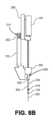
図7A~図7Bを参照すると、一実施形態による、ツールドライブ上に装着された外科用ツールの側面図が示されている。ツールドライブ214は、挿入軸352に沿って、遠位方向(ガイドチューブ354に向かう)及び近位方向(ガイドチューブ354から離れる)にキャリッジ356を移動させることができる。線形運動は、外科用ツール104を、挿入軸352に沿った異なる位置において、完全後退状態から完全挿入状態へと移動させることができる。7A-7B, a side view of a surgical tool mounted on a tool drive is shown, according to one embodiment. The
図7Aは、完全後退状態のキャリッジ356及び外科用ツール104を示す。一実施形態では、ツールドライブ214は、ツールガイド350に固定されたガイドベース702を含む。例えば、ツールガイド350は、ガイドベース702上に装着することができる。転じて、ガイドチューブ354は、ガイドベース702に対する空間内の一貫した位置を有することができる。他方では、キャリッジ356は、ベース702を案内するように移動可能に結合され得る。例えば、ガイドベース702は、モータ駆動ねじなどの線形アクチュエータによって挿入軸352と平行に駆動される、段などの直動軸受を含み得る。キャリッジ356は、ガイドベース702に対して遠位方向及び近位方向に移動させるように、直動軸受に直接装着することができる。外科用ツール104は、外科用ツール104のシャフト704が挿入軸352に沿って遠位方向に延在するように、キャリッジ356上に装着することができる。完全後退状態では、シャフト704は、キャリッジ356とツールガイド350との間の垂直空間に保持され得る。7A shows the
図7Bは、完全延在状態のキャリッジ356及び外科用ツール104を示す。キャリッジ356及び外科用ツール104は、挿入軸352に沿ってガイドベース702に対して遠位に駆動することができる。キャリッジ356が前方に駆動されると、外科用ツール104のシャフト704は、ガイドチューブ354の管腔に進入することができる。キャリッジ356の継続的な線形運動は、シャフト704の遠位端が現れるまで、ガイドチューブ354を通してシャフト704を挿入することができる。手術中に、シャフト704の遠位端は、ガイドチューブ354を外科用アクセス点内に挿入するときに患者102の体内で外科手術を行うために使用され得るカメラ、把持具、又は別のエンドエフェクタを含むことができる。7B shows the
図8A~図8Bを参照すると、一実施形態による、入れ子ツールドライブ上に装着された外科用ツールの側面図が示されている。一実施形態では、ツールドライブ214は、多段のプリズムジョイントを含むことができる。より具体的には、プリズムリンク218のように、ツールドライブ214は、入れ子式でキャリッジ356の移動を生じさせる構成要素を組み込むことができる。8A-8B, a side view of a surgical tool mounted on a telescoping tool drive is shown, according to one embodiment. In one embodiment, the tool drive 214 can include a multi-stage prismatic joint. More specifically, like the
図8Aは、完全後退状態のキャリッジ356及び外科用ツール104を示す。一実施形態では、ガイドベース702は、ツールガイド350に固定される。他方では、キャリッジ356は、ベース702を案内するように移動可能に結合され得る。1つ又は2つ以上のアイドラリンク802は、ガイドベース702及びキャリッジ356の両方に接続することができ、アイドラリンク802は、ガイドベース702及びキャリッジ356の一方又は両方に対して同時に移動させることができる。ツールドライブ214のプリズムジョイントは、キャリッジ356及びツールベース702のうちの1つ又は2つ以上をアイドラリンク802に対して遠位方向及び近位方向に移動させるための機構を含むことができる。例えば、第1の線形軸受は、ツールベース702をアイドラリンク802に接続することができ、第1の線形アクチュエータは、軸受によって画定された運動の方向にアイドラリンク802を駆動することができる。同様に、第2の線形軸受は、アイドラリンク802をキャリッジ356に接続することができ、第2の線形アクチュエータ(又はベルトなどの伝達要素)は、軸受によって画定された運動の方向にキャリッジ356を駆動することができる。したがって、キャリッジ356は、入れ子式でツールベース702に対して移動させることができる。一実施形態では、第2のピッチジョイント224は、ガイドベース702をアイドラリンク802に沿った第2のピッチジョイント224における接続部に対して前方及び後方に駆動することができるように、アイドラリンク802に接続することができる。8A shows the
図8Bは、完全延在状態のキャリッジ356及び外科用ツール104を示す。キャリッジ356及び外科用ツール104は、挿入軸352に沿ってガイドベース702に対して遠位に駆動することができる。例えば、アイドラリンク802は、ガイドベース702に対して遠位に駆動することができ、及び/又はキャリッジ356は、アイドラリンク802に対して遠位に駆動することができる。キャリッジ356が前方に駆動されると、外科用ツール104のシャフト704は、ガイドチューブ354の管腔に進入することができる。キャリッジ356の継続的な線形運動は、外科手術を行うためにシャフト704の遠位端が患者102の体内に現れるまで、ガイドチューブ354を通してシャフト704を挿入することができる。一実施形態では、図8A~図8Bに示されるツールドライブ214の入れ子作用は、ツールドライブ214の全体的なエンベロープを最小にすることを可能にする。より具体的には、追加のプリズムジョイント段の使用によって、ツールドライブ214がコンパクト化された状態でより小さい空間内に適合することを可能にすることができる。したがって、入れ子プリズムジョイント230を有するツールドライブ214は、手術台202の下に収容することができる。8B shows the
一実施形態では、ツールドライブ214の運動範囲は、ツールドライブ214と患者102との間のクリアランスを調整することによって増加させることができる。より具体的には、運動範囲は、ツールドライブ214が挿入軸352に沿って第2のピッチジョイント224に結合される位置を移動させること、又は入れ子体をツールガイド350に動作可能に組み込んで挿入軸352に沿って入れ子にすること、のうちの1つ又は2つ以上によって増加させることができる。これらの特徴は、上で説明した実施形態のうちのいずれかに組み込むことができるが、特徴は、図8A~図8Bにのみ例示されていることが理解されるであろう。In one embodiment, the range of motion of the tool drive 214 can be increased by adjusting the clearance between the
図8Aを再度参照すると、ツールドライブ214が第2のピッチジョイント224(図示せず)に結合される結合位置は、挿入軸352に沿って動作可能に移動可能である。一実施形態では、結合位置810の装着点は、ツールドライブ段に沿って、例えばツールガイドベース702上を移動可能であり得る。例えば、ツールガイドベース702は、近位結合位置810、及び中間結合位置812、遠位結合位置814など、のうちの1つ又は2つ以上においてツールガイド350に接続することができる。接続部は、例えば、ツールガイド350に個々に接続する結合位置810、812、及び814に位置するそれぞれの結合部を通した、様々な離散した位置とすることができる。代替的に、ツールガイドベース702及びツールガイド350は、線形スライドの移動可能部分上に装着され得、したがって、スライドを作動させることによって互いに対して移動させることができる。スライドが作動すると、ツールガイド350が点810、812、814などへ移動することができ、したがって、ツールガイドベース702に対する位置を変化させることができる。したがって、ツールガイド350は、ツールガイドベース702に対する離散した位置に対してラッチ係合解除及びラッチ係合して、又はツールガイドベース702に対して連続的に移動させて、ツールドライブ214と患者102との間の距離を変化させることができる。例えば、ツールガイド350が位置814においてツールガイドベース702に取り付けられたとき、ツールドライブは、患者102からより遠くにある。ツールガイド350の装着点をツールドライブ段に沿って移動可能にすることによって、運動範囲502を増加させることができる。8A, the coupling location where the
図8Bを再度参照すると、ツールガイド350は、挿入軸352に沿って動作可能に入れ子である、入れ子体820を含む。入れ子体820は、一例として挿入軸352に沿って共線的にネストされる、近位ガイドチューブ822及び遠位ガイドチューブ824を含むことができる。一実施形態では、遠位ガイドチューブ824は、近位ガイドチューブ822内を前方又は後方に摺動して、ツールガイド350を入れ子にすることができる。入れ子体820を手動で又は自動的に作動させると、遠位ガイドチューブ824の遠位端の位置を変化させることができ、よって、患者102に対する遠隔運動中心216の位置を変化させることができる。これらの点が変化することで、運動範囲502が変化し得る。例えば、ガイドチューブは、ツールガイドベース702と患者102との間のクリアランスを増加させるように延在させることができる。したがって、運動範囲502を増加させることができる。8B, the
図9を参照すると、一実施形態による、遠隔運動中心を固定したままにするようにロボットアームを制御する方法のフローチャートが示されている。ロボットアーム204は、第1の構成に位置付けること、又はそれへと移動させることができる。第1の構成では、ロールジョイント212のロール軸302は、遠隔運動中心216においてツールドライブ214の挿入軸352と交差する。ロール軸302は、第1の構成において、挿入軸352から第1の角度離れる。例えば、第1の構成は、ホーム構成406とすることができ、第1の角度は、90度であり得る。代替的に、第1の構成は、ツールガイド350が垂直軸基準幾何学形状に対して傾斜される状態とすることができ、よって、第1の角度は、90度とは異なり得る。9, a flow chart of a method for controlling a robot arm to keep a remote center of motion fixed is shown, according to one embodiment. The
ロボットアーム204を第1の構成に移動させるために、リンケージの各ジョイントのモータを移動させることができる。例えば、第1のピッチジョイント220に位置付けられたステッパモータは、線形軸306とロール軸302との間の角度を変化させることができる。同様に、第2のピッチジョイント224に位置付けられたステッパモータは、線形軸306と挿入軸352との間の角度を変化させることができる。ステッパモータによって設定された角度は、プリズムリンク218のリンクに接続された線形アクチュエータによって駆動されるときに、プリズムリンク218の長さに対応することができる。プリズムリンク218のプリズムジョイント230を駆動する線形アクチュエータは、親ねじを含むことができる。例えば、入れ子プリズムリンク218の場合、中間サブリンク314は、親ねじの回転によって移動する、線形駆動軸受を含むことができる。他のサブリンク、例えば第1のサブリンク及び第2のサブリンクは、ベルト及びプーリ機構などの伝達機構を通して中間サブリンクに接続され得る。中間サブリンクが親ねじの回転によって移動すると、サブリンクを相互接続するベルトも移動して、リンクを押し得、及び/又は引き得る。したがって、サブリンクは、プリズムリンク218の全体的な長さの変化に同調して移動することができる。To move the
遠隔運動中心機構の構成要素の位置は、1つ又は2つ以上の位置センサによって検知することができる。例えば、ロールジョイント212、プリズムリンク218、及びツールドライブ214の移動及び/又は位置を検出するために、絶対位置センサのネットワークがロボットアーム204の全体にわたって分配され得る。一実施形態では、絶対センサは、ジョイントの位置を検出するために、ロボットアーム204の各ジョイントに、又はロボットアーム204(球状アームなど)の一部分の各ジョイントに位置付けられる。センサのネットワークからのフィードバックは、外科用ロボットシステム100(図10)のプロセッサによって受信して、ロボットアーム204の全体的な幾何学形状を決定するために処理することができる。プロセッサは、フィードバックを使用して、遠隔運動中心216を固定したままに保つジョイント構成を決定することができる。例えば、遠隔運動中心216は、ツールガイド350上の位置に固定したままにすることができる。プロセッサは、所望の幾何学形状を達成するようにアクチュエータを移動させる、駆動信号を生成することができる。例えば、プロセッサは、下で説明するように、ロボットアーム204の移動を第1の構成へと、又は後続の構成へと制御するための駆動信号を生成する。構成間の移動は、遠隔運動中心216を固定したままにしながら行うことができる。The position of the components of the remote motion center mechanism can be sensed by one or more position sensors. For example, a network of absolute position sensors can be distributed throughout the
動作902で、プロセッサは、挿入軸352に沿って遠隔運動中心216を通して患者102に挿入される外科用ツール104を移動させるように、ロボットアーム204を駆動することができる。例えば、プロセッサは、作業角度404を通して挿入軸352をスイープさせるように、ロボットアーム204を駆動することができる。挿入軸352は、外科用ツール104及び/又はツールガイド350が患者102に挿入されるとき、作業角度404を通してスイープさせることができる。外科用ツール104及び/又はツールガイド350は、挿入軸352に沿って遠隔運動中心216を通して患者102に挿入することができる。At
動作904で、プロセッサは、遠隔運動中心216を固定したままにするように、ロボットアーム204の移動、例えばロボットアーム204の設定アーム250及び球状アーム252のいくつかのジョイント又はリンクの移動を決定することができる。プロセッサは、位置センサのネットワークからのフィードバックを、ロボットアーム204の移動を制御するために使用される制御アルゴリズムへの入力として使用することができる。例えば、球状アームは、作業角度404を通して挿入軸352をスイープしている間、遠隔運動中心216を固定したままにするために、プロセッサの制御装置の下で移動又は案内されるように構成することができる。At
動作906で、プロセッサは、動作904で決定された、例えば球状アーム252のいくつかのジョイント又はリンクの移動を達成するように、ロボットアーム204を駆動することができる。ロボットアーム204の構成要素は、ロボットアーム204を第2の構成へと移動させるように再位置決めすることができる。ロボットアーム204の再位置付けは、プリズムサブリンクを互いに対して入れ子状に移動させることを含むことができる。より具体的には、プロセッサは、プリズムリンク218のいくつかのプリズムサブリンクが互いに対して摺動するように、プリズムリンク218の移動を制御することができる。プリズムジョイント230と関連付けられた線形アクチュエータは、第1のプリズムサブリンク310をプリズムジョイント230の線形軸306に沿って第2のプリズムサブリンク312に対して摺動するように作動させることができる。プリズムサブリンクを摺動させることは、線形軸306に沿って第1のプリズムサブリンク310を中間プリズムサブリンク314に対して第1の方向に摺動させることと、第2のプリズムサブリンク312を中間プリズムサブリンク314に対して第1の方向とは反対の第2の方向に摺動させることと、を含むことができる。より具体的には、サブリンクは、プリズムリンク218の全体的な長さを増加させるように、離れて摺動することができる。いずれの場合でも、プリズムサブリンクは、プリズムジョイント230によって互いに対して移動することができる。In
第2の構成では、ロール軸302は、挿入軸352から第2の角度離れる。第2の角度は、第1の角度とは異なり得る。第2の構成では、遠隔運動中心216は、第1の構成と同じ位置にあり得る。したがって、第1の構成から第2の構成への移動は、プロセッサによって、挿入軸352が作業角度404を通してスイープされる間、遠隔運動中心216を固定したままにするように制御される。In the second configuration, the
一実施形態では、ツールドライブ214のキャリッジ356は、挿入軸352の方向に移動する。より具体的には、キャリッジ356は、ツールガイド350に対して移動することができる。例えば、キャリッジ356は、挿入軸352に沿って遠位に駆動して、キャリッジ356上に装着される外科用ツール104のシャフト704を、ガイドチューブ354の管腔を通して患者102の中へ進ませることができる。In one embodiment, the
図10を参照すると、一実施形態による、外科用ロボットシステムの例示的なハードウェア構成要素のブロック図が示されている。例示的な外科用ロボットシステム100は、ユーザコンソール120、外科用ロボット1002、及び制御タワー130を含むことができる。外科用ロボットシステム100は、他の追加のハードウェア構成要素を含み得、したがって、図は、一例として提供されるものであり、このシステムアーキテクチャに限定するものではない。Referring to FIG. 10, a block diagram of exemplary hardware components of a surgical robotic system is shown, according to one embodiment. The exemplary surgical
上で説明したように、ユーザコンソール120は、コンソールコンピュータ110と、1つ又は2つ以上のUID126と、を含む。ユーザコンソール120は、コンソールアクチュエータ1004と、ディスプレイ128と、UIDトラッカ1006と、フットペダル124と、ネットワークインターフェース1108と、を含むことができる。ユーザコンソール120に着座しているユーザ又は外科医は、ユーザコンソール120の人間工学的な設定を手動で調整することができ、又は設定は、ユーザプロファイル又は選好に従って自動的に調整され得る。手動調整及び自動調整は、ユーザ入力又はコンソールコンピュータ110によって記憶された構成に基づいてコンソールアクチュエータ1004を駆動することを通して達成され得る。ユーザは、2つのマスタUID126及びフットペダル124を使用して外科用ロボット1002を制御することによって、ロボット支援手術を行い得る。UID126の位置及び方向は、UIDトラッカ1006によって連続的に追跡され、状態の変化は、コンソールコンピュータ110によってユーザ入力として記録されて、ネットワークインターフェース1008を介して制御タワー130に送られる。患者の解剖学的構造のリアルタイム外科用ビデオ、器具、及び関連するソフトウェアアプリケーションは、開放型又は没入型ディスプレイを含む、高解像度三次元ディスプレイ128上でユーザに提示することができる。As described above, the
他の既存の外科用ロボットシステムとは異なり、本明細書に開示されるユーザコンソール120は、単一の光ファイバケーブルを通じて制御タワー130に通信可能に結合され得る。ユーザコンソールはまた、改善された人間工学のための追加的な特徴も提供する。例えば、開放型及び没入型ディスプレイのどちらも、没入型ディスプレイと比較するためにだけ提供される。更に、改善された人間工学のために、外科医のための高度に調整可能な椅子及び電磁又は光トラッカを通して追跡されるマスタUIDがユーザコンソール120に含まれる。安全性を向上させるために、視線追跡、頭部追跡、及び/又は椅子の旋回追跡は、例えばユーザの視線が所定の期間を超えて開放型ディスプレイの手術部位に係合されていないときに遠隔操作を一時停止又はロックすることによって、偶発的なツールの運動を防止するために実行することができる。Unlike other existing surgical robotic systems, the
制御タワー130は、タッチスクリーンディスプレイを収容するモバイルポイントオブケアカート、外科医のロボット支援型の器具の操作を制御するコンピュータ、安全システム、グラフィカルユーザインターフェース(graphical user interface、GUI)、光源、並びにビデオ及びグラフィックコンピュータとすることができる。図10に示されるように、制御タワー130は、少なくとも視覚化コンピュータ、制御コンピュータ、及び補助コンピュータを含む中央コンピュータ1010と、チームディスプレイ及び看護師ディスプレイを含む様々なディスプレイ1012と、制御タワー130をユーザコンソール120及び外科用ロボット1002の両方に結合するネットワークインターフェース1014と、を含み得る。制御タワー130はまた、高度な光エンジン1016、電気外科用発電ユニット(electrosurgical generator unit、ESU)1018、並びに送気器及びCO2タンク1020などの、サードパーティデバイスも収容し得る。制御タワー130は、看護師ディスプレイタッチスクリーン、ソフトパワー及びeホールドボタン、ビデオ及び静止画像のためのユーザフェーシングUSB、並びに電子キャスタ制御インターフェースなどの、ユーザの利便性のための追加的な特徴を提供し得る。補助コンピュータはまた、リアルタイムLinuxを実行し得、ロギング/監視、及びクラウドベースのウェブサービスとの相互作用を提供する。 The
外科用ロボット1002は、標的の患者の解剖学的構造の上に位置付けることができる複数の一体型アーム112を有する、関節運動手術台111を含む。互換ツール104一式は、アーム112の遠位端に取り付けること、又はそこから取り外すことができ、外科医が、様々な外科処置を行うことを可能にする。外科用ロボット1002はまた、アーム112、台111、及びツール104の手動制御機器のための制御インターフェース1022も含み得る。制御インターフェースは、限定されないが遠隔制御装置、ボタン、パネル、及びタッチスクリーンなどの物品を含むことができる。また、システムによって処置を行うために、トロカール(スリーブ、シールカートリッジ、及び栓子)及びドレープなどの他の付属品も必要であり得る。いくつかの変形例では、複数のアーム112は、各側上に2つのアームを有する、手術台111の両側上に装着された前アームを含む。特定の外科処置の場合、台の一方の側上に装着されたアームは、台及び反対側に装着されたアームの下に伸ばして交差させることによって、台の反対側に位置付けることができ、台111の同じ側に位置付けられた合計で3つのアームをもたらす。外科用ロボット1002はまた、台のコンピュータ1024及びネットワークインターフェース1026を含むこともでき、これらは、制御タワー130と通信して外科用ロボット1002を配置することができる。The surgical robot 1002 includes an articulating operating table 111 with multiple
ロボットアーム204は、他の用語で説明することができる。ロボットアーム204は、いくつかの制御モードを可能にするためにアーム幾何学形状に組み込まれた冗長性を有する多自由度のアームとすることができ、制御モードは、患者クリアランスを最大にすること、アームによって患者の組織に加えられる力を最小にすること、及び外科用ロボットシステム100のアームと他の構造、例えば別のアームとの間の衝突を最小にすることができる。より具体的には、ロボットアーム204が外科用ロボットプラットフォーム111上に装着されたとき、ロボットアーム204は、患者102へのリーチ及びアクセスを最大にすることができる。冗長な制御システムは、患者クリアランス、力、及びエンドエフェクタの制御を最適化することを可能にすることができる。The
多自由度アーム204は、機械的に独立した少なくとも4の遠位自由度を含むことができる。例えば、ロボットアーム204の球状アーム252は、遠隔運動中心216の周りで2の交差回転自由度を可能にすることができる、遠位自由度を含み得る。追加的に、遠隔運動中心216と交差する、第3の遠位線形自由度を提供することができる。これらの自由度は、球状アーム252の遠位球状機構を提供する。遠位球状機構の回転自由度の少なくとも1つは、2つの回転ジョイントと連動する線形入れ子機構を含むことができる。組み合わせは、遠隔運動中心216の周りでの外科用ツール104の回転の1つを可能にすることができる。遠隔運動中心216の周りの第2の回転自由度は、アーム204のジョイントの残部の回転と組み合わせた回転ジョイントによって可能にすることができる。The multi-degree-of-
一実施形態では、多自由度アームは、少なくとも5の近位自由度を有することができる。例えば、ロボットアーム204の設定アーム250は、球状アーム252が2つの追加の冗長度によって位置付けることを可能にすることができる、近位自由度を含むことができる。冗長な自由度によって、球状アーム252の運動範囲を拡張するために、ロボットアーム204の近位本体の遠隔又はシステム駆動の再位置付けを可能にすることができる。そのような再位置付けは、外科用ツール104を同じ姿勢に保ちながら、患者102へのアクセスを提供することができる。そのような再位置付けはまた、手術中の、外科用ロボットシステム100のアーム204の任意の部分と別のアームとの間の衝突を回避することもできる。In one embodiment, the multi-degree-of-freedom arm can have at least five proximal degrees of freedom. For example, the
多自由度アームは、交換可能な外科用ツール104のためのキャリッジを有する線形段を含むことができる。線形段は、冗長な線形自由度を有することができる。より具体的には、冗長な線形自由度は、線形段を球状アーム252に取り付けて、線形段を保持するジョイントが、ロボットアーム204と患者102の身体との間により多くのクリアランスを作り出すことを可能にすることができる。The multi-degree-of-freedom arm can include a linear stage with a carriage for the interchangeable
上で説明したように、多自由度アームは、段に沿ったピッチ機構の取り付けの位置を変化させることを可能にする自由度を有することができる。より具体的には、図8Aに関して説明されるように、取り付け位置810を調整することができる。同様に、一実施形態では、多自由度アームは、トロカール本体を患者102から引き離すことを可能にする、入れ子トロカールを有することができる。例えば、図8Bに関して明白であるように、入れ子トロカールは、伸ばしてガイド702と患者102との間にクリアランスを作り出すことができる。As described above, the multi-DOF arm can have degrees of freedom that allow the position of attachment of the pitch mechanism along the step to be varied. More specifically, the
上で説明した物理的な機構に加えて、ロボットアーム204は、1つ又は2つ以上のセンサを組み込むことができる。一実施形態では、ロボットアーム204は、手術室内の外科用ロボットシステム100の他の構成要素又は他の物体への近接を検出するために、皮膚センサを含む。例えば、皮膚センサによって、他のアーム、付属品、患者102の身体、ユーザ106の身体などへの近接を検出することができる。In addition to the physical mechanisms described above, the
ロボットアーム204は、ロボットアーム204のジョイント又は構成要素のうちの1つ又は2つ以上に、1つ又は2つ以上のトルク又は力センサを組み込むことができる。例えば、手術中にジョイントに加えられた力及び/又はトルクを検出するために、力又はトルクを検知することができる多自由度センサが、アームのジョイントに組み込まれ得る。同様に、手術中に加えられた力又はトルクを検知するために、ツールガイド350内に、例えばガイドチューブ354のカニューレ内に、力又はトルクセンサを一体化することができる。The
ロボットアーム204のセンサは、距離又は位置検知センサを含むことができる。例えば、ロボットアーム204から患者102までの距離を検出又は測定するために、ツールガイド350上に、例えば近位上又は遠位ガイドチューブに位置センサを装着することができる。同様に、手術室内の手術台111及び他の物体に対するロボットアーム204の位置の追跡を可能にするために、アーム204の1つ又は2つ以上の位置に光学センサを装着することができる。The sensors of the
上記のロボットアーム204の力及び/又は距離の検知センサは、外科用ロボットシステム100によって使用され、ロボットアーム204をいくつかの動作モードに従って制御することができる。ある動作モードでは、ロボットアーム204のセンサによって得られた指示値に基づいて、外科用ツール104のエンドエフェクタの位置及び方向を制御することができる。ある動作モードでは、ロボットアーム204のセンサによって得られた指示値に基づいて、遠隔運動中心216の位置を制御することができる。同様に、ある動作モードでは、ロボットアーム204のセンサによって得られた指示値に基づいて、遠隔運動中心216への力を制御することができる。The force and/or distance detection sensors of the
遠隔運動中心216、ツールガイド350、及びロボットアーム204の他の構成要素への力を検知する能力は、例えば、ユーザ106又は患者102と衝突し得るアームの部分のうちのいくつかのコンプライアンスを制御することを可能にすることができる。例えば、段のコンプライアンスは、遠隔運動中心216の剛性を所定のレベルに維持しながら制御することができる。The ability to sense forces on the remote center of
ある動作モードでは、ロボットアーム204のセンサは、ロボットアーム204と患者102との間のクリアランスを最大にするための距離又は方向の指示値を提供することができる。最大化されたクリアランスは、アームと患者との間の衝突を回避することができる。同様に、アーム214の位置は、外科用ロボットシステム100のアーム214と別のアームとの、アーム214と外科用ロボットシステム100の付属品との、アーム214と患者102との、又はアーム214と操作者106との衝突を最小にするように最適化することができる。In one mode of operation, sensors on the
多自由度アームは、アーム250、252及び/又はツールドライブ214に組み込まれたセンサから収集されたセンサデータを使用して、追加の動作モードで動作させることができる。例えば、ある動作モードでは、アーム204は、アーム252の遠位部分との自動トロカールドッキング、例えばツールガイド350の段へのドッキングを可能にすることができる。アーム252の遠位部分は、例えば機械的に独立した遠位自由度の動作を介して、緻密なドッキング運動を達成するために使用することができる。The multi-DOF arm can be operated in additional modes of operation using sensor data collected from sensors integrated into the
多自由度アームの近位自由度及び遠位自由度は、アーム構成要素の移動を可能にすることができる。例えば、球状アーム252の2の回転自由度は、エンドエフェクタ、例えば外科用ツール104の回転移動を可能にすることができる段のピッチ/ロール運動を可能にする。ロボットアームの近位ジョイント、例えば設定アーム250のジョイントは、患者102に対する球状アーム252の作業空間を再配向するために、球状アーム252が移動しているか、移動していないかにかかわらず、手術中に再位置決めすることができる。The proximal and distal degrees of freedom of the multi-DOF arm can enable movement of the arm components. For example, the two rotational degrees of freedom of the
一実施形態では、アーム構成要素の移動は、ロール軸302に沿って遠隔運動中心216を移動させることができる。例えば、アーム構成要素は、ロール軸302に沿った遠隔運動中心216と第1のピッチジョイント220との間の距離を変化させるように調整することができる。In one embodiment, movement of the arm components can move the remote center of
前述の明細書では、その特定の例示的な実施形態を参照しながら本発明を説明してきた。以下の特許請求の範囲に記載される本発明のより広範な趣旨及び範囲から逸脱することなく、様々な修正がなされ得ることが明らかになるであろう。したがって、本明細書及び図面は、限定的な意味ではなく、例示的な意味であるとみなされるべきである。In the foregoing specification, the invention has been described with reference to certain illustrative embodiments thereof. It will be apparent that various modifications may be made without departing from the broader spirit and scope of the invention as set forth in the following claims. The specification and drawings are therefore to be regarded in an illustrative rather than a restrictive sense.
〔実施の態様〕
(1) ロボットアームであって、
遠隔運動中心を通して挿入軸に沿って患者に挿入するように構成された外科用ツールを支持するためのツールドライブと、
前記ツールドライブに結合された複数のジョイント又はリンクであって、
前記遠隔運動中心で前記挿入軸と交差するロール軸に沿って延在するロールジョイントと、
第1のピッチジョイントによって前記ロールジョイントに結合された第1のプリズムサブリンクと、第2のピッチジョイントによって前記ツールドライブに結合された第2のプリズムサブリンクと、を含む、プリズムリンクであって、前記第1のプリズムサブリンクが、プリズムジョイントによって前記第2のプリズムサブリンクに結合され、前記ツールドライブが前記第2のピッチジョイントに結合される結合位置が、前記挿入軸に沿って動作可能に移動可能である、プリズムリンクと、を含む、複数のジョイント又はリンクと、を備え、
前記複数のジョイント又はリンクが、前記プリズムジョイントによって前記第1のプリズムサブリンクに対して前記第2のプリズムサブリンクを入れ子状に移動させて、前記遠隔運動中心を固定したままにすることを含め、プロセッサの制御の下で移動又は案内されるように構成されている、ロボットアーム。
(2) 前記第1のピッチジョイントが、第1のピッチ軸の周りで回転し、前記第2のピッチジョイントが、第2のピッチ軸の周りで回転し、前記第1のピッチ軸が、前記第2のピッチ軸と平行である、実施態様1に記載のロボットアーム。
(3) 前記プリズムジョイントが、線形軸に沿って摺動し、前記線形軸が、前記第1のピッチ軸及び前記第2のピッチ軸に対して直角である、実施態様2に記載のロボットアーム。
(4) 前記プリズムリンクが、前記第1のピッチ軸の周りで前記ロールジョイントに対して回転し、前記プリズムリンクが、前記第2のピッチ軸の周りで前記ツールドライブに対して回転し、前記第1のプリズムサブリンクが、前記線形軸に沿って前記第2のプリズムサブリンクに対して摺動する、実施態様3に記載のロボットアーム。
(5) 前記ロボットアームが、複数のホーム構成を有し、前記ロール軸が前記挿入軸に対して直角であるときに、各ホーム構成が、前記第1のピッチジョイントと前記遠隔運動中心との間にそれぞれのホーム距離を有し、前記第1のピッチジョイント、前記プリズムジョイント、及び前記第2のピッチジョイントが、前記遠隔運動中心を固定したままにしながら、作業角度にわたり前記挿入軸を移動させるように移動可能であり、前記作業角度が、前記ホーム距離に基づく、実施態様1に記載のロボットアーム。[Embodiment]
(1) A robot arm comprising:
a tool drive for supporting a surgical tool configured for insertion into a patient along an insertion axis through a remote center of motion;
a plurality of joints or links coupled to the tool drive,
a roll joint extending along a roll axis that intersects the insertion axis at the remote motion center;
a prismatic link including a first prismatic sub-link coupled to the roll joint by a first pitch joint and a second prismatic sub-link coupled to the tool drive by a second pitch joint, the first prismatic sub-link being coupled to the second prismatic sub-link by a prismatic joint, and a coupling location at which the tool drive is coupled to the second pitch joint being operatively moveable along the insertion axis;
a robotic arm, the plurality of joints or links being configured to be moved or guided under the control of a processor, including telescopically moving the second prismatic sub-link relative to the first prismatic sub-link by the prismatic joints to keep the remote center of motion fixed.
2. The robot arm of claim 1, wherein the first pitch joint rotates about a first pitch axis and the second pitch joint rotates about a second pitch axis, the first pitch axis being parallel to the second pitch axis.
3. The robot arm of claim 2, wherein the prism joint slides along a linear axis, the linear axis being perpendicular to the first pitch axis and the second pitch axis.
4. The robot arm of
5. The robot arm of claim 1, wherein the robot arm has a plurality of home configurations, each home configuration having a respective home distance between the first pitch joint and the remote center of motion when the roll axis is perpendicular to the insertion axis, the first pitch joint, the prism joint, and the second pitch joint are movable to move the insertion axis through a work angle while keeping the remote center of motion fixed, the work angle being based on the home distance.
(6) 前記プリズムリンクが、前記プリズムジョイントによって前記第1のプリズムサブリンク及び前記第2のプリズムサブリンクに結合された中間プリズムサブリンクを含む、実施態様1に記載のロボットアーム。
(7) 前記外科用ツールのシャフトを受容するために前記挿入軸と同軸の管腔を有するガイドチューブを含む、ツールガイドを更に備える、実施態様1に記載のロボットアーム。
(8) 前記ツールドライブが、前記外科用ツールを保持するためにキャリッジを含み、前記キャリッジが、前記挿入軸の方向に前記ツールガイドに対して移動可能である、実施態様7に記載のロボットアーム。
(9) 前記ツールドライブが、前記ツールガイド及び前記キャリッジに移動可能に結合されたアイドラリンクを含む、実施態様8に記載のロボットアーム。
(10) 遠隔運動中心を固定したままにするための外科用ロボットシステムであって、
手術台と、
前記遠隔運動中心を通して挿入軸に沿って患者に挿入するように構成された外科用ツールと、
前記手術台の下に装着されたロボットアームであって、前記ロボットアームが、
前記外科用ツールを支持するツールドライブと、
複数のジョイント又はリンクであって、
前記遠隔運動中心で前記挿入軸と交差するロール軸に沿って延在するロールジョイントと、前記ロールジョイントを前記ツールドライブに接続するプリズムリンクと、を含み、前記プリズムリンクが、プリズムジョイントによって前記ロールジョイントと前記ツールドライブとの間に結合された複数のプリズムサブリンクを含む、複数のジョイント又はリンクと、を含む、ロボットアームと、を備え、
前記複数のジョイント又はリンクが、前記プリズムジョイントによって互いに対して前記プリズムサブリンクを入れ子状に移動させて、前記遠隔運動中心を固定したままにすることを含め、プロセッサの制御の下で移動又は案内されるように構成されている、外科用ロボットシステム。6. The robot arm of claim 1, wherein the prismatic link includes an intermediate prismatic sub-link coupled to the first prismatic sub-link and the second prismatic sub-link by the prismatic joint.
7. The robotic arm of claim 1, further comprising a tool guide including a guide tube having a lumen coaxial with the insertion axis for receiving a shaft of the surgical tool.
8. The robotic arm of claim 7, wherein the tool drive includes a carriage to hold the surgical tool, the carriage being movable relative to the tool guide in the direction of the insertion axis.
9. The robot arm of claim 8, wherein the tool drive includes an idler link movably coupled to the tool guide and the carriage.
(10) A surgical robotic system for maintaining a remote center of motion fixed, comprising:
The operating table and
a surgical tool configured for insertion into a patient along an insertion axis through the remote center of motion;
a robotic arm mounted beneath the operating table, the robotic arm comprising:
a tool drive supporting the surgical tool;
A plurality of joints or links,
a robot arm including a roll joint extending along a roll axis that intersects the insertion axis at the remote center of motion, and a prismatic link connecting the roll joint to the tool drive, the prismatic link including a plurality of joints or links including a plurality of prismatic sub-links coupled between the roll joint and the tool drive by prismatic joints;
a surgical robotic system, the plurality of joints or links being configured to be moved or guided under the control of a processor, including telescopically moving the prismatic sub-links relative to one another by the prismatic joints while keeping the remote center of motion fixed.
(11) 第1のピッチジョイントが、前記プリズムリンクを前記ロールジョイントに結合し、第2のピッチジョイントが、前記プリズムリンクを前記ツールドライブに結合し、前記プリズムジョイントが、前記第1のピッチジョイント及び前記第2のピッチジョイントを通って延在している線形軸に沿って摺動する、実施態様10に記載の外科用ロボットシステム。
(12) 前記プリズムリンクが、前記第1のピッチジョイントで前記ロールジョイントに対して回転し、前記プリズムリンクが、前記第2のピッチジョイントで前記ツールドライブに対して回転し、前記プリズムサブリンクが、前記線形軸に沿って互いに対して摺動する、実施態様11に記載の外科用ロボットシステム。
(13) 前記ロボットアームが、複数のホーム構成を有し、前記ロール軸が前記挿入軸に対して直角であるときに、各ホーム構成が、第1のピッチジョイントと前記遠隔運動中心との間にそれぞれのホーム距離を有し、前記第1のピッチジョイント、前記プリズムジョイント、及び第2のピッチジョイントが、前記遠隔運動中心を固定したままにしながら、作業角度にわたり前記挿入軸をスイープするように移動可能であり、前記作業角度が、前記ホーム距離に基づく、実施態様10に記載の外科用ロボットシステム。
(14) 前記プリズムサブリンクが、前記プリズムジョイントによって第1のプリズムサブリンク及び第2のプリズムサブリンクに結合された中間プリズムサブリンクを含む、実施態様10に記載の外科用ロボットシステム。
(15) 前記ツールドライブが、外科用ツールを保持するためにキャリッジを含み、ツールガイドが、前記外科用ツールのシャフトを受容するために前記挿入軸と同軸の管腔を有するガイドチューブを含み、前記キャリッジが、前記管腔を通して前記シャフトを挿入するために、前記ツールガイドに対して前記挿入軸の方向に移動可能である、実施態様10に記載の外科用ロボットシステム。11. The surgical robotic system of claim 10, wherein a first pitch joint couples the prismatic link to the roll joint and a second pitch joint couples the prismatic link to the tool drive, the prismatic joint sliding along a linear axis extending through the first pitch joint and the second pitch joint.
12. The surgical robotic system of claim 11, wherein the prismatic link rotates relative to the roll joint at the first pitch joint, the prismatic link rotates relative to the tool drive at the second pitch joint, and the prismatic sub-links slide relative to each other along the linear axis.
13. The surgical robotic system of claim 10, wherein the robotic arm has a plurality of home configurations, each home configuration having a respective home distance between a first pitch joint and the remote center of motion when the roll axis is perpendicular to the insertion axis, and the first pitch joint, the prism joint, and the second pitch joint are movable to sweep the insertion axis through a work angle while keeping the remote center of motion fixed, and the work angle is based on the home distance.
14. The surgical robotic system of claim 10, wherein the prismatic sub-link includes an intermediate prismatic sub-link coupled to a first prismatic sub-link and a second prismatic sub-link by the prismatic joint.
15. The surgical robotic system of claim 10, wherein the tool drive includes a carriage for holding a surgical tool, the tool guide includes a guide tube having a lumen coaxial with the insertion axis for receiving a shaft of the surgical tool, and the carriage is movable relative to the tool guide in the direction of the insertion axis for inserting the shaft through the lumen.
(16) 前記ツールガイドが、前記挿入軸に沿って動作可能に入れ子運動する入れ子体を含む、実施態様15に記載の外科用ロボットシステム。
(17) 遠隔運動中心を固定したままにするようにロボットアームを制御する方法であって、
プロセッサによって、前記ロボットアームを駆動して、前記遠隔運動中心を通して挿入軸に沿って患者に挿入される外科用ツールを移動させることと、
前記プロセッサによって、前記遠隔運動中心を固定したままにするために、前記ロボットアームの複数のジョイント又はリンクの移動を決定することであって、前記遠隔運動中心が、前記挿入軸と前記ロボットアームのロールジョイントのロール軸との交差部にあり、プリズムリンクが、前記ロールジョイントを、前記外科用ツールを支持するツールドライブに接続し、前記プリズムリンクが、プリズムジョイントによって結合された複数のプリズムサブリンクを含む、決定することと、
前記プリズムジョイントによって前記プリズムサブリンクを互いに対して入れ子状に移動させて、前記外科用ツールを移動させながら前記遠隔運動中心を固定したままにすることを含め、前記プロセッサによって、前記ロボットアームを駆動して、前記複数のジョイント又はリンクの移動を達成することと、を含む、方法。
(18) 前記プリズムサブリンクを入れ子状に移動させることが、第1のプリズムサブリンクを、第2のプリズムサブリンクに対して前記プリズムジョイントの線形軸に沿って摺動させることを含む、実施態様17に記載の方法。
(19) 前記プリズムサブリンクを摺動させることが、前記第1のプリズムサブリンクを、前記線形軸に沿って第1の方向に中間プリズムサブリンクに対して摺動させることと、前記第2のプリズムサブリンクを、前記第1の方向とは反対の第2の方向に前記中間プリズムサブリンクに対して摺動させることと、を含む、実施態様18に記載の方法。
(20) 前記ツールドライブのキャリッジを、前記挿入軸の方向にツールガイドに対して移動させることを更に含む、実施態様17に記載の方法。16. The surgical robot system of claim 15, wherein the tool guide includes a telescoping body that operatively telescopes along the insertion axis.
(17) A method of controlling a robot arm to keep a remote center of motion fixed, comprising the steps of:
driving, by a processor, the robotic arm to move a surgical tool to be inserted into a patient along an insertion axis through the remote center of motion;
determining, by the processor, movement of a number of joints or links of the robotic arm to keep the remote center of motion fixed, the remote center of motion being at an intersection of the insertion axis and a roll axis of a roll joint of the robotic arm, a prismatic link connecting the roll joint to a tool drive supporting the surgical tool, the prismatic link including a number of prismatic sub-links joined by prismatic joints;
and driving, by the processor, the robotic arm to effect movement of the plurality of joints or links, including telescopically moving the prismatic sub-links relative to one another via the prismatic joints to keep the remote center of motion fixed while moving the surgical tool.
18. The method of claim 17, wherein telescoping the prismatic sub-links includes sliding a first prismatic sub-link relative to a second prismatic sub-link along a linear axis of the prismatic joint.
19. The method of claim 18, wherein sliding the prism sub-links comprises: sliding the first prism sub-link relative to the intermediate prism sub-link in a first direction along the linear axis; and sliding the second prism sub-link relative to the intermediate prism sub-link in a second direction opposite the first direction.
20. The method of claim 17, further comprising moving a carriage of the tool drive relative to a tool guide in the direction of the insertion axis.
Claims (18)
Translated fromJapanese遠隔運動中心を通して挿入軸に沿って患者に挿入するように構成された外科用ツールを支持するためのツールドライブと、
前記ツールドライブに結合された複数のジョイント又はリンクであって、
前記遠隔運動中心で前記挿入軸と交差するロール軸に沿って延在するロールジョイントと、
第1のピッチジョイントによって前記ロールジョイントに結合された第1のプリズムサブリンクと、第2のピッチジョイントによって前記ツールドライブに結合された第2のプリズムサブリンクと、を含み、線形軸に沿って延在するプリズムリンクであって、前記第1のプリズムサブリンクが、プリズムジョイントによって前記第2のプリズムサブリンクに結合され、前記ツールドライブが前記第2のピッチジョイントに結合される結合位置が、前記挿入軸に沿って動作可能に移動可能である、プリズムリンクと、を含む、複数のジョイント又はリンクと、を備え、
前記プリズムジョイントは、入れ子体であり、
前記複数のジョイント又はリンクが、前記プリズムジョイントによって前記第1のプリズムサブリンクに対して前記第2のプリズムサブリンクを入れ子状に前記線形軸に沿って移動させて、前記遠隔運動中心を固定したままにすることを含め、プロセッサの制御の下で移動又は案内されるように構成されており、
前記線形軸は、前記ロール軸に対して斜めに延在し、前記ロール軸と平行ではなく、
前記第2のプリズムサブリンクが前記第1のプリズムサブリンクに対して移動することで、前記プリズムリンクの長さが変化しても、前記ロール軸に対する前記線形軸の角度は一定であり、
前記ロールジョイントが前記ロール軸を中心として回転する際に、前記プリズムリンクは、前記ロール軸を中心として回転し、前記線形軸は、前記第1のピッチジョイントから前記第2のピッチジョイントまで、前記ロール軸に対して垂直な方向において、前記ロール軸から徐々に離れる方向に延在し、
前記第2のプリズムサブリンクの外面が前記第1のプリズムサブリンクの管状壁の内面に対して前記線形軸に沿って摺動可能であり、前記ロールジョイントが前記ロール軸を中心として回転する際に、前記第1のプリズムサブリンクが前記ロール軸を中心として回転すると共に、前記第2のプリズムサブリンクの前記外面が前記第1のプリズムサブリンクの前記管状壁の前記内面と係合することで、前記第2のプリズムサブリンクが前記ロール軸を中心として回転する、ロボットアーム。 A robotic arm,
a tool drive for supporting a surgical tool configured for insertion into a patient along an insertion axis through a remote center of motion;
a plurality of joints or links coupled to the tool drive,
a roll joint extending along a roll axis that intersects the insertion axis at the remote motion center;
a first prismatic sub-link coupled to the roll joint by a first pitch joint and a second prismatic sub-link coupled to the tool drive by a second pitch joint, the first prismatic sub-link coupled to the second prismatic sub-link by a prismatic joint, the coupling location at which the tool drive is coupled to the second pitch joint being operatively movable along the insertion axis; and
The prism joint is a nested body,
the plurality of joints or links are configured to be moved or guided under the control of a processor, including telescopically moving the second prismatic sub-link relative to the first prismatic sub-link along the linear axis by the prismatic joints while keeping the remote center of motion fixed;
the linear axis extends obliquely relative to the roll axis and is not parallel to the roll axis;
the second prism sub-link moves relative to the first prism sub-link, thereby changing the length of the prism link, and the angle of the linear axis with respect to the roll axis remains constant;
when the roll joint rotates about the roll axis, the prism link rotates about the roll axis, and the linear axisextends from the first pitch joint to the second pitch joint in a direction perpendicular to the roll axis and gradually away from the roll axis;
a robot arm, wherein an outer surface of the second prismatic sub-link is slidable along the linear axis against an inner surface of a tubular wall of the first prismatic sub-link, and when the roll joint rotates about the roll axis, the first prismatic sub-link rotates about the roll axis and the outer surface of the second prismatic sub-link engages with the inner surface of the tubular wall of the first prismatic sub-link, thereby rotating the second prismatic sub-link about the roll axis .
手術台と、
前記遠隔運動中心を通して挿入軸に沿って患者に挿入するように構成された外科用ツールと、
前記手術台の下に装着されたロボットアームであって、前記ロボットアームが、
前記外科用ツールを支持するツールドライブと、
複数のジョイント又はリンクであって、
前記遠隔運動中心で前記挿入軸と交差するロール軸に沿って延在するロールジョイントと、前記ロールジョイントを前記ツールドライブに接続し、線形軸に沿って延在するプリズムリンクと、を含み、前記プリズムリンクが、プリズムジョイントによって前記ロールジョイントと前記ツールドライブとの間に結合された第1のプリズムサブリンクおよび第2のプリズムサブリンクを含む、複数のジョイント又はリンクと、を含む、ロボットアームと、を備え、
前記プリズムジョイントは、入れ子体であり、
前記複数のジョイント又はリンクが、前記プリズムジョイントによって前記第1のプリズムサブリンクに対して前記第2のプリズムサブリンクを前記線形軸に沿って入れ子状に移動させて、前記遠隔運動中心を固定したままにすることを含め、プロセッサの制御の下で移動又は案内されるように構成されており、
前記線形軸は、前記ロール軸に対して斜めに延在し、前記ロール軸と平行ではなく、
前記第2のプリズムサブリンクが前記第1のプリズムサブリンクに対して移動することで、前記プリズムリンクの長さが変化しても、前記ロール軸に対する前記線形軸の角度は一定であり、
前記ロールジョイントが前記ロール軸を中心として回転する際に、前記プリズムリンクは、前記ロール軸を中心として回転し、前記線形軸は、前記第1のプリズムサブリンクを前記ロールジョイントに結合させる第1のピッチジョイントから前記第2のプリズムサブリンクを前記ツールドライブに結合させる第2のピッチジョイントまで、前記ロール軸に対して垂直な方向において、前記ロール軸から徐々に離れる方向に延在し、
前記第2のプリズムサブリンクの外面が前記第1のプリズムサブリンクの管状壁の内面に対して前記線形軸に沿って摺動可能であり、前記ロールジョイントが前記ロール軸を中心として回転する際に、前記第1のプリズムサブリンクが前記ロール軸を中心として回転すると共に、前記第2のプリズムサブリンクの前記外面が前記第1のプリズムサブリンクの前記管状壁の前記内面と係合することで、前記第2のプリズムサブリンクが前記ロール軸を中心として回転する外科用ロボットシステム。 1. A surgical robotic system for maintaining a remote center of motion fixed, comprising:
The operating table and
a surgical tool configured for insertion into a patient along an insertion axis through the remote center of motion;
a robotic arm mounted beneath the operating table, the robotic arm comprising:
a tool drive supporting the surgical tool;
A plurality of joints or links,
a robot arm including a roll joint extending along a roll axis that intersects the insertion axis at the remote center of motion, and a prismatic link connecting the roll joint to the tool drive and extending along a linear axis, the prismatic link including a first prismatic sub-link and a second prismatic sub-link coupled between the roll joint and the tool drive by a prismatic joint;
The prism joint is a nested body,
the plurality of joints or links are configured to be moved or guided under the control of a processor, including telescopically moving the second prismatic sub-link along the linear axis relative to the first prismatic sub-link by the prismatic joints while keeping the remote center of motion fixed;
the linear axis extends obliquely relative to the roll axis and is not parallel to the roll axis;
the second prism sub-link moves relative to the first prism sub-link, thereby changing the length of the prism link, and the angle of the linear axis with respect to the roll axis remains constant;
when the roll joint rotates about the roll axis, the prismatic link rotates about the roll axis, and the linear axis extends in a direction perpendicular to the roll axis and gradually away from the roll axis from a first pitch joint that couples the first prismatic sub-link to the roll joint to a second pitch joint that couples the second prismatic sub-link to the tool drive;
an outer surface of the second prismatic sub-link is slidable along the linear axis against an inner surface of the tubular wall of the first prismatic sub-link, and when the roll joint rotates about the roll axis, the first prismatic sub-link rotates about the roll axis and the outer surface of the second prismatic sub-link engages with the inner surface of the tubular wall of the first prismatic sub-link, thereby rotating the second prismatic sub-link about the roll axis .
Applications Claiming Priority (3)
| Application Number | Priority Date | Filing Date | Title |
|---|---|---|---|
| US16/525,427 | 2019-07-29 | ||
| US16/525,427US11553973B2 (en) | 2019-07-29 | 2019-07-29 | Robotic arm having an extendable prismatic link |
| PCT/US2019/044526WO2021021200A1 (en) | 2019-07-29 | 2019-07-31 | Robotic arm having an extendable prismatic link |
Publications (2)
| Publication Number | Publication Date |
|---|---|
| JP2022543572A JP2022543572A (en) | 2022-10-13 |
| JP7472263B2true JP7472263B2 (en) | 2024-04-22 |
Family
ID=74229538
Family Applications (1)
| Application Number | Title | Priority Date | Filing Date |
|---|---|---|---|
| JP2022506162AActiveJP7472263B2 (en) | 2019-07-29 | 2019-07-31 | Robot arm with extendable prism links |
Country Status (6)
| Country | Link |
|---|---|
| US (3) | US11553973B2 (en) |
| EP (1) | EP4003208A4 (en) |
| JP (1) | JP7472263B2 (en) |
| KR (1) | KR102793419B1 (en) |
| CN (1) | CN114364334B (en) |
| WO (1) | WO2021021200A1 (en) |
Families Citing this family (18)
| Publication number | Priority date | Publication date | Assignee | Title |
|---|---|---|---|---|
| US12133699B2 (en)* | 2012-06-21 | 2024-11-05 | Globus Medical, Inc. | System and method for surgical tool insertion using multiaxis force and moment feedback |
| EP3934558A4 (en) | 2019-03-07 | 2022-12-14 | PROCEPT BioRobotics Corporation | Robotic arms and methods for tissue resection and imaging |
| US11071601B2 (en) | 2019-11-11 | 2021-07-27 | Procept Biorobotics Corporation | Surgical probes for tissue resection with robotic arms |
| EP4070754A4 (en)* | 2019-12-05 | 2024-01-17 | Kawasaki Jukogyo Kabushiki Kaisha | Surgical operation system and surgical operation manipulator arm control method |
| EP4167892A4 (en) | 2020-06-19 | 2024-10-30 | Remedy Robotics, Inc. | SYSTEMS AND METHODS FOR GUIDING INTRALUMINAL DEVICES WITHIN THE VASCULAR SYSTEM |
| US11877818B2 (en) | 2020-06-26 | 2024-01-23 | Procept Biorobotics Corporation | Integration of robotic arms with surgical probes |
| US11096753B1 (en) | 2020-06-26 | 2021-08-24 | Procept Biorobotics Corporation | Systems and methods for defining and modifying range of motion of probe used in patient treatment |
| US12343103B2 (en) | 2020-12-03 | 2025-07-01 | Intuitive Surgical Operations, Inc. | Systems and methods for a kinematically-controlled remote center manipulator |
| JP2024515193A (en) | 2021-04-20 | 2024-04-05 | プロセプト バイオロボティクス コーポレイション | Surgical probe with independent energy source - Patents.com |
| US12426962B2 (en)* | 2021-06-18 | 2025-09-30 | Mazor Robotics Ltd. | Robotic surgical system with rigid bed mount |
| WO2023275759A1 (en)* | 2021-06-30 | 2023-01-05 | Auris Health, Inc. | System and method for guiding adjustment of a remote center in robotically assisted medical procedures |
| US11707332B2 (en) | 2021-07-01 | 2023-07-25 | Remedy Robotics, Inc. | Image space control for endovascular tools |
| EP4364163A1 (en) | 2021-07-01 | 2024-05-08 | Remedy Robotics, Inc. | Vision-based position and orientation determination for endovascular tools |
| US12121307B2 (en) | 2021-07-01 | 2024-10-22 | Remedy Robotics, Inc. | Vision-based position and orientation determination for endovascular tools |
| CN113712673B (en)* | 2021-11-04 | 2022-01-25 | 极限人工智能(北京)有限公司 | Rotary telescopic support arm structure and surgical robot |
| WO2023085879A1 (en)* | 2021-11-12 | 2023-05-19 | 주식회사 리브스메드 | Surgical robot arm |
| WO2024259400A2 (en)* | 2023-06-15 | 2024-12-19 | Medical Devices Corner Inc. | System for multi-axis cable routing mechanism |
| US12402868B1 (en)* | 2024-12-31 | 2025-09-02 | Praxis Holding Llc | Robotic endoscopy system |
Citations (6)
| Publication number | Priority date | Publication date | Assignee | Title |
|---|---|---|---|---|
| JP2010221043A (en) | 1998-11-23 | 2010-10-07 | Microdexterity Systems Inc | Device for manipulating medical tool in patient's body |
| WO2017002142A1 (en) | 2015-06-29 | 2017-01-05 | 川崎重工業株式会社 | Robot system |
| WO2018005750A1 (en) | 2016-07-01 | 2018-01-04 | Intuitive Surgical Operations, Inc. | Computer-assisted medical systems and methods |
| JP2018061853A (en) | 2012-06-01 | 2018-04-19 | インテュイティブ サージカル オペレーションズ, インコーポレイテッド | Redundant axis and degree of freedom for hardware-constrained remote center robotic manipulator |
| US20190000576A1 (en) | 2017-06-28 | 2019-01-03 | Auris Health, Inc. | Medical robotics systems implementing axis constraints during actuation of one or more motorized joints |
| JP2019502474A (en) | 2016-01-07 | 2019-01-31 | インテュイティブ サージカル オペレーションズ, インコーポレイテッド | Telescopic cannula arm |
Family Cites Families (19)
| Publication number | Priority date | Publication date | Assignee | Title |
|---|---|---|---|---|
| US5397323A (en)* | 1992-10-30 | 1995-03-14 | International Business Machines Corporation | Remote center-of-motion robot for surgery |
| US5511147A (en) | 1994-01-12 | 1996-04-23 | Uti Corporation | Graphical interface for robot |
| US6451027B1 (en)* | 1998-12-16 | 2002-09-17 | Intuitive Surgical, Inc. | Devices and methods for moving an image capture device in telesurgical systems |
| US6277030B1 (en) | 1999-05-05 | 2001-08-21 | Barr L. Baynton | Golf swing training and correction system |
| US9415510B2 (en) | 1999-09-17 | 2016-08-16 | Intuitive Surgical Operations, Inc. | System and methods for positioning a manipulator arm by clutching within a null-perpendicular space concurrent with null-space movement |
| US8182470B2 (en) | 2005-12-20 | 2012-05-22 | Intuitive Surgical Operations, Inc. | Telescoping insertion axis of a robotic surgical system |
| EP1815950A1 (en) | 2006-02-03 | 2007-08-08 | The European Atomic Energy Community (EURATOM), represented by the European Commission | Robotic surgical system for performing minimally invasive medical procedures |
| EP1815949A1 (en) | 2006-02-03 | 2007-08-08 | The European Atomic Energy Community (EURATOM), represented by the European Commission | Medical robotic system with manipulator arm of the cylindrical coordinate type |
| DE102008023836B4 (en) | 2007-05-17 | 2020-10-29 | Denso Wave Inc. | Robot with a linearly movable support part that is attached to a gripping device |
| EP2375104B1 (en) | 2008-12-19 | 2013-04-24 | Kawabuchi Mechanical Engineering Laboratory, Inc. | Linearly moving extendable mechanism and robot arm equipped with linearly moving extendable mechanism |
| GB0908368D0 (en) | 2009-05-15 | 2009-06-24 | Univ Leuven Kath | Adjustable remote center of motion positioner |
| KR101181569B1 (en) | 2010-05-25 | 2012-09-10 | 정창욱 | Surgical robot system capable of implementing both of single port surgery mode and multi-port surgery mode and method for controlling same |
| EP3915504A1 (en) | 2012-06-01 | 2021-12-01 | Intuitive Surgical Operations, Inc. | Surgical instrument manipulator aspects |
| JP6396987B2 (en) | 2013-03-15 | 2018-09-26 | エスアールアイ インターナショナルSRI International | Super elaborate surgical system |
| US10561470B2 (en) | 2013-03-15 | 2020-02-18 | Intuitive Surgical Operations, Inc. | Software configurable manipulator degrees of freedom |
| US10258419B2 (en)* | 2015-09-25 | 2019-04-16 | Ethicon Llc | Methods for hybrid robotic laparoscopic surgery |
| JP7005608B2 (en)* | 2016-10-04 | 2022-02-04 | インテュイティブ サージカル オペレーションズ, インコーポレイテッド | Computer-aided remote-controlled surgical system and method |
| US10016900B1 (en)* | 2017-10-10 | 2018-07-10 | Auris Health, Inc. | Surgical robotic arm admittance control |
| US11446104B2 (en)* | 2017-10-26 | 2022-09-20 | Cilag Gmbh International | Manual release assembly for robotic surgical tool |
- 2019
- 2019-07-29USUS16/525,427patent/US11553973B2/enactiveActive
- 2019-07-31WOPCT/US2019/044526patent/WO2021021200A1/ennot_activeCeased
- 2019-07-31JPJP2022506162Apatent/JP7472263B2/enactiveActive
- 2019-07-31EPEP19939981.7Apatent/EP4003208A4/enactivePending
- 2019-07-31KRKR1020227006374Apatent/KR102793419B1/enactiveActive
- 2019-07-31CNCN201980098960.7Apatent/CN114364334B/enactiveActive
- 2022
- 2022-12-14USUS18/081,506patent/US12274521B2/enactiveActive
- 2025
- 2025-03-19USUS19/084,348patent/US20250213318A1/enactivePending
Patent Citations (6)
| Publication number | Priority date | Publication date | Assignee | Title |
|---|---|---|---|---|
| JP2010221043A (en) | 1998-11-23 | 2010-10-07 | Microdexterity Systems Inc | Device for manipulating medical tool in patient's body |
| JP2018061853A (en) | 2012-06-01 | 2018-04-19 | インテュイティブ サージカル オペレーションズ, インコーポレイテッド | Redundant axis and degree of freedom for hardware-constrained remote center robotic manipulator |
| WO2017002142A1 (en) | 2015-06-29 | 2017-01-05 | 川崎重工業株式会社 | Robot system |
| JP2019502474A (en) | 2016-01-07 | 2019-01-31 | インテュイティブ サージカル オペレーションズ, インコーポレイテッド | Telescopic cannula arm |
| WO2018005750A1 (en) | 2016-07-01 | 2018-01-04 | Intuitive Surgical Operations, Inc. | Computer-assisted medical systems and methods |
| US20190000576A1 (en) | 2017-06-28 | 2019-01-03 | Auris Health, Inc. | Medical robotics systems implementing axis constraints during actuation of one or more motorized joints |
Also Published As
| Publication number | Publication date |
|---|---|
| WO2021021200A1 (en) | 2021-02-04 |
| CN114364334A (en) | 2022-04-15 |
| CN114364334B (en) | 2025-09-02 |
| US11553973B2 (en) | 2023-01-17 |
| KR20220044523A (en) | 2022-04-08 |
| US20250213318A1 (en) | 2025-07-03 |
| US20230116397A1 (en) | 2023-04-13 |
| US20210030496A1 (en) | 2021-02-04 |
| KR102793419B1 (en) | 2025-04-14 |
| EP4003208A1 (en) | 2022-06-01 |
| JP2022543572A (en) | 2022-10-13 |
| US12274521B2 (en) | 2025-04-15 |
| EP4003208A4 (en) | 2023-08-23 |
Similar Documents
| Publication | Publication Date | Title |
|---|---|---|
| JP7472263B2 (en) | Robot arm with extendable prism links | |
| US12383355B2 (en) | Robotic surgical devices, systems and related methods | |
| JP7434246B2 (en) | System and method for positioning a manipulator arm by clutching in zero orthogonal space simultaneously with zero space movement | |
| US12419709B2 (en) | Passive and active arm control schemes with sensor integration to support tele-operation and direct manual interaction | |
| KR102257034B1 (en) | Hyperdexterous surgical system | |
| US20200000530A1 (en) | Systems and techniques for providing multiple perspectives during medical procedures | |
| CN105050526B (en) | Systems and methods for exploiting null space to facilitate access to the edges of a Cartesian coordinate space | |
| CN110432987B (en) | Modular manipulator support for robotic surgery | |
| US12343104B2 (en) | Surgical platform supported and controlled by multiple arms | |
| US20220015840A1 (en) | Modular robotic surgical systems | |
| EP4149382A2 (en) | Instrument insertion carriage for robotic surgical tools | |
| US20240081933A1 (en) | Robotic surgical tool with motor mounted to translating carriage | |
| US11911122B2 (en) | Instrument insertion carriage for robotic surgical tools | |
| US12408902B2 (en) | Drive patterns and spline arrangement for robotic surgical tools | |
| US20230011181A1 (en) | Self-aligned docking for a robotic surgical platform | |
| US11833675B2 (en) | Structural exoskeleton for robotic surgical tool | |
| US11766302B2 (en) | Robotic surgical tool with pivotable transmission linkage on translating carriage | |
| US20250319587A1 (en) | Systems and methods for constrained motion control of medical instruments | |
| EP4452121A1 (en) | Surgical platform with motorized arms |
Legal Events
| Date | Code | Title | Description |
|---|---|---|---|
| A621 | Written request for application examination | Free format text:JAPANESE INTERMEDIATE CODE: A621 Effective date:20220613 | |
| A977 | Report on retrieval | Free format text:JAPANESE INTERMEDIATE CODE: A971007 Effective date:20230412 | |
| A131 | Notification of reasons for refusal | Free format text:JAPANESE INTERMEDIATE CODE: A131 Effective date:20230606 | |
| A521 | Request for written amendment filed | Free format text:JAPANESE INTERMEDIATE CODE: A523 Effective date:20230901 | |
| A131 | Notification of reasons for refusal | Free format text:JAPANESE INTERMEDIATE CODE: A131 Effective date:20231212 | |
| A521 | Request for written amendment filed | Free format text:JAPANESE INTERMEDIATE CODE: A523 Effective date:20240306 | |
| TRDD | Decision of grant or rejection written | ||
| A01 | Written decision to grant a patent or to grant a registration (utility model) | Free format text:JAPANESE INTERMEDIATE CODE: A01 Effective date:20240326 | |
| A61 | First payment of annual fees (during grant procedure) | Free format text:JAPANESE INTERMEDIATE CODE: A61 Effective date:20240410 | |
| R150 | Certificate of patent or registration of utility model | Ref document number:7472263 Country of ref document:JP Free format text:JAPANESE INTERMEDIATE CODE: R150 |