JP7471864B2 - Information processing device, printing system, information processing method and program - Google Patents
Information processing device, printing system, information processing method and programDownload PDFInfo
- Publication number
- JP7471864B2 JP7471864B2JP2020033748AJP2020033748AJP7471864B2JP 7471864 B2JP7471864 B2JP 7471864B2JP 2020033748 AJP2020033748 AJP 2020033748AJP 2020033748 AJP2020033748 AJP 2020033748AJP 7471864 B2JP7471864 B2JP 7471864B2
- Authority
- JP
- Japan
- Prior art keywords
- barcode
- width
- image data
- information
- height
- Prior art date
- Legal status (The legal status is an assumption and is not a legal conclusion. Google has not performed a legal analysis and makes no representation as to the accuracy of the status listed.)
- Active
Links
Images


Classifications
- G—PHYSICS
- G06—COMPUTING OR CALCULATING; COUNTING
- G06K—GRAPHICAL DATA READING; PRESENTATION OF DATA; RECORD CARRIERS; HANDLING RECORD CARRIERS
- G06K5/00—Methods or arrangements for verifying the correctness of markings on a record carrier; Column detection devices
- G06K5/02—Methods or arrangements for verifying the correctness of markings on a record carrier; Column detection devices the verifying forming a part of the marking action
- G—PHYSICS
- G06—COMPUTING OR CALCULATING; COUNTING
- G06K—GRAPHICAL DATA READING; PRESENTATION OF DATA; RECORD CARRIERS; HANDLING RECORD CARRIERS
- G06K1/00—Methods or arrangements for marking the record carrier in digital fashion
- G06K1/12—Methods or arrangements for marking the record carrier in digital fashion otherwise than by punching
- G06K1/121—Methods or arrangements for marking the record carrier in digital fashion otherwise than by punching by printing code marks
- G—PHYSICS
- G06—COMPUTING OR CALCULATING; COUNTING
- G06K—GRAPHICAL DATA READING; PRESENTATION OF DATA; RECORD CARRIERS; HANDLING RECORD CARRIERS
- G06K7/00—Methods or arrangements for sensing record carriers, e.g. for reading patterns
- G06K7/10—Methods or arrangements for sensing record carriers, e.g. for reading patterns by electromagnetic radiation, e.g. optical sensing; by corpuscular radiation
- G06K7/14—Methods or arrangements for sensing record carriers, e.g. for reading patterns by electromagnetic radiation, e.g. optical sensing; by corpuscular radiation using light without selection of wavelength, e.g. sensing reflected white light
- G06K7/1404—Methods for optical code recognition
- G06K7/146—Methods for optical code recognition the method including quality enhancement steps
- G06K7/1469—Methods for optical code recognition the method including quality enhancement steps using sub-pixel interpolation
- G—PHYSICS
- G06—COMPUTING OR CALCULATING; COUNTING
- G06K—GRAPHICAL DATA READING; PRESENTATION OF DATA; RECORD CARRIERS; HANDLING RECORD CARRIERS
- G06K7/00—Methods or arrangements for sensing record carriers, e.g. for reading patterns
- G06K7/10—Methods or arrangements for sensing record carriers, e.g. for reading patterns by electromagnetic radiation, e.g. optical sensing; by corpuscular radiation
- G06K7/14—Methods or arrangements for sensing record carriers, e.g. for reading patterns by electromagnetic radiation, e.g. optical sensing; by corpuscular radiation using light without selection of wavelength, e.g. sensing reflected white light
- G06K7/1404—Methods for optical code recognition
- G06K7/146—Methods for optical code recognition the method including quality enhancement steps
- G06K7/1473—Methods for optical code recognition the method including quality enhancement steps error correction
- H—ELECTRICITY
- H04—ELECTRIC COMMUNICATION TECHNIQUE
- H04N—PICTORIAL COMMUNICATION, e.g. TELEVISION
- H04N1/00—Scanning, transmission or reproduction of documents or the like, e.g. facsimile transmission; Details thereof
- H04N1/00127—Connection or combination of a still picture apparatus with another apparatus, e.g. for storage, processing or transmission of still picture signals or of information associated with a still picture
- H04N1/00326—Connection or combination of a still picture apparatus with another apparatus, e.g. for storage, processing or transmission of still picture signals or of information associated with a still picture with a data reading, recognizing or recording apparatus, e.g. with a bar-code apparatus
- H04N1/00328—Connection or combination of a still picture apparatus with another apparatus, e.g. for storage, processing or transmission of still picture signals or of information associated with a still picture with a data reading, recognizing or recording apparatus, e.g. with a bar-code apparatus with an apparatus processing optically-read information
- H04N1/00334—Connection or combination of a still picture apparatus with another apparatus, e.g. for storage, processing or transmission of still picture signals or of information associated with a still picture with a data reading, recognizing or recording apparatus, e.g. with a bar-code apparatus with an apparatus processing optically-read information with an apparatus processing barcodes or the like
Landscapes
- Engineering & Computer Science (AREA)
- Physics & Mathematics (AREA)
- General Physics & Mathematics (AREA)
- Theoretical Computer Science (AREA)
- Computer Vision & Pattern Recognition (AREA)
- Quality & Reliability (AREA)
- Health & Medical Sciences (AREA)
- Electromagnetism (AREA)
- General Health & Medical Sciences (AREA)
- Toxicology (AREA)
- Artificial Intelligence (AREA)
- Signal Processing (AREA)
- Multimedia (AREA)
- Printers Characterized By Their Purpose (AREA)
- Editing Of Facsimile Originals (AREA)
- Record Information Processing For Printing (AREA)
Description
Translated fromJapanese本発明は、情報処理装置、印刷システム、情報処理方法及びプログラム。に関する。The present invention relates to an information processing device, a printing system, an information processing method, and a program.
従来、工場内での製造工程の管理や製品の識別等を行うためにバーコードが利用されている。バーコードの印刷においては、バーコードリーダの読み取り精度や印刷物のレイアウト上の制約等を考慮したサイズで印刷されることがある。特許文献1には、指定の印刷領域内に収まるようにバーコードのフォントサイズ[pt]を設定してバーコードの印刷を行う技術が開示されている。Conventionally, barcodes are used to manage manufacturing processes in factories and to identify products. When printing barcodes, they may be printed at a size that takes into consideration the reading accuracy of the barcode reader and layout constraints of the printed matter.
上記従来技術では、バーコードのサイズを変更する際にはバーコードの縦横比を保ちながら拡大又は縮小がなされる。ここで、図17(a)ないし(c)は、フォントサイズの変更によりバーコードを指定の印刷領域内に収めて印刷する場合における、指定の印刷領域とバーコードのサイズとの関係を示す模式図である。図17(a)に示す指定の印刷領域にバーコードの幅を合わせて印刷しようとすると、図17(b)に示すようにバーコードの高さが指定の印刷領域内に収まらない場合がある。このような場合に図17(c)に示すように指定の印刷領域にバーコードの高さを合わせて印刷すると、バーコードを構成するそれぞれのバーの幅及びバー同士の間隔が小さくなることによりバーコードの読み取り精度が低下する場合がある。In the above conventional technology, when changing the size of a barcode, it is enlarged or reduced while maintaining the aspect ratio of the barcode. Here, Figures 17(a) to (c) are schematic diagrams showing the relationship between the designated print area and the size of the barcode when the font size is changed to print the barcode within the designated print area. When trying to print the barcode by matching its width to the designated print area shown in Figure 17(a), the height of the barcode may not fit within the designated print area, as shown in Figure 17(b). In such a case, if the barcode is printed by matching its height to the designated print area, as shown in Figure 17(c), the width of each bar that makes up the barcode and the spacing between the bars will become smaller, which may reduce the accuracy of reading the barcode.
本発明は、適切なサイズでバーコードを印刷する技術を提供することを目的とする。The present invention aims to provide a technology for printing barcodes at an appropriate size.
本発明の一側面によれば、情報処理装置であって、バーコードが印刷される印刷領域の大きさに関する第1情報を取得する第1取得手段と、前記第1取得手段が取得した前記第1情報に基づいて、前記印刷領域に印刷されるバーコードの画像データを生成する生成手段と、前記バーコードを構成するバーの幅の下限値を設定する第1設定手段と、を備え、前記第1情報は、前記印刷領域の幅に関する幅情報と、前記印刷領域の高さに関する高さ情報を含み、前記生成手段は、前記バーコードを構成するバーとして、前記幅情報に基づく幅であり且つ前記高さ情報に基づく高さであるバーを含む画像データを生成し、前記第1情報は、それぞれ独立に設定された前記バーコードの全体幅及び高さに関する情報を含み、前記生成手段は、前記バーコードが前記印刷領域に収まる範囲内で、前記バーコードの全体幅及び高さが最大の値となるように、前記画像データを生成し、前記生成手段は、前記バーコードが前記印刷領域に収まる範囲内で前記画像データを生成すると、前記画像データに基づき印刷される前記バーコードを構成する前記バーの最小幅が、前記第1設定手段により設定された前記下限値よりも小さくなる場合に、前記バーの前記最小幅を前記下限値に変更して前記画像データを生成し、前記情報処理装置はさらに、前記生成手段により前記バーの前記最小幅が前記下限値に変更されて前記画像データが生成されて印刷が行われる場合に、前記バーコードが前記印刷領域外まで延びて別の印刷対象と干渉が生じるのであれば、警告を発する報知手段、を備える、情報処理装置が提供される。 According to one aspect of the present invention,an information processing device includes a first acquisition means for acquiring first information relating to a size of a printing area in which a barcode is to be printed, a generation means for generating image data of a barcode to be printed in the printing area based on the first information acquired by the first acquisition means, anda first setting means for setting a lower limit value of a width of a bar constituting the barcode, the first information including width information relating to a width of the printing area and height information relating to a height of the printing area, the generation means generating image data including a bar as a bar constituting the barcode, the width being based on the width information and the height being based on the height information, thefirst information including information regarding an overall width and height of the barcode which are set independently of each other, and the generation means generating image data including a barcode having a width based on the width information and a height based on the height information, the first information including information regarding an overall width and height of the barcode which are set independently of each other, An information processing device is provided in which the image data is generated so that the overall width and height of the barcode are maximum within the printing area, and when the image data is generated within the range in which the barcode fits within the printing area, the generation means changes the minimum width of the bar that constitutes the barcode printed based on the image data to the minimum width of the bar to the minimum limit value if the minimum width of the bar is smaller than the lower limit value set by the first setting means and generates the image data, and the information processing device further comprises an alarm means for issuing a warning if, when the minimum width of the bar is changed to the lower limit value by the generation means and the image data is generated and printed, the barcode extends outside the printing area and interferes with another printing object .
本発明によれば、適切なサイズでバーコードを印刷する技術を提供する。The present invention provides a technology for printing barcodes at an appropriate size.
以下、添付図面を参照して実施形態を詳しく説明する。尚、以下の実施形態は特許請求の範囲に係る発明を限定するものではない。実施形態には複数の特徴が記載されているが、これらの複数の特徴の全てが発明に必須のものとは限らず、また、複数の特徴は任意に組み合わせられてもよい。さらに、添付図面においては、同一若しくは同様の構成に同一の参照番号を付し、重複した説明は省略する。The following embodiments are described in detail with reference to the attached drawings. Note that the following embodiments do not limit the invention according to the claims. Although the embodiments describe multiple features, not all of these multiple features are necessarily essential to the invention, and multiple features may be combined in any manner. Furthermore, in the attached drawings, the same reference numbers are used for the same or similar configurations, and duplicate explanations are omitted.
<第1実施形態>
<システム構成>
図1は、一実施形態に係る印刷システム1000及びその周辺の装置の構成例を示す図であり、周辺の装置として情報処理装置1001、外部サーバ1002及び後処理装置1400が示されている。印刷システム1000は、バーコードの画像データを生成し、生成した画像データに基づいてバーコードを印刷する。印刷システム1000により印刷されたバーコード11は、例えば後処理装置1400が備えるバーコードリーダ1500により読み取ることができる。印刷システム1000は、情報処理装置1004と、プリンタ1005と、モニタ1006と、入力装置1007と、記憶装置1008と、を含む。 First Embodiment
<System Configuration>
1 is a diagram showing an example of the configuration of a
情報処理装置1004は、バーコードの画像データを生成し、プリンタ1005に出力する。本実施形態では、情報処理装置1004には、プリンタ1005、モニタ1006、入力装置1007及び記憶装置1008と接続している。また、情報処理装置1004は、ネットワーク1003を介して外部サーバ1002と通信可能である。情報処理装置1004は、ROM1009と、RAM1010と、CPU1011と、I/F部1012とを含む。The
CPU1011は、中央演算装置であり、記憶装置1008やROM1009、RAM1010に記憶されているオペレーティングシステムプログラム(以下、OSと略す)を実行することにより情報処理装置1004全体の制御を行う。また、CPU1011は、ROM1009やRAM1010に記憶されているプログラムを実行することによって、情報処理装置1004の各機能を実現する。例えば、CPU1011は、後述のバーコード生成アプリケーション90のプログラムを実行することにより、バーコードの画像データの生成を行う。The
ROM1009には、各種プログラムが格納されている。RAM1010は、ランダムアクセスメモリであり、CPU1011のワークメモリとして使用される。また、RAM1010が不揮発性のRAMの場合、各種プログラムがRAM1010に格納され得る。The
I/F部1012は、例えば通信インタフェースや入出力インタフェース等から構成され、CPU1011と、外部デバイスや外部サーバ1002等との信号の送受信を中継する。例えば、CPU1011は、I/F部1012の通信インタフェースを介して外部サーバ1002からデータをダウンロードする。また例えば、CPU1011は、I/F部の入出力インタフェースを介してプリンタ1005、モニタ1006、入力装置1007及び記憶装置1008と信号の送受信を行う。The I/
プリンタ1005は、印刷媒体に対して印刷を行う。本実施形態では、プリンタ1005は、情報処理装置1004から受信したバーコード11の画像データに基づいてバーコードを印刷する。例えば、プリンタ1005において印刷された印刷物は、後処理装置1400のバーコードリーダ1500によりバーコード11が読み取られ、その後の処理の指示情報として扱われる。The
モニタ1006は、情報処理装置1004から出力された各種の画像情報を表示する表示装置である。例えば、モニタ1006は、情報処理装置1004から受信した、プリンタの設定情報やプリンタ1005による印刷ジョブの実行情報等を表示する。モニタ1006は、液晶ディスプレイであり得る。また、モニタ1006は、入力装置と一体となったタッチパネル等であり得る。The
入力装置1007は、情報処理装置1004に対するユーザの入力を受け付ける。入力装置1007は、キーボードやポインティングデバイス等であり得る。The
記憶装置1008は、CPU1011が実行するプログラムや、画像データやテンプレートなどの各種データを保存するHDDやSSDなどの記憶装置である。本実施形態では、記憶装置1008は、プリンタ情報DB(データベース)1100、バーコードリーダ情報DB1200及び用紙情報DB1300の記憶領域を含む。The
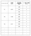
図14~図16はそれぞれ、記憶装置1008に記憶されるプリンタ情報DB1100、バーコードリーダ情報DB1200及び用紙情報DB1300の一例を示す図である。Figures 14 to 16 are diagrams showing examples of the
プリンタ情報DB1100は、プリンタ1005の機種、各機種において選択可能な品質設定及びその品質設定における印刷解像度についての情報を紐づけて管理している。例えば、機種P1のプリンタは、選択可能な品質設定として「きれい」及び「標準」が設けられている。そして、「きれい」の場合の印刷解像度が2400dpi、「標準」の場合の印刷解像度が1200dpiである。The printer information DB 1100 links and manages information about the model of the
バーコードリーダ情報DB1200は、バーコードリーダ1500の機種、各機種の分解能、プリンタの印刷解像度毎のバー幅の下限値についての情報を紐づけて管理している。例えば、機種R1のバーコードリーダは、分解能が0.076mmであり、バーコードを印刷するプリンタの印刷解像度が1200dpiの場合にはバーコードを構成するバーの幅の読み取り可能な下限値が4ピクセルである。このように、下限値は、バーコードリーダ1500による読み取り精度を向上、維持するために設定され得る。The barcode
用紙情報DB1300は、印刷対象の用紙の種類、バーコードフォント及びバー幅の下限値についての情報を紐づけて管理している。例えば、印刷に用いられる用紙が薄紙、バーコードフォントがCODE128の場合、バー幅の下限値は8ピクセルである。The
なお、図14~図16で示す各DBが管理する情報は例示であって、各DBはその他の情報を含み得る。また、一実施形態において、プリンタ情報DB1100、バーコードリーダ情報DB1200及び用紙情報DB1300は、外部サーバ1002で管理されてもよい。その場合、情報処理装置1004は、ネットワーク1003を介して各DBの情報を取得し得る。Note that the information managed by each DB shown in Figures 14 to 16 is an example, and each DB may include other information. In one embodiment, the
後処理装置1400は、バーコードの読み取りを行う読取装置としてのバーコードリーダ1500を含み、バーコードの読み取り結果に応じて所定の処理を実行可能である。所定の処理としては、例えばバーコードの読み取り結果に応じた製品の在庫状況の管理等が挙げられる。The
なお、図1に示す印刷システム1000の構成は一例であり、別の構成も採用可能である。例えば、情報処理装置1004が、モニタ1006、入力装置1007、記憶装置1008を含む構成でも構わない。また、印刷システムが外部サーバ1002を情報処理装置1004が実行する処理の一部を外部サーバ1002が実行してもよい。換言すれば、一実施形態において、印刷システムが外部サーバ1002を含んで構成されてもよい。また、情報処理装置1004は、入力装置1007が受け付けるユーザの入力に限らず、情報処理装置1001や外部サーバ1002からの指示に基づいて、後述のバーコードの生成処理等の各種の処理を実行可能である。The configuration of the
<バーコード生成アプリケーションの構成例>
図2は、バーコード生成アプリケーション90(以下、アプリケーション90)のソフトウェアの構成例を示す。例えば、CPU1011がROM1009に記憶されているプログラムをRAM1010に読み出して実行することによってアプリケーション90の各機能が実現される。 <Example of barcode generation application configuration>
2 shows an example of the software configuration of a barcode generation application 90 (hereinafter, application 90). For example, the
情報取得部901は、各種情報を取得する。例えば、情報取得部901は、バーコード11の構成情報やバーコード11が印刷される印刷領域の情報を取得する。例えば、情報取得部901は、バーコード11又は印刷領域の大きさに関する情報、具体的にはバーコード11又は印刷領域の全体幅や高さ等の情報を取得し得る。また例えば、情報取得部901は、バーコード11を構成するバーの幅の下限値Lについての情報を取得し得る。また例えば、情報取得部901は、バーコード11の種類やバーコード11に変換される数字やアルファベット等の文字列の情報、及び、バーコードのフォントサイズ等の情報を取得し得る。The
また、情報取得部901は、画像データ生成部902が生成した画像データが出力される先のプリンタ1005の情報を取得し得る。一実施形態において、情報取得部901は、記憶装置1008で管理されているプリンタ情報DB1100からプリンタ1005の種類に応じた情報を取得する。また、一実施形態において、情報取得部901は、プリンタ1005から現在の設定情報等やジョブの実行状況等を取得する。The
また、情報取得部901は、プリンタ1005が印刷したバーコード11を読み取るバーコードリーダ1500の情報を取得する。一実施形態において、情報取得部901は、記憶装置1008で管理されているバーコードリーダ情報DB1200からプリンタ1005の種類に応じた情報を取得する。また、一実施形態において、情報取得部901は、後処理装置1400と通信することでバーコードリーダ1500の設定情報等を取得する。The
また、情報取得部901は、プリンタ1005が印刷を行う用紙の種類についての情報を取得する。一実施形態において、情報取得部901は、プリンタ1005から印刷する用紙の種類を取得し、取得した用紙の種類に関する情報を記憶装置1008で管理されている用紙情報DB1300から取得する。The
画像データ生成部902は、印刷媒体上の印刷領域にバーコード11を印刷するための画像データを生成する。画像データ生成部902は、バーコード11の読み取りに関する所定の条件を満たす場合に、情報取得部901が取得した情報に基づく大きさのバーコード11の画像データを生成する。具体的な処理については後述する。The image
下限値設定部903は、画像データ生成部902がバーコード11の画像データを生成する際の、バーコード11を構成するバーの幅の下限値Lを設定する。本実施形態では、下限値Lを、入力装置1007が受け付けたユーザの入力に基づき設定する。The lower
報知指示部904は、ユーザに対して報知を行う報知装置としてのモニタ1006に対して報知を指示する。例えば、報知指示部904は、画像データ生成部902により生成される画像データが所定の条件を満たさない場合にモニタ1006に報知を指示する。図6は、報知指示部904がモニタ1006に表示させる画面の構成例を示す図である。なお、報知指示部904が報知指示を行う対象はモニタ1006に限らず、報知指示部904がスピーカ等に音声出力を指示してもよい。また、本実施形態では、報知指示部904は情報処理装置1004に接続するモニタ1006に対して指示を行うが、情報処理装置1004がモニタやスピーカ等を備える場合には、情報処理装置1004内で報知指示を行ってもよい。The
画像データ出力部905は、画像データ生成部902が生成した画像データをプリンタ1005等の出力先の装置へと出力する。The image
なお、図2に示すアプリケーション90の各機能部は例示であって、一部の機能部が省略されたり、他の機能部に統合されたりしてもよい。Note that the functional units of
<バーコードの構成例>
図7及び図8を用いてバーコード11の構成例を説明する。図7はバーコード11の構成例を説明する図であり、図8はバーコードパターンの一例を説明する図である。なお、バーコードはCODE39やCODE128等、様々な種類が存在するが、ここではCODE128を例に説明する。 <Barcode configuration example>
An example of the structure of the
バーコード11の種類がCODE128である場合、バーコード11は、幅方向の両端のクワイエットゾーンと、その内側のスタートコード、文字列を表すデータ、チェックデジット及びストップコードとで構成される。When the type of
クワイエットゾーンは、バーコードの読み取り不良を防止することを目的として、バーコードの前後に設けられる白地の余白部分である。クワイエットゾーンの幅は、定数値として設定されてもよいし、算出された1本のバー幅に基づいて設定されてもよい。スタートコード及びストップコードは、データの始まりと終わりを表し、バーコードリーダによりバーコードを読み取る際の基準となる部分である。また、チェックデジットは、文字列を表すデータの直後に配置され、符号化されたバーコードのデータが正しいかどうかを確認するための部分である。The quiet zone is a blank area provided before and after a barcode to prevent failure to read the barcode. The width of the quiet zone may be set as a constant value, or may be set based on the calculated width of one bar. The start code and stop code indicate the beginning and end of the data, and are the reference points when reading the barcode with a barcode reader. The check digit is placed immediately after the data representing the character string, and is used to check whether the encoded barcode data is correct.
データは、バーコードに変換された文字列を表す。図8に示すように、文字列を構成する各文字は、3つのバー(印刷部)と3つのスペース(余白)により表される。具体的には、文字コードに対応する11桁のバーコードパターンが規格として用意されており、これらのバーコードパターンに応じた太さのバー(印刷部)とスペース(余白)に変換されることで文字列が表される。例えば、文字“0”を表すバーコードパターンは“10011101100”であり、図8の拡大図に示すようなバーコードに変換される。なお、本例ではバーコードパターンに含まれる数値”1”が印刷部分、数値”0”が非印刷部分、すなわち白地部分を示しており、バーコードパターン上で”1”が連続するほどバーが太くなり、”0”が連続するほどバーの間隔が広くなる。The data represents a character string converted into a barcode. As shown in FIG. 8, each character that makes up the character string is represented by three bars (printed parts) and three spaces (blank spaces). Specifically, a standard 11-digit barcode pattern corresponding to the character code is prepared, and the character string is represented by converting it into bars (printed parts) and spaces (blank spaces) of a thickness corresponding to these barcode patterns. For example, the barcode pattern representing the character "0" is "10011101100", which is converted into a barcode as shown in the enlarged view of FIG. 8. In this example, the number "1" included in the barcode pattern indicates the printed part, and the number "0" indicates the non-printed part, i.e., the white part. The more consecutive "1"s there are on the barcode pattern, the thicker the bar will be, and the more consecutive "0"s there are, the wider the interval between the bars will be.
また、スタートコード及びストップコードについてもバーコードパターンが規格として用意されており、CODE128の場合は、スタートコードは11桁、ストップコードは13桁のバーコードパターンが設定されている。Also, barcode patterns are provided as standards for start and stop codes, and in the case of CODE128, the start code is set to an 11-digit barcode pattern, and the stop code is set to a 13-digit barcode pattern.
チェックデジットは、例えばCODE128の場合はモジュラス103を使用して算出される。なお、モジュラス103の計算は、各キャラクタを対応する数値に換算した後、スタートコードに1を積算し、次の文字列から順に1、2、3…と積算してこれらの合計を求め、合計値を103で除算した剰余としてチェックデジットが得られる。例えば、バーコードに変換する文字列が“012345”の場合は“98”が算出される。For example, in the case of CODE 128, the check digit is calculated using modulus 103. Note that modulus 103 is calculated by converting each character to its corresponding numeric value, multiplying the start code by 1, and then multiplying the next character string by 1, 2, 3, etc. to find the sum of these, and then dividing the sum by 103 to obtain the check digit as the remainder. For example, if the character string to be converted into a barcode is "012345", "98" is calculated.
本実施形態では、バーコードパターンの総桁数は、スタートコードが11桁、文字列が6文字×11桁=66桁、チェックデジットが11桁、ストップコードが13桁であり、クワイエットゾーンを例えば8桁と設定すると、117桁である。これをバーコードの印刷領域の幅Wで除算することでバーコードパターンの1桁当たりの幅方向のピクセル数を算出することができる。例えば、印刷領域の幅Wが708ピクセルの場合、バーコードパターンの1桁当たりのピクセル数=6ピクセルが算出される。この1桁当たりのピクセル数は、バーコードを構成し得るバーの最小幅Bに対応する。すなわち、印刷領域の幅Wをバーコードパターンの総桁数で割ることにより、バーの最小幅Bが算出される。上記の例では、バーの最小幅B=バーコードパターンの1桁当たりのピクセル数=6ピクセルとなる。In this embodiment, the total number of digits in the barcode pattern is 11 digits for the start code, 6 characters x 11 digits = 66 digits for the character string, 11 digits for the check digit, and 13 digits for the stop code. If the quiet zone is set to, for example, 8 digits, the total number of digits is 117 digits. By dividing this by the width W of the printing area of the barcode, the number of pixels in the width direction per digit of the barcode pattern can be calculated. For example, if the width W of the printing area is 708 pixels, the number of pixels per digit of the barcode pattern = 6 pixels is calculated. This number of pixels per digit corresponds to the minimum width B of the bar that can constitute the barcode. In other words, the minimum width B of the bar is calculated by dividing the width W of the printing area by the total number of digits in the barcode pattern. In the above example, the minimum width B of the bar = the number of pixels per digit of the barcode pattern = 6 pixels.
なお、本実施形態では、印刷領域の幅Wをバーコードパターンの桁数で割ることにより1桁当たりのピクセル数を出していることから、印刷領域の幅Wがバーコードの全体幅に対応する。別の観点から見れば、印刷領域の幅W及び高さHはそれぞれ、バーコード全体幅及び高さに対応し、バーコード11の大きさに関する情報であるといえる。In this embodiment, the number of pixels per digit is calculated by dividing the width W of the print area by the number of digits in the barcode pattern, so the width W of the print area corresponds to the overall width of the barcode. From another perspective, the width W and height H of the print area correspond to the overall width and height of the barcode, respectively, and can be said to be information regarding the size of the
<バーコード生成アプリケーションの処理例>
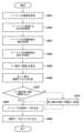
図3は、アプリケーション90の処理例を示すフローチャートである。例えば、情報処理装置1004において、アプリケーション90が起動されると、図3のフローチャートの処理が開始される。なお、本実施形態のフローチャートの各ステップは、CPU1011が、フローチャートの処理に関わるプログラムをメモリから読み出して実行することで実現される。 <Barcode generation application processing example>
Fig. 3 is a flowchart showing an example of processing of the
S101で、情報取得部901は、バーコードの種類を取得する。例えば、情報取得部901は、入力装置1007が受け付けた、ユーザによるバーコードの種類を入力装置1007から受信することにより、バーコードの種類の選択結果を取得する。バーコードの種類としては、例えば、上述のCODE128やCODE39等が挙げられる。選択されたバーコードの種類によってバーコードの生成ロジックが異なることから、アプリケーション90はS101での取得結果に基づいて対応する以下の処理を行う。なお、以下ではCODE128が選択された場合の例を説明する。In S101, the
S102で、情報取得部901は、バーコードに変換する文字列を取得する。例えば、情報取得部901は、入力装置1007が受け付けた、ユーザによる文字列の入力結果を入力装置1007から受信することにより、バーコードに変換する文字列を取得する。バーコードに変換する文字列は、例えば、“012345”等、バーコードの種類に応じた文字から選択された文字列であり得る。In S102, the
S103で、情報取得部901は、バーコードの印刷領域の幅を示す幅情報として、幅Wを取得する。また、S104で、情報取得部901は、バーコードの印刷領域の高さを示す高さ情報として、高さHを取得する。例えば、情報取得部901は、入力装置1007が受け付けた、ユーザによる印刷領域の幅W及び高さHの選択結果を入力装置1007から受信することにより、印刷領域の幅W及び高さHを取得する。In S103, the
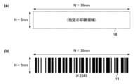
図4(a)は、バーコード11の印刷領域10の一例を示す図である。図4(a)の例では、幅W=30mm、高さH=5mmと設定されている。これは、例えばバーコード11が600dpiにて描画される場合に、それぞれ幅W=708ピクセル、高さH=118ピクセルに相当する。なお、幅Wや高さHは初期値が設定されてもよく、情報取得部901は、入力装置1007が印刷領域の幅W及び高さHの入力を受け付けなかった場合には初期値を印刷領域の幅W及び高さHとして取得してもよい。また、例示した描画される解像度600dpiは初期値として設定されていてもよいし、任意の値に設定可能であってもよい。Figure 4(a) is a diagram showing an example of the
S105で、下限値設定部903は、バーコード11を構成するバーの幅の下限値Lを設定する。例えば、情報取得部901は、入力装置1007が受け付けた、ユーザによる下限値Lの入力結果を入力装置1007から受信して、下限値Lを設定する。なお、バー幅の下限値Lは初期値が設定されてもよく、入力装置1007が下限値Lの入力を受け付けなかった場合には初期値を下限値Lに設定してもよい。一実施形態において、下限値Lの初期値=2ピクセルと設定されてもよい。なお、以下では、下限値L=2ピクセルと設定された場合について説明する。In S105, the lower
S106で、画像データ生成部902は、バーコード11を構成するバーそれぞれの幅を描画ピクセル単位で計算する。図8で説明したように、バーの幅は、バーコードパターンの桁数、文字列の情報及びバーコードの印刷領域の幅Wに基づき計算可能である。In S106, the image
S107で、画像データ生成部902は、S106で算出したバーの幅のうち最小幅Bが下限値L以上(下限値以上)であるか否かを判定し、最小幅Bが下限値L以上の場合にはS108に進み、最小幅Bが下限値Lに満たない場合はS110に進む。In S107, the image
S108で、画像データ生成部902は、バーコード11の画像データを生成する。すなわち、画像データ生成部902は、バーコードの読み取りに関する所定の条件として、最小幅Bが下限値L以上であるという条件を満たす場合にバーコード11の画像データを生成する。例えば、画像データ生成部902は、S102、S103、S104で取得した情報や、S106での計算結果等に基づいて、図4(b)のようなバーコード11の生成を行う(S108)。 例えば、画像データ生成部902は、S103で取得した幅情報に基づく幅、及びS104で取得した高さ情報に基づく高さであるバーを含むバーコードの画像データを生成する。In S108, the image
S109で、画像データ出力部905は、S108で画像データ生成部902が生成した画像データをプリンタ1005に出力する。これにより、画像データを受信したプリンタ1005は、受信した画像データに基づきバーコード11を印刷媒体上の印刷領域に印刷することができる。印刷されたバーコードは、後処理装置1400等による後工程の処理に使用される。In S109, the image
ある側面から見れば、画像データ出力部905は、画像データ生成部902により生成された画像データに基づき、プリンタ1005にバーコード11を印刷領域へ印刷させる印刷制御を行っているといえる。また、画像データ出力部905は、バーコードの読み取りに関する所定の条件として、S106で算出したバーの幅のうち最小幅Bが下限値L以上であることを満たす場合(S107:Yes)に、プリンタ1005にバーコード11を印刷させているといえる。From one perspective, the image
以下、上記フローチャートにより画像データが生成され、印刷されたバーコードの構成について説明する。
図4(b)は、画像データ生成部902が生成した画像データに基づきプリンタ1005が印刷したバーコード11の一例を示す図である。本実施形態では、画像データ生成部902は、印刷領域の幅W及び高さHと同一の幅及び高さを有するバーコードの画像データを生成する。言い換えれば、本実施形態では、画像データ生成部902は、印刷領域の幅Wに収まる範囲内で最大の幅及び高さを有するバーコードの画像データを生成する。 The following describes the structure of a barcode printed when image data is generated according to the above flow chart.
4B is a diagram showing an example of a
一方、S110で、報知指示部904は、報知装置としてモニタ1006に報知を指示する。例えば報知指示部904は、図6で示す画面を表示するようにモニタ1006に対して指示を行う。これにより、バーコードのバー幅が下限値Lよりも小さい場合にバーコードの画像データがプリンタに出力されることなく、その旨をユーザに報知することができる。Meanwhile, in S110, the
図5(a)ないし(d)は、図4(b)の例と同様の文字列“012345”を異なる印刷領域の幅Wでバーコード化した際の印刷例を表している。具体的には、図5(a)は幅W=50mm、図5(b)は幅W=30mm、図5(c)は幅W=10mm、図5(d)は幅W=8mmを取得した際のバーコードの印刷例を示している。これらの場合において、S106で算出される最小幅Bは、順に11ピクセル、6ピクセル、2ピクセル、1ピクセルとなる。ここで、本例では下限値L=2ピクセルと設定されていることから、図5(d)では最小幅B≧下限値Lを満たさず(S107:No)、バーコードの画像データは生成されずに図6の警告メッセージがモニタ1006に表示される(S110)。Figures 5(a) to (d) show examples of printing when the character string "012345" similar to the example of Figure 4(b) is barcoded with different widths W of the print area. Specifically, Figure 5(a) shows a print example of a barcode when the width W is acquired as W = 50 mm, Figure 5(b) shows a print example of a barcode when the width W is acquired as W = 30 mm, Figure 5(c) shows a print example of a barcode when the width W is acquired as W = 10 mm, and Figure 5(d) shows a print example of a barcode when the width W is acquired as W = 8 mm. In these cases, the minimum width B calculated in S106 is 11 pixels, 6 pixels, 2 pixels, and 1 pixel, respectively. Here, since the lower limit L is set as 2 pixels in this example, in Figure 5(d), the minimum width B ≧ lower limit L is not satisfied (S107: No), and image data of the barcode is not generated and the warning message of Figure 6 is displayed on the monitor 1006 (S110).
なお、バーコードリーダ1500において、バーコードに含まれるデータの総桁数が設定されている。そして、バーコードリーダ1500は、総桁数をバーコードの印刷領域の幅Wで除算することで、1桁に対応するバー幅を算出し、算出された幅に基づき、バーコードが示すデータを判定する。そのため、バーコードリーダ1500は、バーコードにおいて数値”1”(印刷部分)が連続した場合に、その印刷部分が何桁の数値に対応するのか判定することができる。従って、図5(a)~(c)で1桁に対応するバーの幅は異なるが、バーコードリーダ1500は図5(a)~(c)から同一のデータを得ることができる。また、バーコードリーダが1桁に対応するバー幅を算出する方法は上記方法に限らない。例えば、スタートコードおよびストップコードは、予め決められた情報である。そのため、バーコードリーダ1500は、読み取ったバーコードにおける最初の部分とスタートコードのバーコードパターンを比較することで、1桁当たりのバー幅を算出してもよい。或いは、バーコードリーダ1500は、読み取ったバーコードにおける最後の部分とストップコードのバーコードパターンを比較することで、1桁当たりのバー幅を算出してもよい。In addition, the total number of digits of data contained in the barcode is set in the
以上説明したように、本実施形態によれば、画像データ生成部902は、バーコード11の読み取りに関する所定の条件を満たす場合に、バーコードの大きさに関する情報である印刷領域の幅及び高さに基づく大きさのバーコードの画像データを生成する。具体的には、所定の条件として最小幅Bが下限値L以上である場合に画像データを生成する。これにより、読み取り精度を維持しつつ所望のサイズでバーコードが印刷されるので、適切なサイズでバーコードを印刷することができる。As described above, according to this embodiment, when a specific condition related to reading the
また、本実施形態では、印刷領域の幅W及び高さHについてのユーザの入力を受け付けるので、任意の大きさでバーコードを生成することができる。換言すれば、バーコードの大きさに対応する印刷領域の幅W及び高さHがそれぞれ独立に設定された場合であっても、設定されたサイズでバーコードを生成することができる。また、本実施形態では、印刷領域に収まる範囲で最大の幅でバーコードを描画することで、バー(印刷部)とスペース(余白)を可能な限り大きくし、バーコードリーダ1500による読み取り精度を向上することができる。In addition, in this embodiment, since the width W and height H of the print area are input by the user, a barcode can be generated in any size. In other words, even if the width W and height H of the print area corresponding to the size of the barcode are set independently, a barcode can be generated in the set size. In addition, in this embodiment, the barcode is drawn with the maximum width that fits within the print area, making the bars (printed area) and spaces (margins) as large as possible, improving the reading accuracy of the
なお、情報取得部901による各種情報の取得順序は、適宜変更可能である。また、情報取得部901は、取得する情報を一括で入力装置1007から受信してもよい。The order in which the
<第2実施形態>
第2実施形態に係る構成について説明する。なお、第1実施形態と同様の構成については同様の符号を付して説明を省略する。第2実施形態では、バーコードを構成するバーの最小幅Bが下限値Lに満たない場合の処理が第1実施形態と異なる。 Second Embodiment
The configuration according to the second embodiment will be described. Note that the same components as those in the first embodiment are denoted by the same reference numerals and will not be described. In the second embodiment, the process when the minimum width B of the bars constituting the barcode is less than the lower limit L is different from that in the first embodiment.
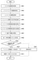
図9は、一実施形態に係るアプリケーション90の処理例を示すフローチャートである。S201~S209の処理は図3のS101~S109の処理と同様である。Figure 9 is a flowchart showing an example of processing of
S210に進んだ場合、すなわち最小幅Bが下限値Lよりも小さい場合、画像データ生成部902は、最小幅Bの値を下限値Lの値に変更する。換言すれば、最小幅Bに下限値Lを代入する。画像データ生成部902は、その後S209の処理に進み画像データを生成する。つまり、画像データ生成部902は、最小幅Bが下限値Lよりも小さい場合であっても、画像データの生成を中止するのではなく、最小幅Bの値を下限値Lの値に変更し、読み取り可能な最小のバー幅Lでバーコードの画像データの生成を行う。If the process proceeds to S210, i.e., if the minimum width B is smaller than the lower limit L, the image
図10(d)は、S210の処理の後に画像データが生成された場合における、バーコードの印刷結果の一例を示す図である。ここでは、S203で取得した印刷領域幅Wが8mmであり、S206で計算された最小幅Bは1ピクセルであり、S205で設定された下限値Lは2ピクセルであった場合について説明する。この場合、画像データ生成部902は、最小幅B<下限値Lより、S207からS208に進む。そして、画像データ生成部902は、S208で最小幅Bを1ピクセルから2ピクセルに変更する。上述のように、最小幅Bはバーコードパターンの1桁当たりのピクセル数に対応することから、この変更に応じてバーコードパターンの1桁当たりのピクセル数も1ピクセルから2ピクセルに変更される。よって、バーコードの全体幅も変更前よりも大きくなる。そのため、図10(d)に示すように、指定された印刷領域の範囲外まで幅方向に延びたバーコードが印刷される。これにより、警告メッセージが表示されることなく、指定の印刷領域外にバーコードが生成される。Figure 10(d) is a diagram showing an example of a barcode print result when image data is generated after the process of S210. Here, a case will be described where the print area width W acquired in S203 is 8 mm, the minimum width B calculated in S206 is 1 pixel, and the lower limit value L set in S205 is 2 pixels. In this case, the image
本実施形態によれば、幅方向の印刷領域に余裕がある印刷物等の場合、ユーザへの報知を行うことなく、かつ読み取り精度を確保できる程度にバーコードを幅方向に拡大して印刷を行うことで、効率的にバーコードの印刷を行うことができる。According to this embodiment, in the case of printed matter with ample print area in the width direction, the barcode can be printed efficiently by enlarging it in the width direction without notifying the user and while still ensuring reading accuracy.
また、バーコード印刷領域の幅Wに初期値が設定されている場合、入力される文字列の文字数が多い場合には最小幅Bが小さくなってしまい、最小幅B≧下限値Lの条件が満たされにくくなる場合がある。しかしながら、本実施形態によれば、このような場合に第1実施形態のようにユーザへ報知をすることなく、バーコードの生成を優先することができる。In addition, if an initial value is set for the width W of the barcode printing area, the minimum width B may become small if the number of characters in the input string is large, making it difficult to satisfy the condition of minimum width B ≧ lower limit L. However, according to this embodiment, in such cases, it is possible to prioritize the generation of the barcode without notifying the user as in the first embodiment.
なお、指定の印刷領域外にバーコードを印刷すると、別の印刷対象と干渉が生じる場合、報知指示部904はモニタ1006等に対して警告メッセージを表示させてもよい。Note that if printing a barcode outside the designated printing area causes interference with another printing target, the
<第3実施形態>
次に、第3実施形態について、図11及び図12を用いて説明する。なお、第1実施形態と同様の構成については同様の符号を付して説明を省略する。第3実施形態ではバーコードのフォントサイズに基づいてバーコードを生成する点で第1実施形態と異なる。第1実施形態では印刷領域の幅Wに基づいて各バーの幅を計算してバーコードを生成する。一方、第3実施形態ではバーコードフォントのポイント設定を活用してバーコードの全体幅を設定し、高さ方向において印刷領域からはみ出す部分を印刷させないようにバーコードを生成する。 Third Embodiment
Next, the third embodiment will be described with reference to Figures 11 and 12. Note that the same components as those in the first embodiment are given the same reference numerals and the description will be omitted. The third embodiment differs from the first embodiment in that a barcode is generated based on the barcode font size. In the first embodiment, the width of each bar is calculated based on the width W of the print area to generate a barcode. On the other hand, in the third embodiment, the point setting of the barcode font is used to set the overall width of the barcode, and the barcode is generated so that the portion that protrudes from the print area in the height direction is not printed.
図11は、一実施形態に係るアプリケーション90の処理例を示すフローチャートである。S301~S305は、S101~S105と同様である。Figure 11 is a flowchart showing an example of processing of
S306で、画像データ生成部902は、バーコードのフォントポイントを設定する。具体的には、画像データ生成部902は、印刷されたバーコードが印刷領域の幅W内に収まるバーコードフォントのポイントのうち、最大の値をフォントポイントとして設定する。In S306, the image
S307で、画像データ生成部902は、S306で設定されたフォントポイントに基づいて、バーコード11を構成するバーそれぞれの幅を描画ピクセル単位で計算する。In S307, the image
S308で、画像データ生成部902は、S307で算出したバーの幅のうち最小幅Bが下限値L以上であるか否かを判定し、最小幅Bが下限値L以上の場合にはS309に進み、最小幅Bが下限値Lに満たない場合はS311に進む。なお、S311はS110と同様である。In S308, the image
S309で、画像データ生成部902は、バーコード11の画像データを生成する。
S310で、画像データ生成部902は、画像データにより印刷されるバーコード11が高さ方向で印刷領域に収まるように画像データを補正する。S309で生成された画像データにより印刷されるバーコード11は、S306の処理により幅方向について印刷領域に収まっているが、高さ方向については印刷領域に収まっている場合と収まっていない場合がある。そこで、画像データ生成部902は、画像データにより印刷されるバーコードが高さ方向で印刷領域に収まらない場合には、印刷領域に収まらない部分が印刷されないように画像データを補正する。 In S309, the image
In S310, the image
画像データの補正の方法としては、画像データのうち印刷領域外に対応する部分を白地で上塗りすることが挙げられる。例えば、画像データがビットマップ形式であれば、印刷領域外を白に対応する値(例えば0)に変更する補正を行ってもよい。また、補正の方法としては、印刷領域に収まるように画像データの高さ方向の大きさ自体を変更することが挙げられる。例えば、バーコードが印刷領域に収まるように高さ方向のピクセル数を変更する補正を行ってもよい。なお、補正をしなくとも画像データにより印刷されるバーコードが印刷領域に収まる場合はS310を省略してもよい。One method of correcting the image data is to overlay the parts of the image data that correspond to outside the print area with a white background. For example, if the image data is in bitmap format, a correction may be made to change the parts outside the print area to a value that corresponds to white (e.g., 0). Another correction method is to change the height of the image data itself so that it fits within the print area. For example, a correction may be made to change the number of pixels in the height direction so that the barcode fits within the print area. Note that if the barcode printed from the image data fits within the print area without correction, S310 may be omitted.
図12(a)ないし(d)は、フォントポイントに基づいてバーコードを印刷する場合の説明図である。図12(a)で示す指定の印刷領域の幅Wに合わせたフォントポイントが設定された場合(S306)、そのままバーコードの画像データを生成して印刷すると、バーコードが高さ方向で指定の印刷領域に収まらない場合がある(図12(b))。本実施形態では、このような場合に印刷領域に収まらない部分が印刷されないように画像データが補正される(S310)。具体的には、図12(c)の領域12が実際には印刷されないように画像データが補正される。これにより、最終的に指定の印刷領域に収まるバーコード11がプリンタ1005により印刷される。Figures 12(a) to (d) are explanatory diagrams for printing a barcode based on font points. When font points are set to match the width W of the specified print area shown in Figure 12(a) (S306), if image data for the barcode is generated and printed as is, the barcode may not fit within the specified print area in the height direction (Figure 12(b)). In this embodiment, in such a case, the image data is corrected so that the portion that does not fit within the print area is not printed (S310). Specifically, the image data is corrected so that area 12 in Figure 12(c) is not actually printed. As a result, the
以上説明したように、本実施形態によれば、規格等によって定められているバーコードのポイント設定に基づいて画像データを生成することができる。したがって、ユーザによる印刷領域の幅方向のサイズの設定に応じてその都度バーコードのバーの幅を算出する必要が無く、より効率的にバーコードの生成処理を行うことができる。As described above, according to this embodiment, image data can be generated based on barcode point settings defined by standards, etc. Therefore, there is no need to calculate the width of the barcode bars each time depending on the width size of the print area set by the user, and the barcode generation process can be performed more efficiently.
<第4実施形態>
次に第4実施形態について、図13~図15を用いて説明する。なお、第1実施形態と同様の構成については同様の符号を付して説明を省略する。第4実施形態は、下限値Lを、バーコードを印刷するプリンタの解像度と、バーコードを読み取るバーコードリーダの分解能と、基づいて設定する点で第1実施形態と異なる。 Fourth Embodiment
Next, a fourth embodiment will be described with reference to Figures 13 to 15. Note that the same components as those in the first embodiment are denoted by the same reference numerals and will not be described. The fourth embodiment differs from the first embodiment in that the lower limit L is set based on the resolution of the printer that prints the barcode and the resolution of the barcode reader that reads the barcode.
図13はアプリケーション90の処理例を示すフローチャートである。
S401で、情報取得部901は、画像データの出力先となるプリンタ1005の解像度を取得する。例えば、アプリケーション90は、入力装置1007を介してユーザによるプリンタ1005の種類の情報を取得し、それに基づいてバーコードリーダ情報DB1200を参照して対象となるプリンタ1005の種類の解像度の情報を取得してもよい。また例えば、アプリケーション90は、プリンタ1005との通信により解像度の設定情報を取得してもよい。また例えば、アプリケーション90は、入力装置1007を介してユーザによる解像度の設定情報の入力を受け付けてもよい。 FIG. 13 is a flowchart showing an example of processing by the
In S401, the
S402で、情報取得部901は、使用するバーコードリーダ1500の種類を取得する。例えば、情報取得部901は、入力装置1007を介して使用するバーコードリーダ1500の種類の情報を取得する。また、情報取得部901は、取得したバーコードリーダ1500の種類に基づいて、バーコードリーダ情報DB1200を参照して対象となるバーコードリーダ1500の分解能を取得してもよい。すなわち、情報取得部901は、バーコードリーダ1500の種類を取得することにより、それに紐づくバーコードリーダ1500の分解能を取得する。なお、情報取得部901は、後処理装置1400との通信により分解能の設定情報を取得してもよい。また、アプリケーション90は、入力装置1007を介してユーザによる分解能の設定情報の入力を受け付けてもよい。In S402, the
S403~S406はそれぞれ、S101~S104と同様である。S403 to S406 are the same as S101 to S104, respectively.
S407で、下限値設定部903は、バーコードを構成するバーの幅の下限値Lを設定する。本実施形態では、下限値設定部903は、S401及び402で設定したプリンタの解像度及びバーコードリーダの分解能から、バー幅の下限値Lを設定する。例えば、下限値設定部903は、図15に一例として示すバーコードリーダ情報DB1200の一覧から、プリンタ1005の解像度及びバーコードリーダ1500の分解能(あるいは種類)を考慮した下限値Lを設定する。なお、下限値設定部903は、所定の計算式に基づいて、取得したプリンタ1005の解像度及びバーコードリーダ1500の分解能から下限値Lを設定してもよい。In S407, the lower
なお、プリンタ1005の解像度及びバーコードリーダ1500の分解能に加え、印刷媒体についての情報も考慮して下限値Lを設定してもよい。例えば、下限値設定部903は、図16に一覧として示す用紙情報DB1300を参照し、プリンタ1005により印刷がなされる用紙の種類及びバーコードフォントに基づいて下限値Lを取得してもよい。そして、下限値設定部903は、バーコードリーダ情報DB1200を参照して取得した下限値と用紙情報DBを参照して取得した下限値の大きい方を下限値Lとして設定してもよい。In addition to the resolution of the
S408~S412はそれぞれ、S106~S110と同様である。S408 to S412 are the same as S106 to S110, respectively.
以上説明したように、本実施形態では、使用するプリンタ及びバーコードリーダに基づいて、バー幅の下限値Lを設定することができる。これにより、バーコードの読み取り不良を抑制することができ、バーコードリーダによるバーコードの読み取り精度を向上することができる。As described above, in this embodiment, the lower limit L of the bar width can be set based on the printer and barcode reader being used. This can reduce barcode reading errors and improve the accuracy of barcode reading by the barcode reader.
<他の実施形態>
アプリケーション90は、上記実施形態の処理を適宜組み合わせて実行してもよい。例えば、ユーザの操作によりいずれの処理を実行するかを選択可能であってもよいし、一連の処理の中で一部の処理が他の実施形態に係る処理に置き換えられてもよい。例えば、情報取得部901が取得した各種情報に基づいて、最小幅B<下限値Lの場合の処理を切り替えてもよい。 <Other embodiments>
The
また、上記実施形態では、バーコード生成アプリケーション90により各処理が実行されるものとして説明したが、その限りではない。例えば、オブジェクトデータを新たに配置するようなレイアウト編集アプリケーションを用いて上記実施形態の処理が実行されてもよい。In addition, in the above embodiment, each process is described as being executed by the
本発明は、上述の実施形態の1以上の機能を実現するプログラムを、ネットワーク又は記憶媒体を介してシステム又は装置に供給し、そのシステム又は装置のコンピュータにおける1つ以上のプロセッサーがプログラムを読出し実行する処理でも実現可能である。また、1以上の機能を実現する回路(例えば、ASIC)によっても実現可能である。The present invention can also be realized by supplying a program that realizes one or more of the functions of the above-mentioned embodiments to a system or device via a network or storage medium, and having one or more processors in the computer of the system or device read and execute the program. It can also be realized by a circuit (e.g., an ASIC) that realizes one or more functions.
発明は上記実施形態に制限されるものではなく、発明の精神及び範囲から離脱することなく、様々な変更及び変形が可能である。従って、発明の範囲を公にするために請求項を添付する。The invention is not limited to the above-described embodiment, and various modifications and variations are possible without departing from the spirit and scope of the invention. Therefore, the following claims are appended to disclose the scope of the invention.
90 バーコード生成アプリケーション、901 情報取得部、902画像データ生成部、1000 印刷システム90 Barcode generation application, 901 Information acquisition unit, 902 Image data generation unit, 1000 Printing system
Claims (10)
Translated fromJapaneseバーコードが印刷される印刷領域の大きさに関する第1情報を取得する第1取得手段と、
前記第1取得手段が取得した前記第1情報に基づいて、前記印刷領域に印刷されるバーコードの画像データを生成する生成手段と、
前記バーコードを構成するバーの幅の下限値を設定する第1設定手段と、
を備え、
前記第1情報は、前記印刷領域の幅に関する幅情報と、前記印刷領域の高さに関する高さ情報を含み、
前記生成手段は、前記バーコードを構成するバーとして、前記幅情報に基づく幅であり且つ前記高さ情報に基づく高さであるバーを含む画像データを生成し、
前記第1情報は、それぞれ独立に設定された前記バーコードの全体幅及び高さに関する情報を含み、
前記生成手段は、前記バーコードが前記印刷領域に収まる範囲内で、前記バーコードの全体幅及び高さが最大の値となるように、前記画像データを生成し、
前記生成手段は、前記バーコードが前記印刷領域に収まる範囲内で前記画像データを生成すると、前記画像データに基づき印刷される前記バーコードを構成する前記バーの最小幅が、前記第1設定手段により設定された前記下限値よりも小さくなる場合に、前記バーの前記最小幅を前記下限値に変更して前記画像データを生成し、
前記情報処理装置はさらに、
前記生成手段により前記バーの前記最小幅が前記下限値に変更されて前記画像データが生成されて印刷が行われる場合に、前記バーコードが前記印刷領域外まで延びて別の印刷対象と干渉が生じるのであれば、警告を発する報知手段、を備える、
ことを特徴とする情報処理装置。An information processing device,
a first acquiring means for acquiring first information relating to a size of a printing area in which a barcode is printed;
a generating means for generating image data of a barcode to be printed in the printing area based on the first information acquired by the first acquiring means;
a first setting means for setting a lower limit value of the width of the bars constituting the barcode;
Equipped with
the first information includes width information relating to a width of the printing area and height information relating to a height of the printing area,
the generating means generates image data including, as bars constituting the barcode, bars each having a width based on the width information and a height based on the height information;
The first information includes information regarding an overall width and a height of the barcode, the width and the height being set independently of each other ,
the generating means generates the image data so that the overall width and height of the barcode are maximized within a range in which the barcode fits within the printing area;
when the image data is generated within a range in which the barcode fits within the print area, and a minimum width of the bar constituting the barcode printed based on the image data becomes smaller than the lower limit value set by the first setting means, the generating means changes the minimum width of the bar to the lower limit value and generates the image data;
The information processing device further comprises:
a notification means for issuing a warning if the barcode extends outside the printing area and interferes with another printing target when the generation means changes the minimum width of the bar to the lower limit value and generates the image data to be printed,
23. An information processing apparatus comprising:
前記所定の条件は、前記生成手段により生成された前記画像データに基づき印刷される前記バーコードを構成するバーの幅の最小幅が、前記第1設定手段により設定された前記下限値以上であることを含む、
情報処理装置。 4. The information processing device according to claim3,
the predetermined condition includes that a minimum width of a bar constituting the barcode printed based on the image data generated by the generating means is equal to or greater than the lower limit value set by the first setting means;
Information processing device.
前記報知手段はさらに、
前記バーコードを構成するバーの幅の前記最小幅が、前記第1設定手段により設定された前記下限値よりも小さい場合に、前記バーの前記最小幅を前記下限値に変更せずに、ユーザに対して報知を行う、
情報処理装置。 5. The information processing device according to claim4 ,
The notification means further includes:
when the minimum width of the bars constituting the barcode is smaller than the lower limit value set by the first setting means,the minimum width of the bars is not changed to the lower limit value, and a notificationis given to a user.
Information processing device.
前記第1取得手段が取得した前記第1情報に基づいて、前記印刷領域に印刷されるバーコードの画像データを生成する生成手段と、
前記バーコードを構成するバーの幅の下限値を設定する第1設定手段と、
前記生成手段により生成された前記画像データに基づいて印刷を行う印刷手段と、を備え、
前記第1情報は、前記印刷領域の幅に関する幅情報と、前記印刷領域の高さに関する高さ情報を含み、
前記生成手段は、前記バーコードを構成するバーとして、前記幅情報に基づく幅であり且つ前記高さ情報に基づく高さであるバーを含む画像データを生成し、
前記第1情報は、それぞれ独立に設定された前記バーコードの全体幅及び高さに関する情報を含み、
前記生成手段は、前記バーコードが前記印刷領域に収まる範囲内で、前記バーコードの全体幅及び高さが最大の値となるように、前記画像データを生成し、
前記生成手段は、前記バーコードが前記印刷領域に収まる範囲内で前記画像データを生成すると、前記画像データに基づき印刷される前記バーコードを構成する前記バーの最小幅が、前記第1設定手段により設定された前記下限値よりも小さくなる場合に、前記バーの前記最小幅を前記下限値に変更して前記画像データを生成し、
前記生成手段により前記バーの前記最小幅が前記下限値に変更されて前記画像データが生成されて印刷が行われる場合に、前記バーコードが前記印刷領域外まで延びて別の印刷対象と干渉が生じるのであれば、警告を発する報知手段を含む、
印刷システム。 a first acquiring means for acquiring first information relating to a size of a printing area in which a barcode is printed;
a generating means for generating image data of a barcode to be printed in the printing area based on the first information acquired by the first acquiring means;
a first setting means for setting a lower limit value of the width of the bars constituting the barcode;
a printing unit that prints based on the image data generated by the generating unit,
the first information includes width information relating to a width of the printing area and height information relating to a height of the printing area,
the generating meansgenerates image data including, as bars constituting the barcode, bars each having a width based on the width information and a height based on the height information;
The first information includes information regarding an overall width and a height of the barcode, the width and the height being set independently of each other,
the generating means generates the image data so that the overall width and height of the barcode are maximized within a range in which the barcode fits within the printing area;
when the image data is generated within a range in which the barcode fits within the print area, and a minimum width of the bar constituting the barcode printed based on the image data becomes smaller than the lower limit value set by the first setting means, the generating means changes the minimum width of the bar to the lower limit value and generates the image data;
a notification means for issuing a warning if the barcode extends outside the printing area and interferes with another printing target when the generation means changes the minimum width of the bar to the lower limit value, generates the image data, and prints the image data,
Printing system.
バーコードが印刷される印刷領域の大きさに関する第1情報を取得する第1取得工程と、
前記第1取得工程が取得した前記第1情報に基づいて、前記印刷領域に印刷されるバーコードの画像データを生成する生成工程と、
前記バーコードを構成するバーの幅の下限値を設定する第1設定工程と、を含み、
前記第1情報は、前記印刷領域の幅に関する幅情報と、前記印刷領域の高さに関する高さ情報を含み、
前記生成工程は、前記バーコードを構成するバーとして、前記幅情報に基づく幅であり且つ前記高さ情報に基づく高さであるバーを含む画像データを生成し、
前記第1情報は、それぞれ独立に設定された前記バーコードの全体幅及び高さに関する情報を含み、
前記生成工程は、前記バーコードが前記印刷領域に収まる範囲内で、前記バーコードの全体幅及び高さが最大の値となるように、前記画像データを生成し、
前記生成工程は、前記バーコードが前記印刷領域に収まる範囲内で前記画像データを生成すると、前記画像データに基づき印刷される前記バーコードを構成する前記バーの最小幅が、前記第1設定工程により設定された前記下限値よりも小さくなる場合に、前記バーの前記最小幅を前記下限値に変更して前記画像データを生成し、
前記生成工程により前記バーの前記最小幅が前記下限値に変更されて前記画像データが生成されて印刷が行われる場合に、前記バーコードが前記印刷領域外まで延びて別の印刷対象と干渉が生じるのであれば、警告を発する報知工程を含む、
情報処理方法。An information processing method executed by an information processing device,
a first acquisition step of acquiring first information relating to a size of a printing area in which a barcode is printed;
a generating step of generating image data of a barcode to be printed in the printing area based on the first information acquired in the first acquisition step;
a first setting step of setting a lower limit value of the width of the bars constituting the barcode,
the first information includes width information relating to a width of the printing area and height information relating to a height of the printing area,
the generating stepgenerates image data including bars that constitute the barcode, the bars having a width based on the width information and a height based on the height information;
The first information includes information regarding an overall width and a height of the barcode, the width and the height being set independently of each other,
the generating step generates the image data so that the overall width and height of the barcode are maximized within a range in which the barcode fits within the print area;
the generating step generates the image data by changing the minimum width of the bar to the lower limit value when the image data is generated within a range in which the barcode fits within the print area and a minimum width of the bar constituting the barcode printed based on the image data becomes smaller than the lower limit value set in the first setting step;
a notification step of issuing a warning if the barcode extends outside the printing area and interferes with another printing target when the minimum width of the bar is changed to the lower limit value in the generating step and the image data is generated and printed.
Information processing methods.
バーコードが印刷される印刷領域の大きさに関する第1情報を取得する第1取得手段、
前記第1取得手段が取得した前記第1情報に基づいて、前記印刷領域に印刷されるバーコードの画像データを生成する生成手段、
前記バーコードを構成するバーの幅の下限値を設定する第1設定手段、として機能させ、
前記第1情報は、前記印刷領域の幅に関する幅情報と、前記印刷領域の高さに関する高さ情報を含み、
前記生成手段は、前記バーコードを構成するバーとして、前記幅情報に基づく幅であり且つ前記高さ情報に基づく高さであるバーを含む画像データを生成し、
前記第1情報は、それぞれ独立に設定された前記バーコードの全体幅及び高さに関する情報を含み、
前記生成手段は、前記バーコードが前記印刷領域に収まる範囲内で、前記バーコードの全体幅及び高さが最大の値となるように、前記画像データを生成し、
前記生成手段は、前記バーコードが前記印刷領域に収まる範囲内で前記画像データを生成すると、前記画像データに基づき印刷される前記バーコードを構成する前記バーの最小幅が、前記第1設定手段により設定された前記下限値よりも小さくなる場合に、前記バーの前記最小幅を前記下限値に変更して前記画像データを生成し、
前記コンピュータをさらに、
前記生成手段により前記バーの前記最小幅が前記下限値に変更されて前記画像データが生成されて印刷が行われる場合に、前記バーコードが前記印刷領域外まで延びて別の印刷対象と干渉が生じるのであれば、警告を発する報知手段として機能させる、
プログラム。 Computer,
a first acquiring means for acquiring first information relating to the size of a printing area in which a barcode is printed;
a generating means for generating image data of a barcode to be printed in the printing area based on the first information acquired by the first acquiring means;
a first setting means for setting a lower limit value of the width of the bars constituting the barcode;
the first information includes width information relating to a width of the printing area and height information relating to a height of the printing area,
the generating meansgenerates image data including, as bars constituting the barcode, bars each having a width based on the width information and a height based on the height information;
The first information includes information regarding an overall width and a height of the barcode, the width and the height being set independently of each other,
the generating means generates the image data so that the overall width and height of the barcode are maximized within a range in which the barcode fits within the printing area;
when the image data is generated within a range in which the barcode fits within the print area, and a minimum width of the bar constituting the barcode printed based on the image data becomes smaller than the lower limit value set by the first setting means, the generating means changes the minimum width of the bar to the lower limit value and generates the image data;
The computer further comprises:
When the generating means changes the minimum width of the bar to the lower limit value, generates the image data, and prints the image, if the barcode extends outside the printing area and interferes with another printing object, the generating means functions as a notification means for issuing a warning.
program.
Priority Applications (2)
| Application Number | Priority Date | Filing Date | Title |
|---|---|---|---|
| JP2020033748AJP7471864B2 (en) | 2020-02-28 | 2020-02-28 | Information processing device, printing system, information processing method and program |
| US17/177,533US11562154B2 (en) | 2020-02-28 | 2021-02-17 | Information processing apparatus, print system, and information processing method |
Applications Claiming Priority (1)
| Application Number | Priority Date | Filing Date | Title |
|---|---|---|---|
| JP2020033748AJP7471864B2 (en) | 2020-02-28 | 2020-02-28 | Information processing device, printing system, information processing method and program |
Publications (2)
| Publication Number | Publication Date |
|---|---|
| JP2021135927A JP2021135927A (en) | 2021-09-13 |
| JP7471864B2true JP7471864B2 (en) | 2024-04-22 |
Family
ID=77463579
Family Applications (1)
| Application Number | Title | Priority Date | Filing Date |
|---|---|---|---|
| JP2020033748AActiveJP7471864B2 (en) | 2020-02-28 | 2020-02-28 | Information processing device, printing system, information processing method and program |
Country Status (2)
| Country | Link |
|---|---|
| US (1) | US11562154B2 (en) |
| JP (1) | JP7471864B2 (en) |
Families Citing this family (1)
| Publication number | Priority date | Publication date | Assignee | Title |
|---|---|---|---|---|
| JP7598780B2 (en)* | 2021-03-01 | 2024-12-12 | 東芝テック株式会社 | Product registration device and program |
Citations (4)
| Publication number | Priority date | Publication date | Assignee | Title |
|---|---|---|---|---|
| JP2000105794A (en) | 1998-09-29 | 2000-04-11 | Prosper Creative:Kk | Method for printing bag code |
| JP2008176446A (en) | 2007-01-17 | 2008-07-31 | Canon Finetech Inc | Print data processor and print data processing program |
| JP2008305137A (en) | 2007-06-07 | 2008-12-18 | Canon Finetech Inc | Bar-code generation system, bar-code generation program and printer |
| JP2019180047A (en) | 2018-03-30 | 2019-10-17 | ブラザー工業株式会社 | Image processing device and image processing program |
Family Cites Families (11)
| Publication number | Priority date | Publication date | Assignee | Title |
|---|---|---|---|---|
| JPH08310050A (en)* | 1995-05-16 | 1996-11-26 | Fuji Xerox Co Ltd | Bar code printing device |
| JP4281414B2 (en)* | 2003-05-22 | 2009-06-17 | セイコーエプソン株式会社 | Barcode or two-dimensional code printing system, barcode or two-dimensional code font setting method, and barcode or two-dimensional code font setting program |
| US20070176000A1 (en)* | 2006-01-31 | 2007-08-02 | Konica Minolta Systems Laboratory, Inc. | Selective image encoding and replacement |
| JP4923740B2 (en)* | 2006-05-31 | 2012-04-25 | 富士ゼロックス株式会社 | Image processing system, image forming apparatus, and image processing program |
| JP4450840B2 (en)* | 2007-02-26 | 2010-04-14 | キヤノンファインテック株式会社 | Bar code generation apparatus and computer program |
| US20080304891A1 (en)* | 2007-06-07 | 2008-12-11 | Canon Finetech Inc. | Barcode generation system, barcode generation program, and printing device |
| TWI438693B (en)* | 2010-11-12 | 2014-05-21 | Primax Electronics Ltd | Printing control method and printing control apparatus for line light source detection |
| JP6407031B2 (en) | 2015-01-08 | 2018-10-17 | 三菱電機株式会社 | Optical reader and method of manufacturing optical reader |
| CN106022424B (en)* | 2016-05-10 | 2019-04-26 | 腾讯科技(深圳)有限公司 | Generate the method and device with the two-dimension code image of dynamic effect |
| JP6844474B2 (en)* | 2017-08-29 | 2021-03-17 | ブラザー工業株式会社 | Printer driver and information processing device |
| US10546160B2 (en)* | 2018-01-05 | 2020-01-28 | Datamax-O'neil Corporation | Methods, apparatuses, and systems for providing print quality feedback and controlling print quality of machine-readable indicia |
- 2020
- 2020-02-28JPJP2020033748Apatent/JP7471864B2/enactiveActive
- 2021
- 2021-02-17USUS17/177,533patent/US11562154B2/enactiveActive
Patent Citations (4)
| Publication number | Priority date | Publication date | Assignee | Title |
|---|---|---|---|---|
| JP2000105794A (en) | 1998-09-29 | 2000-04-11 | Prosper Creative:Kk | Method for printing bag code |
| JP2008176446A (en) | 2007-01-17 | 2008-07-31 | Canon Finetech Inc | Print data processor and print data processing program |
| JP2008305137A (en) | 2007-06-07 | 2008-12-18 | Canon Finetech Inc | Bar-code generation system, bar-code generation program and printer |
| JP2019180047A (en) | 2018-03-30 | 2019-10-17 | ブラザー工業株式会社 | Image processing device and image processing program |
Also Published As
| Publication number | Publication date |
|---|---|
| US11562154B2 (en) | 2023-01-24 |
| JP2021135927A (en) | 2021-09-13 |
| US20210271829A1 (en) | 2021-09-02 |
Similar Documents
| Publication | Publication Date | Title |
|---|---|---|
| JP6978205B2 (en) | Print control device, raster data generation method, and raster data generation program | |
| JP7471864B2 (en) | Information processing device, printing system, information processing method and program | |
| JP2013167967A (en) | Print controller | |
| JP2008305137A (en) | Bar-code generation system, bar-code generation program and printer | |
| JP2008176446A (en) | Print data processor and print data processing program | |
| EP2149855B1 (en) | Operations information management system | |
| JP7471865B2 (en) | Information processing device, information processing method, and program | |
| JP2000105794A (en) | Method for printing bag code | |
| JP2019180047A (en) | Image processing device and image processing program | |
| JP2010221429A (en) | Label printer and information processor | |
| JP5228569B2 (en) | Variable printing method using web, variable printing system using web, and submitted data processing apparatus | |
| JPH0999590A (en) | Method for creating bar pattern table in bar code printing apparatus and bar code printing apparatus incorporating this table | |
| JP2021160215A (en) | Printing equipment, printing methods and programs | |
| JPH08310050A (en) | Bar code printing device | |
| JP2017001324A (en) | Print control device | |
| JP7647076B2 (en) | IMAGE PROCESSING PROGRAM, IMAGE PROCESSING APPARATUS, AND IMAGE PROCESSING METHOD | |
| JP2019180046A (en) | Image processing device and image processing program | |
| JP3520389B2 (en) | System and method for barcode printing | |
| JP2020003605A (en) | Display control device | |
| JP2009070214A (en) | Business form design system and line pitch automatic adjustment device | |
| JP3008855B2 (en) | Label printer | |
| JP6672666B2 (en) | Information processing apparatus and program | |
| JPS62199459A (en) | Apparatus for processing document | |
| JP2025033898A (en) | Information processing device, control method for information processing device, and program | |
| JP2011210116A (en) | Slip creation device and control program thereof |
Legal Events
| Date | Code | Title | Description |
|---|---|---|---|
| RD01 | Notification of change of attorney | Free format text:JAPANESE INTERMEDIATE CODE: A7421 Effective date:20210103 | |
| A521 | Request for written amendment filed | Free format text:JAPANESE INTERMEDIATE CODE: A523 Effective date:20210113 | |
| A621 | Written request for application examination | Free format text:JAPANESE INTERMEDIATE CODE: A621 Effective date:20230216 | |
| A977 | Report on retrieval | Free format text:JAPANESE INTERMEDIATE CODE: A971007 Effective date:20230929 | |
| A131 | Notification of reasons for refusal | Free format text:JAPANESE INTERMEDIATE CODE: A131 Effective date:20231020 | |
| A521 | Request for written amendment filed | Free format text:JAPANESE INTERMEDIATE CODE: A523 Effective date:20231219 | |
| TRDD | Decision of grant or rejection written | ||
| A01 | Written decision to grant a patent or to grant a registration (utility model) | Free format text:JAPANESE INTERMEDIATE CODE: A01 Effective date:20240311 | |
| A61 | First payment of annual fees (during grant procedure) | Free format text:JAPANESE INTERMEDIATE CODE: A61 Effective date:20240410 | |
| R150 | Certificate of patent or registration of utility model | Ref document number:7471864 Country of ref document:JP Free format text:JAPANESE INTERMEDIATE CODE: R150 |