JP7469342B2 - Autonomous guided vehicles - Google Patents
Autonomous guided vehiclesDownload PDFInfo
- Publication number
- JP7469342B2 JP7469342B2JP2022007997AJP2022007997AJP7469342B2JP 7469342 B2JP7469342 B2JP 7469342B2JP 2022007997 AJP2022007997 AJP 2022007997AJP 2022007997 AJP2022007997 AJP 2022007997AJP 7469342 B2JP7469342 B2JP 7469342B2
- Authority
- JP
- Japan
- Prior art keywords
- bot
- wheel
- storage
- guide
- controller
- Prior art date
- Legal status (The legal status is an assumption and is not a legal conclusion. Google has not performed a legal analysis and makes no representation as to the accuracy of the status listed.)
- Active
Links
- 238000003860storageMethods0.000claimsdescription179
- 238000004891communicationMethods0.000claimsdescription10
- 238000001914filtrationMethods0.000claims1
- 230000006698inductionEffects0.000description53
- 239000000725suspensionSubstances0.000description47
- 238000010586diagramMethods0.000description27
- 230000007246mechanismEffects0.000description18
- 230000007704transitionEffects0.000description17
- 230000008878couplingEffects0.000description12
- 238000010168coupling processMethods0.000description12
- 238000005859coupling reactionMethods0.000description12
- 230000000875corresponding effectEffects0.000description10
- 238000012546transferMethods0.000description9
- 230000001133accelerationEffects0.000description8
- 230000001939inductive effectEffects0.000description8
- 238000007726management methodMethods0.000description6
- 230000002457bidirectional effectEffects0.000description4
- 230000000694effectsEffects0.000description4
- 230000004044responseEffects0.000description4
- 238000005096rolling processMethods0.000description4
- 239000006096absorbing agentSubstances0.000description3
- 230000003044adaptive effectEffects0.000description3
- 238000013459approachMethods0.000description3
- 235000013339cerealsNutrition0.000description3
- 238000000034methodMethods0.000description3
- 230000035939shockEffects0.000description3
- 235000014347soupsNutrition0.000description3
- 230000009471actionEffects0.000description2
- 230000008901benefitEffects0.000description2
- 230000000903blocking effectEffects0.000description2
- 238000004364calculation methodMethods0.000description2
- 230000008859changeEffects0.000description2
- 230000001276controlling effectEffects0.000description2
- 238000012937correctionMethods0.000description2
- 238000001514detection methodMethods0.000description2
- 238000009826distributionMethods0.000description2
- 230000003993interactionEffects0.000description2
- 230000014759maintenance of locationEffects0.000description2
- 238000012986modificationMethods0.000description2
- 230000004048modificationEffects0.000description2
- 239000011359shock absorbing materialSubstances0.000description2
- 238000012795verificationMethods0.000description2
- 208000034699Vitreous floatersDiseases0.000description1
- 238000009825accumulationMethods0.000description1
- 230000006978adaptationEffects0.000description1
- 230000002411adverseEffects0.000description1
- 230000000712assemblyEffects0.000description1
- 238000000429assemblyMethods0.000description1
- 230000004888barrier functionEffects0.000description1
- 238000005452bendingMethods0.000description1
- 150000001875compoundsChemical class0.000description1
- 238000007906compressionMethods0.000description1
- 230000006835compressionEffects0.000description1
- 230000002596correlated effectEffects0.000description1
- 238000007667floatingMethods0.000description1
- 238000009472formulationMethods0.000description1
- 238000007429general methodMethods0.000description1
- 239000000463materialSubstances0.000description1
- 230000013011matingEffects0.000description1
- 238000005259measurementMethods0.000description1
- 239000000203mixtureSubstances0.000description1
- 230000000717retained effectEffects0.000description1
- 239000000126substanceSubstances0.000description1
- 238000003466weldingMethods0.000description1
Images


Classifications
- B—PERFORMING OPERATIONS; TRANSPORTING
- B65—CONVEYING; PACKING; STORING; HANDLING THIN OR FILAMENTARY MATERIAL
- B65G—TRANSPORT OR STORAGE DEVICES, e.g. CONVEYORS FOR LOADING OR TIPPING, SHOP CONVEYOR SYSTEMS OR PNEUMATIC TUBE CONVEYORS
- B65G1/00—Storing articles, individually or in orderly arrangement, in warehouses or magazines
- B65G1/02—Storage devices
- B65G1/04—Storage devices mechanical
- B65G1/0492—Storage devices mechanical with cars adapted to travel in storage aisles
- B—PERFORMING OPERATIONS; TRANSPORTING
- B60—VEHICLES IN GENERAL
- B60B—VEHICLE WHEELS; CASTORS; AXLES FOR WHEELS OR CASTORS; INCREASING WHEEL ADHESION
- B60B33/00—Castors in general; Anti-clogging castors
- B60B33/02—Castors in general; Anti-clogging castors with disengageable swivel action, i.e. comprising a swivel locking mechanism
- B60B33/025—Castors in general; Anti-clogging castors with disengageable swivel action, i.e. comprising a swivel locking mechanism by using form-fit, e.g. front teeth
- B—PERFORMING OPERATIONS; TRANSPORTING
- B60—VEHICLES IN GENERAL
- B60B—VEHICLE WHEELS; CASTORS; AXLES FOR WHEELS OR CASTORS; INCREASING WHEEL ADHESION
- B60B33/00—Castors in general; Anti-clogging castors
- B60B33/02—Castors in general; Anti-clogging castors with disengageable swivel action, i.e. comprising a swivel locking mechanism
- B60B33/026—Castors in general; Anti-clogging castors with disengageable swivel action, i.e. comprising a swivel locking mechanism being actuated remotely, e.g. by cable or electrically
Landscapes
- Engineering & Computer Science (AREA)
- Mechanical Engineering (AREA)
- Warehouses Or Storage Devices (AREA)
- Control Of Position, Course, Altitude, Or Attitude Of Moving Bodies (AREA)
- Platform Screen Doors And Railroad Systems (AREA)
Description
Translated fromJapanese[関連出願の相互参照]
本願は、2010年12月15日に出願された米国仮特許出願第61/423,409号の優先権を主張する、2011年12月15日に出願された米国特許出願第13/326,423号、2010年12月15日に出願された米国仮特許出願第61/423,359号の優先権を主張する、2011年12月15日に出願された米国特許出願第13/326,447号、および2010年12月15日に出願された米国仮特許出願第61/423,317号の優先権を主張する、2011年12月15日に出願された米国特許出願13/326,505号の利益を主張する非仮特許出願であって、これらの出願の開示内容は、その全体を参照することによって本明細書に含まれている。CROSS-REFERENCE TO RELATED APPLICATIONS
This application is a non-provisional patent application claiming the benefit of U.S. patent application Ser. No. 13/326,423, filed Dec. 15, 2011, which claims priority to U.S. Provisional Patent Application Ser. No. 61/423,409, filed Dec. 15, 2010, U.S. patent application Ser. No. 13/326,447, filed Dec. 15, 2011, which claims priority to U.S. Provisional Patent Application Ser. No. 61/423,359, filed Dec. 15, 2010, and U.S. patent application Ser. No. 13/326,505, filed Dec. 15, 2011, which claims priority to U.S. Provisional Patent Application Ser. No. 61/423,317, filed Dec. 15, 2010, the disclosures of which are incorporated herein by reference in their entireties.
[技術分野]
本実施形態は、全体として保管および取り出しシステムに関し、特に、保管および取り出しシステムの自律搬送に関する。[Technical field]
The present embodiments relate generally to storage and retrieval systems, and more particularly, to autonomous transport of storage and retrieval systems.
ケースユニットを保管する倉庫は、通常は、保管ラック間のまたは保管ラックに沿った通路内を移動可能な、フォークリフト、カートおよびエレベータ等の搬送装置によって、または他のリフトおよび搬送装置によってアクセス可能な一連の保管ラックを含んでいる。これらの搬送装置は、自動的にまたは手動で駆動させられてもよい。通常は、保管ラックへ/保管ラックから搬送され、保管ラックで保管される品物は、例えば、トレイ、トート(tote)または配送ケース等の保管容器の中に、またはパレット上に含まれている。さらに、搬送装置が動作する表面は、水平でない表面を有していてもよい。A warehouse that stores case units typically includes a series of storage racks that are accessible by transport devices such as forklifts, carts and elevators, or other lifting and transport devices, that are movable in aisles between or along the storage racks. These transport devices may be driven automatically or manually. Items that are transported to/from and stored in the storage racks are typically contained in storage containers, such as trays, totes or shipping cases, or on pallets. Additionally, the surfaces on which the transport devices operate may have non-level surfaces.
保管および取り出しシステム内でケースユニットを搬送するために、物理的に拘束されない誘導システムと物理的に拘束される誘導システムとの間を、自動化搬送車両が移行することが有利である。さらに、自動搬送機を用いてケースを保管ラックへ、または保管ラックから搬送する場合、自動搬送機のホイールを移動デッキの表面と実質的に接触させておくことが有利である。また、自動化搬送を用いてケースを保管ラックへ、または保管ラックから搬送する場合、自律搬送車両を用いて高速でケースを搬送できることが有利である。It is advantageous for the automated transport vehicle to transition between a physically unconstrained and a physically constrained guidance system to transport the case units within the storage and retrieval system. Additionally, when the automated transporter is used to transport the cases to or from the storage rack, it is advantageous to have the wheels of the automated transporter in substantial contact with the surface of the moving deck. Also, when the automated transporter is used to transport the cases to or from the storage rack, it is advantageous to be able to transport the cases at high speeds using the autonomous transport vehicle.
開示される実施形態の上記態様および他の特徴は、以下の説明において、添付の図面と関連付けられて説明される。The above aspects and other features of the disclosed embodiments are explained in the following description in conjunction with the accompanying drawings.
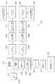
図1は、実施形態による例示的な保管および取り出しシステム100を概略的に示す。開示される実施形態は、図面に示されている実施形態を参照して説明されるが、開示される実施形態は、多くの代替的な形態で実施され得る。さらに、任意の適切なサイズ、形状またはタイプの要素または材料が使用され得る。FIG. 1 illustrates a schematic diagram of an exemplary storage and
実施形態によれば、保管および取り出しシステム100は、例えば、小売店から受けたケースユニットに関する注文を満たすために、小売流通センターまたは倉庫において動作してもよい(本明細書において使用されるケースユニットは、トレイ内、トート上もしくはパレット上に保管されていない品物、例えば収容されていない(uncontained)品物、またはトレイ内、トートまたはパレット上に保管されている品物を意味する)。ケースユニットは、パレットから引き取られるかまたはパレット上に配置されるよう適合された品物のケース(スープ缶のケース、シリアルの箱等)または個別の品物を含んでもよいことに留意する。実施形態によれば、配送ケースまたはケースユニット(例えば、カートン、樽、箱、クレート(crates)、つぼ(jug)、トート、パレットまたはケースユニットを保持するのに適切な任意の他のデバイス等)は、サイズが変更可能であってもよく、配送において品物を保持するために使用されてもよく、配送のためにパレットに積載可能であってもよい。例えば、ケースユニットの一団またはパレットが保管および取り出しシステムに到着した際、パレットの各々の内容物は、同一であってもよく(例えば、パレットの各々が所定数の同一の品物を保持する1つのパレットがスープを保持し、別のパレットがシリアルを保持する)、パレットが保管および取り出しシステムから離れる際に、パレットが、適切な数でかつ組み合わされた異なった品物を含んでいてもよい(例えば、パレットの各々が、様々なタイプの品物を保持してもよい-1つのパレットがスープおよびシリアルの組み合わせを保持する)。本明細書に記載されている保管および取り出しシステムは、ケースユニットが保管されかつ取り出される任意の環境に適用されてもよいことが理解されるべきである。According to an embodiment, the storage and
保管および取り出しシステム100は、例えば、既存の倉庫構造に導入されるように構成されてもよいし、新しい倉庫構造に適合するようにされてもよい。実施形態において、保管および取り出しシステムは、インフィードおよびアウトフィード搬送ステーション170、160、マルチレベル垂直コンベヤ150A、150B、自律搬送車両またはロボット(本明細書において「ボット」と称する)ステーション140A、140B、保管構造物130、および複数のボット110を含んでもよい。保管および取り出しシステムの適切な例は、「STORAGE AND RETRIEVAL SYSTEM」と題され2010年4月9日に出願された米国特許出願第12/757,220号明細書、「STORAGE AND RETRIEVAL SYSTEM」と題され2010年4月9日に出願された米国特許出願第12/757,381号明細書、「WAREHOUSING SCALABLE STORAGE STRUCTURE」と題され2010年12月15日に出願された、代理人整理番号が1127P014551-US(-#1)の米国仮特許出願(第61/423,340号明細書)(現在は、2011年12月15日に出願された、代理人整理番号が1127P014551-US(PAR)の米国特許出願第13/326,674号明細書)に見ることができ、これらの出願の開示内容は、その全体を参照することによって本明細書に含まれている。インフィード搬送ステーション170およびアウトフィード搬送ステーション160は、保管構造物130の1つまたは2つ以上の垂直に積層されたレベルへ、かつその1つまたは2つ以上の垂直に積層されたレベルから、ケースユニットを双方向に搬送するために、それらの各々のマルチレベル垂直コンベヤ150A、150Bと共に動作してもよい。本明細書においては、マルチレベル垂直コンベヤ150が、専用の入庫(inbound)またはインフィードコンベヤ150Aおよび出庫(outbound)またはアウトフィードコンベヤ150Bとして説明されているが、コンベヤ150Aおよび150Bの各々は、保管および取り出しシステムのケースユニット/品物の入庫および出庫搬送の両方に使用されてもよい。マルチレベル垂直コンベヤ150は、保管および取り出しシステムのレベル間でケースユニットを搬送する任意の適切なリフト装置であってもよい。マルチレベル垂直コンベヤの非限定的な適切な例のいくつかは、例えば、「LIFT INTERFACE FOR STORAGE AND RETRIEVAL SYSTEMS」と題され2010年12月15日に出願された、代理人整理番号が1127P014525-US(PAR)の米国仮特許出願、および「LIFT INTERFACE FOR STORAGE AND RETRIEVAL SYSTEMS」と題され2010年4月9日に出願された米国特許出願第12/757,354号明細書(これらの出願の開示内容は、その全体を参照することによって本明細書に含まれている)、ならびに「STORAGE AND RETRIEVAL SYSTEM」と題された米国特許出願第12/757,220号明細書(すでに参照により本明細書に含まれている)に見られ得る。例えば、マルチレベル垂直コンベヤ150A、150Bは、保管および取り出しシステム100の所定のレベルにケースユニットを搬送するために、任意の適切な数の支持棚を有していてもよい。本明細書においては、マルチレベル垂直コンベヤが記載されているが、他の態様においてコンベヤは、任意の適切な搬送経路の向きを有する任意の適切なコンベヤまたは搬送/取り出し装置であってもよいことに留意する。実施形態において、ボット110とマルチレベル垂直コンベヤとの間のケースユニットの搬送は、ボット110とコンベヤとの間の任意の適切なインタフェースを通した、任意の適切な方法であってよい。また、ケースユニットは、例えば、「STORAGE AND RETRIEVAL SYSTEM」と題された米国特許出願第12/757,220号明細書(すでに参照により含まれている)に記載されるように、ボット110とマルチレベル垂直コンベヤ150A、150Bとの間で間接的に搬送されてもよい。ボット110とマルチレベル垂直コンベヤとの間のケースユニットの搬送は、任意の適切な方法であってよいことに留意する。The storage and
理解されるように、保管および取り出しシステム100は、例えば、保管および取り出しシステム100の積層されたレベルの各々のレベルのボット110によってアクセス可能な複数のインフィードおよびアウトフィードマルチレベル垂直コンベヤ150A、150Bを含んでもよく、それによって、1つまたは2つ以上のケースユニットがマルチレベル垂直コンベヤ150A、150Bから各々のレベルの保管スペースの各々へ、および保管スペースの各々から各々のレベルのマルチレベル垂直コンベヤ150A、150Bの任意の1つへ搬送されることが可能となる。ボット110は、保管ラック600(図3)上の保管スペースとマルチレベル垂直コンベヤとの間で、1回の取り出しによって(例えば、保管スペースとマルチレベル垂直コンベヤとの間でほぼ直接)ケースユニットを搬送するよう構成されてもよい。他の例として、指定されたボット110が、マルチレベル垂直コンベヤの棚から、ケースユニットを取り出し、ケースユニットを保管構造物130の所定の保管エリアに搬送し、ケースユニットを所定の保管エリア内に配置する(その逆も同様である)。As will be appreciated, the storage and
ボット110は、保管構造物130の1つまたは2つ以上のレベルの取り出し台(picking stock)内に、上述の小売商品等のケースユニットを置いて、注文された品物を、例えば店舗または他の適切な場所等に配送するために注文された品物を選択的に取り出すように構成されてもよい。上述のように、実施形態においてボット110は、例えば、ボットのフレームと関連するボットの搬送アーム110A(図4A~4E)の延伸によって、などの任意の適切な方法で、マルチレベル垂直コンベヤ150A、150Bと連動してもよい。またボットは、他の任意の適切な方法で、マルチレベル垂直コンベヤと連動してもよい。ボットの適切な例は、「AUTONOMOUS TRANSPORTS FOR STORAGE AND RETRIEVAL SYSTEMS」と題され2010年4月9日に出願された米国特許出願第12/757,312号明細書、「BOT PAYLOAD ALIGNMENT AND SENSING」と題され2010年12月15日に出願された、代理人整理番号が1127P014263-US(-#1)の米国仮特許出願(第61/423,220号明細書)(現在は、2011年12月15日に出願された、代理人整理番号が1127P014263-US(PAR)の第13/327,040号明細書)、「AUTOMATED BOT WITH TRANSFER ARM」と題され2010年12月15日に出願された、代理人整理番号が1127P014264-US(-#1)の米国仮特許出願(第61/423,365号明細書)(現在は、2011年12月15日に出願された、代理人整理番号が1127P014264-US(PAR)の第13/326,952号明細書)、「AUTOMATED BOT TRANSFER ARM DRIVE SYSTEM」と題され2010年12月15日に出願された、代理人整理番号が1127P014265-US(-#1)の米国仮特許出願(第61/423,388号明細書)(現在は、2011年12月15日に出願された、代理人整理番号が1127P014265-US(PAR)の第13/326,993号明細書)、「BOT HAVING HIGH SPEED STABILITY」と題され2010年12月15日に出願された、代理人整理番号が1127P014266-US(-#1)の米国仮特許出願(第61/423,359号明細書)(現在は、2011年12月15日に出願された、代理人整理番号が1127P014265-US(PAR)の第13/326,993号明細書)、および「BOT POSITION SENSING」と題され2010年12月15日に出願された、代理人整理番号が1127P014267-US(-#1)の米国仮特許出願(第61/423,206号明細書)(現在は、2011年12月15日に出願された、代理人整理番号が1127P014267-US(PAR)の第13/327,035号明細書)に記載されており、これらの出願の開示内容は、その全体を参照することによって本明細書に含まれている。The
保管構造物130は、保管ラックモジュール600の複数のレベルを含んでいてもよく(図3)、各々のレベルが、保管スペースのアレイ(複数のレベルに整列され、かつ、各々のレベルにおいて複数の列に整列されている)、保管スペースの列の間に形成されている取り出し通路130A、および搬送デッキ130Bを含んでいてもよい。実施形態において、取り出し通路130Aおよび搬送デッキ130Bは、ボット110が、ケースユニットを取り出し台内に配置するために保管構造物130の各レベルを行き来し、注文されたケースユニットを取り出すことを可能にするように配置されてもよい。理解されるように、保管および取り出しシステムは、保管スペースへのランダムなアクセスを可能にするように構成されてもよい。例えば、保管構造物130の全ての保管スペースは、ケースユニットを保管構造物130から取り出す/保管構造物130へ置く際に、十分なサイズの任意の保管スペースが品物の保管に使用され得るようにどの保管スペースが使用されるべきかを決定するときに、ほぼ同等に扱われてもよい。例示的な実施形態の保管構造物130は、保管構造物の垂直方向または水平方向のアレイの分割無しに構成されてもよい。例えば、任意のボット110が保管スペースの各々にアクセスでき、かつ、任意のマルチレベル垂直コンベヤ150A、150Bが任意のレベルの任意の保管スペースからケースユニットを受け取ることができるように、マルチレベル垂直コンベヤ150A、150Bの各々が保管構造物130内の全ての保管スペース(例えば、保管スペースのアレイ)で共通であってもよく、それにより、保管スペースのアレイ内の複数のレベルが実質的に単一のレベルとして振る舞ってもよい(例えば、垂直方向の分割無し)。マルチレベル垂直コンベヤ150A、150Bは、保管構造物130の任意のレベルの任意の保管スペースからケースユニットを受け取ることも可能である(例えば、水平方向の分割無し)。保管および取り出しシステムは、各マルチレベル垂直コンベヤが保管スペースのアレイの所定領域を受け持つように構成されてもよいことに留意する。保管および取り出しシステムの適切な例示的構成は、例えば、「STORAGE AND RETRIEVAL SYSTEM」と題され2010年4月9日に出願された米国特許出願第12/757,381号明細書に見られ、この開示内容は、その全体を参照することによって本明細書に含まれている。The
保管構造物130は、例えば、「AUTONOMOUS TRANSPORT VEHICLE CHARGING SYSTEM」と題され2010年12月15日に出願された、代理人整理番号が1127P014517-US(-#1)の米国仮特許出願(第61/423,402号明細書)(現在は、2011年12月15日に出願された、代理人整理番号が1127P014517-US(PAR)の第13/326,823号明細書)に記載されるような、ボット110の電力貯蔵装置を充電する充電ステーション290を含んでもよく、この出願の開示内容は、その全体を参照することによって本明細書に含まれている。例えば、充電ステーション290は、ボット110が、例えば、充電されている間に、マルチレベル垂直コンベヤ150A、150Bに、およびマルチレベル垂直コンベヤ150A、150Bから、品物をほぼ同時に搬送できるように、例えば搬送デッキ130Bのボットステーション140(図3)の搬送領域に配置されてもよい。The
保管および取り出しシステム100のボット110および他の適切な特徴は、例えば、任意の適切なネットワーク180等を介して、例えば、1つまたは2つ以上の中央システム制御コンピュータ(例えば、制御サーバ)120によって制御されてもよい。ネットワーク180は、任意の適切なタイプおよび/または数の通信プロトコルを用いた有線ネットワーク、無線ネットワーク、または無線および有線ネットワークの組み合わせであってもよい。実施形態において、システム制御サーバ120は、保管および取り出しシステム100の全ての動作を管理および調整するように構成されてもよく、かつ、例えば、倉庫管理システム125と連動して全体として倉庫設備を管理するように構成されてもよいことに留意する。制御サーバ120は、例えば、「CONTROL SYSTEM FOR STORAGE AND RETRIEVAL SYSTEMS」と題され2010年4月9日に出願された米国特許出願第12/757,337号明細書に記載されるものと実質的に同様のものでよく、この出願の開示内容は、その全体を参照することによって本明細書に含まれている。The
図2を参照すると、保管および取り出しシステム100の例示の構成が示されている。保管および取り出しシステムの他の適切な例示の構成は、例えば、「STORAGE AND RETRIEVAL SYSTEM」と題され2010年4月9日に出願された米国特許出願第12/757,381号明細書、および「WAREHOUSING SCALABLE STORAGE STRUCTURE」と題され2010年12月15日に出願された、代理人整理番号が1127P014551-US(-#1)の米国仮特許出願(第61/423,340号明細書)(現在は、2011年12月15日に出願された、代理人整理番号が1127P014551-US(PAR)の米国特許出願第13/326,674号明細書)に見られ、これらの出願の開示内容は、その全体を参照することによって本明細書に含まれている。実施形態において、保管および取り出しシステムは任意の適切な構成を有していてよいことを理解されたい。図2からわかるように、保管および取り出しシステム200は、単に例示目的で、システム200の一方の側のみが搬送セクションまたはデッキ130Bを有している、シングルエンド取り出し構造として構成されている。シングルエンド取り出し構造は、例えば、建物の一方の側のみに配される積み込みドックを有する建物または他の建造物において使用されてもよい。この実施形態において、保管および取り出しシステム200は、任意の適切な保管場所/取り出し通路130Aと任意の適切なマルチレベル垂直コンベヤ150A、150Bとの間で品物を搬送するために、ボット110が、そのボット110が配されている保管構造物130のあるレベル全体を行き来することを可能にする1つまたは2つ以上の搬送デッキ130Bおよび複数の取り出し通路130Aを含んでいる。マルチレベル垂直コンベヤ150A、150Bは、搬入ワークステーション(input workstation)210を通して、保管および取り出しシステム200内へのケースユニットの搬送を提供し、また搬出ワークステーション(output workstation)220を通して、保管および取り出しシステム200からのケースユニットの搬送を提供する。実施形態において、保管および取り出しシステム200は、並んで配されている第1および第2の保管セクション230A、230Bを含み、各々のセクションの取り出し通路は、互いにほぼ平行であり、同一の方向を向いている(例えば、搬送デッキ130Bの方を)。しかしながら、実施形態において保管および取り出しシステムは、任意の適切な構成で互いに対して配置される任意の数の保管セクションを有していてもよい。With reference to Figure 2, an exemplary configuration of the storage and
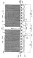
次に図3を参照すると、保管および取り出しシステム100の1つのレベル100Lの部分が示されている。理解されるように、実質的に同様のレベルが、レベル100Lの上部および/または下部に配置されて、上述のような垂直に積層された保管レベルのアレイを形成してもよい。実施形態において各レベル100Lは、搬送デッキ130Bおよび1つまたは2つ以上の取り出し通路130A1~130A7を有していてもよい。保管ラック600は各取り出し通路130A1~130A7のどちら側に置かれてもよく、ケースユニット101は各取り出し通路の両側で保管され得る。Referring now to FIG. 3, a portion of one
搬送デッキ130Bは、搬送デッキ130B上にある間、通常は物理的に拘束されないボット110の移動を可能にするように構成されてもよい。例えば、搬送デッキ130Bは、ボット110が行き来する1つまたは2つ以上の移動経路または移動レーンを形成する、任意の適切な数の移動ガイド線130L1~130L4および任意の適切な数の分岐(shunt)またはバイパスガイド線130S1~130S7を有していてもよい。例えば、ガイド線130L1、130L2は第1の方向への移動を可能にし、ガイド線130L3、130L4は第1の方向とほぼ反対の第2の方向への移動を可能にする。各ガイド線130L1~130L4に沿った移動の方向は、通常は単一の方向であるが、ガイド線は、例えば適切なボットの通行管理と組み合わされて、以下に記載するような、ガイド線130L1~130L4に沿うボット110の制限された双方向への移動を可能にしてもよいということに留意する。実施形態においてボットの通行は、例えばボット同士の通信を介して管理されてもよく、および/または、通行は、例えば制御サーバ120または保管および取り出しシステムの他の適切なコントローラを介したボットの位置追跡および管理によって管理されてもよい。適切なボットの通行管理の例は、例えば、「CONTROL SYSTEM FOR STORAGE AND RETRIEVAL SYSTEMS」と題され2010年4月9日に出願された米国特許出願第12/257,337号明細書に見られ、この出願の開示内容は、その全体を参照することによって本明細書に含まれている。The
分岐ガイド線130A1~130S7は、ボット110がガイド線130L1~130L4の間で双方向に切り替わり、取り出し通路130A1~130A7に入ることを可能にするために、ガイド線130L1~130L4を横断して搬送デッキに配置されてもよい。分岐ガイド線130S1~130S7は、移動ガイド線130L1~130L4を実質的に横切る向きに合わされている。分岐ガイド線130S1~130S7は、ボットが、移動ガイド線130L1~130L4の全長を行き来することなしに、例えば、取り出し通路130Aまたはボットステーション140にアクセスすることを可能にしてもよい。実施形態において、分岐ガイド線は、取り出し通路130A1~130A7または保管および取り出しシステムの他の任意の適切な進入または退出位置と整列されてもよく、これはボットが移動ガイド線130L1~130L4のいずれか1つに沿って移動する間に対応する取り出し通路に入ることを可能にする。分岐ガイド線130S1~130S7は、搬送デッキ130Bの端部に配置されてもよく、搬送デッキ130Bの他の任意の適切な位置に配置されてもよいことに留意する。分岐ガイド線130A1~130S7は、保管および取り出しシステムの構造を通してボット110の位置を追跡し、移動ガイド線130L1~130L4に沿った移動を監視するために用いられてもよい。例えば、分岐ガイド線130A1~130S7の位置は、制御サーバ120によってまたは制御サーバ120内でアクセス可能なメモリに記録されてもよく、ボット110は、ボットの位置、および、1つまたは2つ以上のボットが、例えば移動ガイド線130L1~130L4に沿って移動しているかどうかが制御サーバによって決定され得るように、分岐ガイド線130A1~130S7に対応する信号を検出し、これを制御サーバ120に送るように構成されてもよい。The branching guide lines 130A1-130S7 may be positioned on the transport deck across the guide lines 130L1-130L4 to allow the
ボットステーションガイド線130C1~130C3も、ボット110が、各マルチレベル垂直コンベヤ150と連動するために、ガイド線130L1~130L4のいずれかからボットステーション140に入ることを可能にするために、搬送デッキ130Bに設けられてもよい。コンベヤアクセスガイド線130C1~130C3は、分岐ガイド線130S1~130S2と実質的に同様のものでもよい。この例においてボットステーション140の入口/出口ガイド線130C1、130C2は、どの分岐130S1~130S7とも整列されずに示されているが、他の実施形態において、ボットステーション150の入口/出口ガイド線は、分岐(例えば、ガイド線130S7参照)と実質的に整列されてもよく、これにより移動コースが許す限り、ボット110は取り出し通路からボットステーションへ直接移動することができ、その逆も同様である。搬送デッキ130Bおよびボットステーション140の実施形態は、本明細書ではライン追従に関して記載されているが、搬送デッキ130Bおよびボットステーション140は、ボットが任意の適切なレールシステムによって誘導されるように構成されてもよいことに留意する。The bot station guide lines 130C1-130C3 may also be provided on the
図4A~4Eを参照すると、例示的なボット110が示されている。実施形態においてボット110は、第1端部1500および第2端部1501を有する長手方向に延伸したフレーム110FRを含んでおり、長手方向の軸(例えば、Y軸)110Xは、第1端部1500から第2端部1501に延伸している。少なくとも1つの駆動セクション110Dは、搬送デッキ130Bおよび取り出し通路130Aに沿ってボット110を駆動する(図1)ために、任意の適切な方法で第1および/または第2端部1500、1501の1つに連結されてもよい。駆動装置110Dは、駆動ホイール、トラック(tracks)、または、搬送デッキ130B、および取り出し通路130Aに沿うボットの移動をもたらす他の任意の適切な駆動機構を含んでいてもよい。ボット110の他の端部1500、1501は、キャスタホイール、固定ホイール、操舵可能ホイール等の任意の適切な支持体、およびボット110が搬送デッキ130Bおよび取り出し通路130Aに沿って移動するときにボット110を可動に支持する同様の機構を有していてもよい。ボット110は、ボット110の動作、および/または、ボット110と制御サーバ120(図1)との間の通信をもたらすために、任意の適切なコントローラ1220(図1)を有していてもよい。理解されるように、図示されているボットの構成は単に例示的なものであり、ボットは、本明細書に記載されるようなボット110に関するケースユニットの検出および位置決めを実行するために、任意の適切な構成を有していてもよい。4A-4E, an
ボット110のフレーム110FRは、ケースユニットまたは他の任意の適切な積載物を保持するように構成される、積荷台1510または他の適切な保持構造物を形成してもよい。積荷台1510は、保管および取り出しシステム100内に搬送されるか、またはそこから取り除かれ得る任意のケースユニット(または、ピックフェース(pickface)がボット110によって取り出され運ばれる1つまたは2つ以上のケースユニットである場合にはピックフェース)を受け容れる(例えば、保持する)のに適切なサイズにされてもよい。例えば実施形態において、積荷台1510は予測されるピックのサイズよりも大きくてもよい(すなわち、例えば保管セクション230A、230Bの保管棚、またはマルチレベル垂直コンベヤ等の保管および取り出しシステムの他の任意の適切な構成要素から、ボットが取り出すと予測されるピックフェースよりも大きい)。The frame 110FR of the
フェンス1510Fまたは他の任意の適切な保持デバイスは、積荷台1510の側面開口部に配置されてもよい。1つの例示的な実施形態において、フェンス1510Fは、締め具、または溶接等を用いて任意の適切な方法でフレーム110FRに取り付けられてもよい。実施形態においてフェンス1510Fは、フレーム110FRの一部を形成していてもよく、またフレーム110FRを備える単一の構造体であってもよい。フェンスは、阻止部材1510FMの間に配置されるスロット1510FSを含んでいてもよい。スロット1510FSは、フィンガー110Fが、例えば、ケースユニットの下部の保管棚内に延伸され得るように、ボットアーム110Aのフィンガー110Fが実質的に下げられた位置でフェンス1510Fを通って延伸することを可能にするように構成されてもよい。フェンス1510Fは、積荷台1510の上部に延伸してバリアを形成するように構成されてもよく、このバリアは、一度ケースユニットが積荷台1510上に配置されると、ケースユニットが積荷台1510から抜け出ることを実質的に防ぐ。この実施形態において、スロット1510FSの数はフィンガー110Fの数と等しいが、代替的な実施形態において、フェンス1510Fは、2つ以上のフィンガー110Fが単一のスロットを通過するように構成されてもよい(例えば、スロットの数はフィンガーの数よりも少ない)。フェンスは、ケースユニットがボット110により運ばれるときに、ケースユニットが積載領域から抜け出ることを防ぐための、任意の適切な構成を有していてもよいことに留意する。例えば、フェンスは可動であってもよく、このため、フェンスが延伸された形態にあるときに、ケースユニットが積載領域から抜け出ることをフェンスが防ぐように、阻止部材が後退可能である。A
積荷台1510は、ケースユニットがボット110によって運ばれるときにケースユニットを支持するために、任意の適切な積載物支持体を含んでいてもよい。例示のみを目的として、積載物支持体は、ローラ1510Rを含んでいてもよく、各ローラ1510Rの回転軸は、ボット110の長手方向の軸110Xに対してほぼ横に(または横方向に)配置されている。積載物支持体は、ベルト、ボールベアリングまたは他の任意の適切な支持体であってもよいことに留意する。ローラ1510R(または他の適切な積載物支持体)は、代替的な態様においてはボット110の片持ち梁状のフィンガー110Fと相互に配置されてもよい。実施形態においてローラ1510Rおよびフィンガー110Fは、互いに対して任意の適切な態様にて配置されてもよい。一例において、積載物支持体は、例えば、「BOT PAYLOAD ALIGNMENT AND SENSING」と題され2010年12月15日に出願された、代理人整理番号が1127P014263-US(-#1)の米国仮特許出願(第61/423,220号明細書)(現在は、2011年12月15日に出願された、代理人整理番号が1127P014263-US(PAR)の米国特許出願第13/327,040号明細書)に記載されるように、積載領域の積載物の位置を揃えるために任意の適切な方法で駆動されてもよく、これらの出願の開示内容は、その全体を参照することによって本明細書に含まれている。The
ボットアーム110Aのフィンガー110Fは、ボットの長手方向の軸110Xに対して、矢印1550の方向で横方向に延伸する。フィンガー110Fはさらに、矢印1673の方向に(例えば、フィンガーの延伸および後退方向1550に略直交する方向に)動作することが可能である。フィンガーは、フェンス1510Fを越えてボット110の積荷台1510内/外へピックフェースを持ち上げる、任意の適切な駆動装置によって駆動されてもよい。フィンガー110Fは、保管棚600およびマルチレベル垂直コンベヤ150へ、またそれらからケースユニットを搬送するために、保管棚600およびマルチレベル垂直コンベヤ150の棚上の薄く細長い形状の支持体の間に適合するように配置されてもよい。ボットアーム110Aは、ケースユニットをボット110へまたはボット110から搬送するために、任意の適切な構成を有していてもよいことに留意する。実施形態においてボット110のアーム110Aは、ボット110の1つの側面への延伸用に構成されてもよい(例えば、ピックフェンス1510Fが配置されるボットの取り出し側であって、ケースユニットは、ボットへまたはボットからの搬送中にピックフェンスを越えて持ち上げられてもよく、ピックフェンスは搬送の間ケースユニットをボット110上で保持するために用いられてもよい)。アーム110Aは、ボットの両方の側面への延伸のために構成されてもよいことに留意する。アーム110Aがボット110の1つの側に延伸される場合、ボット110の移動方向に対するボットの方向付け(例えば、前端が先頭か、または前端が後置か)は、アーム110Aの延伸方向が、ケースユニットが取り出される、または搬送される取り出し通路130A1~130A7またはボットステーションの側に位置するように考慮される。The
ケースユニット接触部材1530は、少なくとも部分的に積載領域内に可動に配置されてもよい。ケースユニット接触部材1530は、任意の適切な駆動装置によって、矢印1550の方向に横方向に駆動されてもよい。この例示的な実施形態においては、ケースユニット接触部材1530およびフィンガー110Fの両方が、矢印1550の方向に横方向に移動するように構成されている。ケースユニット接触部材1530は、レール1530R(図7Aおよび7B)に沿って移動するように構成されてもよい。レールは、少なくともケースユニット接触部材1530の移動を導くために、任意の適切な態様にてフレーム110FRに取り付けられてもよい。実施形態において、ケースユニット接触部材1530の移動は、任意の適切な方法で導かれてもよい。例示のみを目的として、図7Aおよび7Bを参照すると、ケースユニット接触部材1530は、ケースユニット接触部材1530をレール1530Rに可動に連結するために、スライド部材1530Dを有していてもよい。実施形態においてケースユニット接触部材1530は、積荷台1510上に置かれたケースユニットと係合するために、フィンガー110Fから独立して矢印1550の方向に移動可能であってもよい。フィンガー110Fは、フィンガー110Fがケースユニット接触部材の駆動システムを用いて延伸されるように、任意の適切な態様にてケースユニット接触部材1530に分離可能に連結されてもよい。ボット搬送アーム、フィンガーおよび搬送アームの駆動システムの適切な例は、「AUTOMATED BOT TRANSFER ARM DRIVE SYSTEM」と題され2010年12月15日に出願された、代理人整理番号が112P014265-US(-#1)の米国仮特許出願(第61/423,388号明細書)(現在は、2011年12月15日に出願された、代理人整理番号が112P014265-US(PAR)の第13/326,993号明細書)および「AUTOMATED BOT WITH TRANSFER ARM」と題され2010年12月15日に出願された、代理人整理番号が1127P014264-US(-#1)の米国仮特許出願(第61/423,365号明細書)(現在は、2011年12月15日に出願された、代理人整理番号が1127P014264-US(PAR)の第13/326,952号明細書)に見られ、これらはすでに参照により本明細書に含まれている。The case
上述のように、ボット110は、搬送デッキ130Bおよび複数の取り出し通路130Aを行き来するように構成されている。ボット110が1つまたは複数の搬送デッキ130Bに沿って移動する速度は、ボットが取り出し通路で移動する速度よりも速くてもよい。実施形態においてボット110は、任意の適切な速度で搬送デッキおよび取り出し通路内を移動してもよい。搬送デッキ130B上では、ボット110は約10m/sまでの速度で移動することを期待されてもよく、より早い速度が求められてもよい。例えば、すでに参照により本明細書に含まれている米国特許出願第12/757,312号明細書に記載されているように、ボット110は、取り出し通路130A内の移動中に軌道やレールなどの機械的なガイドの束縛によって誘導されてもよいが、ボットは、拘束されないまたは制限されない態様で(例えば、実質的に軌道やレールなどの機械的な誘導なしに)搬送デッキ130Bに沿って移動してもよい。ボットは、例えば、1つまたは複数の搬送デッキ130Bおよび複数の取り出し通路130Aの1つまたは2つ以上に沿ってボットを誘導するボットコントローラ1220にフィードバックを提供するために、1つまたは2つ以上のライン追従センサ380A、380B、および、1つまたは2つ以上のホイールエンコーダ381、382などの任意の適切なセンサを含んでいてもよい。実施形態においてボットコントローラ1220は、ボット110に載せられて配置されてもよいし、および/またはボット110から離れて配置されてもよいが、例えば、ボット110と双方向通信で配置されてもよい。一例において制御サーバ120は、少なくとも部分的に、遠隔に配置されたボットコントローラとして作動してもよい。As described above, the
上述のように、ボット110は、少なくとも2つの、独立して駆動される駆動ホイール1211、1212と、少なくとも1つの旋回可能な(操舵されず、すなわち、独立した操舵入力を備えない)ホイールまたはキャスタ1261、1262を含んでいてもよい。別の態様において、駆動ホイール1211、1212は、共通の原動機および任意の適切な方法で一緒に駆動されるホイールに所望のヨー入力についての差動トルクを与えるか、または生じさせることができる伝動装置によって駆動されてもよい。キャスタ1261、1262および駆動ホイール1211、1212は、ボット110のほぼ対向する長手方向(例えば、前後)の端に配置されており、ホイールは、実質的にボットの四隅のそれぞれに配置されていることに留意する。このキャスタホイール/駆動ホイールの構成は、ボットの高速安定性および制御の容易さの向上を提供し得る。各駆動ホイール1211、1212は、本明細書に記載される方法でボットコントローラ1220によって制御される、自身の原動機383、384をそれぞれ有していてもよい。以下でより詳細に記載するように、キャスタ1261、1262は、例えば、搬送デッキ130Bに沿った、実質的に高速でのボットの移動の間のボット110の安定した移動を可能にするために、選択的に固定されてもよい。低速移動の間には、キャスタ1261、1262は固定されていなくてもよく、これによりボット110は、例えば、ボット110の前部または後部のいずれかがボット移動方向に向いて、取り出し通路および/またはマルチレベル垂直コンベヤインターフェースステーションに入り得るということに留意し、これは例えば、「AUTONOMOUS TRANSPORT VEHICLE」と題され2010年12月15日に出願された、代理人整理番号が1127P014258-US(-#1)の米国仮特許出願(第61/423,409号明細書)(現在は、2011年12月15日に出願された、代理人整理番号が1127P014258-US(PAR)の米国特許出願第13/326,423号明細書)に記載されており、この出願の開示内容は、その全体を参照することによって本明細書に含まれている。搬送デッキに沿ったボット110の操舵は、それぞれ独立した制御型原動機383、384を通して、駆動ホイール1211、1212に差動トルクを付加することによってもたらされてもよい。差動トルクTは、駆動ホイールのそれぞれが異なる速度で回転する(例えば、複数の回転)という結果をもたらしてもよい。各ホイールの異なる回転速度は、ボット110に向きを変えさせたり、曲がらせたりすることができる。As described above, the
各ボット110は、ガイドおよび位置決めシステムの組み合わせを用いてもよく、(例えば、搬送デッキ130B上で)例えばライン追従と、(例えば、取り出し通路内で)レールの誘導とを用いてもよい。保管および取り出しシステムは、例えば取り出し通路内の、構造上確定的な、または拘束的な誘導システムと、例えば搬送デッキの、非拘束的な誘導システムとの間を、ボットが移行することを可能にするように構成されてもよい。誘導システム間の移行は、ボットの方向付け(例えば、前端が移動方向の先頭か、または前端が移動方向の後方か)の変化を含んでいてもよい。各ボット110は、ボット110のフレーム110FRに取り付けられる任意の適切なガイドを含んでいてもよく、ガイドは、ボット110と、例えば保管棚600との間でケースユニット101を搬送するために、ボット110の搬送アーム110Aの正確かつ所定の到達範囲を可能にする目的で、拘束的な誘導システムと所定の繰り返し可能な態様で係合するように構成されている。またガイドは、少なくとも部分的に、非拘束的な誘導システムと拘束的な誘導システムとの間の移行を容易にしてもよい。Each
ボット110の一般的な移動方向は、前端1500が移動方向を先導し、キャスタホイール1261、1262が、すでに参照により本明細書に含まれている、「BOT HAVING HIGH SPEED STABILITY」と題された、代理人整理番号が1127P014266-US(PAR)の米国仮特許出願に記載されるように固定されている状態であってもよく、結果としてボットは実質的に高速で安定して移動できることに留意する。低速の場合、ボットは、前端が前にある状態で、または前端が後ろにある状態で移動してもよい。ボットは、ボット上に載せられるか、またはボットから離れて配置されている任意の適切な制御システムによって、固定されていないキャスタと共に駆動されるようにも構成され得る。It is noted that the general direction of travel of the
ボット110は、例えば、すでに参照により本明細書に含まれている、「AUTOMATED TRANSPORT VEHICLE CHARGING SYSTEM」と題され、代理人整理番号が1127P014157-US(PAR)の米国仮特許出願、および「AUTONOMOUS TRANSPORTS FOR STORAGE AND RETRIEVAL SYSTEMS」と題された米国特許出願第12/757,312号明細書に記載されるように、ガイド線130L1~130L4、130S1~130S7、130C1~130C3を感知する任意の適切な数のセンサ110Sを有していてもよい。ボットは、場合によっては、ガイド線を使用することなく、例えば単なる例示目的であるが、デッドレコニング、状態推測、ならびに、ジャイロスコープおよび加速度計の利用などの任意の制御手段を通して駆動し得ることに留意する。ボット110は、以下に記載するように、取り出し通路130A1~130A7内へ、およびこれらに沿ってボット110を誘導するために、任意の数の適切な誘導ホイール351~354を有していてもよい。適切な誘導ホイール/レールの相互作用は、例えば、米国特許出願第12/757,312号明細書、米国特許出願第12/757,381号明細書および米国特許第12/757,220号明細書に記載されており、これらの出願は、すでに参照により含まれている。誘導ホイール351~354は、任意の適切な態様で任意の適切なガイドと相互作用してもよいことに留意する。誘導ホイールが図面に示されているが、別の態様においてボットは、例えば、二次元の枢軸のずれ(pivot offset)および一次元の枢軸のずれを有する任意の適切な誘導部材を含んでいてもよいことを理解されたい。さらに、誘導部材の1つまたは2つ以上は、他の誘導部材と異なるばね定数を有していてもよいことにも留意する。The
搬送デッキに沿ったボットの移動の一例として、図4Eおよび6を参照すると、例えば、ガイド線395に沿ったボットの直線移動(例えば、1自由度)の間、駆動ホイール1211、1212の両方はほぼ同一の速度/角速度で回転する。ボットの移動方向が、任意の適切な理由により補正されなければならない場合には、ボットのヨーイングを引き起こすために駆動ホイール1211、1212の1つが減速されてもよい。例えば、ボット110が矢印396の方向に回るか、または向きを変えるべき場合には、ボット110を矢印396の方向に向けるために、ボットコントローラ1220が駆動ホイール1211を駆動ホイール1212よりも低速で回転させてもよい。同様に、ボット110が矢印397の方向に回るか、または向きを変えるべき場合には、ボット110を矢印397の方向に向けるために、ボットコントローラ1220が駆動ホイール1212を駆動ホイール1211よりも低速で回転させてもよい。ボット110は、ガイド線395に沿った双方向の移動が可能であることに留意する。4E and 6 as an example of the movement of the bot along the transport deck, for example, during linear movement (e.g., one degree of freedom) of the bot along the
実施形態において、上述のように、ボットコントローラ1220に操舵のフィードバックを提供するために、例えば搬送デッキ130Bの表面に配置される線395などの、1つまたは2つ以上のガイド線391~395(図5に示すように設けられてもよい搬送デッキに沿ったボットの移動に対して横断する方向に、所定の間隔で搬送デッキ130B上に配置され得るガイド線391Aも含む)を検出するように構成される、1つまたは2つ以上のライン追従センサ380A、380Bを、ボット110が含んでいてもよい。1つまたは2つ以上のライン追従センサ380A、380Bは、ボット110の前部および後部に配置されてもよいし、ライン追従センサはボット上の任意の適切な位置に配置されてもよいことに留意する。ボットコントローラ1220は、1つまたは2つ以上のライン追従センサ380A、380Bまたはホイールエンコーダ381、382によって作り出された信号を受けとるように構成されてもよく、コントローラ1220はそこから、駆動ホイール1211、1212の各原動機383、384を駆動するのに適切なトルクの指示を決定する。In an embodiment, the
キャスタ1261、1262は、上述のように操舵されなくてもよいが、ボット110の操舵および制御を補助するように構成された方向または旋回固定具を有していてもよい。搬送デッキ130B上でのボットの略直線移動の間、キャスタ1261、1262は、ボット110が曲がるべき度合い(例えば、移動方向に対する補正を考慮して)が所定量(例えば、ボットの略直線移動の追従を補正するための所定の転回角度)を越えるか、または、移動速度が所定量を下回る場合を除いて、固定されてもよいことに留意する(例えば、キャスタホイール400の回転平面は、ボットの1自由度の軸110Xと実質的に並び、1自由度の軸110Xは、ボットの移動の直線方向と一致し得る)。キャスタは、キャスタが固定される場合よりも即応性の操舵をボットに提供するために、固定が解除されてもよく、その結果、ボットの移動方向に対するより迅速な補正がなされ得る。図5に示されるように、駆動ホイール1211、1212の反対側のボット100の端部での、キャスタ1261、1262の位置決めは、例えば、キャスタが配置されるボットの前部での、滑り角または横方向の移動量を増幅させるのに影響するということに留意する。滑り角または横方向の移動量は、駆動ホイール1211、1212での差動回転によって作り出されてもよい。滑り角は一般には小さく、ゆえに相応に小さい駆動ホイールでの差動回転によって作り出され、これは駆動ホイールの滑りを最小に見積もらせる(これは望ましくない)。キャスタホイールの滑りは、キャスタホイールが、例えば搬送デッキ130Bに沿って移動するときに、キャスタホイールの回転平面を実質的に横切る方向に「滑らされ」るように、キャスタの旋回固定具が固定され、差動トルクが駆動ホイールに加えられたときに生じてもよい。キャスタホイールの滑りの間、キャスタホイールはその回転を遅くしてもよいし、ほぼ回転を停止してもよいことに留意する。The
単に非制限的な例として、図4A、4C、4Eおよび6を参照すると、ボットは、線395に沿って搬送デッキ130B上を移動してもよく、ボットは米国特許出願第12/757,312号明細書(すでに参照により本明細書に含まれている)に記載される態様と実質的に同様の方法で取り出し通路130A1へ向きを変える。キャスタ1261、1262は、ボットが取り出し通路130A1に入るか、入りそうになるまで、安定した高速のボットの移動を可能にするために固定されてもよい。例えば、ボットが所定の移動速度を下回って減速すると、キャスタ1261、1262は固定を解除して、キャスタホイールの旋回を可能にしてもよい(例えば、ボットに運動の自由度2を与える)。ボットコントローラ1220は、転回の角度が所定の転回角を超えている場合に、ボットが曲がろうとしている(例えば、取り出し通路130A1へのほぼ90°の方向転換)と判断してもよい。キャスタ1261、1262は、ボットの略直線移動の追従を補正するために、転回角度が所定の転回角を超えているとの判断に基づいて固定を解除してもよい。ボットコントローラ1220は、いつキャスタ1261、1262の固定を解除するかを判断するときに、転回の角度およびボットの速度を考慮してもよい。コントローラ1220は、駆動ホイール1211、1212に差動トルクが加えられるのとほぼ同時に、キャスタ1262、1261の固定を解除させるように構成されてもよい。4A, 4C, 4E and 6, by way of non-limiting example only, the bot may travel on the
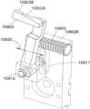
次に図5A~5Eを参照して、選択的に固定可能な旋回固定具を有する、旋回キャスタホイール1261、1262を説明する。キャスタは、キャスタ1262に関して記載されているが、キャスタ1261も実質的に同様のものであることに留意する。実施形態によれば、キャスタ1262は、フレーム412、ホイールヨーク410、ホイール400、第1固定部材440、第2固定部材450、アクチュエータ420およびバネ430を含んでいる。キャスタは、任意の適切な態様にて配置される任意の適切な構成要素を有していてもよいことに留意する。この例において、ホイール400は、任意の適切な態様にてヨーク410に回転可能に取り付けられている。第2固定部材450は、第2固定部材450およびヨーク410が一体のユニットを形成するように、ヨーク450に固定するように取り付けられてもよい。実施形態において第2固定部材は、一体的な構造でヨーク410と一体に形成されてもよい。ヨーク410(およびそこに取り付けられる第2固定部材450)は、(例えば、第2固定部材450、ヨーク410およびホイール400を含む)ヨークアセンブリが矢印499の方向に360°自由に回転され得るように、フレーム412に枢動可能に取り付けられていてもよい(図4Cも参照)。ヨークアセンブリの回転軸は、ボット110が移動する面、例えば、搬送デッキ130Bの面などに対して略垂直であることに留意する。第1固定部材440は、例えば、ヨーク450(およびホイール400)の旋回軸と略平行な旋回軸線を有する任意の適切な枢動軸441によって、フレーム412に枢動可能に取り付けられてよい。枢動軸441は、例えば、ショルダーボルトまたは他の任意の適切な軸および/または保持素子であってもよい。バネ430または他の任意の適切な弾性部材は、以下により詳細に記載するように、枢動軸441に対して第1固定部材440を付勢するために、フレーム430と第1固定部材440の一部との間に取り付けられてもよい。アクチュエータ420も、バネ430と対立する関係で第1固定部材440の一部と係合するためにフレーム412に取り付けられてもよい。アクチュエータ420は、例えば、アクチュエータ420の作動させるように構成されたボットコントローラ1220に適切に接続される、ソレノイド等の任意の適切なアクチュエータであってもよい。一態様においてアクチュエータ420は、水平に方向付けられてもよいが(例えば、水平に伸長および収縮するように配置される)が、他の態様において、アクチュエータは任意の適切な方向性を有していてもよい。キャスタ1262、1261の旋回固定具は、例えば、アクチュエータ420のパルス作動(例えば、アクチュエータのピストン420Pが、連続して、キャスタの旋回固定具を解除するために後退させられ、キャスタの旋回固定具を固定するために延伸させられるようにアクチュエータが制限された時間のみ作動されるように、所定の時間だけアクチュエータに電流が送られる)によって、迅速に固定および解除するように構成されてもよい。一例では、アクチュエータ420のパルス作動は、キャスタの旋回固定具を解除するために、約1秒または2秒の間アクチュエータを作動させてもよい。別の例において、アクチュエータのパルス作動は、約1秒未満の時間の間アクチュエータを作動させてもよい。さらに別の例では、アクチュエータのパルス作動は、約2秒よりも長い時間の間または任意の適切な時間の間アクチュエータを作動させてもよい。アクチュエータは、キャスタが、ピストン420Pが延伸されたときに解放され、ピストン420Pが後退させられたときに固定されるように構成されてもよい。理解されるように、一例において、任意の適切なセンサが設けられ、これはキャスタの旋回固定具のそれぞれが、いつ固定および/または非固定にされるかを感知するために、コントローラ1220と通信してもよい。別の例において、センサは、キャスタがいつ固定および/または非固定にされるかを感知するために設けられなくてもよい。5A-5E, swivel
この例示的な実施形態において、第1固定部材または固定棒/輪440は、実質的にくの字形状またはフック形状を有していてもよい。代替的な実施形態において、第1固定部材440は任意の適切な形状を有していてもよい。第1固定部材440は、第1固定部材が枢動軸ピン441に対して枢動することを可能にするために、枢動軸441を受け容れるように構成された枢動孔440Hを有していてもよい。第1固定部材440の第1の部分440Bは、枢動孔440Hから第1の方向に延伸してもよく、一方で、第1固定部材440の第2の部分440Cは、枢動孔440Hから第2の方向に延伸している。第1の方向および第2の方向は、任意の適切な角度(例えば、0~360度)で、互いに対して角度をつけられてもよい。この例において、第1の部分440Bは、第2固定部材450の、相反して成型された係合機構450S1、450S2と係合するように構成された突出部または他の固定機構440Lを含んでいる。第2の部分440Cは、第1固定部材440にバネ430を取り付けるために、取り付け機構440Sを含んでいてもよい。第2の部分440Cは、アクチュエータ係合面440Aを含んでいてもよい。この例において、第1固定部材の第1の部分440Bと第2の部分440Bとの比率は、第2の部分440Cに加えられる力が、第2固定部材450から固定機構440Lを解放するために、第1の部分440Bの正確な動きを引き起こすような比率であってもよい。例えば、第1固定部材440のレバー動作が、アクチュエータ420のストロークを、1つまたは2つ以上の係合機構450S1、450S2への、またはそれらから外れる突出部440Lの短い係合ストロークに変換し、これは結果として、旋回固定の実質的なオン/オフ制御を生じ、ボットが一定の速度(例えば、約10m/sまたはそれ以上)で移動している間、および/またはボットが任意の適切な速度で移動している間、旋回固定を確実に係合および解除し得る。In this exemplary embodiment, the first fixing member or fixing bar/
実施形態において、第2固定部材450は円板形状であるが、第2固定部材は任意の適切な形状を有していてもよい。第2固定部材は、1つまたは2つ以上の係合機構もしくはスロット450S1、450S2、または第1固定部材440の突出部440Lを受け容れ、相互に係合するように構成される他の保持機構を含んでいてもよく、また第2固定部材は、第1固定部材の係合機構または凹部を相互に係合する突出部を含んでいてもよい。実施形態において、第2固定部材は、キャスタホイール400が約0度および約180度で固定され得るように配置された2つのスロットを含んでいてもよく、この約0度および約180度の位置が固定されると、ホイール400の回転平面がボットの1自由度の軸110Xと実質的に合わさるように配置されている(これは、ボット110の直線移動の方向と一致してもよい)。実施形態において第2固定部材は、任意の角度でホイールを固定するために、任意の適切な態様で配置される任意の適切な数の固定機構を有していてもよい。In an embodiment, the second fixing
動作中、キャスタ1262を固定するために、アクチュエータは、第1固定部材440のアクチュエータ係合面440Aと実質的に接触しないように収縮させられてもよい(例えば、アクチュエータのピストン420Pまたは他の適切な係合機構が後退させられてもよい)。バネ430は、第1固定部材を引っ張るか、さもなければ付勢して、矢印495の方向で枢動軸441において回転させるように構成されており、それにより固定機構440Lは、第2固定部材450の側面450Sに対して実質的に押し付けられる。ヨークアセンブリが矢印499の方向に回転し、付勢された固定機構440Lが側面450Sに沿って動くと、バネ430によって生じた力は、キャスタが固定された構成になるようにヨークアセンブリのさらなる回転を実質的に防ぐ目的で、固定機構440Lをスロット450S1、450S2の1つに挿入させる。上述したように、スロット450S1、450S2は、固定機構450Lがスロット450S1、450S2の1つに挿入されると、ホイール499の回転平面がボットの1自由度の軸110Xと実質的に合わさるように配置されてもよい。このように、スロット450S1、450S2の1つは、キャスタ1262の固定を容易にするために、略直線の経路に沿って移動するボットによって固定機構440Lと合わせられる。In operation, to lock the
キャスタの固定を解除するには、アクチュエータ420が作動され(例えば、ピストン420Pまたは他の係合機構が矢印491の方向に延伸される)、第1固定部材440のアクチュエータ係合面440Aを係合する。上述したように、アクチュエータ420の作動は、パルス作動であってもよい(例えば、アクチュエータのピストン420Pが、連続して、キャスタの旋回固定具を解除するために後退させられ、キャスタの旋回固定具を固定するために延伸させられるようにアクチュエータが制限された時間のみ作動されるように、所定の時間だけアクチュエータに電流が送られる)。アクチュエータ420によって第1固定部材440に及ぼされる力は、キャスタ1262の旋回固定具の固定を解除するために固定機構440Lがスロット450S1の係合を解くように、矢印496の方向にピボット441において第1固定部材440を回転させるバネ430の力に対立して大きい。差動トルクTが駆動ホイールに印加されると、キャスタホイール1262、1261は、ボット110が方向転換する道筋にしたがって回転しようとする。スロット450S1、450S2からの固定部材440Lの係合の解除または解放は、ホイール400が(例えば、ヨークアセンブリのコンポーネントの回転を通して)、駆動ホイール1211、1212に印加された差動トルクによって、矢印499の方向に自由に回転または旋回することを可能にする。アクチュエータは、スロット450S1、450S2が固定機構440Lとずれるのに十分な長さの時間作動され、この時間の後、上述したようにバネ430は固定機構440Lを側面450Sに沿って動かし、上述したようにキャスタ1262、1261の固定解除および固定を可能にすることに留意する。To release the caster lock, the
例えば図5A~5Eに見られるように、第1固定部材440の構成は、第1および第2固定部材440、450の間の固定の係合が、剛性の向上(例えば、ヨークアセンブリの回転に対抗するためのより大きなモーメントアームを作り出す)のために、ボット110の長手方向の軸または1自由度の軸に対して実質的に横方向に生じるような構成である。しかしながら、第1固定部材(および第2固定部材)は、任意の適切な構成および互いに対する空間上の位置関係、ならびにキャスタ1262、1261の回転を厳に防ぐためにボットの1自由度の軸を有していてもよい。実施形態において、キャスタ駆動原動機は、キャスタ1262、1261の操舵可能な回転動作をもたらすために、例えば、ヨークアセンブリに結合されてもよい。キャスタ駆動原動機とヨークアセンブリとの間の連結は、ほぼ剛性のリンク、ベルト/プーリ、歯車列および他の任意の適切な駆動結合を含む任意の適切な連結であってもよいことに留意する。5A-5E, the configuration of the first fixed
再び図4Eを参照すると、上述のように、ボット110は、駆動ホイール1211、1212のそれぞれの回転動作を感知するように構成された、1つまたは2つ以上のホイールエンコーダ381、382を含んでいてもよい。ホイールエンコーダ281、282は、例えば、インクリメンタルエンコーダ等の、任意の適切なエンコーダであってもよい。実施形態において、エンコーダは、アブソリュートエンコーダであってもよい。この例において、エンコーダ381、382は、保管および取り出しシステム100内のボット110の位置を決定するために、例えば、ボットコントローラ1220にデータを提供する。エンコーダを用いた保管および取り出しシステム100内のボット110の位置判定の例は、「BOT POSITION SENSING」と題され2010年12月15日に出願された、代理人整理番号が1127P014267-US(-#1)の米国仮特許出願(第61/423,206号明細書)(現在は、2011年12月15日に出願された、代理人整理番号が1127P014267-US(PAR)の米国特許出願第13/327,035号明細書)に見ることができ、この出願の開示内容は、その全体を参照することによって本明細書に含まれている。駆動ホイールのそれぞれのエンコーダ381、382はまた、以下に記載するように、ボット110の状態(例えば、加速度、速度、方向等)を判断するための情報を提供する。しかしながら、駆動ホイール1211、1212は、エンコーダ381、382から受信されるデータの信頼性に不利に影響するホイールの滑りにさらされるおそれがある。ホイールの滑りは、例えば、牽引力の損失によって引き起こされるおそれがある。この牽引力の損失は、例えば、駆動ホイール1211、1212のそれぞれと、例えば、搬送デッキ130Bもしくは取り出し通路130Aの駆動面との間の、または搬送デッキ130Bもしくは取り出し通路130Aの駆動面から離昇する駆動ホイール1211、1212の1つの摩擦の減少によって引き起こされ得る。ボット駆動ホイール1211、1212が牽引力を損失している場合、それぞれのエンコーダ381、382によって測定されるホイール位置は、もはや実際のボット110の位置を示さない。例えば、ボット110が加速する場合には、ホイールはボットが移動するよりも速く回転する傾向がある。反対に、ボットが減速する場合には、滑っているホイールはボットが移動するよりも遅く回転する傾向がある。4E, as described above, the
実施形態によれば、ボットコントローラ1220、または保管および取り出しシステムの他の任意の適切なコントローラ(例えば、制御サーバ120)は、例えば、滑っていない駆動ホイール1211、1212からのエンコーダ381、382のデータを用いることによって、ホイールの滑りを考慮するように構成されてもよい。一例において、コントローラ1220は、駆動ホイール1211、1212にそのそれぞれの駆動原動機383、384によって印加されているトルクに基づき、どの駆動ホイール1211、1212が滑っているかを判断するように構成されてもよい。非限定的な例として、正のトルクが印加されている場合には、滑っているホイールが正に加速するので、より低い速度および/または回転速度を伴うホイールからのエンコーダが保管および取り出しシステム100内のボット110の速度および位置を推測するために用いられる。駆動ホイール1211、1212に負のトルクが印加されている場合には、滑っているホイールが負に加速(例えば、減速)するので、より高い回転速度および/または回転速さを伴う駆動ホイール1211、1212からのエンコーダが保管および取り出しシステム100内のボット110の速さおよび位置を推測するために用いられる。実施形態において、1つまたは2つ以上のエンコーダは、コントローラが駆動されていないホイールの回転に基づいてボット110の位置および速さを推測し得るように、キャスタ1261、1262等の遊動ホイール(例えば、駆動されていないホイール)上に配置されてもよい。 According to an embodiment, the
実施形態において、コントローラ1220は、ボットの任意の動作時間のために、所定の駆動ホイール1211、1212の速度または回転速度を含んで構成されてもよい。コントローラ1220は、ボット110の位置および速さを判断する際に、例えば1つのホイールが滑ると、駆動ホイール1211、1212の実際の速度および/または回転速度と、期待されるもしくは所定の速度および/または回転速度とを、それぞれの駆動ホイール1211、1212に関して比較してもよい。一例において、コントローラ1220は、例えば、ボット110(およびその駆動ホイール)の加速によって、どの程度の速度/回転速度の変化が期待されるかを判断するために、慣性モデリングを行うように構成されてもよい。駆動ホイール1211、1212の1つまたは2つ以上の速度/回転速度が、期待されるまたは所定の速度/回転速度と実質的に合致しない場合、データが実質的に合致しない駆動ホイール1211、1212の1つまたは2つ以上からのエンコーダデータは、ボット100の位置および速さを判断するときに、無視され、期待されるまたは所定のデータによって置き換えられてもよい。In an embodiment, the
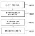
ボットの速さおよび位置の決定は、例えば、適切なフィルタを利用するモデルおよび適切なフィルタを利用しないモデルの両方を用いて実行されてもよいことに留意する。実施形態においてコントローラ1220は、ボット110の位置/速さの決定および状態推測のときに、駆動ホイールエンコーダ381、382からの誤ったデータをフィルタにかけるように構成されてもよい。一例として、コントローラ1220は、ボットの状態推測および位置計算におけるホイールの滑り誤差の影響を実質的に取り除くために、例えば、カルマン(Kalman)(または他の適切な)フィルタを含んでいてもよい。一態様においてコントローラ1220は、各センサの移行の事象(例えば、センサが搬送デッキ130B上に適切なガイド線を検出したとき、図6参照)に関する任意の適切な時間データと共に、実質的にリアルタイムなエンコーダの更新(例えば、2kHzで、0.5ミリ秒毎、50ミリ秒毎、または他の任意の適切な周波数または時間増分で)を用いて使用され得る拡張カルマンフィルタ1220Kを含んでいてもよい。図6Aを参照すると、拡張カルマンフィルタを用いるボット位置決定方法が示されている。一般に、ボット110の位置の計算は、ボット110の位置を決定するため、および/またはセンサ380A、380Bの移行を予期するために、エンコーダ381、382の1つまたは2つ以上などの任意の適切なエンコーダから受信されたデータを適用する(図6A、ブロック16000)ことによって、拡張カルマンフィルタを用いて実行されてもよい。しかしながら、図6Aに示される一般的な方法の変形例として、ボット位置を見つけるカルマンモデルは、周期的に更新されてもよい。より詳細には、センサデータは、ガイド線391~394(理解されるように、搬送デッキに沿ったボット移動に対して横方向に所定の間隔で搬送デッキ130B上に配置される付加的なガイド線391Aが、図6に示されているように設けられてもよい)などの適切なガイド線にわたって、各センサ380A、380Bの移行において受信されてもよく、これは移行の時間、および、必要に応じてガイド線の身元および/または位置を含んでいる(図6A、ブロック16001)。センサ380A、380Bからのデータに基づき、位置に関して期待された移行の時間と、測定された移行の時間との間で誤差が計算されてもよい(図6A、ブロック16002)。この誤差はその後、ホイールエンコーダ381、382によって判定される、後続のボットの位置決めのより正確な推定のために、拡張カルマンフィルタを更新するために使用されてもよい(図6A、16003)。一般に、ホイールエンコーダおよびラインセンサのデータの1つまたは2つ以上は、ボット110の制御のためにボット位置決めデータを提供するために使用され、一方で、実際に検出されたガイド線の移行は、ボット位置決めモデル、例えば拡張カルマンフィルタの方程式を更新するために使用されてもよい。It is noted that the determination of the bot's speed and position may be performed using, for example, both models that utilize appropriate filters and models that do not utilize appropriate filters. In an embodiment, the
例として、例えば搬送デッキ130B上で、所定位置(Xe、Ye)に配置され、推定速度および加速度V、aで移動しているボットに対して、モデルは、時間Teでラインセンサ380A、380Bによって感知または移行されるガイド線を推定してもよく、システムは、時間Tsでガイド線の実際の移行を識別してもよい。エンコーダ381、382の時間Ts(または任意にはタイムスタンプで)は、以下に示されるような誤差を生じるおそれがある。 As an example, for a bot positioned at a given position (Xe, Ye) and moving with an estimated velocity and acceleration V, a, e.g., on

その後、拡張カルマンフィルタの方程式は、例えば、Arthur Gelb著の「Applied Optimal Estimation」(MIT Press 1794)に記載されるように用いられてもよい。Gelbに記載された公式化の適応は、システムモデル:

状態推定の伝搬が

The propagation of state estimates is
この一般化された手法は、ボット110の位置を特定するためにいくつかのセンサの事象を要することよりも、むしろ、顕著な利点として、個別のセンサの事象を使用することを次第に可能にする。図6Aでは特定のステップの命令が実施されているが、示される動作はボット110の作動中繰り返して行われており、ステップの特定の命令またはタイミングは推定されるべきではないということが理解されるべきである。それでもなお、一般に、いくつかの実施において、ホイールエンコーダ381、382からのエンコーダデータはリアルタイムで実質的に連続的に提供され得る一方で、ガイド線391~394(および391A)のラインセンサ380A、380Bの移行は、ボットが、例えば搬送デッキ130B上を行き来するときに断続的に生じ得るということが言える。また、拡張カルマンフィルタは、エンコーダのデータをボットの位置情報に変換するための1つの有用な手法であるが、他のフィルタまたは線形モデリング技術も同様に適用されてもよいということが理解されるべきである。This generalized approach increasingly allows for the use of individual sensor events as a distinct advantage, rather than requiring several sensor events to determine the location of the
エンコーダ381、382からのデータは、例えば搬送デッキ130B上での、ガイド線GL(図6)からのボットの逸脱に応じて、コントローラ1220に信号を提供する1つまたは2つ以上のライン追従センサ380A、380Bからの信号に基づいて、さらに重み付けされてもよい。例えば、駆動ホイール1211、1212の1つが滑ると、駆動ホイール1211、1212の間で差動トルクが生じ、これはボット110を方向転換させ、ガイド線GLから逸脱させる。The data from the
ボットコントローラ1220は、例えば、保管および取り出しシステムの他の位置追跡機構と組み合わされたホイールエンコーダ381、382を用いて、ボットの位置を決定するように構成されてもよい。実施形態において、取り出し通路130Aにあるときには、ホイールエンコーダ381、382は、「BOT POSITION SENSING」と題された、代理人整理番号が1127P014267-US(PAR)の米国仮特許出願に記載されるように、細長の薄片の計数(例えば、1つまたは2つ以上のスラット検出センサ387を備える保管棚上で、細長の薄片に関するボットの位置を追跡する)と組み合わせて用いられてもよく、この出願はすでに参照により本明細書に含まれている。実施形態において、搬送デッキ130B上を移動するときには、コントローラ1220は、搬送デッキ130Bの床部(例えば、駆動面)上のガイド線391~395の追従と組み合わせてホイールエンコーダ381、382を用いるように構成されてもよい。図4Eおよび図6を参照すると、搬送デッキ130B上を移動するときに、ボットの1つまたは2つ以上のライン追従センサ380A、380Bは、ガイド線391~395を検出する(図6B、ブロック17000)。コントローラ1220は1つまたは2つ以上のライン追従センサ380A、380Bの1つから信号を受け取り(図6B、ブロック17001)、それに応じて、ガイド線391~395の所望の1つに沿ってボットを移動させ続けるために、(例えば、上述のようにボットを旋回させるようにそれぞれのホイールに印加されるトルクを調節することによって)個別の駆動原動機383、384を駆動する(図6B、17002)。図6に見られるように、搬送デッキ130B中を走る各ガイド線GLは、例えば、搬送デッキの旋回点に配置されたガイド線392および取り出し通路130Aの位置に配置されたガイド線391、393、394等の横方向のガイド線によって交差される。これらガイド線391~395のそれぞれの交差地点R、Pは、例えば、ボット110のメモリや制御サーバ120等の、ボット110によってアクセス可能な任意の適切なメモリに記憶されている、既知の所定の位置にあってもよい。交差地点R、Pが、ボット110から離れた、例えば制御サーバのメモリに記憶されている場合、ボット110は、その情報がボット110にダウンロードされるか、ボット110によって遠隔に読み取られるように、任意の適切な方法で交差地点の情報にアクセスするように構成されてもよい。 The
ボット移動の1つの例示的な動作では、例えば搬送デッキ130B上の、ボット110の検証または位置の検証は、米国特許出願第12/757,312号明細書(すでに参照により本明細書に含まれている)に記載の方法と実質的に同様の方法で、搬送デッキ130B上の交差地点/位置の基準線R、Pから判断されてもよい。例えば、ボット110が、例えばガイド線395に沿って移動すると、ボットは交差地点Pを通過し、交差地点Pの所定の位置を用いて、ボットの位置を検証する。この時点で、ホイールエンコーダからのデータはリセットされてもよい(図6B、ブロック17004)ので、エンコーダは、例えば、ボット110が移動した距離を交差地点P(すでに検証されている)から開始して増分だけを追跡し、例えば、コントローラ1220は、判明した最後のボット位置に関してボット位置を推定できる(図6B、ブロック17005)。ホイールエンコーダのデータをリセットすることは、ホイールエンコーダにより生じる任意の公差および/または誤差の累積を実質的に取り除き得ることに留意する。ボット110がガイド線395に沿って移動し続けると、ボット110は第2の交差地点Rを検出する。実質的に第2の交差地点Rがボット110によって検出されたときに、コントローラ1220は、ホイールエンコーダ381、382から判断されたボット110の推定位置および最新の検証されたボット位置(この例においては交差地点P)を用い、推定されたボット位置を交差地点Rの所定位置と比較する(図6B、ブロック17006)。推定されたボット位置が、交差地点Rの所定位置とほぼ一致する場合には、コントローラはボット110の位置を正しいと認めるか、あるいは適格性を認め、それに応じてボット110の位置を更新する(図6B、17007)。コントローラ1220は、任意の適切な方法でボットの位置を検証あるいはその適格性を認めるように構成されてもよく、例えば、上述のような拡張カルマンフィルタを通してもよい。理解されるように、ホイールエンコーダ381、382およびライン追従を用いたボットの位置/場所の決定の間、コントローラ1220は、上述の方法でホイールの滑りを考慮するように構成されてもよい。推定された位置が交差地点Rの所定位置と一致しない場合、ガイド線394に応じて(位置Rで)1つまたは2つ以上のライン追従センサ380A、380Bにより生じられた信号は無視されてもよく、ボットの位置は、ボットの推定位置を用いて次の交差地点が検証されるか、あるいは適格性を認められる(図6B、ブロック17007)まで、ホイールエンコーダ381、382を用いて推定される(図6B、ブロック17008)。実施形態において、ボット110の推定位置および所定の交差地点が一致しない場合、ボット110は、例えば、最後の既知の位置への復帰およびエンコーダ情報のリセット等の、任意の適切な方法でボットの位置を検証するように構成されてもよい。In one exemplary operation of bot movement, verification of the
図4Eおよび6を参照すると、ボットコントローラ1220(または上述の遠隔コントローラ等の、ボットを制御するように構成された他の適切なコントローラ)は、例えば、ボットの運動状態(例えば、それぞれ時間tに対する、位置X、Y;位置進度または
一例において、コマンドの論理は、例えば、コントローラ1220が、ボットの速さ、加速度、および方向を知り、所定の方向の経路および速さを維持するための、例えば、駆動原動機383、384への補正制御命令を計算することを可能にしてもよい。従来の目的では、ボットのY(例えば、長手方向)位置は、所定の基準線または移動の線(この例においては、例えば、線395)と略平行の方向における、例えば、線交差地点R、Pの間での、または他の任意の適切な横方向の基準線の間でのボット位置の推定であってもよい。ボットのX(横方向)位置は、所定の基準線391~395を実質的に横切る方向における、例えば、ボットの1自由度の軸110Xと所定の基準線391~395との間のずれの量の推定であってもよい。ヨー角度α(例えば、所定の基準線に関する逸脱/収束角度)は、ボットの1自由度の軸110Xと、所定の基準線391~395との間の角度の推定であってもよい。コントローラ1220の状態推測モジュール1220Eは、例えば、ボットに及ぼされる力Fx、Fy、駆動原動機383、384によって印加される差動トルクT、ボットの位置進度または速さ(例えば、直線または角度を有する/ヨー速度)および/またはボット110の位置進度の変化(例えば、加速度)等の動的状態およびコマンドを決定あるいは推定するように構成されていてもよい。In one example, the command logic may, for example, allow the
上述のホイールエンコーダ381、382およびライン追従センサ380A、380Bに加えて、ボット110は、一次元または二次元の加速度計等の、任意の適切な慣性センサ389を含んでいてもよいし、含んでいなくてもよい。コントローラは、ボット110の状態を推測するために、慣性センサ389からの信号を、ホイールエンコーダ381、382およびライン追従センサ380A、380Bからのホイール走行距離情報と組み合わせて用いるように構成されてもよい。In addition to the
状態推測モジュール1220Eと共に用いるために、例えば、ホイールエンコーダ381、382、ライン追従センサ380A、380Bおよび慣性センサ389からの入力がコントローラ1220に提供されてもよい(図6C、ブロック18000)。状態推測器に用いるために、スラットセンサ(例えば、保管棚の細長の薄片を感知するセンサ)からの入力もコントローラに提供されてもよい。ストレージスラットセンサの一例は、「BOT POSITION SENSING」と題され、代理人整理番号が1127P014267-US(PAR)の米国仮特許出願に見られ、この出願はすでに参照により本明細書に含まれている。 For example, inputs from
実施形態においてボットは、例えば、定常状態の動作(例えば、加速/減速がない)と、動的な状態の動作(例えば、加速/減速中)とを有していてもよい。差動原動機のトルクTが実質的にゼロに等しい定常動作の間、状態推測モジュールは、例えば、上述のようにホイール走行距離から、長手方向の位置Yおよび


また図5A~5Eを参照すると、例示的な一実施形態において、コントローラ1220は、ボット110の状態に基づきキャスタ1262の固定を解除するためにアクチュエータ420の作動を命じてもよいので、ボットのヨー角度αを補正するために迅速な操舵応答が入手され得る。ボットのヨー角度αは、キャスタが固定された状態で補正されてもよく、これはボットの安定性が向上した、より低速の操舵応答を提供し得る。コントローラ1220は、ボット110のヨー角度αを補正するために駆動ホイール1211、1212に最大値の差動トルクTが印加されるように、駆動ホイール1211、1212に印加する差動トルクTの推定値を知ってもよい(状態推測モジュール1220Eを介して)。


ヨー角度αの推定値に基づき差動トルクTが印加されると、コントローラ1220はライン追従センサ380A、380Bの1つまたは2つ以上からガイド線感知信号を受け取るために待機する。ライン感知信号が受け取られると、コントローラ1220は、差動トルクTの減少を命令し、またボットが実質的に所望のガイド線391~395に沿って移動するように、ヨー角度αが所定の値になるまでボット110の運動情報を更新し続けてもよい。差動トルクTは、例えば、ガイド線391~395の中央への接近速度

ボット動作の動的な状態において、例えば、ボット110が正の加速または負の加速(すなわち、減速)を受けており、差動トルクTがほぼゼロであるかゼロよりも大きい場合、ボットの運動状態は、ボットの定常状態の動作に関して記載された上述の方法と同様の方法で決定されてもよい。ボット110の移動が、例えば、取り出し通路130Aでの接触直線誘導システム(例えば、軌道またはレール)によって誘導される場合(例えば、すでに本明細書に含まれている、「AUTONOMOUS TRANSPORTS FOR STORAGE AND RETRIEVAL SYSTEMS」と題された米国特許出願第12/757,312号明細書を参照)には、例えば、ライン追従センサ380A、380Bによってコントローラ1220に送られるデータはないことに留意する。このように、接触により直線的に誘導される移動領域内でのボット110の状態推測は、長手方向のみである。取り出し通路内でのボット110の位置は、例えば、すでに参照によって本明細書に含まれている、「BOT POSITION SENSING」と題され、代理人整理番号が1127P014267-US(PAR)の米国仮特許出願に記載されるような保管棚の細長の薄片の位置の検証と組み合わせて、状態推測モジュール(直接的なホイールエンコーダの読み取りを伴わない)によって決定されてもよい。In a dynamic state of bot operation, for example when the
さらに図4Aおよび4Bならびに図7、8、9Aおよび9Bを参照すると、少なくとも1つの駆動セクション110Dは、任意の適切な態様にてフレームに接続されてもよい。一態様において、駆動セクション110Dは、任意の適切な、可動に連結するシステムによってフレームに接続されてもよい。実施形態において可動に連結するシステムは、任意の適切な態様で駆動セクション110Dをフレーム110FRに枢動可能(あるいは移動可能)に連結し、少なくとも1つの駆動セクション110Dとフレーム110Fとの間の相対的な回転を可能にする支持システムであってもよい。枢動による結合が図示および記載されているが、別の態様において結合は、単に例示的な目的で、これらに限定されるわけではないが、直線的に可動な連結、回転可能な連結またはその組み合わせを含む、任意の適切な多関節の連結であってもよいことに留意されたい。理解されるように、ボットは4点(例えば、ボットの実質的な隅にそれぞれ配置されている1つのホイール1261、1262、1211、1212)で支持されてもよい。仮に4つ全ての支持ホイールがフレーム110FRに強固に接続され、ボットが、例えば、搬送デッキ130Bおよび/または取り出し通路130Aの移動面上のバンプまたは他の上昇した/平らでない構造を越えて移動する場合には、ボットの1つまたは2つ以上のホイールは、移動面から離昇されるおそれがあり、これは例えば、ホイールの牽引力の損失を引き起こし得る。また、理解されるように、保管および取り出しシステム100内にあり得るボットの位置は、例えば、その開示がすでに参照によって本明細書に含まれている、「BOT POSITION SENSING」と題され代理人番号が1127P014267-US(PAR)である米国仮特許出願に記載されるように、少なくとも部分的に任意の適切なホイール位置情報システムを用いて決定されてもよく、これはホイールの牽引力の損失が、誤った位置情報の読み取りを引き起こすおそれがあるからである。少なくとも1つの駆動セクション110Dとフレーム110FRとの間の可動の接続は、正確なボットの位置決めが決定され得るように、駆動ホイール1211、1212が移動面から離昇することを実質的に防ぐ。4A and 4B and 7, 8, 9A and 9B, the at least one
実施形態において、フレーム110FRは、枢動または連結部材10400を含んでいてもよい。枢動部材10400は、ボット(およびその上の任意の積載物)の重量がボット110の端部1501で中央に支持され得るように、ボット110の長手方向の軸110Xと実質的に一致して配置されてもよい。枢動部材10400は、フレーム110FRの端部1501上の任意の位置に適切に配置されてもよいことに留意する。枢動部材は、フレーム110FRと一体に形成されてもよいし、任意の適切な態様でフレームに取り付けられてもよい。この例において枢動部材10400は、対応する少なくとも1つの駆動セクション110Dの枢動軸500を受け入れるように構成された任意の適切な凹部または開口10400Rを含んでいてもよい。In an embodiment, the frame 110FR may include a pivot or
少なくとも1つの駆動セクション110Dが、枢動部材10400の凹部10400R内に受け入れられるように構成された枢動軸500を含んでいてもよく、またはフレーム110FRが枢動軸を含み、駆動セクション110Dは枢動部材を含んでいてもよい。理解されるように、実施形態においてフレームおよび駆動セクションは、駆動セクションがフレームに関して枢動することを可能にするために、任意の適切な構造を有していてもよい。この例において、枢動軸500は、クリップ、ボルト、スナップまたは任意の他の適切な保持素子等によって、任意の適切な態様にて枢動部材10400内に枢動可能に保持されてもよい。枢動軸500および枢動部材10400は、駆動セクション110Dが、矢印550の方向でフレーム100Fの長手方向の軸100Xに対して軸方向に枢動するように構成されてもよい。駆動セクション110Dとフレーム110FRとの間の接続は、駆動セクション110Dおよびフレーム110FRが任意の適切な1つまたは2つ以上の方向で互いに対して枢動することを可能にするように構成されてもよい。At least one
実施形態において駆動セクション110Dは、1つまたは2つ以上のガイド部材530を含んでいてもよい。ガイド部材530は、ホイール、スライダまたは、例えば、駆動セクション110Dおよびフレーム110FRが枢動連結部510(例えば、枢動軸500および枢動部材10400により形成される)を通して相互に連結されるときに、フレーム110FRの表面535と係合する、他の任意の適切な構造であってもよい。フレーム110FRはまた、フレーム110FRおよび駆動セクション110Dが相互に可動に連結されたときに、ガイド部材が駆動セクション110Dの表面と係合するように、ガイド部材530を含んでいてもよい。この例においてガイド部材530は、駆動セクション110Dに取り付けられていてもよく、これによりガイド部材530は、駆動セクション110Dとフレーム110FRとの間の相対的な枢動(または別の方法での)動作を可能にする一方で、部分的に、ボット110の実質的に強固な長手方向の軸を実質的に維持する。例えば、実施形態においてガイド部材530は、任意の適切な距離X1、X2だけ、枢動結合部510の枢動軸510Pから横方向に(例えば、X軸に沿って)離間されている。枢動軸510Pとガイド部材530との間の距離X1、X2は、駆動セクション110Dとフレーム110FRとの間の(例えば、X-Y面の矢印598方向の)ヨーイング動作を、(ガイド部材530とフレームの表面535との間の接触を通して)実質的に防ぎ得る。ガイド部材530の少なくとも1つも、任意の適切な距離Z1、Z2だけ、枢動軸510Pから垂直方向に(例えば、Z軸に沿って)離間されていてもよい。枢動軸510Pとガイド部材530の少なくとも1つとの間の距離Z1、Z2は、駆動セクション110Dとフレーム110FRとの間の(例えば、Y-Z面の矢印599方向の)ピッチング動作を、(ガイド部材530の1つとフレームの表面535との間の接触を通して)実質的に防ぎ得る。この例において、ガイド部材530A~530Dは、2つのガイド部材530A、530Bが枢動軸510Pの上部に距離Z1だけ垂直に離間され、2つのガイド部材530C、530Dが枢動軸510Pの下部に距離Z2だけ垂直に離間されるように、駆動セクション110Dの境界面110DSの隅に実質的に配置されてもよい。代替的には、ガイド部材530A~530Dの全てが、枢動軸の上部または枢動軸の下部に配置されてもよいことに留意する。ガイド部材530A、530Dは、(枢動軸の第1の面上で)枢動軸から距離X1だけ横方向に離間されてもよく、ガイド部材530B、530Cは、(枢動軸の反対側の第2の面上で)枢動軸から距離X2だけ横方向に離間されてもよい。実施形態においては、駆動セクション110Dとフレーム110FRとの間のヨーイングおよびピッチングを防ぐために(例えば、枢動軸から離間されて)配置される任意の適切な数のガイド部材があってもよい。In an embodiment, the
実施形態において、連結された駆動セクション110Dおよびフレーム110FRの(例えば、ヨーおよびピッチにおける)軸安定性は、ガイド部材530A~530Dの1つまたは2つ以上、および枢動部材10400と枢動軸500との間の接続を通してもたらされてもよい。例えば、1つの例示的な実施形態において、枢動軸500は、ガイド部材530A~530Dがフレームの表面535に対して実質的に保持されるように、枢動部材10400内に軸方向に固定されてもよい。ガイドホイール530、枢動軸500および枢動部材10400の1つまたは2つ以上は、駆動セクション110Dとフレーム110FRとの間の、X-Y面およびY-Z面でのあらゆる相対的動作(例えば、ヨーイングおよびピッチング)を吸収するか、実質的に取り除くために、長手方向またはX方向において調節可能であってもよい。駆動セクション110Dとフレーム110FRとの間の長手方向の実質的に強固な結合を提供するために、ガイドホイールは任意の適切な態様でフレーム110の表面535に対して保持されてもよいことに留意する。理解されるように、ガイド部材530および/または枢動連結部510は、X-Z面の矢印550方向での駆動セクション110Dとフレーム110FRとの間の相対的回転(例えば、ローリング)のみを可能にする。別の態様において駆動セクションとフレームとの間の連結は、駆動セクションとフレームとの間の任意の適切な相対的動作を可能にしてもよい。In embodiments, axial stability (e.g., in yaw and pitch) of the coupled
理解されるように、(X-Z面の)矢印550の方向における駆動セクション110Dとフレーム110FRとの間の回転または枢動は、任意の適切な態様にて制限されてもよい。1つの例示的な実施形態において図8、11Aおよび11Bを参照すると、突出部材560、561は、駆動セクション110Dの境界面110DSから延伸していてもよい。この例において、突出部材560、561は、駆動セクション110Dの側面の両端に配置されているが、突出部材は、駆動セクション110Dとフレーム110FRとの間の旋回軸での移動を制限するために任意の適切な位置に配置されてもよい。突出部材560、561は、例えばピン、ブッシング、ねじ棒、鋲などの、例えば、凹部または溝560Gと係合するように構成された、任意の適切な部材であってもよい。突出部材560、561は、突出部材560に関して記載されているが、突出部材561は突出部材560と実質的に同様であることに留意する。この例において突出部材560は鋲またはピンであってもよい。適切なブッシング560Bが、突出部材560に接続されてもよい。一例において、突出部材560およびブッシング560Bは、互いに対して一体に形成されてもよい。別の例において、ブッシング560Bは、ブッシング560Bと突出部材560との間の締まり嵌めまたは他の任意の適切な方法で、機械的または化学的な締結要素によって、突出部材560に固定されてもよい。実施形態においてブッシング560Bは、駆動セクション110Dがその移動限度に達すると、駆動セクション110Dの旋回軸での移動を実質的に緩衝するように構成されてもよい。代替的には、ブッシングは枢動する駆動セクション110Dのための、実質的な硬質の停止部を備えてもよい。駆動セクション110Dの移動限度は、フレーム110FRに形成された凹部または溝560Gによってもたらされてもよく、これは突出部材560、561のそれぞれに対応している。突出部材560、561のそれぞれのためのブッシング560Bおよび対応する溝560Bは、ボット110が略水平面上にあるときに、ブッシング560Bが、対応する溝560Bの端部から任意の適切な所定距離Nだけ離間されているように構成されてもよい。ブッシング560Bおよび溝560Gは、駆動セクション110Dの枢動動作の間、ブッシングが溝560G内で実質的に矢印710の方向に実質的に干渉なく移動するような大きさにされてもよい。ブッシング560Bと溝560Gの端部との間の接触は、駆動セクション110Dとフレーム110FRとの間の移動(例えば、枢動動作)を制限する。As will be appreciated, rotation or pivoting between the
図4B、10A、10B、10C、10D、11Aおよび11Bを参照すると、駆動セクション110Dとフレーム110FRとの間の相対的な旋回軸での動作は、保管セクション230A、230Bの保管棚またはマルチレベル垂直コンベヤ150A、150Bの1つからピックフェースを取り出す/配置するために、ボットアーム110A(図4A)が横方向に延伸されるときに、フレーム110FRと駆動セクション110Dとの間の動きを可能にしてもよい。ボット110は、ボットアーム110Aが横方向または他の任意の適切な方向に延伸されると、駆動セクション110Dとフレーム110FRとの間の相対的な動きを実質的に防ぐために、ボットのサスペンションを受動的に閉鎖するように構成される(例えば、ボットアーム110Aの延伸が、サスペンションの固定を受動的に引き起こす)1つまたは2つ以上の固定装置10600を有する、固定システムまたは閉鎖機構を含んでいてもよい。実施形態は、アームが延伸されたときの、サスペンションの受動的な固定に関して記載されているが、別の態様においては、固定装置10600は、アーム位置とは無関係に、任意の適切な態様にてサスペンションを能動的に固定するように構成されてもよい。固定装置10600は、枢動軸510Pから任意の適切な所定距離だけ離れて配置されてもよい。一例において1つまたは2つ以上の固定装置10600は、実質的にフレーム110FRの各サイドエッジ110E1、110E2に配置されてもよいし、それらに隣接して配置されてもよい。固定装置10600はエッジ110E1、110E2のそれぞれに隣接して示されているが、単一の固定装置がエッジ110A1、110E2の1つのみに沿って配置されてもよい。さらに、任意の適切な数の固定装置10600が、例えば、枢動軸510Pに対して、任意の適切な1つまたは2つ以上の位置に配置されてもよい。4B, 10A, 10B, 10C, 10D, 11A and 11B, the relative pivotal movement between the
この例において、固定装置10600は、本体10601、弾性部材10602およびレバー部材10603を含んでいてもよい。本体は、任意の適切な構成を有していてよく、図面においては、単に例示的な目的で略矩形形状を有するものとして示されている。この例において本体は、フレーム110FRへの取り付けのために構成されてもよいが、本体は、駆動セクション110Dへの取り付けのために構成されてもよい。本体10601は、凹部10602Rを含んでいてもよく、これは弾性部材10602が凹部10602R内に挿入され得るのに適切な大きさにされている。この例において、弾性部材10602は、引張バネであってもよいが、別の実施形態において弾性部材10602は、板バネ、圧縮バネまたはトーションバネ等の任意の適切な弾性部材であってもよく、本体10601は、任意の適切な態様で弾性部材と接続するか、弾性部材を収容するように適切に構成されてもよい。レバー部材10603は、任意の適切な方法で、例えば、単に例示的な目的であるが、枢動ピン10610を通して、本体10601に枢動可能に取り付けられてもよい。レバー部材10603は、第1の表面10603Aと、以下に記載するようにカム751と係合する第2の表面10603Bとを有する複合表面、および以下に記載するように係合部材750と係合する表面10603Eを有していてもよい。本体10601は、本体が、例えばフレーム110FRに取り付けられると、フレーム110FRおよび駆動セクション110Dの境界面535、110DSと略平行であってもよい矢印10620の方向にレバー部材10603が枢動するように構成されてもよい。弾性部材10602は、レバー部材10603に対して配置されてもよく、および/またはレバー部材10602は、本体10601に形成された開口10611に向かって矢印798の方向にレバー部材10603を回転させるために、弾性部材10602がレバー部材10603と係合するように構成されてもよく、その結果、固定装置10600は、アームが延伸されるとサスペンション固定位置(例えば、矢印798の方向)に付勢され、アームの後退は、サスペンションを固定するために弾性部材10602によりもたらされる力に抗って、アームが矢印799の方向に移動するように作用する。In this example, the fixing
固定システムも、固定装置10600のそれぞれに対応する係合部材750を含んでいてもよい。係合部材750は、係合部材750が境界面110DSから延伸するように、例えば、駆動セクション110Dへの取り付けのために構成されてもよい。係合部材750は、レバー部材10603の表面10603Eと相互作用するために、本体の開口10611を通って延伸するように配置されてもよい。係合部材750および/または開口10611は、駆動セクション110Dおよびフレーム110FRが互いに対して枢動するときに、開口10611内での係合部材750の動作を可能にするように構成されてもよい。The fastening system may also include an
1つまたは2つ以上のカムまたは遊動体751は、フレーム110FRに回転可能に取り付けられてもよい。各カム751は、例えば、1つまたは2つ以上の固定装置10600のレバー部材10603の、それぞれの表面10603A、10603B(または他の任意の適切な表面)と相互作用するために、フレーム110FRの任意の適切な位置に配置されてもよい。例えば、カム751は、ボットアーム110Aが延伸および後退させられると、例えばスライド部材1530Dのそれぞれと共に移動してもよい。ボットアーム110Aが延伸されると、カム751は矢印798の方向に移動し、表面10603Bから表面10603Aに移動して、最終的にレバー10603から離れ、これはボット110のサスペンションを固定するために、レバー部材が開口10611に向かって矢印798の方向に枢動することを可能にする。理解されるように、弾性部材10602によってレバー部材10603に及ぼされる力は、カム751の表面に対抗してレバー部材を保持し得るので、カム751が移動すると、レバー部材は、ボット110のサスペンションを固定および解除するために開口10611に向かって、または開口10611から離れて移動させられる。ボットアーム110Aが後退させられると、カム751は矢印799の方向に移動するので、カム751はレバー10603の表面10603Aと係合し、その後その表面10603Bと係合し、これはボット110のサスペンションを解放するためにレバーを矢印799の方向に枢動させる。図10Dから最もよく分かるように、カム751がレバーの表面10603Bと係合されると、レバー部材10603の表面10603Bは、カム751が、(モータやクリップ(clip)からなどの)外部の影響を実質的に受けずに、例えば、ボットアームが延伸されると解消される、弾性部材10602によってもたらされるカム751と表面10603Bとの間の通常の力で定位置に実質的に留まるように、このような方法で向きを合わされる。代替的な実施形態において、カム751は、静止していてもよく(例えば、スライド部材1530Dと共に移動しない)、ボットのサスペンションを固定および固定解除するために、カムの駆動回転がレバー10603の旋回軸での動作を引き起こすように、任意の適切な駆動システムによって駆動されてもよい。One or more cams or
上述のように、係合部材750は、レバー部材10603と相互作用するために、開口を通して延伸する。カム751の矢印798方向への動きは、レバー部材10603の矢印798方向への動きを可能にするので、レバー部材10603の表面10603Eは係合部材750に接触し、本体10601の任意の適切な表面に対して係合部材750を挟むかまたは締め付ける。例えば、係合部材750は、係合部材750の少なくとも一部がブロック部材601Bの表面とレバー部材10603との間に配置されるように、本体10601のブロック部材601B内に延伸してもよい(例えば、係合部材は、カムが回転されるとレバー部材とブロックの表面との間で挟まれるかまたは締め付けられる)。係合部材750上に及ぼされる挟む力または締め付け力は、ボットアーム110Aが、例えば、ボット110と保管棚またはマルチレベル垂直コンベヤとの間でピックフェースを搬送するために横方向に延伸されると、フレーム110FRに対して所定位置で駆動セクション110Dを実質的に強固に保持するのに十分な所定の力であってもよい(例えば、駆動セクションおよびフレームが、単一の実質的に堅固な構造を形成するように、フレームと駆動セクションとの間の枢動を実質的に防ぐ)。As described above, the
実施形態において、1つまたは2つ以上のカム751は、ボット110のサスペンションを受動的に固定するために、任意の適切なボットアーム駆動システム770に適切に接続されてもよい。例えば、1つまたは2つ以上のカム751とボットアーム駆動システム770との間の接続は、ボットのサスペンションを受動的/自動的に固定するために、ボットアーム110Aが延伸されると固定装置10600の動作を引き起こしてもよい。カム751はまた、ボットのサスペンションがボットアームの位置とは無関係に、能動的に固定/固定解除され得るように、独立して動作可能な駆動システムによって駆動されてもよい。実施形態において、ボットアーム110Aが所定の後退位置またはホーム位置にあるときには、固定装置10600は自動的に解放され、駆動セクション110Dおよびフレーム110FRは互いに対して枢動(あるいは移動)できる。例えば、ボット110の動作中、ボット110は、ボットアーム110Aがホーム(例えば、後退した)位置にある状態で、取り出し通路130Aおよび搬送デッキ130Bを行き来してもよい。ボットアーム110Aがホーム位置にある状態で、ボットのサスペンションは固定を解除され、駆動セクション110Dおよびフレーム110FRは互いに対して自由に枢動するので、サスペンションは取り出し通路130Aおよび搬送デッキ130Bの移動面に順応できる。ボットアーム110Aが延伸されると、カム751は、係合部材750を挟むかまたは締め付けて、ボットのサスペンションを受動的に固定する目的で、レバー部材10603が矢印798の方向に移動することを可能にするために、(カム751のボットアーム駆動システム770への接続によって)受動的に移動させられ、それにより駆動セクション110Dおよびフレーム110FRは、ピックフェースが配置または搬送される面に対して延伸されたアーム110Aを傾かせるおそれのあるフレーム110FRのあらゆる回転または傾きを実質的に取り除く、単一の実質的に強固な、または堅固な構造を形成する。ボットアーム110Aがホーム位置に後退させられると、カム751は、係合部材750を解放し、ボットのサスペンションを受動的に固定解除する目的で、レバー部材10603を矢印799の方向に移動させるために、受動的に移動させられる。カムは、固定装置の動作を引き起こすために、任意の適切な態様にて受動的または能動的に駆動されてもよいことに留意する。In an embodiment, the one or
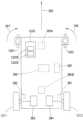
図12Aおよび12Bを参照すると、ボットは、ボットフレーム110FRの外側の隅に配置される誘導ホイール351~354等の、対になったガイドを含んでいてもよい。ガイドは、本明細書においては誘導ホイールとして記載されているが、代替的な実施形態においては、任意の適切な種類のガイドが用いられてもよい。ガイドの1つのペアが、ボット110の各端部に配置されてもよい。例えば、誘導ホイール351、352がボットの前部1500に配置され、誘導ホイール353、354がボット110の後部に配置されてもよい。各誘導ホイールのペアは、ボット110の両側に配置される、実質的に適合的(compliant)な誘導ホイール352、353と、実質的に固定的な誘導ホイール351、354とを含んでいてもよい。単に例示的な目的で、実施形態においては、実質的に固定的な誘導ホイールが、搬送アーム110Aがそこから延伸するボットの側に配置されてもよい。実施形態において実質的に固定的な誘導ホイールは、代替的には、ボットアームが延伸する側と反対側のボットの側に配置されてもよい。実施形態において、実質的に固定的な誘導ホイールおよび実質的に適合的な誘導ホイールは、ボット上で任意の適切な位置の配列を有していてもよいことに留意する。12A and 12B, the bot may include a pair of guides, such as guide wheels 351-354, disposed at the outer corners of the bot frame 110FR. Although the guides are described herein as guide wheels, in alternative embodiments, any suitable type of guide may be used. One pair of guides may be disposed at each end of the
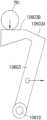
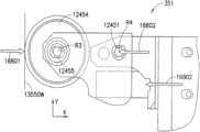
図12Aに示されるように、実質的に適合的な誘導ホイール352、353は、取り付け部材12400上でボット110に枢動するように取り付けられてもよく、枢動部材12401、緩衝器12402、誘導ホイールフォーク12403、ホイール12404およびホイール保持部12405を含んでいてもよい。実施形態において、誘導ホイールフォーク12403は、第1の端部を枢動部材12401によって取り付け部材12400に枢動可能に取り付けられている。枢動部材は任意の適切な軸または旋回軸であってもよい。ホイール12404は、ホイール保持部12405によって誘導ホイールフォーク12403の第2の端部に回転可能に取り付けられている。ホイール保持部12405は、任意の適切な軸または他の保持機構であってもよい。緩衝器12402は、ホイール12404の移動を実質的に制限する一方で、ホイールがホイール保持部12405の周りを回転することを可能にするために、ボットフレーム110FRとホイール12404との間に取り付けられる、任意の適切な衝撃吸収材であってもよい。実施形態において、実質的に適合的な誘導ホイールは、任意の適切な構成を有していてもよいことに留意する。As shown in FIG. 12A, the substantially conforming
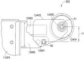
図12Bに示されるように、実質的に固定的な誘導ホイール351、354も、取り付け部材12450上でボット110に枢動可能に取り付けられていてもよく、枢動部材12451、緩衝器12452、誘導ホイールフォーク12453、ホイール12454およびホイール保持部12455を含んでいてもよい。実施形態において、誘導ホイールフォーク12453は、第1の端部を枢動部材12451によって取り付け部材12450に枢動可能に取り付けられている。枢動部材は任意の適切な軸または旋回軸であってもよい。ホイール12454は、ホイール保持部12455によって誘導ホイールフォーク12453の第2の端部に回転可能に取り付けられている。ホイール保持部12455は、任意の適切な軸または他の保持機構であってもよい。緩衝器12452は、ホイール12454の移動を実質的に制限し、ボット110に加えられる力を吸収する一方で、ホイールがホイール保持部12455の周りを回転することを可能にするために、ボットフレーム110FRとホイール12454との間に取り付けられる、任意の適切な衝撃吸収材または他の適切な弾性部材であってもよい。実施形態において、実質的に固定的な誘導ホイールは、任意の適切な構成を有していてもよいことに留意する。As shown in FIG. 12B, the substantially
図12Aおよび12Bを参照すると、実質的に適合的な誘導ホイール352、353および実質的に固定的な誘導ホイール351、354のための誘導ホイールフォーク12403、12453の回転軸R2、R4に対するホイール12404、12454の回転軸R1とR3とは、異なっていてもよいことに留意する。例えば、実質的に適合的な誘導ホイール352、353の回転軸R1は、誘導ホイールフォーク12403の回転軸R2から距離Y1だけ長手方向にずれていてもよい一方で、実質的に適合的な誘導ホイール351、354のための回転軸R3、R4は、実質的に長手方向に互いに対して並んで配置されている。これらの誘導ホイールの構成は、両方の誘導ホイールが、例えば、取り出し通路130A1~130A7に入るときに、それぞれの軸R2、R4の周りで回転することを可能にしてもよい。しかしながら、取り出し通路130A1~130A7内を移動するときには、これらの構成は軸R4の周りに実質的に固定された、実質的に固定的な誘導ホイール351、354を保持し、実質的に適合的な誘導ホイール352、353が軸R2の周りで回転することを可能にしてもよい。理解されるように、誘導ホイールは非対称に適合的な誘導部材であるので、以下により詳細に記載されるように、第1誘導部材の座標系(例えば、X-Y面)に関する所定の方向の力に対する少なくとも1つの第1誘導部材の剛性は、第2誘導部材の座標系(例えば、X-Y面)に関する所定の方向の力に対する少なくとも第2誘導部材の剛性とは異なる。12A and 12B, it is noted that the rotation axes R1 and R3 of the
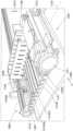
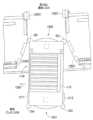
また、図3、13、14Aおよび14Bを参照すると、誘導ホイール351~354のそれぞれは、保管および取り出しシステム100の引き込み構造またはガイドと相互作用するように構成されてもよい。例えば、1つの例示的な実施形態において、角度を有する誘導部材のペア13500、13501は、搬送デッキと、例えば取り出し通路との間を移行するために、移行領域で少なくとも部分的に搬送デッキ130上に配置されてもよい。角度を有する誘導部材13500、13501は、1つまたは2つ以上の誘導ホイール351~354と協働するために任意の適切な構成を有し、少なくとも部分的にボット110を取り出し通路130A内に導く、任意の適切なガイドであってもよい。例えば、ボット110Nは、ケースユニット101を取り出し通路130A7に取り出す/配置するために、ガイド線130L4(矢印298の方向における一般的な移動方向を与える)に沿って移動していてもよい。実施形態においてケースユニットは、通路130A7の左側260に配置されてもよい。図13に見られるように、ボット搬送アーム110は、この実施形態においては、ボット110の左側(前端1500と後端1501との間に定められるボットの長手方向の軸またはY軸に対して)に延伸するように構成されている。このように、ボットが取り出し通路130A7の左側260からケースユニット101を取り出す/配置するために、ボットは、前端1500が移動方向の前にある状態で、取り出し通路を下る。ボットが取り出し通路130A7を降下するとき、独立して駆動される駆動ホイール1211、1212に差動トルクが印加され、これはボットの前端1500を矢印270の方向に振り向ける。ボット110の前端1500が矢印270の方向に転回すると、実質的に適合的な誘導ホイール352が角度を有する誘導部材13501に接触してもよい。実質的に適合的な誘導ホイール352と誘導部材13501との間の接触は、取り出し通路の誘導レール13550、13551と合わさるときにボット110を補助してもよい。例えば、ボット110が転回し続けると、実質的に適合的な誘導部材352との接触が、実質的に固定的な誘導ホイール351と誘導部材13500との間の接触をもたらすように、誘導部材13500、13501は漏斗状の配置を形成する。ボットが取り出し通路内をさらに移動すると、誘導ホイール353、354は誘導レール13550、13551と合わさるように、そのそれぞれの誘導部材13500、13501と接触してもよい。理解されるように、ボットの誘導移動の間、ボットの誘導ホイールは、常に誘導レールと接触していなくてもよい。例えば、誤差変動、レールの屈曲、保管構造物のアセンブリにおける変化は、誘導ホイールが、誘導レールの表面との接触を一時的に断つことを引き起こす場合がある。誘導レールシステムは、移動経路に沿うボット動作に実質的な抵抗を全く与えることなくボットの移動経路を維持するように構成される、対立する磁場のシステムを含み得る(例えば、ボットは磁場発生器を含み、保管構造物はそれぞれが反対の極性を有する磁場発生器を含む)ことに留意する。3, 13, 14A and 14B, each of the guide wheels 351-354 may be configured to interact with a retraction structure or guide of the storage and
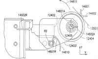
誘導ホイール352などの実質的に適合的な誘導ホイールが誘導部材13501に接触すると、X方向およびY方向の両方で、誘導部材13501によってホイール12404に力14601、14602が加えられ、ここでY方向はボット110の長手方向の軸(例えば、前後)と平行であって、X方向はY方向に対して直角(例えば、ボット110の横軸と略平行)である。これらの力14601、14602は、変換された力14601A、14602Aとしてホイール保持部12405に移される。これらの変換された力14601A、14602Aは、誘導部材13501に対して後ずさりする実質的に適合的な誘導ホイールによって、X方向およびY方向の両方に及ぼされる合力14601R、14602Rを引き起こす。誘導ホイール保持部12405の回転軸は、枢動部材12401の回転軸R2から距離Y1(図12A)だけ長手方向にずれている(例えば、Y方向に)ので、誘導ホイールに及ぼされる力は、ホイールフォーク12403(およびホイール12404)が矢印14611の方向で枢動部材12401の周りで回転するように、回転モーメント14610を引き起こす。緩衝器12402は、誘導ホイールに加えられる変換された力に部分的に抵抗するか、またはこの力を部分的に吸収し、回転モーメント14610に少なくとも部分的にいくらかの抵抗を与えてもよい。誘導ホイール352が誘導部材13501に接触し、ボットの後部1501が誘導レール13550、13551と並んだときに、実質的に適合的な誘導ホイール352上で同様のモーメントが生じてもよいことに留意する。When a substantially compliant induction wheel, such as
誘導ホイール351等の実質的に固定的な誘導ホイールが誘導部材13500に接触すると、誘導部材13500によってホイール12404に力14621、14622が加えられる。これらの力14621、14622は、変換された力621A、14622Aとしてホイール保持部12455に移される。これらの変換された力621A、14622Aは、誘導部材13500に対して後ずさりする実質的に適合的な誘導ホイールによって、X方向に及ぼされる合力14621R、14622Rを引き起こす。横方向に並んでいるホイール保持部12455および枢動部材12451の配置のために、Y方向への力のみが、ホイールフォーク12453(およびホイール12454)が矢印14613の方向において枢動部材12451の周りで回転するような回転モーメント14612を作り出すことに寄与してもよい。緩衝器12452は、誘導ホイールに加えられる変換された力に少なくとも部分的に抵抗するか、またはこの力を少なくとも部分的に吸収し、回転モーメント14612に少なくとも部分的に抵抗してもよい。誘導ホイール354が誘導部材13500に接触し、ボットの後部1501が誘導レール13550、13551と並んだときに、実質的に固定的な誘導ホイール354上で同様のモーメントが生じてもよいことに留意する。When a substantially stationary induction wheel, such as
図15、16Aおよび16Bを参照すると、一度取り出し通路130Aに入れば、保管棚600上に保管されるケースユニット101から所定の距離X1だけ離してボット110を位置づけるために、誘導ホイール351~354は誘導レール13550、13551の垂直部分13550Wに沿って走行してもよい。この例において、距離X1は、ボット110のピックフェンス1510Fと、ケースユニット101がそれに沿って並べられる所定の基準面Dとの間で決定される。取り出し通路130Aでは、レール13550の垂直部分13550Wは、誘導ホイール351等の実質的に固定的な誘導ホイールのホイール12454に対して、X方向に力16801を及ぼしてもよい。合力16802は、実質的に固定的な誘導ホイール351によって印加されてもよい。ホイール保持部12455の回転軸R3、枢動部材12451の回転軸R4および同一の横方向(例えば、X方向)の線に沿っている力16801、16802のために、実質的に固定的な誘導ホイールは、誘導ホイール351に加えられる何らの回転モーメントも伴うことなく、実質的に堅固なままである。同様の力は、実質的に固定的な誘導ホイール354上に、それにより生じてもよい。取り出し通路にある間、実質的に固定的な誘導ホイール351、354に加えられる回転モーメントがないので、誘導ホイール351、354の剛な配置は、例えば、ボット110のピックフェンス1510Fを、基準面Dから所定の横方向の距離X1だけ離れた位置に維持する。15, 16A and 16B, once in the pick-up
取り出し通路130Aにおいて、誘導ホイール352等の実質的に適合的な誘導ホイールに及ぼされる力は、実質的に固定的な誘導ホイール351、354に関して上に記載されたものと実質的に同様のものでもよい。例えば、誘導レール13551の垂直部分13551Wは、ホイール12405に対してX方向に力16803を及ぼしてもよく、これは誘導ホイール352によって生み出される、合力16804を生じる。ホイール保持部12405の回転軸R1(例えば、力16803が印加される実質的な地点)は枢動部材12401の回転軸R2から長手方向にずれているので、回転モーメント16810が生み出され、これは枢動部材12401の周りで矢印16811の方向にホイール12404(およびホイールフォーク12403)を枢動させる。ホイール12404は、緩衝器12402によって実質的に停止されるまで、枢動部材12401の周りで枢動し続けてもよい。実質的に適合的な誘導ホイール353に対抗して、またはこれに対して、同様の力が生じてもよいことに留意する。この例において、それぞれの枢動部材12401の周りでの各ホイールフォーク12403の適合的な回転と組み合わせて、そのそれぞれの実質的に適合的な誘導ホイール352、353の緩衝器16804によって印加される力(例えば、合力16804)は、ボット110を横方向に押すので、実質的に固定的なホイール351、354は、距離X1を維持するために、誘導レール13550の垂直部分13550Wに対して保持される。In the pick-up
図3を参照すると、ボット移動の一例として、ガイド線130L1に対応する経路に沿って移動するボット110Yは、取り出し通路130A5において品物を保管位置へ搬送するように指示されてもよい。しかしながら、ボット110Yは、取り出し通路130A5に対応する分岐ガイド線130S5をすでに通過していてもよい。ボットは、分岐ガイド線130S4等の、次の利用可能な分岐(例えば、別のボットによって使用されていない分岐)に出会うまで、ガイド線130L1に沿って移動し続けてもよい。ボットは分岐ガイド線130S4に入り、その後ガイド線130L3、130L4の1つに入り、そのため、ボット110は、取り出し通路130A5に対して実質的に反対の方向に移動している。ボットは取り出し通路130A5に対応する分岐ガイド線130S5に出会うまでガイド線130L3、130L4の1つに沿って移動し続けてもよく、ボットは、(例えば、レール誘導システム等の)取り出し通路130A5の誘導路に移行するか、あるいはそれに入るために、分岐ガイド線130S5に入る。3, as an example of bot movement,
上述のように、ボットが取り出し通路に入る方向(例えば、前端が前にあるか、前端が後ろにある)は、取り出し通路のいずれの側で、ケースユニットがそこから取り出されるかまたはそこに配置されるかに依存してもよい。ボット110N、110Yに関する上述の例では、ボットは前端1500が前にある状態で取り出し通路に入った。ガイド線130L1~130L4によって画定される移動経路は、ボットが、前端1500が移動方向の後ろにある状態で取り出し通路に入ることを可能にするために、少なくとも制限された双方向のボット移動をもたらしてもよい。例えば、さらに図3を参照すると、ボット110Mは、取り出し通路130A4の右側261へケースユニットを搬送するように指示されてもよい。しかしながら、ガイド線130L1~130L4のいずれか1つに沿って移動するとき、前端1500が移動方向の前にある状態で取り出し通路130A4内に移行するように、ボットがガイド線130S4上に入ることになる場合には、搬送アームの延伸は通路の間違った側に位置付けられる。ボットには、ボットの積荷台をボット内で旋回または回転させ得るターンテーブル等の、任意の適切なデバイスを装着することができ、これはボットの延伸アームが、通路の正しい側での延伸/後退のために配置されることを可能にすることに留意する。ボット110Mは、例えば、ガイド線130L4に沿ってボット110Mが取り出し通路130A4を越えて移動するように構成されてもよい。任意の適切なボット衝突の回避または他の通行管理は、ボットが上述の態様と実質的に同様の態様にて、後端1501が移動方向の前にある(例えば、前端1500が移動方向の後ろにある)状態で、取り出し通路に入ることができるように、矢印271の方向(例えば、矢印298により示されるような誘導経路130L4に沿う一般的な通行の流れと、実質的に反対の方向)へのボット110Mの移動を可能にしてもよい。理解されるように、誘導部材13500、13501(図13)は、ボットが前方に移動している状態(前端が移動方向の前にある状態)または後方に移動している状態(後端が移動方向の前にある状態)で、ボット110Mを取り出し通路130A4内に誘導するように構成されていてもよく、実質的に固定的な誘導ホイール351、354および実質的に適合的な誘導ホイール352、353と、誘導部材13500、13501との間の相互作用は、上述のものと実質的に同様の態様で生じる。実質的に固定的な誘導ホイール351、354および実質的に適合的な誘導ホイール352、353の配置は、例えば、取り出し通路(および/または以下に記載するようなボットステーション)に入るときに、実質的に固定的な誘導ホイールが、ボットの転回の内側に位置付けられるようにされてもよい。As mentioned above, the direction in which the bot enters the pick-up aisle (e.g., front end forward or front end rear) may depend on which side of the pick-up aisle the case unit is being picked from or placed in. In the above example for
理解されるように、ボットの取り出し通路からの退出は、前端1500が移動方向の前方または後方のいずれで行われてもよい。例えば、各取り出し通路130Aが単一の移動レーンを有する場合、ボットは、ボットが取り出し通路に入る方向付けと反対の方向付けで取り出し通路を退出してもよい。例えば、ボット110Mは、上述のように後端1501が移動方向の前にある状態で取り出し通路130A4に入り、前端が移動方向の前にある状態で取り出し通路130Aを退出してもよい。As will be appreciated, a bot may exit a pick-up aisle with its
実施形態においてボットステーション140は、搬送デッキ130Bとマルチレベル垂直コンベヤ150との間に延伸する、出入台(vestibule)130Vの形状であってもよい。各出入台130Vは、2つ以上の充電/搬送ステーション290A、290B(本明細書においては一般にステーションと呼ばれる)を備えて構成されてもよい。ステーション290A、290Bのそれぞれは、ボットの電気貯蔵装置を充電するだけでなく、マルチレベル垂直コンベヤ棚250のそれぞれの部分にアクセスするために、移動位置として役立ってもよい。ステーション290A、290Bは、例えば、直線状の配列で、ガイド線130C2に沿って配置されてもよい。出入台130V内で任意の適切な配置を有する任意の適切な数のステーションがあってもよいことに留意する。ボット110がステーション290A、290Bのそれぞれにアクセスすることを可能にするために、出入台130Vのガイド線130C1~130C3は、(例えば、好適なボットの通行管理と組み合わせた)ボット110の双方向の移動を可能にするように構成されてもよい。In an embodiment, the
一例において、出入台130Vを通る一般的な移動は、ボット110がガイド線130C3上で出入台に入り、ガイド線130C2に沿って出入台を通って移動し、ガイド線130C1に沿って出入台を出るようなものであってもよい。ボット110Yは、ステーション290Aでケースユニットをマルチレベル垂直コンベヤ150へ移動するよう指示されてもよい。しかしながら、ボット110Xは、出入台130Vを通る一般的な移動方向に沿うステーション290Aに対するアクセスを遮るステーション290Bに位置づけられ得る。ボット110Yは出入台ガイド線130C1を越えて矢印299の方向にガイド線130L1に沿って移動してもよい。ボットは、ガイド線130C1に入り、取り出し通路130A4に入るボット110Mに関して記載されたものと実質的に同様の方法で、後端が移動方向の前にある状態で出入台に入ってもよい。実施形態において出入台130Vの入口/出口は、図13に関して上述され、例えばボットのライン追従を補助する、誘導部材13500、13501と実質的に同様の誘導部材を含んでいてもよいことに留意する。代替的な実施形態において、出入台130Vの入口/出口は、誘導部材を欠いていてもよく、出入台内への移行は、ライン追従を通して生じていてもよい。ガイド線130C1上にあれば、ボットはステーション290Aに到達するためにガイド線130C2内を移動および転回してもよいので、ケースユニット101の移動は、ボット110Yとマルチレベル垂直コンベヤ150との間でなされてもよい。In one example, the general movement through the loading platform 130V may be such that the
同様に、ボット110Xがステーション290Bでケースユニット101の搬送を完了する一方で、ボット110Yがステーション290Aに位置する場合には、(上述の出入台を通る一般的な通行の流れから決定されるような)出入台の退出は阻止されるかもしれない。ボット110Xは、後端1501が移動方向の前にある状態で移動してもよいので、ボット110Xはガイド線130C3に沿って出入台を退出する。出入台130Vなどの出入台は、出入台を通る複数の略平行な通路またはガイド線130C3、130C4を含んでいてもよく、分岐130Sが通路130C3、130C4を横切っていることに留意する。ボット110は、(使われていない)ステーション290A、290Bの所望の1つにアクセスする目的で、ステーション290A、290Bの1つまたは2つ以上に位置づけられるボットの周りを移動するために、これらの平行な通路130C3、130C4および分岐130Sを用いてもよい。Similarly, if
開示された実施形態の第1の態様において、自律搬送車両が提供される。自律搬送車両は、フレームの前部からフレームの後部に延伸する長手方向の軸を有するフレームと、フレームの一方の側面に取り付けられ、第1誘導部材の座標系を有する少なくとも1つの第1誘導部材と、少なくとも1つの誘導部材と反対側のフレームの側面に取り付けられ、第2誘導部材の座標系を有する少なくとも1つの第2誘導部材とを含む。第1および第2誘導部材は、第1誘導部材の座標系に関する所定の方向の力に対する少なくとも1つの第1誘導部材の剛性が、第2誘導部材の座標系に関する所定の方向の力に対する少なくとも第2誘導部材の剛性と異なるように、非対称に適合的な誘導部材である。In a first aspect of the disclosed embodiment, an autonomous transport vehicle is provided. The autonomous transport vehicle includes a frame having a longitudinal axis extending from the front of the frame to the rear of the frame, at least one first guide member attached to one side of the frame and having a coordinate system of the first guide member, and at least one second guide member attached to a side of the frame opposite the at least one guide member and having a coordinate system of the second guide member. The first and second guide members are asymmetrically compliant guide members such that the stiffness of the at least one first guide member against a force in a predetermined direction relative to the coordinate system of the first guide member differs from the stiffness of the at least one second guide member against a force in a predetermined direction relative to the coordinate system of the second guide member.
開示された実施形態の第1の下位の態様によれば、少なくとも1つの第1誘導部材は、第1枢動部材に対して枢動するようにフレームに取り付けられる第1ヨークと、第1ヨークに取り付けられる第1係合部材とを含み、少なくとも1つの第2誘導部材は、第2枢動部材に対して枢動するようにフレームに取り付けられる第2ヨークと、第2ヨークに取り付けられる第2係合部材とを含んでいる。According to a first sub-aspect of the disclosed embodiment, the at least one first induction member includes a first yoke attached to the frame so as to pivot relative to the first pivot member and a first engagement member attached to the first yoke, and the at least one second induction member includes a second yoke attached to the frame so as to pivot relative to the second pivot member and a second engagement member attached to the second yoke.
開示される実施形態の第1の態様の第1の下位の態様によれば、第1係合部材は、第1枢動部材から長手方向にずらせて置かれる。According to a first sub-aspect of the first aspect of the disclosed embodiment, the first engagement member is longitudinally offset from the first pivot member.
開示される第1の実施形態の第1の下位の態様によれば、第2係合部材は、第2枢動部材と横に並べられている。According to a first sub-aspect of the first disclosed embodiment, the second engagement member is aligned laterally with the second pivot member.
開示される実施形態の第1の態様によれば、少なくとも1つの第1および第2誘導部材の1つまたは2つ以上は、回転可能なホイールを備える。According to a first aspect of the disclosed embodiment, one or more of the at least one first and second induction members include a rotatable wheel.
開示される実施形態の第1の態様によれば、少なくとも1つの第1誘導部材は、2つの第1誘導部材からなり、少なくとも1つの第2誘導部材は、2つの第2誘導部材からなり、2つの第1誘導部材は自律搬送車両の第1の側面に配置され、2つの第2誘導部材は、自律搬送車両の反対側の第2の側面に配置される。According to a first aspect of the disclosed embodiment, the at least one first guiding member is made up of two first guiding members, the at least one second guiding member is made up of two second guiding members, the two first guiding members are arranged on a first side of the autonomous transport vehicle, and the two second guiding members are arranged on an opposite second side of the autonomous transport vehicle.
開示される実施形態の第1の態様によれば、自律搬送車両は、自律搬送車両と保管および取り出しシステムの保管棚との間で品物を搬送するために構成されており、少なくとも1つの第2誘導部材は、自律搬送車両と保管棚上に保管される品物との間に、所定の横方向の距離を維持するように構成される。According to a first aspect of the disclosed embodiment, the autonomous transport vehicle is configured to transport items between the autonomous transport vehicle and a storage shelf of a storage and retrieval system, and at least one second guide member is configured to maintain a predetermined lateral distance between the autonomous transport vehicle and an item stored on the storage shelf.
開示される実施形態の第1の態様の第2の下位の態様によれば、少なくとも1つの第1誘導部材および少なくとも1つの第2誘導部材は、保管および取り出しシステムの第1誘導レールおよび第2誘導レールと相互作用するように構成され、第1および第2誘導レールは、略直線の経路に沿って自律搬送車両を誘導するために、自律搬送車両の両側に配置される。According to a second sub-aspect of the first aspect of the disclosed embodiment, at least one first guide member and at least one second guide member are configured to interact with a first guide rail and a second guide rail of the storage and retrieval system, the first and second guide rails being positioned on opposite sides of the autonomous transport vehicle to guide the autonomous transport vehicle along a substantially linear path.
開示される実施形態の第1の態様の第2の下位の態様によれば、少なくとも1つの第1誘導部材および少なくとも1つの第2誘導部材の一方は、第1および第2誘導レールの1つと係合するように構成され、少なくとも1つの第1誘導部材および少なくとも1つの第2誘導部材の他方は、第1および第2誘導レールの他の1つに対して保持される。According to a second sub-aspect of the first aspect of the disclosed embodiment, one of the at least one first guide member and the at least one second guide member is configured to engage with one of the first and second guide rails, and the other of the at least one first guide member and the at least one second guide member is held against the other one of the first and second guide rails.
開示される実施形態の第1の態様の第2の下位の態様によれば、少なくとも1つの第1誘導部材および少なくとも1つの第2誘導部材は、第1および第2誘導レールのそれぞれから延伸する第1および第2の輪郭付けされた(contoured)誘導部材と相互作用するように構成され、第1および第2の輪郭付けされた誘導部材は、少なくとも第1誘導部材および少なくとも第2誘導部材のそれぞれ1つを、第1および第2誘導レールのそれぞれ1つとの係合に導くために、相対する輪郭(contour)を有する。According to a second sub-aspect of the first aspect of the disclosed embodiment, the at least one first guide member and the at least one second guide member are configured to interact with first and second contoured guide members extending from the first and second guide rails, respectively, the first and second contoured guide members having opposing contours to guide each one of the at least one first guide member and the at least one second guide member into engagement with the respective one of the first and second guide rails.
開示される実施形態の第1の態様の第3の下位の態様によれば、自律搬送車両は、保管および取り出しシステムの少なくとも取り出し通路に沿って移動するように構成されており、少なくとも1つの第1誘導部材および少なくとも1つの第2誘導部材が、自律搬送車両の前部が自律搬送車両の移動方向の前または後ろにある状態で自律搬送車両が取り出し通路に入り得るように構成される。According to a third sub-aspect of the first aspect of the disclosed embodiment, the autonomous transport vehicle is configured to move along at least a retrieval aisle of the storage and retrieval system, and at least one first guiding member and at least one second guiding member are configured such that the autonomous transport vehicle can enter the retrieval aisle with a front of the autonomous transport vehicle in front of or behind a direction of travel of the autonomous transport vehicle.
開示される実施形態の第1の態様の第3の下位の態様によれば、保管および取り出しシステムは、コンベヤインタフェースセクションをさらに含み、少なくとも1つの第1誘導部材および少なくとも1つの第2誘導部材は、自律搬送車両の前部が自律搬送車両の移動方向の前または後ろにある状態で自律搬送車両がコンベヤインタフェースセクションに入り得るように構成される。According to a third sub-aspect of the first aspect of the disclosed embodiment, the storage and retrieval system further includes a conveyor interface section, and the at least one first guiding member and the at least one second guiding member are configured such that the autonomous transport vehicle can enter the conveyor interface section with a front of the autonomous transport vehicle in front of or behind the direction of travel of the autonomous transport vehicle.
開示される実施形態の第2の態様によれば、自動搬送車両は、品物の保管位置に隣接する取り出し通路を含む保管および取り出しシステムにおいて、品物を搬送するために提供される。自動搬送車両は、前端、後端および前端と後端との間に延伸する長手方向の軸を有するフレームを含んでいる。第1誘導部材のペアは、フレームの第1側面上に配置され、第1誘導部材の一方は前端に隣接して配置され、第1誘導部材の他方は後端に隣接して配置され、第1誘導部材のペアのそれぞれの誘導部材は、第1誘導部材の座標系を有する。第2誘導部材のペアは、第1側面とは反対の、フレームの第2側面上に配置され、第2誘導部材の一方は前端に隣接して配置され、第2誘導部材の他方は後端に隣接して配置され、第2誘導部材のペアのそれぞれの誘導部材は、第2誘導部材の座標系を有する。第1誘導部材のペアおよび第2誘導部材のペアは、第1誘導部材の座標系それぞれに関する所定の方向の力に対する第1誘導部材のペアのそれぞれの剛性が、第2誘導部材の座標系それぞれに対関する所定の方向の力に対する第2誘導部材のペアのそれぞれの剛性と異なるように、非対称に適合的である。According to a second aspect of the disclosed embodiment, an automated guided vehicle is provided for transporting items in a storage and retrieval system including a retrieval aisle adjacent to a storage location of the items. The automated guided vehicle includes a frame having a front end, a rear end, and a longitudinal axis extending between the front end and the rear end. A pair of first guide members is disposed on a first side of the frame, one of the first guide members is disposed adjacent to the front end and the other of the first guide members is disposed adjacent to the rear end, each guide member of the pair of first guide members having a coordinate system of the first guide member. A pair of second guide members is disposed on a second side of the frame opposite the first side, one of the second guide members is disposed adjacent to the front end and the other of the second guide members is disposed adjacent to the rear end, each guide member of the pair of second guide members having a coordinate system of the second guide member. The first pair of inductive members and the second pair of inductive members are asymmetrically compliant such that the stiffness of each of the first pair of inductive members to a force in a given direction relative to each of the coordinate systems of the first inductive members is different from the stiffness of each of the second pair of inductive members to a force in a given direction relative to each of the coordinate systems of the second inductive members.
開示される実施形態の第2の態様によれば、第1誘導部材のペアの各誘導部材は、誘導ホイールに加えられる合力が長手方向の軸に対して傾斜すると、フレームに対して枢動するように構成される。According to a second aspect of the disclosed embodiment, each induction member of the first pair of induction members is configured to pivot relative to the frame when a resultant force applied to the induction wheel is tilted relative to the longitudinal axis.
開示される実施形態の第2の態様によれば、第1誘導部材のペアは、取り出し通路内で、保管位置の品物から所定の距離に自律搬送車両を維持するように構成されている。According to a second aspect of the disclosed embodiment, the pair of first guide members is configured to maintain the autonomous guided vehicle within the retrieval aisle at a predetermined distance from an item at a storage location.
開示される実施形態の第2の態様によれば、第1誘導部材のペアおよび第2誘導部材のペアは、前端または後端の一方が取り出し通路を通る移動の方向の前にある状態で、自律搬送車両に取り出し通路を行き来させるように構成されている。According to a second aspect of the disclosed embodiment, the pair of first guide members and the pair of second guide members are configured to guide the autonomous transport vehicle through the pick-up aisle with either the front end or the rear end in front of the direction of travel through the pick-up aisle.
開示される実施形態の第2の態様によれば、保管および取り出しシステムは、コンベヤインタフェースセクションをさらに含み、第1誘導部材のペアおよび第2誘導部材のペアは、前端または後端の一方がコンベヤインタフェースセクションを通る移動の方向の前にある状態で、自律搬送車両にコンベヤインタフェースセクションを行き来させるように構成される。According to a second aspect of the disclosed embodiment, the storage and retrieval system further includes a conveyor interface section, and the first pair of guiding members and the second pair of guiding members are configured to traverse the autonomous guided vehicle across the conveyor interface section with one of the leading or trailing ends in front of a direction of travel through the conveyor interface section.
開示される実施形態の第3の態様によれば、保管および取り出しシステムが提供される。この保管および取り出しシステムは、搬送デッキと、搬送デッキと通じ合う取り出し通路と、搬送デッキおよび取り出し通路を行き来するように構成された少なくとも1つの自律搬送車両とを含んでいる。少なくとも1つの自律搬送車両は、前端、後端および前端と後端との間に延伸する長手方向の軸を備えるフレームと、フレームの第1側面に配置される少なくとも1つの第1誘導部材と、フレームの反対側の第2側面に配置される少なくとも1つの第2誘導部材とを有し、少なくとも1つの第1誘導部材および少なくとも1つの第2誘導部材は、第1誘導部材の座標系に関する所定の方向の力に対する少なくとも1つの第1誘導部材の剛性が、第2誘導部材の座標系に関する所定の方向の力に対する少なくとも第2誘導部材の剛性と異なるように、非対称に適合的である。According to a third aspect of the disclosed embodiment, a storage and retrieval system is provided. The storage and retrieval system includes a transport deck, a retrieval passageway in communication with the transport deck, and at least one autonomous transport vehicle configured to travel between the transport deck and the retrieval passageway. The at least one autonomous transport vehicle has a frame with a front end, a rear end, and a longitudinal axis extending between the front end and the rear end, at least one first guide member disposed on a first side of the frame, and at least one second guide member disposed on an opposite second side of the frame, and the at least one first guide member and the at least one second guide member are asymmetrically compliant such that a stiffness of the at least one first guide member with respect to a force in a predetermined direction relative to a coordinate system of the first guide member is different from a stiffness of the at least one second guide member with respect to a force in a predetermined direction relative to a coordinate system of the second guide member.
開示される実施形態の第3の態様によれば、少なくとも1つの第1誘導部材は、少なくとも1つの第1誘導ホイール、およびフレームに回転可能に取り付けられる第1枢動部材を含み、少なくとも1つの第2誘導部材は、少なくとも1つの第2誘導ホイール、およびフレームに回転可能に取り付けられる第2枢動部材を含む。少なくとも1つの第1誘導ホイールは、第1枢動部材に回転可能に取り付けられており、第1枢動部材の回転軸は、少なくとも1つの第1誘導ホイールの回転軸と横方向に一列に配置される。また少なくとも1つの第2誘導ホイールは、第2枢動部材に回転可能に取り付けられており、第2枢動部材の軸は、少なくとも1つの第2誘導ホイールの回転軸から長手方向に離間されている。According to a third aspect of the disclosed embodiment, the at least one first induction member includes at least one first induction wheel and a first pivot member rotatably mounted to the frame, and the at least one second induction member includes at least one second induction wheel and a second pivot member rotatably mounted to the frame. The at least one first induction wheel is rotatably mounted to the first pivot member, and the axis of rotation of the first pivot member is laterally aligned with the axis of rotation of the at least one first induction wheel. And the at least one second induction wheel is rotatably mounted to the second pivot member, and the axis of the second pivot member is longitudinally spaced from the axis of rotation of the at least one second induction wheel.
開示される実施形態の第3の態様によれば、保管および取り出しシステムは、自律搬送車両のコンベヤインタフェースセクションへの/からの、進入/退出のために構成されている搬送デッキとの2つの搬送デッキインタフェースを有するコンベヤインタフェースセクションをさらに含み、自律搬送車両は、前端または後端の一方がコンベヤインタフェースセクションを通る移動の方向の前にある状態での2つの搬送デッキインタフェースへの進入/退出、ならびに、前端または後端の一方が保管位置の取り出し通路を通る移動の方向の前にある状態での取り出し通路への進入/退出および行き来の、1つまたは2つ以上のために構成されている。According to a third aspect of the disclosed embodiment, the storage and retrieval system further includes a conveyor interface section having two transport deck interfaces with a transport deck configured for entry/exit of an autonomous transport vehicle into/from the conveyor interface section, and the autonomous transport vehicle is configured for one or more of: entry/exit of the two transport deck interfaces with one of its front or rear ends in front of a direction of movement through the conveyor interface section, and entry/exit of and traversal of a retrieval aisle with one of its front or rear ends in front of a direction of movement through a retrieval aisle of a storage location.
開示される実施形態の第4の態様においては、積載物を搬送するための自律搬送ロボットが提供される。自律搬送ロボットは、少なくとも1つの原動機および原動機に連結される駆動ホイールのペアを有する駆動セクションアセンブリと、積載物を支持するように構成されたフレームと、フレームに接続され、フレームへの、およびフレームからの積載物の自律搬送のために構成された搬送アームと、駆動セクションアセンブリおよびフレームを可動に接続して、フレームと駆動セクションアセンブリとの間の相対的な動きを可能にするサスペンションシステムとを含んでいる。In a fourth aspect of the disclosed embodiment, an autonomous transport robot for transporting a payload is provided. The autonomous transport robot includes a drive section assembly having at least one prime mover and a pair of drive wheels coupled to the prime mover, a frame configured to support a payload, a transport arm connected to the frame and configured for autonomous transport of the payload to and from the frame, and a suspension system movably connecting the drive section assembly and the frame to enable relative movement between the frame and the drive section assembly.
開示される実施形態の第4の態様によれば、サスペンション閉鎖装置は、搬送アームが後退位置にある場合にサスペンションが自由に移動するように構成される。According to a fourth aspect of the disclosed embodiment, the suspension closing device is configured to allow the suspension to move freely when the transport arm is in a retracted position.
開示される実施形態の第4の態様によれば、サスペンションは、駆動セクションの駆動ホイールを、自律搬送車両が移動している移動面と実質的に接触させたまま維持するように構成される。According to a fourth aspect of the disclosed embodiment, the suspension is configured to maintain the drive wheels of the drive section in substantial contact with a surface along which the autonomous guided vehicle is moving.
開示される実施形態の第4の態様の第1の下位の態様によれば、サスペンションシステムは、フレームおよび駆動セクションの一方に取り付けられる枢動部材と、フレームおよび駆動セクションの他方に取り付けられる枢動軸とを含み、枢動軸および枢動部材は、フレームと駆動セクションとの間で枢動結合部を形成するために、互いに対して係合するように構成されている。According to a first sub-aspect of the fourth aspect of the disclosed embodiment, the suspension system includes a pivot member attached to one of the frame and the drive section and a pivot axle attached to the other of the frame and the drive section, the pivot axle and the pivot member configured to engage with one another to form a pivot joint between the frame and the drive section.
開示される実施形態の第4の態様の第1の下位の態様によれば、1つまたは2つ以上のガイド部材は、フレームおよび駆動セクションの一方に接続され、ガイド部材は、フレームおよび駆動セクションの他方のインタフェース面を係合し、少なくとも部分的に、フレームと駆動セクションとの間の相対的なヨーイングおよびピッチングを実質的に防ぐように構成されている。According to a first sub-aspect of the fourth aspect of the disclosed embodiment, one or more guide members are connected to one of the frame and the drive section, and the guide members are configured to engage interface surfaces of the other of the frame and the drive section and to substantially prevent, at least in part, relative yaw and pitch between the frame and the drive section.
開示される実施形態の第4の態様の第2の下位の態様によれば、自律搬送ロボットは、フレームおよび駆動セクションの1つまたは2つ以上に接続されるサスペンション閉鎖装置をさらに含んでいる。サスペンション閉鎖装置は、搬送アームがフレームから延伸されるとサスペンションシステムを受動的に固定するように構成されており、サスペンションシステムの固定は、駆動セクションとフレームとの間の相対的な枢動動作を実質的に防ぐ。According to a second sub-aspect of the fourth aspect of the disclosed embodiment, the autonomous transport robot further includes a suspension closure device connected to one or more of the frame and the drive section. The suspension closure device is configured to passively lock the suspension system when the transport arm is extended from the frame, and the locking of the suspension system substantially prevents relative pivoting movement between the drive section and the frame.
開示される実施形態の第4の態様の第2の下位の態様によれば、閉鎖装置は、フレームおよび駆動セクションの一方に取り付けられる係合部材と、フレームおよび駆動セクションの他方に取り付けられる固定装置と、固定装置を作動させ、固定装置に係合部材を係合させるように構成された作動部材とを含んでいる。According to a second sub-aspect of the fourth aspect of the disclosed embodiment, the closure device includes an engagement member attached to one of the frame and the drive section, a locking device attached to the other of the frame and the drive section, and an actuation member configured to actuate the locking device and engage the engagement member with the locking device.
開示される実施形態の第4の態様の第2の下位の態様によれば、閉鎖装置は、本体および本体に枢動するように取り付けられるレバー部材を含んでおり、係合部材は、本体とレバー部材との間に延伸し、本体およびレバー部材は、固定装置の作動によって、係合部材がレバー部材と本体との間で締め付けられるように構成されている。According to a second sub-aspect of the fourth aspect of the disclosed embodiment, the closure device includes a body and a lever member pivotally attached to the body, the engagement member extending between the body and the lever member, and the body and the lever member configured such that actuation of the locking device causes the engagement member to be clamped between the lever member and the body.
開示される実施形態の第4の態様の第2の下位の態様によれば、閉鎖装置は、少なくとも部分的にサスペンションの固定を解除するために、レバー部材を係合部材から離して移動させるように構成された弾性部材を含んでいる。According to a second sub-aspect of the fourth aspect of the disclosed embodiment, the closure device includes a resilient member configured to move the lever member away from the engagement member to at least partially unlock the suspension.
開示される実施形態の第4の態様の第2の下位の態様によれば、作動部材は、搬送アームの駆動システムに接続されるカムを備え、このカムは、搬送アームの延伸の間受動的に回転するように構成されている。According to a second sub-aspect of the fourth aspect of the disclosed embodiment, the actuating member comprises a cam connected to a drive system of the transport arm, the cam being configured to passively rotate during extension of the transport arm.
開示される実施形態の第5の態様によれば、自律搬送車両のためのサスペンション閉鎖システムが提供される。サスペンション閉鎖システムは、自律搬送車両の、フレームおよび駆動セクションアセンブリの一方に取り付けられる係合部材と、自律搬送車両のフレームおよび駆動セクションアセンブリの他方に取り付けられる固定装置とを含み、ここで、フレームが積載物を支持するように構成され、駆動セクションアセンブリが少なくとも1つの原動機および原動機に連結される駆動ホイールのペアを含んでいる。フレームを駆動セクションアセンブリに接続する自律搬送車両のサスペンションシステムは、フレームと駆動セクションアセンブリとの間の枢動動作を可能にするように構成され、サスペンション閉鎖システムは、搬送アームが後退位置にあるときに、フレームと駆動セクションアセンブリとの間の非制限的動作のためにサスペンションシステムを解放し、搬送アームが後退位置から延伸されると、自動的に固定されるように構成され、サスペンション閉鎖システムの固定は、フレームと駆動セクションとの間の枢動動作を実質的に防ぐ。According to a fifth aspect of the disclosed embodiment, a suspension closure system for an autonomous transport vehicle is provided. The suspension closure system includes an engagement member attached to one of the frame and the drive section assembly of the autonomous transport vehicle, and a locking device attached to the other of the frame and the drive section assembly of the autonomous transport vehicle, where the frame is configured to support a load, and the drive section assembly includes at least one prime mover and a pair of drive wheels coupled to the prime mover. A suspension system of the autonomous transport vehicle connecting the frame to the drive section assembly is configured to allow pivotal movement between the frame and the drive section assembly, and the suspension closure system is configured to release the suspension system for unrestricted movement between the frame and the drive section assembly when the transport arm is in a retracted position, and to automatically lock when the transport arm is extended from the retracted position, and the locking of the suspension closure system substantially prevents pivotal movement between the frame and the drive section.
開示される実施形態の第5の態様の第1の下位の態様によれば、サスペンション閉鎖システムの固定装置は、本体および本体に枢動するように取り付けられるレバー部材を含み、係合部材は、本体とレバー部材との間に延伸し、本体およびレバー部材は、固定装置の作動によって、係合部材がレバー部材と本体との間で締め付けられるように構成されている。According to a first sub-aspect of the fifth aspect of the disclosed embodiment, the locking device of the suspension closure system includes a body and a lever member pivotally attached to the body, an engagement member extending between the body and the lever member, and the body and the lever member are configured such that actuation of the locking device causes the engagement member to be clamped between the lever member and the body.
開示される実施形態の第5の態様の第1の下位の態様によれば、サスペンション締閉鎖システムは、搬送アームの駆動システムに接続されるカムをさらに含み、このカムは、搬送アームの延伸中に受動的に回転し、係合部材の締め付けを引き起こすためにレバー部材と係合するように構成される。According to a first sub-aspect of the fifth aspect of the disclosed embodiment, the suspension clamping system further includes a cam connected to the drive system of the transport arm, the cam configured to passively rotate during extension of the transport arm and engage the lever member to cause clamping of the engagement member.
開示される実施形態の第5の態様によれば、固定装置は、少なくとも部分的にサスペンションの固定を解除するために、レバー部材を係合部材から離して移動させるように構成された弾性部材を含んでいる。According to a fifth aspect of the disclosed embodiment, the locking device includes a resilient member configured to move the lever member away from the engagement member to at least partially unlock the suspension.
開示される実施形態の第6の態様によれば、自律搬送車両のためのサスペンションシステムが提供される。サスペンションシステムは、共通の長手方向の軸に沿った、自律搬送車両のフレームと駆動セクションアセンブリとの間のローリング動作を可能にするよう構成された連結式の結合を含んでいる。ここでフレームは積載物を支持するように構成され、駆動セクションアセンブリは少なくとも1つの原動機および原動機に結合される駆動ホイールのペアを含み、サスペンション固定システムは、延伸可能な搬送アームが後退位置から移動されると、自動的にローリング動作を実質的に防ぐように構成され、ここで延伸可能な搬送アームは、フレームに対して後退位置と延伸位置との間で動くように構成されている。According to a sixth aspect of the disclosed embodiment, a suspension system for an autonomous transport vehicle is provided. The suspension system includes an articulated coupling configured to enable rolling motion between a frame and a drive section assembly of the autonomous transport vehicle along a common longitudinal axis, where the frame is configured to support a payload, the drive section assembly includes at least one prime mover and a pair of drive wheels coupled to the prime mover, and the suspension fixation system is configured to automatically substantially prevent the rolling motion when the extendable transport arm is moved from a retracted position, where the extendable transport arm is configured to move between a retracted position and an extended position relative to the frame.
開示される実施形態の第6の態様によれば、サスペンション固定システムは、アームが後退位置に移動させられたときにローリング動作を可能にするために、連結式の結合を自動的に解放するように構成される。According to a sixth aspect of the disclosed embodiment, the suspension locking system is configured to automatically release the articulated coupling to allow rolling motion when the arm is moved to the retracted position.
開示される実施形態の第6の態様によれば、サスペンションシステムは、駆動セクションアセンブリの駆動ホイールを、自律搬送車両が移動している移動面と実質的に連続して接触させたまま維持するように構成される。According to a sixth aspect of the disclosed embodiment, the suspension system is configured to maintain the drive wheels of the drive section assembly in substantially continuous contact with a surface along which the autonomous guided vehicle is moving.
開示される実施形態の第6の態様によれば、サスペンションシステムは、フレームとガイド部分との間の境界面に、フレームおよび駆動セクションアセンブリの1つに結合される1つまたは2つ以上のガイド部材をさらに含んでおり、1つまたは2つ以上のガイド部材は、フレームと駆動セクションとの間のヨーイングおよびピッチング動作を実質的に防ぐように構成されている。According to a sixth aspect of the disclosed embodiment, the suspension system further includes one or more guide members coupled to one of the frame and drive section assemblies at an interface between the frame and the guide portion, the one or more guide members configured to substantially prevent yawing and pitching motion between the frame and the drive section.
開示される実施形態の第6の態様の第1の下位の態様によれば、サスペンション固定システムは、フレームおよび駆動セクションアセンブリの一方に取り付けられる係合部材と、フレームおよび駆動セクションの他方に取り付けられる本体と、本体に枢動するように取り付けられるレバー部材とを含み、係合部材は本体とレバー部材との間に延伸し、本体およびレバー部材は、サスペンション固定システムの作動によって、係合部材がレバー部材と本体との間で締め付けられるように構成されている。According to a first sub-aspect of the sixth aspect of the disclosed embodiment, the suspension fastening system includes an engagement member attached to one of the frame and the drive section assembly, a body attached to the other of the frame and the drive section, and a lever member pivotally attached to the body, the engagement member extending between the body and the lever member, and the body and the lever member configured such that actuation of the suspension fastening system causes the engagement member to be clamped between the lever member and the body.
開示される実施形態の第6の態様の第1の下位の態様によれば、サスペンション固定システムは、少なくとも部分的に連結式の結合の固定を解除するために、レバー部材を係合部材から離して移動させるように構成された弾性部材を含んでいる。According to a first sub-aspect of the sixth aspect of the disclosed embodiment, the suspension locking system includes a resilient member configured to move the lever member away from the engagement member to at least partially unlock the articulated coupling.
開示される実施形態の第6の態様の第1の下位の態様によれば、サスペンション固定システムは、サスペンション固定システムを作動させるためにレバー部材と係合するように構成されたカムをさらに含み、このカムは、延伸可能な搬送アームの駆動システムに受動的に接続される。According to a first sub-aspect of the sixth aspect of the disclosed embodiment, the suspension fixation system further includes a cam configured to engage the lever member to actuate the suspension fixation system, the cam being passively connected to a drive system of the extendable transport arm.
開示される実施形態の第7の態様においては、保管および取り出しシステムにおいて品物を搬送するための自律搬送車両が提供される。自律搬送車両は、少なくとも2つの駆動ホイールおよびコントローラを含み、各駆動ホイールは独立して駆動され、駆動ホイールエンコーダは各駆動ホイールに隣接して配置されている。コントローラはエンコーダと通じ合い、駆動ホイールの滑りと無関係に、駆動ホイールエンコーダからの増分データのみに基づいて保管および取り出しシステム内での自律搬送車両の動的な状態を決定するように構成される。 In a seventh aspect of the disclosed embodiment, an autonomous guided vehicle for transporting items in a storage and retrieval system is provided. The autonomous guided vehicle includes at least two drive wheels and a controller, each drive wheel being independently driven and a drive wheel encoder disposed adjacent each drive wheel. The controller is configured to communicate with the encoders and determine a dynamic state of the autonomous guided vehicle within the storage and retrieval system based solely on incremental data from the drive wheel encoders,independent of drive wheel slippage.
開示される実施形態の第7の態様の第1の下位の態様によれば、コントローラは、動的な状態に基づいて自律搬送車両を動作させるためのコマンドの論理を決定するように構成される。According to a first sub-aspect of a seventh aspect of the disclosed embodiment, the controller is configured to determine command logic for operating the autonomous guided vehicle based on dynamic conditions.
開示される実施形態の第7の態様の第1の下位の態様によれば、自律搬送車両は、各駆動ホイールのためのホイールエンコーダ、慣性センサ、少なくとも1つのストレージスラットセンサおよび少なくとも1つのライン追従センサの、1つまたは2つ以上を含んでおり、コントローラは、動的な状態を決定するために、各駆動ホイールのためのホイールエンコーダ、慣性センサ、少なくとも1つのストレージスラットセンサおよび少なくとも1つのライン追従センサの、1つまたは2つ以上からデータを受け取るよう構成される。 According to a first sub-aspect of a seventh aspect of the disclosed embodiment, the autonomous guided vehicle includes one or more of a wheel encoder for each drive wheel, an inertial sensor, at least onestorage slat sensor, and at least one line following sensor, and the controller is configured to receive data from the one or more of the wheel encoder for each drive wheel, the inertial sensor, the at least onestorage slat sensor, and the at least one line following sensor to determine a dynamic state.
開示される実施形態の第7の態様の第2の下位の態様によれば、コントローラはさらに、駆動ホイールの滑りと無関係に、保管および取り出しシステム内での自律搬送車両の位置を決定するように構成されている。 According to a second sub-aspect of the seventh aspect of the disclosed embodiment, the controller is further configured to determine a position of the autonomous guided vehicle within the storage and retrieval systemindependent of slippage of the drive wheels.
開示される実施形態の第7の態様の第2の下位の態様によれば、コントローラは、少なくとも2つの駆動ホイールによって正のトルクが加えられるときに、少なくとも2つの駆動ホイールの最も低速な駆動ホイールに基づいて自律搬送車両の位置を決定するように構成されている。According to a second sub-aspect of the seventh aspect of the disclosed embodiment, the controller is configured to determine a position of the autonomous guided vehicle based on a slowest drive wheel of the at least two drive wheels when a positive torque is applied by the at least two drive wheels.
開示される実施形態の第7の態様の第2の下位の態様によれば、コントローラは、少なくとも2つの駆動ホイールによって負のトルクが加えられるときに、少なくとも2つの駆動ホイールの最も高速な駆動ホイールに基づいて自律搬送車両の位置を決定するように構成されている。According to a second sub-aspect of the seventh aspect of the disclosed embodiment, the controller is configured to determine a position of the autonomous guided vehicle based on a fastest drive wheel of the at least two drive wheels when a negative torque is applied by the at least two drive wheels.
開示される実施形態の第7の態様の第2の下位の態様によれば、コントローラは、エンコーダのそれぞれからの誤ったデータをフィルタにかけるために、拡張カルマンフィルタを備えて構成される。According to a second sub-aspect of the seventh aspect of the disclosed embodiment, the controller is configured with an extended Kalman filter to filter erroneous data from each of the encoders.
開示される実施形態の第7の態様の第2の下位の態様によれば、自律搬送車両は、保管および取り出しシステムの表面上のガイド線を感知するように構成される少なくとも1つのライン追従センサを含んでおり、コントローラはさらに、少なくとも1つのライン追従センサにより提供されるガイド線逸脱信号に基づいて、エンコーダのそれぞれからのデータに重み付けを与えるように構成されている。According to a second sub-aspect of the seventh aspect of the disclosed embodiment, the autonomous guided vehicle includes at least one line following sensor configured to sense a guide line on a surface of the storage and retrieval system, and the controller is further configured to weight data from each of the encoders based on a guide line deviation signal provided by the at least one line following sensor.
開示される実施形態の第7の態様の第2の下位の態様によれば、コントローラは、保管および取り出しシステムの表面上の1つまたは2つ以上の基準線を検出することによって、自律搬送車両の位置を検証するように構成される。According to a second sub-aspect of the seventh aspect of the disclosed embodiment, the controller is configured to verify a position of the autonomous guided vehicle by detecting one or more reference lines on a surface of the storage and retrieval system.
開示される実施形態の第7の態様によれば、自律搬送車両は、少なくとも1つの解除可能に固定できるキャスタホイールを含んでいる。According to a seventh aspect of the disclosed embodiment, the autonomous transport vehicle includes at least one releasably lockable caster wheel.
開示される実施形態の第8の態様によれば、保管および取り出しシステムにおいて品物を搬送するための自律搬送車両が提供される。自律搬送車両は、フレーム、コントローラ、フレームに結合される少なくとも2つの独立して駆動される駆動ホイール、およびフレームに結合され、解除可能に固定できる旋回固定具を有する少なくとも1つのキャスタホイールを含んでいる。コントローラは、自律搬送車両の所定の動的な状態に基づいて、保管および取り出しシステムを通じた品物の搬送中に、解除可能に固定できる旋回固定具を固定または固定解除するように構成される。According to an eighth aspect of the disclosed embodiment, an autonomous transport vehicle for transporting an item in a storage and retrieval system is provided. The autonomous transport vehicle includes a frame, a controller, at least two independently driven drive wheels coupled to the frame, and at least one caster wheel coupled to the frame and having a releasably lockable swivel fixture. The controller is configured to lock or unlock the releasably lockable swivel fixture during transport of the item through the storage and retrieval system based on a predetermined dynamic state of the autonomous transport vehicle.
開示される実施形態の第8の態様によれば、コントローラは、自律搬送車両の所定の動的な状態の決定から生成されたコマンドの論理に基づいて独立して駆動される駆動ホイールを個別に駆動するように構成される。According to an eighth aspect of the disclosed embodiment, the controller is configured to individually drive the independently driven drive wheels based on a logic of commands generated from a determination of a predetermined dynamic state of the autonomous guided vehicle.
開示される実施形態の第8の態様によれば、コントローラは、自律搬送車両の曲線に沿った移動をもたらすために、独立して駆動される駆動ホイールに差動トルクを加えるよう構成される。According to an eighth aspect of the disclosed embodiment, the controller is configured to apply differential torque to the independently driven drive wheels to effect movement of the autonomous guided vehicle along a curve.
開示される実施形態の第8の態様によれば、コントローラは、自律搬送車両の横方向の位置およびヨー角度が所定の逸脱値を下回る場合には、少なくとも1つの解除可能に固定できる旋回固定具を固定状態のまま維持するように構成される。According to an eighth aspect of the disclosed embodiment, the controller is configured to maintain at least one releasably lockable pivot fixture locked when the lateral position and yaw angle of the autonomous guided vehicle are below a predetermined deviation value.
開示される実施形態の第8の態様によれば、コントローラは、実質的に、独立して駆動される駆動ホイールに対する差動トルクの印加中に、解除可能に固定できる旋回固定具の固定を解除するように構成される。According to an eighth aspect of the disclosed embodiment, the controller is configured to unlock the releasably lockable pivot lock during application of a differential torque to the independently driven drive wheels.
開示される実施形態の第8の態様の第1の下位の態様によれば、少なくとも1つのキャスタホイールは、アクチュエータ、第1固定部材および少なくとも1つの解除可能に固定できるキャスタホイールのホイールに接続される第2固定部材を含み、アクチュエータは、解除可能に固定できる旋回固定を固定解除する目的で、第2固定部材からの第1固定部材の脈動的な解除のために構成されている。According to a first sub-aspect of an eighth aspect of the disclosed embodiment, at least one caster wheel includes an actuator, a first locking member and a second locking member connected to a wheel of the at least one releasably lockable caster wheel, the actuator being configured for pulsating release of the first locking member from the second locking member for the purpose of unlocking the releasably lockable swivel lock.
開示される実施形態の第8の態様の第1の下位の態様によれば、少なくとも1つのキャスタホイールは、第1固定部材および第2固定部材が、自律搬送車両の略直線移動の間に実質的に合わせられ、第1固定部材が、旋回固定を固定する目的で第2固定部材と自動的に係合するように付勢されるように構成される。According to a first sub-aspect of an eighth aspect of the disclosed embodiment, at least one caster wheel is configured such that the first and second locking members are substantially aligned during substantially linear movement of the autonomous transport vehicle, and the first locking member is biased to automatically engage the second locking member for purposes of securing the pivot lock.
開示される実施形態の第8の態様の第1の下位の態様によれば、自律搬送車両は、自律搬送車両の直線移動と実質的に一致する長手方向の軸と、長手方向の軸を横切る横軸とを含み、第1固定部材は、第2固定部材と横方向で係合するように構成されている。According to a first sub-aspect of an eighth aspect of the disclosed embodiment, the autonomous transport vehicle includes a longitudinal axis substantially aligned with linear motion of the autonomous transport vehicle and a transverse axis intersecting the longitudinal axis, and the first securing member is configured to laterally engage the second securing member.
開示される実施形態の第9の態様によれば、自律搬送車両が提供される。自律搬送車両は、少なくとも2つの独立して駆動される駆動ホイール、少なくとも1つの解除可能に固定できるキャスタホイールおよびコントローラを含んでいる。コントローラは、自律搬送車両の動的な状態を推測するように構成される状態推測器を含んでおり、コントローラは、推定された自律搬送車両の動的な状態に基づいて、少なくとも2つの独立して駆動される駆動ホイールおよび少なくとも1つの解除可能に固定できるキャスタに対して、制御命令を出す。According to a ninth aspect of the disclosed embodiment, an autonomous transport vehicle is provided. The autonomous transport vehicle includes at least two independently driven drive wheels, at least one releasably lockable caster wheel, and a controller. The controller includes a state estimator configured to estimate a dynamic state of the autonomous transport vehicle, and the controller issues control commands to the at least two independently driven drive wheels and the at least one releasably lockable caster based on the estimated dynamic state of the autonomous transport vehicle.
開示される実施形態の第9の態様によれば、コントローラは、自律搬送車両の1つまたは2つ以上のセンサから得られたデータに基づいて、自律搬送車両の状態を推定するよう構成される。According to a ninth aspect of the disclosed embodiment, the controller is configured to estimate a state of the autonomous guided vehicle based on data obtained from one or more sensors of the autonomous guided vehicle.
開示される実施形態の第10の態様によれば、保管および取り出しシステムにおいて品物を搬送するための自律搬送車両が提供される。この自律搬送車両は、コントローラ、コントローラと通じ合う少なくとも1つのホイールエンコーダおよびコントローラと通じ合う少なくとも1つのライン追従センサを含み、保管および取り出しシステムのデッキ上に配置されるガイド線を検出するように構成される。コントローラは、拡張カルマンフィルタおよび少なくとも1つのホイールエンコーダからのセンサデータを用いて、保管および取り出しシステム内での自律搬送車両の位置を推定するよう構成されている。コントローラはさらに、自律搬送車両の推定位置の精度が、すでに推定された位置決定を超えて高まるように、少なくとも1つのライン追従センサからのセンサデータを用いて、拡張カルマンフィルタを更新するよう構成されている。According to a tenth aspect of the disclosed embodiment, an autonomous guided vehicle for transporting items in a storage and retrieval system is provided. The autonomous guided vehicle includes a controller, at least one wheel encoder in communication with the controller, and at least one line following sensor in communication with the controller, and is configured to detect a guide line disposed on a deck of the storage and retrieval system. The controller is configured to estimate a position of the autonomous guided vehicle within the storage and retrieval system using sensor data from the extended Kalman filter and the at least one wheel encoder. The controller is further configured to update the extended Kalman filter using sensor data from the at least one line following sensor such that the accuracy of the estimated position of the autonomous guided vehicle is increased beyond an already estimated position determination.
開示される実施形態の第11の態様によれば、保管および取り出しシステムにおいて品物を搬送するための自律搬送車両が提供される。この自律搬送車両は、コントローラ、フレーム、フレームに取り付けられる少なくとも2つの駆動されるホイール、およびコントローラと通じ合い、それぞれの駆動されるホイールの回転を検出するように構成される、駆動されるホイールのそれぞれのためのホイールエンコーダを含んでいる。コントローラは、少なくとも2つの駆動されるホイールの最良のホイール位置計測法を有する、駆動されるホイール用のエンコーダからのセンサデータから、保管および取り出しシステム内での自律搬送車両の位置を決定するよう構成されている。According to an eleventh aspect of the disclosed embodiment, an autonomous transport vehicle for transporting items in a storage and retrieval system is provided. The autonomous transport vehicle includes a controller, a frame, at least two driven wheels attached to the frame, and a wheel encoder for each of the driven wheels in communication with the controller and configured to detect rotation of each driven wheel. The controller is configured to determine a position of the autonomous transport vehicle within the storage and retrieval system from sensor data from the encoders for the driven wheels having a best wheel position metric for the at least two driven wheels.
開示される実施形態の第12の態様によれば、保管および取り出しシステムが提供される。この保管および取り出しシステムは、保管場所、保管場所のそれぞれへのアクセスを提供するように構成される少なくとも1つの取り出し通路、少なくとも1つの自律搬送車両の、搬送デッキ上での実質的に機械的に拘束されない移動を可能にするように構成される搬送デッキ、および搬送デッキ上での実質的に機械的に拘束されない移動から、少なくとも1つの取り出し通路内での実質的に拘束される移動への、少なくとも1つの自律搬送車両の移行を、少なくとも誘導するように構成される車両誘導システムを含んでいる。According to a twelfth aspect of the disclosed embodiment, a storage and retrieval system is provided. The storage and retrieval system includes storage locations, at least one retrieval aisle configured to provide access to each of the storage locations, a transport deck configured to enable substantially mechanically unconstrained movement of at least one autonomous transport vehicle on the transport deck, and a vehicle guidance system configured to at least guide a transition of the at least one autonomous transport vehicle from substantially mechanically unconstrained movement on the transport deck to substantially constrained movement in the at least one retrieval aisle.
開示される実施形態の第12の態様の第1の下位の態様によれば、車両誘導システムは、搬送デッキと各取り出し通路との間の合流点で、少なくとも1つの取り出し通路のそれぞれの少なくとも一方の側に配置される少なくとも1つの湾曲した拘束具を含んでおり、この少なくとも1つの湾曲した拘束具は、自律搬送車両を取り出し通路内に誘導するために、自律搬送車両の誘導部材と相互作用するように構成される。According to a first sub-aspect of the twelfth aspect of the disclosed embodiment, the vehicle guidance system includes at least one curved restraint positioned on at least one side of each of the at least one pick-up aisle at a junction between the transport deck and each pick-up aisle, the at least one curved restraint configured to interact with a guidance member of the autonomous transport vehicle to guide the autonomous transport vehicle into the pick-up aisle.
開示される実施形態の第12の態様の第1の下位の態様によれば、車両誘導システムはさらに、各取り出し通路の少なくとも一方の側に配置される少なくとも1つの実質的に直製の誘導部材を含み、この少なくとも1つの実質的に直線の誘導部材は、少なくとも1つの湾曲した拘束具のそれぞれから実質的に延伸している。According to a first sub-aspect of the twelfth aspect of the disclosed embodiment, the vehicle guidance system further includes at least one substantially straight guidance member disposed on at least one side of each of the pick-up aisles, the at least one substantially straight guidance member extending substantially from each of the at least one curved restraints.
開示される実施形態の第12の態様の第1の下位の態様によれば、少なくとも1つの湾曲した拘束具は、各取り出し通路の両側に配置される、収束に向かう拘束具のペアを含み、この収束に向かう拘束具のペアは、取り出し通路の入口に向かって収束する。車両誘導システムはさらに、各取り出し通路の両側に配置される実質的に直線の誘導部材のペアを含んでおり、各実質的に直線の誘導部材は、収束に向かう拘束具のそれぞれから延伸している。According to a first sub-aspect of the twelfth aspect of the disclosed embodiment, the at least one curved restraint includes a pair of converging restraints disposed on either side of each pick-up aisle, the pair of converging restraints converging toward an entrance to the pick-up aisle. The vehicle guidance system further includes a pair of substantially straight guidance members disposed on either side of each pick-up aisle, each substantially straight guidance member extending from a respective one of the converging restraints.
本明細書に開示される例示的な実施形態は、個別に、または組み合わせて用いられ得ることを理解されたい。また、上記記載は、実施形態の単なる例示であることも理解されたい。様々な変更および修正は当業者によって、実施形態を逸脱することなく考案され得る。したがって、本実施形態は、添付の請求項の範囲内に該当する全ての変更、修正および変可を包含することを意図されている。It should be understood that the exemplary embodiments disclosed herein may be used individually or in combination. It should also be understood that the above description is merely illustrative of the embodiments. Various changes and modifications may be devised by those skilled in the art without departing from the embodiments. Accordingly, the present embodiments are intended to embrace all changes, modifications and variations that fall within the scope of the appended claims.
Claims (11)
Translated fromJapaneseコントローラと、
前記コントローラと通じ合う少なくとも1つのホイールエンコーダと、
前記保管および取り出しシステムのデッキ上に配置されるガイド線を検出するように構成されていて前記コントローラと通じ合う少なくとも1つのライン追従センサと、を含み、
前記コントローラは、拡張カルマンフィルタ、および前記少なくとも1つのホイールエンコーダからのセンサデータを用いて、前記保管および取り出しシステム内での前記自律搬送車両の位置を推定するように構成されており、
前記コントローラはさらに、前記自律搬送車両の推定位置の精度が以前の推定位置決定を超えて高まるように、前記少なくとも1つのライン追従センサからのセンサデータを用いて前記拡張カルマンフィルタを更新するよう構成されている、自律搬送車両。1. An autonomous guided vehicle for transporting items in a storage and retrieval system, comprising:
A controller;
at least one wheel encoder in communication with said controller;
at least one line following sensor configured to detect a guide line disposed on a deck of the storage and retrieval system and in communication with the controller;
the controller is configured to estimate a position of the autonomous guided vehicle within the storage and retrieval system using an extended Kalman filter and sensor data from the at least one wheel encoder;
The controller is further configured to update the extended Kalman filter using sensor data from the at least one line following sensor such that accuracy of an estimated position of the autonomous guided vehicle is increased beyond a previous estimated position determination.
前記ホイールエンコーダは各駆動ホイールに隣接して配置されており、
前記コントローラは、前記ホイールエンコーダと通じ合い、且つ、各ホイールエンコーダから受け取られる前記ホイールエンコーダからの増分データのみに基づいて、且つ、駆動ホイールの滑りと無関係に、前記保管および取り出しシステム内での前記自律搬送車両の動的な状態を特定するように構成されている、請求項1記載の自律搬送車両。further comprising at least two drive wheels,each of which is independently driven;
The wheel encoderis disposed adjacent each drive wheel;
2. The autonomous guided vehicle of claim 1, wherein the controller is configured to communicate with the wheel encoders and determine a dynamic state of the autonomous guided vehicle within the storage and retrieval system based solely on incremental data fromthe wheel encoders receivedfrom eachwheel encoder and independent of drive wheel slippage.
前記コントローラは、前記動的な状態を特定するために、前記各駆動ホイールのためのホイールエンコーダ、前記慣性センサ、前記少なくとも1つのストレージスラットセンサ、および前記少なくとも1つのライン追従センサの前記1つまたは2つ以上からデータを受け取るように構成される、請求項2記載の自律搬送車両。the autonomous guided vehicle includes one or more of a wheel encoder for each drive wheel, an inertial sensor, at least one storage slat sensor, and at least one line following sensor;
3. The autonomous guided vehicle of claim 2, wherein the controller is configured to receive data from the one or more of: a wheel encoder for each drive wheel, the inertial sensor, the at least one storage slat sensor, and the at least one line following sensor to identify the dynamic condition.
前記コントローラはさらに、前記少なくとも1つのライン追従センサにより提供されるガイド線逸脱信号に基づいて、前記ホイールエンコーダのそれぞれからのデータに重み付けを与えるように構成されている、請求項5記載の自律搬送車両。the autonomous guided vehicle includes at least one line following sensor configured to sense a guide line on a surface of the storage and retrieval system;
The autonomous guided vehicle of claim 5 , wherein the controller is further configured to weight data from each ofthe wheel encoders based on a guide line deviation signal provided by the at least one line following sensor.
Applications Claiming Priority (13)
| Application Number | Priority Date | Filing Date | Title |
|---|---|---|---|
| US42331710P | 2010-12-15 | 2010-12-15 | |
| US42340910P | 2010-12-15 | 2010-12-15 | |
| US42335910P | 2010-12-15 | 2010-12-15 | |
| US61/423,409 | 2010-12-15 | ||
| US61/423,317 | 2010-12-15 | ||
| US61/423,359 | 2010-12-15 | ||
| US13/326,423US9561905B2 (en) | 2010-12-15 | 2011-12-15 | Autonomous transport vehicle |
| US13/326,505 | 2011-12-15 | ||
| US13/326,423 | 2011-12-15 | ||
| US13/326,447 | 2011-12-15 | ||
| US13/326,505US8696010B2 (en) | 2010-12-15 | 2011-12-15 | Suspension system for autonomous transports |
| US13/326,447US8965619B2 (en) | 2010-12-15 | 2011-12-15 | Bot having high speed stability |
| JP2019166473AJP7362379B2 (en) | 2010-12-15 | 2019-09-12 | autonomous transport vehicle |
Related Parent Applications (1)
| Application Number | Title | Priority Date | Filing Date |
|---|---|---|---|
| JP2019166473ADivisionJP7362379B2 (en) | 2010-12-15 | 2019-09-12 | autonomous transport vehicle |
Publications (3)
| Publication Number | Publication Date |
|---|---|
| JP2022062099A JP2022062099A (en) | 2022-04-19 |
| JP2022062099A5 JP2022062099A5 (en) | 2023-08-16 |
| JP7469342B2true JP7469342B2 (en) | 2024-04-16 |
Family
ID=47599374
Family Applications (4)
| Application Number | Title | Priority Date | Filing Date |
|---|---|---|---|
| JP2013544790AActiveJP6294668B2 (en) | 2010-12-15 | 2011-12-15 | Autonomous transport vehicle |
| JP2017091479AActiveJP6681359B2 (en) | 2010-12-15 | 2017-05-01 | Autonomous transport vehicle |
| JP2019166473AActiveJP7362379B2 (en) | 2010-12-15 | 2019-09-12 | autonomous transport vehicle |
| JP2022007997AActiveJP7469342B2 (en) | 2010-12-15 | 2022-01-21 | Autonomous guided vehicles |
Family Applications Before (3)
| Application Number | Title | Priority Date | Filing Date |
|---|---|---|---|
| JP2013544790AActiveJP6294668B2 (en) | 2010-12-15 | 2011-12-15 | Autonomous transport vehicle |
| JP2017091479AActiveJP6681359B2 (en) | 2010-12-15 | 2017-05-01 | Autonomous transport vehicle |
| JP2019166473AActiveJP7362379B2 (en) | 2010-12-15 | 2019-09-12 | autonomous transport vehicle |
Country Status (6)
| Country | Link |
|---|---|
| EP (3) | EP2651787B1 (en) |
| JP (4) | JP6294668B2 (en) |
| KR (4) | KR102196298B1 (en) |
| CN (3) | CN112918971B (en) |
| TW (2) | TWI599530B (en) |
| WO (1) | WO2012083060A1 (en) |
Families Citing this family (64)
| Publication number | Priority date | Publication date | Assignee | Title |
|---|---|---|---|---|
| US20150266342A1 (en)* | 2012-10-19 | 2015-09-24 | Fallshaw Holdings Pty Ltd | Castor direction control |
| US9139363B2 (en) | 2013-03-15 | 2015-09-22 | John Lert | Automated system for transporting payloads |
| EP3699068B1 (en) | 2014-06-19 | 2021-11-03 | Husqvarna Ab | Robotic lawnmower system |
| US9884719B2 (en) | 2014-12-12 | 2018-02-06 | Symbotic, LLC | Storage and retrieval system |
| US12280953B2 (en) | 2015-01-16 | 2025-04-22 | Symbotic Llc | Storage and retrieval system |
| US11893533B2 (en) | 2015-01-16 | 2024-02-06 | Symbotic Llc | Storage and retrieval system |
| US11254502B2 (en) | 2015-01-16 | 2022-02-22 | Symbotic Llc | Storage and retrieval system |
| TWI713487B (en)* | 2015-01-16 | 2020-12-21 | 美商辛波提克有限責任公司 | Storage and retrieval system |
| CN107428465B (en)* | 2015-01-16 | 2021-10-08 | 西姆伯蒂克有限责任公司 | storage and retrieval system |
| US10521767B2 (en) | 2015-01-16 | 2019-12-31 | Symbotic, LLC | Storage and retrieval system |
| US10214355B2 (en) | 2015-01-16 | 2019-02-26 | Symbotic, LLC | Storage and retrieval system |
| US9850079B2 (en)* | 2015-01-23 | 2017-12-26 | Symbotic, LLC | Storage and retrieval system transport vehicle |
| AU2016253994B2 (en)* | 2015-04-27 | 2020-10-15 | Attabotics Inc. | Storage and retrieval system |
| AT14556U1 (en)* | 2015-05-29 | 2016-01-15 | Knapp Ag | Vehicle with damped side guides for storage and retrieval of products in storage bins of a storage rack |
| US10399773B2 (en)* | 2015-05-29 | 2019-09-03 | Tgw Mechanics Gmbh | Transport vehicle and method for storing or removing piece goods, and storage system |
| US11142398B2 (en) | 2015-06-02 | 2021-10-12 | Alert Innovation Inc. | Order fulfillment system |
| US10435241B2 (en) | 2015-06-02 | 2019-10-08 | Alert Innovation Inc. | Storage and retrieval system |
| US11203486B2 (en) | 2015-06-02 | 2021-12-21 | Alert Innovation Inc. | Order fulfillment system |
| TWI554464B (en)* | 2015-06-22 | 2016-10-21 | 盟立自動化股份有限公司 | Transporting device and transporting system using the same |
| AT518292B1 (en)* | 2016-03-08 | 2017-12-15 | Tgw Mechanics Gmbh | Storage and retrieval unit, shelf storage system and operating method for a storage and retrieval unit with improved path measurement |
| CN105858054A (en)* | 2016-06-06 | 2016-08-17 | 晋正正 | Packing box fixing and conveying device |
| JP6717156B2 (en)* | 2016-10-12 | 2020-07-01 | 株式会社ダイフク | Transport system |
| EP3542327A1 (en) | 2016-11-17 | 2019-09-25 | Alert Innovation Inc. | Automated-service retail system and method |
| WO2018102444A1 (en) | 2016-11-29 | 2018-06-07 | Alert Innovation Inc. | Automated retail supply chain and inventory management system |
| CA3049022A1 (en) | 2017-01-10 | 2018-07-19 | Alert Innovation Inc. | Automated store with interchangeable automated mobile robots |
| NO343227B1 (en)* | 2017-01-30 | 2018-12-10 | Autostore Tech As | Remotely operated vehicle and storage system comprising such vehicle |
| US10005363B1 (en)* | 2017-02-24 | 2018-06-26 | GM Global Technology Operations LLC | Vehicle power flow analysis to distinguish between internal faults and external forces |
| US11315072B2 (en) | 2017-02-24 | 2022-04-26 | Alert Innovation Inc. | Inventory management system and method |
| JP6968979B2 (en) | 2017-04-18 | 2021-11-24 | アラート イノヴェイション インコーポレイテッド | Machine vision confirmation of each transfer performed by picking workstations with mobile robots and human operators |
| NO345224B1 (en)* | 2017-05-08 | 2020-11-09 | Autostore Tech As | Container handling vehicle for picking up storage containers in an automated storage and retrieval system and a method of operating such a system. |
| EP3664976A1 (en) | 2017-08-08 | 2020-06-17 | Alert Innovation Inc. | Universal gripper for tote and sub-tote transport |
| US10766699B2 (en) | 2017-08-31 | 2020-09-08 | Alert Innovation Inc. | Order fulfillment robot capable of horizontal and vertical motion |
| CN114888774A (en)* | 2017-09-29 | 2022-08-12 | Roeq机器人设备有限公司 | System for connecting autonomous mobile robot |
| MY188417A (en)* | 2017-11-14 | 2021-12-08 | Hai Robotics Co Ltd | Automated guided vehicle designed for warehouse |
| US11623342B2 (en) | 2017-12-12 | 2023-04-11 | Walmart Apollo, Llc | Configurable service isolation zones for service of equipment employing mobile robots |
| CN116070977A (en) | 2018-03-14 | 2023-05-05 | 联邦快递服务公司 | Method for performing scheduled logistics operations |
| EP4495030A3 (en) | 2018-06-08 | 2025-04-02 | Attabotics Inc. | Improved storage and retrieval systems |
| EP3807188A1 (en) | 2018-06-12 | 2021-04-21 | Autostore Technology As | Automated storage system |
| WO2019238697A1 (en)* | 2018-06-12 | 2019-12-19 | Autostore Technology AS | Automated storage system |
| NO20181563A1 (en)* | 2018-06-12 | 2019-12-13 | Autostore Tech As | Automated storage system and method of retrieving a storage container from storage system |
| EP3807191A1 (en) | 2018-06-12 | 2021-04-21 | Autostore Technology AS | A method and system for controlling the operation of container handling vehicles and drones serving an automated storage and retrieval system |
| JP7286756B2 (en) | 2018-08-02 | 2023-06-05 | アラート イノヴェイション インコーポレイテッド | automatic decanting system |
| CN109368160A (en)* | 2018-10-25 | 2019-02-22 | 广州明森合兴科技有限公司 | A conveying device for card sorting equipment |
| FR3090540B1 (en)* | 2018-12-20 | 2020-12-18 | Stanley Robotics | Conveyor for moving four-wheeled vehicles |
| JP7392924B2 (en)* | 2019-08-30 | 2023-12-06 | ニデックドライブテクノロジー株式会社 | Transport vehicle |
| CN111413963B (en)* | 2020-02-20 | 2021-10-15 | 上海交通大学 | Multifunctional robot autonomous delivery method and system |
| CN111792257B (en)* | 2020-07-20 | 2021-05-14 | 广州海鑫无纺布实业有限公司 | Intelligent logistics device for logistics cabin |
| KR20220055779A (en)* | 2020-10-27 | 2022-05-04 | 세메스 주식회사 | Apparatus for controlling drive of transport vehicle in article transport system and method thereof |
| CN112209040B (en)* | 2020-11-04 | 2022-01-28 | 江苏亿翔云鸟信息技术有限公司 | Automatic labeling logistics carrier plate based on artificial intelligence and use method thereof |
| NO20201366A1 (en)* | 2020-12-11 | 2022-06-13 | Autostore Tech As | A dual carriage access station for an automated storage and retrieval system and a method for using same |
| CN112645252B (en)* | 2020-12-30 | 2025-08-15 | 南京新鼎自动化设备有限公司 | Multifunctional forklift |
| US12380754B2 (en) | 2021-02-25 | 2025-08-05 | Federal Express Corporation | Methods and apparatus for providing enhanced automated access to a dispatched personal delivery device operative to transport a shipment item |
| FR3120067B1 (en)* | 2021-02-25 | 2023-03-24 | Balea | HANDLING TRUCK UNLOADING STATION |
| US12378077B2 (en) | 2021-03-03 | 2025-08-05 | Symbotic Llc | Automated decant system |
| US11691816B2 (en) | 2021-03-25 | 2023-07-04 | Dematic S.R.L. | Caster wheel alignment system for conveyor system |
| JP2024522512A (en)* | 2021-05-26 | 2024-06-21 | シムボティック エルエルシー | Autonomous Guided Vehicles |
| CN113400326B (en)* | 2021-06-24 | 2023-09-01 | 清华大学 | Mobile robot components and mobile robot operating systems |
| KR20240044474A (en)* | 2021-08-20 | 2024-04-04 | 오카도 이노베이션 리미티드 | Determination of the kinematic state of load handling devices in storage systems |
| US20230105217A1 (en)* | 2021-10-01 | 2023-04-06 | Perdue Farms, Inc. | Dually drive wheel assembly |
| US12434913B1 (en)* | 2021-10-25 | 2025-10-07 | Amazon Technologies, Inc. | Systems and methods for container shuttle calibration |
| KR20230120811A (en) | 2022-02-10 | 2023-08-17 | 현대자동차주식회사 | Body for vehicle |
| KR102741092B1 (en)* | 2022-06-20 | 2024-12-10 | 인천대학교 산학협력단 | Apparatus and method for estimating position of a mobile robot on outdoor sloping road |
| AU2023370523A1 (en)* | 2022-10-26 | 2025-05-08 | Fastbrick Ip Pty Ltd | Transfer robot for handling blocks |
| EP4588841A1 (en)* | 2024-01-22 | 2025-07-23 | Autostore Technology As | Delivery vehicle |
Citations (2)
| Publication number | Priority date | Publication date | Assignee | Title |
|---|---|---|---|---|
| JP2008033760A (en) | 2006-07-31 | 2008-02-14 | Secom Co Ltd | Mobile robot |
| JP2010534334A (en) | 2007-07-23 | 2010-11-04 | エレクトロニクス アンド テレコミュニケーションズ リサーチ インスチチュート | Method and system for creating indoor environment map |
Family Cites Families (52)
| Publication number | Priority date | Publication date | Assignee | Title |
|---|---|---|---|---|
| JPS5310055Y2 (en)* | 1973-03-10 | 1978-03-16 | ||
| JPS5225319A (en)* | 1975-08-15 | 1977-02-25 | Mazda Motor Corp | Asymmetrical rear suspension of automobiles |
| US4079955A (en)* | 1976-08-09 | 1978-03-21 | The United States Of America As Represented By The Secretary Of The Army | Locking device |
| JPS5931297A (en)* | 1982-08-13 | 1984-02-20 | 株式会社キト− | Locking device for lifting bed in freight handling truck loading shelf-loading lift |
| US4621562A (en)* | 1983-05-31 | 1986-11-11 | Monitor Engineers Limited | Remote control robot vehicle |
| JPS606673U (en)* | 1983-06-23 | 1985-01-18 | 神鋼電機株式会社 | Unmanned vehicle idler mechanism |
| JPS60153309U (en)* | 1984-03-23 | 1985-10-12 | 三菱重工業株式会社 | luggage moving vehicle |
| JPS6241705U (en)* | 1985-09-03 | 1987-03-12 | ||
| JPS63160204U (en)* | 1987-04-09 | 1988-10-20 | ||
| JPS63197299U (en)* | 1987-06-10 | 1988-12-19 | ||
| JPH02296505A (en)* | 1989-05-09 | 1990-12-07 | Tokyu Car Corp | Running gear unit |
| US5650703B1 (en)* | 1990-06-28 | 1999-03-02 | Hk Systems Inc | Downward compatible agv system and methods |
| JP3021875B2 (en)* | 1991-10-29 | 2000-03-15 | 日立機電工業株式会社 | Automated guided vehicle guidance |
| JPH061309U (en)* | 1992-06-03 | 1994-01-11 | 株式会社岡村製作所 | All-wheel grounding device for 4-wheel traveling stacker crane |
| JPH061309A (en)* | 1992-06-16 | 1994-01-11 | Asahi Kasei Micro Syst Kk | Semiconductor device packing device |
| JP2682452B2 (en)* | 1994-06-15 | 1997-11-26 | 村田機械株式会社 | Robot-mounted automated guided vehicle |
| TW250547B (en)* | 1994-09-05 | 1995-07-01 | Eaton Kenway Inc | Tri-mode guided vehicle system |
| JPH0891795A (en)* | 1994-09-29 | 1996-04-09 | Aichi Corp | Boom work vehicle safety device |
| JPH08258763A (en)* | 1995-03-23 | 1996-10-08 | Daifuku Co Ltd | Article conveying vehicle |
| JP3867866B2 (en)* | 1996-05-28 | 2007-01-17 | 株式会社日立プラントテクノロジー | Automated guided vehicle |
| JPH10240343A (en)* | 1997-02-27 | 1998-09-11 | Minolta Co Ltd | Autonomously traveling vehicle |
| JP3340656B2 (en)* | 1997-10-21 | 2002-11-05 | 本田技研工業株式会社 | Transfer equipment |
| JP3511617B2 (en)* | 1997-12-08 | 2004-03-29 | 日産自動車株式会社 | Automatic guided vehicle |
| JP2000298518A (en) | 1999-04-15 | 2000-10-24 | Murata Mach Ltd | Automated guided vehicle |
| US7155308B2 (en)* | 2000-01-24 | 2006-12-26 | Irobot Corporation | Robot obstacle detection system |
| JP2003533394A (en)* | 2000-05-17 | 2003-11-11 | ザ・ボウラー・カンパニー | Truck suspension with asymmetric leaf springs |
| US6564890B2 (en)* | 2001-03-12 | 2003-05-20 | Jervis B. Webb Company | Floating drive for vehicle |
| JP3940792B2 (en) | 2002-04-23 | 2007-07-04 | グリーンボーイ株式会社 | Golf cart retreat control device |
| JP2003321102A (en)* | 2002-05-02 | 2003-11-11 | Tokyo Electron Ltd | System for automatic guided vehicle |
| EP1587725B1 (en)* | 2002-08-30 | 2013-12-25 | Aethon, Inc. | Robotic cart pulling vehicle |
| DE10304916A1 (en)* | 2003-02-07 | 2004-08-26 | O&K Orenstein & Koppel Ag | Method and device for camber adjustment |
| US7591630B2 (en)* | 2003-08-29 | 2009-09-22 | Casepick Systems, Llc | Materials-handling system using autonomous transfer and transport vehicles |
| JP4658463B2 (en)* | 2003-09-09 | 2011-03-23 | 株式会社アイチコーポレーション | Control equipment for aerial work platforms |
| JP4264824B2 (en)* | 2004-04-13 | 2009-05-20 | トヨタ自動車株式会社 | Trolley truck |
| EP1920396A4 (en)* | 2005-07-19 | 2010-05-26 | Kiva Sys Inc | Method and system for storing inventory holders |
| TW200736870A (en)* | 2005-11-04 | 2007-10-01 | Murata Machinery Ltd | Control device for movable body |
| CN2920788Y (en)* | 2005-12-03 | 2007-07-11 | 毛立荣 | Multipurpose vehicle |
| US7643939B2 (en)* | 2006-03-08 | 2010-01-05 | Honeywell International Inc. | Methods and systems for implementing an iterated extended Kalman filter within a navigation system |
| JP4353956B2 (en)* | 2006-04-19 | 2009-10-28 | 株式会社Kks | Suspension device for automatic guided vehicle |
| US8121724B2 (en)* | 2006-05-12 | 2012-02-21 | Murata Kikai Kabushiki Kaisha | Transfer system, and transfer method |
| JP2008009765A (en)* | 2006-06-29 | 2008-01-17 | Ricoh Co Ltd | Automated guided vehicle, automated guided vehicle driving system, control method thereof, recording medium, software, block pattern and wide area pattern |
| JP4739137B2 (en)* | 2006-07-20 | 2011-08-03 | 富士通株式会社 | Luggage transfer robot |
| JP4840013B2 (en)* | 2006-07-31 | 2011-12-21 | 株式会社明電舎 | Automated guided vehicle |
| JP5229442B2 (en)* | 2007-03-27 | 2013-07-03 | いすゞ自動車株式会社 | Automated guided vehicle body |
| DE102007016662C5 (en) | 2007-04-04 | 2022-09-15 | Kuka Deutschland Gmbh | Omnidirectional vehicle and mobile industrial robot |
| AT506221B1 (en)* | 2008-01-11 | 2009-07-15 | Tgw Mechanics Gmbh | METHOD AND TRANSPORT DEVICE FOR POSITIONING LOADING TOOLS BEFORE DELIVERY INTO A SHELF COMPARTMENT |
| JP5099772B2 (en) | 2008-05-27 | 2012-12-19 | 独立行政法人産業技術総合研究所 | Wheelchair drive device |
| JP5097650B2 (en)* | 2008-08-29 | 2012-12-12 | 株式会社日立産機システム | Robot system |
| WO2010080539A1 (en)* | 2008-12-18 | 2010-07-15 | Payge Marie Hamby | Shelving deck |
| JP5404063B2 (en)* | 2009-01-07 | 2014-01-29 | 三菱重工業株式会社 | Transportation vehicle guidance device |
| TWI680928B (en)* | 2009-04-10 | 2020-01-01 | 美商辛波提克有限責任公司 | Vertical lift system and method for transferring uncontained case unit to and from a multilevel storage structure |
| JP2010262461A (en)* | 2009-05-07 | 2010-11-18 | Yaskawa Electric Corp | Moving body |
- 2011
- 2011-12-14TWTW100146260Apatent/TWI599530B/ennot_activeIP Right Cessation
- 2011-12-14TWTW106122896Apatent/TWI654130B/enactive
- 2011-12-15CNCN202011416174.8Apatent/CN112918971B/enactiveActive
- 2011-12-15EPEP11804880.0Apatent/EP2651787B1/enactiveActive
- 2011-12-15EPEP22169954.9Apatent/EP4116231A1/enactivePending
- 2011-12-15KRKR1020187031540Apatent/KR102196298B1/ennot_activeExpired - Fee Related
- 2011-12-15KRKR1020227010184Apatent/KR102469275B1/enactiveActive
- 2011-12-15EPEP16164914.0Apatent/EP3115320B1/enactiveActive
- 2011-12-15WOPCT/US2011/065243patent/WO2012083060A1/enunknown
- 2011-12-15KRKR1020137018503Apatent/KR101915308B1/enactiveActive
- 2011-12-15JPJP2013544790Apatent/JP6294668B2/enactiveActive
- 2011-12-15CNCN201610391679.0Apatent/CN105923310B/ennot_activeExpired - Fee Related
- 2011-12-15CNCN201180067615.0Apatent/CN103534180B/ennot_activeExpired - Fee Related
- 2011-12-15KRKR1020207036961Apatent/KR102380899B1/enactiveActive
- 2017
- 2017-05-01JPJP2017091479Apatent/JP6681359B2/enactiveActive
- 2019
- 2019-09-12JPJP2019166473Apatent/JP7362379B2/enactiveActive
- 2022
- 2022-01-21JPJP2022007997Apatent/JP7469342B2/enactiveActive
Patent Citations (2)
| Publication number | Priority date | Publication date | Assignee | Title |
|---|---|---|---|---|
| JP2008033760A (en) | 2006-07-31 | 2008-02-14 | Secom Co Ltd | Mobile robot |
| JP2010534334A (en) | 2007-07-23 | 2010-11-04 | エレクトロニクス アンド テレコミュニケーションズ リサーチ インスチチュート | Method and system for creating indoor environment map |
Also Published As
| Publication number | Publication date |
|---|---|
| EP3115320A1 (en) | 2017-01-11 |
| TWI599530B (en) | 2017-09-21 |
| TW201733885A (en) | 2017-10-01 |
| EP3115320B1 (en) | 2022-06-08 |
| CN112918971B (en) | 2023-09-29 |
| JP7362379B2 (en) | 2023-10-17 |
| KR102469275B1 (en) | 2022-11-22 |
| TW201238874A (en) | 2012-10-01 |
| KR20210000320A (en) | 2021-01-04 |
| CN105923310B (en) | 2020-12-25 |
| KR20130129409A (en) | 2013-11-28 |
| CN105923310A (en) | 2016-09-07 |
| EP2651787A1 (en) | 2013-10-23 |
| CN103534180A (en) | 2014-01-22 |
| JP2017149584A (en) | 2017-08-31 |
| EP2651787B1 (en) | 2016-05-18 |
| JP2022062099A (en) | 2022-04-19 |
| KR102380899B1 (en) | 2022-04-01 |
| JP2020015628A (en) | 2020-01-30 |
| WO2012083060A1 (en) | 2012-06-21 |
| KR101915308B1 (en) | 2018-11-05 |
| KR102196298B1 (en) | 2020-12-29 |
| KR20180122037A (en) | 2018-11-09 |
| TWI654130B (en) | 2019-03-21 |
| JP6681359B2 (en) | 2020-04-15 |
| CN112918971A (en) | 2021-06-08 |
| JP6294668B2 (en) | 2018-03-14 |
| CN103534180B (en) | 2016-06-29 |
| KR20220044617A (en) | 2022-04-08 |
| EP4116231A1 (en) | 2023-01-11 |
| JP2014508082A (en) | 2014-04-03 |
Similar Documents
| Publication | Publication Date | Title |
|---|---|---|
| JP7469342B2 (en) | Autonomous guided vehicles | |
| US9946265B2 (en) | Bot having high speed stability | |
| US10280000B2 (en) | Suspension system for autonomous transports | |
| US20140308098A1 (en) | Autonomous transports for storage and retrieval systems | |
| US20100316469A1 (en) | Autonomous transports for storage and retrieval systems |
Legal Events
| Date | Code | Title | Description |
|---|---|---|---|
| A621 | Written request for application examination | Free format text:JAPANESE INTERMEDIATE CODE: A621 Effective date:20220121 | |
| A977 | Report on retrieval | Free format text:JAPANESE INTERMEDIATE CODE: A971007 Effective date:20230131 | |
| A131 | Notification of reasons for refusal | Free format text:JAPANESE INTERMEDIATE CODE: A131 Effective date:20230207 | |
| A601 | Written request for extension of time | Free format text:JAPANESE INTERMEDIATE CODE: A601 Effective date:20230425 | |
| A601 | Written request for extension of time | Free format text:JAPANESE INTERMEDIATE CODE: A601 Effective date:20230629 | |
| A524 | Written submission of copy of amendment under article 19 pct | Free format text:JAPANESE INTERMEDIATE CODE: A524 Effective date:20230807 | |
| A131 | Notification of reasons for refusal | Free format text:JAPANESE INTERMEDIATE CODE: A131 Effective date:20231107 | |
| A521 | Request for written amendment filed | Free format text:JAPANESE INTERMEDIATE CODE: A523 Effective date:20240206 | |
| TRDD | Decision of grant or rejection written | ||
| A01 | Written decision to grant a patent or to grant a registration (utility model) | Free format text:JAPANESE INTERMEDIATE CODE: A01 Effective date:20240305 | |
| A61 | First payment of annual fees (during grant procedure) | Free format text:JAPANESE INTERMEDIATE CODE: A61 Effective date:20240404 | |
| R150 | Certificate of patent or registration of utility model | Ref document number:7469342 Country of ref document:JP Free format text:JAPANESE INTERMEDIATE CODE: R150 |