JP7468637B2 - Imaging system, imaging method, and computer program - Google Patents
Imaging system, imaging method, and computer programDownload PDFInfo
- Publication number
- JP7468637B2 JP7468637B2JP2022522444AJP2022522444AJP7468637B2JP 7468637 B2JP7468637 B2JP 7468637B2JP 2022522444 AJP2022522444 AJP 2022522444AJP 2022522444 AJP2022522444 AJP 2022522444AJP 7468637 B2JP7468637 B2JP 7468637B2
- Authority
- JP
- Japan
- Prior art keywords
- subject
- imaging
- imaging system
- iris
- movement
- Prior art date
- Legal status (The legal status is an assumption and is not a legal conclusion. Google has not performed a legal analysis and makes no representation as to the accuracy of the status listed.)
- Active
Links
Images


Classifications
- H—ELECTRICITY
- H04—ELECTRIC COMMUNICATION TECHNIQUE
- H04N—PICTORIAL COMMUNICATION, e.g. TELEVISION
- H04N23/00—Cameras or camera modules comprising electronic image sensors; Control thereof
- H04N23/60—Control of cameras or camera modules
- H04N23/695—Control of camera direction for changing a field of view, e.g. pan, tilt or based on tracking of objects
- H—ELECTRICITY
- H04—ELECTRIC COMMUNICATION TECHNIQUE
- H04N—PICTORIAL COMMUNICATION, e.g. TELEVISION
- H04N7/00—Television systems
- H04N7/18—Closed-circuit television [CCTV] systems, i.e. systems in which the video signal is not broadcast
- H04N7/181—Closed-circuit television [CCTV] systems, i.e. systems in which the video signal is not broadcast for receiving images from a plurality of remote sources
- G—PHYSICS
- G03—PHOTOGRAPHY; CINEMATOGRAPHY; ANALOGOUS TECHNIQUES USING WAVES OTHER THAN OPTICAL WAVES; ELECTROGRAPHY; HOLOGRAPHY
- G03B—APPARATUS OR ARRANGEMENTS FOR TAKING PHOTOGRAPHS OR FOR PROJECTING OR VIEWING THEM; APPARATUS OR ARRANGEMENTS EMPLOYING ANALOGOUS TECHNIQUES USING WAVES OTHER THAN OPTICAL WAVES; ACCESSORIES THEREFOR
- G03B15/00—Special procedures for taking photographs; Apparatus therefor
- G—PHYSICS
- G06—COMPUTING OR CALCULATING; COUNTING
- G06T—IMAGE DATA PROCESSING OR GENERATION, IN GENERAL
- G06T1/00—General purpose image data processing
- G—PHYSICS
- G06—COMPUTING OR CALCULATING; COUNTING
- G06T—IMAGE DATA PROCESSING OR GENERATION, IN GENERAL
- G06T7/00—Image analysis
- G06T7/20—Analysis of motion
- G—PHYSICS
- G06—COMPUTING OR CALCULATING; COUNTING
- G06T—IMAGE DATA PROCESSING OR GENERATION, IN GENERAL
- G06T7/00—Image analysis
- G06T7/20—Analysis of motion
- G06T7/254—Analysis of motion involving subtraction of images
- G—PHYSICS
- G06—COMPUTING OR CALCULATING; COUNTING
- G06V—IMAGE OR VIDEO RECOGNITION OR UNDERSTANDING
- G06V40/00—Recognition of biometric, human-related or animal-related patterns in image or video data
- G06V40/10—Human or animal bodies, e.g. vehicle occupants or pedestrians; Body parts, e.g. hands
- G06V40/18—Eye characteristics, e.g. of the iris
- G—PHYSICS
- G06—COMPUTING OR CALCULATING; COUNTING
- G06V—IMAGE OR VIDEO RECOGNITION OR UNDERSTANDING
- G06V40/00—Recognition of biometric, human-related or animal-related patterns in image or video data
- G06V40/20—Movements or behaviour, e.g. gesture recognition
- H—ELECTRICITY
- H04—ELECTRIC COMMUNICATION TECHNIQUE
- H04N—PICTORIAL COMMUNICATION, e.g. TELEVISION
- H04N23/00—Cameras or camera modules comprising electronic image sensors; Control thereof
- H04N23/60—Control of cameras or camera modules
- H—ELECTRICITY
- H04—ELECTRIC COMMUNICATION TECHNIQUE
- H04N—PICTORIAL COMMUNICATION, e.g. TELEVISION
- H04N23/00—Cameras or camera modules comprising electronic image sensors; Control thereof
- H04N23/60—Control of cameras or camera modules
- H04N23/698—Control of cameras or camera modules for achieving an enlarged field of view, e.g. panoramic image capture
- G—PHYSICS
- G06—COMPUTING OR CALCULATING; COUNTING
- G06T—IMAGE DATA PROCESSING OR GENERATION, IN GENERAL
- G06T2207/00—Indexing scheme for image analysis or image enhancement
- G06T2207/20—Special algorithmic details
- G06T2207/20112—Image segmentation details
- G06T2207/20132—Image cropping
- G—PHYSICS
- G06—COMPUTING OR CALCULATING; COUNTING
- G06T—IMAGE DATA PROCESSING OR GENERATION, IN GENERAL
- G06T2207/00—Indexing scheme for image analysis or image enhancement
- G06T2207/30—Subject of image; Context of image processing
- G06T2207/30196—Human being; Person
Landscapes
- Engineering & Computer Science (AREA)
- Multimedia (AREA)
- Physics & Mathematics (AREA)
- General Physics & Mathematics (AREA)
- Signal Processing (AREA)
- Theoretical Computer Science (AREA)
- Computer Vision & Pattern Recognition (AREA)
- General Health & Medical Sciences (AREA)
- Health & Medical Sciences (AREA)
- Human Computer Interaction (AREA)
- Ophthalmology & Optometry (AREA)
- Psychiatry (AREA)
- Social Psychology (AREA)
- Studio Devices (AREA)
- Measurement Of The Respiration, Hearing Ability, Form, And Blood Characteristics Of Living Organisms (AREA)
- Cameras In General (AREA)
- Image Analysis (AREA)
Description
Translated fromJapaneseこの開示は、被写体を撮像する撮像システム、撮像方法、及びコンピュータプログラムの技術分野に関する。This disclosure relates to the technical fields of imaging systems, imaging methods, and computer programs for imaging a subject.
この種のシステムとして、被写体の目周辺の画像(例えば、虹彩画像等)を撮像するものが知られている。例えば特許文献1では、広角カメラで撮像した画像に基づいて、狭角カメラの撮像方向を変更する技術が開示されている。特許文献2では、広角レンズが装着された撮像部で虹彩の位置を検出し、狭角レンズ装着された撮像部で虹彩の画像を撮像する技術が開示されている。特許文献3では、ワイドカメラで撮像された画像内の瞳の位置に基づいて、ナローカメラの撮像方向を変更する技術が開示されている。Known systems of this type capture images of the area around the subject's eyes (e.g., iris images, etc.). For example, Patent Document 1 discloses a technique for changing the imaging direction of a narrow-angle camera based on an image captured by a wide-angle camera. Patent Document 2 discloses a technique for detecting the position of the iris with an imaging unit equipped with a wide-angle lens, and capturing an image of the iris with an imaging unit equipped with a narrow-angle lens. Patent Document 3 discloses a technique for changing the imaging direction of a narrow camera based on the position of the pupil in an image captured by the wide camera.
この開示は、上記各引用文献に鑑みてなされたものであり、被写体の画像を適切に撮像することが可能な撮像システム、撮像方法、及びコンピュータプログラムを提供することを目的とする。This disclosure has been made in consideration of the above cited documents, and aims to provide an imaging system, an imaging method, and a computer program capable of properly capturing an image of a subject.
この開示の撮像システムの一の態様は、被写体を相異なるタイミングで撮像した複数の画像を取得する取得手段と、前記複数の画像に基づいて、前記被写体の動きを推定する推定手段と、前記被写体の動きに応じて、前記被写体の特定部分を撮像する撮像部の設定値を変更する変更手段とを備える。One aspect of the imaging system disclosed herein comprises an acquisition means for acquiring a plurality of images of a subject captured at different times, an estimation means for estimating the movement of the subject based on the plurality of images, and a change means for changing a setting value of an imaging unit that captures an image of a specific portion of the subject in accordance with the movement of the subject.
この開示の撮像方法の一の態様は、被写体を相異なるタイミングで撮像した複数の画像を取得し、前記複数の画像に基づいて、前記被写体の動きを推定し、前記被写体の動きに応じて、前記被写体の特定部分を撮像する撮像部の設定値を変更することを特徴とする撮像方法。One aspect of the imaging method disclosed herein is an imaging method characterized by obtaining multiple images of a subject captured at different times, estimating the movement of the subject based on the multiple images, and changing the setting value of an imaging unit that captures a specific part of the subject in accordance with the movement of the subject.
この開示のコンピュータプログラムの一の態様は、被写体を相異なるタイミングで撮像した複数の画像を取得し、前記複数の画像に基づいて、前記被写体の動きを推定し、前記被写体の動きに応じて、前記被写体の特定部分を撮像する撮像部の設定値を変更するようにコンピュータを動作させる。One aspect of the computer program disclosed herein operates a computer to obtain multiple images of a subject captured at different times, estimate the movement of the subject based on the multiple images, and change the settings of an imaging unit that captures a specific portion of the subject in accordance with the movement of the subject.
以下、図面を参照しながら、撮像システム、撮像方法、及びコンピュータプログラムの実施形態について説明する。Below, embodiments of an imaging system, an imaging method, and a computer program are described with reference to the drawings.
<第1実施形態>
第1実施形態に係る撮像システムについて、図1から図3を参照して説明する。 First Embodiment
An imaging system according to a first embodiment will be described with reference to FIGS. 1 to 3. FIG.
(ハードウェア構成)
まず、図1を参照しながら、第1実施形態に係る撮像システム10のハードウェア構成について説明する。図1は、第1実施形態に係る撮像システムのハードウェア構成を示すブロック図である。 (Hardware configuration)
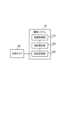
First, the hardware configuration of an
図1に示すように、第1実施形態に係る撮像システム10は、プロセッサ11と、RAM(Random Access Memory)12と、ROM(Read Only Memory)13と、記憶装置14とを備えている。撮像システム10は更に、入力装置15と、出力装置16とを備えていてもよい。プロセッサ11と、RAM12と、ROM13と、記憶装置14と、入力装置15と、出力装置16とは、データバス17を介して接続されている。As shown in Fig. 1, the
プロセッサ11は、コンピュータプログラムを読み込む。例えば、プロセッサ11は、RAM12、ROM13及び記憶装置14のうちの少なくとも一つが記憶しているコンピュータプログラムを読み込むように構成されている。或いは、プロセッサ11は、コンピュータで読み取り可能な記録媒体が記憶しているコンピュータプログラムを、図示しない記録媒体読み取り装置を用いて読み込んでもよい。プロセッサ11は、ネットワークインタフェースを介して、撮像システム10の外部に配置される不図示の装置からコンピュータプログラムを取得してもよい(つまり、読み込んでもよい)。プロセッサ11は、読み込んだコンピュータプログラムを実行することで、RAM12、記憶装置14、入力装置15及び出力装置16を制御する。本実施形態では特に、プロセッサ11が読み込んだコンピュータプログラムを実行すると、プロセッサ11内には、被写体を撮像するための機能ブロックが実現される。また、プロセッサ11として、CPU(Central Processing Unit)、GPU(Graphics Processing Unit)、FPGA(field-programmable gate array)、DSP(Demand-Side Platform)、ASIC(Application Specific Integrated Circuit)のうち一つを用いてもよいし、複数を並列で用いてもよい。The processor 11 reads a computer program. For example, the processor 11 is configured to read a computer program stored in at least one of the
RAM12は、プロセッサ11が実行するコンピュータプログラムを一時的に記憶する。RAM12は、プロセッサ11がコンピュータプログラムを実行している際にプロセッサ11が一時的に使用するデータを一時的に記憶する。RAM12は、例えば、D-RAM(Dynamic RAM)であってもよい。
ROM13は、プロセッサ11が実行するコンピュータプログラムを記憶する。ROM13は、その他に固定的なデータを記憶していてもよい。ROM13は、例えば、P-ROM(Programmable ROM)であってもよい。
記憶装置14は、撮像システム10が長期的に保存するデータを記憶する。記憶装置14は、プロセッサ11の一時記憶装置として動作してもよい。記憶装置14は、例えば、ハードディスク装置、光磁気ディスク装置、SSD(Solid State Drive)及びディスクアレイ装置のうちの少なくとも一つを含んでいてもよい。The
入力装置15は、撮像システム10のユーザからの入力指示を受け取る装置である。入力装置15は、例えば、キーボード、マウス及びタッチパネルのうちの少なくとも一つを含んでいてもよい。The
出力装置16は、撮像システム10に関する情報を外部に対して出力する装置である。例えば、出力装置16は、撮像システム10に関する情報を表示可能な表示装置(例えば、ディスプレイ)であってもよい。The
(機能的構成)
次に、図2を参照しながら、第1実施形態に係る撮像システム10の機能的構成について説明する。図2は、第1実施形態に係る撮像システムの機能的構成を示すブロック図である。 (Functional Configuration)
Next, the functional configuration of the
図2に示すように、第1実施形態に係る撮像システム10は、被写体の虹彩を撮像可能な虹彩カメラ20と接続されている。ただし、撮像システム10は、虹彩カメラ20以外のカメラ(即ち、被写体の虹彩以外の部分を撮像するカメラ)と接続されていてもよい。As shown in Fig. 2, the
撮像システム10は、その機能を実現するための処理ブロックとして、画像取得部110と、動き推定部120と、設定変更部130とを備えている。画像取得部110、動き推定部120、及び設定変更部130は、例えば上述したプロセッサ11(図1参照)において実現されればよい。The
画像取得部110は、虹彩カメラ20で虹彩を撮像しようとする被写体の画像を取得可能に構成されている。なお、画像取得部110の画像取得先は、虹彩カメラ20に限られない。画像取得部110は、被写体を相異なるタイミングで撮像した複数の画像を取得する。画像取得部110で取得された複数の画像は、動き推定部120に出力される構成となっている。The
動き推定部120は、画像取得部110で取得された複数の画像を用いて、被写体の動き(言い換えれば、移動方向)を推定可能に構成されている。なお、複数の画像から被写体の動きを推定する具体的な手法については、既存の技術を適宜採用することができるため、ここでの詳しい説明は省略する。動き推定部120で推定された被写体の動きに関する情報は、設定変更部130に出力される構成となっている。The
設定変更部130は、動き推定部120で推定された被写体の動きに応じて、虹彩カメラ20の設定値を変更可能に構成されている。なお、ここでの「設定値」とは、虹彩カメラ20を撮像画像に影響を与える調整可能なパラメータであり、典型的には虹彩カメラのROI(Region Of Interest)に関する値が一例として挙げられる。設定値は、被写体の動きから算出されてもよいし、予め設定されたマップ等から決定されてもよい。ちなみに、ROIの初期値(即ち、設定変更部130による変更前の値)は、被写体の動き、或いは虹彩カメラ以外のカメラ(例えば、後述する全体俯瞰カメラ30)やセンサ等で取得した被写体の目の高さを元に設定すればよい。The setting
(動作の流れ)
次に、図3を参照しながら、第1実施形態に係る撮像システム10の動作の流れについて説明する。図3は、第1実施形態に係る撮像システムの動作の流れを示すフローチャートである。 (Operation flow)
Next, the flow of operations of the
図3に示すように、第1実施形態に係る撮像システム10が動作する際には、まず画像取得110が、被写体の複数の画像を取得する(ステップS101)。そして、動き推定部120が、複数の画像から被写体の動きを推定する(ステップS102)。As shown in Fig. 3, when the
次に、設定変更部130が、被写体の動きに応じて虹彩カメラ20の設定値を変更する(ステップS103)。この結果、虹彩カメラ20による被写体の撮像は、設定値を変更した状態で実行されることになる。Next, the setting
(技術的効果)
次に、第1実施形態に係る撮像システム10によって得られる技術的効果について説明する。 (Technical effect)
Next, technical effects obtained by the
歩行する被写体は、その歩容に応じて体の各部の位置が変化する。このため、事前に撮像したい部分の位置を特定したとしても、実際の撮像タイミングで撮像したい部分を適切に撮像することは容易ではない。The positions of various parts of a walking subject's body change depending on the subject's gait. For this reason, even if the position of the part to be imaged is specified in advance, it is not easy to properly image the part to be imaged at the actual imaging timing.
図1から図3で説明したように、第1実施形態に係る撮像システム10では、複数の画像から被写体の動きが推定され、推定された動きに応じて虹彩カメラ20の設定値が変更される。よって、被写体の動きを考慮した適切な状態で虹彩カメラ20による撮像を実行できる。1 to 3, in the
<変形例>
以下、第1実施形態の変形例について、図4から図6を参照して説明する。なお、図4から図6では、図2で示した構成要素と同様のものに同一の符号を付している。下記変形例は、それぞれ組み合わせることも可能である。また、後述する第2実施形態以降の実施形態にも適用可能である。 <Modification>
Modifications of the first embodiment will be described below with reference to Figures 4 to 6. In Figures 4 to 6, the same components as those shown in Figure 2 are denoted by the same reference numerals. The following modifications can be combined with each other. They can also be applied to the second and subsequent embodiments described later.
(第1変形例)
まず、図4を参照して第1変形例について説明する。図4は、第1変形例に係る撮像システムの機能的構成を示すブロック図である。 (First Modification)
First, the first modified example will be described with reference to Fig. 4. Fig. 4 is a block diagram showing the functional configuration of an imaging system according to the first modified example.
図4に示すように、画像取得部110は、虹彩カメラ20から複数の画像を取得するように構成されてもよい。この場合、虹彩カメラ20では、まず被写体の動きを推定するための複数の画像が撮像され、その後、被写体の動きに応じて設定値が変更されてから被写体の虹彩画像が撮像されることになる。第1変形例では、虹彩カメラ20以外のカメラを必要としないため、システムの複雑化やコストの増大を抑制することが可能である。As shown in FIG. 4, the
(第2変形例)
次に、図5を参照して第2変形例について説明する。図5は、第2変形例に係る撮像システムの機能的構成を示すブロック図である。 (Second Modification)
Next, a second modified example will be described with reference to Fig. 5. Fig. 5 is a block diagram showing the functional configuration of an imaging system according to the second modified example.
図5に示すように、画像取得部110は、全体俯瞰カメラ30から複数の画像を取得するように構成されてもよい。全体俯瞰カメラ30は、虹彩カメラ20のより撮像範囲(即ち、画角)が広いカメラとして構成されている。第2変形例では、例えば被写体の全体が写った画像から被写体の動きを推定することができる。よって、虹彩カメラ20のみで被写体の動きを推定する場合(即ち、第1変形例)と比較すると、より柔軟に被写体の動きを推定することが可能となる。As shown in FIG. 5, the
(第3変形例)
次に、図6を参照して第3変形例について説明する。図6は、第3変形例に係る撮像システムの機能的構成を示すブロック図である。 (Third Modification)
Next, a third modified example will be described with reference to Fig. 6. Fig. 6 is a block diagram showing the functional configuration of an imaging system according to the third modified example.
図6に示すように、撮像システム10は、図1の構成に加えて認証処理部140を更に備えて構成されてもよい。認証処理部140は、虹彩カメラ20で撮像された画像を用いて虹彩認証(即ち、生体認証)を実行可能に構成されている。ここで特に、虹彩カメラ20で撮像される虹彩画像は、上述したように被写体の動きを考慮した状態で撮像される。従って、虹彩認証の精度を高めることが可能である。なお、認証処理部140は、例えば上述したプロセッサ11(図1参照)において実現されればよい。或いは、認証処理部140は、撮像システム10の外部(例えば、外部サーバやクラウド等)に設けられていてもよい。As shown in FIG. 6, the
<第2実施形態>
第2実施形態に係る撮像システム10について、図7及び図8を参照して説明する。なお、第2実施形態は、上述した第1実施形態における設定値の変更の具体例を説明するものであり、その構成や動作の流れは第1実施形態(図1から図3参照)と同一であってよい。このため、以下では、第1実施形態と重複する部分については適宜説明を省略するものとする。 Second Embodiment
The
(歩容による頭の上下動作)
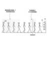
まず、図7を参照して、歩容による被写体の頭の上下動作について説明する。図7は、歩容による被写体の頭の上下動作を示す概念図である。 (Head up and down movement with gait)
First, the up and down movement of the subject's head due to gait will be described with reference to Fig. 7. Fig. 7 is a conceptual diagram showing the up and down movement of the subject's head due to gait.
図7に示すように、歩行する被写体500は、その歩容により頭が上下に動く。このため、虹彩カメラ20で被写体500の虹彩を撮像しようとする場合、歩容により虹彩位置(即ち、目位置)が移動し続けることになり、適切な画像を撮像することは容易ではない。特に、虹彩カメラ20では、高精細な画像を撮像して高速通信を行うことが要求されるため、その撮像範囲は比較的狭く設定されることが多い。よって、虹彩カメラ20の撮像範囲(即ち、ROI)内に被写体500の虹彩を正確に収めることは容易ではない。As shown in Figure 7, the head of a walking subject 500 moves up and down depending on the subject's gait. Therefore, when attempting to capture an image of the iris of subject 500 using
これに対し、第2実施形態に係る撮像システム10では、被写体500の動きに応じてROIを移動させることで、被写体500の虹彩画像を撮像する。即ち、第2実施形態では、虹彩カメラ20の設定値として、虹彩カメラ20のROIを変更する。より具体的には、虹彩カメラ20の合焦地点において、被写体500の目(即ち、特定部分)が虹彩カメラのROI内に含まれるように制御する。In contrast, in the
次に、図8を参照して、虹彩カメラのROIを変更する方法について説明する。図8は、被写体の動きに合わせて虹彩カメラのROIを移動させる方法の一例を示す概念図である。Next, a method for changing the ROI of the iris camera will be described with reference to Fig. 8. Fig. 8 is a conceptual diagram showing an example of a method for moving the ROI of the iris camera in accordance with the movement of the subject.
図8に示すように、仮にROIが固定であったとすると、虹彩カメラ20の合焦地点直前においてROI内に被写体の目位置が含まれていた場合でも、その直後の合焦地点においては、被写体の目位置がROIの外に出てしまうおそれがある。よって、合焦地点直前において正確に目位置を推定できたとしても、合焦地点において目位置をROI内に収めることは難しい。8, if the ROI were fixed, even if the subject's eye position was included within the ROI immediately before the focusing point of the
しかるに第2実施形態に係る撮像システム10では、被写体500の動きに応じて虹彩カメラ20のROIを移動させる。例えば、図に示す例では、被写体500が撮像範囲の上側に移動していることが分かる。この場合、設定変更部130は、虹彩カメラ20のROIを上側に移動するように変更する。この結果、虹彩カメラ20の合焦地点において、被写体500の目が虹彩カメラのROI内に含まれることになる。なお、ROIの移動は、虹彩カメラ20の読み込み画素を変更することで移動されてもよいし、虹彩カメラ20そのものを移動させてもよい。虹彩カメラ20そのものを移動させる場合には、虹彩カメラ20本体角をパンチルトさせてもよいし、虹彩カメラ20本体を上下左右に移動させてもよいし、虹彩カメラ20の光軸に合わせた稼働ミラーをパンチルトさせてもよいし、これらを組み合わせてもよい。或いは、撮像範囲の異なる複数の虹彩カメラを用意しておき、撮像に利用する虹彩カメラ20を適宜選択するようにしてもよい。However, in the
(技術的効果)
次に、第2実施形態に係る撮像システム10によって得られる技術的効果について説明する。 (Technical effect)
Next, technical effects obtained by the
図7及び図8で説明したように、第2実施形態に係る撮像システム10では、被写体500の動きに合わせてROIが移動される。従って、被写体500が動いている場合であっても、その虹彩を適切に撮像することが可能である。なお、上述した例では、被写体500が上下に動く場合を例に挙げたが、被写体が左右方向、或いは斜め方向に移動する場合であっても、その方向にROIを移動させることで適切な撮像を実現することができる。7 and 8, in the
<第3実施形態>
第3実施形態に係る撮像システム10について、図9から図11を参照して説明する。なお、第3実施形態は、上述した第1及び第2実施形態と比べて一部の動作が異なるのみで、その構成については第1実施形態(図1及び図2参照)、或いはその変形例(図4から図6参照)と同一であってよい。このため、以下では、すでに説明した部分と重複する部分については適宜説明を省略するものとする。 Third Embodiment
The
(動作の流れ)
まず、図9を参照しながら、第3実施形態に係る撮像システム10の動作の流れについて説明する。図9は、第3実施形態に係る撮像システムの動作の流れを示すフローチャートである。なお、図9では、図3に示した処理と同様の処理に同一の符号を付している。 (Operation flow)
First, the flow of operations of the
図9に示すように、第3実施形態に係る撮像システム10が動作する際には、まず画像取得110が、被写体500の複数の画像を取得する(ステップS101)。そして第3実施形態では特に、動き推定部120が、複数の画像の差分を用いて被写体500の動きを推定する(ステップS201)。As shown in Fig. 9, when the
次に、設定変更部130が、被写体500の動きに応じて虹彩カメラ20の設定値を変更する(ステップS103)。その後、撮像が終了したと判定された場合(ステップS202:YES)、一連の動作は終了することになる。なお、撮像が終了したか否かは、予め設定された撮像枚数が撮像されたか否かによって判定してもよい。Next, the setting
一方、撮像が終了したと判定されない場合(ステップS202:NO)、ステップS101から処理が繰り返し実行される。よって、第3実施形態では、虹彩カメラ20による虹彩画像の撮像が終了するまで、虹彩カメラ20の設定値変更が逐次実行されることになる。On the other hand, if it is not determined that the image capture is completed (step S202: NO), the process is repeated from step S101. Therefore, in the third embodiment, the setting value of the
(具体的な推定方法)
次に、図10及び図11を参照して、画像差分を用いて被写体500の動きを推定する方法の具体例について説明する。図10は、オプティカルフローを利用して被写体の移動方向を算出する方法の一例を示す概念図である。図11は、目位置の変動から被写体の移動方向を算出する方法の一例を示す概念図である。 (Specific estimation method)
Next, a specific example of a method for estimating the movement of the subject 500 using image differences will be described with reference to Fig. 10 and Fig. 11. Fig. 10 is a conceptual diagram showing an example of a method for calculating the movement direction of the subject using optical flow. Fig. 11 is a conceptual diagram showing an example of a method for calculating the movement direction of the subject from the change in eye position.
図10に示すように、第3実施形態に係る撮像システム10では、オプティカルフローを用いて被写体500の動きが推定されてもよい。具体的には、動き推定部120は、虹彩カメラ20で、合焦地点直前(1)のタイミングで撮像された画像と、その直後の合焦地点直前(2)で撮像された画像とから、オプティカルフローを算出する。そして、設定値変更部130は、算出されたオプティカルフローに基づいて、虹彩カメラ20のROIを移動させる。この結果、合焦地点直前(2)の直後である合焦地点直前(3)においては、ROIが上側(即ち、オプティカルフローの方向)に移動された状態で虹彩画像の撮像が実行されることになる。10, in the
図11に示すように、第3実施形態に係る撮像システム10では、被写体500の目位置を検出して被写体500の動きが推定されてもよい。具体的には、動き推定部120は、全体俯瞰カメラ30で、合焦地点直前(1)のタイミングで撮像された画像と、その直後の合焦地点直前(2)で撮像された画像とから、それぞれ被写体500の目位置を検出する。なお、目位置の検出には、既存の技術を適宜採用することができる。動き推定部120は、2つの画像の目位置の差分から、被写体500の目位置の変動方向を算出する。その後、設定値変更部130は、算出された目位置の変動方向に基づいて、虹彩カメラ20のROIを移動させる。この結果、合焦地点直前(2)の直後である合焦地点直前(3)においては、ROIが上側(即ち、目位置の変動方向)に移動された状態で虹彩画像の撮像が実行されることになる。As shown in FIG. 11, in the
(技術的効果)
次に、第3実施形態に係る撮像システム10によって得られる技術的効果について説明する。 (Technical effect)
Next, technical effects obtained by the
図9から図11で説明したように、第3実施形態に係る撮像システム10では、複数の画像の差分から被写体500の動きが推定され、虹彩カメラ20のROI(即ち、設定値)が変更される。このようにすれば、被写体500の動きに合わせて逐次虹彩カメラ20の設定値が変更されることになるため、より適切に被写体500の画像を撮像することが可能である。9 to 11, in the
<第4実施形態>
第4実施形態に係る撮像システム10について、図12及び図13を参照して説明する。
なお、第4実施形態は、上述した第1から第3実施形態と比べて一部の動作が異なるのみで、その構成については第1実施形態(図1及び図2参照)、或いはその変形例(図4から図6参照)と同一であってよい。このため、以下では、すでに説明した部分と重複する部分については適宜説明を省略するものとする。 Fourth Embodiment
An
The fourth embodiment differs from the first to third embodiments in some operations, and may have the same configuration as the first embodiment (see FIGS. 1 and 2) or its modified examples (see FIGS. 4 to 6). Therefore, in the following, descriptions of parts that overlap with those already described will be omitted as appropriate.
(動作の流れ)
まず、図12を参照しながら、第4実施形態に係る撮像システム10の動作の流れについて説明する。図12は、第4実施形態に係る撮像システムの動作の流れを示すフローチャートである。なお、図12では、図3に示した処理と同様の処理に同一の符号を付している。 (Operation flow)
First, the flow of operations of the
図12に示すように、第4実施形態に係る撮像システム10が動作する際には、まず画像取得110が、被写体の複数の画像を取得する(ステップS101)。そして第4実施形態では特に、動き推定部120が、複数の画像から被写体500の歩容周期を推定する(ステップS301)。なお、複数の画像を用いた歩容周期の推定方法については、既存の技術を適宜採用することが可能である。12, when the
次に、設定変更部130が、被写体500の歩容周期に応じて虹彩カメラ20のROIを周期振動させる(ステップS302)。このため、虹彩カメラ20のROIは、被写体500の歩容周期に合わせて変動し続けることになる。なお、被写体500の歩容周期は、典型的に上下動作であるが(図7参照)、例えば左右方向、或いは斜め方向の動作であってもよい。Next, the setting
(具体的な動作例)
次に、図13を参照して、第4実施形態に係る撮像システム10のより具体的な動作例について説明する。図13は、被写体の歩容周期を推定してROIを周期振動させる方法の一例を示す概念図である。 (Specific operation example)
Next, a more specific operation example of the
図13に示すように、第4実施形態に係る撮像システム10では、虹彩カメラの合焦地点よりも手前にあるエリアにおいて、複数の画像が撮像され被写体500の歩容周期が推定される。なお、歩容周期を推定するエリアは予め設定しておけばよく、例えば各種センサ等を配置しておくことで、被写体500が歩容周期を推定するエリアに進入したことを検出できる。13, in the
その後、被写体500が虹彩カメラ20の合焦地点の周辺(言い換えれば、虹彩カメラ20で虹彩画像を撮像するエリア)に到達すると、虹彩カメラ20のROIが推定した歩容周期に応じて周期振動される。虹彩カメラ20のROIは、典型的には虹彩画像20の撮像処理(例えば、所定枚数の撮像)が完了するまで振動され続ける。Thereafter, when the subject 500 reaches the vicinity of the focal point of the iris camera 20 (in other words, the area where the iris image is captured by the iris camera 20), the ROI of the
(技術的効果)
次に、第4実施形態に係る撮像システム10によって得られる技術的効果について説明する。 (Technical effect)
Next, technical effects obtained by the
図12及び図13で説明したように、第4実施形態に係る撮像システム10では、複数の画像から被写体500の歩容周期が推定され、その歩容周期に合わせて虹彩カメラ20のROI(即ち、設定値)が変更される。このようにすれば、被写体500の動きを追従するように虹彩カメラ20のROIが移動されるため、より適切に被写体500の虹彩画像を撮像することが可能である。また、第4実施形態に係る撮像システム10は、上述した第3実施形態(即ち、画像差分から被写体500の動きを推定する場合)と比較して、被写体の動きを推定する際の処理負荷が小さい。よって、処理時間を短縮することができ、合焦地点付近における虹彩画像撮像時のフレームレートを高速に維持することができる。従って、よりよく合焦した虹彩画像を撮像することが可能である。12 and 13, in the
<第5実施形態>
第5実施形態に係る撮像システム10について、図14を参照して説明する。なお、第5実施形態は、上述した第3及び第4実施形態を組み合わせたものであり、その構成については第1実施形態(図1及び図2参照)、或いはその変形例(図4から図6参照)と同一であってよい。このため、以下では、すでに説明した部分と重複する部分については適宜説明を省略するものとする。 Fifth Embodiment
An
(動作の流れ)
まず、図14を参照しながら、第5実施形態に係る撮像システム10の動作の流れについて説明する。図14は、第5実施形態に係る撮像システムの動作の流れを示すフローチャートである。なお、図14では、図9及び図12に示した処理と同様の処理に同一の符号を付している。 (Operation flow)
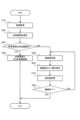
First, the flow of operations of the
図14に示すように、第5実施形態に係る撮像システム10が動作する際には、まず画像取得110が、被写体の複数の画像を取得する(ステップS101)。そして、動き推定部120が、複数の画像から被写体500の歩容周期を推定する(ステップS301)。14, when the
ここで特に、第5実施形態に係る撮像システム10は、推定した歩容周期が所定範囲内であるか否かを判定する(ステップS401)。なお、ここでの「所定範囲」とは、歩容周期を用いたROIの周期振動(即ち、上述した第4実施形態の動作)を実現可能かを判定するための閾値であり、例えば想定される一般的な歩容周期が所定範囲内となる一方で、怪我している人や、足が不自由な人等の不規則な歩容については所定範囲外となるように設定される。Here, in particular, the
歩容周期が所定範囲内であると判定された場合(ステップS401:YES)、設定変更部130が、被写体500の歩容周期に応じて虹彩カメラ20のROIを周期振動させる(ステップS302)。即ち、第4実施形態と同様の動作が実現される(図12及び図13等を参照)。If it is determined that the gait cycle is within the predetermined range (step S401: YES), the setting
一方、歩容周期が所定範囲内でないと判定された場合(ステップS401:NO)、画像取得部110が被写体の画像を再取得し(ステップS402)、動き推定部120が、複数の画像の差分を用いて被写体500の動きを推定する(ステップS201)。そして、設定変更部130が、被写体500の動きに応じて虹彩カメラ20の設定値を変更する(ステップS103)。その後、撮像が終了したと判定された場合(ステップS202:YES)、一連の動作は終了する一方で、撮像が終了したと判定されない場合(ステップS202:NO)、ステップS401から処理が繰り返し実行される。即ち、第3実施形態と同様の動作が実現される(図9から図11等を参照)。On the other hand, if it is determined that the gait cycle is not within the predetermined range (step S401: NO), the
(技術的効果)
次に、第5実施形態に係る撮像システム10によって得られる技術的効果について説明する。 (Technical effect)
Next, technical effects obtained by the
図14で説明したように、第5実施形態に係る撮像システム10では、歩容周期が所定範囲内である場合に、歩容周期に応じてROIが周期振動される。このため、第4実施形態と同様に、比較的小さい処理負荷で被写体500の動きを推定できる。一方、歩容周期が所定範囲内でない場合には、画像差分を用いてROIが変更される。よって、歩容周期によって被写体の動きを推定することが難しい場合にも、確実に被写体の動きを推定し、適切にROIを変更することができる。As described in FIG. 14, in the
<付記>
以上説明した実施形態に関して、更に以下の付記のようにも記載されうるが、以下には限られない。 <Additional Notes>
The above-described embodiment may be further described as follows, but is not limited to the following.
(付記1)
付記1に記載の撮像システムは、被写体を相異なるタイミングで撮像した複数の画像を取得する取得手段と、前記複数の画像に基づいて、前記被写体の動きを推定する推定手段と、前記被写体の動きに応じて、前記被写体の特定部分を撮像する撮像部の設定値を変更する変更手段とを備えることを特徴とする撮像システムである。 (Appendix 1)
The imaging system described in Appendix 1 is an imaging system characterized by comprising an acquisition means for acquiring a plurality of images of a subject captured at different times, an estimation means for estimating the movement of the subject based on the plurality of images, and a change means for changing a setting value of an imaging unit that captures an image of a specific part of the subject in accordance with the movement of the subject.
(付記2)
付記2に記載の撮像システムは、前記変更手段は、前記撮像部の合焦地点において前記特定部分が前記撮像部の撮像範囲に含まれるように前記設定値を変更することを特徴とする付記1に記載の撮像システムである。 (Appendix 2)
The imaging system described in Supplementary Note 2 is the imaging system described in Supplementary Note 1, characterized in that the change means changes the setting value so that the specific portion is included in the imaging range of the imaging unit at the focus point of the imaging unit.
(付記3)
付記3に記載の撮像システムは、前記推定手段は、前記複数の画像の差分から前記被写体の動きを推定することを特徴とする付記1又は2に記載の撮像システムである。 (Appendix 3)
The imaging system according to claim 3 is the imaging system according to claim 1 or 2, wherein the estimation means estimates the movement of the subject from a difference between the plurality of images.
(付記4)
前記推定手段は、前記複数の画像から前記被写体の歩容周期を推定することで、前記被写体の動きを推定することを特徴とする付記1又は2に記載の撮像システムである。 (Appendix 4)
The imaging system according to claim 1 or 2, wherein the estimation means estimates a gait cycle of the subject from the plurality of images to estimate a movement of the subject.
(付記5)
付記5に記載の撮像システムは、前記推定手段は、前記歩容周期が所定範囲内でない場合に、前記複数の画像の差分から前記被写体の動きを推定することを特徴とする付記4に記載の撮像システムである。 (Appendix 5)
The imaging system described in Supplementary Note 5 is the imaging system described in Supplementary Note 4, characterized in that the estimation means estimates the movement of the subject from a difference between the multiple images when the gait cycle is not within a predetermined range.
(付記6)
付記6に記載の撮像システムは、前記取得手段は、前記撮像部から前記複数の画像を取得することを特徴とする付記1から5のいずれか一項に記載の撮像システムである。 (Appendix 6)
The imaging system described in Supplementary Note 6 is the imaging system described in any one of Supplementary Notes 1 to 5, characterized in that the acquisition means acquires the plurality of images from the imaging section.
(付記7)
付記7に記載の撮像システムは、前記取得手段は、前記撮像部とは異なる第2の撮像部から前記複数の画像を取得することを特徴とする付記1から5のいずれか一項に記載の撮像システムである。 (Appendix 7)
The imaging system described in Supplementary Note 7 is the imaging system described in any one of Supplementary Notes 1 to 5, characterized in that the acquisition means acquires the multiple images from a second imaging unit different from the imaging unit.
(付記8)
付記8に記載の撮像システムは、前記撮像部が撮像した前記特定部分の画像を用いて、前記被写体の認証処理を実行する認証手段を更に備えることを特徴とする付記1から7のいずれか一項に記載の撮像システムである。 (Appendix 8)
The imaging system described in Appendix 8 is the imaging system described in any one of Appendixes 1 to 7, further comprising an authentication means for performing authentication processing of the subject using an image of the specific part captured by the imaging unit.
(付記9)
付記9に記載の撮像方法は、被写体を相異なるタイミングで撮像した複数の画像を取得し、
前記複数の画像に基づいて、前記被写体の動きを推定し、前記被写体の動きに応じて、前記被写体の特定部分を撮像する撮像部の設定値を変更することを特徴とする撮像方法である。 (Appendix 9)
The imaging method according to claim 9 further comprises acquiring a plurality of images of a subject captured at different times,
The imaging method is characterized in that the movement of the subject is estimated based on the plurality of images, and a setting value of an imaging section that captures an image of a specific portion of the subject is changed in accordance with the movement of the subject.
(付記10)
付記10に記載のコンピュータプログラムは、被写体を相異なるタイミングで撮像した複数の画像を取得し、前記複数の画像に基づいて、前記被写体の動きを推定し、前記被写体の動きに応じて、前記被写体の特定部分を撮像する撮像部の設定値を変更するようにコンピュータを動作させることを特徴とするコンピュータプログラムである。 (Appendix 10)
The computer program described in
この開示は、請求の範囲及び明細書全体から読み取ることのできる発明の要旨又は思想に反しない範囲で適宜変更可能であり、そのような変更を伴う撮像システム、撮像方法、及びコンピュータプログラムもまたこの開示の技術思想に含まれる。This disclosure may be modified as appropriate without departing from the spirit or concept of the invention as can be read from the claims and the entire specification, and imaging systems, imaging methods, and computer programs incorporating such modifications are also included in the technical concept of this disclosure.
10 撮像システム
20 虹彩カメラ
30 全体俯瞰カメラ
110 画像取得部
120 動き推定部
130 設定変更部
140 認証処理部
500 被写体 REFERENCE SIGNS
Claims (11)
Translated fromJapanese前記複数の画像に基づいて、前記被写体の動きを推定する推定手段と、
前記被写体の虹彩を撮像する撮像部の設定値を変更する変更手段と
を備え、
前記変更手段は、前記撮像部の合焦地点において前記被写体の虹彩が、固定された前記撮像部の撮像範囲に含まれるように、前記被写体の動きに応じて、前記撮像部の合焦地点におけるROI(Region Of Interest)を変更することを特徴とする撮像システム。 An acquisition means for acquiring a plurality of images of a subject captured at different times;
an estimation means for estimating a movement of the subject based on the plurality of images;
and a change unit for changing a setting value of an imaging unit for capturing an image of the iris of the subject,
the change meanschanges a Region Of Interest (ROI) at a focus point of the imaging unit in response to a movement of the subject so that an iris of the subject is included in a fixed imaging range of the imaging unit at the focus point of the imaging unit.
前記変更手段は、前記撮像部の合焦地点において前記被写体の虹彩が前記撮像部の撮像範囲に含まれるように、前記ROIを変更することを特徴とする請求項1に記載の撮像システム。 The estimation means estimates a movement of the subject based on the plurality of images captured of the subject before the focusing point,
2. The imaging system according to claim 1, wherein the change unit changes the ROI so that an iris of the subject is included in an imaging range of the imaging unit at a focus point of the imaging unit.
前記複数の画像に基づいて、前記被写体の動きを推定し、
前記被写体の虹彩を撮像する撮像部の合焦地点において前記被写体の虹彩が、固定された前記撮像部の撮像範囲に含まれるように、前記被写体の動きに応じて、前記撮像部の合焦地点におけるROIを変更する
ことを特徴とする撮像方法。 Acquire multiple images of the subject captured at different times,
Estimating a movement of the subject based on the plurality of images;
an ROI at a focus point of an imaging unit that captures an iris of the subject is changed in response to a movement of the subject so that the iris of the subject is included in a fixed imaging range of the imaging unit at the focus point ofthe imaging unit that captures the iris of the subject .
前記複数の画像に基づいて、前記被写体の動きを推定し、
前記被写体の虹彩を撮像する撮像部の合焦地点において前記被写体の虹彩が、固定された前記撮像部の撮像範囲に含まれるように、前記被写体の動きに応じて、前記撮像部の合焦地点におけるROIを変更する
ようにコンピュータを動作させることを特徴とするコンピュータプログラム。 Acquire multiple images of the subject captured at different times,
Estimating a movement of the subject based on the plurality of images;
A computer program that causes a computer to operate in such a way that an ROI at a focus point of an imaging unit that captures an iris of the subject is changed in response to a movement of the subject so that the iris of the subject is included in a fixed imaging range of the imaging unit at the focus point ofthe imaging unit.
Applications Claiming Priority (1)
| Application Number | Priority Date | Filing Date | Title |
|---|---|---|---|
| PCT/JP2020/019310WO2021229761A1 (en) | 2020-05-14 | 2020-05-14 | Image-capturing system, image-capturing method, and computer program |
Publications (2)
| Publication Number | Publication Date |
|---|---|
| JPWO2021229761A1 JPWO2021229761A1 (en) | 2021-11-18 |
| JP7468637B2true JP7468637B2 (en) | 2024-04-16 |
Family
ID=78525570
Family Applications (1)
| Application Number | Title | Priority Date | Filing Date |
|---|---|---|---|
| JP2022522444AActiveJP7468637B2 (en) | 2020-05-14 | 2020-05-14 | Imaging system, imaging method, and computer program |
Country Status (3)
| Country | Link |
|---|---|
| US (1) | US20230171500A1 (en) |
| JP (1) | JP7468637B2 (en) |
| WO (1) | WO2021229761A1 (en) |
Families Citing this family (5)
| Publication number | Priority date | Publication date | Assignee | Title |
|---|---|---|---|---|
| JP7371712B2 (en)* | 2021-12-28 | 2023-10-31 | 日本電気株式会社 | Imaging system, imaging method, and computer program |
| JP7371762B1 (en)* | 2021-12-28 | 2023-10-31 | 日本電気株式会社 | Imaging system, imaging device, imaging method, and recording medium |
| WO2024154223A1 (en)* | 2023-01-17 | 2024-07-25 | 日本電気株式会社 | Information processing device, information processing method, and recording medium |
| WO2024171297A1 (en)* | 2023-02-14 | 2024-08-22 | 日本電気株式会社 | Information processing device, information processing method, and recording medium |
| JPWO2024195115A1 (en)* | 2023-03-23 | 2024-09-26 |
Citations (4)
| Publication number | Priority date | Publication date | Assignee | Title |
|---|---|---|---|---|
| JP2006163683A (en) | 2004-12-06 | 2006-06-22 | Matsushita Electric Ind Co Ltd | Eye image photographing device and authentication device using the same |
| JP2010154391A (en) | 2008-12-26 | 2010-07-08 | Panasonic Corp | Automatic tracking camera apparatus |
| JP2019192969A (en) | 2018-04-18 | 2019-10-31 | ミネベアミツミ株式会社 | Imaging apparatus, imaging system, and street light |
| WO2020065852A1 (en) | 2018-09-27 | 2020-04-02 | 日本電気株式会社 | Authentication system, authentication method, and storage medium |
Family Cites Families (2)
| Publication number | Priority date | Publication date | Assignee | Title |
|---|---|---|---|---|
| WO2017029718A1 (en)* | 2015-08-19 | 2017-02-23 | 株式会社 テクノミライ | Smart-security digital system, method and program |
| US10282720B1 (en)* | 2018-07-16 | 2019-05-07 | Accel Robotics Corporation | Camera-based authorization extension system |
- 2020
- 2020-05-14JPJP2022522444Apatent/JP7468637B2/enactiveActive
- 2020-05-14WOPCT/JP2020/019310patent/WO2021229761A1/ennot_activeCeased
- 2020-05-14USUS17/922,634patent/US20230171500A1/ennot_activeAbandoned
Patent Citations (4)
| Publication number | Priority date | Publication date | Assignee | Title |
|---|---|---|---|---|
| JP2006163683A (en) | 2004-12-06 | 2006-06-22 | Matsushita Electric Ind Co Ltd | Eye image photographing device and authentication device using the same |
| JP2010154391A (en) | 2008-12-26 | 2010-07-08 | Panasonic Corp | Automatic tracking camera apparatus |
| JP2019192969A (en) | 2018-04-18 | 2019-10-31 | ミネベアミツミ株式会社 | Imaging apparatus, imaging system, and street light |
| WO2020065852A1 (en) | 2018-09-27 | 2020-04-02 | 日本電気株式会社 | Authentication system, authentication method, and storage medium |
Non-Patent Citations (1)
| Title |
|---|
| 大阪大学,第1部 モダリティ別の技術動向,生体認証技術の動向と活用:科学技術に関す る調査プロジェクト,日本,国立国会図書館,2019年03月29日,26-27頁 |
Also Published As
| Publication number | Publication date |
|---|---|
| US20230171500A1 (en) | 2023-06-01 |
| WO2021229761A1 (en) | 2021-11-18 |
| JPWO2021229761A1 (en) | 2021-11-18 |
Similar Documents
| Publication | Publication Date | Title |
|---|---|---|
| JP7468637B2 (en) | Imaging system, imaging method, and computer program | |
| US8068639B2 (en) | Image pickup apparatus, control method therefor, and computer program for detecting image blur according to movement speed and change in size of face area | |
| CN102959586B (en) | Depth estimation device and depth estimation method | |
| JP5794705B2 (en) | Imaging apparatus, control method thereof, and program | |
| CN106954007B (en) | Camera device and camera method | |
| JP6325615B2 (en) | Method and apparatus for setting camera focus. | |
| JPWO2008117584A1 (en) | Camera shake correction apparatus, imaging apparatus, camera shake correction program, imaging program, camera shake correction method, and imaging method | |
| JP2012175207A (en) | Image processing apparatus, image processing method, and computer program | |
| CN106303249B (en) | Video stabilization method and device | |
| JP2025013835A (en) | Gaze estimation system, gaze estimation method, and computer program | |
| JP2023100678A (en) | Iris authentication device, iris authentication method, computer program and recording medium | |
| JP7401246B2 (en) | Imaging device, method of controlling the imaging device, and program | |
| CN112714900A (en) | Display screen operation method, electronic device and readable storage medium | |
| CN106454066B (en) | Image processing apparatus and control method thereof | |
| JP2015191074A (en) | Imaging device | |
| JP2019057240A (en) | Imaging apparatus | |
| WO2022176323A1 (en) | Biometric authentication system, biometric authentication method, and recording medium | |
| JP2017038243A (en) | Imaging device | |
| WO2024171297A1 (en) | Information processing device, information processing method, and recording medium | |
| JP2015102602A (en) | Stereoscopic imaging device, stereoscopic imaging system, control method of stereoscopic imaging device, program, and storage medium | |
| JP7743189B2 (en) | Image processing device and control method thereof, and imaging device | |
| JP7693370B2 (en) | Imaging control device, imaging control method and program | |
| JP5973806B2 (en) | IMAGING DEVICE, IMAGING DEVICE CONTROL METHOD, AND PROGRAM | |
| US20240314431A1 (en) | Apparatus, capturing apparatus, method for apparatus | |
| JP2014216694A (en) | Tracking pan head device with resolution increase processing |
Legal Events
| Date | Code | Title | Description |
|---|---|---|---|
| A621 | Written request for application examination | Free format text:JAPANESE INTERMEDIATE CODE: A621 Effective date:20221102 | |
| A131 | Notification of reasons for refusal | Free format text:JAPANESE INTERMEDIATE CODE: A131 Effective date:20230509 | |
| A521 | Request for written amendment filed | Free format text:JAPANESE INTERMEDIATE CODE: A523 Effective date:20230628 | |
| A131 | Notification of reasons for refusal | Free format text:JAPANESE INTERMEDIATE CODE: A131 Effective date:20231003 | |
| A521 | Request for written amendment filed | Free format text:JAPANESE INTERMEDIATE CODE: A523 Effective date:20231128 | |
| TRDD | Decision of grant or rejection written | ||
| A01 | Written decision to grant a patent or to grant a registration (utility model) | Free format text:JAPANESE INTERMEDIATE CODE: A01 Effective date:20240305 | |
| A61 | First payment of annual fees (during grant procedure) | Free format text:JAPANESE INTERMEDIATE CODE: A61 Effective date:20240318 | |
| R150 | Certificate of patent or registration of utility model | Ref document number:7468637 Country of ref document:JP Free format text:JAPANESE INTERMEDIATE CODE: R150 |