JP7467070B2 - Electrodes on a double-sided printed circuit board (PCB) for canceling far-field signals - Google Patents
Electrodes on a double-sided printed circuit board (PCB) for canceling far-field signalsDownload PDFInfo
- Publication number
- JP7467070B2 JP7467070B2JP2019193268AJP2019193268AJP7467070B2JP 7467070 B2JP7467070 B2JP 7467070B2JP 2019193268 AJP2019193268 AJP 2019193268AJP 2019193268 AJP2019193268 AJP 2019193268AJP 7467070 B2JP7467070 B2JP 7467070B2
- Authority
- JP
- Japan
- Prior art keywords
- diagnostic
- electrodes
- expandable
- signals
- electrode
- Prior art date
- Legal status (The legal status is an assumption and is not a legal conclusion. Google has not performed a legal analysis and makes no representation as to the accuracy of the status listed.)
- Active
Links
- 210000004369bloodAnatomy0.000claimsdescription16
- 239000008280bloodSubstances0.000claimsdescription16
- 210000000056organAnatomy0.000claimsdescription12
- 230000002452interceptive effectEffects0.000claimsdescription9
- 230000017531blood circulationEffects0.000claimsdescription6
- 238000003780insertionMethods0.000claimsdescription4
- 230000037431insertionEffects0.000claimsdescription4
- 210000001519tissueAnatomy0.000description41
- 238000000034methodMethods0.000description16
- 239000000758substrateSubstances0.000description8
- 210000005003heart tissueAnatomy0.000description7
- 239000012528membraneSubstances0.000description7
- 230000000747cardiac effectEffects0.000description6
- 230000000694effectsEffects0.000description6
- 238000002679ablationMethods0.000description5
- 238000004891communicationMethods0.000description4
- 238000013461designMethods0.000description4
- 208000007536ThrombosisDiseases0.000description3
- 230000004913activationEffects0.000description3
- 230000001746atrial effectEffects0.000description3
- 239000000523sampleSubstances0.000description3
- 239000012620biological materialSubstances0.000description2
- 230000015572biosynthetic processEffects0.000description2
- 230000035602clottingEffects0.000description2
- 238000001514detection methodMethods0.000description2
- 238000010586diagramMethods0.000description2
- 230000006870functionEffects0.000description2
- 238000009413insulationMethods0.000description2
- 229920000139polyethylene terephthalatePolymers0.000description2
- 239000005020polyethylene terephthalateSubstances0.000description2
- 230000008569processEffects0.000description2
- 210000003492pulmonary veinAnatomy0.000description2
- 239000000565sealantSubstances0.000description2
- VHGHHZZTMJLTJX-UHFFFAOYSA-N1,2,4-trichloro-3-(2-chlorophenyl)benzeneChemical compoundClC1=CC=C(Cl)C(C=2C(=CC=CC=2)Cl)=C1ClVHGHHZZTMJLTJX-UHFFFAOYSA-N0.000description1
- 206010003658Atrial FibrillationDiseases0.000description1
- 206010061218InflammationDiseases0.000description1
- 229920002614Polyether block amidePolymers0.000description1
- 230000002159abnormal effectEffects0.000description1
- 239000000853adhesiveSubstances0.000description1
- 230000001070adhesive effectEffects0.000description1
- 206010003119arrhythmiaDiseases0.000description1
- 230000006793arrhythmiaEffects0.000description1
- 239000000560biocompatible materialSubstances0.000description1
- 238000004364calculation methodMethods0.000description1
- 210000005242cardiac chamberAnatomy0.000description1
- 230000008859changeEffects0.000description1
- 238000009429electrical wiringMethods0.000description1
- 239000003822epoxy resinSubstances0.000description1
- 210000002837heart atriumAnatomy0.000description1
- 230000004054inflammatory processEffects0.000description1
- 208000014674injuryDiseases0.000description1
- 239000011810insulating materialSubstances0.000description1
- 210000005246left atriumAnatomy0.000description1
- 230000003902lesionEffects0.000description1
- 238000013507mappingMethods0.000description1
- 239000002184metalSubstances0.000description1
- 238000012986modificationMethods0.000description1
- 230000004048modificationEffects0.000description1
- 230000003287optical effectEffects0.000description1
- 239000004033plasticSubstances0.000description1
- 229920003023plasticPolymers0.000description1
- 229920000647polyepoxidePolymers0.000description1
- -1polyethylene terephthalatePolymers0.000description1
- 229920000642polymerPolymers0.000description1
- 229920002635polyurethanePolymers0.000description1
- 239000004814polyurethaneSubstances0.000description1
- 230000001902propagating effectEffects0.000description1
- 238000009877renderingMethods0.000description1
- 230000004044responseEffects0.000description1
- 238000007789sealingMethods0.000description1
- 230000004936stimulating effectEffects0.000description1
- 230000000638stimulationEffects0.000description1
- 238000002560therapeutic procedureMethods0.000description1
- 230000008733traumaEffects0.000description1
- 230000002792vascularEffects0.000description1
- 230000002861ventricularEffects0.000description1
- XLYOFNOQVPJJNP-UHFFFAOYSA-NwaterSubstancesOXLYOFNOQVPJJNP-UHFFFAOYSA-N0.000description1
Images


Classifications
- A—HUMAN NECESSITIES
- A61—MEDICAL OR VETERINARY SCIENCE; HYGIENE
- A61B—DIAGNOSIS; SURGERY; IDENTIFICATION
- A61B18/00—Surgical instruments, devices or methods for transferring non-mechanical forms of energy to or from the body
- A61B18/04—Surgical instruments, devices or methods for transferring non-mechanical forms of energy to or from the body by heating
- A61B18/12—Surgical instruments, devices or methods for transferring non-mechanical forms of energy to or from the body by heating by passing a current through the tissue to be heated, e.g. high-frequency current
- A61B18/14—Probes or electrodes therefor
- A61B18/1492—Probes or electrodes therefor having a flexible, catheter-like structure, e.g. for heart ablation
- A—HUMAN NECESSITIES
- A61—MEDICAL OR VETERINARY SCIENCE; HYGIENE
- A61B—DIAGNOSIS; SURGERY; IDENTIFICATION
- A61B5/00—Measuring for diagnostic purposes; Identification of persons
- A61B5/68—Arrangements of detecting, measuring or recording means, e.g. sensors, in relation to patient
- A61B5/6846—Arrangements of detecting, measuring or recording means, e.g. sensors, in relation to patient specially adapted to be brought in contact with an internal body part, i.e. invasive
- A61B5/6847—Arrangements of detecting, measuring or recording means, e.g. sensors, in relation to patient specially adapted to be brought in contact with an internal body part, i.e. invasive mounted on an invasive device
- A61B5/6852—Catheters
- A61B5/6853—Catheters with a balloon
- A—HUMAN NECESSITIES
- A61—MEDICAL OR VETERINARY SCIENCE; HYGIENE
- A61B—DIAGNOSIS; SURGERY; IDENTIFICATION
- A61B18/00—Surgical instruments, devices or methods for transferring non-mechanical forms of energy to or from the body
- A61B18/04—Surgical instruments, devices or methods for transferring non-mechanical forms of energy to or from the body by heating
- A61B18/12—Surgical instruments, devices or methods for transferring non-mechanical forms of energy to or from the body by heating by passing a current through the tissue to be heated, e.g. high-frequency current
- A—HUMAN NECESSITIES
- A61—MEDICAL OR VETERINARY SCIENCE; HYGIENE
- A61B—DIAGNOSIS; SURGERY; IDENTIFICATION
- A61B5/00—Measuring for diagnostic purposes; Identification of persons
- A61B5/24—Detecting, measuring or recording bioelectric or biomagnetic signals of the body or parts thereof
- A61B5/25—Bioelectric electrodes therefor
- A61B5/279—Bioelectric electrodes therefor specially adapted for particular uses
- A61B5/28—Bioelectric electrodes therefor specially adapted for particular uses for electrocardiography [ECG]
- A61B5/283—Invasive
- A61B5/287—Holders for multiple electrodes, e.g. electrode catheters for electrophysiological study [EPS]
- A—HUMAN NECESSITIES
- A61—MEDICAL OR VETERINARY SCIENCE; HYGIENE
- A61B—DIAGNOSIS; SURGERY; IDENTIFICATION
- A61B5/00—Measuring for diagnostic purposes; Identification of persons
- A61B5/68—Arrangements of detecting, measuring or recording means, e.g. sensors, in relation to patient
- A61B5/6846—Arrangements of detecting, measuring or recording means, e.g. sensors, in relation to patient specially adapted to be brought in contact with an internal body part, i.e. invasive
- A61B5/6847—Arrangements of detecting, measuring or recording means, e.g. sensors, in relation to patient specially adapted to be brought in contact with an internal body part, i.e. invasive mounted on an invasive device
- A61B5/6852—Catheters
- A61B5/6858—Catheters with a distal basket, e.g. expandable basket
- A—HUMAN NECESSITIES
- A61—MEDICAL OR VETERINARY SCIENCE; HYGIENE
- A61B—DIAGNOSIS; SURGERY; IDENTIFICATION
- A61B5/00—Measuring for diagnostic purposes; Identification of persons
- A61B5/72—Signal processing specially adapted for physiological signals or for diagnostic purposes
- A61B5/7203—Signal processing specially adapted for physiological signals or for diagnostic purposes for noise prevention, reduction or removal
- A61B5/7207—Signal processing specially adapted for physiological signals or for diagnostic purposes for noise prevention, reduction or removal of noise induced by motion artifacts
- A61B5/7214—Signal processing specially adapted for physiological signals or for diagnostic purposes for noise prevention, reduction or removal of noise induced by motion artifacts using signal cancellation, e.g. based on input of two identical physiological sensors spaced apart, or based on two signals derived from the same sensor, for different optical wavelengths
- A—HUMAN NECESSITIES
- A61—MEDICAL OR VETERINARY SCIENCE; HYGIENE
- A61M—DEVICES FOR INTRODUCING MEDIA INTO, OR ONTO, THE BODY; DEVICES FOR TRANSDUCING BODY MEDIA OR FOR TAKING MEDIA FROM THE BODY; DEVICES FOR PRODUCING OR ENDING SLEEP OR STUPOR
- A61M25/00—Catheters; Hollow probes
- A61M25/0067—Catheters; Hollow probes characterised by the distal end, e.g. tips
- A61M25/0074—Dynamic characteristics of the catheter tip, e.g. openable, closable, expandable or deformable
- H—ELECTRICITY
- H05—ELECTRIC TECHNIQUES NOT OTHERWISE PROVIDED FOR
- H05K—PRINTED CIRCUITS; CASINGS OR CONSTRUCTIONAL DETAILS OF ELECTRIC APPARATUS; MANUFACTURE OF ASSEMBLAGES OF ELECTRICAL COMPONENTS
- H05K1/00—Printed circuits
- H05K1/02—Details
- H05K1/03—Use of materials for the substrate
- H05K1/0393—Flexible materials
- H—ELECTRICITY
- H05—ELECTRIC TECHNIQUES NOT OTHERWISE PROVIDED FOR
- H05K—PRINTED CIRCUITS; CASINGS OR CONSTRUCTIONAL DETAILS OF ELECTRIC APPARATUS; MANUFACTURE OF ASSEMBLAGES OF ELECTRICAL COMPONENTS
- H05K1/00—Printed circuits
- H05K1/02—Details
- H05K1/11—Printed elements for providing electric connections to or between printed circuits
- H05K1/118—Printed elements for providing electric connections to or between printed circuits specially for flexible printed circuits, e.g. using folded portions
- A—HUMAN NECESSITIES
- A61—MEDICAL OR VETERINARY SCIENCE; HYGIENE
- A61B—DIAGNOSIS; SURGERY; IDENTIFICATION
- A61B2562/00—Details of sensors; Constructional details of sensor housings or probes; Accessories for sensors
- A61B2562/02—Details of sensors specially adapted for in-vivo measurements
- A61B2562/0209—Special features of electrodes classified in A61B5/24, A61B5/25, A61B5/283, A61B5/291, A61B5/296, A61B5/053
- A—HUMAN NECESSITIES
- A61—MEDICAL OR VETERINARY SCIENCE; HYGIENE
- A61B—DIAGNOSIS; SURGERY; IDENTIFICATION
- A61B2562/00—Details of sensors; Constructional details of sensor housings or probes; Accessories for sensors
- A61B2562/04—Arrangements of multiple sensors of the same type
- A61B2562/043—Arrangements of multiple sensors of the same type in a linear array
- A—HUMAN NECESSITIES
- A61—MEDICAL OR VETERINARY SCIENCE; HYGIENE
- A61B—DIAGNOSIS; SURGERY; IDENTIFICATION
- A61B2562/00—Details of sensors; Constructional details of sensor housings or probes; Accessories for sensors
- A61B2562/16—Details of sensor housings or probes; Details of structural supports for sensors
- A61B2562/164—Details of sensor housings or probes; Details of structural supports for sensors the sensor is mounted in or on a conformable substrate or carrier
- A—HUMAN NECESSITIES
- A61—MEDICAL OR VETERINARY SCIENCE; HYGIENE
- A61B—DIAGNOSIS; SURGERY; IDENTIFICATION
- A61B5/00—Measuring for diagnostic purposes; Identification of persons
- A61B5/06—Devices, other than using radiation, for detecting or locating foreign bodies ; Determining position of diagnostic devices within or on the body of the patient
- A61B5/061—Determining position of a probe within the body employing means separate from the probe, e.g. sensing internal probe position employing impedance electrodes on the surface of the body
- A—HUMAN NECESSITIES
- A61—MEDICAL OR VETERINARY SCIENCE; HYGIENE
- A61B—DIAGNOSIS; SURGERY; IDENTIFICATION
- A61B5/00—Measuring for diagnostic purposes; Identification of persons
- A61B5/24—Detecting, measuring or recording bioelectric or biomagnetic signals of the body or parts thereof
- A61B5/316—Modalities, i.e. specific diagnostic methods
- A61B5/318—Heart-related electrical modalities, e.g. electrocardiography [ECG]
- A61B5/367—Electrophysiological study [EPS], e.g. electrical activation mapping or electro-anatomical mapping
- A—HUMAN NECESSITIES
- A61—MEDICAL OR VETERINARY SCIENCE; HYGIENE
- A61B—DIAGNOSIS; SURGERY; IDENTIFICATION
- A61B5/00—Measuring for diagnostic purposes; Identification of persons
- A61B5/68—Arrangements of detecting, measuring or recording means, e.g. sensors, in relation to patient
- A61B5/6846—Arrangements of detecting, measuring or recording means, e.g. sensors, in relation to patient specially adapted to be brought in contact with an internal body part, i.e. invasive
- A61B5/6847—Arrangements of detecting, measuring or recording means, e.g. sensors, in relation to patient specially adapted to be brought in contact with an internal body part, i.e. invasive mounted on an invasive device
- A61B5/6851—Guide wires
- H—ELECTRICITY
- H05—ELECTRIC TECHNIQUES NOT OTHERWISE PROVIDED FOR
- H05K—PRINTED CIRCUITS; CASINGS OR CONSTRUCTIONAL DETAILS OF ELECTRIC APPARATUS; MANUFACTURE OF ASSEMBLAGES OF ELECTRICAL COMPONENTS
- H05K1/00—Printed circuits
- H05K1/18—Printed circuits structurally associated with non-printed electric components
- H05K1/189—Printed circuits structurally associated with non-printed electric components characterised by the use of a flexible or folded printed circuit
- H—ELECTRICITY
- H05—ELECTRIC TECHNIQUES NOT OTHERWISE PROVIDED FOR
- H05K—PRINTED CIRCUITS; CASINGS OR CONSTRUCTIONAL DETAILS OF ELECTRIC APPARATUS; MANUFACTURE OF ASSEMBLAGES OF ELECTRICAL COMPONENTS
- H05K2201/00—Indexing scheme relating to printed circuits covered by H05K1/00
- H05K2201/10—Details of components or other objects attached to or integrated in a printed circuit board
- H05K2201/10007—Types of components
- H05K2201/10151—Sensor
Landscapes
- Health & Medical Sciences (AREA)
- Life Sciences & Earth Sciences (AREA)
- Engineering & Computer Science (AREA)
- Surgery (AREA)
- Veterinary Medicine (AREA)
- Biomedical Technology (AREA)
- Heart & Thoracic Surgery (AREA)
- Animal Behavior & Ethology (AREA)
- General Health & Medical Sciences (AREA)
- Public Health (AREA)
- Physics & Mathematics (AREA)
- Medical Informatics (AREA)
- Molecular Biology (AREA)
- Biophysics (AREA)
- Pathology (AREA)
- Signal Processing (AREA)
- Physiology (AREA)
- Cardiology (AREA)
- Plasma & Fusion (AREA)
- Nuclear Medicine, Radiotherapy & Molecular Imaging (AREA)
- Otolaryngology (AREA)
- Artificial Intelligence (AREA)
- Computer Vision & Pattern Recognition (AREA)
- Psychiatry (AREA)
- Microelectronics & Electronic Packaging (AREA)
- Human Computer Interaction (AREA)
- Pulmonology (AREA)
- Anesthesiology (AREA)
- Hematology (AREA)
- Measurement And Recording Of Electrical Phenomena And Electrical Characteristics Of The Living Body (AREA)
- Surgical Instruments (AREA)
- Media Introduction/Drainage Providing Device (AREA)
- Structure Of Printed Boards (AREA)
- Combinations Of Printed Boards (AREA)
Description
Translated fromJapanese (関連出願の相互参照)
本出願は、その開示が参照により本明細書中に組み込まれた、同日付出願の「BALLOON CATHETER WITH DIAGNOSTIC ELECTRODES,FAR FIELD DETECTION ELECTRODES,AND GUIDEWIRE」と題された米国特許仮出願(代理人整理番号第1002-1833号)及び、「COMBINED ACTIVE CURRENT LOCATION (ACL)and TISSUE PROXIMITY INDICATION(TPI)SYSTEM」と題された米国特許出願(代理人整理番号第1002-1808号)に関する。 CROSS-REFERENCE TO RELATED APPLICATIONS
This application is related to U.S. Provisional Patent Application entitled "BALLOON CATHETER WITH DIAGNOSTIC ELECTRODES, FAR FIELD DETECTION ELECTRODES, AND GUIDEWIRE" (Attorney Docket No. 1002-1833), filed on even date herewith, the disclosures of which are incorporated herein by reference.
(発明の分野)
本発明は、概して、医療用プローブに関し、詳細には、バルーンカテーテルに関する。 FIELD OF THEINVENTION
The present invention relates generally to medical probes, and more particularly to balloon catheters.
種々の既知のカテーテル設計は、デバイスと共に配置され得る、その遠位端に嵌合された拡張可能なフレームを有する。例えば、米国特許出願公開第2017/0172442号は、遠位端にバスケット形状のアセンブリを有するカテーテルを用いて実行される心臓カテーテル法を記載している。複数のスプライン電極が、アセンブリのスプライン上に配置されている。アセンブリは、スプラインが半径方向外向き弓状に曲がっている拡張配置と、スプラインがカテーテル本体の長手方向軸に概ね沿って配置されている畳み込まれた配置とで構成可能である。遠距離場電極は、アセンブリの内部に配置される。心内電位図及び遠距離場電位図は、スプライン電極及び遠距離場電極の少なくとも一方によってそれぞれ得られる。遠距離場成分は、遠距離場電位図を使用して心内電位図から除去される。Various known catheter designs have an expandable frame fitted to its distal end that can be positioned with the device. For example, U.S. Patent Application Publication No. 2017/0172442 describes a cardiac catheterization procedure performed with a catheter having a basket-shaped assembly at its distal end. A plurality of spline electrodes are disposed on the splines of the assembly. The assembly can be configured in an expanded configuration in which the splines are curved radially outwardly and in a folded configuration in which the splines are positioned generally along the longitudinal axis of the catheter body. Far-field electrodes are disposed inside the assembly. Intracardiac electrograms and far-field electrograms are obtained by at least one of the spline electrodes and the far-field electrodes, respectively. Far-field components are removed from the intracardiac electrograms using the far-field electrograms.
別の例として、米国特許第9,655,677号は、細長い部材の遠位領域に配置された膨張可能で可撓性の環状又は球状のバルーンを含む心臓組織アブレーションカテーテルを記載している。フレキシブル回路がバルーンの外表面により担持されており、フレキシブル回路は、バルーンの半径方向外表面に適合する複数の可撓性の分岐を含み、複数の可撓性の分岐のそれぞれは、基板と、基板により担持された導電性トレースと、基板により担持されたアブレーション電極とを含む。アブレーション電極は導電性トレースと電気的に連通しており、細長いシャフトは、細長い部材内に延伸し、膨張可能なバルーンの近位領域から膨張可能なバルーンの遠位領域まで延伸し、膨張可能なバルーン内に配置されているガイドワイヤルーメンを備えており、細長いシャフトの遠位領域は、膨張可能なバルーンの遠位領域に直接的又は間接的に固定されている。As another example, U.S. Patent No. 9,655,677 describes a cardiac tissue ablation catheter including an inflatable, flexible, annular or spherical balloon disposed at a distal region of an elongate member. A flexible circuit is carried by the outer surface of the balloon, the flexible circuit including a plurality of flexible branches conforming to the radially outer surface of the balloon, each of the plurality of flexible branches including a substrate, a conductive trace carried by the substrate, and an ablation electrode carried by the substrate. The ablation electrode is in electrical communication with the conductive trace, and an elongate shaft extends within the elongate member and includes a guidewire lumen extending from a proximal region of the inflatable balloon to a distal region of the inflatable balloon and disposed within the inflatable balloon, the distal region of the elongate shaft being directly or indirectly secured to the distal region of the inflatable balloon.
米国特許出願公開第2015/0366508号は、体腔の中に挿入されるように構成されたフレックスPCBカテーテルデバイスを記載している。このフレックスPCBカテーテルは、細長シャフト、拡張可能なアセンブリ、フレキシブルプリント回路基板(フレックスPCB)の基板、複数の電子的構成要素、及び複数の通信経路を備えている。細長シャフトは、近位端と遠位端とを備えている。拡張可能なアセンブリは、径方向にコンパクトな状態から半径方向に拡張された状態に変化するように構成されている。複数の電子的要素はフレックスPCB基板と連結されており、電気信号を受信及び/又は発信するように構成されている。複数の通信経路は、フレックスPCB基板の上及び/又はその中に配置されている。通信経路は、選択的に、複数の電子的要素を、電気信号を処理するように構成された電子モジュールに電気的に接続するように構成された複数の電気接点に連結している。フレックスPCB基板は、1つ以上の金属層を含む複数の層を有し得る。音響整合素子及び導電性トレースがフレックスPCB基板に含まれてもよい。US Patent Application Publication No. 2015/0366508 describes a flex PCB catheter device configured to be inserted into a body cavity. The flex PCB catheter includes an elongate shaft, an expandable assembly, a flexible printed circuit board (flex PCB) substrate, a plurality of electronic components, and a plurality of communication paths. The elongate shaft includes a proximal end and a distal end. The expandable assembly is configured to change from a radially compact state to a radially expanded state. The plurality of electronic elements are coupled to the flex PCB substrate and configured to receive and/or transmit electrical signals. The plurality of communication paths are disposed on and/or within the flex PCB substrate. The communication paths selectively couple the plurality of electronic elements to a plurality of electrical contacts configured to electrically connect to an electronic module configured to process the electrical signals. The flex PCB substrate may have a plurality of layers, including one or more metal layers. Acoustic matching elements and conductive traces may be included in the flex PCB substrate.
米国特許出願公開第2018/0199976号には、生体物質をアブレーションするためのカテーテルデバイスが記載されている。カテーテルデバイスは、第1の電極、第2の電極及びインターフェースを備えている。第1のリード線は、第1の電極をインターフェースに電気的に接続し、第2のリード線は、第2の電極をインターフェースに電気的に接続している。インターフェースは、第1のリード線及び第2のリード線を、第1の電極及び第2の電極を電気的に刺激し、これら2つの刺激された電極の間に位置する生体物質の電気的応答に関連する電気量を検出するための測定デバイスと電気的に接続するように構成されている。一実施形態では、電極対を互いに近くに配置することは、遠距離場電位を低下させ、病変の外側の組織の意図しない刺激の回避に寄与する。US Patent Application Publication No. 2018/0199976 describes a catheter device for ablation of biological material. The catheter device includes a first electrode, a second electrode, and an interface. A first lead electrically connects the first electrode to the interface, and a second lead electrically connects the second electrode to the interface. The interface is configured to electrically connect the first lead and the second lead to a measuring device for electrically stimulating the first electrode and the second electrode and detecting an electrical quantity associated with an electrical response of the biological material located between the two stimulated electrodes. In one embodiment, placing the electrode pairs close to each other reduces the far-field potential and helps avoid unintended stimulation of tissue outside the lesion.
遠距離場信号を検出するための凹型電極を備えたカテーテル先端の設計が提案されている。例えば、米国特許第6,405,067号は、遠位領域と、その中を通って延伸している少なくとも1つのルーメンとを有する細長い可撓性の本体を備える、双極マッピング及びアブレーションに特に適したカテーテルを記載している。先端電極が遠位領域に装着されている。リング電極が凹状の中央領域に装着されている。リング電極の外径は、露出した遠位領域及び近位領域の外径よりも小さい。この設計では、先端電極の露出領域が、心臓組織と直接接触しているため、心臓組織との接触点での局所活性化エネルギー(近接場信号)と、血液を介して露出領域によって受信される遠距離場活性化エネルギー(遠距離場信号)の双方を感知する。一方、凹型リング電極は心臓組織との直接接触から保護されているが、周囲の血液とは接触する。凹型電極が露出領域に近接しているために、凹型電極は露出領域とほぼ同じ遠距離場信号を受信することができる。ただし、凹型電極は、露出領域で受信される局所活性化電位(近接場信号)を拾わない。この設計により、高分解能の電位図を作成することが可能である。Catheter tip designs with concave electrodes for detecting far-field signals have been proposed. For example, U.S. Pat. No. 6,405,067 describes a catheter particularly suitable for bipolar mapping and ablation, comprising an elongated flexible body having a distal region and at least one lumen extending therethrough. A tip electrode is attached to the distal region. A ring electrode is attached to the concave central region. The outer diameter of the ring electrode is smaller than the outer diameters of the exposed distal and proximal regions. In this design, the exposed region of the tip electrode is in direct contact with the cardiac tissue and therefore senses both the local activation energy at the point of contact with the cardiac tissue (near-field signal) and the far-field activation energy received by the exposed region through the blood (far-field signal). Meanwhile, the concave ring electrode is protected from direct contact with the cardiac tissue but is in contact with the surrounding blood. Due to the concave electrode's proximity to the exposed region, the concave electrode can receive approximately the same far-field signal as the exposed region. However, concave electrodes do not pick up local activation potentials (near-field signals) received at exposed areas. This design allows for the creation of high-resolution electrograms.
別の例として、米国特許出願公開第2002/0151807号は、心臓内にカテーテルを導入することを含む、心臓内の位置での近接場電気活性の測定方法を記載している。カテーテルは、遠位領域及び遠位領域の長さに沿った円周状の凹部を有する細長い管状体、円周状の凹部に近接して遠位領域に装着された第1電極、及び円周状の凹部内に取り付けられた第2の電極を含む。遠位領域を、第1の電極が心臓組織と直接接触し、第2の電極が心臓組織とは直接接触しないが血液と接触するように、心臓内のこの位置に配置される。第1の電極を用いて第1の信号を取得し、第2の電極を用いて第2の信号を取得する。第1の信号と第2の信号とを比較して、心臓のこの位置での近接場電気活性を取得する。As another example, U.S. Patent Application Publication No. 2002/0151807 describes a method of measuring near-field electrical activity at a location within the heart, including introducing a catheter into the heart. The catheter includes an elongated tubular body having a distal region and a circumferential recess along the length of the distal region, a first electrode mounted at the distal region proximate the circumferential recess, and a second electrode mounted within the circumferential recess. The distal region is positioned at this location within the heart such that the first electrode is in direct contact with the heart tissue and the second electrode is in contact with blood but not in direct contact with the heart tissue. A first signal is obtained using the first electrode and a second signal is obtained using the second electrode. The first and second signals are compared to obtain the near-field electrical activity at this location of the heart.
以下に説明する本発明の実施形態は、シャフトと、拡張可能なフレームと、複数の診断電極、それぞれの複数の参照電極と、プロセッサと、を含む医療装置を提供する。シャフトは、患者の器官の中に挿入されるように構成されている。拡張可能なフレームは、シャフトの遠位端に連結されており、拡張可能なフレームは、長手方向軸に沿って延伸しており、長手方向軸の周囲に配置された複数の拡張可能なスパインを含む。複数の拡張可能なスパインの外面上に配置された複数の診断電極は、組織と接触している時に診断信号を感知するように構成されている。複数の診断電極に正対して拡張可能なスパインの内面上に配置されたそれぞれの複数の参照電極は、組織から電気的に絶縁されており、かつ、干渉信号を感知するように構成されている。プロセッサは、複数の診断電極によって感知された診断信号を受信し、それぞれの複数の参照電極によって感知された干渉信号を受信し、診断信号から干渉信号を差し引くことによって、補正された診断信号を算出するように構成されている。The embodiments of the invention described below provide a medical device including a shaft, an expandable frame, a plurality of diagnostic electrodes, a respective plurality of reference electrodes, and a processor. The shaft is configured to be inserted into an organ of a patient. The expandable frame is coupled to a distal end of the shaft, the expandable frame extending along a longitudinal axis and including a plurality of expandable spines arranged about the longitudinal axis. The plurality of diagnostic electrodes disposed on an outer surface of the plurality of expandable spines are configured to sense a diagnostic signal when in contact with tissue. The respective plurality of reference electrodes disposed on an inner surface of the expandable spine opposite the plurality of diagnostic electrodes are electrically insulated from tissue and configured to sense an interference signal. The processor is configured to receive the diagnostic signal sensed by the plurality of diagnostic electrodes, receive the interference signal sensed by each of the plurality of reference electrodes, and calculate a corrected diagnostic signal by subtracting the interference signal from the diagnostic signal.
いくつかの実施形態では、所与のスパイン上の参照電極は、血液によって伝導される遠距離場信号を検出するように、血流と接触するが組織とは接触しない単一の参照電極として構成されている。In some embodiments, the reference electrode on a given spine is configured as a single reference electrode in contact with the blood flow but not in contact with tissue to detect far-field signals conducted by the blood.
いくつかの実施形態では、拡張可能なスパインのうちの少なくとも1つの拡張可能なスパインは、フレキシブルプリント回路基板(PCB)から作製されており、拡張可能なスパイン上の診断電極及び参照電極は、PCBの対向面上に配置されている。In some embodiments, at least one of the expandable spines is fabricated from a flexible printed circuit board (PCB), and the diagnostic and reference electrodes on the expandable spine are disposed on opposing sides of the PCB.
一実施形態では、装置は、シャフトを通して挿入され、拡張可能なフレームを器官内の標的位置に向かって案内するように構成されている、ガイドワイヤを更に含む。In one embodiment, the device further includes a guidewire that is inserted through the shaft and configured to guide the expandable frame toward a target location within the organ.
別の実施形態では、干渉信号は遠距離場生体電気信号を含む。In another embodiment, the interference signal includes a far-field bioelectric signal.
本発明の一実施形態によれば、シャフトの遠位端に連結された拡張可能なフレームを含む医療プローブを患者の器官の中に挿入することであって、拡張可能なフレームは長手方向軸に沿って延伸しており、拡張可能フレームは、長手方向軸の周囲に配置された複数の拡張可能なスパインを含む方法が更に提供される。According to one embodiment of the present invention, there is further provided a method for inserting into an organ of a patient a medical probe including an expandable frame coupled to a distal end of a shaft, the expandable frame extending along a longitudinal axis, the expandable frame including a plurality of expandable spines disposed about the longitudinal axis.
診断信号は、拡張可能なスパインの外面上に配置された複数の診断電極を用いて感知され、複数の診断電極は、組織と接触している時に診断信号を感知するように構成されている。干渉信号は、拡張可能なフレームの表面上に複数の診断電極に正対して配置されたそれぞれの複数の参照電極を用いて感知され、複数の参照電極は組織から電気的に絶縁されている。診断電極によって検出された診断信号及び参照電極によって感知された干渉信号は、プロセッサ内で受信される。補正された診断信号は、プロセッサにより診断信号から干渉信号を差し引くことによって算出される。The diagnostic signal is sensed using a plurality of diagnostic electrodes disposed on an outer surface of the expandable spine, the plurality of diagnostic electrodes configured to sense the diagnostic signal when in contact with tissue. The interference signal is sensed using a plurality of reference electrodes disposed on a surface of the expandable frame opposite the plurality of diagnostic electrodes, the plurality of reference electrodes being electrically isolated from the tissue. The diagnostic signal detected by the diagnostic electrodes and the interference signal sensed by the reference electrodes are received in a processor. A corrected diagnostic signal is calculated by the processor by subtracting the interference signal from the diagnostic signal.
本発明は、以下の「発明を実施するための形態」を図面と併せて考慮することで、より完全に理解されよう。The invention will be more fully understood when considered in conjunction with the drawings in the following detailed description of the invention.
概説
心臓の組織領域と物理的に接触しているカテーテルの電極を使用して、その組織領域から診断電気生理学的(EP)信号を取得することが可能である。しかし、組織領域からそのようなEP信号を取得する際には、通常、干渉信号、例えば組織領域から離れた領域からの遠距離場信号が存在する。 Overview It is possible to acquire diagnostic electrophysiological (EP) signals from a tissue region of the heart using electrodes on a catheter that are in physical contact with the tissue region. However, when acquiring such EP signals from a tissue region, there are typically interfering signals, e.g., far-field signals from regions distant from the tissue region.
正常に機能している心臓では、異なる時点に異なる信号が取得している診断電極に到達するため、診断EP信号と遠距離場干渉信号とを容易に区別することができる。しかし、心臓が心房細動を呈する場合には、心房組織からの信号と遠距離場信号とが重複する場合がある。In a normally functioning heart, different signals reach the diagnostic electrodes being acquired at different times, making it easy to distinguish between the diagnostic EP signal and the far-field interference signal. However, when the heart exhibits atrial fibrillation, the signals from the atrial tissue and the far-field signal may overlap.
例えば、組織領域が心房内にある場合、最も顕著な遠距離場信号は通常、心室からの生体電気信号である。そのような遠距離場心室生体電気信号は、心房信号と比較して比較的強く、信号の重複により、診断心房信号の識別及び/又は分析が困難又は不可能となる。For example, when the tissue region is within the atrium, the most prominent far-field signals are typically bioelectrical signals from the ventricles. Such far-field ventricular bioelectrical signals are relatively strong compared to the atrial signals, and signal overlap makes identification and/or analysis of diagnostic atrial signals difficult or impossible.
以下に説明する本発明の実施形態は、診断電極と参照電極との相関的な配置を含む、患者の心臓などの器官の中に挿入するためのカテーテルを提供する。いくつかの実施形態では、カテーテルに、直径方向に対向する感知電極の対が配置されており、各対が診断電極及び参照電極を含む。Embodiments of the invention described below provide a catheter for insertion into an organ, such as a patient's heart, that includes a relative arrangement of diagnostic and reference electrodes. In some embodiments, the catheter is arranged with pairs of diametrically opposed sensing electrodes, each pair including a diagnostic electrode and a reference electrode.
診断電極は、物理的に接触している組織から心臓内EP信号を取得する。上述のように、心臓内心電図(ECG)信号などの診断EP信号の取得に加えて、診断電極は、遠距離場生体電気信号などの干渉電磁信号、並びに無線周波信号及び/又は電気周波信号も受信する場合がある。しかし、組織から電気的に絶縁されている正対する参照電極は、干渉信号のみを取得する。一実施形態では、プロセッサは、参照電極によって取得された信号を使用して、それぞれの診断電極によって受信された干渉信号を差し引く。The diagnostic electrodes acquire intracardiac EP signals from tissue with which they are in physical contact. As described above, in addition to acquiring diagnostic EP signals, such as intracardiac electrocardiogram (ECG) signals, the diagnostic electrodes may also receive interfering electromagnetic signals, such as far-field bioelectric signals, as well as radio frequency and/or electrical frequency signals. However, opposing reference electrodes, which are electrically isolated from the tissue, acquire only the interfering signals. In one embodiment, the processor uses the signals acquired by the reference electrodes to subtract the interfering signals received by the respective diagnostic electrodes.
本文脈において、遠距離場生体電気信号は、接触している組織領域から離れた領域からの信号である。通常、このような遠距離場生体電気信号は、血液を介した伝導によって伝播し、上述のように、組織と接触している診断電極(「近接場信号」を並行して感知する)と反対側の参照電極との双方によって感知される。In this context, a far-field bioelectric signal is a signal from a region away from the tissue region in contact. Typically, such a far-field bioelectric signal propagates by conduction through the blood and is sensed by both a diagnostic electrode in contact with the tissue (which senses the "near-field signal" in parallel) and an opposing reference electrode, as described above.
いくつかの実施形態では、診断電極は、バスケットカテーテル又はバルーンカテーテルなどのカテーテルの拡張可能なフレームのフレキシブルプリント回路基板(PCB)ストリップの外面上に配置されている。それぞれの参照電極は、PCBストリップの内面上(即ち、カテーテルが限定している容積内部)で診断電極に正対して配置されており、組織から電気的に絶縁されているが、心臓内の血液とは電気的に接触する。In some embodiments, the diagnostic electrodes are disposed on the outer surface of a flexible printed circuit board (PCB) strip of an expandable frame of a catheter, such as a basket catheter or balloon catheter. Respective reference electrodes are disposed directly opposite the diagnostic electrodes on the inner surface of the PCB strip (i.e., within the volume bounded by the catheter) and are electrically isolated from the tissue but in electrical contact with the blood in the heart.
いくつかの実施形態では、(各フレキシブルPCBストリップの対向面上に配置された診断電極と参照電極との対を有する)PCBストリップが、例えば、バスケットカテーテルなどの拡張可能なフレームを形成するように組み立てられている。他の実施形態においては、(前述の電極の対を有する)PCBストリップは、以下に記載されるように、バルーン膜の外面に接合されている。いずれの種類のカテーテルも、カテーテルが移動すると、診断電極が異なる組織領域に繰り返し接触して、組織EP信号及び遠距離場信号を取得し、対応する正対する参照電極は遠距離場信号のみを取得する。したがって、第1の電極信号から第2の電極信号を差し引くと、本質的に組織信号のみが残る。In some embodiments, the PCB strips (with pairs of diagnostic and reference electrodes disposed on opposing sides of each flexible PCB strip) are assembled to form an expandable frame, such as a basket catheter. In other embodiments, the PCB strips (with the aforementioned pairs of electrodes) are bonded to the outer surface of a balloon membrane, as described below. In either type of catheter, as the catheter moves, the diagnostic electrodes repeatedly contact different tissue regions to acquire tissue EP and far-field signals, while the corresponding directly opposed reference electrodes acquire only the far-field signal. Thus, subtracting the second electrode signal from the first electrode signal essentially leaves only the tissue signal.
いくつかの実施形態では、ガイドワイヤに、例えばバルーンの中空膜が嵌合されている中空シャフトを介して、その軸に沿ってバルーン膜の内側を横断するバルーンカテーテルが設けられ、膜は、シャフトによって規定されている長手方向軸に沿って中空となっている。医療処置では、ガイドワイヤは通常、肺静脈口などの心臓内の異常なEP活性が疑われる標的位置へと導かれる。ガイドワイヤは、標的組織(即ち器官内の標的位置)に接触させるためにバルーンを(例えば前進させるなど)移動させることができるように、バルーンの中空シャフトと中空膜とがガイドワイヤ上をスライドすることを可能とするように構成されている。In some embodiments, the guidewire is provided with a balloon catheter that traverses the inside of the balloon membrane along its axis, e.g., via a hollow shaft in which the hollow membrane of the balloon is fitted, the membrane being hollow along the longitudinal axis defined by the shaft. In a medical procedure, the guidewire is typically guided to a target location in the heart where abnormal EP activity is suspected, such as the ostium of a pulmonary vein. The guidewire is configured to allow the hollow shaft and hollow membrane of the balloon to slide over the guidewire so that the balloon can be moved (e.g., advanced) to contact the target tissue (i.e., the target location within the organ).
一実施形態では、そのようなカテーテル処置中に、ガイドワイヤはまず(例えば心臓の左心房の口などの)器官内の所望の標的まで導かれる。次に、まだ収縮した状態のバルーンをガイドワイヤに沿って所望の位置になるまで前進させ、次にバルーンを膨張させて、バルーンの外側に配置された診断電極が標的組織に接触して診断EP信号を感知する。In one embodiment, during such a catheterization procedure, a guidewire is first guided to a desired target within an organ (e.g., the ostium of the left atrium of the heart). The balloon, still in a deflated state, is then advanced along the guidewire to a desired location, and the balloon is then inflated such that a diagnostic electrode positioned on the outside of the balloon contacts the target tissue and senses diagnostic EP signals.
いくつかの実施形態では、バルーンは、例えば、血栓の形成に寄与する可能性のある突出した遠位「ノブ」のない滑らかな遠位縁を有するように更に構成されている。完全に丸く滑らかなバルーン構造は、血栓形成及び/又は心腔組織の炎症の可能性を低くする。上述のガイドワイヤを使用しても、血栓を引き起こす可能性のある突起はほとんどない。In some embodiments, the balloon is further configured to have a smooth distal edge, e.g., without any protruding distal "knobs" that may contribute to the formation of a blood clot. A completely round and smooth balloon structure reduces the likelihood of blood clot formation and/or inflammation of the heart chamber tissue. Even with the use of the guidewire described above, there are few protrusions that may cause a blood clot.
通常、プロセッサは、プロセッサが上記で概説したプロセッサ関連の各ステップ及び機能を実行することを可能にする特定のアルゴリズムを含むソフトウェア内にプログラムされている。Typically, the processor is programmed in software that contains specific algorithms that enable the processor to perform each of the processor-related steps and functions outlined above.
干渉遠距離場信号をキャンセルする電極対を備える、バルーンカテーテルの場合には、血栓の形成のリスクを減らす丸みを帯びた外面を備える、本開示のカテーテルは、脳卒中などの副作用のリスクが低い改善されたEP診断を行うことが可能である。Equipped with electrode pairs that cancel interfering far-field signals and, in the case of balloon catheters, with rounded outer surfaces that reduce the risk of thrombus formation, the catheters of the present disclosure are capable of performing improved EP diagnostics with a lower risk of side effects such as stroke.
システムの説明
図1は、本発明の一実施形態による、診断バルーン40を備える、カテーテルを利用した心臓診断システム20の概略描写図である。システム20は、カテーテル21を備え、挿入図25に示すように、カテーテルのシャフト22の遠位端は、シース23を通って台29の上に横になっている患者28の心臓26の中へ挿入される。カテーテル21の近位端は、制御コンソール24に接続されている。本明細書で説明する実施形態では、診断バルーン40は、心臓26内部の組織の不整脈活性を感知するなどの電気生理学的診断を目的として診断電極50を有する。 1 is a schematic, pictorial illustration of a catheter-based cardiac
医師30は、カテーテルの近位端付近にあるマニピュレータ32を用いてシャフト22を操作することによって、かつ/又はシース23からの偏向によって、シャフト22の遠位端を心臓26内の標的位置へと導く。シャフト22の挿入中は、バルーン40は、シース23によって畳み込まれた構成で維持されている。バルーン40を畳み込まれた構成で収容することにより、シース23はまた、標的位置までの経路に沿った血管外傷を最小限に抑える働きをする。
診断電極50の位置を追跡するために、複数の外部電極27が患者28の身体に連結される。例えば、3つの外部電極27が患者の胸に連結され、別の3つの外部電極が患者の背中に連結されてもよい。(図を見やすくするために、図1には1つの外部電極のみを示している。)いくつかの実施形態では、診断電極50は、外部電極27の対の間に電圧を印加することにより、心臓26内で誘導される電位を感知する。To track the position of the
上述のように、心臓26内部の診断電極50の位置を追跡するために使用される同様の技術は、本特許出願の譲受人に譲渡され、その開示が参照により本明細書中に組み込まれた、「Improved Active Voltage Location(AVL)Resolution」と題する2018年4月30日出願の米国特許出願第15/966,514号に記載されている。As noted above, similar techniques used to track the location of
電極50によって感知された電位に基づき、かつ患者の身体上の外部電極27の既知の位置を考慮して、プロセッサ41は、患者の心臓内の電極50の少なくとも一部分の推定位置を算出する。プロセッサ41は、このように、診断電極50から受信された電気生理学的信号などの任意の所与の信号を、信号が取得された位置と関連付けることが可能である。Based on the electrical potential sensed by the
制御コンソール24は、カテーテル21からの信号を受信するとともに、心臓26内でカテーテル21を介して治療を施し、更にシステム20の他の構成要素を制御するための好適なフロントエンド及びインターフェース回路38を備えたプロセッサ41、通常は汎用コンピュータを備える。プロセッサ41は、通常、本明細書に記載する機能を実行するようにソフトウェアがプログラムされた汎用コンピュータを含む。ソフトウェアは、例えばネットワーク上で、コンピュータに電子形態でダウンロードすることができるか、又は代替として、又は更には、磁気メモリ、光学メモリ又は電子メモリなどの、非一時的実体的媒体上で提供及び/又は記憶されてもよい。The
具体的には、プロセッサ41は、位置及びそれぞれの近接度の算出を含む開示されたステップをプロセッサ41が実行することを可能にする専用アルゴリズムを実行する。In particular, the
図1に示す例示的な構成は、単に概念を分かりやすくする目的で選択されたものである。本開示の技法は、他のシステム構成要素及び設定を使用して、同様に適用することができる。例えば、システム20は、他の構成要素を含み、非心臓診断を実行してもよい。The exemplary configuration shown in FIG. 1 has been selected solely for conceptual clarity. The techniques of the present disclosure may be similarly applied using other system components and configurations. For example,
診断電極及び遠距離場感知電極を有する拡張可能なフレーム
図2A及び図2Bは、本発明の一実施形態による、診断電極50及び遠距離場感知電極55を担持する拡張可能なフレーム39の概略描写図である。 Expandable Frame with Diagnostic and Far-Field Sensing Electrodes FIGS. 2A and 2B are schematic, pictorial illustrations of an
図示するように、拡張可能なフレーム39が、シャフト22の遠位端65に連結されており、拡張可能なフレーム39は、長手方向軸62に沿って延伸しており、例えば長手方向軸62の周りの回転面によって画定されるが、一般に回転対称性を有する必要はない内部ルーメンを画定する、長手方向軸62の周りに配置された複数の拡張可能なスパイン45を含む。シャフト22の遠位端65は、以下に記載されるように、ガイドワイヤ60上をスライドすることができる。As shown, an
いくつかの実施形態では、拡張可能なスパイン45のうち少なくとも1つの拡張可能なスパインは、フレキシブルPCBから作製されている。一実施形態では、拡張可能なスパイン45はすべて、フレキシブルPCBスパインを含む。図2Aは、PCBスパイン45の外側に配置された複数の診断電極50を示している。カテーテル40が組織から診断EP信号を取得するために使用される場合には、電極50は組織と血液との双方に接触し、診断近距離場信号と干渉遠距離場信号との双方を取得する。正対する電極55を検出するそれぞれの複数の遠距離場は、長手方向軸62の周りの回転面回転面によって画定される内部容積に面していることで区別することができる。それぞれの診断電極50に対向する各参照電極55は、血液のみと接触し、血液によって伝導されるそれぞれの干渉遠距離場信号のみを取得する。In some embodiments, at least one of the
図2Aの挿入図58は、心臓組織と物理的に接触している時に電極500が取得する生体電気信号66の一例を示す。生体電気信号66は、電極500が近距離場診断信号と接触組織におけるEP活性に無関係な遠距離場信号との双方を同時に取得するため、診断信号と干渉信号とを含む。診断電極500の反対側に、電極500に非常に近接して位置する参照電極550は、組織から電気的に絶縁されており、干渉遠距離場信号68のみを取得する。したがって、信号66から信号68を単純に差し引くと、組織EP信号のみが残る。 Inset 58 of Figure 2A shows an example of a
一実施形態では、診断電極50への1つ以上のリード線は、例えばリード線に関連する余分なフットプリント及び/又は電気ノイズを最小限に抑えるために、スパイン45内のPCBストリップ内にビアを含む。In one embodiment, one or more leads to the
上述のように、図2Aに示されるカテーテルは、ガイドワイヤ60上をスライドして、肺静脈口の組織のような狭い心臓領域の組織にアクセスする(例えば、中空シャフト22内のカテーテルの可動縁部などの)フレーム39用の中空の遠位端65を更に含む。遠位端65を、中空のシャフト22を介してカテーテルのハンドルから引き込むことでフレーム39を拡張させることができ、又は押し込むことで、フレーム39を折り畳むことができる。As mentioned above, the catheter shown in FIG. 2A further includes a hollow
別の実施形態では、図2Bに示すように、各PCB45スパインの内側の遠距離場信号取得電極は、単一の大きな電極155である。図示するように、単一の参照電極155が、拡張可能なスパインの表面全体にわたって配置されている。そのような代替的な実施形態は、例えば、小さな電極55によって収集された遠距離場信号はノイズが多すぎるために有用でない場合に望ましいことがある。一実施形態において、電極155は、スパイン上に配置された複数の参照電極55を互いに電気的に接続することにより形成される。In another embodiment, as shown in FIG. 2B, the inner far-field signal acquisition electrode of each
図2Bに示されている図は、単に概念を分かりやすくする目的で選択されたものである。例えば、代替的な実施形態では、各PCBの内側は、それぞれが電極55よりも大きく、電極155よりも小さいいくつかの遠距離場検出電極を含む。The diagram shown in FIG. 2B has been chosen solely for conceptual clarity. For example, in an alternative embodiment, the inside of each PCB includes several far-field sensing electrodes, each larger than
診断電極、遠距離場検出電極及びガイドワイヤを備えたバルーンカテーテル
図3は、本発明の一実施形態による、図1の診断バルーンカテーテル40の概略描写図である。図示するように、図3によって説明される実施形態では、バルーンカテーテル40は、スパイン45を備える上述の拡張可能フなレーム39などの拡張可能なフレームの下にある膜備える含む44を含む。バルーン40は、シャフト22の遠位端に嵌合されている。膨張可能なバルーン40は、例えばポリエチレンテレフタレート(PET)、ポリウレタン、又はPEBAX(登録商標)などのプラスチックから形成された生体適合性材料からなる外壁43を有する。診断電極50は、バルーン40の周囲のPCBストリップ45の外面上に配置されている。 Balloon Catheter with Diagnostic Electrodes, Far-Field Detection Electrodes, and Guidewire Figure 3 is a schematic depiction of the
挿入図51において、図示されている診断電極50は、組織と周囲の血液の双方と接触することができ、したがって、近距離場信号と遠距離場信号の双方を感知する。図示されている参照電極55は、拡張可能なフレームの表面上に診断電極50に正対して配置されている。上述のように、参照電極55は組織から電気的に絶縁されている。一実施形態では、絶縁は、エポキシ樹脂又は別のポリマーベースのシーラントなどの絶縁材料で電極55を部分的に包囲することにより行われる。耐水性シールを使用することで、絶縁を行うか又は補助してもよい。それでも、電極55はギャップ57を介して周囲の血液とは物理的に接触し(したがって血液と電気的に接触し)、遠隔心臓領域から血液を介して伝播する遠距離場生体電気信号を取得することができる。したがって、上述のように、そのような遠距離場干渉生体電気信号を、診断電極50によって取得されたそれぞれの信号から差し引いて、品質診断信号を得ることができる。In the inset 51, the
図3に示すように、バルーン40には、バルーン40の膜44がガイドワイヤ60上をスライドするように、滑らかで丸く、中空の遠位端65が嵌合されている。バルーンはまた、組織及び血流を乱すことが極力ないように構造全体を滑らかとするために、突出した遠位「ノブ」を有さないように構成される。したがって、血栓形成の可能性が低くなる。細いガイドワイヤ60を使用しても、血栓を引き起こす可能性のある突起はほとんどない。As shown in FIG. 3, the
内部遠位端を有するバルーンカテーテルは、本特許出願の譲受人に譲渡され、参照により本明細書中に組み込まれた「Balloon Catheter with Internal Distal End」と題する2017年12月28日に出願された米国仮特許出願第15/857101号に記載されている。A balloon catheter with an internal distal end is described in U.S. Provisional Patent Application No. 15/857101, filed December 28, 2017, entitled "Balloon Catheter with Internal Distal End," which is assigned to the assignee of this patent application and incorporated herein by reference.
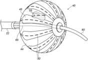
図4は、本発明の一実施形態による、図3の診断バルーン40をボリュームレンダリングする描写図である。図4に示すように、バルーンは、遠位端65を含む内部の可撓性構造によって遠位に保持されるように構成されているため、バルーンをシャフト22に固定するための突出した遠位端を必要とせず、それにより構造全体が滑らかに保たれることから、組織及び血流の乱れが最小限に抑えられる。バルーンは柔らかく丸い遠位端を有し、ガイドワイヤ60上をスライド可能である。バルーン40のスライドを可能とするために、中空の遠位端65は、バルーンが収縮した形態にある場合であっても、又はバルーンが膨張した形態にある場合であっても、ガイドワイヤ60上を移動するように設計されている。4 is a volume-rendered depiction of the
いくつかの実施形態では、電極50が相互接続されて心臓内双極電極構成をなす。別の実施形態では、電極は、皮膚に取り付けられた電極27のうちの1つなどの外部参照電極に関連する信号を感知する。In some embodiments, the
図4に更に図示するように、対向している電極55は、バルーン壁に面していることで区別することができる(バルーン壁及び任意のシーラント又は接着剤は、単に電極55を見せるために透明であるものとして図示されている)。As further shown in FIG. 4, the opposing
図4に示されている図は、単に概念を分かりやすくする目的で選択されたものである。図4は、本発明の実施形態に関連する部分のみを示す。必要に応じて、PCBの電気配線、温度センサ、シーリング要素などの他のシステム要素は省略される。The diagram shown in FIG. 4 has been selected solely for conceptual clarity. FIG. 4 shows only those parts that are relevant to the embodiment of the invention. Where appropriate, other system elements such as PCB electrical wiring, temperature sensors, sealing elements, etc. are omitted.
図5は、本発明の一実施形態による、図3の診断バルーン上に配置された電極対ごとに干渉をキャンセルする方法を概略的に示すフローチャートである。このプロセスは、診断信号感知ステップ70で、電極50などの診断電極が診断信号を感知することから始まる。並行して、干渉感知ステップ72で、診断電極50に対向して配置された参照電極55が干渉信号を感知する。次に、信号受信ステップ74で、プロセッサ41は、診断電極50により感知された診断信号と、参照電極55により感知された干渉信号とを受信する。最後に、信号算出ステップ76で、プロセッサ41は、専用のアルゴリズムを使用して、診断信号から干渉信号を差し引くことにより、補正された診断信号を算出する。5 is a flow chart that illustrates a schematic of a method for canceling interference for each electrode pair disposed on the diagnostic balloon of FIG. 3 according to an embodiment of the present invention. The process begins with a diagnostic electrode, such as
図5に示す例示的なフローチャートは、単に概念を分かりやすくする目的で選択されたものである。更なるステップを含んでもよいが、提示の簡略化ために省略されている。例えば、更なる実施形態では、感知された信号は、プロセッサ41によって受信される前にフィルタリングされる。The exemplary flow chart shown in FIG. 5 has been selected solely for conceptual clarity. Additional steps may be included but have been omitted for simplicity of presentation. For example, in a further embodiment, the sensed signal is filtered before being received by the
上に述べた実施形態は例として挙げたものであり、本発明は上述に具体的に示し説明したものに限定されない点が理解されよう。むしろ、本発明の範囲は、上述の様々な特徴の組み合わせ及びその一部の組み合わせの両方、並びに上述の説明を読むことで当業者により想到されるであろう、また従来技術において開示されていない、それらの変形及び修正を含むものである。参照により本特許出願に援用される文献は、これらの援用文献において、いずれかの用語が本明細書において明示的又は暗示的になされた定義と矛盾して定義されている場合には、本明細書における定義のみを考慮するものとする点を除き、本出願の一部とみなすものとする。It will be understood that the above-described embodiments are given by way of example, and that the present invention is not limited to what has been specifically shown and described above. Rather, the scope of the present invention includes both combinations and subcombinations of the various features described above, as well as variations and modifications thereof that would occur to one skilled in the art upon reading the above description and that are not disclosed in the prior art. Documents incorporated by reference into this patent application are to be considered as part of this application, except that if any term is defined in such incorporated document in a manner that is inconsistent with the definition expressly or impliedly given herein, then only the definition in this specification shall be considered.
〔実施の態様〕
(1) 患者の器官の中に挿入するためのシャフトと、
前記シャフトの遠位端に連結された拡張可能なフレームであって、前記拡張可能なフレームは長手方向軸に沿って延伸しており、前記拡張可能なフレームは、前記長手方向軸の周囲に配置された複数の拡張可能なスパインを含む、拡張可能なフレームと、
前記複数の拡張可能なスパインの外面上に配置されており、かつ、組織と接触している時に診断信号を感知するように構成されている、複数の診断電極と、
前記診断電極に正対して前記拡張可能なスパインの内面上に配置されたそれぞれの複数の参照電極であって、前記複数の参照電極は、前記組織から電気的に絶縁されており、かつ、干渉信号を感知するように構成されている、複数の参照電極と、
プロセッサであって、
前記複数の診断電極によって感知された前記診断信号を受信し、
前記それぞれの複数の参照電極によって感知された前記干渉信号を受信し、
前記診断信号から前記干渉信号を差し引くことによって、補正された診断信号を算出する、
ように構成されている、プロセッサと、
を備える、医療装置。
(2) 所与のスパイン上の前記参照電極は、血液によって伝導される遠距離場信号を検出するように、血流と接触するが組織とは接触しない単一の参照電極として構成されている、実施態様1に記載の医療装置。
(3) 前記拡張可能なスパインのうちの少なくとも1つの拡張可能なスパインは、フレキシブルプリント回路基板(PCB)から作製されており、前記拡張可能なスパイン上の前記診断電極及び前記参照電極は、前記PCBの対向面上に配置されている、実施態様1に記載の医療装置。
(4) 前記シャフトを通して挿入され、前記拡張可能なフレームを前記器官内の標的位置に向かって案内するように構成されている、ガイドワイヤを更に備える、実施態様1に記載の医療装置。
(5) 前記干渉信号は遠距離場の生体電気信号を含む、実施態様1に記載の医療装置。[Embodiment]
(1) a shaft for insertion into a patient's organ;
an expandable frame coupled to a distal end of the shaft, the expandable frame extending along a longitudinal axis, the expandable frame including a plurality of expandable spines disposed about the longitudinal axis;
a plurality of diagnostic electrodes disposed on an exterior surface of the plurality of expandable spines and configured to sense a diagnostic signal when in contact with tissue;
a plurality of reference electrodes, each disposed on an inner surface of the expandable spine opposite the diagnostic electrode, the plurality of reference electrodes being electrically isolated from the tissue and configured to sense an interference signal;
1. A processor comprising:
receiving the diagnostic signals sensed by the plurality of diagnostic electrodes;
receiving the interference signals sensed by each of the plurality of reference electrodes;
calculating a corrected diagnostic signal by subtracting the interference signal from the diagnostic signal;
a processor configured to
A medical device comprising:
(2) The medical device of
3. The medical device of
(4) The medical device of
5. The medical device of
(6) シャフトの遠位端に連結された拡張可能なフレームを含む医療プローブを患者の器官の中に挿入することであって、前記拡張可能なフレームは長手方向軸に沿って延伸しており、前記拡張可能なフレームは、前記長手方向軸の周囲に配置された複数の拡張可能なスパインを含む、ことと、
前記拡張可能なスパインの外面上に配置された複数の診断電極を用いて診断信号を感知することであって、前記複数の診断電極は、組織と接触している時に診断信号を感知するように構成されている、ことと、
前記拡張可能なフレームの表面上に前記複数の診断電極に正対して配置されたそれぞれの複数の参照電極を用いて干渉信号を感知することであって、前記複数の参照電極は前記組織から電気的に絶縁されている、ことと、
プロセッサ内で、前記診断電極によって感知された前記診断信号を受信することと、
前記参照電極によって感知された前記干渉信号を受信することと、
前記診断信号から前記干渉信号を差し引くことによって、補正された診断信号を算出することと、
を含む方法。
(7) 干渉信号を感知することは、血液によって伝導される遠距離場信号を検出するように、血流と接触するが組織とは接触しない単一の参照電極として構成された所与のスパイン上の前記参照電極を用いて干渉信号を感知することを含む、実施態様6に記載の方法。
(8) 前記拡張可能なスパインのうちの少なくとも1つの拡張可能なスパインは、フレキシブルプリント回路基板(PCB)から作製されており、前記拡張可能なスパイン上の前記診断電極及び前記参照電極は、前記PCBの対向面上に配置されている、実施態様6に記載の方法。
(9) 前記シャフトを通してガイドワイヤを挿入することと、前記拡張可能なフレームを前記器官内の標的位置に向かって案内することとを含む、実施態様6に記載の方法。
(10) 干渉信号を感知することは、遠距離場の生体電気信号を感知することを含む、実施態様6に記載の方法。(6) inserting into an organ of a patient a medical probe including an expandable frame coupled to a distal end of a shaft, the expandable frame extending along a longitudinal axis, the expandable frame including a plurality of expandable spines disposed about the longitudinal axis;
sensing diagnostic signals using a plurality of diagnostic electrodes disposed on an exterior surface of the expandable spine, the plurality of diagnostic electrodes configured to sense diagnostic signals when in contact with tissue;
sensing interference signals using a plurality of reference electrodes disposed on a surface of the expandable frame opposite the plurality of diagnostic electrodes, the plurality of reference electrodes being electrically insulated from the tissue;
receiving, in a processor, the diagnostic signal sensed by the diagnostic electrode;
receiving the interference signal sensed by the reference electrode;
calculating a corrected diagnostic signal by subtracting the interference signal from the diagnostic signal;
The method includes:
(7) The method of claim 6, wherein sensing the interference signal includes sensing the interference signal with the reference electrode on a given spine configured as a single reference electrode in contact with the blood flow but not in contact with tissue to detect far-field signals conducted by the blood.
8. The method of claim 6, wherein at least one of the expandable spines is fabricated from a flexible printed circuit board (PCB), and the diagnostic electrode and the reference electrode on the expandable spine are disposed on opposing sides of the PCB.
9. The method of claim 6, further comprising inserting a guidewire through the shaft and guiding the expandable frame towards a target location within the organ.
10. The method of claim 6, wherein sensing an interference signal includes sensing a far-field bioelectric signal.
Claims (4)
Translated fromJapanese前記シャフトの遠位端に連結された拡張可能なフレームであって、前記拡張可能なフレームは長手方向軸に沿って延伸しており、前記拡張可能なフレームは、前記長手方向軸の周囲に配置された複数の拡張可能なスパインを含む、拡張可能なフレームと、
前記複数の拡張可能なスパインの外面上に配置されており、かつ、組織と接触している時に複数の診断信号を感知するように構成されている、複数の診断電極と、
前記複数の診断電極に正対して前記複数の拡張可能なスパインの内面上に配置された複数の参照電極であって、前記複数の参照電極は、前記組織から電気的に絶縁されており、かつ、複数の干渉信号を感知するように構成されている、複数の参照電極と、
プロセッサであって、
前記複数の診断電極によって感知された前記複数の診断信号を受信し、
前記複数の参照電極によって感知された前記複数の干渉信号を受信し、
前記複数の診断信号から前記複数の干渉信号を差し引くことによって、複数の補正された診断信号を算出する、
ように構成されている、プロセッサと、
を備え、
前記複数の拡張可能なスパインの内の1つの拡張可能なスパインの外面上に2つ以上の診断電極が配置され、前記1つの拡張可能なスパインの内面上に単一の参照電極が配置されており、前記単一の参照電極は、血液によって伝導される遠距離場信号を検出するように、血流と接触するが組織とは接触しない、医療装置。 a shaft for insertion into a patient's organ;
an expandable frame coupled to a distal end of the shaft, the expandable frame extending along a longitudinal axis, the expandable frame including a plurality of expandable spines disposed about the longitudinal axis;
a plurality of diagnostic electrodes disposed on an exterior surface of the plurality of expandable spines and configured to sense a plurality of diagnostic signals when in contact with tissue;
a plurality of reference electrodes disposed on an inner surface of the plurality of expandable spines opposite the plurality of diagnostic electrodes, the plurality of reference electrodes being electrically isolated from the tissue and configured to sense a plurality of interfering signals;
1. A processor comprising:
receiving the plurality of diagnostic signals sensed by the plurality of diagnostic electrodes;
receiving the plurality of interference signals sensed by the plurality of reference electrodes;
calculating a plurality of corrected diagnostic signals by subtracting the plurality of interference signals from the plurality of diagnostic signals;
a processor configured to
Equipped with
a medical device comprising: two or more diagnostic electrodes disposed on an outer surface of an expandable spine of the plurality of expandable spines; and a single reference electrode disposed on an inner surface of the one of the expandable spines, the single reference electrode in contact with the blood flow but not in contact with tissue so as to detect far-field signals conducted by the blood.
Applications Claiming Priority (2)
| Application Number | Priority Date | Filing Date | Title |
|---|---|---|---|
| US16/170,631US11452484B2 (en) | 2018-10-25 | 2018-10-25 | Electrodes on double-sided printed circuit board (PCB) to cancel far-held signal |
| US16/170,631 | 2018-10-25 |
Publications (2)
| Publication Number | Publication Date |
|---|---|
| JP2020065932A JP2020065932A (en) | 2020-04-30 |
| JP7467070B2true JP7467070B2 (en) | 2024-04-15 |
Family
ID=68531339
Family Applications (1)
| Application Number | Title | Priority Date | Filing Date |
|---|---|---|---|
| JP2019193268AActiveJP7467070B2 (en) | 2018-10-25 | 2019-10-24 | Electrodes on a double-sided printed circuit board (PCB) for canceling far-field signals |
Country Status (8)
| Country | Link |
|---|---|
| US (1) | US11452484B2 (en) |
| EP (2) | EP4401517A3 (en) |
| JP (1) | JP7467070B2 (en) |
| CN (1) | CN111096787B (en) |
| AU (1) | AU2019222924A1 (en) |
| BR (1) | BR102019020575A2 (en) |
| CA (1) | CA3055656A1 (en) |
| IL (1) | IL269312B2 (en) |
Families Citing this family (28)
| Publication number | Priority date | Publication date | Assignee | Title |
|---|---|---|---|---|
| US10905329B2 (en) | 2016-06-09 | 2021-02-02 | Biosense Webster (Israel) Ltd. | Multi-function conducting elements for a catheter |
| US12029545B2 (en) | 2017-05-30 | 2024-07-09 | Biosense Webster (Israel) Ltd. | Catheter splines as location sensors |
| US20190314083A1 (en) | 2018-04-11 | 2019-10-17 | Biosense Webster (Israel) Ltd. | Flexible Multi-Arm Catheter with Diametrically Opposed Sensing Electrodes |
| US11045628B2 (en) | 2018-12-11 | 2021-06-29 | Biosense Webster (Israel) Ltd. | Balloon catheter with high articulation |
| US11207016B2 (en) | 2018-12-28 | 2021-12-28 | Biosense Webster (Israel) Ltd. | Mapping ECG signals using a multipole electrode assembly |
| US11850051B2 (en) | 2019-04-30 | 2023-12-26 | Biosense Webster (Israel) Ltd. | Mapping grid with high density electrode array |
| US11712172B2 (en) | 2019-07-18 | 2023-08-01 | Biosense Webster (Israel) Ltd. | Visual guidance for positioning a distal end of a medical probe |
| US11950930B2 (en) | 2019-12-12 | 2024-04-09 | Biosense Webster (Israel) Ltd. | Multi-dimensional acquisition of bipolar signals from a catheter |
| US11517218B2 (en) | 2019-12-20 | 2022-12-06 | Biosense Webster (Israel) Ltd. | Selective graphical presentation of electrophysiological parameters |
| US11903639B2 (en) | 2020-04-17 | 2024-02-20 | Biosense Webster (Israel) Ltd. | Flexible distal-end assembly with double-sided electrode array and irrigation |
| US12232874B2 (en) | 2020-05-29 | 2025-02-25 | Biosense Webster (Israel) Ltd. | Electrode apparatus for diagnosis of arrhythmias |
| US11987017B2 (en) | 2020-06-08 | 2024-05-21 | Biosense Webster (Israel) Ltd. | Features to assist in assembly and testing of devices |
| CN112022154A (en)* | 2020-09-10 | 2020-12-04 | 中国科学院半导体研究所 | Flexible neural electrode implantation system for multi-dimensional extraction of neuronal signals |
| US12048479B2 (en) | 2020-09-10 | 2024-07-30 | Biosense Webster (Israel) Ltd. | Surface mounted electrode catheter |
| US11950840B2 (en) | 2020-09-22 | 2024-04-09 | Biosense Webster (Israel) Ltd. | Basket catheter having insulated ablation electrodes |
| US11950841B2 (en) | 2020-09-22 | 2024-04-09 | Biosense Webster (Israel) Ltd. | Basket catheter having insulated ablation electrodes and diagnostic electrodes |
| US12082875B2 (en) | 2020-09-24 | 2024-09-10 | Biosense Webster (Israel) Ltd | Balloon catheter having a coil for sensing tissue temperature and position of the balloon |
| US11974803B2 (en) | 2020-10-12 | 2024-05-07 | Biosense Webster (Israel) Ltd. | Basket catheter with balloon |
| US12201786B2 (en) | 2020-12-17 | 2025-01-21 | Biosense Webster (Israel) Ltd. | Measurement of distal end dimension of catheters using magnetic fields |
| US11918383B2 (en) | 2020-12-21 | 2024-03-05 | Biosense Webster (Israel) Ltd. | Visualizing performance of catheter electrodes |
| US12064170B2 (en) | 2021-05-13 | 2024-08-20 | Biosense Webster (Israel) Ltd. | Distal assembly for catheter with lumens running along spines |
| US12364426B2 (en) | 2021-08-12 | 2025-07-22 | Biosense Webster (Israel) Ltd. | Electro-anatomical mapping and annotation presented in electrophysiological procedures |
| US12004804B2 (en) | 2021-09-09 | 2024-06-11 | Biosense Webster (Israel) Ltd. | Basket catheter with mushroom shape distal tip |
| US12011280B2 (en) | 2021-10-04 | 2024-06-18 | Biosense Webster (Israel) Ltd. | Electrophysiological mapping in the presence of injury current |
| US12419683B2 (en) | 2021-12-22 | 2025-09-23 | Biosense Webster (Israel) Ltd. | Irreversible electroporation with shorted electrodes |
| US20240216054A1 (en)* | 2022-12-29 | 2024-07-04 | Biosense Webster (Israel) Ltd. | Systems and methods for cylindrical cage mapping and ablation catheters comprising flexible circuits |
| CN115998413A (en)* | 2023-03-27 | 2023-04-25 | 成都美创医疗科技股份有限公司 | Rhinitis treatment apparatus and production method thereof |
| CN118615011B (en)* | 2024-07-08 | 2025-02-11 | 南京康友医疗科技有限公司 | Pulse ablation catheter |
Citations (5)
| Publication number | Priority date | Publication date | Assignee | Title |
|---|---|---|---|---|
| US5313943A (en) | 1992-09-25 | 1994-05-24 | Ep Technologies, Inc. | Catheters and methods for performing cardiac diagnosis and treatment |
| JP2003210427A (en) | 2001-12-14 | 2003-07-29 | Biosense Webster Inc | Catheter |
| US20160317093A1 (en) | 2015-04-30 | 2016-11-03 | The Regents Of The University Of Michigan | Method and system for mapping and analyzing cardiac electrical activity |
| JP2017516588A (en) | 2014-06-04 | 2017-06-22 | ボストン サイエンティフィック サイムド,インコーポレイテッドBoston Scientific Scimed,Inc. | Electrode assembly |
| JP2018518244A (en) | 2015-05-12 | 2018-07-12 | アクタス メディカル インクAcutus Medical,Inc. | Ultrasonic sequencing system and method |
Family Cites Families (33)
| Publication number | Priority date | Publication date | Assignee | Title |
|---|---|---|---|---|
| US5228442A (en)* | 1991-02-15 | 1993-07-20 | Cardiac Pathways Corporation | Method for mapping, ablation, and stimulation using an endocardial catheter |
| US5662108A (en) | 1992-09-23 | 1997-09-02 | Endocardial Solutions, Inc. | Electrophysiology mapping system |
| US5476495A (en) | 1993-03-16 | 1995-12-19 | Ep Technologies, Inc. | Cardiac mapping and ablation systems |
| US5697377A (en) | 1995-11-22 | 1997-12-16 | Medtronic, Inc. | Catheter mapping system and method |
| US5792070A (en) | 1996-08-30 | 1998-08-11 | Urologix, Inc. | Rectal thermosensing unit |
| US6050267A (en) | 1997-04-28 | 2000-04-18 | American Cardiac Ablation Co. Inc. | Catheter positioning system |
| US6408199B1 (en) | 2000-07-07 | 2002-06-18 | Biosense, Inc. | Bipolar mapping of intracardiac potentials with electrode having blood permeable covering |
| US6405067B1 (en) | 2000-07-07 | 2002-06-11 | Biosense Webster, Inc. | Catheter with tip electrode having a recessed ring electrode mounted thereon |
| JP2002078809A (en) | 2000-09-07 | 2002-03-19 | Shutaro Satake | Balloon catheter for electrically isolating pulmonary vein |
| US7996083B2 (en) | 2004-06-02 | 2011-08-09 | Cardiac Pacemakers, Inc. | Far-field sensing channel for implantable cardiac device |
| US7869865B2 (en) | 2005-01-07 | 2011-01-11 | Biosense Webster, Inc. | Current-based position sensing |
| US7848787B2 (en) | 2005-07-08 | 2010-12-07 | Biosense Webster, Inc. | Relative impedance measurement |
| US7756576B2 (en) | 2005-08-26 | 2010-07-13 | Biosense Webster, Inc. | Position sensing and detection of skin impedance |
| EP1937357B1 (en) | 2005-09-06 | 2023-11-01 | Impulse Dynamics N.V. | Apparatus for delivering electrical signals to a heart |
| DE602007002677D1 (en) | 2006-09-07 | 2009-11-19 | Biotronik Crm Patent Ag | Composite far-field electrocardiogram |
| US9126035B2 (en) | 2011-10-26 | 2015-09-08 | Radiadyne Llc | Shaped conforming medical balloons |
| US8456182B2 (en) | 2008-09-30 | 2013-06-04 | Biosense Webster, Inc. | Current localization tracker |
| US9545216B2 (en) | 2011-08-05 | 2017-01-17 | Mc10, Inc. | Catheter balloon methods and apparatus employing sensing elements |
| US9795442B2 (en)* | 2008-11-11 | 2017-10-24 | Shifamed Holdings, Llc | Ablation catheters |
| US8103338B2 (en) | 2009-05-08 | 2012-01-24 | Rhythmia Medical, Inc. | Impedance based anatomy generation |
| SE0900936A1 (en) | 2009-07-06 | 2010-12-28 | Cathprint Ab | Catheter and method for manufacturing such catheter |
| US9655677B2 (en) | 2010-05-12 | 2017-05-23 | Shifamed Holdings, Llc | Ablation catheters including a balloon and electrodes |
| US20140025069A1 (en)* | 2012-07-17 | 2014-01-23 | Boston Scientific Scimed, Inc. | Renal nerve modulation catheter design |
| US9301795B2 (en) | 2012-10-29 | 2016-04-05 | Ablative Solutions, Inc. | Transvascular catheter for extravascular delivery |
| US9615878B2 (en)* | 2012-12-21 | 2017-04-11 | Volcano Corporation | Device, system, and method for imaging and tissue characterization of ablated tissue |
| CN105358070B (en) | 2013-02-08 | 2018-03-23 | 阿库图森医疗有限公司 | Expandable catheter assembly with flexible printed circuit board |
| US9993279B2 (en)* | 2013-12-06 | 2018-06-12 | Medtronic Cryocath Lp | Distal balloon impedance and temperature recording to monitor pulmonary vein ablation and occlusion |
| US9554718B2 (en)* | 2014-01-29 | 2017-01-31 | Biosense Webster (Israel) Ltd. | Double bipolar configuration for atrial fibrillation annotation |
| WO2015187371A1 (en) | 2014-06-03 | 2015-12-10 | Boston Scientific Scimed, Inc. | Medical devices for mapping cardiac tissue |
| CN106687168A (en)* | 2014-09-12 | 2017-05-17 | X-节奏有限责任公司 | Multi-electrode mapping catheter |
| US9833161B2 (en)* | 2015-02-09 | 2017-12-05 | Biosense Webster (Israel) Ltd. | Basket catheter with far-field electrode |
| US10143399B2 (en) | 2015-04-02 | 2018-12-04 | Medtronic Ablation Frontiers Llc | Tissue contact sensing with a multi electrode ablation catheter |
| EP3115011A1 (en) | 2015-07-10 | 2017-01-11 | AFreeze GmbH | Ablation catheter device with electrodes for detecting an electric response of biological material |
- 2018
- 2018-10-25USUS16/170,631patent/US11452484B2/enactiveActive
- 2019
- 2019-08-30AUAU2019222924Apatent/AU2019222924A1/ennot_activeAbandoned
- 2019-09-12ILIL269312Apatent/IL269312B2/enunknown
- 2019-09-17CACA3055656Apatent/CA3055656A1/ennot_activeAbandoned
- 2019-09-30BRBR102019020575Apatent/BR102019020575A2/ennot_activeIP Right Cessation
- 2019-10-24EPEP24179030.2Apatent/EP4401517A3/enactivePending
- 2019-10-24JPJP2019193268Apatent/JP7467070B2/enactiveActive
- 2019-10-24EPEP19205099.5Apatent/EP3643231B1/enactiveActive
- 2019-10-25CNCN201911022755.0Apatent/CN111096787B/enactiveActive
Patent Citations (5)
| Publication number | Priority date | Publication date | Assignee | Title |
|---|---|---|---|---|
| US5313943A (en) | 1992-09-25 | 1994-05-24 | Ep Technologies, Inc. | Catheters and methods for performing cardiac diagnosis and treatment |
| JP2003210427A (en) | 2001-12-14 | 2003-07-29 | Biosense Webster Inc | Catheter |
| JP2017516588A (en) | 2014-06-04 | 2017-06-22 | ボストン サイエンティフィック サイムド,インコーポレイテッドBoston Scientific Scimed,Inc. | Electrode assembly |
| US20160317093A1 (en) | 2015-04-30 | 2016-11-03 | The Regents Of The University Of Michigan | Method and system for mapping and analyzing cardiac electrical activity |
| JP2018518244A (en) | 2015-05-12 | 2018-07-12 | アクタス メディカル インクAcutus Medical,Inc. | Ultrasonic sequencing system and method |
Also Published As
| Publication number | Publication date |
|---|---|
| CA3055656A1 (en) | 2020-04-25 |
| US11452484B2 (en) | 2022-09-27 |
| AU2019222924A1 (en) | 2020-05-14 |
| EP3643231B1 (en) | 2024-07-03 |
| BR102019020575A2 (en) | 2020-05-05 |
| EP4401517A3 (en) | 2024-10-02 |
| EP4401517A2 (en) | 2024-07-17 |
| US20200129128A1 (en) | 2020-04-30 |
| CN111096787A (en) | 2020-05-05 |
| EP3643231A2 (en) | 2020-04-29 |
| IL269312B1 (en) | 2023-03-01 |
| IL269312A (en) | 2020-04-30 |
| IL269312B2 (en) | 2023-07-01 |
| JP2020065932A (en) | 2020-04-30 |
| CN111096787B (en) | 2024-05-24 |
| EP3643231A3 (en) | 2020-07-01 |
| EP3643231C0 (en) | 2024-07-03 |
Similar Documents
| Publication | Publication Date | Title |
|---|---|---|
| JP7467070B2 (en) | Electrodes on a double-sided printed circuit board (PCB) for canceling far-field signals | |
| JP7460350B2 (en) | Balloon catheter with diagnostic electrodes, far-field sensing electrodes and guidewire | |
| US12232804B2 (en) | Configuring perimeter of balloon electrode as location sensor | |
| CN112040861B (en) | High-density electrode mapping catheter | |
| US20190021620A1 (en) | Masked ring electrodes | |
| JP2016144642A (en) | Basket catheter with far-field electrode | |
| JP2021090756A (en) | Balloon catheter with position sensors | |
| US20240173071A1 (en) | Flexible Distal-End Assembly with Double-Sided Electrode Array and Irrigation | |
| EP4137051B1 (en) | Electro-anatomical mapping and annotation presented in electrophysiological procedures | |
| CN114073576A (en) | Balloon catheter with ablation electrode and return electrode |
Legal Events
| Date | Code | Title | Description |
|---|---|---|---|
| A621 | Written request for application examination | Free format text:JAPANESE INTERMEDIATE CODE: A621 Effective date:20220812 | |
| A131 | Notification of reasons for refusal | Free format text:JAPANESE INTERMEDIATE CODE: A131 Effective date:20230523 | |
| A977 | Report on retrieval | Free format text:JAPANESE INTERMEDIATE CODE: A971007 Effective date:20230526 | |
| A521 | Request for written amendment filed | Free format text:JAPANESE INTERMEDIATE CODE: A523 Effective date:20230817 | |
| A02 | Decision of refusal | Free format text:JAPANESE INTERMEDIATE CODE: A02 Effective date:20231107 | |
| A521 | Request for written amendment filed | Free format text:JAPANESE INTERMEDIATE CODE: A523 Effective date:20240213 | |
| A911 | Transfer to examiner for re-examination before appeal (zenchi) | Free format text:JAPANESE INTERMEDIATE CODE: A911 Effective date:20240220 | |
| TRDD | Decision of grant or rejection written | ||
| A01 | Written decision to grant a patent or to grant a registration (utility model) | Free format text:JAPANESE INTERMEDIATE CODE: A01 Effective date:20240305 | |
| A61 | First payment of annual fees (during grant procedure) | Free format text:JAPANESE INTERMEDIATE CODE: A61 Effective date:20240403 | |
| R150 | Certificate of patent or registration of utility model | Ref document number:7467070 Country of ref document:JP Free format text:JAPANESE INTERMEDIATE CODE: R150 |