JP7466999B2 - Pure Water Generator - Google Patents
Pure Water GeneratorDownload PDFInfo
- Publication number
- JP7466999B2 JP7466999B2JP2020116383AJP2020116383AJP7466999B2JP 7466999 B2JP7466999 B2JP 7466999B2JP 2020116383 AJP2020116383 AJP 2020116383AJP 2020116383 AJP2020116383 AJP 2020116383AJP 7466999 B2JP7466999 B2JP 7466999B2
- Authority
- JP
- Japan
- Prior art keywords
- water
- valve
- ion exchange
- storage tank
- unit
- Prior art date
- Legal status (The legal status is an assumption and is not a legal conclusion. Google has not performed a legal analysis and makes no representation as to the accuracy of the status listed.)
- Active
Links
Images


Landscapes
- Treatment Of Water By Ion Exchange (AREA)
- Physical Water Treatments (AREA)
Description
Translated fromJapanese本発明は、水に含まれる不純物等を除去し、不純物が極めて少ない純水を生成する純水生成装置に関する。The present invention relates to a pure water generating device that removes impurities from water and produces pure water with extremely low impurity content.
電子機器に搭載されるデバイスチップの製造工程では、まず、半導体材料で形成されたウエーハの表面に互いに交差する複数の分割予定ライン(ストリート)を設定する。そして、該分割予定ラインで区画された各領域にそれぞれIC(Integrated Circuit)、LSI(Large Scale Integration)等のデバイスを形成する。その後、分割予定ラインに沿ってウエーハを分割すると、複数のデバイスチップが得られる。ウエーハの分割には、環状の切削ブレードでウエーハを切削する切削装置等が用いられる。In the manufacturing process of device chips to be mounted on electronic devices, first, multiple planned division lines (streets) that intersect with each other are set on the surface of a wafer formed from semiconductor material. Then, devices such as ICs (Integrated Circuits) and LSIs (Large Scale Integration) are formed in each area partitioned by the planned division lines. The wafer is then divided along the planned division lines to obtain multiple device chips. A cutting device that cuts the wafer with an annular cutting blade is used to divide the wafer.
また、近年では、電子機器の小型化、薄型化に伴い、デバイスチップにも薄型化が求められている。そこで、ウエーハの分割前にウエーハを裏面側から研削することでウエーハを薄化する処理が施される。ウエーハの研削には、複数の研削砥石を備える研削ホイールでウエーハを研削する研削装置等が用いられる。In recent years, as electronic devices have become smaller and thinner, there is also a demand for thinner device chips. Therefore, before dividing the wafer, the wafer is ground from the back side to thin it. For grinding the wafer, a grinding device that grinds the wafer with a grinding wheel equipped with multiple grinding stones is used.
切削装置、研削装置等の加工装置を用いてウエーハを加工する際には、ウエーハに純水等の加工液が供給される。この加工液によって、ウエーハと加工工具(切削ブレード、研削ホイール等)とが冷却されるとともに、発生した加工屑が洗い流される。加工装置で使用された純水は、廃液として加工装置の外部に排出される。ここで、加工装置等から排出された水を浄化し、純水を生成する純水生成装置が知られている(特許文献1参照)。When processing a wafer using a processing device such as a cutting device or a grinding device, a processing liquid such as pure water is supplied to the wafer. This processing liquid cools the wafer and processing tools (cutting blades, grinding wheels, etc.) and washes away processing debris. The pure water used in the processing device is discharged outside the processing device as waste liquid. A pure water generating device is known that purifies water discharged from processing devices and generates pure water (see Patent Document 1).
純水生成装置は、水を貯める貯水タンクと、貯水タンクから送り出された水を濾過する第1の濾過部と、濾過部で濾過された水に紫外線を照射して該水に含まれる有機物を破壊する紫外線照射ユニットと、を備える。さらに、紫外線照射ユニットで紫外線が照射された該水に含まれる不純物イオンを交換するイオン交換ユニットと、イオン交換ユニットで不純物イオンが除去された水をさらに濾過する第2の濾過部と、を有する。純水生成装置を構成する各構成要素は、それぞれ、所定の方法で水を浄化する。The pure water generating apparatus includes a water storage tank for storing water, a first filtration section for filtering the water sent out from the water storage tank, and an ultraviolet irradiation unit for irradiating the water filtered by the filtration section with ultraviolet light to destroy organic matter contained in the water. It further includes an ion exchange unit for exchanging impurity ions contained in the water irradiated with ultraviolet light by the ultraviolet irradiation unit, and a second filtration section for further filtering the water from which the impurity ions have been removed by the ion exchange unit. Each of the components constituting the pure water generating apparatus purifies water using a predetermined method.
純水生成装置の各構成要素では、水を十分に浄化できず、許容される水準を超える不純物を含む水が下流の他の構成要素に流れる場合がある。この場合、十分に浄化されていない水を受けた該他の構成要素に過度の負荷がかかり、該構成要素が急速に劣化する。また、純水生成装置の最後部である第2の濾過部で水を十分に浄化できなかった場合、清浄度が所定の水準に満たない水が純水生成装置から流出することとなり、純水の使用箇所で問題が生じる。このように純水生成装置には解決すべき課題がある。In some cases, each component of the pure water generating apparatus is unable to sufficiently purify the water, causing water containing impurities above the allowable level to flow to other downstream components. In this case, excessive load is placed on the other components that receive the insufficiently purified water, causing rapid deterioration of the components. Furthermore, if the water cannot be sufficiently purified in the second filtration section, which is the last part of the pure water generating apparatus, water that does not meet the specified level of cleanliness will flow out of the pure water generating apparatus, causing problems where the pure water is used. In this way, pure water generating apparatuses have problems that need to be solved.
本発明はかかる問題に鑑みてなされたものであり、その目的とするところは、水に所定の処理を実施する各構成要素で水を十分に浄化でき、不純物の極めて少ない純水を生成できる純水生成装置を提供することである。The present invention was made in consideration of these problems, and its purpose is to provide a pure water generating device that can sufficiently purify water using each component that performs a specific treatment on the water, and can generate pure water with extremely few impurities.
本発明の一態様によれば、純水を生成する純水生成装置であって、水を貯水する貯水タンクと、該貯水タンクに連通し、該貯水タンクから水を送り出すポンプと、該ポンプにより該貯水タンクから送り出された水を濾過する第1の濾過部と、該第1の濾過部で濾過された水に紫外線を照射して該水に含まれる有機物を破壊する紫外線照射ユニットと、該紫外線照射ユニットにより紫外線が照射された水に含まれる不純物イオンを交換するイオン交換ユニットと、該イオン交換ユニットで不純物イオンが除去された水を濾過する第2の濾過部と、該第1の濾過部と、該紫外線照射ユニットと、該イオン交換ユニットと、該第2の濾過部と、のいずれか一つである下流への水の流入を規制できるバルブと、該貯水タンクに接続されており、該バルブにより規制された該水が該貯水タンクに戻るための経路となる戻し経路と、を備え、該バルブにより規制された水は、該下流に流れないことを特徴とする純水生成装置が提供される。 According to one aspect of the present invention, there is provided a pure water generating apparatus for generating pure water, comprising: a water storage tank for storing water; a pump connected to the water storage tank and for pumping water out of the water storage tank; a first filtration section for filtering the water pumped out of the water storage tank by the pump; an ultraviolet irradiation unit for irradiating the water filtered by the first filtration section with ultraviolet light to destroy organic matter contained in the water; an ion exchange unit for exchanging impurity ions contained in the water irradiated with ultraviolet light by the ultraviolet irradiation unit; a second filtration section for filtering the water from which the impurity ions have been removed by the ion exchange unit; a valve for restricting the inflow of waterdownstream of any one of the first filtration section, the ultraviolet irradiation unit, the ion exchange unit, and the second filtration section; and a return path connected to the water storage tank and serving as a path forthe water regulated by the valve to return to the water storage tank, wherein the water regulated by the valve does not flow downstream .
また、本発明の他の一態様によれば、純水を生成する純水生成装置であって、水を貯水する貯水タンクと、該貯水タンクに連通し水を送り出すポンプと、該ポンプにより該貯水タンクから送り出された水を濾過する第1の濾過部と、該第1の濾過部に連通し、該第1の濾過部で濾過された水に紫外線を照射して該水に含まれる有機物を破壊する紫外線照射ユニットと、該紫外線照射ユニットに連通し、該紫外線照射ユニットにより紫外線が照射された水に含まれる不純物イオンを交換するイオン交換ユニットと、該イオン交換ユニットに連通し、該イオン交換ユニットで不純物イオンが除去された水を濾過する第2の濾過部と、該第1の濾過部から該紫外線照射ユニットへの水の流出を規制できる第1のバルブと、該紫外線照射ユニットから該イオン交換ユニットへの水の流出を規制できる第2のバルブと、該イオン交換ユニットから該第2の濾過部への水の流出を規制できる第3のバルブと、該第2の濾過部からの流出する水を規制できる第4のバルブと、該第1のバルブで該第1の濾過部から該紫外線照射ユニットへの流出が規制された水を該貯水タンクに戻す第1の戻し経路と、該第2のバルブで該紫外線照射ユニットから該イオン交換ユニットへの流出が規制された水を該貯水タンクに戻す第2の戻し経路と、該第3のバルブで該イオン交換ユニットから該第2の濾過部への流出が規制された水を該貯水タンクに戻す第3の戻し経路と、該第4のバルブで該第2の濾過部からの流出が規制された水を該貯水タンクに戻す第4の戻し経路と、該第1のバルブと、該第2のバルブと、該第3のバルブと、該第4のバルブと、制御する制御ユニットと、を備え、該制御ユニットは、該第1のバルブで該第1の濾過部から該紫外線照射ユニットへの水の流出を規制して該紫外線照射ユニットに水を流さず、該ポンプと、該第1の濾過部と、該貯水タンクと、を該第1の戻し経路を介して接続して水を循環させる第1の循環モードと、該第1のバルブで水の流出を規制せず、該第2のバルブで該紫外線照射ユニットから該イオン交換ユニットへの水の流出を規制して該イオン交換ユニットに水を流さず、該ポンプと、該第1の濾過部と、該紫外線照射ユニットと、該貯水タンクと、を該第2の戻し経路を介して接続して水を循環させる第2の循環モードと、該第1のバルブ及び該第2のバルブで水の流出を規制せず、該第3のバルブで該イオン交換ユニットから該第2の濾過部への水の流出を規制して該第2の濾過部に水を流さず、該ポンプと、該第1の濾過部と、該紫外線照射ユニットと、該イオン交換ユニットと、該貯水タンクと、を該第3の戻し経路を介して接続して水を循環させる第3の循環モードと、該第1のバルブ、該第2のバルブ、及び該第3のバルブで水の流出を規制せず、該第4のバルブで該第2の濾過部からの水の流出を規制して該第2の濾過部から下流に水を流さず、該ポンプと、該第1の濾過部と、該紫外線照射ユニットと、該イオン交換ユニットと、該第2の濾過部と、該貯水タンクと、を該第4の戻し経路を介して接続して水を循環させる第4の循環モードと、に切り替え可能であることを特徴とする純水生成装置が提供される。 According to another aspect of the present invention, there is provided a pure water generating apparatus for generating pure water, the pure water generating apparatus including a water storage tank for storing water, a pump communicating with the water storage tank and pumping out water, a first filtration section for filtering the water pumped out from the water storage tank by the pump, an ultraviolet irradiation unit communicating with the first filtration section for irradiating the water filtered by the first filtration section with ultraviolet light to destroy organic matter contained in the water, an ion exchange unit communicating with the ultraviolet irradiation unit for exchanging impurity ions contained in the water irradiated with ultraviolet light by the ultraviolet irradiation unit, a second filtration section communicating with the ion exchange unit for filtering the water from which the impurity ions have been removed by the ion exchange unit, a first valve for restricting the outflow of water from the first filtration section to the ultraviolet irradiation unit, and a second valve for filtering water from the ultraviolet irradiation unit. a second valve capable of restricting the outflow of water from the ion exchange unit to the ion exchange unit, a third valve capable of restricting the outflow of water from the ion exchange unit to the second filtration unit, a fourth valve capable of restricting the outflow of water from the second filtration unit, a first return path for returning to the water storage tank the water whose outflow from the first filtration unit to the ultraviolet irradiation unit is restricted by the first valve, a second return path for returning to the water storage tank the water whose outflow from the ultraviolet irradiation unit to the ion exchange unit is restricted by the second valve, a third return path for returning to the water storage tank the water whose outflow from the ion exchange unit to the second filtration unit is restricted by the third valve, and a fourth return path for returning to the water storage tank the water whose outflow from the second filtration unit is restricted by the fourth valve, a control unit for controlling the pump, the third valve, and the fourth valve, and the control unit controls: a first circulation mode in which the first valve regulates the outflow of water from the first filtration section to the ultravioletirradiation unit to prevent water from flowing into the ultraviolet irradiation unit, and the pump, the first filtration section, and the water storage tank are connected via the first return path to circulate water; a second circulation mode in which the first valve does not regulate the outflow of water, the second valve regulates the outflow of water from the ultraviolet irradiation unit tothe ion exchange unit to prevent water from flowing into the ion exchange unit , and the pump, the first filtration section, the ultraviolet irradiation unit, and the water storage tank are connected via the second return path to circulate water; and and a fourth circulation mode in which the first valve, the second valve, and the third valve do not restrict the outflow of water from the second filtration section, so that waterdoes not flow into the second filtration section, and the pump, the first filtration section, the ultraviolet irradiation unit, the ion exchange unit, and the water storage tank are connected via the third return pathto circulate water .
好ましくは、該イオン交換ユニットは、第1のイオン交換樹脂部と、該第1のイオン交換樹脂部に連通された第2のイオン交換樹脂部と、を有し、該第1のイオン交換樹脂部から該第2のイオン交換樹脂部への水の流出を規制できる第5のバルブと、該第5のバルブで該第1のイオン交換樹脂部から該第2のイオン交換樹脂部への流出が規制された水を該貯水タンクに戻す第5の戻し経路と、をさらに有し、該制御ユニットは、さらに、該第5のバルブで該第1のイオン交換樹脂部から該第2のイオン交換樹脂部への水の流出を規制して該第2のイオン交換樹脂部に水を流さず、該ポンプと、該第1の濾過部と、該紫外線照射ユニットと、該イオン交換ユニットの該第1のイオン交換樹脂部と、を該第5の戻し経路を介して接続して水を循環させる第5の循環モードに切り替えられる。 Preferably, the ion exchange unit has a first ion exchange resin part and a second ion exchange resin part connected to the first ion exchange resin part, a fifth valve capable of regulating the outflow of water from the first ion exchange resin part to the second ion exchange resin part, and a fifth return path for returning the water whose outflow from the first ion exchange resin part to the second ion exchange resin part is regulated by the fifth valve to the water storage tank, and the control unit is further switched to a fifth circulation mode in which the fifth valve regulates the outflow of water from the first ion exchange resin part to the second ionexchange resin part to prevent water from flowing into the second ion exchange resin part , and the pump, the first filtration part, the ultraviolet irradiation unit, and the first ion exchange resin part of the ion exchange unit are connected via the fifth return path to circulate water.
本発明のさらに他の一態様によれば、純水を生成する純水生成装置であって、水を貯水する貯水タンクと、該貯水タンクに連通し水を送り出すポンプと、該ポンプから送り出された水の流路となる主流路と、第1のバルブを介して該主流路に接続され、該主流路から供給された水を濾過し、第1の戻し経路を介して該水を該貯水タンクに戻す第1の濾過部と、第2のバルブを介して該主流路に接続され、該主流路から供給された水に紫外線を照射して該水に含まれる有機物を破壊し、第2の戻し経路を介して該水を該貯水タンクに戻す紫外線照射ユニットと、第3のバルブを介して該主流路に接続され、該主流路から供給された水に含まれる不純物イオンを交換し、第3の戻し経路を介して該水を該貯水タンクに戻すイオン交換ユニットと、第4のバルブを介して該主流路に接続され、該主流路から供給された水を濾過し、第4の戻し経路を介して該水を該貯水タンクに戻す第2の濾過部と、該第1のバルブと、該第2のバルブと、該第3のバルブと、該第4のバルブと、を制御できる制御ユニットと、を備え、該制御ユニットは、該第1のバルブを開にし、該第2のバルブ、該第3のバルブ、及び該第4のバルブを閉にして、該紫外線照射ユニットと、該イオン交換ユニットと、該第2の濾過部と、に水を流さず、該第1の濾過部及び該貯水タンクに該第1の戻し経路及び該主流路を介して水を循環させる第1の循環モードと、該第2のバルブを開にし、該第1のバルブ、該第3のバルブ、及び該第4のバルブを閉にして、該第1の濾過部と、該イオン交換ユニットと、該第2の濾過部と、に水を流さず、該紫外線照射ユニット及び該貯水タンクに該第2の戻し経路及び該主流路を介して水を循環させる第2の循環モードと、該第3のバルブを開にし、該第1のバルブ、該第2のバルブ、及び該第4のバルブを閉にして、該第1の濾過部と、該紫外線照射ユニットと、該第2の濾過部と、に水を流さず、該イオン交換ユニット及び該貯水タンクに該第3の戻し経路及び該主流路を介して水を循環させる第3の循環モードと、該第4のバルブを開にし、該第1のバルブ、該第2のバルブ、及び該第3のバルブを閉にして、該第1の濾過部と、該紫外線照射ユニットと、該イオン交換ユニットと、に水を流さず、該第2の濾過部及び該貯水タンクに該第4の戻し経路及び該主流路を介して水を循環させる第4の循環モードと、を切り替え可能であることを特徴とする純水生成装置が提供される。 According to yet another aspect of the present invention, there is provided a pure water generating apparatus for generating pure water, the pure water generating apparatus including a water storage tank for storing water, a pump communicating with the water storage tank and pumping out water, a main flow path for the water pumped out from the pump, a first filtration section connected to the main flow path via a first valve and filtering the water supplied from the main flow path and returning the water to the water storage tank via a first return path, an ultraviolet irradiation unit connected to the main flow path via a second valve and irradiating the water supplied from the main flow path with ultraviolet light to destroy organic matter contained in the water and returning the water to the water storage tank via a second return path, and a third valve. the ion exchange unit connected to the main flow path via a fourth valve, exchanging impurity ions contained in the water supplied from the main flow path and returning the water to the water storage tank via a third return path; a second filtration section connected to the main flow path via a fourth valve, filtering the water supplied from the main flow path and returning the water to the water storage tank via a fourth return path; and a control unit capable of controlling the first valve, the second valve, the third valve and the fourth valve, wherein the control unit opens the first valve and closes the second valve, the third valve and the fourth valve tocontrol the ultraviolet ray irradiation unit. a first circulation modein which water is not flowed through the ultraviolet irradiation unit, the ion exchange unit, and the second filtration unit, and water is circulated to the first filtration unit and the water storage tank via the first return path and the main flow path; a second circulation modein which water is not flowed through the first filtration unit, the ion exchange unit, and the second filtration unit, and water is circulated to the ultraviolet irradiation unit and the water storage tank via the second return path and the main flow path by opening the second valve, and closing the first valve, the third valve, and the fourth valve; and a third circulationmode in which water is not flowed through the first filtration section, the ultraviolet irradiation unit, and the second filtration section, and water is circulated to the ion exchange unit and the water storage tank via the third return path and the main flow path, and a fourth circulation mode in which the fourth valve is opened, the first valve, the second valve, and the third valve are closed,and water is not flowed through the first filtration section, the ultraviolet irradiation unit, and the ion exchange unit, and water is circulated to the second filtration section and the water storage tank via the fourth return path and the main flow path.
好ましくは、該貯水タンクは、蓋状のコネクターが着脱可能に固定される開口部を有し、該コネクターは、該ポンプに接続し、該貯水タンクに貯水された水を送り出す経路となる主ポートを備える。Preferably, the water tank has an opening to which a lid-shaped connector is removably fixed, and the connector is provided with a main port that connects to the pump and serves as a path for discharging the water stored in the water tank.
また、好ましくは、該コネクターは、該第1の戻し経路に接続する第1の戻しポートと、該第2の戻し経路に接続する第2の戻しポートと、該第3の戻し経路に接続する第3の戻しポートと、該第4の戻し経路に接続する第4の戻しポートと、をさらに備える。Also, preferably, the connector further includes a first return port connected to the first return path, a second return port connected to the second return path, a third return port connected to the third return path, and a fourth return port connected to the fourth return path.
さらに、好ましくは、該コネクターは、該貯水タンクの該開口部に該コネクターが固定されたときに該貯水タンクの内部に突き出る突出部と、一端が該主ポートに接続され、他端が該突出部の外面に形成された吸水口に接続された吸水路と、該吸水口よりも該主ポートに近い位置で該突出部の該外面に形成された吸気口と、該貯水タンクの該開口部に該コネクターが固定されたときに該貯水タンクの外部に露出する排気口と、一端が該吸気口に接続され、他端が該排気口に接続された排気路と、をさらに備える。Moreover, preferably, the connector further comprises a protrusion that protrudes into the water tank when the connector is fixed to the opening of the water tank, a water intake passage having one end connected to the main port and the other end connected to a water intake port formed on the outer surface of the protrusion, an air intake port formed on the outer surface of the protrusion at a position closer to the main port than the water intake port, an exhaust port that is exposed to the outside of the water tank when the connector is fixed to the opening of the water tank, and an exhaust passage having one end connected to the air intake port and the other end connected to the exhaust port.
また、好ましくは、該貯水タンクに戻される水、または、該ポンプにより該貯水タンクから送り出された水に含まれるパーティクルを計数するパーティクルカウンターと、該貯水タンクに戻される水、または、該ポンプにより該貯水タンクから送り出された水の比抵抗値を測定する比抵抗値センサーと、の一方または両方をさらに備える。Preferably, the device further comprises one or both of a particle counter that counts particles contained in the water returned to the water storage tank or the water pumped out of the water storage tank by the pump, and a resistivity sensor that measures the resistivity of the water returned to the water storage tank or the water pumped out of the water storage tank by the pump.
さらに、好ましくは、該貯水タンクは、外気との接触を避ける密閉容器である。Moreover, preferably, the water tank is a sealed container that avoids contact with outside air.
また、好ましくは、該貯水タンクは、内部に貯水された水の量に応じて変形することにより容量を増減できる。また、好ましくは、該バルブは、該下流と、該戻し経路と、の一方に選択的に水を流す三方弁である。または、好ましくは、該第1のバルブは、該紫外線照射ユニットと、該第1の戻し経路と、の一方に選択的に水を流す三方弁であり、該第2のバルブは、該イオン交換ユニットと、該第2の戻し経路と、の一方に選択的に水を流す三方弁であり、該第3のバルブは、該第2の濾過部と、該第3の戻し経路と、の一方に選択的に水を流す三方弁であり、該第4のバルブは、該下流と、該第4の戻し経路と、の一方に選択的に水を流す三方弁である。または好ましくは、該第1のバルブは、該紫外線照射ユニットと、該第1の戻し経路と、の一方に選択的に水を流す三方弁であり、該第2のバルブは、該イオン交換ユニットと、該第2の戻し経路と、の一方に選択的に水を流す三方弁であり、該第3のバルブは、該第2の濾過部と、該第3の戻し経路と、の一方に選択的に水を流す三方弁であり、該第4のバルブは、該下流と、該第4の戻し経路と、の一方に選択的に水を流す三方弁であり、該第5のバルブは、該第2のイオン交換樹脂部と、該第5の戻し経路と、の一方に選択的に水を流す三方弁である。 Also, preferably, the water storage tank can increase or decrease its capacity by deforming according to the amount of water stored therein.Also, preferably, the valve is a three-way valve that selectively allows water to flow to one of the downstream and the return path. Alternatively, preferably, the first valve is a three-way valve that selectively allows water to flow to one of the ultraviolet irradiation unit and the first return path, the second valve is a three-way valve that selectively allows water to flow to one of the ion exchange unit and the second return path, the third valve is a three-way valve that selectively allows water to flow to one of the second filtration unit and the third return path, and the fourth valve is a three-way valve that selectively allows water to flow to one of the downstream and the fourth return path. Alternatively, preferably, the first valve is a three-way valve that selectively allows water to flow to one of the ultraviolet irradiation unit and the first return path, the second valve is a three-way valve that selectively allows water to flow to one of the ion exchange unit and the second return path, the third valve is a three-way valve that selectively allows water to flow to one of the second filtration section and the third return path, the fourth valve is a three-way valve that selectively allows water to flow to one of the downstream and the fourth return path, and the fifth valve is a three-way valve that selectively allows water to flow to one of the second ion exchange resin section and the fifth return path.
本発明の一態様に係る純水生成装置は、第1の濾過部と、紫外線照射ユニットと、イオン交換ユニットと、第2の濾過部と、のいずれかへの水の流入を規制できるバルブと、該バルブにより規制された水が貯水タンクに戻るための経路となる戻し経路と、を備える。そのため、各構成要素において水を十分に浄化できなかった場合、該バルブで水の流れを規制して該水を該戻し経路を経て貯水タンクに戻せる。そのため、各構成要素で十分に浄化されていない水が下流に流れることはない。The pure water generating apparatus according to one aspect of the present invention includes a valve that can regulate the inflow of water into any of the first filtration section, the ultraviolet irradiation unit, the ion exchange unit, and the second filtration section, and a return path that serves as a path for the water regulated by the valve to return to the water storage tank. Therefore, if the water cannot be sufficiently purified in each component, the valve regulates the flow of water so that the water can be returned to the water storage tank via the return path. Therefore, water that has not been sufficiently purified in each component does not flow downstream.
すなわち、該下流側の他の構成要素に過度な負荷がかかることがなく、または、所定の水準に満たない清浄度の水が純水生成装置から流出することもない。そして、貯水タンクに戻された水は、純水生成装置の内部を循環することで浄化される。その後、水の清浄度が所定の水準となったときに該バルブによる規制を解除することで、該水を下流に流出できる。そのため、各構成要素が急速に劣化することはなく、純水生成装置から流出する水に含まれる不純物を極めて少なくできる。In other words, there is no excessive load on other components downstream, and water with a purity level below a predetermined level does not flow out of the pure water generating device. The water returned to the water storage tank is purified by circulating inside the pure water generating device. Thereafter, when the water's purity level reaches a predetermined level, the valve's restriction is released, allowing the water to flow downstream. As a result, the components do not deteriorate rapidly, and the amount of impurities contained in the water flowing out of the pure water generating device can be greatly reduced.
したがって、本発明により水に所定の処理を実施する各構成要素で水を十分に浄化でき、不純物の極めて少ない純水を生成できる純水生成装置を提供が提供される。The present invention therefore provides a pure water generating device that can sufficiently purify water using each component that performs a specific treatment on the water, and can produce pure water with very few impurities.
以下、添付図面を参照して本発明の一態様に係る実施形態を説明する。まず、本実施形態に係る純水生成装置の構成例について説明する。該純水生成装置は、不純物等を多く含む水から該不純物等を除去し、不純物等の少ない純水を生成する装置である。純水生成装置では、例えば、半導体ウエーハ等の被加工物に切削や研削、研磨等の処理を実施する加工装置において使用された加工廃液や市水等が浄化され、純水が生成される。An embodiment according to one aspect of the present invention will be described below with reference to the attached drawings. First, a configuration example of a pure water generating apparatus according to this embodiment will be described. The pure water generating apparatus is an apparatus that removes impurities from water containing a large amount of impurities, and generates pure water with fewer impurities. In the pure water generating apparatus, for example, processing wastewater and city water used in processing equipment that performs processes such as cutting, grinding, and polishing on workpieces such as semiconductor wafers are purified to generate pure water.
図1には、本実施形態に係る純水生成装置2の内部の構成例を模式的に示す斜視図である。図1では、説明の便宜のために水が流れる水路が部分的に省略されている。また、図2は、純水生成装置2の筐体の内部に収容された各構成要素の接続関係を模式的に示す分解斜視図である。図2等では、説明の便宜のため水路の一部が線状に簡略化されて示されている。水路は、例えば、金属または樹脂製の配管、チューブ等である。Figure 1 is a perspective view showing a schematic example of the internal configuration of the pure
純水生成装置2は、純水生成装置2を構成する各構成要素を支持する枠体38を備える。枠体38は、外装体(不図示)により覆われる。純水生成装置2の前面上部には、純水生成装置2の状態等を表示する液晶ディスプレイ等で構成される表示部44と、作業者が指令を純水生成装置2に入力するためのインターフェースとなるタッチパネルやボタン等で構成される入力部46と、が設けられている。The pure
純水生成装置2は、配管、チューブ等で構成された給水路4を備えてもよい。純水生成装置2には、浄化される対象である水が該給水路4を介して外部から供給される。枠体38の底面上には、浄化の対象となる水を貯留する貯水タンク6が設けられている。例えば、加工屑等の異物や不純物イオンを含む水が貯水タンク6に供給される。The pure
貯水タンク6には、水の流入口及び流出口となる開口部が上部に設けられており、貯水タンク6の該開口部には、該開口部を介した貯水タンク6への水の流入及び流出を同時に可能とする蓋状のコネクター8が取り付けられる。なお、コネクター8について、詳細は後述する。The
純水生成装置2は、貯水タンク6に連通し、該貯水タンク6から水を送り出すポンプ56(図2参照)を備える。図2に示す通り、コネクター8には貯水タンク6に貯水されていた水が流れる流路48aが接続されており、流路48aの下流側には該ポンプ56が接続されている。ポンプ56は、流路48a及びコネクター8を介して貯水タンク6に貯水された水を吸引し、吸引した水を流路48bに送り出す。The pure
純水生成装置2は、ポンプ56により貯水タンク6から送り出された水を濾過する第1の濾過部14を流路48bの下流側に備える。そして、ポンプ56によって、貯水タンク6から第1の濾過部14に供給される水の量が制御される。図1に示す通り、純水生成装置2は、2以上の第1の濾過部14を備えてもよく、複数の第1の濾過部14のいずれかが選択的に使用されてもよい。The pure
図1に示す通り、貯水タンク6の上方には、一対のガイドレール10が設けられている。一対のガイドレール10は、純水生成装置2の幅方向に所定の距離離れた状態で、純水生成装置2の長さ方向に沿って枠体38に固定されている。また、一対のガイドレール10には、第1の濾過部14を着脱可能に搭載する受け皿(パン)12が、ガイドレール10に沿ってスライド可能な状態で装着されている。これにより、受け皿12の枠体38からの引き出しと、受け皿12の枠体38への収容とが可能となる。As shown in FIG. 1, a pair of
第1の濾過部14は、例えば、活性炭、ゼオライト、布、樹脂製ファイバー、グラスファイバー、金属メッシュ、逆浸透膜(RO膜)等で形成された第1のフィルター(不図示)を備える。そして、第1の濾過部14は、流入する水に含まれる不純物を該第1のフィルターで吸着することで、または、濾しとることで除去し、該水を浄化する。第1の濾過部14で濾過された水(清水)は受け皿12に溜まり、排水路16から排出されて下流側に進行する。The
貯水タンク6に貯水された浄化前の水には、比較的径の大きい屑が比較的多量に含まれている。そこで、第1の濾過部14に使用される第1のフィルターには、そのような屑を効率的にかつ長期にわたり除去できる性能が求められる。例えば、第1の濾過部14には、比較的目の粗いフィルターが使用される。The water stored in the
水の濾過を実施している間、第1のフィルターが捕獲する不純物が該第1のフィルターに溜まり続ける。そして、第1のフィルターに溜まる不純物の量が第1のフィルターの能力の限界を超えると、水が適切に濾過されず、十分に濾過されていない水が第1の濾過部14から排出されるようになる。そのため、第1の濾過部14は、定期的に交換されることが望まれる。第1の濾過部14は、例えば、丸ごと交換可能なカートリッジ方式でもよく、フィルターだけを交換することで機能を回復できる方式でもよい。While water is being filtered, impurities captured by the first filter continue to accumulate in the first filter. If the amount of impurities accumulated in the first filter exceeds the capacity of the first filter, the water will not be properly filtered, and insufficiently filtered water will be discharged from the
図1に示す通り、第1の濾過部14及び受け皿12の下側の貯水タンク6に隣接する領域には、第1の濾過部14によって濾過された水を貯留する清水タンク24が設けられてもよい。第1の濾過部14は、それぞれ、受け皿12を介して清水タンク24に接続されている。As shown in FIG. 1, a
具体的には、受け皿12の排水路16及び清水タンク24は、フレキシブルなホース20により接続されている。ホース20は、例えば、傾斜する支持板22に支持されている。第1の濾過部14で濾過され排出された水は、受け皿12に一時的に貯留された後、ホース20を介して清水タンク24に供給され、貯留される。清水タンク24の下流側には、清水ポンプ(不図示)が接続されている。ただし、清水タンク24及び清水ポンプ等は、省略されてもよい。Specifically, the
枠体38の清水タンク24に隣接する位置には、一対のガイドレール26が設けられている。ガイドレール26は、取り付け位置が異なること以外、ガイドレール10と同様の態様で枠体38に固定されている。一対のガイドレール26には、受け皿(パン)28が、ガイドレール26に沿ってスライド可能な状態で装着されている。これにより、受け皿28の枠体38からの引き出しと、受け皿28の枠体38への収容とが可能となる。A pair of
純水生成装置2は、紫外線ランプ等の紫外光源を含み、第1の濾過部14で濾過された水に紫外線を照射して該水に含まれる有機物を破壊する紫外線照射ユニット30を受け皿28の上に備える。紫外線照射ユニット30には、該清水ポンプにより清水タンク24に貯留された水が供給される。ただし、純水生成装置2は、清水タンク24及び清水ポンプを備えなくてもよく、第1の濾過部14から紫外線照射ユニット30に直接水が供給されてもよい。The pure
例えば、図2に示す通り、第1の濾過部14には、ホース20等で構成された流路48cが接続される。そして、該流路48cの下流側には、紫外線照射ユニット30が接続される。第1の濾過部14で濾過された水は、流路48cを介して紫外線照射ユニット30に供給される。For example, as shown in FIG. 2, a
貯水タンク6に収容される前、水には大気中に浮遊する微生物が不純物として混入する。そこで、紫外線照射ユニット30では水の殺菌処理のために、例えば、波長254nmの紫外線が該水に照射される。微生物を含む水に紫外線が照射されると、該微生物が死滅してその死骸が該水中に生じる。そこで、紫外線照射ユニット30では、さらに、波長185nmの紫外線が水に照射されてもよい。波長185nmの紫外線は、該水に含まれるオゾンを活性化し、オゾンによる有機物の分解を促進する。Before the water is stored in the
紫外線照射ユニット30の下流側には、イオン交換ユニット32が接続されている。図1に示す通り、受け皿28上には、イオン交換ユニット32を構成する2つのイオン交換樹脂部32a,32bが搭載されている。ただし、イオン交換ユニット32を構成するイオン交換樹脂部32a,32bの数はこれに限定されない。An
各イオン交換樹脂部32a,32bは、例えば、円筒状の容器と、該容器に充填されたイオン交換樹脂と、を有する。イオン交換ユニット32に進入した水は、該容器中でイオン交換樹脂の間を通過する。Each ion
各イオン交換樹脂部32a,32bの容器には、カチオンを交換するイオン交換樹脂(カチオン交換樹脂)と、アニオンを交換するイオン交換樹脂(アニオン交換樹脂)と、が互いに混合された状態で収容される。そして、水に含まれるイオンのうち水素イオン及び水酸化物イオン以外のイオンは、水素イオンまたは水酸化物イオンに交換される。The containers of the ion
図2に示す通り、紫外線照射ユニット30には流路48dが接続されており、流路48dの下流側にはイオン交換ユニット32を構成する第1のイオン交換樹脂部32aが接続されている。紫外線照射ユニット30で紫外線が照射された水は、流路48dを介してイオン交換ユニット32の第1のイオン交換樹脂部32aに供給される。As shown in FIG. 2, a
また、第1のイオン交換樹脂部32aには流路48eが接続されており、流路48eの下流側にはイオン交換ユニット32を構成する第2のイオン交換樹脂部32bが接続されている。第1のイオン交換樹脂部32aでイオンが交換された水は、流路48eを介して第2のイオン交換樹脂部32bに供給される。Furthermore, a
イオン交換ユニット32(第2のイオン交換樹脂部32b)には流路48fが接続されており、流路48fの下流側にはイオン交換ユニット32でイオンが交換された水を濾過する第2の濾過部34が接続されている。イオン交換ユニット32でイオンが交換された水は、流路48fを介して第2の濾過部34に供給される。図1の示す通り、第2の濾過部34は、受け皿28の上に着脱可能に搭載されている。第2の濾過部34は、水を最終的に濾過する機能を有する。A
第2の濾過部34は、第1の濾過部14と同様に、例えば、活性炭、ゼオライト、布、樹脂製ファイバー、グラスファイバー、金属メッシュ、逆浸透膜(RO膜)等で形成された第2のフィルター(不図示)を備える。The
貯水タンク6に貯水されていた水は、純水生成装置2の各構成要素を進行する過程で浄化が進み、第2の濾過部34に到達する段階において浄化の最終段階となっている。水に含まれる不純物は極めて小さく微量であるため、第2のフィルターにはそのような不純物を除去するのに適した性能が要求される。例えば、第2の濾過部34の第2のフィルターには、第1の濾過部14の第1のフィルターよりも目が細かく、精密フィルターと呼ばれる水準の膜が使用されるとよい。The water stored in the
そして、第2の濾過部34は、流入する水に含まれる極微量の不純物を該第2のフィルターで吸着することで、または、濾しとることで、該水を浄化する。水の濾過を実施している間、第2のフィルターが捕獲する不純物が該第2のフィルターに溜まり続ける。そして、限界を超えた量の不純物が第2のフィルターに溜まると、水が適切に濾過されず清浄度が所定の水準に達していない水が第2の濾過部34から排出されるようになる。The
そのため、第2の濾過部34は、所定の性能を維持できる間に定期的に交換されることが望まれる。第2の濾過部34は、例えば、丸ごと交換可能なカートリッジ方式でもよく、フィルターだけを交換することで機能を回復できる方式でもよい。Therefore, it is desirable that the
第2の濾過部34で濾過された水は、不純物が除去された純水となる。第2の濾過部34には流路48g及び流出路36が接続されており、第2の濾過部34で濾過されて生成された純水は、該流路48g及び流出路36を介して純水生成装置2の外部に排出される。なお、純水生成装置2を構成する第1の濾過部14、紫外線照射ユニット30、イオン交換ユニット32、及び第2の濾過部34等が十分な性能を有していると、純水生成装置2により超純水と呼ばれる水準の純水を生成することもできる。The water filtered by the
純水生成装置2は、図1に示す通り、生成された純水を一時的に貯留する純水タンク40を枠体38の上部に備えてもよい。純水タンク40は、例えば、電熱線等の熱源やペルチェ素子等の冷却源等の温度調節機構(不図示)を備え、外部に供給される純水の温度を調整する機能を有してもよい。As shown in FIG. 1, the pure
枠体38の上部には、純水生成装置2の各構成要素を制御する制御ユニット42が設けられている。例えば、制御ユニット42は、CPU(Central Processing Unit)等の処理装置と、プログラムが格納されたフラッシュメモリ等の記憶装置と、を有するコンピュータを備える。記憶装置に記憶されるプログラム等のソフトウェアに従い処理装置を動作させることによって、制御ユニット42は、ソフトウェアと処理装置(ハードウェア資源)とが協働した具体的手段として機能する。A
なお、純水生成装置2の第1の濾過部14と、紫外線照射ユニット30と、イオン交換ユニット32と、第2の濾過部34と、には、それぞれ、浄化の対象となる水の清浄度に関する限度がある。すなわち、各構成要素に限度を超えた不純物等を含む水が供給されると、該水を適切に浄化できない場合や、各構成要素が急速に劣化する場合がある。The
例えば、第1の濾過部14で水を期待される水準にまで浄化できず、紫外線照射ユニット30に処理できる清浄度の範囲を外れた水が流入すると、該紫外線照射ユニット30に問題が生じる場合がある。この場合、紫外線照射ユニット30においても水を十分に浄化できないため、期待される水準にまで浄化されていない水が紫外線照射ユニット30からさらに下流のイオン交換ユニット32に供給され、イオン交換ユニット32にも問題が生じる場合がある。For example, if the
このように、ある構成要素において十分に浄化できなかった水が下流の次の構成要素に供給されると、純水生成装置の内部で次々に連鎖的に問題が生じる。しかしながら、従来の純水生成装置では、清浄度が所定の水準に満たない水を流路の途中で止めることができなかった。In this way, if water that has not been sufficiently purified in one component is supplied to the next downstream component, a chain reaction of problems will occur inside the pure water generating device. However, conventional pure water generating devices were unable to stop water that did not meet a specified level of cleanliness midway through the flow path.
そこで、本実施形態に係る純水生成装置2では、各構成要素に流入しようとする水の清浄度が十分でない場合等に、該構成要素等への水の流入を阻止する。そして、水の清浄度が所定の水準に達するまで手前の構成要素でさらなる浄化を実施する。次に、本実施形態に係る純水生成装置2について、各構成要素への水の流入の阻止する構成について説明する。Therefore, in the pure
図2に示す純水生成装置2は、第1の濾過部14から紫外線照射ユニット30へ流れる水の経路となる流路48cに、第1の濾過部14から紫外線照射ユニット30への水の流出を規制できる第1のバルブ50aを備える。また、紫外線照射ユニット30からイオン交換ユニット32へ流れる水の経路となる流路48dに、紫外線照射ユニット30からイオン交換ユニット32への水の流出を規制できる第2のバルブ50bを備える。The pure
また、純水生成装置2は、イオン交換ユニット32から第2の濾過部34へ流れる水の経路となる流路48fに、イオン交換ユニット32から第2の濾過部34への水の流出を規制できる第3のバルブ50dを備える。さらに、第2の濾過部34から純水生成装置2の外部へ流れる水の経路となる流路48gに、第2の濾過部34からの流出する水を規制できる第4のバルブ50eを備える。In addition, the pure
また、イオン交換ユニット32が第1のイオン交換樹脂部32aと、第2のイオン交換樹脂部32bと、を有する場合、第1のイオン交換樹脂部32aから第2のイオン交換樹脂部32bへの水の流出を規制できる第5のバルブ50cをさらに備えてもよい。In addition, when the
そして、純水生成装置2は、第1のバルブ50aで第1の濾過部14から紫外線照射ユニット30への流出が規制された水を貯水タンク6に戻す第1の戻し経路52aを備える。また、第2のバルブ50bで紫外線照射ユニット30からイオン交換ユニット32への流出が規制された水を貯水タンク6に戻す第2の戻し経路52bを備える。The pure
さらに、純水生成装置2は、第3のバルブ50dでイオン交換ユニット32から第2の濾過部34への流出が規制された水を貯水タンク6に戻す第3の戻し経路52dを備える。また、第4のバルブ50eで第2の濾過部34からの流出が規制された水を貯水タンク6に戻す第4の戻し経路52eを備える。そして、第5のバルブ50cで第1のイオン交換樹脂部32aから第2のイオン交換樹脂部32bへの流出が規制された水を貯水タンク6に戻す第5の戻し経路52cを備えてもよい。The pure
図2に示す通り、純水生成装置2では、各戻し経路52a,52b,52c,52d,52eは、1つの戻し経路54に接続されてもよく、該戻し経路54を介して貯水タンク6に接続されてもよい。この場合、戻し経路54の下流側には貯水タンク6に装着されたコネクター8が接続され、各バルブ50a,50b,50c,50d,50eで規制された水は、戻し経路54及びコネクター8を介して貯水タンク6に戻される。As shown in FIG. 2, in the pure
なお、各流路48c,48d,48e,48f,48gを規制する各バルブ50a,50b,50c,50d,50eは、例えば、規制された水を各戻し経路52a,52b,52c,52d,52eに流す三方弁である。すなわち、各バルブ50a,50b,50c,50d,50eは、各流路48c,48d,48f,48gと、各戻し経路52a,52b,52c,52d,52eと、の一方に選択的に水を流す機能を有する。The
また、純水生成装置2は、貯水タンク6に戻される水に含まれるパーティクルを計数するパーティクルカウンター58と、貯水タンク6に戻される水の比抵抗値を測定する比抵抗値センサー60と、の一方または両方を備えてもよい。パーティクルカウンター58及び比抵抗値センサー60を使用すると、貯水タンク6に戻される水の清浄度の水準を確認できる。The pure
ここで、図2では、各戻し経路52a,52b,52c,52d,52eが一つの戻し経路54に合流し、統合された戻し経路54がコネクター8に接続される場合について説明したが、本実施形態に係る純水生成装置2はこれに限定されない。また、図2では、貯水タンク6に戻される水の清浄度の水準をパーティクルカウンター58及び比抵抗値センサー60で監視する場合について説明したが、本実施形態に係る純水生成装置2はこれに限定されない。Here, in FIG. 2, a case has been described in which the
図3は、本実施形態に係る純水生成装置2の変形例である純水生成装置2aの構成を模式的に示す分解斜視図である。図3に示す純水生成装置2aにおいても、純水生成装置2と同様に貯水タンク6に貯水された水は、ポンプ56により送り出され、第1の濾過部14、紫外線照射ユニット30、イオン交換ユニット32、及び第2の濾過部34で浄化される。また、各構成要素への水の流入は、バルブ50a,50b,50c,50d,50eにより規制される。Figure 3 is an exploded perspective view showing a schematic configuration of a pure
そして、図3に示す純水生成装置2aは、図2に示された純水生成装置2と異なり、規制された水の貯水タンク6への戻し経路62a,62b,62c,62d,62eは、互いに合流されず、直接的に貯水タンク6に装着されたコネクター8に接続される。この場合、各戻し経路62a,62b,62c,62d,62eで貯水タンク6に戻される互いに清浄度の異なる水は、該貯水タンク6に戻される途上では交じり合わない。そのため、各戻し経路62a,62b,62c,62d,62eが互いに汚染されることはない。The pure
この場合、パーティクルカウンター58及び比抵抗値センサー60は、流路48aに設けられるとよい。そして、パーティクルカウンター58及び比抵抗値センサー60は、ポンプ56により貯水タンク6から送り出された水を監視するとよい。なお、パーティクルカウンター58及び比抵抗値センサー60の戻し経路54(図2参照)、または、流路48aにおける順序に制限はない。In this case, the
さらに、パーティクルカウンター58及び比抵抗値センサー60は、流路48b,48c,48d,48e,48f,48gのうち一つ以上に設けられてもよい。複数のパーティクルカウンター58及び複数の比抵抗値センサー60が純水生成装置2,2aに設けられると、段階毎に水の清浄度を監視できる。その一方で、純水生成装置2,2aに設けられるパーティクルカウンター58及び比抵抗値センサー60がそれぞれ一つであると、コストを低減できる上、制御が容易となる。Furthermore, the
各バルブ50a,50b,50c,50d,50eは、例えば、制御ユニット42により制御される電磁弁である。また、制御ユニット42には、パーティクルカウンター58及び比抵抗値センサー60が接続される。そして、パーティクルカウンター58及び比抵抗値センサー60により得られた水の清浄度に関する情報は、制御ユニット42による各バルブ50a,50b,50c,50d,50eの制御に活用される。Each of the
次に、制御ユニット42による純水生成装置2の制御の態様について説明することで、制御ユニット42の機能について説明する。まず、純水生成装置2の稼働を開始する際、制御ユニット42は、ポンプ56を作動させて貯水タンク6に貯水された水を第1の濾過部14に送り出す。第1の濾過部14では、水に含まれる不純物が第1のフィルターにより除去される。Next, the function of the
制御ユニット42は、純水生成装置2の稼働を開始した直後では、第1のバルブ50aで第1の濾過部14から紫外線照射ユニット30への水の流出を規制することで、該純水生成装置2を第1の循環モードで作動させる。第1の循環モードでは、ポンプ56と、第1の濾過部14と、貯水タンク6と、を第1の戻し経路52aを介して接続して水を循環させ、該水を浄化する。Immediately after starting operation of the pure
第1の循環モードでは、例えば、パーティクルカウンター58により貯水タンク6に戻される水に含まれるパーティクルが計数される。例えば、制御ユニット42は、水1mLに含まれる0.1μm以上の径のパーティクルの数が100個以下であるとの条件を満たすか否かを判定する。第1の濾過部14では、水が該条件を満たすように該水を浄化することが期待される。そして、紫外線照射ユニット30では、該条件を満たす水が流入することで該水を適切に浄化できる。In the first circulation mode, for example, the
そして、制御ユニット42は、貯水タンク6に戻される水が該条件を満たさない場合に第1の循環モードを継続し、該条件を満たす場合に第1の循環モードから次に説明する第2の循環モードに切り替える。The
第2の循環モードでは、第1のバルブ50aで水の流出を規制せず、第2のバルブ50bで紫外線照射ユニット30からイオン交換ユニット32への水の流出を規制する。第2の循環モードでは、ポンプ56と、第1の濾過部14と、紫外線照射ユニット30と、貯水タンク6と、を第2の戻し経路52bを介して接続して水を循環させ、該水を浄化する。In the second circulation mode, the
第2の循環モードにおいても、例えば、パーティクルカウンター58により貯水タンク6に戻される水に含まれるパーティクルが計数される。例えば、制御ユニット42は、水1mLに含まれる0.1μm以上の径のパーティクルの数が100個以下であるとの条件を満たすか否かを判定する。すなわち、第2の循環モードにおける判定の条件は、上述の第1の循環モードにおける判定の条件と一致していてもよい。In the second circulation mode, for example, the particles contained in the water returned to the
第1の循環モードにおける判定の条件を満たす水においても紫外線照射ユニット30で紫外線を照射すると、該水に含まれる有機物等が破壊されることで該水に含まれるパーティクルが増えることがある。また、紫外線照射ユニット30の紫外光源を交換する際や、純水生成装置2の稼働を長期間停止したとき、紫外線照射ユニット30の内部の流路に留まっていた水の清浄度が悪化し、パーティクルの数が増えることがある。Even when water satisfies the conditions for judgment in the first circulation mode, when ultraviolet light is irradiated by the
そのため、紫外線照射ユニット30から流出する水の清浄度が該条件を満たさなくなる場合がある。この場合、紫外線照射ユニット30から流出した水がイオン交換ユニット32に流入すると、イオン交換ユニット32に過度な負荷がかかるおそれや、イオン交換ユニット32で水を適切に浄化できないおそれがある。そこで、制御ユニット42は、貯水タンク6に戻される水が該条件を満たさない場合に第2の循環モードを継続し、該条件を満たす場合に第2の循環モードから次に説明する第3の循環モードに切り替える。Therefore, the cleanliness of the water flowing out of the
第3の循環モードでは、第1のバルブ50a及び第2のバルブ50bで水の流出を規制せず、第3のバルブ50dでイオン交換ユニット32から第2の濾過部34への水の流出を規制する。第3の循環モードでは、ポンプ56と、第1の濾過部14と、紫外線照射ユニット30と、イオン交換ユニット32と、貯水タンク6と、を第3の戻し経路52dを介して接続して水を循環させ、該水を浄化する。In the third circulation mode, the
第3の循環モードでは、例えば、比抵抗値センサー60により貯水タンク6に戻される水の比抵抗値が測定される。例えば、制御ユニット42は、該水の比抵抗値が17MΩ・cm以上であるとの条件を満たすか否かを判定する。イオン交換ユニット32では、水が該条件を満たすように該水を浄化することが期待される。そして、第2の濾過部34では、該条件を満たす水が流入することで該水を適切に浄化できる。In the third circulation mode, for example, the
制御ユニット42は、貯水タンク6に戻される水が該条件を満たさない場合に第3の循環モードを継続し、該条件を満たす場合に第3の循環モードから次に説明する第4の循環モードに切り替える。The
第4の循環モードでは、第1のバルブ50a、第2のバルブ50b、及び第3のバルブ50dで水の流出を規制せず、第4のバルブ50eで第2の濾過部34からの水の流出を規制する。そして、第4の循環モードでは、ポンプ56と、第1の濾過部14と、紫外線照射ユニット30と、イオン交換ユニット32と、第2の濾過部34と、貯水タンク6と、を第4の戻し経路52eを介して接続して水を循環させ、該水を浄化する。In the fourth circulation mode, the
第4の循環モードでは、例えば、パーティクルカウンター58により貯水タンク6に戻される水に含まれるパーティクルが計数されるとともに、比抵抗値センサー60により該水の比抵抗値が測定される。例えば、制御ユニット42は、水1mLに含まれる0.1μm以上の径のパーティクルの数が10個以下であり、かつ、該水の比抵抗値が17MΩ・cm以上であるとの条件を満たすか否かを判定する。In the fourth circulation mode, for example, the
制御ユニット42は、貯水タンク6に戻される水が該条件を満たさない場合に第4の循環モードを継続する。その一方で、該条件を満たす場合、貯水タンク6に貯水された水が十分に浄化され、純水生成装置2から高い清浄度の純水が生成されたことが確認されるため、第4の循環モードを終了する。制御ユニット42は、例えば、第4のバルブ50eによる水の流出の規制を解除し、純水を外部に供給する純水供給モードに切り替える。The
なお、制御ユニット42は、該第1の循環モード、該第2の循環モード、該第3の循環モード、該第4の循環モード、及び該純水供給モードの他に、第5の循環モードに切り替え可能でもよい。第5の循環モードでは、制御ユニット42は、イオン交換ユニット32の第1のイオン交換樹脂部32aから第2のイオン交換樹脂部32bへの水の流出を第5のバルブ50cで規制する。In addition to the first circulation mode, the second circulation mode, the third circulation mode, the fourth circulation mode, and the pure water supply mode, the
そして、ポンプ56と、第1の濾過部14と、紫外線照射ユニット30と、イオン交換ユニット32の第1のイオン交換樹脂部32aと、を第5の戻し経路52cを介して接続して水を循環させる。第5の循環モードは、例えば、イオン交換ユニット32のイオン交換樹脂部32a,32bを交換する際に実施される。The
イオン交換樹脂部32a,32bに収容されたイオン交換樹脂は水の浄化を繰り返すうちに劣化するため、定期的に交換する必要がある。イオン交換ユニット32に流入する水は、まず、第1のイオン交換樹脂部32aでイオンが交換され、次に、第2のイオン交換樹脂部32bでイオンが交換される。そのため、純水生成装置2の稼働を開始したとき、第1のイオン交換樹脂部32aのイオン交換樹脂の劣化が比較的早く進行し、第1のイオン交換樹脂部32aの交換が必要となる。The ion exchange resin contained in the ion
イオン交換ユニット32では、比較的劣化の進んだイオン交換樹脂部に最初に水を通し、比較的新しいイオン交換樹脂部に最後に水を通すことで、より浄化の進んだ水を下流に流出できる。そこで、第1のイオン交換樹脂部32aを純水生成装置2から取り外した際、それまで第2のイオン交換樹脂部32bとして使用されていたイオン交換樹脂部を流路48dの下流に接続し、新たな第1のイオン交換樹脂部32aとして使用する。そして、新しいイオン交換樹脂部を新たな第2のイオン交換樹脂部32bとして使用する。In the
イオン交換樹脂部32a,32bを交換する際には純水生成装置2の稼働を停止させなければならず、イオン交換樹脂部32a,32bに留まる水の清浄度が時間の経過にしたがって悪化する。そこで、純水生成装置2の稼働を再開する際、第1及び第2の循環モードを完了した後には、第3の循環モードに移行する前に第5の循環モードに切り替えるとよい。そして、制御ユニット42は、第1のイオン交換樹脂部32aに留まる水を回収して浄化した後、第5の循環モードから第3の循環モードに移行させるとよい。When replacing the ion
新しいイオン交換樹脂部を第2のイオン交換樹脂部32bとして使用を開始する際には、該イオン交換樹脂部の内部に貯留されていた水が第1の濾過部14及び紫外線照射ユニット30で浄化されていないため、第3の循環モードにてこの水を回収して浄化する。そして、所定の条件を満たすことが確認されたとき、制御ユニット42は、第3の循環モードから第4の循環モードに切り替える。When a new ion exchange resin section starts to be used as the second ion
ここで、第5の循環モードを実施する際には、貯水タンク6に戻る水の比抵抗値を比抵抗値センサー60で測定する。そして、該水の比抵抗値が17MΩ・cm以上との条件を満たす場合に第5の循環モードを終了して第3の循環モードを開始する。なお、第5の循環モードは、何らかの理由で純水生成装置2をしばらく停止させていた場合において、純水生成装置2の稼働を再開させるときにも実施されるとよい。When the fifth circulation mode is performed, the resistivity of the water returning to the
なお、第4の循環モードが完了し、純水供給モードを開始した後においても第4のバルブ50eを定期的に切り替える等して、第2の濾過部34で濾過された水の一部を戻し経路52eに通す。そして、パーティクルカウンター58及び比抵抗値センサー60で水の清浄度を確認し、該水の清浄度が所定の基準に満たない場合、制御ユニット42は、純水供給モードを停止して、いずれかの循環モードに切り替える。Even after the fourth circulation mode is completed and the pure water supply mode is started, the
ただし、図3に示す純水生成装置2aのように、ポンプ56から送り出される水をパーティクルカウンター58及び比抵抗値センサー60を監視できる場合、純水供給モード中に第4のバルブ50eを切り替える必要はなく、貯水タンク6に水を戻す必要はない。However, in the case where the water pumped out from the
以上に説明する通り、本実施形態に係る純水生成装置2,2aでは、各構成要素には所定の水準に浄化されたことが確認された水が流入する。そのため、各構成要素に過度な負荷がかかることはなく、各構成要素では流入された水を適切に浄化できる。そして、清浄度が不十分であることが確認された水は、純水生成装置2,2aの内部をさらに循環することで清浄度が高められる。したがって、所定の水準の清浄度であることが確認された純水を純水生成装置2,2aから供給できる。As described above, in the pure
特に、本実施形態に係る純水生成装置2,2aでは、従来の純水生成装置とは異なり水を各構成要素に循環できるため、各構成要素で水をより高い清浄度に浄化できる。例えば、本実施形態に係る純水生成装置2,2aによると、研究用途や特定の化学用途で使用される超純水と呼ばれる水準の純水を生成することも可能となる。In particular, the pure
ここで、不純物等が極めて少ない超純水を生成するためには、水を浄化する各構成要素に高性能な部材を使用する必要がある。高性能な部材は高価である上、劣化しやすい傾向にあるが、本実施形態に係る純水生成装置2,2aによると各構成要素に過度な負荷がかかるのを防止できるため、高価な各構成要素を浪費することもない。すなわち、本実施形態に係る純水生成装置2,2aは、超純水生成装置としても好適に使用できる。Here, in order to produce ultrapure water with extremely low levels of impurities, it is necessary to use high-performance materials for each component that purifies the water. High-performance materials are expensive and tend to deteriorate easily, but the pure
次に、本実施形態に係る純水生成装置の他の構成例について説明する。上述の純水生成装置2,2aでは、第1の濾過部14と、紫外線照射ユニット30と、イオン交換ユニット32と、第2の濾過部34と、が各流路により直列的に接続されていた。しかし、各構成要素の配置はこれに限定されない。図4では、該他の構成例に係る純水生成装置64の各構成要素の接続関係が模式的に示されている。次に、純水生成装置64について説明する。Next, another example of the configuration of the pure water generating apparatus according to this embodiment will be described. In the above-mentioned pure
純水生成装置64は、上述の純水生成装置2,2aと同様に、浄化の対象となる水を貯水する貯水タンク66と、ポンプ72と、第1の濾過部82と、紫外線照射ユニット84と、イオン交換ユニット86と、第2の濾過部88と、を備える。そして、純水生成装置64では、第1の濾過部82と、紫外線照射ユニット84と、イオン交換ユニット86と、第2の濾過部88と、が主流路78を介して並列的に接続されている。以下、純水生成装置64の各構成要素について詳述する。The pure
なお、純水生成装置64について、上述の純水生成装置2,2aが備える構成要素と同名の構成要素は、特段言及しない限り、純水生成装置2,2aにおける当該構成要素の説明を適宜参酌できる。また、下記の純水生成装置64の説明は、純水生成装置2,2aの説明として適宜参酌できる。For the pure
貯水タンク66の開口部68にはコネクター98が接続されている。コネクター98は、流路70を介してポンプ72に接続されている。流路70には、例えば、該流路を流れる水の清浄度を監視するパーティクルカウンター74と、比抵抗値センサー76と、が配される。ポンプ72は、貯水タンク66に貯水された水を主流路78に送り出す。A
第1の濾過部82は、第1のバルブ80aを介して主流路78に接続され、主流路78から供給された水を濾過し、第1の戻し経路90aを介して該水を貯水タンク66に戻す。紫外線照射ユニット84は、第2のバルブ80bを介して主流路78に接続され、主流路78から供給された水に紫外線を照射して該水に含まれる有機物を破壊し、第2の戻し経路90bを介して該水を貯水タンク66に戻す。The
イオン交換ユニット86は、第3のバルブ80cを介して主流路78に接続され、主流路78から供給された水に含まれる不純物イオンを交換し、第3の戻し経路90cを介して該水を貯水タンク66に戻す。なお、イオン交換ユニット86は、2つのイオン交換樹脂部を有してもよい。第2の濾過部88は、第4のバルブ80dを介して主流路78に接続され、主流路78から供給された水を濾過し、第4の戻し経路90dを介して該水を該貯水タンク66に戻す。The
純水生成装置64は、第1のバルブ80aと、第2のバルブ80bと、第3のバルブ80cと、第4のバルブ80dと、を制御する制御ユニット92を備える。純水生成装置64の制御ユニット92は、水を洗浄する各構成要素が所定の水準まで水を浄化するまで該構成要素に水を循環させるように各バルブ80a,80b,80c,80dを制御する。The pure
純水生成装置64の稼働を開始されるとき、制御ユニット92は、停止モードから第1の循環モードに切り替える。第1の循環モードでは、第1のバルブ80aを開にし、第2のバルブ80b、第3のバルブ80c、及び第4のバルブ80dを閉にする。第1の循環モードでは、第1の濾過部82及び貯水タンク66に第1の戻し経路90a及び主流路78を介して水を循環させる。第1の循環モードを終了する条件は、上述の純水生成装置2,2aにおける相当する条件と同様とするとよい。When the pure
次に、制御ユニット92は、第1の循環モードから第2の循環モードに切り替える。第2の循環モードでは、第2のバルブ80bを開にし、第1のバルブ80a、第3のバルブ80c、及び第4のバルブ80dを閉にする。第2の循環モードでは、紫外線照射ユニット84及び貯水タンク66に第2の戻し経路90b及び主流路78を介して水を循環させる。第2の循環モードを終了する条件は、上述の純水生成装置2,2aにおける相当する条件と同様とするとよい。Then, the
次に、制御ユニット92は、第2の循環モードから第3の循環モードに切り替える。第3の循環モードでは、第3のバルブ80cを開にし、第1のバルブ80a、第2のバルブ80b、及び該第4のバルブ80dを閉にする。第3の循環モードでは、イオン交換ユニット86及び貯水タンク66に第3の戻し経路90c及び主流路78を介して水を循環させる。第3の循環モードを終了する条件は、上述の純水生成装置2,2aにおける相当する条件と同様とするとよい。Next, the
次に、制御ユニット92は、第3の循環モードから第4の循環モードに切り替える。第4の循環モードでは、第4のバルブ80dを開にし、第1のバルブ80a、第2のバルブ80b、及び第3のバルブ80cを閉にする。第4の循環モードでは、第2の濾過部88及び貯水タンク66に第4の戻し経路90d及び主流路78を介して水を循環させる。第4の循環モードを終了する条件は、上述の純水生成装置2,2aにおける相当する条件と同様とするとよい。Then, the
図4に示す純水生成装置64では、第1の濾過部82で十分に水が浄化されたことが確認された後、紫外線照射ユニット84に水を供給する。そして、紫外線照射ユニット84で十分に水が浄化されたことが確認された後、イオン交換ユニット86に水を供給する。さらに、イオン交換ユニット86で十分に水が浄化されたことが確認された後、第2の濾過部88に水を供給する。そして、第2の濾過部88で十分に水が浄化されたことが確認されたとき、水の浄化を完了する。In the pure
水の浄化が完了すると、貯水タンク66は純水で満たされることとなる。この貯水タンク66を純水生成装置64から取り外して所定の使用箇所に運搬し、該貯水タンク66から純水を所定の対象に純水を供給してもよい。または、純水生成装置64は、第5のバルブ(不図示)を介して主流路78に接続された流出路(不図示)を有してもよい。この場合、制御ユニット92は、水の浄化が完了した際に該第5のバルブを開き、貯水タンク66に貯水された純水をポンプ72により該流出路を介して外部に送り出してもよい。When the purification of the water is completed, the
以上に説明する通り、本実施形態に係る純水生成装置2,2a,64では浄化の途上にある水が貯水タンク6,66に戻される。そして、各構成要素から水が貯水タンク6,66に戻されるとともに、貯水タンク6,66に貯水された水がポンプ56,72により各構成要素に送り出される。次に、このような貯水タンク6,66の送水及び受水を可能にする貯水タンク6,66及びコネクター8,98について、純水生成装置64で使用される貯水タンク66及びコネクター98を例に説明する。As explained above, in the pure
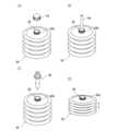
図5(A)は、貯水タンク66を模式的に示す斜視図である。貯水タンク66は、蓋状のコネクターが着脱可能に固定される開口部68を上部に有する。例えば、開口部68の外周面68aには、ネジ溝が形成される。貯水タンク66の使用を開始する前や、貯水タンク66を運搬する際には、開口部68にキャップ94を螺合して該開口部68を閉塞しておき、貯水タンク66の内部の汚染を防止する。そして、貯水タンク66の使用を開始する際には、図5(A)に示す通り、キャップ94を外しておく。Figure 5 (A) is a perspective view showing a schematic of the
純水生成装置64で浄化される水は、予め貯水タンク66に収容された状態で該純水生成装置64に運搬されてもよい。図5(B)は、貯水タンク66に浄化の対象となる水を入れる様子を模式的に示す斜視図である。貯水タンク66に水を入れる際には、例えば、送水管96を開口部68に挿し入れる。そして、該送水管96を介して水を貯水タンク66に注入する。The water to be purified in the pure
次に、図5(C)に示すようにコネクター98を貯水タンク66の開口部68に取り付ける。貯水タンク66から純水生成装置64への水の送り出しと、貯水タンク66への水の再注入と、の同時作業はコネクター98により実現される。次に、コネクター98について詳述する。Next, as shown in FIG. 5(C), the
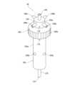
図6は、蓋状のコネクター98を模式的に示す斜視図である。また、図7及び図8は、コネクター98を模式的に示す断面図である。コネクター98は、貯水タンク66の開口部68に螺合される蓋部100と、コネクター98が該開口部68に装着された際に貯水タンク66の外部に露出される頭部102と、貯水タンク66の内部に収容される突出部104と、を備える。蓋部100の外周面100aには、該蓋部100を回転させる作業者の手の滑り抑制する凹凸が形成される。Figure 6 is a perspective view showing a lid-shaped
蓋部100は、開口部68の径に対応した径の凹部を有する。該凹部の内周面100bには、開口部68の外周面68aに形成されたネジ溝に螺合できるネジ山が形成されている。蓋部100を開口部68に螺合することで、コネクター98を貯水タンク66に装着できる。このとき、コネクター98で貯水タンク66が密閉される。なお、貯水タンク66は密閉容器であり、開口部68にコネクター98が装着されたときに汚染源となる空気が外部から侵入できない状態となる。The
コネクター98を開口部68に装着したとき、円柱状の頭部102が貯水タンク66の外部に露出する。頭部102には、各種の配管等が接続される。コネクター98は、ポンプ56,72に接続し、貯水タンク66に貯水された水を送り出す経路となる主ポート106を頭部102に備える。すなわち、主ポート106にはチューブ等で形成された流路48a,70が接続される。そして、ポンプ56,72で生じた負圧は、流路48a,70及び主ポート106を通じて貯水タンク66に貯水された水に作用する。When the
また、コネクター98の頭部102には、ポンプ56,72で送り出された水が貯水タンク66の内部に戻される際の流入口となる戻しポートが設けられる。例えば、頭部102の外周面102aには、第1の戻しポート108aと、第2の戻しポート108bと、第3の戻しポート108cと、第4の戻しポート108dと、が設けられる。The
例えば、図3に示される純水生成装置2aにおいては、第1の戻しポート108aには第1の戻し経路62aが接続され、第2の戻しポート108bには第2の戻し経路62bが接続される。また、第3の戻しポート108cには第3の戻し経路62dが接続され、第4の戻しポート108dには第4の戻し経路62eが接続される。コネクター98は、さらに、第5の戻し経路62cが接続される第5の戻しポート(不図示)が頭部102に設けられてもよい。For example, in the pure
また、図4に示される純水生成装置64においては、第1の戻しポート108aには第1の戻し経路90aが接続され、第2の戻しポート108bには第2の戻し経路90bが接続される。また、第3の戻しポート108cには第3の戻し経路90cが接続され、第4の戻しポート108dには第4の戻し経路90dが接続される。また、図2に示される純水生成装置2においては、いずれかの戻しポートに戻し経路54が接続され、他の戻しポートには、キャップ等の閉塞具(不図示)が装着される。In the pure
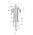
コネクター98は、貯水タンク66の開口部68にコネクター98が固定されたときに貯水タンク66の内部に突き出る円柱状の突出部104を備える。図7は、コネクター98の断面を模式的に示す断面図である。図7に示す通り、コネクター98は、一端が主ポート106に接続され、他端が突出部104の外面に形成された吸水口112に接続された吸水路110を内部に備える。The
ポンプ56,72は、貯水タンク66に貯水された水を吸水口112から吸い込み、吸水路110を通じて該水を貯水タンク66の外部に吸い出す。貯水タンク66に貯水された水の水位が低い場合においても該水を吸い出せるように、吸水口112は、突出部104の最下部に形成されているとよい。The
図8は、図7とは異なる面でコネクター98を切断したときに現れる断面を模式的に示す断面図である。図8に示す通り、コネクター98は、一端が第1の戻しポート108aに接続され、他端が突出部104の外面に形成された注水口120aに接続された注水路122aを内部に備える。また、コネクター98は、一端が第3の戻しポート108cに接続され、他端が突出部104の外面に形成された注水口120cに接続された注水路122cを内部に備える。Figure 8 is a cross-sectional view that shows a schematic cross section that appears when the
すなわち、コネクター98は、各戻しポート108a,108b,108c,108dに接続された注水路122a,122cを内部に有し、それぞれの注水路122a,122cの出口となる注水口120a,120b,120cを突出部104の外面に備える。なお、コネクター98の内部では、各注水路122a,122cが合流されてもよく、コネクター98の突出部104の外面には、一つの注水口が形成されてもよい。That is, the
また、各注水口120a,120b,120cは、例えば、蓋部100と、吸水口112と、の間の高さ位置で突出部104の外周面104aに形成されるとよい。そして、水を貯水する貯水タンク66にコネクター98が固定されたとき、該水の中に注水口120a,120b,120cに沈むことが好ましい。この場合、注水口120a,120b,120cから貯水タンク66に注水される流入水が該水の上面に降り注いで該上面を泡立てることがなく、該水が泡立つことによる該水の汚染を抑制できる。In addition, each of the
貯水タンク66に外部から気体が侵入して滞留すると、該気体中に舞う塵や微生物等が貯水タンク66に貯水されている水に混入したり、また、該気体の一部の成分が該水に溶解したりするため、該気体が該水を汚染させる原因となる。そこで、コネクター98は、コネクター98は、貯水タンク66の内部に侵入した気体を外部に逃がすための排気機構を備えるとよい。When gas enters the
例えば、図7等に示す通り、コネクター98は、突出部104の外面に形成された吸気口114と、頭部102の外面に形成された排気口116と、一端が吸気口114に接続され他端が排気口116に接続された排気路118と、を備える。すなわち、排気口116は、貯水タンク66の開口部68にコネクター98が固定されたときに貯水タンク66の外部に露出する。このとき、吸気口114は、貯水タンク66の内部空間に露出する。7, the
排気口116は、外部から塵等が侵入しにくいように頭部102の外周面102aに水平方向に向けて形成されているとよい。そして、排気口116への塵等の侵入を防止すフィルターが該排気口116に装着されていてもよい。さらに、該排気機構には、気体の逆流を防止する逆流防止弁が設けられてもよい。The
吸気口114は、吸水口112よりも主ポート106に近い位置で突出部104の外面に形成されているとよい。特に、注水口120a,120b,120cよりも蓋部100に近い位置で突出部104の外周面104aに形成されていることが好ましい。貯水タンク66の内部では気体が上方に溜まるため、吸気口114の形成位置が蓋部100に近いほど気体の排出に有利となる。The
ここで、貯水タンク66に貯水される水の量は一定ではなく増減する。貯水タンク66の容量が一定である場合、貯水タンク66の内部の水の量が減ったときに該水が占めていた空間を埋めるように貯水タンク66の内部に気体が侵入し、該気体により水が汚染されるため問題となる。Here, the amount of water stored in the
そこで、貯水タンク66は変形可能であるとよく、内部に貯水された水の量に応じて変形することにより容量を増減できるとよい。図5(D)は、容量が変化した貯水タンク6を模式的に示す斜視図である。例えば、貯水タンク66は、蛇腹構造を胴体部に有し、内部に貯水された水の量に従って蛇腹が伸縮するとよい。または、貯水タンク66は、柔軟な樹脂シート等で袋状に形成されていてもよい。Therefore, it is preferable that the
貯水タンク66が密閉容器であり、かつ、変形可能であると、内部に貯水された水の量が変化したときに外部から気体が侵入できるような空間が該貯水タンク66の内部に形成されないように該貯水タンク66が変形できるため、水の汚染を防止できる。If the
なお、本実施形態に係る純水生成装置64には、変形可能な貯水タンク66に収容された水の量を監視するために、移動可能なプローブを備える接触式のセンサー等が設けられてもよい。例えば、貯水タンク66が大きくなるときに該貯水タンク66に接触する該プローブが移動することで貯水タンク66に収容された水の量に関する情報を得てもよい。The pure
または、貯水タンク66の内部に収容された水の量は、他の方法により監視されてもよい。例えば、純水生成装置64は、貯水タンク66の収容位置に、該貯水タンク66が載る重量計を備えてもよい。そして、重量計が測定する貯水タンク66の重量により貯水された水の量を監視してもよい。貯水タンク66に収容された水の量を監視すると、貯水タンク66の収容能力を超えた水が貯水タンク66に進入するのを防止できる。Alternatively, the amount of water contained inside the
なお、収容能力の限界まで貯水タンク66に水が進入している場合、貯水タンク66から外部に水が捨てられてもよい。例えば、貯水タンク66の内外の空間を接続する排気機構を利用すると水を貯水タンク66の外部に排出できる。例えば、余剰な水を吸気口114から排気路118を経て排気口116まで水を移動させ、該排気口116から噴出させることで該水を外部に排出できる。When water has entered the
この場合、排気機構は、貯水タンク66の収容能力の限界を超えて水が貯水タンク66に供給されたとき、自動的に余剰な水が外部に進行することで貯水タンク66の破損を防止する安全装置として機能できる。In this case, the exhaust mechanism can function as a safety device that prevents damage to the
以上に説明する通り、本実施形態に係る純水生成装置2,2a,64によると、貯水タンク6,66との間で水を循環させつつ、該純水生成装置2,2a,64の各部で該水を十分に浄化できる。そのため、不純物の極めて少ない純水を生成できる。As described above, the pure
なお、上記実施形態では、純水生成装置2,2a,64が、第1の濾過部14,82と、紫外線照射ユニット30,84と、イオン交換ユニット32,86と、第2の濾過部34,88と、を備える場合について説明したが、本発明の一態様はこれに限定されない。例えば、純水生成装置2,2a,64は、一部の構成要素が省略されていてもよく、水を浄化するためのさらに他の構成要素を備えてもよい。In the above embodiment, the pure
本発明の一態様に係る純水生成装置2,2a,64は、各構成要素の一つへの水の流入を規制できるバルブと、該バルブにより規制された水が貯水タンクに戻るための経路となる戻し経路と、を有する。そのため、当該構成要素において水を十分に浄化でき、所定の基準に満たない清浄度の水が下流の構成要素に流入することはなく、所定の基準に満たない清浄度の水が純水生成装置2,2a,64から排出されることもない。The pure
また、上記実施形態では、純水生成装置2,2aが、4つ以上のバルブと、該バルブにより規制された水が貯水タンク6に戻る経路となる4つ以上の戻し経路と、を有する場合について説明した。しかしながら、本発明の一態様はこれに限定されない。すなわち、本発明の一態様に係る純水生成装置2,2aは、バルブ及び戻し経路を1組以上3組以下の数で有してもよい。In the above embodiment, the pure
例えば、純水生成装置2,2aは、第1の濾過部14と、紫外線照射ユニット30と、イオン交換ユニット32と、第2の濾過部34と、のいずれか一つへの水の流入を規制できる少なくとも一つのバルブを有していればよい。そして、該バルブにより規制された水が貯水タンク6に戻るための経路となる少なくとも一つの戻し経路を有していればよい。この場合においても、純水生成装置2,2aの特定の構成要素に清浄度の低い水が流れるのを防止でき、該特定の構成要素における問題の発生を抑制できる。For example, the pure
その他、上記実施形態に係る構造、方法等は、本発明の目的の範囲を逸脱しない限りにおいて適宜変更して実施できる。In addition, the structures, methods, etc. according to the above embodiments can be modified as appropriate without departing from the scope of the present invention.
2,2a,64 純水生成装置
4 給水路
6,66 貯水タンク
8,98 コネクター
10,26 ガイドレール
12,28 受け皿(パン)
14,82 第1の濾過部
16 排水路
20 ホース
22 支持板
24 清水タンク
30,84 紫外線照射ユニット
32,86 イオン交換ユニット
32a,32b イオン交換樹脂部
34,88 第2の濾過部
36 流出路
38 枠体
40 純水タンク
42,92 制御ユニット
44 表示部
46 入力部
48a,48b,48c,48d,48e,48f,48f,70 流路
50a,50b,50c,50d,50e バルブ
52a,52b,52c,52d,52e,54 戻し経路
56,72 ポンプ
58,74 パーティクルカウンター
60,76 比抵抗値センサー
62a,62b,62c,62d,62e 戻し経路
68 開口部
68a 外周面
78 主流路
80a,80b,80c,80d バルブ
90a,90b,90c,90d 戻し経路
94 キャップ
96 送水管
100 蓋部
100a,102a,104a 外周面
100b 内周面
102 頭部
104 突出部
106 主ポート
108a,108b,108c,108d 戻しポート
110 吸水路
112 吸水口
114 吸気口
116 排気口
118 排気路
120a,120b,120c 注水口
122a,122c 注水路 2, 2a, 64 Pure water generating device 4
Claims (14)
Translated fromJapanese水を貯水する貯水タンクと、
該貯水タンクに連通し、該貯水タンクから水を送り出すポンプと、
該ポンプにより該貯水タンクから送り出された水を濾過する第1の濾過部と、
該第1の濾過部で濾過された水に紫外線を照射して該水に含まれる有機物を破壊する紫外線照射ユニットと、
該紫外線照射ユニットにより紫外線が照射された水に含まれる不純物イオンを交換するイオン交換ユニットと、
該イオン交換ユニットで不純物イオンが除去された水を濾過する第2の濾過部と、
該第1の濾過部と、該紫外線照射ユニットと、該イオン交換ユニットと、該第2の濾過部と、のいずれか一つである下流への水の流入を規制できるバルブと、
該貯水タンクに接続されており、該バルブにより規制された水が該貯水タンクに戻るための経路となる戻し経路と、
を備え、
該バルブにより規制された水は、該下流に流れないことを特徴とする純水生成装置。 A pure water generating apparatus for generating pure water,
A water tank for storing water;
a pump communicating with the water storage tank and pumping water from the water storage tank;
a first filtering unit that filters the water pumped out from the water storage tank by the pump;
an ultraviolet irradiation unit that irradiates the water filtered by the first filtration unit with ultraviolet rays to destroy organic matter contained in the water;
an ion exchange unit that exchanges impurity ions contained in the water irradiated with ultraviolet light by the ultraviolet irradiation unit;
a second filtration section that filters the water from which the impurity ions have been removed by the ion exchange unit;
a valve capable of regulating the inflow of waterdownstream of any one of the first filtration unit, the ultraviolet irradiation unit, the ion exchange unit, and the second filtration unit;
a return path connected to the water tank for allowing the water regulated by the valve to return to the water tank;
Equippedwith
The pure water generating apparatus is characterized in thatthe water restricted by the valve does not flow downstream .
水を貯水する貯水タンクと、
該貯水タンクに連通し水を送り出すポンプと、
該ポンプにより該貯水タンクから送り出された水を濾過する第1の濾過部と、
該第1の濾過部に連通し、該第1の濾過部で濾過された水に紫外線を照射して該水に含まれる有機物を破壊する紫外線照射ユニットと、
該紫外線照射ユニットに連通し、該紫外線照射ユニットにより紫外線が照射された水に含まれる不純物イオンを交換するイオン交換ユニットと、
該イオン交換ユニットに連通し、該イオン交換ユニットで不純物イオンが除去された水を濾過する第2の濾過部と、
該第1の濾過部から該紫外線照射ユニットへの水の流出を規制できる第1のバルブと、
該紫外線照射ユニットから該イオン交換ユニットへの水の流出を規制できる第2のバルブと、
該イオン交換ユニットから該第2の濾過部への水の流出を規制できる第3のバルブと、
該第2の濾過部からの流出する水を規制できる第4のバルブと、
該第1のバルブで該第1の濾過部から該紫外線照射ユニットへの流出が規制された水を該貯水タンクに戻す第1の戻し経路と、
該第2のバルブで該紫外線照射ユニットから該イオン交換ユニットへの流出が規制された水を該貯水タンクに戻す第2の戻し経路と、
該第3のバルブで該イオン交換ユニットから該第2の濾過部への流出が規制された水を該貯水タンクに戻す第3の戻し経路と、
該第4のバルブで該第2の濾過部からの流出が規制された水を該貯水タンクに戻す第4の戻し経路と、
該第1のバルブと、該第2のバルブと、該第3のバルブと、該第4のバルブと、制御する制御ユニットと、を備え、
該制御ユニットは、
該第1のバルブで該第1の濾過部から該紫外線照射ユニットへの水の流出を規制して該紫外線照射ユニットに水を流さず、該ポンプと、該第1の濾過部と、該貯水タンクと、を該第1の戻し経路を介して接続して水を循環させる第1の循環モードと、
該第1のバルブで水の流出を規制せず、該第2のバルブで該紫外線照射ユニットから該イオン交換ユニットへの水の流出を規制して該イオン交換ユニットに水を流さず、該ポンプと、該第1の濾過部と、該紫外線照射ユニットと、該貯水タンクと、を該第2の戻し経路を介して接続して水を循環させる第2の循環モードと、
該第1のバルブ及び該第2のバルブで水の流出を規制せず、該第3のバルブで該イオン交換ユニットから該第2の濾過部への水の流出を規制して該第2の濾過部に水を流さず、該ポンプと、該第1の濾過部と、該紫外線照射ユニットと、該イオン交換ユニットと、該貯水タンクと、を該第3の戻し経路を介して接続して水を循環させる第3の循環モードと、
該第1のバルブ、該第2のバルブ、及び該第3のバルブで水の流出を規制せず、該第4のバルブで該第2の濾過部からの水の流出を規制して該第2の濾過部から下流に水を流さず、該ポンプと、該第1の濾過部と、該紫外線照射ユニットと、該イオン交換ユニットと、該第2の濾過部と、該貯水タンクと、を該第4の戻し経路を介して接続して水を循環させる第4の循環モードと、
に切り替え可能であることを特徴とする純水生成装置。 A pure water generating apparatus for generating pure water,
A water tank for storing water;
A pump communicating with the water storage tank for pumping water;
a first filtering unit that filters the water pumped out from the water storage tank by the pump;
an ultraviolet irradiation unit communicating with the first filtration section and irradiating the water filtered by the first filtration section with ultraviolet light to destroy organic matter contained in the water;
an ion exchange unit communicating with the ultraviolet irradiation unit and exchanging impurity ions contained in the water irradiated with ultraviolet rays by the ultraviolet irradiation unit;
a second filtration section that communicates with the ion exchange unit and filters the water from which the impurity ions have been removed by the ion exchange unit;
a first valve capable of regulating the outflow of water from the first filtration section to the ultraviolet irradiation unit;
a second valve capable of regulating the outflow of water from the ultraviolet irradiation unit to the ion exchange unit;
a third valve capable of regulating the outflow of water from the ion exchange unit to the second filtration section;
a fourth valve capable of regulating the flow of water out of the second filtration unit;
a first return path for returning the water, the outflow of which from the first filtration section to the ultraviolet irradiation unit is restricted by the first valve, to the water storage tank;
a second return path for returning the water, the outflow of which from the ultraviolet irradiation unit to the ion exchange unit is restricted by the second valve, to the water storage tank;
a third return path for returning the water, the outflow of which from the ion exchange unit to the second filtration section is restricted by the third valve, to the water storage tank;
a fourth return path that returns the water, the outflow of which is restricted from the second filtration unit by the fourth valve, to the water storage tank;
a control unit for controlling the first valve, the second valve, the third valve, and the fourth valve;
The control unit
a first circulation mode in which the first valve regulates the outflow of water from the first filtration section to the ultraviolet irradiation unitto prevent water from flowing into the ultraviolet irradiation unit , and the pump, the first filtration section, and the water storage tank are connected via the first return path to circulate water;
a second circulation mode in which the first valve is not used to regulate the outflow of water, the second valve is used to regulate the outflow of water from the ultraviolet irradiation unit to the ionexchange unit so that water does not flow into the ion exchange unit , and the pump, the first filtration section, the ultraviolet irradiation unit, and the water storage tank are connected via the second return path to circulate water;
a third circulation mode in which the first valve and the second valve do not regulate the outflow of water, the third valve regulates the outflow of water from the ion exchange unit to the second filtration sectionso that water does not flow into the second filtration section , and the pump, the first filtration section, the ultraviolet irradiation unit, the ion exchange unit, and the water storage tank are connected via the third return path to circulate water;
a fourth circulation mode in which the first valve, the second valve, and the third valve do not regulate the outflow of water, the fourth valve regulates the outflow of water from the second filtration sectionso that water does not flow downstream from the second filtration section, and the pump, the first filtration section, the ultraviolet irradiation unit, the ion exchange unit, the second filtration section, and the water storage tank are connected via the fourth return path to circulate water;
A pure water generating apparatus characterized in that it can be switched between
該第1のイオン交換樹脂部から該第2のイオン交換樹脂部への水の流出を規制できる第5のバルブと、
該第5のバルブで該第1のイオン交換樹脂部から該第2のイオン交換樹脂部への流出が規制された水を該貯水タンクに戻す第5の戻し経路と、をさらに有し、
該制御ユニットは、さらに、該第5のバルブで該第1のイオン交換樹脂部から該第2のイオン交換樹脂部への水の流出を規制して該第2のイオン交換樹脂部に水を流さず、該ポンプと、該第1の濾過部と、該紫外線照射ユニットと、該イオン交換ユニットの該第1のイオン交換樹脂部と、を該第5の戻し経路を介して接続して水を循環させる第5の循環モードに切り替えられることを特徴とする請求項2に記載の純水生成装置。 The ion exchange unit has a first ion exchange resin section and a second ion exchange resin section connected to the first ion exchange resin section,
a fifth valve capable of regulating the outflow of water from the first ion exchange resin portion to the second ion exchange resin portion; and
a fifth return path for returning the water, the outflow of which from the first ion exchange resin part to the second ion exchange resin part is restricted by the fifth valve, to the water storage tank;
The pure water generating apparatus of claim 2, further characterized in that the control unit can be switched to a fifth circulation mode in which the fifth valve regulates the outflow of water from the first ion exchange resin sectionto the second ion exchange resin section so as not to allow water to flow through the second ion exchange resin section, and the pump, the first filtration section, the ultraviolet irradiation unit, and the first ion exchange resin section of the ion exchange unit are connected via the fifth return path to circulate water.
水を貯水する貯水タンクと、
該貯水タンクに連通し水を送り出すポンプと、
該ポンプから送り出された水の流路となる主流路と、
第1のバルブを介して該主流路に接続され、該主流路から供給された水を濾過し、第1の戻し経路を介して該水を該貯水タンクに戻す第1の濾過部と、
第2のバルブを介して該主流路に接続され、該主流路から供給された水に紫外線を照射して該水に含まれる有機物を破壊し、第2の戻し経路を介して該水を該貯水タンクに戻す紫外線照射ユニットと、
第3のバルブを介して該主流路に接続され、該主流路から供給された水に含まれる不純物イオンを交換し、第3の戻し経路を介して該水を該貯水タンクに戻すイオン交換ユニットと、
第4のバルブを介して該主流路に接続され、該主流路から供給された水を濾過し、第4の戻し経路を介して該水を該貯水タンクに戻す第2の濾過部と、
該第1のバルブと、該第2のバルブと、該第3のバルブと、該第4のバルブと、を制御できる制御ユニットと、を備え、
該制御ユニットは、
該第1のバルブを開にし、該第2のバルブ、該第3のバルブ、及び該第4のバルブを閉にして、該紫外線照射ユニットと、該イオン交換ユニットと、該第2の濾過部と、に水を流さず、該第1の濾過部及び該貯水タンクに該第1の戻し経路及び該主流路を介して水を循環させる第1の循環モードと、
該第2のバルブを開にし、該第1のバルブ、該第3のバルブ、及び該第4のバルブを閉にして、該第1の濾過部と、該イオン交換ユニットと、該第2の濾過部と、に水を流さず、該紫外線照射ユニット及び該貯水タンクに該第2の戻し経路及び該主流路を介して水を循環させる第2の循環モードと、
該第3のバルブを開にし、該第1のバルブ、該第2のバルブ、及び該第4のバルブを閉にして、該第1の濾過部と、該紫外線照射ユニットと、該第2の濾過部と、に水を流さず、該イオン交換ユニット及び該貯水タンクに該第3の戻し経路及び該主流路を介して水を循環させる第3の循環モードと、
該第4のバルブを開にし、該第1のバルブ、該第2のバルブ、及び該第3のバルブを閉にして、該第1の濾過部と、該紫外線照射ユニットと、該イオン交換ユニットと、に水を流さず、該第2の濾過部及び該貯水タンクに該第4の戻し経路及び該主流路を介して水を循環させる第4の循環モードと、
を切り替え可能であることを特徴とする純水生成装置。 A pure water generating apparatus for generating pure water,
A water tank for storing water;
A pump communicating with the water storage tank for pumping water;
A main flow path that serves as a flow path for water pumped out from the pump;
a first filtering unit connected to the main flow path via a first valve, filtering water supplied from the main flow path, and returning the water to the water storage tank via a first return path;
an ultraviolet irradiation unit connected to the main flow path via a second valve, which irradiates the water supplied from the main flow path with ultraviolet light to destroy organic matter contained in the water, and returns the water to the water storage tank via a second return path;
an ion exchange unit connected to the main flow path via a third valve, exchanging impurity ions contained in the water supplied from the main flow path, and returning the water to the water storage tank via a third return path;
a second filtration unit connected to the main flow path via a fourth valve, filtering water supplied from the main flow path, and returning the water to the water storage tank via a fourth return path;
a control unit capable of controlling the first valve, the second valve, the third valve, and the fourth valve;
The control unit
a first circulation mode in which the first valve is opened, and the second valve, the third valve, and the fourth valve are closedto prevent water from flowing through the ultraviolet irradiation unit, the ion exchange unit, and the second filtration unit, and water is circulated through the first filtration unit and the water storage tank via the first return path and the main flow path;
a second circulation mode in which the second valve is opened, and the first valve, the third valve, and the fourth valve are closedto prevent water from flowing through the first filtration unit, the ion exchange unit, and the second filtration unit, and water is circulated through the ultraviolet irradiation unit and the water storage tank via the second return path and the main flow path;
a third circulation mode in which the third valve is opened, and the first valve, the second valve, and the fourth valve are closedto prevent water from flowing through the first filtration unit, the ultraviolet irradiation unit, and the second filtration unit, and water is circulated through the ion exchange unit and the water storage tank via the third return path and the main flow path;
a fourth circulation mode in which the fourth valve is opened, and the first valve, the second valve, and the third valve are closedto prevent water from flowing through the first filtration unit, the ultraviolet irradiation unit, and the ion exchange unit, and water is circulated through the second filtration unit and the water storage tank via the fourth return path and the main flow path;
A pure water generating apparatus characterized in that the above-mentioned can be switched.
該コネクターは、該ポンプに接続し、該貯水タンクに貯水された水を送り出す経路となる主ポートを備えることを特徴とする請求項1に記載の純水生成装置。 The water tank has an opening to which a lid-shaped connector is removably fixed,
2. The pure water generating apparatus according to claim 1, wherein the connector includes a main port which is connected to the pump and serves as a path for delivering the water stored in the water storage tank.
該コネクターは、該ポンプに接続し、該貯水タンクに貯水された水を送り出す経路となる主ポートを備えることを特徴とする請求項2乃至請求項4のいずれかに記載の純水生成装置。 The water tank has an opening to which a lid-shaped connector is removably fixed,
5. The pure water generating apparatus according to claim 2, wherein the connector is provided with a main port which is connected to the pump and serves as a path for delivering the water stored in the water storage tank.
該第1の戻し経路に接続する第1の戻しポートと、
該第2の戻し経路に接続する第2の戻しポートと、
該第3の戻し経路に接続する第3の戻しポートと、
該第4の戻し経路に接続する第4の戻しポートと、
をさらに備えることを特徴とする請求項6に記載の純水生成装置。 The connector comprises:
a first return port connected to the first return path;
a second return port connected to the second return path;
a third return port connected to the third return path;
a fourth return port connected to the fourth return path;
The pure water generating apparatus according to claim 6, further comprising:
該貯水タンクの該開口部に該コネクターが固定されたときに該貯水タンクの内部に突き出る突出部と、
一端が該主ポートに接続され、他端が該突出部の外面に形成された吸水口に接続された吸水路と、
該吸水口よりも該主ポートに近い位置で該突出部の該外面に形成された吸気口と、
該貯水タンクの該開口部に該コネクターが固定されたときに該貯水タンクの外部に露出する排気口と、
一端が該吸気口に接続され、他端が該排気口に接続された排気路と、
をさらに備えることを特徴とする請求項5乃至請求項7のいずれかに記載の純水生成装置。 The connector comprises:
a protrusion that protrudes into the water tank when the connector is fixed to the opening of the water tank;
a water intake passage having one end connected to the main port and the other end connected to a water intake port formed on the outer surface of the protrusion;
an air intake port formed on the outer surface of the protrusion at a position closer to the main port than the water intake port;
an exhaust port that is exposed to the outside of the water tank when the connector is fixed to the opening of the water tank;
an exhaust passage having one end connected to the intake port and the other end connected to the exhaust port;
8. The pure water generating apparatus according to claim 5, further comprising:
該貯水タンクに戻される水、または、該ポンプにより該貯水タンクから送り出された水の比抵抗値を測定する比抵抗値センサーと、
の一方または両方をさらに備えることを特徴とする請求項1乃至請求項8のいずれかに記載の純水生成装置。 a particle counter for counting particles contained in the water returned to the water storage tank or the water pumped out of the water storage tank by the pump;
a resistivity sensor for measuring the resistivity of the water returned to the water storage tank or the water pumped out of the water storage tank by the pump;
9. The pure water generating apparatus according to claim 1, further comprising one or both of the following:
該第2のバルブは、該イオン交換ユニットと、該第2の戻し経路と、の一方に選択的に水を流す三方弁であり、the second valve is a three-way valve that selectively allows water to flow to one of the ion exchange unit and the second return path;
該第3のバルブは、該第2の濾過部と、該第3の戻し経路と、の一方に選択的に水を流す三方弁であり、the third valve is a three-way valve that selectively allows water to flow to one of the second filtering section and the third return path;
該第4のバルブは、該下流と、該第4の戻し経路と、の一方に選択的に水を流す三方弁であることを特徴とする請求項2に記載の純水生成装置。3. The pure water generating apparatus according to claim 2, wherein the fourth valve is a three-way valve that selectively allows water to flow to one of the downstream and the fourth return path.
該第2のバルブは、該イオン交換ユニットと、該第2の戻し経路と、の一方に選択的に水を流す三方弁であり、the second valve is a three-way valve that selectively allows water to flow to one of the ion exchange unit and the second return path;
該第3のバルブは、該第2の濾過部と、該第3の戻し経路と、の一方に選択的に水を流す三方弁であり、the third valve is a three-way valve that selectively allows water to flow to one of the second filtering section and the third return path;
該第4のバルブは、該下流と、該第4の戻し経路と、の一方に選択的に水を流す三方弁であり、the fourth valve is a three-way valve that selectively allows water to flow to one of the downstream and the fourth return path;
該第5のバルブは、該第2のイオン交換樹脂部と、該第5の戻し経路と、の一方に選択的に水を流す三方弁であることを特徴とする請求項3に記載の純水生成装置。4. The pure water generating apparatus according to claim 3, wherein the fifth valve is a three-way valve that selectively allows water to flow to one of the second ion exchange resin section and the fifth return path.
Priority Applications (1)
| Application Number | Priority Date | Filing Date | Title |
|---|---|---|---|
| JP2020116383AJP7466999B2 (en) | 2020-07-06 | 2020-07-06 | Pure Water Generator |
Applications Claiming Priority (1)
| Application Number | Priority Date | Filing Date | Title |
|---|---|---|---|
| JP2020116383AJP7466999B2 (en) | 2020-07-06 | 2020-07-06 | Pure Water Generator |
Publications (2)
| Publication Number | Publication Date |
|---|---|
| JP2022014180A JP2022014180A (en) | 2022-01-19 |
| JP7466999B2true JP7466999B2 (en) | 2024-04-15 |
Family
ID=80185259
Family Applications (1)
| Application Number | Title | Priority Date | Filing Date |
|---|---|---|---|
| JP2020116383AActiveJP7466999B2 (en) | 2020-07-06 | 2020-07-06 | Pure Water Generator |
Country Status (1)
| Country | Link |
|---|---|
| JP (1) | JP7466999B2 (en) |
Citations (7)
| Publication number | Priority date | Publication date | Assignee | Title |
|---|---|---|---|---|
| JP2000263043A (en) | 1999-03-19 | 2000-09-26 | Dai Ichi Seiyaku Co Ltd | Purified water production storage system |
| JP2004275881A (en) | 2003-03-14 | 2004-10-07 | Kurita Water Ind Ltd | Ultrapure water production system |
| US20110257788A1 (en) | 2007-08-01 | 2011-10-20 | Wiemers Reginald A | Mobile station and methods for diagnosing and modeling site specific full-scale effluent treatment facility requirements |
| JP2013215679A (en) | 2012-04-09 | 2013-10-24 | Nomura Micro Sci Co Ltd | Ultrapure water production apparatus |
| CN203999228U (en) | 2014-06-23 | 2014-12-10 | 溢通环保科技(莆田)有限公司 | The preparation system of automobile-used urea production ultrapure water used |
| JP2015096254A (en) | 2013-11-15 | 2015-05-21 | 株式会社ディスコ | Pure water purification apparatus |
| JP2018144032A (en) | 2017-03-06 | 2018-09-20 | ベー・ブラウン・アヴィトゥム・アー・ゲーB. Braun Avitum Ag | Water treatment system |
Family Cites Families (4)
| Publication number | Priority date | Publication date | Assignee | Title |
|---|---|---|---|---|
| JPH05140799A (en)* | 1991-07-09 | 1993-06-08 | Masayuki Otsuki | Sterilizer |
| JPH05138196A (en)* | 1991-11-20 | 1993-06-01 | Hitachi Plant Eng & Constr Co Ltd | High-purity ultrapure water production system and water quality control method |
| JPH0679273A (en)* | 1992-09-02 | 1994-03-22 | Hitachi Plant Eng & Constr Co Ltd | Ultrapure water production equipment |
| JP3223660B2 (en)* | 1993-08-30 | 2001-10-29 | 日本マイクロリス株式会社 | Pylogien-free ultrapure water production method |
- 2020
- 2020-07-06JPJP2020116383Apatent/JP7466999B2/enactiveActive
Patent Citations (7)
| Publication number | Priority date | Publication date | Assignee | Title |
|---|---|---|---|---|
| JP2000263043A (en) | 1999-03-19 | 2000-09-26 | Dai Ichi Seiyaku Co Ltd | Purified water production storage system |
| JP2004275881A (en) | 2003-03-14 | 2004-10-07 | Kurita Water Ind Ltd | Ultrapure water production system |
| US20110257788A1 (en) | 2007-08-01 | 2011-10-20 | Wiemers Reginald A | Mobile station and methods for diagnosing and modeling site specific full-scale effluent treatment facility requirements |
| JP2013215679A (en) | 2012-04-09 | 2013-10-24 | Nomura Micro Sci Co Ltd | Ultrapure water production apparatus |
| JP2015096254A (en) | 2013-11-15 | 2015-05-21 | 株式会社ディスコ | Pure water purification apparatus |
| CN203999228U (en) | 2014-06-23 | 2014-12-10 | 溢通环保科技(莆田)有限公司 | The preparation system of automobile-used urea production ultrapure water used |
| JP2018144032A (en) | 2017-03-06 | 2018-09-20 | ベー・ブラウン・アヴィトゥム・アー・ゲーB. Braun Avitum Ag | Water treatment system |
Also Published As
| Publication number | Publication date |
|---|---|
| JP2022014180A (en) | 2022-01-19 |
Similar Documents
| Publication | Publication Date | Title |
|---|---|---|
| JP5461918B2 (en) | Processing waste liquid treatment equipment | |
| KR101385365B1 (en) | Process liquid waste treatment apparatus | |
| JP2009214193A (en) | Processing waste liquid treatment device | |
| JP7343325B2 (en) | Waste liquid treatment equipment | |
| JP7068050B2 (en) | Pure water recycling system | |
| JP2009545136A (en) | Apparatus and method for conditioning immersion fluid | |
| JP7466999B2 (en) | Pure Water Generator | |
| JP5681029B2 (en) | Processing waste liquid treatment equipment | |
| JP7718857B2 (en) | Cleaning equipment | |
| JP7399564B2 (en) | How to replace ion exchange unit and ion exchange resin | |
| JP5086125B2 (en) | Processing waste liquid treatment equipment | |
| JP7483310B2 (en) | Display System | |
| JP7339033B2 (en) | How to install processing waste liquid treatment equipment | |
| CN112390429B (en) | Processing liquid circulation device | |
| US20240294404A1 (en) | Water supply system | |
| JP5086124B2 (en) | Processing waste liquid treatment equipment | |
| JP2012218095A (en) | Waste liquid processing device | |
| JP2022109399A (en) | Pure water generator and UV irradiation unit | |
| JP2009285819A (en) | Medicinal solution receiving member, and apparatus and method for collecting medicinal solution | |
| US11319214B2 (en) | Waste liquid treating apparatus | |
| JP7618444B2 (en) | Pure Water Generator | |
| TWI853130B (en) | Wastewater treatment equipment and processed water regeneration system | |
| JP2021122794A (en) | Water circulation device | |
| JP6022765B2 (en) | Liquid management system | |
| JP2009026881A (en) | Liquid reuse system for immersion exposure |
Legal Events
| Date | Code | Title | Description |
|---|---|---|---|
| A621 | Written request for application examination | Free format text:JAPANESE INTERMEDIATE CODE: A621 Effective date:20230525 | |
| A977 | Report on retrieval | Free format text:JAPANESE INTERMEDIATE CODE: A971007 Effective date:20231213 | |
| A131 | Notification of reasons for refusal | Free format text:JAPANESE INTERMEDIATE CODE: A131 Effective date:20231219 | |
| A521 | Request for written amendment filed | Free format text:JAPANESE INTERMEDIATE CODE: A523 Effective date:20240116 | |
| TRDD | Decision of grant or rejection written | ||
| A01 | Written decision to grant a patent or to grant a registration (utility model) | Free format text:JAPANESE INTERMEDIATE CODE: A01 Effective date:20240402 | |
| A61 | First payment of annual fees (during grant procedure) | Free format text:JAPANESE INTERMEDIATE CODE: A61 Effective date:20240402 | |
| R150 | Certificate of patent or registration of utility model | Ref document number:7466999 Country of ref document:JP Free format text:JAPANESE INTERMEDIATE CODE: R150 |