JP7465413B2 - System, program and information processing method - Google Patents
System, program and information processing methodDownload PDFInfo
- Publication number
- JP7465413B2 JP7465413B2JP2023535110AJP2023535110AJP7465413B2JP 7465413 B2JP7465413 B2JP 7465413B2JP 2023535110 AJP2023535110 AJP 2023535110AJP 2023535110 AJP2023535110 AJP 2023535110AJP 7465413 B2JP7465413 B2JP 7465413B2
- Authority
- JP
- Japan
- Prior art keywords
- tissue
- image
- energy
- information
- estimated
- Prior art date
- Legal status (The legal status is an assumption and is not a legal conclusion. Google has not performed a legal analysis and makes no representation as to the accuracy of the status listed.)
- Active
Links
Images


Classifications
- A—HUMAN NECESSITIES
- A61—MEDICAL OR VETERINARY SCIENCE; HYGIENE
- A61B—DIAGNOSIS; SURGERY; IDENTIFICATION
- A61B5/00—Measuring for diagnostic purposes; Identification of persons
- A61B5/0093—Detecting, measuring or recording by applying one single type of energy and measuring its conversion into another type of energy
- G—PHYSICS
- G06—COMPUTING OR CALCULATING; COUNTING
- G06V—IMAGE OR VIDEO RECOGNITION OR UNDERSTANDING
- G06V40/00—Recognition of biometric, human-related or animal-related patterns in image or video data
- G06V40/60—Static or dynamic means for assisting the user to position a body part for biometric acquisition
- G06V40/67—Static or dynamic means for assisting the user to position a body part for biometric acquisition by interactive indications to the user
- A—HUMAN NECESSITIES
- A61—MEDICAL OR VETERINARY SCIENCE; HYGIENE
- A61B—DIAGNOSIS; SURGERY; IDENTIFICATION
- A61B17/00—Surgical instruments, devices or methods
- A—HUMAN NECESSITIES
- A61—MEDICAL OR VETERINARY SCIENCE; HYGIENE
- A61B—DIAGNOSIS; SURGERY; IDENTIFICATION
- A61B18/00—Surgical instruments, devices or methods for transferring non-mechanical forms of energy to or from the body
- A61B18/04—Surgical instruments, devices or methods for transferring non-mechanical forms of energy to or from the body by heating
- A61B18/12—Surgical instruments, devices or methods for transferring non-mechanical forms of energy to or from the body by heating by passing a current through the tissue to be heated, e.g. high-frequency current
- A61B18/14—Probes or electrodes therefor
- A61B18/1442—Probes having pivoting end effectors, e.g. forceps
- A61B18/1445—Probes having pivoting end effectors, e.g. forceps at the distal end of a shaft, e.g. forceps or scissors at the end of a rigid rod
- A—HUMAN NECESSITIES
- A61—MEDICAL OR VETERINARY SCIENCE; HYGIENE
- A61B—DIAGNOSIS; SURGERY; IDENTIFICATION
- A61B34/00—Computer-aided surgery; Manipulators or robots specially adapted for use in surgery
- A61B34/20—Surgical navigation systems; Devices for tracking or guiding surgical instruments, e.g. for frameless stereotaxis
- A—HUMAN NECESSITIES
- A61—MEDICAL OR VETERINARY SCIENCE; HYGIENE
- A61N—ELECTROTHERAPY; MAGNETOTHERAPY; RADIATION THERAPY; ULTRASOUND THERAPY
- A61N7/00—Ultrasound therapy
- A61N7/02—Localised ultrasound hyperthermia
- G—PHYSICS
- G06—COMPUTING OR CALCULATING; COUNTING
- G06T—IMAGE DATA PROCESSING OR GENERATION, IN GENERAL
- G06T7/00—Image analysis
- G06T7/0002—Inspection of images, e.g. flaw detection
- G06T7/0012—Biomedical image inspection
- G—PHYSICS
- G06—COMPUTING OR CALCULATING; COUNTING
- G06T—IMAGE DATA PROCESSING OR GENERATION, IN GENERAL
- G06T7/00—Image analysis
- G06T7/10—Segmentation; Edge detection
- G06T7/11—Region-based segmentation
- G—PHYSICS
- G06—COMPUTING OR CALCULATING; COUNTING
- G06T—IMAGE DATA PROCESSING OR GENERATION, IN GENERAL
- G06T7/00—Image analysis
- G06T7/70—Determining position or orientation of objects or cameras
- G06T7/73—Determining position or orientation of objects or cameras using feature-based methods
- G—PHYSICS
- G06—COMPUTING OR CALCULATING; COUNTING
- G06V—IMAGE OR VIDEO RECOGNITION OR UNDERSTANDING
- G06V10/00—Arrangements for image or video recognition or understanding
- G06V10/20—Image preprocessing
- G06V10/25—Determination of region of interest [ROI] or a volume of interest [VOI]
- G—PHYSICS
- G16—INFORMATION AND COMMUNICATION TECHNOLOGY [ICT] SPECIALLY ADAPTED FOR SPECIFIC APPLICATION FIELDS
- G16H—HEALTHCARE INFORMATICS, i.e. INFORMATION AND COMMUNICATION TECHNOLOGY [ICT] SPECIALLY ADAPTED FOR THE HANDLING OR PROCESSING OF MEDICAL OR HEALTHCARE DATA
- G16H20/00—ICT specially adapted for therapies or health-improving plans, e.g. for handling prescriptions, for steering therapy or for monitoring patient compliance
- G16H20/40—ICT specially adapted for therapies or health-improving plans, e.g. for handling prescriptions, for steering therapy or for monitoring patient compliance relating to mechanical, radiation or invasive therapies, e.g. surgery, laser therapy, dialysis or acupuncture
- G—PHYSICS
- G16—INFORMATION AND COMMUNICATION TECHNOLOGY [ICT] SPECIALLY ADAPTED FOR SPECIFIC APPLICATION FIELDS
- G16H—HEALTHCARE INFORMATICS, i.e. INFORMATION AND COMMUNICATION TECHNOLOGY [ICT] SPECIALLY ADAPTED FOR THE HANDLING OR PROCESSING OF MEDICAL OR HEALTHCARE DATA
- G16H30/00—ICT specially adapted for the handling or processing of medical images
- G16H30/40—ICT specially adapted for the handling or processing of medical images for processing medical images, e.g. editing
- G—PHYSICS
- G16—INFORMATION AND COMMUNICATION TECHNOLOGY [ICT] SPECIALLY ADAPTED FOR SPECIFIC APPLICATION FIELDS
- G16H—HEALTHCARE INFORMATICS, i.e. INFORMATION AND COMMUNICATION TECHNOLOGY [ICT] SPECIALLY ADAPTED FOR THE HANDLING OR PROCESSING OF MEDICAL OR HEALTHCARE DATA
- G16H40/00—ICT specially adapted for the management or administration of healthcare resources or facilities; ICT specially adapted for the management or operation of medical equipment or devices
- G16H40/40—ICT specially adapted for the management or administration of healthcare resources or facilities; ICT specially adapted for the management or operation of medical equipment or devices for the management of medical equipment or devices, e.g. scheduling maintenance or upgrades
- G—PHYSICS
- G16—INFORMATION AND COMMUNICATION TECHNOLOGY [ICT] SPECIALLY ADAPTED FOR SPECIFIC APPLICATION FIELDS
- G16H—HEALTHCARE INFORMATICS, i.e. INFORMATION AND COMMUNICATION TECHNOLOGY [ICT] SPECIALLY ADAPTED FOR THE HANDLING OR PROCESSING OF MEDICAL OR HEALTHCARE DATA
- G16H40/00—ICT specially adapted for the management or administration of healthcare resources or facilities; ICT specially adapted for the management or operation of medical equipment or devices
- G16H40/60—ICT specially adapted for the management or administration of healthcare resources or facilities; ICT specially adapted for the management or operation of medical equipment or devices for the operation of medical equipment or devices
- G16H40/63—ICT specially adapted for the management or administration of healthcare resources or facilities; ICT specially adapted for the management or operation of medical equipment or devices for the operation of medical equipment or devices for local operation
- G—PHYSICS
- G16—INFORMATION AND COMMUNICATION TECHNOLOGY [ICT] SPECIALLY ADAPTED FOR SPECIFIC APPLICATION FIELDS
- G16H—HEALTHCARE INFORMATICS, i.e. INFORMATION AND COMMUNICATION TECHNOLOGY [ICT] SPECIALLY ADAPTED FOR THE HANDLING OR PROCESSING OF MEDICAL OR HEALTHCARE DATA
- G16H50/00—ICT specially adapted for medical diagnosis, medical simulation or medical data mining; ICT specially adapted for detecting, monitoring or modelling epidemics or pandemics
- G16H50/20—ICT specially adapted for medical diagnosis, medical simulation or medical data mining; ICT specially adapted for detecting, monitoring or modelling epidemics or pandemics for computer-aided diagnosis, e.g. based on medical expert systems
- A—HUMAN NECESSITIES
- A61—MEDICAL OR VETERINARY SCIENCE; HYGIENE
- A61B—DIAGNOSIS; SURGERY; IDENTIFICATION
- A61B17/00—Surgical instruments, devices or methods
- A61B2017/0042—Surgical instruments, devices or methods with special provisions for gripping
- A—HUMAN NECESSITIES
- A61—MEDICAL OR VETERINARY SCIENCE; HYGIENE
- A61B—DIAGNOSIS; SURGERY; IDENTIFICATION
- A61B18/00—Surgical instruments, devices or methods for transferring non-mechanical forms of energy to or from the body
- A61B2018/00571—Surgical instruments, devices or methods for transferring non-mechanical forms of energy to or from the body for achieving a particular surgical effect
- A61B2018/00577—Ablation
- A—HUMAN NECESSITIES
- A61—MEDICAL OR VETERINARY SCIENCE; HYGIENE
- A61B—DIAGNOSIS; SURGERY; IDENTIFICATION
- A61B18/00—Surgical instruments, devices or methods for transferring non-mechanical forms of energy to or from the body
- A61B2018/00636—Sensing and controlling the application of energy
- A61B2018/00696—Controlled or regulated parameters
- A61B2018/00702—Power or energy
- A—HUMAN NECESSITIES
- A61—MEDICAL OR VETERINARY SCIENCE; HYGIENE
- A61B—DIAGNOSIS; SURGERY; IDENTIFICATION
- A61B18/00—Surgical instruments, devices or methods for transferring non-mechanical forms of energy to or from the body
- A61B2018/00636—Sensing and controlling the application of energy
- A61B2018/00773—Sensed parameters
- A61B2018/00791—Temperature
- A—HUMAN NECESSITIES
- A61—MEDICAL OR VETERINARY SCIENCE; HYGIENE
- A61B—DIAGNOSIS; SURGERY; IDENTIFICATION
- A61B18/00—Surgical instruments, devices or methods for transferring non-mechanical forms of energy to or from the body
- A61B2018/00636—Sensing and controlling the application of energy
- A61B2018/00898—Alarms or notifications created in response to an abnormal condition
- A—HUMAN NECESSITIES
- A61—MEDICAL OR VETERINARY SCIENCE; HYGIENE
- A61B—DIAGNOSIS; SURGERY; IDENTIFICATION
- A61B5/00—Measuring for diagnostic purposes; Identification of persons
- A61B5/05—Detecting, measuring or recording for diagnosis by means of electric currents or magnetic fields; Measuring using microwaves or radio waves
- A61B5/053—Measuring electrical impedance or conductance of a portion of the body
- A61B5/0538—Measuring electrical impedance or conductance of a portion of the body invasively, e.g. using a catheter
- A—HUMAN NECESSITIES
- A61—MEDICAL OR VETERINARY SCIENCE; HYGIENE
- A61B—DIAGNOSIS; SURGERY; IDENTIFICATION
- A61B5/00—Measuring for diagnostic purposes; Identification of persons
- A61B5/48—Other medical applications
- A61B5/4848—Monitoring or testing the effects of treatment, e.g. of medication
- A—HUMAN NECESSITIES
- A61—MEDICAL OR VETERINARY SCIENCE; HYGIENE
- A61B—DIAGNOSIS; SURGERY; IDENTIFICATION
- A61B5/00—Measuring for diagnostic purposes; Identification of persons
- A61B5/68—Arrangements of detecting, measuring or recording means, e.g. sensors, in relation to patient
- A61B5/6846—Arrangements of detecting, measuring or recording means, e.g. sensors, in relation to patient specially adapted to be brought in contact with an internal body part, i.e. invasive
- A61B5/6847—Arrangements of detecting, measuring or recording means, e.g. sensors, in relation to patient specially adapted to be brought in contact with an internal body part, i.e. invasive mounted on an invasive device
- G—PHYSICS
- G06—COMPUTING OR CALCULATING; COUNTING
- G06T—IMAGE DATA PROCESSING OR GENERATION, IN GENERAL
- G06T2207/00—Indexing scheme for image analysis or image enhancement
- G06T2207/10—Image acquisition modality
- G06T2207/10068—Endoscopic image
- G—PHYSICS
- G06—COMPUTING OR CALCULATING; COUNTING
- G06T—IMAGE DATA PROCESSING OR GENERATION, IN GENERAL
- G06T2207/00—Indexing scheme for image analysis or image enhancement
- G06T2207/20—Special algorithmic details
- G06T2207/20081—Training; Learning
- G—PHYSICS
- G06—COMPUTING OR CALCULATING; COUNTING
- G06T—IMAGE DATA PROCESSING OR GENERATION, IN GENERAL
- G06T2207/00—Indexing scheme for image analysis or image enhancement
- G06T2207/20—Special algorithmic details
- G06T2207/20084—Artificial neural networks [ANN]
- G—PHYSICS
- G06—COMPUTING OR CALCULATING; COUNTING
- G06T—IMAGE DATA PROCESSING OR GENERATION, IN GENERAL
- G06T2207/00—Indexing scheme for image analysis or image enhancement
- G06T2207/30—Subject of image; Context of image processing
- G06T2207/30004—Biomedical image processing
- G06T2207/30024—Cell structures in vitro; Tissue sections in vitro
- G—PHYSICS
- G06—COMPUTING OR CALCULATING; COUNTING
- G06V—IMAGE OR VIDEO RECOGNITION OR UNDERSTANDING
- G06V10/00—Arrangements for image or video recognition or understanding
- G06V10/70—Arrangements for image or video recognition or understanding using pattern recognition or machine learning
- G—PHYSICS
- G06—COMPUTING OR CALCULATING; COUNTING
- G06V—IMAGE OR VIDEO RECOGNITION OR UNDERSTANDING
- G06V2201/00—Indexing scheme relating to image or video recognition or understanding
- G06V2201/03—Recognition of patterns in medical or anatomical images
- G06V2201/031—Recognition of patterns in medical or anatomical images of internal organs
Landscapes
- Engineering & Computer Science (AREA)
- Health & Medical Sciences (AREA)
- Medical Informatics (AREA)
- General Health & Medical Sciences (AREA)
- Public Health (AREA)
- Biomedical Technology (AREA)
- Life Sciences & Earth Sciences (AREA)
- Surgery (AREA)
- Physics & Mathematics (AREA)
- Nuclear Medicine, Radiotherapy & Molecular Imaging (AREA)
- General Physics & Mathematics (AREA)
- Theoretical Computer Science (AREA)
- Animal Behavior & Ethology (AREA)
- Veterinary Medicine (AREA)
- Epidemiology (AREA)
- Primary Health Care (AREA)
- Heart & Thoracic Surgery (AREA)
- Molecular Biology (AREA)
- Radiology & Medical Imaging (AREA)
- Computer Vision & Pattern Recognition (AREA)
- Pathology (AREA)
- Otolaryngology (AREA)
- Plasma & Fusion (AREA)
- Multimedia (AREA)
- General Business, Economics & Management (AREA)
- Business, Economics & Management (AREA)
- Quality & Reliability (AREA)
- Data Mining & Analysis (AREA)
- Databases & Information Systems (AREA)
- Biophysics (AREA)
- Robotics (AREA)
- Urology & Nephrology (AREA)
- Human Computer Interaction (AREA)
- Surgical Instruments (AREA)
- Endoscopes (AREA)
Description
Translated fromJapanese本発明は、システム、プログラム及び情報処理方法等に関する。The present invention relates to a system, a program, an information processing method, etc.
特許文献1には、エネルギーデバイスを用いた手術方法が開示されている。当該手術方法では、CT(Computed Tomography)画像を用いて、焼灼された生体組織の領域と焼灼されていない生体組織の領域をディスプレイに表示させる。そして、次にエネルギーを出力すべき生体組織の領域を医師に提示する。Patent Document 1 discloses a surgical method using an energy device. In this surgical method, CT (Computed Tomography) images are used to display areas of cauterized and uncauterized tissue on a display. The area of tissue to which energy should next be output is then shown to the doctor.
特許文献1に開示される手術方法では、エネルギー出力前とエネルギー出力開始後のCT画像の差分から温度変化を推定する。このため、エネルギー出力開始後に焼灼された生体組織の領域等が表示され、エネルギー出力前に焼灼された生体組織の領域等は表示されない。従って、エネルギー出力の開始前に、エネルギーデバイスによる熱拡散範囲を提示することができないという課題がある。In the surgical method disclosed in Patent Document 1, temperature change is estimated from the difference between CT images before and after the start of energy output. As a result, areas of biological tissue that have been cauterized after the start of energy output are displayed, but areas of biological tissue that have been cauterized before energy output are not displayed. Therefore, there is a problem in that it is not possible to present the range of thermal diffusion by the energy device before the start of energy output.
本開示の一態様は、エネルギー供給を受けてエネルギー出力を行う少なくとも1つのエネルギーデバイス及び少なくとも1つの生体組織が撮像された画像である学習用デバイス組織画像又は前記少なくとも1つの生体組織が撮像された画像である学習用組織画像から、前記エネルギーデバイスからの熱が到達する範囲である熱拡散領域を出力するように学習した学習済みモデルを記憶する記憶部と、制御部と、を含み、前記制御部は、前記少なくとも1つのエネルギーデバイス及び前記少なくとも1つの生体組織が撮像された、前記エネルギーデバイスのエネルギーが印加される前の状態を撮像した画像であって、術野を撮像するカメラにより撮像された処置前画像を取得し、前記エネルギーデバイスのエネルギー供給量に関する情報を取得し、前記処置前画像と、前記エネルギー供給量に関する情報と、前記学習済みモデルとに基づいて、前記処置前画像上において前記エネルギーデバイスのエネルギーを前記エネルギー供給量に基づいて印加した後に前記エネルギーが到達すると推定される範囲である推定熱拡散領域を推定し、前記推定熱拡散領域を、前記カメラの撮像画像に重畳して表示部に表示させる処理を行うシステムに関係する。One aspect of the present disclosure relates to a system that includes a memory unit that stores a trained model that has been trained to output a thermal diffusion region, which is the range where heat from an energy device reaches, from a training device tissue image, which is an image of at least one energy device that receives energy supply and outputs energy and at least one biological tissue, or a training tissue image, which is an image of the at least one biological tissue, and the control unit performs processing to acquire a pre-treatment image captured by a camera that captures an image of a surgical field, in which the at least one energy device and the at least one biological tissue are imaged and the state before energy from the energy device is applied, and acquire information regarding the amount of energy supply from the energy device, and estimate an estimated thermal diffusion region, which is the range where the energy is estimated to reach after energy from the energy device is applied based on the amount of energy supply, on the pre-treatment image based on the pre-treatment image, the information regarding the amount of energy supply, and the trained model, and perform processing to display the estimated thermal diffusion region on a display unit by superimposing it on the image captured by the camera.
また本開示の他の態様は、少なくとも1つのエネルギーデバイス及び少なくとも1つの生体組織が撮像された、前記エネルギーデバイスのエネルギーが印加される前の状態を撮像した画像であって、術野を撮像するカメラにより撮像された処置前画像を取得し、前記エネルギーデバイスのエネルギー供給量に関する情報を取得することと、前記少なくとも1つのエネルギーデバイス及び前記少なくとも1つの生体組織が撮像された画像である学習用デバイス組織画像、又は前記少なくとも1つの生体組織が撮像された画像である学習用組織画像から、前記エネルギーデバイスからの熱が到達する範囲である熱拡散領域を出力するように学習した学習済みモデルに基づく処理により、前記処置前画像上において前記エネルギーデバイスのエネルギーを前記エネルギー供給量に基づいて印加した後に前記エネルギーが到達すると推定される範囲である推定熱拡散領域を推定することと、前記推定熱拡散領域を、前記カメラの撮像画像に重畳して前記表示部に表示することと、をコンピュータに実行させるプログラムに関係する。Another aspect of the present disclosure relates to a program that causes a computer to execute the following: acquiring a pre-treatment image captured by a camera that captures an operating field, the pre-treatment image being an image of at least one energy device and at least one biological tissue before energy from the energy device is applied; estimating an estimated thermal diffusion area, which is the area that is estimated to be reached by the energy from the energy device after the energy from the energy device is applied based on the energy supply amount, on the pre-treatment image from a learning device tissue image being an image of the at least one energy device and the at least one biological tissue, or a learning tissue image being an image of the at least one biological tissue, by processing based on a trained model that has been trained to output a thermal diffusion area that is the area that the heat from the energy device will reach; and displaying the estimated thermal diffusion area on the display unit by superimposing it on the image captured by the camera.
また本開示の更に他の態様は、少なくとも1つのエネルギーデバイス及び少なくとも1つの生体組織が撮像された、前記エネルギーデバイスのエネルギーが印加される前の状態を撮像した画像であって、術野を撮像するカメラにより撮像された処置前画像を取得し、前記エネルギーデバイスのエネルギー供給量に関する情報を取得することと、前記少なくとも1つのエネルギーデバイス及び前記少なくとも1つの生体組織が撮像された画像である学習用デバイス組織画像、又は前記少なくとも1つの生体組織が撮像された画像である学習用組織画像から、前記エネルギーデバイスからの熱が到達する範囲である熱拡散領域を出力するように学習した学習済みモデルに基づく処理により、前記処置前画像上において前記エネルギーデバイスのエネルギーを前記エネルギー供給量に基づいて印加した後に前記エネルギーが到達すると推定される範囲である推定熱拡散領域を推定することと、前記推定熱拡散領域を、前記カメラの撮像画像に重畳して前記表示部に表示する情報処理方法に関係する。Yet another aspect of the present disclosure relates to an information processing method that includes acquiring a pre-treatment image captured by a camera that captures an operating field, the pre-treatment image being an image of at least one energy device and at least one biological tissue before energy from the energy device is applied, acquiring information regarding the amount of energy supply from the energy device, estimating an estimated thermal diffusion area on the pre-treatment image, which is an area estimated to be reached by the energy from the energy device after the energy is applied based on the amount of energy supply from a learning device tissue image, which is an image of the at least one energy device and the at least one biological tissue, or a learning tissue image, which is an image of the at least one biological tissue, by processing based on a trained model that has been trained to output a thermal diffusion area, which is the area reached by heat from the energy device, and displaying the estimated thermal diffusion area on the display unit by superimposing it on the image captured by the camera.
以下、本実施形態について説明する。なお、以下に説明する本実施形態は、請求の範囲に記載された内容を不当に限定するものではない。また本実施形態で説明される構成の全てが、本開示の必須構成要件であるとは限らない。The present embodiment will be described below. Note that the present embodiment described below does not unduly limit the contents described in the claims. Furthermore, not all of the configurations described in the present embodiment are necessarily essential components of the present disclosure.
1.システム
図1は、本実施形態におけるシステム10の構成例である。図1には、内視鏡により術野を撮影する場合のシステム構成例を示す。図1に示すシステム10は、コントローラ100と内視鏡システム200とジェネレータ300とエネルギーデバイス310とを含む。システム10は、内視鏡下において少なくとも1つのエネルギーデバイスを用いて手術を行うための手術システムである。ここではシステム10が1つのエネルギーデバイス310を含む例を示すが、システム10が複数のエネルギーデバイスを含んでもよい。 1. System Fig. 1 shows an example of the configuration of a
内視鏡システム200は、内視鏡による撮影、内視鏡画像の画像処理、及び内視鏡画像のモニタ表示を行うシステムである。内視鏡システム200は、内視鏡210と本体装置220と表示部230とを含む。ここでは、外科手術用の硬性鏡を例に説明する。The
内視鏡210は、体腔に挿入される挿入部と、挿入部の基端に接続される操作部と、操作部の基端に接続されるユニバーサルコードと、ユニバーサルコードの基端に接続されるコネクタ部とを含む。挿入部は、硬性管と対物光学系と撮像素子と照明光学系と伝送ケーブルとライトガイドとを含む。体腔内を撮影するための対物光学系及び撮像素子と、体腔内を照明するための照明光学系は、細長い円筒形状の硬性管の先端部に設けられる。硬性管の先端部は、湾曲可能に構成されてもよい。撮像素子により取得された画像信号を伝送する伝送ケーブル、及び照明光を照明光学系へ導光するライトガイドは、硬性管の内部に設けられる。操作部は、ユーザにより把持され、ユーザからの操作を受け付ける。操作部には、様々な機能が割り当てられたボタンが設けられる。挿入部先端が湾曲可能である場合には、操作部に、アングル操作レバーが設けられる。コネクタ部は、伝送ケーブルを本体装置220に着脱可能に接続するビデオコネクタと、ライトガイドを本体装置220に着脱可能に接続するライトガイドコネクタとを含む。The
本体装置220は、内視鏡の制御、内視鏡画像の画像処理及び内視鏡画像の表示処理を行う処理装置と、照明光の生成及び照明光の制御を行う光源装置とを含む。本体装置220はビデオシステムセンターとも呼ばれる。処理装置は、CPU等のプロセッサにより構成され、内視鏡210から送信される画像信号を画像処理して内視鏡画像を生成し、その内視鏡画像を表示部230とコントローラ100に出力する。光源装置が出射した照明光は、ライトガイドにより照明光学系へ導光され、照明光学系から体腔内へ出射される。The
エネルギーデバイス310は、その先端部から高周波電力又は超音波等によりエネルギーを出力することで、その先端部が接する組織に対して凝固、封止、止血、切開、切離又は剥離等の処置を行うデバイスである。エネルギーデバイス310は、エネルギー処置具とも呼ばれる。エネルギーデバイス310は、デバイス先端の電極と体外の電極の間に高周波電力を通電させるモノポーラデバイス、2つのジョウの間に高周波電力を通電させるバイポーラデバイス、プローブとジョウが設けられると共にプローブから超音波を出射する超音波デバイス、又はプローブとジョウの間に高周波電力を通電させると共にプローブから超音波を出射する併用デバイス等である。The
ジェネレータ300は、エネルギーデバイス310へのエネルギー供給、エネルギー供給の制御、及びエネルギーデバイス310からの電気的情報の取得を行う。ジェネレータ300は、例えば医師による設定に基づいて、エネルギーデバイス310の出力の調整を行う。ジェネレータ300は、医師の設定に対応したエネルギーをエネルギーデバイス310に供給し、エネルギーデバイス310は、そのエネルギー供給を受けてエネルギーの出力を行う。エネルギーデバイス310が高周波エネルギーを出力する場合、ジェネレータ300は高周波電力を供給し、エネルギーデバイス310は、その高周波電力を電極又はジョウから出力する。エネルギーデバイス310が超音波エネルギーを出力する場合、ジェネレータ300は電力を供給し、エネルギーデバイス310のプローブは、その電力を超音波に変換して出力する。The
電気的情報は、エネルギーデバイス310の電極又はジョウが接する組織の電気的情報であり、具体的には、エネルギーデバイス310が組織に高周波電力を出力した応答として得られる情報である。電気的情報は、例えば、エネルギーデバイス310により処置される組織のインピーダンス情報である。但し、電気的情報はインピーダンス情報に限らない。The electrical information is electrical information of the tissue in contact with the electrodes or jaws of the
ジェネレータ300は、出力シーケンスに従って、エネルギーデバイス310からのエネルギー出力を時間的に変化させる制御を行う。ジェネレータ300は、インピーダンス情報の時間的変化に応じてエネルギー出力を変化させてもよい。この場合、出力シーケンスは、インピーダンス情報の変化に対してどのようにエネルギー出力を変化させるかを、規定してもよい。また、ジェネレータ300は、インピーダンス情報の時間的変化に応じてエネルギー出力を自動オフしてもよい。例えば、ジェネレータ300は、インピーダンスが一定以上に上昇したとき、処置終了と判断してエネルギー出力をオフしてもよい。The
2.コントローラ
図2は、コントローラ100の構成例である。コントローラ100は、制御部110と記憶部120とI/Oデバイス170、180、190とを含む。コントローラ100は、本システム10の内視鏡システム200、ジェネレータ300等の制御を行う。例えば、機械学習等を用いた画像認識処理による種々の制御を実行する。図1と図2には、コントローラ100がジェネレータ300と別体の装置で構成される例を示す。その場合、コントローラ100は、PC又はサーバ装置等の情報処理装置により構成される。或いは、コントローラ100はネットワークを介して接続された1又は複数の情報処理装置によって処理を実行するシステム等、例えばクラウドシステムにより実現されてもよい。 2. Controller FIG. 2 shows a configuration example of the
制御部110は、学習済みモデル121を用いた画像認識処理により、内視鏡画像から組織情報又は生体組織に対する処置に関する情報である処置情報の少なくとも1つを認識し、これらの画像認識情報に基づいてエネルギー出力調整指示を出力する。ここで、エネルギー出力調整指示は術者の操作に基づく指示であってもよい。制御部110は、ハードウェアとして1又は複数のプロセッサを含む。プロセッサは、CPU(Central Processing Unit)、GPU(Graphical Processing Unit)又はDSP(Digital Signal Processor)等の汎用プロセッサである。或いは、プロセッサは、ASIC(Application Specific Integrated Circuit)又はFPGA(Field Programmable Gate Array)等の専用プロセッサであってもよい。The
記憶部120は、画像認識処理に用いられる学習済みモデル121を記憶する。汎用プロセッサにより画像認識処理が行われる場合には、記憶部120は、推論アルゴリズムが記述されたプログラムと、その推論アルゴリズムに用いられるパラメータと、を学習済みモデル121として記憶する。推論アルゴリズムがハードウェア化された専用プロセッサにより画像認識処理が行われる場合には、記憶部120は、推論アルゴリズムに用いられるパラメータを学習済みモデル121として記憶する。学習済みモデル121は、第1学習済みモデル122、第2学習済みモデル123、第3学習済みモデル124、第4学習済みモデル125、第5学習済みモデル126及び第6学習済みモデル127を含む。各学習済みモデルは、後述の図12で説明するように、本システムの行う熱拡散領域の推定処理の各段階で用いられる。記憶部120は、半導体メモリ、ハードディスクドライブ、又は光学ディスクドライブ等の記憶装置である。半導体メモリは、RAM、ROM又は不揮発性メモリ等である。The
画像認識処理の推論アルゴリズムとしては、例えばニューラルネットワークを採用できる。ニューラルネットワークにおけるノード間接続の重み係数とバイアスがパラメータである。ニューラルネットワークは、画像データが入力される入力層と、入力層を通じて入力されたデータに対し演算処理を行う中間層と、中間層から出力される演算結果に基づいて認識結果を出力する出力層と、を含む。画像認識処理に用いられるニューラルネットワークとして、例えばCNN(Convolutional Neural Network)を採用できる。As an inference algorithm for image recognition processing, for example, a neural network can be adopted. The weight coefficients and biases of the node connections in the neural network are parameters. A neural network includes an input layer to which image data is input, an intermediate layer that performs calculation processing on the data input through the input layer, and an output layer that outputs recognition results based on the calculation results output from the intermediate layer. As a neural network used for image recognition processing, for example, a CNN (Convolutional Neural Network) can be adopted.
また制御部110は、組織検出部111、デバイス検出部112、組織テンション評価部113、把持力評価部114、把持量評価部115、熱侵襲領域予測部116及び出力画像作成部117とを含む。記憶部120は、組織検出部111、デバイス検出部112、組織テンション評価部113、把持力評価部114、把持量評価部115、熱侵襲領域予測部116及び出力画像作成部117の各部の機能が記述されたプログラムを記憶する。制御部110の1又は複数のプロセッサが、記憶部120からプログラムを読み出し、そのプログラムを実行することで、制御部110のデバイス検出部112、組織テンション評価部113、把持力評価部114、把持量評価部115、熱侵襲領域予測部116及び出力画像作成部117の各部の機能を実現する。この各部の機能が記述されたプログラムは、コンピュータにより読み取り可能な媒体である非一時的な情報記憶媒体に格納できる。情報記憶媒体は、例えば光ディスク、メモリカード、HDD、或いは半導体メモリなどにより実現できる。半導体メモリは例えばROM又は不揮発性メモリである。The
I/Oデバイス180は、内視鏡システム200の本体装置220から内視鏡画像の画像データを受信する。また、I/Oデバイス190は、制御部110の出力結果の信号を表示部230に送信する。I/Oデバイス180、190は、画像伝送用のケーブルが接続されるコネクタ、又は、そのコネクタに接続され、本体装置220との通信を行うインターフェース回路である。The I/
I/Oデバイス170は、ジェネレータ300へエネルギー出力調整指示等に関する信号を送信する。なお、エネルギー出力調整指示は、例えば画像認識情報や術者の操作に基づく指示である。また、I/Oデバイス170はジェネレータ300の設定情報等に関する信号を受信する。I/Oデバイス170は、信号伝送用のケーブルが接続されるコネクタ、又は、そのコネクタに接続され、ジェネレータ300との通信を行うインターフェース回路である。The I/
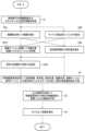
図3は、コントローラ100及びシステム10が行う処理を説明するフローチャートである。Figure 3 is a flowchart explaining the processing performed by the
まず、ステップS1において、制御部110は、内視鏡画像及びエネルギー出力設定情報を取得する。内視鏡画像は、制御部110が内視鏡システム200の本体装置220からI/Oデバイス180を介して取得できる。First, in step S1, the
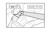
内視鏡画像は、少なくとも1つのエネルギーデバイス310及び少なくとも1つの生体組織が撮像されており、エネルギーデバイス310のエネルギーが印加される前の状態を撮像した画像であって、術野を撮像するカメラにより撮像された画像である。当該画像を処置前画像ともいう。術野を撮像するカメラとは、例えば内視鏡210であるがこれに限られない。図4に示す画像は、処置前画像の例である。図4に示す処置前画像には、エネルギーデバイス310としてバイポーラデバイスが、生体組織として動脈等が写っている。また、エネルギー出力設定情報は、制御部110がジェネレータ300からI/Oデバイス170を介して取得できる。エネルギー出力設定情報は、例えばエネルギーレベルやエネルギーシーケンス等の情報である。このようにして、ステップS1において、制御部110は、エネルギーデバイス310のエネルギー供給量に関する情報を取得する。An endoscopic image is an image of at least one
次に、制御部110はステップS2A、ステップS2Bを実行する。ステップS2Aでは、制御部110は、処置前画像に基づいて、組織検出部111で組織を検出する。Next, the
ステップS2Bでは、制御部110は、処置前画像に基づいてデバイス検出部112で、ジョウ337、338を検出する。ジョウ337、338については、後述の図6で説明する。In step S2B, the
次に、制御部110は、ステップS3A1及びステップS3A2、並びにステップS3Bを実行する。ステップS3A1では、ステップS2A及びステップA2Bの検出結果に基づいて、組織テンション評価部113で、切離対象組織にかかるテンションを評価する。切離対象組織は、医師がエネルギーデバイス310で把持し、エネルギーを出力しようとしている組織のことをいう。また、切離対象組織にかかるテンションは、エネルギーデバイス310により把持されている組織にかかる応力を指している。例えば、組織の一部がエネルギーデバイス310により把持され、引っ張られた場合、組織は伸張するように変形するが、この場合に組織にかかるテンションは高くなる。テンションのことを、張力とも記載する。ステップS3A1を実行した後、制御部110は、ステップS3A2で、ステップS3A1に基づいて、把持力評価部114で把持力を推定する。把持力はエネルギーデバイス310が先端部分の例えばジョウで切離対象組織を把持する力の強さである。また、制御部110は、ステップS3A1及びステップS3A2と並行して、ステップS3Bを実行する。Next, the
ステップS3Bでは、制御部110は把持量評価部115において、ステップS2A及びステップS2Bの検出結果に基づいて、把持量を推定する。具体的には、把持量は、後述の図8で説明するように、エネルギーデバイス310が把持している生体組織について、把持している部分の物理的な長さ、或いは面積である。In step S3B, the
次に、ステップS4で、制御部110は、熱侵襲領域予測部116で把持組織、把持量、把持位置、組織状態、組織テンション、使用デバイス又は出力設定等の情報から、エネルギーを印加した際の熱侵襲領域を予測する。熱侵襲領域とは、エネルギーデバイス310からエネルギーを供給した場合に、熱が拡散し、その熱によって生体組織に何らかの変化がもたらされるおそれのある領域のことをいう。具体的には、生体組織における蛋白質の変性、細胞内酵素の失活等の熱損傷が挙げられる。なお、以下においては、適宜、熱侵襲領域のことを熱拡散領域と記載する。把持位置は、処置対象である生体組織において、エネルギーデバイス310により把持されている部分の位置である。把持位置は、ステップS2AとステップS2Bの結果に基づいて予測することができる。組織状態は、エネルギーデバイス310による熱拡散に影響を与えうる組織の状態のことである。組織状態は、例えば、ジョウに把持された組織の周囲組織量、ジョウに把持された組織又はその周辺組織の浸漬量、又は、ジョウに把持された組織の脂肪量等である。浸漬量は、組織を覆う液体の量であり、例えば血液又はリンパ液等の体液による浸漬量である。組織状態は、例えば上記で説明したステップS2A等の結果に基づいて予測することができる。出力設定は前述したようにエネルギーレベルやエネルギーシーケンス等の設定についての情報であり、エネルギー供給量に関する情報である。制御部110は、このエネルギー供給量に関する情報は、例えばジェネレータ300から取得することができる。組織テンションは前述の処置対象組織のテンションで説明した通りであり、ステップS3A1の結果として取得することができる。把持組織はステップS2Aから、使用デバイスはステップS2Bから、把持量はステップS3Bから取得することができる。Next, in step S4, the
このようにして、制御部110は、ステップS4において、処置前画像と、エネルギー供給量に関する情報と、学習済みモデル121とに基づいて、推定熱拡散領域を推定する。推定熱拡散領域は、処置前画像上においてエネルギーデバイス310のエネルギーをエネルギー供給量に基づいて印加した後にエネルギーが到達すると推定される範囲である。In this way, in step S4, the
次に、ステップS5で、制御部110は、出力画像作成部117において熱侵襲領域の予測を内視鏡画像に重畳した出力画像を作成する。具体的には、熱侵襲領域の予測結果を内視鏡画像に例えば色を付すなどして重畳して表示を行う。Next, in step S5, the
そして最後に、ステップS6で、制御部110は、表示部230に当該画像を表示する。具体的には、制御部110は、I/Oデバイス190を介して、当該画像の含む情報を内視鏡システム200に出力し、内視鏡システム200の表示部230に当該画像が表示される。表示部230は、例えばパソコンのモニタである。このようにして、コントローラ100は、推定熱拡散領域を、カメラの撮像画像に重畳して表示部230に表示させる処理を行う。Finally, in step S6, the
3.エネルギーデバイス
以下、エネルギーデバイス310の一例として、モノポーラデバイス320、バイポーラデバイス330、超音波デバイス340及び併用デバイスについて説明する。 3. Energy Devices As examples of the
図5は、モノポーラデバイス320の構成例である。モノポーラデバイス320は、細長い円筒形状の挿入部322と、挿入部322の先端に設けられる電極321と、挿入部322の基端に接続される操作部323と、操作部323と不図示のコネクタとを接続するケーブル325とを含む。コネクタはジェネレータ300に着脱可能に接続される。5 is a configuration example of the
ジェネレータ300が出力した高周波電力はケーブル325により伝送され、電極321から出力される。患者の体外に対極板が設けられており、電極321と対極板の間で通電する。これにより、電極321が接する組織に高周波エネルギーが印加され、その組織にジュール熱が発生する。電極321は、処置の内容に応じて様々な形状の電極が採用される。モノポーラデバイス320は、通電パターンの変更により、凝固と切開の程度を調整可能である。一般に、モノポーラデバイス320の処置対象は、電極321が接する組織であるが、その電極321が接する組織の周囲に拡散した熱によって周囲組織に影響を与える可能性がある。The high-frequency power output by the
図6は、バイポーラデバイス330の構成例である。バイポーラデバイス330は、細長い円筒形状の挿入部332と、挿入部332の先端部331に設けられる2つのジョウ337、338と、挿入部332の基端に接続される操作部333と、操作部333と不図示のコネクタとを接続するケーブル335とを含む。コネクタはジェネレータ300に着脱可能に接続される。ジョウ337、338は、組織を把持すると共に把持された組織にエネルギーを印加するための可動部のことであり、基端336に設けられた軸を中心として開閉可能に構成されている。操作部333は、ジョウ337、338の開閉を操作するための把持部が設けられている。医師が把持部を握り込むことで、ジョウ337、338が閉まり組織を把持する。
6 shows a configuration example of the
ジェネレータ300が出力した高周波電力はケーブル335により伝送され、ジョウ337、338が組織を把持したとき2つのジョウ337、338の間に通電する。これにより、2つのジョウ337、338に挟まれた組織に高周波エネルギーが印加され、その組織にジュール熱が発生し、その組織が凝固する。ジェネレータ300は、ジョウ337、338に把持された組織のインピーダンス情報を計測し、そのインピーダンス情報に基づいて処置完了を検知し、エネルギー出力を自動停止してもよい。また、ジェネレータ300は、インピーダンス情報に基づいて、組織への印加エネルギーを自動調整してもよい。例えば、バイポーラデバイス330のデバイス温度は摂氏100度程度までしか上がらないが、ジョウ337、338により把持された部分の周辺に回り込み電流が生じ、その回り込み電流により熱拡散が生じる可能性がある。The high-frequency power output by the
なお、バイポーラデバイスの派生デバイスとしてベッセルシーリングデバイスがある。ベッセルシーリングデバイスは、バイポーラデバイスのジョウにカッターが設けられたデバイスであり、通電により組織を凝固した後にカッターを走らせることで組織を切離する。A derivative of the bipolar device is the vessel sealing device. The vessel sealing device is a device with a cutter attached to the jaws of the bipolar device, and after coagulating the tissue by passing an electric current through it, the tissue is separated by running the cutter over it.
図7は、超音波デバイス340の構成例である。超音波デバイス340は、細長い円筒形状の挿入部342と、挿入部342の先端部341に設けられるジョウ347及びプローブ348と、挿入部342の基端に接続される操作部343と、操作部343と不図示のコネクタとを接続するケーブル345とを含む。コネクタはジェネレータ300に着脱可能に接続される。ジョウ347は、基端346に設けられた軸を中心として可動であり、非可動のプローブ348に対して開閉可能に構成されている。操作部343は、ジョウ347の開閉を操作するための把持部が設けられている。医師が把持部を握り込むことで、ジョウ347が閉まり、ジョウ347とプローブ348が組織を把持する。操作部343には、第1出力モードが割り当てられた操作ボタン344aと、第2出力モードが割り当てられた操作ボタン344bとが設けられる。出力モードは処置内容に応じて選択されるものであり、各出力モードの操作ボタンが押されると、そのモードの出力シーケンスで超音波エネルギーが出力される。7 is a configuration example of the
ジェネレータ300が出力した電力はケーブル335により伝送され、操作ボタン344a又は344bが押されたときにプローブ348が電力を超音波に変換して出力する。これにより、ジョウ347とプローブ348に挟まれた組織に摩擦熱が発生し、その組織が凝固する又は組織が切開される。一般に、高周波デバイスの熱拡散に比べて、超音波デバイス340の熱拡散は少ないが、超音波デバイス340のデバイス温度は摂氏200度近くまで上昇する。超音波デバイス340の熱拡散は、プローブ348の先端方向に生じやすいという特性がある。The power output by the
高周波電力と超音波を併用する併用デバイスは、例えば図6の超音波デバイスと同様の構成である。但し、併用デバイスは、ジョウとプローブの間に高周波電力を通電することで、ジョウとプローブに把持された組織にジュール熱を発生させ、その組織を凝固させることができる。また併用デバイスは、超音波デバイスと同様に、プローブから超音波を出力することで、ジョウとプローブに把持された組織を切開できる。操作部に設けられた2つの操作ボタンの一方には、高周波モードが割り当てられ、他方にはシール&カットモードが割り当てられる。高周波モードは、高周波エネルギー出力のみで凝固等の処置を行うモードである。シール&カットモードは、高周波エネルギーと超音波エネルギーを併用するモードであり、高周波エネルギー出力により組織を凝固させると共に組織を切離するモードである。併用デバイスの熱拡散に関しては、例えば、バイポーラデバイスと同様な熱拡散、超音波デバイスと同様な熱拡散、又はそれら両方が生じる可能性がある。The combination device that uses high-frequency power and ultrasound is configured similarly to the ultrasound device in FIG. 6. However, the combination device can generate Joule heat in the tissue held by the jaws and the probe by passing high-frequency power between the jaws and the probe, and can coagulate the tissue. The combination device can also incise the tissue held by the jaws and the probe by outputting ultrasound from the probe, just like the ultrasound device. The high-frequency mode is assigned to one of the two operation buttons provided on the operation unit, and the seal and cut mode is assigned to the other. The high-frequency mode is a mode in which treatment such as coagulation is performed only by outputting high-frequency energy. The seal and cut mode is a mode in which high-frequency energy and ultrasound energy are used in combination, and the tissue is coagulated and cut by outputting high-frequency energy. With regard to the thermal diffusion of the combination device, for example, thermal diffusion similar to that of a bipolar device, thermal diffusion similar to that of an ultrasound device, or both may occur.
なお、以下の実施形態においては、主にバイポーラデバイス330をエネルギーデバイス310として用いる場合を例に説明する。但し、本実施形態は、熱拡散が生じる可能性がある上記の様々なエネルギーデバイスを用いる場合に適用可能である。In the following embodiment, the
4.第1実施形態
図8は、本システムの処理例の第1実施形態である。まず、制御部110は、S21A、S21Bに示す処理を実行する。具体的には、S21Aに示すインプットにおいて、制御部110は処置前画像を取得する。そして、S21Bで、制御部110はデバイスの種類を取得する。デバイスの種類は、デバイス検出部112が検出した情報から取得することができる。そして、S21Aで、制御部110は、取得した処置前画像を出力情報として、S22Aの処理を行うデバイス検出部112と、S22Bの処理を行う組織検出部111とに入力する。また、S22Bで、制御部110は、取得したデバイスの種類についての情報を出力情報として、S22Aの処理を行うデバイス検出部112に入力する。 4. First embodiment FIG. 8 shows a first embodiment of a processing example of the present system. First, the
次に、制御部110は、S22A、S22Bに示す処理を実行する。S22Aでは、エネルギーデバイス310の認識を行う。具体的には、デバイス検出部112は、機械学習によって調整された推定プログラムを実行することで、処置前画像からエネルギーデバイス310を検出する。推定プログラムは、後述の図12で説明するように、処置前画像に写った被写体からエネルギーデバイス310の種類を推定するように学習した学習済みモデル121を実行するプログラムである。S22Aでは、デバイス検出部112は、当該推定プログラムを有するネットワークに、S21Aで取得した手術中の処置前画像をインプットすることでエネルギーデバイス310を検出する。ここで、処置前画像と併せてS21Bで取得したデバイスの種類の情報又は、エネルギー供給量に関する情報をネットワークにインプットしてもよい。S22Aに示す処理で推定する対象は、エネルギーデバイス310の種類のほか、エネルギーデバイス310の存在範囲、或いはその先端部分の状態等の情報も含まれる。先端部分の状態とは、例えばジョウ337、338の開閉状態である。これらのエネルギーデバイス310に関する情報をデバイス情報という。そして、デバイス検出部112は、処置前画像上において検出したエネルギーデバイス310の領域である部分に色を付す等してラベリングをする。Next, the
S22Bでは、制御部110の組織検出部111は、制御部110の組織の認識を行う。組織検出部111は、推定プログラムを実行することで、処置前画像から生体組織を検出する。推定プログラムは、後述の図12で説明するように、処置前画像に写った被写体から生体組織の種類等を推定するように学習した学習済みモデル121を実行するプログラムである。S22Bでは、組織検出部111は、当該推定プログラムを有するネットワークに、S21Aで取得した処置前画像をインプットすることで、組織の情報を検出する。ここで、組織の情報は、処置前画像に写っている生体組織の種類、各組織の存在範囲、組織の状態等である。組織の状態には、例えばウェット、ドライの他、変色の有無等も含まれる。生体組織は、例えば、大血管、膵臓、十二指腸等の他、各組織を連結している部位、動脈、静脈等の血管等の組織も含まれる。なお、生体組織のことを単に組織とも記載する。そして、上記で検出した生体組織の種類のラベリングを行う。ラベリングは、例えば、ある生体組織の領域である部分に色を付すことにより行う。図9に示す画像は、S24AとS24Bで検出したエネルギーデバイス310と処置対象組織をラベリングした画像の例である。図9に示す画像において、エネルギーデバイス310と処置対象組織の各々について枠で囲まれるようにしてラベリングされており、文字による情報が付されている。図9の例では、処置対象組織は動脈であり、その組織の状態はドライである旨が表示されている。このようにして、組織検出部111は、処置前画像から処置前画像上に撮像される生体組織に関する情報である組織情報を抽出する。In S22B, the
そして、S22A、S22Bでラベリングのされた処置前画像が、S23の認識結果になる。制御部110は、当該認識結果をS24Aの処理を行う組織テンション評価部113、S24Bの処理を行う把持量評価部115に入力する。なお、S22Aでのデバイスの種類の入力や、S22Bでの組織の情報の入力は、医師によるマニュアル入力でもよい。また、S22Bの組織の認識においては、内視鏡画像ではなく、CT(Computed Tomography)或いはMRI(Magnetic Resonance Imaging)との3Dマッチングにより、生体組織の検出を行うこともできる。The pre-treatment images labeled in S22A and S22B become the recognition results in S23. The
次に、制御部110は、S24A、S24B及びS24Cを実行する。まず、S24Aでは、把持量評価部115は、処置対象である組織の把持量を推定する。具体的には、把持量評価部115は、推定プログラムを実行することで、S23の認識結果に基づいて処置対象である組織の把持量を推定する。推定プログラムは、エネルギーデバイス310についての情報と生体組織の情報に基づいて処置対象である組織の把持量を推定するように学習した学習済みモデル121を実行するプログラムである。当該プログラムでは、把持量を、例えばセグメンテーションした各被写体の重なりの大きさで判断する。S24Aでは、把持量評価部115は、当該推定プログラムを有するネットワークに、S23の認識結果の情報をインプットすることで、認識した画像から組織の把持量を算出する。ここで、組織の把持量は、エネルギーデバイス310が把持している生体組織について、把持している部分の物理的な長さ或いは面積である。そして、上記で検出した組織の把持量のラベリングを行う。図10に示す画像は、把持量評価部115が、S24Aで推定した組織の把持量をラベリングした画像の例である。図10に示すように、エネルギーデバイス310の先端部において、組織を把持している部分を枠で囲まれるように表示することで、組織の把持量がラベリングされる。なお、ラベリングの手法は図10に示す例に限られない。そして、把持量評価部115は、当該ラベリングのされた画像を含む情報をS26の処理を行う熱侵襲領域予測部116に入力する。Next, the
S24Bでは、組織テンション評価部113は、処置対象組織について、そのテンション状態の認識をする。具体的には、組織テンション評価部113は、推定プログラムを実行することで、S23の認識結果に基づいて処置対象組織のテンション状態を推定する。推定プログラムは、後述の図12で説明するように、S23のエネルギーデバイス310に関する情報と生体組織についての情報から、処置対象組織のテンション状態を推定するように学習した学習済みモデル121を実行するプログラムである。テンションが緩いと、なかなか組織が切れず、熱が広がっていく場合もあり、熱拡散領域の推定結果に影響を与えることがある。テンションについては、図3において説明した通りである。処置対象組織のテンションのことを、生体組織にかかる張力ともいう。In S24B, the tissue
S24Bでは、組織テンション評価部113は、当該推定プログラムを有するネットワークに、S23の認識結果の情報をインプットすることで、認識した画像から処置対象組織のテンション状態を推定する。テンション状態の推定は、例えば、学習段階で、ある組織にテンションがかかると、このように見えるということを様々なケースごとに学習しておき、実際の手術において取得した処置前画像から逆算して、今把持している組織にはどのくらいの張力がかかっているかの推定を行う。そして、組織テンション評価部113は、推定したテンション状態についての情報をS25の処理を行う把持力評価部114と、S26の処理を行う熱侵襲領域予測部116にそれぞれ入力する。In S24B, the tissue
S24Cでは、制御部110は、出力設定及び出力履歴についての情報を取得する。出力設定については、図3で説明した出力設定情報と同一である。出力履歴は、エネルギーデバイス310の出力したエネルギーレベル、出力設定設定等ついての履歴情報である。例えば、残熱量、或いはエネルギーデバイス310による処置をする前に連続して何回くらい切っているか等の情報が挙げられる。例えばエネルギーデバイス310の出力を切った直後の場合、まだ熱が残っている場合がある。従って、熱拡散する際の初期状態が異なることから、熱が拡散する領域もまた異なる。このような点から、出力履歴は熱拡散領域の推定において重要になる。これらの情報は、例えば、ジェネレータ―300から取得することができる。そして、制御部110は、取得した出力設定及び出力履歴についての情報を熱侵襲領域予測部116に入力する。In S24C, the
次に、制御部110は、S25に示す把持力の推定を行う。具体的には、把持力評価部114が、推定プログラムを実行することで、エネルギーデバイス310による組織の把持力を推定する。推定プログラムは、S24Bで推定された組織のテンション状態の情報に基づいて、組織の把持力を推定するように学習した学習済みモデル121を実行するプログラムである。S25では、把持力評価部114は、当該推定プログラムを有するネットワークに、組織のテンション状態の情報をインプットすることで把持力を推定する。把持力の推定方法は、例えば、学習段階で把持部周辺の組織について、把持する前と後での、組織の変化量、例えば大きさ、色味、反射率等と、エネルギーデバイス310により印加された把持力の関係を学習しておく。そして、実際の手術で取得した処置前画像の履歴から把持力を推定する。Next, the
把持力評価部114は、当該推定結果を含む情報をS26の処理を行う熱侵襲領域予測部116に入力する。The grip
次に、制御部110は、S26に示すように熱拡散領域の予測を行う。具体的には、制御部110の熱侵襲領域予測部116が、推定プログラムを実行することで、エネルギーデバイス310がエネルギーを出力した場合に熱拡散の範囲を推定する。推定プログラムは、処置対象の組織の種類及びテンション状態、並びにエネルギーデバイス310による組織の把持量及び把持力、並びにエネルギーデバイス310の出力設定及び出力履歴についての情報に基づいて、熱拡散範囲を推定するように学習した学習済みモデル121を実行するプログラムである。S26では、熱侵襲領域予測部116は、当該推定プログラムを有するネットワークに、当該情報をインプットすることで、認識した画像から熱拡散領域を推定する。ここで、熱拡散領域は、図3のステップS4で説明した通りである。そして、上記で検出した熱拡散領域のラベリングを行う。このようにして、制御部110は、処置前画像とエネルギー供給量に関する情報と学習済みモデル121とに基づいて、エネルギーデバイス310に処置される処置対象組織における推定熱拡散領域を推定する。図11に示す画像は、S26で推定した熱拡散領域をラベリングした画像の例である。図11に示すように、エネルギーデバイス310の先端部のジョウの周りに、熱拡散領域が枠で囲むようにして示される。例えば、画面上で熱拡散領域のラベリングは色を付すことにより表示してもよい。そして、熱侵襲領域予測部116は、当該ラベリングのされた画像を含む情報をS27の処理を行う出力画像作成部117に入力する。Next, the
最後に制御部110は、S27に示すアウトプットを行う。具体的には、制御部110の出力画像作成部117が、S26で熱侵襲領域予測部116の作成した画像を含む情報に基づいて、内視鏡システム200の表示部230に表示させる画像の作成を行う。例えば、S26での熱拡散領域のラベリングされた画像に、S22A、S22Bで認識されたエネルギーデバイス310や組織、又はS24Aで認識された把持量等の情報を重畳表示させて出力画像を作成する。このようにして、出力画像作成部117は、推定されたエネルギーデバイス310の周囲の生体組織の領域に推定熱拡散領域を重畳して表示する。ここで、推定熱拡散領域の重畳表示は、エネルギーデバイス310上に重畳表示してもよい。出力画像作成部117はこのようにして作成した出力画像を含む出力情報を、I/Oデバイス190を介して内視鏡システム200に入力する。そして、内視鏡システム200の表示部230が出力画像を表示することで、医師に熱拡散領域を提示することが可能になる。Finally, the
図12は、本システムの機械学習を行う学習装置500の構成例である。学習装置500は、処理部510と記憶部520とを含む。学習装置500は、例えばPC又はサーバ装置等の情報処理装置によって実現される。或いは、学習装置500は、ネットワークを介して接続された1又は複数の情報処理装置によって処理を実行するクラウドシステムで実現されてもよい。Figure 12 shows an example configuration of a
処理部510はCPU等のプロセッサであり、記憶部520は半導体メモリ又はハードディスクドライブ等の記憶装置である。記憶部520は、教師データ521と学習モデル522とを記憶している。ここで、教師データ521は、第1教師データ521A、第2教師データ521B、第3教師データ521C、第4教師データ521D、第5教師データ521E及び第6教師データ521Fとを含む。また、学習モデル522は、第1学習モデル522A、第2学習モデル522B、第3学習モデル522C、第4学習モデル522D、第5学習モデル522E、第6学習モデル522Fとを含む。そして、処理部510が、教師データ521を用いて学習モデル522を学習させることで、学習済みモデル121を生成する。The
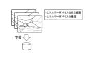
教師データ521は、エネルギー供給を受けてエネルギー出力を行う少なくとも1つのエネルギーデバイス310及び少なくとも1つの生体組織が撮像された画像である学習用デバイス組織画像又は、少なくとも1つの生体組織が撮像された画像である学習用組織画像を含む。そして、学習用デバイス組織画像と学習用組織画には、それぞれ正解データが付されている。正解データは、機械学習でのセグメンテーション(領域検出)におけるアノテーション、ディテクション(位置検出)におけるアノテーション、クラシフィケーション(分類)における正解ラベル、又はリグレッション(回帰分析)における正解ラベルである。なお、以下の説明では、学習用デバイス組織画像と学習用組織画像とを纏めて、学習用画像とも記載する。The
ここで、第1教師データ521Aはエネルギーデバイス310についての教師データ521である。また、第2教師データ521B、第3教師データ521C、第4教師データ521D、第5教師データ521E、第6教師データ521Fは、各々、生体組織、生体組織の把持量、生体組織のテンション状態、生体組織の把持力、熱拡散範囲についての教師データである。学習モデル522もこれに対応し、第1学習モデル522A、第2学習モデル522B、第3学習モデル522C、第4学習モデル522D、第5学習モデル522E、第6学習モデル522Fは、各々、エネルギーデバイス310、生体組織、生体組織の把持量、生体組織のテンション状態、生体組織の把持力、熱拡散範囲についての学習モデルある。例えば、処理部510は、エネルギーデバイス310についての第1学習モデル522Aによる推論処理に、エネルギーデバイス310についての第1教師データ521Aである学習用画像を入力する。そして、当該推論処理の結果と第1教師データ521Aとの誤差に基づいて、第1学習モデル522Aにフィードバックを行う。これを多数の第1教師データ521Aで繰り返すことで、第1学習済みモデル122を生成することができる。このようにして、様々な手術の場面において、より高い精度でエネルギーデバイス310の推定を実現することが可能になる。他の各教師データ、各学習モデル、各学習済みモデルについても同様である。そして、処理部510は、生成された学習済みモデル121を、コントローラ100に転送し、学習済みモデル121は、コントローラ100の記憶部120に記憶される。
Here, the first teacher data 521A is
図13~図17は、前述の学習段階の詳細を説明する図である。図13は、デバイス検出部112におけるエネルギーデバイス310の推定に用いられる第1学習済みモデル122についての説明図である。図13に示すように、学習装置500において、エネルギーデバイス310、生体組織の写った処置前画像に対応するアノテーションがラベリングされた第1教師データ521Aを、第1学習モデル522Aにフィードバックすることで、既存の第1学習済みモデル122を修正し、新たな第1学習済みモデル122として、コントローラ100に入力する。アノテーションの内容は、エネルギーデバイス310の種類、位置、存在範囲、或いはエネルギーデバイス310の先端部分の構成及び状態等の正解データである。Figures 13 to 17 are diagrams for explaining the details of the learning stage. Figure 13 is an explanatory diagram of the first learned model 122 used to estimate the
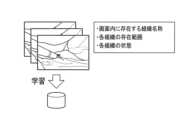
図14は、組織検出部111における生体組織の推定に用いられる第2学習済みモデル123についての説明図である。図13に示す場合と同様に、学習装置500において、処置前画像に対応するアノテーションがラベリングされた第2教師データ521Bを、第2学習モデル522Bにフィードバックすることで、既存の第2学習済みモデル123を修正し、新たな第2学習済みモデル123として、コントローラ100に入力する。アノテーションの内容は、処置前画像内に存在する組織の名称、各組織の存在範囲、各組織の状態等の正解データである。Figure 14 is an explanatory diagram of the second trained
図15は、組織テンション評価部113における処置対象組織にかかるテンションの推定に用いられる第4学習済みモデル125についての説明図である。学習装置500において、処置前画像に対応するアノテーションがラベリングされた第4教師データ521Dを、第4学習モデル522Dにフィードバックすることで、既存の第4学習済みモデル125を修正し、新たな第4学習済みモデル125として、コントローラ100に入力する。アノテーションの内容は、例えば処置対象組織の名称又はその存在する範囲、その領域のテンション印加量等の正解データである。Figure 15 is an explanatory diagram of the fourth trained
テンション印加量の第4教師データ521Dは、例えばエネルギーデバイス310の設定から取得することができる。The
図16は、把持力評価部114における把持力の推定に用いられる第5学習済みモデル126についての説明図である。学習装置500において、処置前画像に対応するアノテーションがラベリングされた第5教師データ521Eを、第5学習モデル522Eにフィードバックすることで、既存の第5学習済みモデル126を修正し、新たな第5学習済みモデル126として、コントローラ100に入力する。アノテーションの内容は、例えばテンション印加量、把持部周辺の組織変化量、把持力等の正解データである。テンション印加量の第5教師データ521Eは図15の場合と同様に、例えばエネルギーデバイス310の設定から取得することができる。把持力についてもエネルギーデバイス310の設定から取得することができる。把持部周辺の組織変化量は、例えば処置前画像の履歴情報から把持部周辺の組織の変化量を抽出することができる。FIG. 16 is an explanatory diagram of the fifth learned
図17は、熱侵襲領域予測部116における熱拡散領域の推定に用いられる第6学習済みモデル127についての説明図である。学習装置500において、処置前画像に対応するアノテーションがラベリングされた第6教師データ521Fを、第6学習モデル522Fにフィードバックすることで、既存の第6学習済みモデル127を修正し、新たな第6学習済みモデル127として、コントローラ100に入力する。アノテーションの内容は、例えば組織の種類、状態、把持量、組織テンションの印加量、把持力、出力設定、エネルギーデバイス310の種類、出力履歴、処置後の熱拡散領域等の正解データである。なお、正解データの一部については、例えば医師がラベリングしてもよい。Figure 17 is an explanatory diagram of the sixth trained
さて外科手術においてエネルギー処置を行う際のポイントとして、エネルギーデバイスからの熱拡散を抑制して周囲の臓器の熱損傷を避けることが挙げられる。しかし、処置される組織は一様ではなく、組織種類の違い、組織状態の違い又は患者の個人差等により、切離等の処置に要する時間にバラつきが生じ、熱拡散の程度も異なる。これらに対処し、熱拡散を抑制すべく、医師はエネルギーデバイスによる組織把持量や組織テンションの調整を行っているが、特に経験の浅い非エキスパートにおいては、適切な調整が困難な場合がある。よって効率的に手技を進めるためには、システムからのサポートがあることが望ましい。When performing energy treatment in surgery, it is important to suppress thermal diffusion from the energy device to avoid thermal damage to surrounding organs. However, the tissue being treated is not uniform, and differences in tissue type, tissue condition, and individual patient differences result in variations in the time required for treatment such as resection, and the degree of thermal diffusion also varies. To address these issues and suppress thermal diffusion, doctors adjust the amount of tissue gripped and the tissue tension applied by the energy device, but it can be difficult to make appropriate adjustments, especially for inexperienced non-experts. Therefore, support from the system is desirable to efficiently perform procedures.
このように、エネルギーデバイスを用いた処置においては、しばしば周囲への熱拡散に注意を要するため、医師が拡散の程度を推測しながら処置を行う。上記特許文献1では、焼灼のされた生体組織の領域と焼灼のされていない生体組織の領域をディスプレイに表示させて、次にエネルギーを出力すべき生体組織の領域を医師に提示する。しかし、エネルギー出力前とエネルギー出力開始後のCT画像の差分から温度変化を推定して出力するため、熱出力開始以降の温度変化しか推定できず、熱出力開始前に、処置具の適切な位置を提示することができない。また、どこまでが重要組織なのかということまでわからない場合がある。Thus, in treatments using energy devices, attention must often be paid to the diffusion of heat to the surroundings, and doctors perform treatments while estimating the degree of diffusion. In the above-mentioned Patent Document 1, the cauterized and non-cauterized areas of biological tissue are displayed on a display, and the area of biological tissue to which energy should next be output is shown to the doctor. However, since the temperature change is estimated and output from the difference between the CT images before and after the start of energy output, only the temperature change after the start of heat output can be estimated, and the appropriate position of the treatment tool cannot be shown before the start of heat output. Also, there are cases where it is unclear how far the critical tissue is.
この点、本システムによれば、エネルギーデバイス、生体組織等の情報に基づいて熱拡散領域の推定が行われ、推定された熱拡散領域が画面上に重畳表示される。これにより、医師は事前に熱拡散領域を知ることができるため、処置対象組織に熱損傷を与えないようなエネルギーデバイスの出力設定をすることができる。また、本システムでは、機械学習を用いた熱拡散領域の推定を行うことで、医師の経験によらず、安全かつ効率的な手術が実現でき、手術の安定性の向上が図られる。In this regard, the present system estimates the thermal diffusion area based on information on the energy device, biological tissue, etc., and the estimated thermal diffusion area is superimposed on the screen. This allows the doctor to know the thermal diffusion area in advance, and allows the output setting of the energy device to be set so as not to cause thermal damage to the tissue to be treated. In addition, the present system estimates the thermal diffusion area using machine learning, enabling safe and efficient surgery to be performed regardless of the doctor's experience, improving the stability of the surgery.
5.第2実施形態
図18は、本システムの第2実施形態におけるコントローラ100の構成例である。第2実施形態は、図2に示す第1実施形態と、把持力評価部114が異なっている。具体的には、第1実施形態では、把持力評価部114に入力される情報は、組織テンション評価部113と把持量評価部115から出力されているが、第2実施形態では、把持力評価部114に入力される情報は、コントローラ100の外部にあるジェネレータ300から出力されている。即ち、第2実施形態では、把持力評価部114は、コントローラ100の外部にあるジェネレータ300から情報を取得することで、エネルギーデバイス310の把持力を検出する。ジェネレータ300は、例えば、エネルギーデバイス310のハンドルに実装された応力センサーやポジションメータ等の把持力検出センサーから把持力の検出値を取得することができる。そして、制御部110は、処置前画像と、エネルギー供給量に関する情報と、把持力検出センサーから取得した把持力と、に基づいて、推定熱拡散領域を推定する。 5. Second embodiment FIG. 18 is a configuration example of the
図19は、本システムの第2実施形態の処理例を示している。前述した図8の第1実施形態の処理例と比較すると、S25の把持力推定が、図19ではS34Cに示す把持力計測に変わっている。そして、第2実施形態では、把持力評価部114は組織テンション評価部113の出力結果を取得しないで、例えばジェネレータ300等の外部の装置から、把持量の検出値を取得する。Figure 19 shows a processing example of the second embodiment of this system. Compared to the processing example of the first embodiment of Figure 8 described above, the grip force estimation of S25 has been changed to grip force measurement shown in S34C in Figure 19. In the second embodiment, the grip
第2実施形態によれば、エネルギーデバイス310の把持力検出センサーによって計測したデータを用いることで、把持力評価部114での推定処理をスキップすることができる。このため、熱拡散領域の推定処理の高速化が図られる。また、把持力評価部114での推定処理において、基礎とするデータの確信度が低い場合がある。このような場合に、時間をかけて推定処理を行っても、その推定結果の確信度もまた低い場合があり、このような不確かな推定結果を用いて医師が手術を行うと、効率的な手術の実現は困難になる。従って、第2実施形態によれば、より安全を保ちながら効率的な手術を実現できる。According to the second embodiment, by using data measured by the grip force detection sensor of the
6.第3実施形態
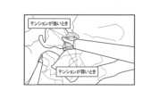
図20は、本システムの第3実施形態におけるコントローラ100の構成例である。第3実施形態は、図18に示す第2実施形態と、組織テンション評価部113が無い点が異なっている。即ち、第3実施形態では、組織テンションを機械学習によって推定しないで、熱拡散領域の推定を行う。そして、組織テンションの印加量、即ち生体組織にかかる張力によって変化する熱拡散領域を画面上に重畳表示する。例えば、テンションが強い場合の熱拡散予測範囲とテンションが弱い場合の熱拡散予測範囲の両方を提示する。また、テンションの強さについて、複数の段階の各段階に対応した推定熱拡散領域を推定してもよい。この場合、複数の段階はグラデーションであってもよい。図21は、第3実施形態を適用し、テンションが強い場合と、テンションが弱い場合のそれぞれにおける推定熱拡散領域を処置前画像に重畳表示した場合の画像の例である。組織にかかるテンションが強い場合には、エネルギーデバイス310の先端部分のジョウの両脇の狭い範囲に推定熱拡散領域が表示されている。そして、組織にかかるテンションが弱い場合には、ジョウの両脇の広い範囲に推定熱拡散領域が表示されている。 6. Third embodiment FIG. 20 is a configuration example of the
図22は、第3実施形態の処理例を示している。前述した図3の第1実施形態の処理例と比較すると、ステップS3A1の組織にかかるテンションの評価のステップがない。また、図3のS3A2に示す把持力評価部114での把持力を推定するステップもない。さらに、図22の第3実施形態では、ステップS45で熱侵襲領域の予測を組織に印加されるテンション量ごとに内視鏡画像に重畳表示をする。Figure 22 shows a processing example of the third embodiment. Compared to the processing example of the first embodiment of Figure 3 described above, there is no step of evaluating the tension applied to the tissue in step S3A1. There is also no step of estimating the gripping force in the gripping
このように第3実施形態によれば、組織テンション評価部113や把持力評価部114での推定処理をスキップできる。従って、第2実施形態の場合に比べて、さらに熱拡散領域の推定処理を高速化できる。In this way, according to the third embodiment, it is possible to skip the estimation process in the tissue
また、第3実施形態の変形例として、制御部110は、処置前画像に撮像されたエネルギーデバイス310の把持量を推定せずに、把持量の複数の段階の各段階に対応した推定熱拡散領域を推定してもよい。このようにすれば、把持量評価部115での推定処理をスキップでき、推定熱拡散領域の推定処理を高速化できる。As a modification of the third embodiment, the
7.第4実施形態
また、第1実施形態、第2実施形態のように、組織にかかるテンションとエネルギーデバイス310の把持量の測定を行った上で、推定したテンション、把持量の値の確信度が所定の値よりも低い場合に、テンション、把持量についてのベストの場合と、ワースト場合の表示を行ってもよい。また、この場合に各パラメータについて、複数の段階の各段階に対応した推定熱拡散領域を推定してもよい。即ち、第4実施形態では、例えば、組織にかかるテンションの推定における確信度が、第1所定値より低い場合、推定されたテンションを用いずに、テンションの複数の段階の各段階に対応した推定熱拡散領域を推定する。そして、把持量の推定における確信度が、第2所定値より低い場合、推定された把持力を用いずに、把持力の複数の段階の各段階に対応した熱拡散領域を推定する。第1所定値、第2所定値は、それぞれ機械学習により推定したテンションの値の確信度が低く、推定熱拡散領域の推定に用いることが適当ではないと認められる基準値であり、例えば、医師が任意に設定することができる。本実施形態によれば、医師は、表示された各段階の推定熱拡散領域の情報から、的確なエネルギー設定を選択できるようになり、安全かつ効率的に手術を行うことができる。また、第4実施形態において、テンションや把持量以外のパラメータについて、確信度が所定値よりも低い場合に、そのパラメータの推定値を推定熱拡散領域の推定に用いないようにしてもよい。なお、テンションと把持量の両方、または片方の確信度が低い場合に、第4実施形態を適用してもよい。また、第1所定値と第2所定値が同じであってもよいし、違っていてもよい。 7. Fourth embodiment As in the first and second embodiments, the tension applied to the tissue and the gripping amount of the
また、本実施形態において、制御部110は、温度又は熱ごとに推定熱拡散領域を推定し、推定した温度又は熱ごとの推定熱拡散領域を処置前画像に重畳して表示してもよい。即ち、制御部110は推定した熱拡散領域を、認識したエネルギーデバイス310や生体組織の周囲に、変数や温度、熱ごとに色分けして重畳表示することができる。In addition, in this embodiment, the
また、色に関して、例えば、テンションの表示色と、把持力の表示色の中間色で表示することもできる。例えば、図23の左側に示すように、テンションについて、テンションが強いときを赤色、テンションが弱いときを橙色というように暖色系にして、把持力について、把持力が強いときを青色、把持力が弱いときを紺色というように寒色系にしていたとする。この場合に、同図の右側に示すように、推定熱拡散領域の表示について、これらを統合して中間色で表示する。そして、テンションと把持力のパラメータについては、精度が不十分である旨の表示をすることができる。また、例えば、テンションと把持量が強い場合がベストモードになり、推定熱拡散領域が最も狭くなり、テンションと把持力が弱い場合がワーストモードになり、推定熱拡散領域が最も広くなるといった情報を表示することができる。このようにすれば、医師は、どのパラメータの確信度が低いのかを知ることができ、また、確信度の低い複数のパラメータについて、どのような組み合わせにすればベストモードにできるのかを、色に基づいて判断できるようになる。確信度の低いパラメータが複数あった場合に、医師が、各パラメータの設定をどのような組み合わせれば、熱拡散領域を最小にできるのか判断することは容易ではない。従って、このようにすれば、機械学習を用いて、各パラメータの取り得る組み合わせの中で熱拡散領域を最小にできる組み合わせを提示し、医師の判断をサポートすることができる。In addition, regarding the color, for example, it is possible to display it in an intermediate color between the display color of the tension and the display color of the gripping force. For example, as shown on the left side of FIG. 23, assume that the tension is displayed in warm colors such as red when the tension is strong and orange when the tension is weak, and the gripping force is displayed in cool colors such as blue when the gripping force is strong and navy blue when the gripping force is weak. In this case, as shown on the right side of the same figure, the estimated thermal diffusion area is displayed by integrating these. Then, it is possible to display that the accuracy of the parameters of tension and gripping force is insufficient. Also, for example, it is possible to display information such as the best mode being when the tension and gripping amount are strong, and the estimated thermal diffusion area being the narrowest, and the worst mode being when the tension and gripping force are weak, and the estimated thermal diffusion area being the widest. In this way, the doctor can know which parameters have low confidence, and can also judge based on the color what combination of multiple parameters with low confidence will result in the best mode. When there are multiple parameters with low confidence, it is not easy for a doctor to determine what combination of parameter settings can minimize the thermal diffusion region. Therefore, by using machine learning in this way, it is possible to present a combination that can minimize the thermal diffusion region from among the possible combinations of each parameter, thereby supporting the doctor's judgment.
また、図24、図25は確信度の低いパラメータが複数あった場合に、それぞれのパラメータの設定値の取り得るすべての組み合わせについて、対応する色を設定し、画面に表示させる例である。図24は、テンションと把持力について、設定値を強、または弱とした場合に、取り得るすべての組み合わせと、その組み合わせに対応する色を示している。図25は、図24に示すパラメータの組み合わせを適用した場合に、それぞれどのように推定熱拡散領域が分布するのかを、対応する色で表示した画像の例である。図25に示す場合においては、テンションと把持力のそれぞれが強となる場合に最も推定熱拡散領域は狭くなることがわかる。Figures 24 and 25 are examples in which, when there are multiple parameters with low confidence, a corresponding color is set for all possible combinations of the setting values of each parameter and displayed on the screen. Figure 24 shows all possible combinations and the colors corresponding to each combination when the setting values for tension and gripping force are set to strong or weak. Figure 25 is an example of an image that displays, in corresponding colors, how the estimated thermal diffusion area is distributed when the parameter combinations shown in Figure 24 are applied. In the case shown in Figure 25, it can be seen that the estimated thermal diffusion area is narrowest when both tension and gripping force are strong.
8.第5実施形態
図26は、本システムの第5実施形態におけるコントローラ100の構成例である。第5実施形態は、図2に示す第1実施形態と、把持力評価部114が無い点が異なっている。即ち、第5実施形態では、把持力を機械学習によって推定しないで、熱拡散領域の推定を行う。そして、把持力によって変化する熱拡散領域を画面上に重畳表示する。ここで、第5教師データ521Eには、把持力の情報をインプットしておき、様々な把持力における推定熱拡散領域を推定し、処置前画像上に重畳表示する。図27は、第5実施形態を適用し、把持力が強い場合と、把持力が弱い場合のそれぞれにおける推定熱拡散領域を処置前画像に重畳表示した場合の画像の例である。図27に示す場合においては、エネルギーデバイス310の把持力が強い場合には、エネルギーデバイス310の先端部分のジョウの両脇の狭い範囲に推定熱拡散領域が表示されている。そして、把持力が弱い場合には、ジョウの両脇の広い範囲に推定熱拡散領域が表示されている。また、この場合において、把持力の大きさについて複数の段階の各段階に対応した推定熱拡散領域を推定してもよい。 8. Fifth embodiment FIG. 26 is a configuration example of the
図28は、第5実施形態を適用した場合のコントローラ100及びシステム10が行う処理を説明するフローチャートである。図3に示したフローチャートと比較すると、図3のステップS3A2における把持力評価部114における把持力の推定を行うステップがなくなっている。また、図3のステップS5については、第5実施形態では、熱侵襲領域の予測を組織に印加される把持力ごとに内視鏡画像に重畳して出力画像を作成するようになっている。Figure 28 is a flowchart explaining the processing performed by the
第5実施形態によれば、把持力を計測せず、把持力によって変化する熱拡散領域を画面上に重畳表示することができる。従って、把持力等のセンサー等をエネルギーデバイス310等に設ける必要なくなり、低コストで本システムを実現できる。また、エネルギーデバイス310の滅菌も容易化できる。According to the fifth embodiment, the gripping force is not measured, and the thermal diffusion area that changes depending on the gripping force can be superimposed on the screen. Therefore, there is no need to provide sensors for the gripping force, etc., in the
なお、第5実施形態では、把持力の推定を行わないで推定熱拡散領域の推定を行う場合についてであるが、他のパラメータ、例えば生体組織の把持量について、同じように適用することもできる。図29は、把持量の推定を行わないで、把持量が深いときと、浅いときのそれぞれの推定熱拡散領域を異なるパターンで重畳表示した場合の画像の例である。In the fifth embodiment, the estimated thermal diffusion area is estimated without estimating the gripping force, but the same can be applied to other parameters, such as the gripping amount of biological tissue. Figure 29 shows an example of an image in which the estimated thermal diffusion areas when the gripping amount is deep and when it is shallow are superimposed in different patterns without estimating the gripping amount.
9.第6実施形態
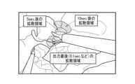
図30は、本システムの第6実施形態を適用した場合の推定熱拡散領域の表示例である。図30に示すように、エネルギー印加開始から0.1秒後、5秒後、10秒後のそれぞれにおける推定熱拡散領域が内視鏡画像に重畳して表示されている。例えば、出力直後の推定熱拡散領域が狭い領域であったとしても、処置対象組織およびその周辺組織の熱伝導や組織状態によっては、その後、短時間で推定熱拡散領域が広範囲に及ぶこともある。従って、第6実施形態によれば、エネルギーを印加し続けた際に推定熱拡散領域がどの程度まで広がるかについて知ることができ、医師はより安全かつ効率的に手術を行うことができる。 9. Sixth embodiment FIG. 30 is a display example of an estimated thermal diffusion region when the sixth embodiment of the present system is applied. As shown in FIG. 30, the estimated thermal diffusion region at 0.1 seconds, 5 seconds, and 10 seconds after the start of energy application is displayed superimposed on an endoscopic image. For example, even if the estimated thermal diffusion region immediately after output is a small region, depending on the thermal conduction and tissue state of the treatment target tissue and its surrounding tissue, the estimated thermal diffusion region may thereafter extend to a wide range in a short time. Therefore, according to the sixth embodiment, it is possible to know to what extent the estimated thermal diffusion region will expand when energy is continuously applied, and a doctor can perform surgery more safely and efficiently.
また、本実施形態のシステムは、プログラムとしても実現できる。即ち、少なくとも1つのエネルギーデバイス及び少なくとも1つの生体組織が撮像された、エネルギーデバイスのエネルギーが印加される前の状態を撮像した画像であって、術野を撮像するカメラにより撮像された処置前画像を取得し、エネルギーデバイスのエネルギー供給量に関する情報を取得する。そして、少なくとも1つのエネルギーデバイス及び少なくとも1つの生体組織が撮像された画像である学習用デバイス組織画像、又は少なくとも1つの生体組織が撮像された画像である学習用組織画像から、エネルギーデバイスからの熱が到達する範囲である熱拡散領域を出力するように学習した学習済みモデルに基づく処理により、処置前画像上においてエネルギーデバイスのエネルギーをエネルギー供給量に基づいて印加した後にエネルギーが到達すると推定される範囲である推定熱拡散領域を推定する。そして、推定熱拡散領域を、カメラの撮像画像に重畳して表示部に表示することと、をコンピュータに実行させる。ここで、コンピュータは、パソコン等のネットワーク端末等が想定される。但し、コンピュータは、スマートフォンやタブレット端末、スマートウォッチ等のウェアラブル端末であってもよい。このようにすることで、上記と同様の効果を得ることができる。The system of this embodiment can also be realized as a program. That is, a pre-treatment image is acquired by a camera that captures an operating field, which is an image of at least one energy device and at least one living tissue, before the energy of the energy device is applied, and information on the energy supply amount of the energy device is acquired. Then, from a learning device tissue image, which is an image of at least one energy device and at least one living tissue, or a learning tissue image, which is an image of at least one living tissue, an estimated heat diffusion area, which is an area where the energy is estimated to reach after the energy of the energy device is applied based on the energy supply amount, is estimated on the pre-treatment image by processing based on a trained model that has been trained to output a heat diffusion area, which is an area where the heat from the energy device reaches. Then, the computer is made to superimpose the estimated heat diffusion area on the image captured by the camera and display it on the display unit. Here, the computer is assumed to be a network terminal such as a personal computer. However, the computer may be a wearable terminal such as a smartphone, a tablet terminal, or a smart watch. By doing so, the same effect as above can be obtained.
また、本実施形態のシステムは、情報処理方法としても実現できる。即ち、情報処理方法は、少なくとも1つのエネルギーデバイス及び少なくとも1つの生体組織が撮像された、エネルギーデバイスのエネルギーが印加される前の状態を撮像した画像であって、術野を撮像するカメラにより撮像された処置前画像を取得し、エネルギーデバイスのエネルギー供給量に関する情報を取得する。そして、少なくとも1つのエネルギーデバイス及び少なくとも1つの生体組織が撮像された画像である学習用デバイス組織画像、又は少なくとも1つの生体組織が撮像された画像である学習用組織画像から、エネルギーデバイスからの熱が到達する範囲である熱拡散領域を出力するように学習した学習済みモデルに基づく処理により、処置前画像上においてエネルギーデバイスのエネルギーをエネルギー供給量に基づいて印加した後にエネルギーが到達すると推定される範囲である推定熱拡散領域を推定する。そして、推定熱拡散領域を、カメラの撮像画像に重畳して表示部に表示する。このようにすることで、上記と同様の効果を得ることができる。The system of this embodiment can also be realized as an information processing method. That is, the information processing method acquires a pre-treatment image, which is an image of at least one energy device and at least one living tissue, captured by a camera that captures an operating field, and acquires information on the energy supply amount of the energy device. Then, from a learning device tissue image, which is an image of at least one energy device and at least one living tissue, or a learning tissue image, which is an image of at least one living tissue, an estimated thermal diffusion area, which is the range where the heat from the energy device reaches, is estimated on the pre-treatment image by processing based on a trained model that has been trained to output a thermal diffusion area, which is the range where the energy is estimated to reach after the energy of the energy device is applied based on the energy supply amount. Then, the estimated thermal diffusion area is displayed on the display unit by superimposing it on the image captured by the camera. By doing so, the same effect as above can be obtained.
以上に説明した本実施形態のシステム10は、学習済みモデル121を記憶する記憶部120と、制御部110と、を含む。学習済みモデル121は、学習用デバイス組織画像又は学習用組織画像から熱拡散領域を出力するように学習される。学習用デバイス組織画像は、エネルギー供給を受けてエネルギー出力を行う少なくとも1つのエネルギーデバイス及び少なくとも1つの生体組織が撮像された画像である。学習用組織画像は、少なくとも1つの生体組織が撮像された画像である。制御部110は、少なくとも1つのエネルギーデバイス及び少なくとも1つの生体組織が撮像された、エネルギーデバイス310のエネルギーが印加される前の状態を撮像した画像であって、術野を撮像するカメラにより撮像された処置前画像を取得する。制御部110は、エネルギーデバイスのエネルギー供給量に関する情報を取得する。制御部110は、処置前画像と、エネルギー供給量に関する情報と、学習済みモデルとに基づいて、処置前画像上においてエネルギーデバイスのエネルギーをエネルギー供給量に基づいて印加した後にエネルギーが到達すると推定される範囲である推定熱拡散領域を推定する。制御部110は、推定熱拡散領域を、カメラの撮像画像に重畳して表示部に表示させる。
The
本実施形態によれば、処置前画像とエネルギー供給量に関する情報とに基づいて熱拡散領域の推定が行われ、推定された熱拡散領域が画面上に重畳表示される。これにより、医師は事前に熱拡散領域を知ることができるため、処置対象組織に熱損傷を与えないようなエネルギーデバイス310の出力設定をすることができる。また、機械学習を用いた熱拡散領域の推定を行うことで、医師の経験によらず、安全かつ効率的な手術が実現でき、手術の安定性の向上が図られる。なお、組織情報については、例えば「1.システム」で説明されている。According to this embodiment, the thermal diffusion area is estimated based on the pre-treatment image and information on the amount of energy supply, and the estimated thermal diffusion area is superimposed on the screen. This allows the doctor to know the thermal diffusion area in advance, and allows the output setting of the
また本実施形態では、制御部110は、処置前画像から、処置前画像上に撮像される生体組織に関する情報である組織情報を抽出し、組織情報とエネルギー供給量に関する情報と、に基づいて、推定熱拡散領域を推定してもよい。In addition, in this embodiment, the
本実施形態によれば、処置前画像を用いて機械学習により、処置対象組織を抽出することができる。従って、これに基づいて推定熱拡散領域の推定を行うことができる。According to this embodiment, the tissue to be treated can be extracted by machine learning using the pre-treatment image. Therefore, the estimated thermal diffusion area can be estimated based on this.
また本実施形態では、制御部110は、処置前画像から、処置前画像上に撮像されるエネルギーデバイス310に関する情報であるデバイス情報を抽出し、デバイス情報と、組織情報と、に基づいて、エネルギーデバイス310に処置される処置対象組織における推定熱拡散領域を推定してもよい。In addition, in this embodiment, the
本実施形態によれば、処置前画像を用いて機械学習により、処置対象組織とエネルギーデバイス310を抽出することができる。従って、これらの情報に基づいて推定熱拡散領域の推定を行うことができる。なお、デバイス情報については、「4.第1実施形態」で説明されている。According to this embodiment, the tissue to be treated and the
また本実施形態では、制御部110は、組織情報とデバイス情報とに基づいて、処置前画像上における処置対象組織とエネルギーデバイス310の領域を推定する。制御部110は、推定した処置対象組織とエネルギーデバイス310の領域に基づいて、処置前画像に撮像された生体組織にかかる張力、エネルギーデバイスの把持量のうちの少なくとも一つを推定結果として推定する。制御部110は、推定結果、組織情報、エネルギー供給量に関する情報に基づいて、推定熱拡散領域を推定する。Furthermore, in this embodiment, the
本実施形態によれば、生体組織にかかる張力、エネルギーデバイスの把持量についての推定結果を用いて、機械学習により推定熱拡散領域を推定することができるようになる。なお、生体組織にかかる張力については、「2.コントローラ」で、エネルギーデバイスの把持量については、「4.第1実施形態」で説明されている。According to this embodiment, it becomes possible to estimate the estimated thermal diffusion area by machine learning using the estimated results of the tension applied to the biological tissue and the gripping amount of the energy device. The tension applied to the biological tissue is explained in "2. Controller", and the gripping amount of the energy device is explained in "4. First embodiment".
また本実施形態では、制御部110は、推定した張力と処置前画像に基づいて、エネルギーデバイス310の把持力を推定し、推定した把持力に基づいて、推定熱拡散領域を推定してもよい。In addition, in this embodiment, the
本実施形態によれば、制御部110が推定した張力と処置前画像に基づき、機械学習によりエネルギーデバイス310の把持力を推定できる。従って、把持力を用いて推定熱拡散領域を推定することができる。According to this embodiment, the gripping force of the
また本実施形態では、制御部110は、エネルギーデバイス310の把持部に設けられた把持力検出センサーにより検出された把持力の検出値を取得し、取得した検出値に基づいて推定熱拡散領域を推定してもよい。In addition, in this embodiment, the
本実施形態によれば、把持力検出センサーによって計測したデータを用いることで、把持力評価部114での推定処理をスキップすることができる。このため、推定熱拡散領域の推定処理の高速化が図られる。また、推定の基礎になる把持力のデータの確信度が低い場合に、把持力検出センサーの計測したデータを用いることで、安全かつ効率的な手術を実現できる。According to this embodiment, by using data measured by the grip force detection sensor, the estimation process in the grip
また本実施形態では、制御部110は、温度又は熱ごとに推定熱拡散領域を推定し、推定した温度又は熱ごとの推定熱拡散領域を処置前画像に重畳して表示してもよい。In addition, in this embodiment, the
本実施形態によれば、制御部110は推定した熱拡散領域を、認識したエネルギーデバイス310や生体組織の周囲に、変数や温度、熱ごとに色分けして重畳して表示することができる。According to this embodiment, the
また本実施形態では、制御部110は、処置前画像から生体組織の領域とエネルギーデバイス310の領域を推定し、推定したエネルギーデバイス310の周囲の生体組織の領域に推定熱拡散領域を重畳して表示してもよい。In addition, in this embodiment, the
本実施形態によれば、処置前画像から機械学習によって、生体組織の領域とエネルギーデバイス310の領域を推定できる。従って、処置前画像に推定熱拡散領域を重畳表示することが可能になる。According to this embodiment, the area of biological tissue and the area of the
また本実施形態では、制御部110は、処置前画像に撮像された生体組織にかかる張力を推定せずに、張力の複数の段階の各段階に対応した推定熱拡散領域を推定してもよい。In addition, in this embodiment, the
本実施形態によれば、組織テンション評価部113での推定処理をスキップすることができる。従って、推定熱拡散領域の推定処理を高速化できる。なお、張力の複数の段階の各段階に対応した推定熱拡散領域の表示方法については、「6.第3実施形態」の図21で説明されている。According to this embodiment, the estimation process in the tissue
また本実施形態では、制御部110は、処置前画像に撮像されたエネルギーデバイス310の把持量を推定せずに、把持量の複数の段階の各段階に対応した推定熱拡散領域を推定してもよい。In addition, in this embodiment, the
本実施形態によれば、把持量評価部115での推定処理をスキップすることができ、推定熱拡散領域の推定処理を高速化できる。なお、把持量の複数の段階の各段階に対応した推定熱拡散領域の表示方法については、「8.第5実施形態」の図29で説明されている。According to this embodiment, the estimation process in the grip
また本実施形態では、制御部110は、制御部110は、処置前画像に基づいて、処置前画像に撮像された生体組織にかかる張力、エネルギーデバイス310の把持量を推定する。制御部110は、張力の推定における確信度が、第1所定値より低い場合、推定熱拡散領域の推定に推定された張力を用いずに、張力の複数の段階の各段階に対応した推定熱拡散領域を推定する。制御部110は、把持量の推定における確信度が、第2所定値より低い場合、推定熱拡散領域の推定に推定された把持力を用いずに、把持量の複数の段階の各段階に対応した推定熱拡散領域を推定する。
Furthermore, in this embodiment, the
本実施形態によれば、張力、把持量の推定値の確信度に応じて、熱拡散領域の推定に、当該推定値を用いるかどうかの判断をすることができるようになる。このため、推定値の確信度が低い場合には、当該推定値を用いずに、張力、把持量の複数の段階の各段階に対応した熱拡散領域を推定できるようになる。従って、医師は、表示された情報から的確なエネルギー設定を選択できるようになり、安全かつ効率的に手術を行うことができる。なお、第1所定値、第2所定値については、「7.第4実施形態」で説明されている。また、張力、把持量について複数の段階の各段階に対応した推定熱拡散領域の表示方法については、「7.第4実施形態」の図23に記載されている。According to this embodiment, it is possible to determine whether to use the estimated values for tension and grip amount in estimating the thermal diffusion area depending on the confidence level of the estimated values. Therefore, when the confidence level of the estimated value is low, it is possible to estimate the thermal diffusion area corresponding to each of the multiple stages of tension and grip amount without using the estimated value. Therefore, the doctor can select the appropriate energy setting from the displayed information, and can perform the surgery safely and efficiently. The first and second predetermined values are described in "7. Fourth embodiment". In addition, a method for displaying the estimated thermal diffusion area corresponding to each of the multiple stages of tension and grip amount is described in FIG. 23 of "7. Fourth embodiment".
また本実施形態では、制御部110は、エネルギーデバイス310が生体組織を把持する把持力の複数の段階の各段階に対応した推定熱拡散領域を推定してもよい。In addition, in this embodiment, the
本実施形態によれば、把持力を計測せず、把持力によって変化する熱拡散領域を画面上に重畳表示できる。従って、把持力等のセンサー等をエネルギーデバイス310等に設ける必要なくなり、低コストで本システムを実現できる。なお、本実施形態を用いた場合の推定熱拡散領域の表示例は図27に示されている。According to this embodiment, the thermal diffusion area that changes depending on the gripping force can be superimposed on the screen without measuring the gripping force. Therefore, there is no need to provide sensors for the gripping force, etc., in the
また本実施形態では、制御部110は、エネルギーデバイス310がエネルギーを印加する時間の複数の段階の各段階に対応した推定熱拡散領域を推定してもよい。
In this embodiment, the
本実施形態によれば、エネルギーを印加し続けた際に推定熱拡散領域がどの程度まで広がるかを知ることができ、医師は、より安全かつ効率的に手術を行うことができる。なお、時間の複数の段階の各段階に対応した推定熱拡散領域の表示方法については、「9.第6実施形態」の図30に示されている。According to this embodiment, the doctor can know the extent to which the estimated thermal diffusion area will expand when energy is continuously applied, and can perform surgery more safely and efficiently. Note that a method for displaying the estimated thermal diffusion area corresponding to each of multiple time stages is shown in Figure 30 of "9. Sixth embodiment".
また、以上の処理はプログラムとして記述されてもよい。即ち、本実施形態のプログラムは、処置前画像を取得することと、エネルギー供給量に関する情報を取得することと、学習済みモデル121に基づく処理により、エネルギーが到達すると推定される推定熱拡散領域を推定することと、推定熱拡散領域を、カメラの撮像画像に重畳して表示部に表示することと、をコントローラ100に実行させる。The above processing may be written as a program. That is, the program of this embodiment causes the
また、以上の処理は情報処理方法として記述されてもよい。即ち、本実施形態の情報処理方法は、処置前画像を取得し、エネルギー供給量に関する情報を取得し、学習済みモデル121に基づく処理により、エネルギーが到達すると推定される推定熱拡散領域を推定し、推定熱拡散領域をカメラの撮像画像に重畳して表示部に表示する。The above processing may be described as an information processing method. That is, the information processing method of this embodiment acquires a pre-treatment image, acquires information regarding the amount of energy supply, estimates an estimated thermal diffusion area where the energy is estimated to reach by processing based on the trained
以上、本実施形態およびその変形例について説明したが、本開示は、各実施形態やその変形例そのままに限定されるものではなく、実施段階では、要旨を逸脱しない範囲内で構成要素を変形して具体化することができる。また、上記した各実施形態や変形例に開示されている複数の構成要素を適宜組み合わせることができる。例えば、各実施形態や変形例に記載した全構成要素からいくつかの構成要素を削除してもよい。さらに、異なる実施の形態や変形例で説明した構成要素を適宜組み合わせてもよい。このように、本開示の主旨を逸脱しない範囲内において種々の変形や応用が可能である。また、明細書又は図面において、少なくとも一度、より広義または同義な異なる用語と共に記載された用語は、明細書又は図面のいかなる箇所においても、その異なる用語に置き換えることができる。Although the present embodiment and its modified examples have been described above, the present disclosure is not limited to each embodiment or its modified example as it is, and in the implementation stage, the components can be modified and embodied within the scope of the gist. In addition, multiple components disclosed in each of the above-mentioned embodiments and modified examples can be appropriately combined. For example, some components may be deleted from all the components described in each embodiment or modified example. Furthermore, components described in different embodiments or modified examples may be appropriately combined. In this way, various modifications and applications are possible within the scope of the gist of the present disclosure. In addition, a term described at least once in the specification or drawings together with a different term having a broader meaning or the same meaning can be replaced with that different term anywhere in the specification or drawings.
10 システム、100 コントローラ、110 制御部、111 組織検出部、112 デバイス検出部、113 組織テンション評価部、114 把持力評価部、115 把持量評価部、116 熱侵襲領域予測部、117 出力画像作成部、118 把持力評価部、120 記憶部、121 学習済みモデル、122 第1学習済みモデル、123 第2学習済みモデル、124 第3学習済みモデル、125 第4学習済みモデル、126 第5学習済みモデル、127 第6学習済みモデル、170 I/Oデバイス、180 I/Oデバイス、190 I/Oデバイス、200 内視鏡システム、210 内視鏡、220 本体装置、230 ディスプレイ、230 表示部、300 ジェネレータ、310 エネルギーデバイス、320 モノポーラデバイス、321 電極、322 挿入部、323 操作部、325 ケーブル、330 バイポーラデバイス、331 先端部、332 挿入部、333 操作部、335 ケーブル、336 基端、337 ジョウ、338 ジョウ、340 超音波デバイス、341 先端部、342 挿入部、343 操作部、344a 操作ボタン、344b 操作ボタン、345 ケーブル、346 基端、347 ジョウ、348 プローブ、500 学習装置、510 処理部、520 記憶部、521 教師データ、521A 第1教師データ、521B 第2教師データ、521C 第3教師データ、521D 第4教師データ、521E 第5教師データ、521F 第6教師データ、522 学習モデル、522A 第1学習モデル、522B 第2学習モデル、522C 第3学習モデル、522D 第4学習モデル、522E 第5学習モデル、522F 第6学習モデル、S1 ステップ、S2A ステップ、S2B ステップ、S3A1 ステップ、S3A2 ステップ、S3B ステップ、S4 ステップ、S41 ステップ、S42A ステップ、S42B ステップ、S43 ステップ、S44 ステップ、S45 ステップ、S46 ステップ、S5 ステップ、S51 ステップ、S52A ステップ、S52B ステップ、S53A ステップ、S53B ステップ、S54 ステップ、S55 ステップ、S56 ステップ、S6 ステップ10 System, 100 Controller, 110 Control unit, 111 Tissue detection unit, 112 Device detection unit, 113 Tissue tension evaluation unit, 114 Grasping force evaluation unit, 115 Grasping amount evaluation unit, 116 Thermal invasion area prediction unit, 117 Output image creation unit, 118 Grasping force evaluation unit, 120 Memory unit, 121 Trained model, 122 First trained model, 123 Second trained model, 124 Third trained model, 125 Fourth trained model, 126 Fifth trained model, 127 Sixth trained model, 170 I/O device, 180 I/O device, 190 I/O device, 200 Endoscope system, 210 Endoscope, 220 Main body device, 230 Display, 230 Display unit, 300 Generator, 310 Energy device, 320 Monopolar device, 321 Electrode, 322 Insertion section, 323 Operation section, 325 Cable, 330 Bipolar device, 331 Tip section, 332 Insertion section, 333 Operation section, 335 Cable, 336 Base end, 337 Jaw, 338 Jaw, 340 Ultrasonic device, 341 Tip section, 342 Insertion section, 343 Operation section, 344a Operation button, 344b Operation button, 345 Cable, 346 Base end, 347 Jaw, 348 Probe, 500 Learning device, 510 Processing section, 520 Memory section, 521 Teacher data, 521A First teacher data, 521B Second teacher data, 521C Third teacher data, 521D Fourth teacher data, 521E Fifth teacher data, 521F Sixth teacher data, 522 Learning model, 522A First learning model, 522B Second learning model, 522C third learning model, 522D fourth learning model, 522E fifth learning model, 522F sixth learning model, S1 step, S2A step, S2B step, S3A1 step, S3A2 step, S3B step, S4 step, S41 step, S42A step, S42B step, S43 step, S44 step, S45 step, S46 step, S5 step, S51 step, S52A step, S52B step, S53A step, S53B step, S54 step, S55 step, S56 step, S6 step
Claims (19)
Translated fromJapanese制御部と、
を含み、
前記制御部は、
前記少なくとも1つのエネルギーデバイス及び前記少なくとも1つの生体組織が撮像された、前記エネルギーデバイスのエネルギーが印加される前の状態を撮像した画像であって、術野を撮像するカメラにより撮像された処置前画像を取得し、
前記エネルギーデバイスのエネルギー供給量に関する情報を取得し、
前記処置前画像と、前記エネルギー供給量に関する情報と、前記学習済みモデルとに基づいて、前記処置前画像上において前記エネルギーデバイスのエネルギーを前記エネルギー供給量に基づいて印加した後に前記エネルギーが到達すると推定される範囲である推定熱拡散領域を推定し、
前記推定熱拡散領域を、前記カメラの撮像画像に重畳して表示部に表示させる処理を行うことを特徴とするシステム。 a memory unit that stores a trained model that has been trained to output a thermal diffusion region, which is a range reached by heat from the energy device, from a learning device tissue image, which is an image of at least one energy device that receives energy supply and outputs energy and at least one biological tissue, or a learning tissue image, which is an image of the at least one biological tissue;
A control unit;
Including,
The control unit is
obtaining a pre-treatment image of the at least one energy device and the at least one biological tissue before energy is applied to the energy device, the pre-treatment image being captured by a camera that captures an image of a surgical field;
Obtaining information regarding the energy supply amount of the energy device;
Based on the pre-treatment image, the information on the energy supply amount, and the trained model, an estimated thermal diffusion area is estimated to be a range where the energy is estimated to reach after the energy of the energy device is applied on the pre-treatment image based on the energy supply amount;
The system is characterized by performing processing for superimposing the estimated thermal diffusion region on an image captured by the camera and displaying it on a display unit.
前記制御部は、前記処置前画像から、前記処置前画像上に撮像される生体組織に関する情報である組織情報を抽出し、
前記組織情報と前記エネルギー供給量に関する情報と、に基づいて、前記推定熱拡散領域を推定することを特徴とするシステム。 2. The system of claim 1,
The control unit extracts tissue information from the pretreatment image, the tissue information being information about a biological tissue imaged on the pretreatment image;
A system for estimating the estimated thermal diffusion area based on the tissue information and information related to the amount of energy supply.
前記制御部は、前記処置前画像から、前記処置前画像上に撮像される前記エネルギーデバイスに関する情報であるデバイス情報を抽出し、
前記デバイス情報と、前記組織情報と、に基づいて、前記エネルギーデバイスに処置される処置対象組織における前記推定熱拡散領域を推定することを特徴とするシステム。 3. The system according to claim 2,
The control unit extracts device information from the pre-treatment image, the device information being information about the energy device imaged on the pre-treatment image,
A system comprising: a device information unit that estimates an estimated thermal diffusion area in a target tissue treated by the energy device based on the device information and the tissue information.
前記制御部は、前記組織情報と前記デバイス情報とに基づいて、前記処置前画像上における前記処置対象組織と前記エネルギーデバイスの領域を推定し、
推定した前記処置対象組織とエネルギーデバイスの領域に基づいて、前記処置前画像に撮像された生体組織にかかる張力、前記エネルギーデバイスの把持量のうちの少なくとも一つを推定結果として推定し、
前記推定結果、前記組織情報、前記エネルギー供給量に関する情報に基づいて、前記推定熱拡散領域を推定することを特徴とするシステム。 4. The system according to claim 3,
The control unit estimates regions of the treatment target tissue and the energy device on the pre-treatment image based on the tissue information and the device information,
Based on the estimated areas of the treatment target tissue and the energy device, at least one of the tension applied to the biological tissue captured in the pre-treatment image and the gripping amount of the energy device is estimated as an estimated result;
A system for estimating the estimated thermal diffusion area based on the estimation result, the tissue information, and information regarding the amount of energy supply.
前記制御部は、前記推定した張力と前記処置前画像に基づいて、エネルギーデバイスの把持力を推定し、推定した把持力に基づいて、前記推定熱拡散領域を推定することを特徴とするシステム。 5. The system according to claim 4,
The system is characterized in that the control unit estimates a gripping force of an energy device based on the estimated tension and the pre-treatment image, and estimates the estimated thermal diffusion area based on the estimated gripping force.
前記制御部は、前記エネルギーデバイスの把持部に設けられた把持力検出センサーにより検出された把持力の検出値を取得し、取得した前記検出値に基づいて前記推定熱拡散領域を推定することを特徴とするシステム。 2. The system of claim 1,
The control unit acquires a detection value of a gripping force detected by a gripping force detection sensor provided in a gripping portion of the energy device, and estimates the estimated thermal diffusion area based on the acquired detection value.
前記制御部は、温度又は熱ごとに前記推定熱拡散領域を推定し、推定した前記温度又は前記熱ごとの前記推定熱拡散領域を前記処置前画像に重畳して表示することを特徴とするシステム。 2. The system of claim 1,
The system is characterized in that the control unit estimates the estimated thermal diffusion area for each temperature or heat, and displays the estimated thermal diffusion area for each estimated temperature or heat superimposed on the pre-treatment image.
前記制御部は前記処置前画像から生体組織の領域とエネルギーデバイスの領域を推定し、推定した前記エネルギーデバイスの周囲の生体組織の領域に前記推定熱拡散領域を重畳して表示することを特徴とするシステム。 6. The system according to claim 5,
The system is characterized in that the control unit estimates the area of biological tissue and the area of the energy device from the pre-treatment image, and displays the estimated thermal diffusion area superimposed on the estimated area of biological tissue surrounding the energy device.
前記制御部は、前記処置前画像に撮像された生体組織にかかる張力を推定せずに、前記張力の複数の段階の各段階に対応した前記推定熱拡散領域を推定することを特徴とするシステム。 2. The system of claim 1,
The system is characterized in that the control unit estimates the estimated thermal diffusion area corresponding to each of multiple stages of tension without estimating the tension applied to the biological tissue imaged in the pre-treatment image.
前記制御部は、前記処置前画像に撮像されたエネルギーデバイスの把持量を推定せずに、前記把持量の複数の段階の各段階に対応した前記推定熱拡散領域を推定することを特徴とするシステム。 2. The system of claim 1,
The system is characterized in that the control unit estimates the estimated thermal diffusion area corresponding to each of multiple stages of the grasping amount without estimating the grasping amount of the energy device captured in the pre-treatment image.
前記制御部は、前記処置前画像に基づいて、前記処置前画像に撮像された生体組織にかかる張力、前記エネルギーデバイスの把持量を推定し、
前記張力の推定における確信度が、第1所定値より低い場合、前記推定熱拡散領域の推定に前記推定された張力を用いずに、前記張力の複数の段階の各段階に対応した前記推定熱拡散領域を推定し、
前記把持量の推定における確信度が、第2所定値より低い場合、前記推定熱拡散領域の推定に前記推定された把持量を用いずに、前記把持量の複数の段階の各段階に対応した前記推定熱拡散領域を推定することを特徴とするシステム。
2. The system of claim 1,
The control unit estimates a tension applied to the biological tissue captured in the pre-treatment image and a gripping amount of the energy device based on the pre-treatment image,
If the degree of certainty in the estimation of the tension is lower than a first predetermined value, the estimated tension is not used in estimating the estimated thermal diffusion region, and the estimated thermal diffusion region corresponding to each of the multiple stages of the tension is estimated;
A system characterized by estimating the estimated thermal diffusion area corresponding to each of multiple stages of the gripping amount without using the estimated gripping amount to estimate theestimated thermal diffusion area when the confidence in the estimation of the gripping amount is lower than a second predetermined value.
前記制御部は、前記エネルギーデバイスが生体組織を把持する把持力の複数の段階の各段階に対応した前記推定熱拡散領域を推定することを特徴とするシステム。 2. The system of claim 1,
The control unit estimates the estimated thermal diffusion area corresponding to each of a plurality of stages of gripping force with which the energy device grips biological tissue.
前記制御部は、前記エネルギーデバイスがエネルギーを印加する時間の複数の段階の各段階に対応した前記推定熱拡散領域を推定することを特徴とするシステム。
2. The system of claim 1,
The system is characterized in that the control unit estimates the estimated thermal diffusion area corresponding to each of multiple stages of time during which the energy deviceapplies energy .
前記少なくとも1つのエネルギーデバイス及び前記少なくとも1つの生体組織が撮像された画像である学習用デバイス組織画像、又は前記少なくとも1つの生体組織が撮像された画像である学習用組織画像から、前記エネルギーデバイスからの熱が到達する範囲である熱拡散領域を出力するように学習した学習済みモデルに基づく処理により、前記処置前画像上において前記エネルギーデバイスのエネルギーを前記エネルギー供給量に基づいて印加した後に前記エネルギーが到達すると推定される範囲である推定熱拡散領域を推定することと、
前記推定熱拡散領域を、前記カメラの撮像画像に重畳して表示部に表示することと、をコンピュータに実行させることを特徴とするプログラム。
acquiring a pre-treatment image of at least one energy device and at least one biological tissue captured by a camera that captures an image of a surgical field before energy is applied from the energy device, and acquiring information regarding an amount of energy supplied from the energy device;
estimating an estimated thermal diffusion area, which is the area where the energy is estimated to reach after applying energy from the energy device based on the energy supply amount on the pre-treatment image, by processing based on a trained model that has been trained to output a thermal diffusion area, which is the area where the heat from the energy device reaches, from a training device tissue image, which is an image of the at least one energy device and the at least one biological tissue, or a training tissue image, which is an image of the at least one biological tissue;
and displaying the estimated thermal diffusion region ona display unit so as to be superimposed on an image captured by the camera.
前記処置前画像から、前記処置前画像上に撮像される生体組織に関する情報である組織情報を抽出することと、
前記処置前画像から、前記処置前画像上に撮像される前記エネルギーデバイスに関する情報であるデバイス情報を抽出することと、
前記デバイス情報と、前記組織情報と、に基づいて、前記エネルギーデバイスに処置される処置対象組織における前記推定熱拡散領域を推定することを特徴とするプログラム。 The program according to claim 14,
extracting tissue information from the pretreatment image, the tissue information being information about a biological tissue imaged on the pretreatment image;
extracting device information from the pre-treatment image, the device information being information about the energy device imaged on the pre-treatment image;
A program for estimating the estimated thermal diffusion area in a target tissue to be treated by the energy device based on the device information and the tissue information.
前記組織情報と前記デバイス情報とに基づいて、前記処置前画像上における前記処置対象組織と前記エネルギーデバイスの領域を推定することと、
推定した前記処置対象組織とエネルギーデバイスの領域に基づいて、前記処置前画像に撮像された生体組織にかかる張力、前記エネルギーデバイスの把持量のうちの少なくとも一つを推定結果として推定することと、
前記推定結果、前記組織情報、前記エネルギー供給量に関する情報に基づいて、前記推定熱拡散領域を推定することを特徴とするプログラム。 The program according to claim 15,
Estimating regions of the treatment target tissue and the energy device on the pre-treatment image based on the tissue information and the device information;
Based on the estimated areas of the treatment target tissue and the energy device, estimating at least one of a tension applied to the biological tissue captured in the pre-treatment image and a gripping amount of the energy device as an estimation result;
A program for estimating the estimated thermal diffusion region based on the estimation result, the tissue information, and information regarding the amount of energy supply.
前記少なくとも1つのエネルギーデバイス及び前記少なくとも1つの生体組織が撮像された画像である学習用デバイス組織画像、又は前記少なくとも1つの生体組織が撮像された画像である学習用組織画像から、前記エネルギーデバイスからの熱が到達する範囲である熱拡散領域を出力するように学習した学習済みモデルに基づく処理により、前記処置前画像上において前記エネルギーデバイスのエネルギーを前記エネルギー供給量に基づいて印加した後に前記エネルギーが到達すると推定される範囲である推定熱拡散領域を推定することと、
前記推定熱拡散領域を、前記カメラの撮像画像に重畳して表示部に表示することと、を特徴とする情報処理方法。
acquiring a pre-treatment image of at least one energy device and at least one biological tissue captured by a camera that captures an image of a surgical field before energy is applied from the energy device, and acquiring information regarding an amount of energy supplied from the energy device;
estimating an estimated thermal diffusion area, which is the area where the energy is estimated to reach after applying energy from the energy device based on the energy supply amount on the pre-treatment image, by processing based on a trained model that has been trained to output a thermal diffusion area, which is the area where the heat from the energy device reaches, from a training device tissue image, which is an image of the at least one energy device and the at least one biological tissue, or a training tissue image, which is an image of the at least one biological tissue;
and displaying the estimated thermal diffusion region ona display unit so as to be superimposed on an image captured by the camera.
前記処置前画像から、前記処置前画像上に撮像される生体組織に関する情報である組織情報を抽出することと、
前記処置前画像から、前記処置前画像上に撮像される前記エネルギーデバイスに関する情報であるデバイス情報を抽出することと、
前記デバイス情報と、前記組織情報と、に基づいて、前記エネルギーデバイスに処置される処置対象組織における前記推定熱拡散領域を推定することを特徴とする情報処理方法。 18. The information processing method according to claim 17,
extracting tissue information from the pretreatment image, the tissue information being information about a biological tissue imaged on the pretreatment image;
extracting device information from the pre-treatment image, the device information being information about the energy device imaged on the pre-treatment image;
An information processing method comprising: estimating the estimated thermal diffusion area in a target tissue to be treated by the energy device based on the device information and the tissue information.
前記組織情報と前記デバイス情報とに基づいて、前記処置前画像上における前記処置対象組織と前記エネルギーデバイスの領域を推定することと、
推定した前記処置対象組織とエネルギーデバイスの領域に基づいて、前記処置前画像に撮像された生体組織にかかる張力、前記エネルギーデバイスの把持量のうちの少なくとも一つを推定結果として推定することと、
前記推定結果、前記組織情報、前記エネルギー供給量に関する情報に基づいて、前記推定熱拡散領域を推定することを特徴とする情報処理方法。 20. The information processing method according to claim 18,
Estimating regions of the treatment target tissue and the energy device on the pre-treatment image based on the tissue information and the device information;
Based on the estimated areas of the treatment target tissue and the energy device, estimating at least one of a tension applied to the biological tissue captured in the pre-treatment image and a gripping amount of the energy device as an estimation result;
An information processing method comprising: estimating the estimated thermal diffusion region based on the estimation result, the tissue information, and information regarding the amount of energy supply.
Applications Claiming Priority (5)
| Application Number | Priority Date | Filing Date | Title |
|---|---|---|---|
| US202163221128P | 2021-07-13 | 2021-07-13 | |
| US63/221,128 | 2021-07-13 | ||
| US202163222252P | 2021-07-15 | 2021-07-15 | |
| US63/222,252 | 2021-07-15 | ||
| PCT/JP2022/009692WO2023286335A1 (en) | 2021-07-13 | 2022-03-07 | System, program, and information processing method |
Publications (3)
| Publication Number | Publication Date |
|---|---|
| JPWO2023286335A1 JPWO2023286335A1 (en) | 2023-01-19 |
| JPWO2023286335A5 JPWO2023286335A5 (en) | 2023-11-20 |
| JP7465413B2true JP7465413B2 (en) | 2024-04-10 |
Family
ID=84919163
Family Applications (4)
| Application Number | Title | Priority Date | Filing Date |
|---|---|---|---|
| JP2023535109AActiveJP7493684B2 (en) | 2021-07-13 | 2022-03-07 | System and Program |
| JP2023535110AActiveJP7465413B2 (en) | 2021-07-13 | 2022-03-07 | System, program and information processing method |
| JP2023535112AActiveJP7602646B2 (en) | 2021-07-13 | 2022-03-07 | System, program and information processing method |
| JP2023535111AActiveJP7602645B2 (en) | 2021-07-13 | 2022-03-07 | system |
Family Applications Before (1)
| Application Number | Title | Priority Date | Filing Date |
|---|---|---|---|
| JP2023535109AActiveJP7493684B2 (en) | 2021-07-13 | 2022-03-07 | System and Program |
Family Applications After (2)
| Application Number | Title | Priority Date | Filing Date |
|---|---|---|---|
| JP2023535112AActiveJP7602646B2 (en) | 2021-07-13 | 2022-03-07 | System, program and information processing method |
| JP2023535111AActiveJP7602645B2 (en) | 2021-07-13 | 2022-03-07 | system |
Country Status (3)
| Country | Link |
|---|---|
| US (4) | US20230380695A1 (en) |
| JP (4) | JP7493684B2 (en) |
| WO (4) | WO2023286336A1 (en) |
Families Citing this family (4)
| Publication number | Priority date | Publication date | Assignee | Title |
|---|---|---|---|---|
| JP2025058623A (en)* | 2023-09-28 | 2025-04-09 | オムロン株式会社 | Model generation method and inference program |
| WO2025115599A1 (en) | 2023-11-28 | 2025-06-05 | オリンパスメディカルシステムズ株式会社 | Assistance device, assistance method, and recording medium |
| EP4574007A1 (en)* | 2023-12-22 | 2025-06-25 | Olympus Winter & Ibe GmbH | Medical camera system and method for capturing images and processing said images |
| CN118680657B (en)* | 2024-06-05 | 2025-06-13 | 河北壹雪制冷科技有限公司 | A freezing pen control device based on sensor feedback |
Citations (2)
| Publication number | Priority date | Publication date | Assignee | Title |
|---|---|---|---|---|
| JP2018511403A (en) | 2015-04-02 | 2018-04-26 | ハートフロー, インコーポレイテッド | System and method for providing personalized estimation of bioheat transfer |
| JP2019170809A (en) | 2018-03-29 | 2019-10-10 | 株式会社日立製作所 | Medical system |
Family Cites Families (14)
| Publication number | Priority date | Publication date | Assignee | Title |
|---|---|---|---|---|
| US9259287B2 (en) | 2013-04-02 | 2016-02-16 | Siemens Aktiengesellschaft | Patient specific planning and simulation of ablative procedures |
| WO2017090165A1 (en)* | 2015-11-26 | 2017-06-01 | オリンパス株式会社 | Treatment system and treatment instrument |
| US10786298B2 (en) | 2016-03-01 | 2020-09-29 | Covidien Lp | Surgical instruments and systems incorporating machine learning based tissue identification and methods thereof |
| US11908584B2 (en)* | 2017-05-15 | 2024-02-20 | Ne Scientific, Llc | Methods and systems for modeling a necrotized tissue volume in an ablation procedure |
| CN119184842A (en)* | 2018-02-23 | 2024-12-27 | 生物相容英国有限公司 | Volumetric imaging |
| US11510720B2 (en)* | 2018-09-07 | 2022-11-29 | Cilag Gmbh International | Managing simultaneous monopolar outputs using duty cycle and synchronization |
| WO2020095389A1 (en)* | 2018-11-07 | 2020-05-14 | オリンパス株式会社 | Medical device, residual-heat determination method, and residual-heat determination program |
| CN113164196A (en)* | 2018-11-20 | 2021-07-23 | 皇家飞利浦有限公司 | Temporal mapping of thermal ablation zones |
| US20210038314A1 (en)* | 2019-08-11 | 2021-02-11 | phenoMapper, LLC | Method and System for Personalized Treatment Planning in Ablation of Cancerous Tissue |
| JP2021029258A (en)* | 2019-08-13 | 2021-03-01 | ソニー株式会社 | Surgery support system, surgery support method, information processing device, and information processing program |
| JP2021029979A (en)* | 2019-08-29 | 2021-03-01 | 国立研究開発法人国立がん研究センター | Teaching data generation device, teaching data generation program, and teaching data generation method |
| US20210085387A1 (en)* | 2019-09-22 | 2021-03-25 | Biosense Webster (Israel) Ltd. | Guiding cardiac ablation using machine learning (ml) |
| JP7438731B2 (en)* | 2019-11-29 | 2024-02-27 | キヤノンメディカルシステムズ株式会社 | Medical image processing device, operating method of the medical image processing device, and medical image processing program |
| JP7482690B2 (en)* | 2020-06-04 | 2024-05-14 | リンナイ株式会社 | Cooking system, cooking method, learning device and learning method |
- 2022
- 2022-03-07JPJP2023535109Apatent/JP7493684B2/enactiveActive
- 2022-03-07JPJP2023535110Apatent/JP7465413B2/enactiveActive
- 2022-03-07WOPCT/JP2022/009693patent/WO2023286336A1/ennot_activeCeased
- 2022-03-07JPJP2023535112Apatent/JP7602646B2/enactiveActive
- 2022-03-07WOPCT/JP2022/009691patent/WO2023286334A1/ennot_activeCeased
- 2022-03-07WOPCT/JP2022/009694patent/WO2023286337A1/ennot_activeCeased
- 2022-03-07JPJP2023535111Apatent/JP7602645B2/enactiveActive
- 2022-03-07WOPCT/JP2022/009692patent/WO2023286335A1/ennot_activeCeased
- 2023
- 2023-08-15USUS18/234,168patent/US20230380695A1/enactivePending
- 2023-08-24USUS18/237,599patent/US20230404652A1/enactivePending
- 2023-08-24USUS18/237,732patent/US20230410298A1/enactivePending
- 2023-09-14USUS18/368,100patent/US20230419486A1/enactivePending
Patent Citations (2)
| Publication number | Priority date | Publication date | Assignee | Title |
|---|---|---|---|---|
| JP2018511403A (en) | 2015-04-02 | 2018-04-26 | ハートフロー, インコーポレイテッド | System and method for providing personalized estimation of bioheat transfer |
| JP2019170809A (en) | 2018-03-29 | 2019-10-10 | 株式会社日立製作所 | Medical system |
Also Published As
| Publication number | Publication date |
|---|---|
| US20230404652A1 (en) | 2023-12-21 |
| JP7602645B2 (en) | 2024-12-18 |
| US20230419486A1 (en) | 2023-12-28 |
| JPWO2023286334A1 (en) | 2023-01-19 |
| JPWO2023286335A1 (en) | 2023-01-19 |
| JP7602646B2 (en) | 2024-12-18 |
| US20230410298A1 (en) | 2023-12-21 |
| US20230380695A1 (en) | 2023-11-30 |
| JPWO2023286336A1 (en) | 2023-01-19 |
| JPWO2023286337A1 (en) | 2023-01-19 |
| WO2023286335A1 (en) | 2023-01-19 |
| WO2023286336A1 (en) | 2023-01-19 |
| WO2023286337A1 (en) | 2023-01-19 |
| JP7493684B2 (en) | 2024-05-31 |
| WO2023286334A1 (en) | 2023-01-19 |
Similar Documents
| Publication | Publication Date | Title |
|---|---|---|
| JP7465413B2 (en) | System, program and information processing method | |
| CN112804958B (en) | Indicator system | |
| EP4285853A1 (en) | Surgery details evaluation system, surgery details evaluation method, and computer program | |
| EP4301264B1 (en) | Tissue therapy energy delivery using optical imaging | |
| WO2023095492A1 (en) | Surgery assisting system, surgery assisting method, and surgery assisting program | |
| US20210100606A1 (en) | Systems and methods for controlling delivery of electrosurgical energy | |
| JPWO2023286334A5 (en) | ||
| US20230071343A1 (en) | Energy-based surgical systems and methods based on an artificial-intelligence learning system | |
| JP7483360B2 (en) | Semi-automated ablation system | |
| US20240260811A1 (en) | Medical system and notification method | |
| WO2017187523A1 (en) | Energy treatment tool, treatment system, and control device | |
| US20230240512A1 (en) | Endoscope system, manipulation assistance method, and manipulation assistance program | |
| US20230042032A1 (en) | Energy-based surgical systems and methods based on an artificial-intelligence learning system | |
| CN116416487A (en) | Training data generation method, control device and control method, energy processing device | |
| CN116887771A (en) | System, program, and energy output adjustment method | |
| CN117460474A (en) | Tissue treatment energy delivery using optical imaging | |
| US20250204763A1 (en) | Medical camera system and method for capturing images and processing said images | |
| JP7148193B1 (en) | Surgery support system, surgery support method, and surgery support program | |
| US20240335093A1 (en) | Medical support device, endoscope system, medical support method, and program | |
| WO2025136834A1 (en) | Tissue therapy energy feedback systems and methods | |
| WO2024195020A1 (en) | Endoscope examination assistance device, endoscope examination assistance method, and recording medium | |
| JP2024067489A (en) | Medical support device, endoscope, medical support method, and program |
Legal Events
| Date | Code | Title | Description |
|---|---|---|---|
| A521 | Request for written amendment filed | Free format text:JAPANESE INTERMEDIATE CODE: A523 Effective date:20230824 | |
| A621 | Written request for application examination | Free format text:JAPANESE INTERMEDIATE CODE: A621 Effective date:20230824 | |
| TRDD | Decision of grant or rejection written | ||
| A01 | Written decision to grant a patent or to grant a registration (utility model) | Free format text:JAPANESE INTERMEDIATE CODE: A01 Effective date:20240305 | |
| A61 | First payment of annual fees (during grant procedure) | Free format text:JAPANESE INTERMEDIATE CODE: A61 Effective date:20240329 | |
| R150 | Certificate of patent or registration of utility model | Ref document number:7465413 Country of ref document:JP Free format text:JAPANESE INTERMEDIATE CODE: R150 |