JP7465254B2 - Fluid injection device - Google Patents
Fluid injection deviceDownload PDFInfo
- Publication number
- JP7465254B2 JP7465254B2JP2021500914AJP2021500914AJP7465254B2JP 7465254 B2JP7465254 B2JP 7465254B2JP 2021500914 AJP2021500914 AJP 2021500914AJP 2021500914 AJP2021500914 AJP 2021500914AJP 7465254 B2JP7465254 B2JP 7465254B2
- Authority
- JP
- Japan
- Prior art keywords
- fluid
- tube
- reservoir
- injection device
- reservoirs
- Prior art date
- Legal status (The legal status is an assumption and is not a legal conclusion. Google has not performed a legal analysis and makes no representation as to the accuracy of the status listed.)
- Active
Links
Images


Classifications
- A—HUMAN NECESSITIES
- A61—MEDICAL OR VETERINARY SCIENCE; HYGIENE
- A61M—DEVICES FOR INTRODUCING MEDIA INTO, OR ONTO, THE BODY; DEVICES FOR TRANSDUCING BODY MEDIA OR FOR TAKING MEDIA FROM THE BODY; DEVICES FOR PRODUCING OR ENDING SLEEP OR STUPOR
- A61M5/00—Devices for bringing media into the body in a subcutaneous, intra-vascular or intramuscular way; Accessories therefor, e.g. filling or cleaning devices, arm-rests
- A61M5/14—Infusion devices, e.g. infusing by gravity; Blood infusion; Accessories therefor
- A61M5/142—Pressure infusion, e.g. using pumps
- A61M5/14212—Pumping with an aspiration and an expulsion action
- A61M5/14232—Roller pumps
- A—HUMAN NECESSITIES
- A61—MEDICAL OR VETERINARY SCIENCE; HYGIENE
- A61M—DEVICES FOR INTRODUCING MEDIA INTO, OR ONTO, THE BODY; DEVICES FOR TRANSDUCING BODY MEDIA OR FOR TAKING MEDIA FROM THE BODY; DEVICES FOR PRODUCING OR ENDING SLEEP OR STUPOR
- A61M5/00—Devices for bringing media into the body in a subcutaneous, intra-vascular or intramuscular way; Accessories therefor, e.g. filling or cleaning devices, arm-rests
- A61M5/178—Syringes
- A61M5/19—Syringes having more than one chamber, e.g. including a manifold coupling two parallelly aligned syringes through separate channels to a common discharge assembly
- A—HUMAN NECESSITIES
- A61—MEDICAL OR VETERINARY SCIENCE; HYGIENE
- A61M—DEVICES FOR INTRODUCING MEDIA INTO, OR ONTO, THE BODY; DEVICES FOR TRANSDUCING BODY MEDIA OR FOR TAKING MEDIA FROM THE BODY; DEVICES FOR PRODUCING OR ENDING SLEEP OR STUPOR
- A61M39/00—Tubes, tube connectors, tube couplings, valves, access sites or the like, specially adapted for medical use
- A61M39/22—Valves or arrangement of valves
- A61M39/223—Multiway valves
- A—HUMAN NECESSITIES
- A61—MEDICAL OR VETERINARY SCIENCE; HYGIENE
- A61M—DEVICES FOR INTRODUCING MEDIA INTO, OR ONTO, THE BODY; DEVICES FOR TRANSDUCING BODY MEDIA OR FOR TAKING MEDIA FROM THE BODY; DEVICES FOR PRODUCING OR ENDING SLEEP OR STUPOR
- A61M39/00—Tubes, tube connectors, tube couplings, valves, access sites or the like, specially adapted for medical use
- A61M39/22—Valves or arrangement of valves
- A61M39/28—Clamping means for squeezing flexible tubes, e.g. roller clamps
- A61M39/285—Cam clamps, e.g. roller clamps with eccentric axis
- A—HUMAN NECESSITIES
- A61—MEDICAL OR VETERINARY SCIENCE; HYGIENE
- A61M—DEVICES FOR INTRODUCING MEDIA INTO, OR ONTO, THE BODY; DEVICES FOR TRANSDUCING BODY MEDIA OR FOR TAKING MEDIA FROM THE BODY; DEVICES FOR PRODUCING OR ENDING SLEEP OR STUPOR
- A61M5/00—Devices for bringing media into the body in a subcutaneous, intra-vascular or intramuscular way; Accessories therefor, e.g. filling or cleaning devices, arm-rests
- A61M5/14—Infusion devices, e.g. infusing by gravity; Blood infusion; Accessories therefor
- A61M5/142—Pressure infusion, e.g. using pumps
- A61M5/14244—Pressure infusion, e.g. using pumps adapted to be carried by the patient, e.g. portable on the body
- A61M5/14248—Pressure infusion, e.g. using pumps adapted to be carried by the patient, e.g. portable on the body of the skin patch type
- A—HUMAN NECESSITIES
- A61—MEDICAL OR VETERINARY SCIENCE; HYGIENE
- A61M—DEVICES FOR INTRODUCING MEDIA INTO, OR ONTO, THE BODY; DEVICES FOR TRANSDUCING BODY MEDIA OR FOR TAKING MEDIA FROM THE BODY; DEVICES FOR PRODUCING OR ENDING SLEEP OR STUPOR
- A61M5/00—Devices for bringing media into the body in a subcutaneous, intra-vascular or intramuscular way; Accessories therefor, e.g. filling or cleaning devices, arm-rests
- A61M5/14—Infusion devices, e.g. infusing by gravity; Blood infusion; Accessories therefor
- A61M5/162—Needle sets, i.e. connections by puncture between reservoir and tube ; Connections between reservoir and tube
- A—HUMAN NECESSITIES
- A61—MEDICAL OR VETERINARY SCIENCE; HYGIENE
- A61M—DEVICES FOR INTRODUCING MEDIA INTO, OR ONTO, THE BODY; DEVICES FOR TRANSDUCING BODY MEDIA OR FOR TAKING MEDIA FROM THE BODY; DEVICES FOR PRODUCING OR ENDING SLEEP OR STUPOR
- A61M5/00—Devices for bringing media into the body in a subcutaneous, intra-vascular or intramuscular way; Accessories therefor, e.g. filling or cleaning devices, arm-rests
- A61M5/14—Infusion devices, e.g. infusing by gravity; Blood infusion; Accessories therefor
- A61M5/168—Means for controlling media flow to the body or for metering media to the body, e.g. drip meters, counters ; Monitoring media flow to the body
- A61M5/16804—Flow controllers
- A61M5/16813—Flow controllers by controlling the degree of opening of the flow line
- A—HUMAN NECESSITIES
- A61—MEDICAL OR VETERINARY SCIENCE; HYGIENE
- A61M—DEVICES FOR INTRODUCING MEDIA INTO, OR ONTO, THE BODY; DEVICES FOR TRANSDUCING BODY MEDIA OR FOR TAKING MEDIA FROM THE BODY; DEVICES FOR PRODUCING OR ENDING SLEEP OR STUPOR
- A61M5/00—Devices for bringing media into the body in a subcutaneous, intra-vascular or intramuscular way; Accessories therefor, e.g. filling or cleaning devices, arm-rests
- A61M5/178—Syringes
- A61M5/31—Details
- A61M5/315—Pistons; Piston-rods; Guiding, blocking or restricting the movement of the rod or piston; Appliances on the rod for facilitating dosing ; Dosing mechanisms
- A61M5/31596—Pistons; Piston-rods; Guiding, blocking or restricting the movement of the rod or piston; Appliances on the rod for facilitating dosing ; Dosing mechanisms comprising means for injection of two or more media, e.g. by mixing
- A—HUMAN NECESSITIES
- A61—MEDICAL OR VETERINARY SCIENCE; HYGIENE
- A61M—DEVICES FOR INTRODUCING MEDIA INTO, OR ONTO, THE BODY; DEVICES FOR TRANSDUCING BODY MEDIA OR FOR TAKING MEDIA FROM THE BODY; DEVICES FOR PRODUCING OR ENDING SLEEP OR STUPOR
- A61M5/00—Devices for bringing media into the body in a subcutaneous, intra-vascular or intramuscular way; Accessories therefor, e.g. filling or cleaning devices, arm-rests
- A61M5/14—Infusion devices, e.g. infusing by gravity; Blood infusion; Accessories therefor
- A61M2005/1401—Functional features
- A61M2005/1402—Priming
- A—HUMAN NECESSITIES
- A61—MEDICAL OR VETERINARY SCIENCE; HYGIENE
- A61M—DEVICES FOR INTRODUCING MEDIA INTO, OR ONTO, THE BODY; DEVICES FOR TRANSDUCING BODY MEDIA OR FOR TAKING MEDIA FROM THE BODY; DEVICES FOR PRODUCING OR ENDING SLEEP OR STUPOR
- A61M2205/00—General characteristics of the apparatus
- A61M2205/82—Internal energy supply devices
- A61M2205/8206—Internal energy supply devices battery-operated
Landscapes
- Health & Medical Sciences (AREA)
- Heart & Thoracic Surgery (AREA)
- Animal Behavior & Ethology (AREA)
- General Health & Medical Sciences (AREA)
- Biomedical Technology (AREA)
- Engineering & Computer Science (AREA)
- Hematology (AREA)
- Life Sciences & Earth Sciences (AREA)
- Veterinary Medicine (AREA)
- Anesthesiology (AREA)
- Public Health (AREA)
- Vascular Medicine (AREA)
- Pulmonology (AREA)
- Dermatology (AREA)
- Infusion, Injection, And Reservoir Apparatuses (AREA)
- Reciprocating Pumps (AREA)
Description
Translated fromJapanese本発明は、流体注射器具に関する。The present invention relates to a fluid injection device.
流体注射器具は、周知である。特に、流体注射器具には、自動注射器が含まれる。自動注射器のリザーバ(一般的には、シリンジ)の内容物は、装填されたばねを一般に含むアクチュエータシステムの手段によって自動的に注射される。トリガされると、リザーバ内のピストンを動かして流体を注射する。Fluid injection devices are well known. In particular, fluid injection devices include auto-injectors, the contents of a reservoir (typically a syringe) of which are injected automatically by means of an actuator system that typically includes a spring-loaded actuator that, when triggered, moves a piston within the reservoir to inject the fluid.
このような先行技術の器具について、特に、投与される容量が大きい場合、流体が比較的粘性を有する場合、又は、単一の治療で複数の流体を組み合わせる必要がある場合に、問題が発生する可能性がある。従って、一例として、粘性流体の注射器具は、特に複数のリザーバを含む場合に、一般に、全くコンパクトではなく、重く、かさばる。さらに、1又は複数のリザーバ内に含まれる流体は、一般に、リザーバの出口と注射針との間の多数の異なる材料と接触しており、これは、流体の潜在的な汚染のリスクをもたらす可能性がある。加えて、そのような器具は、複雑であり、しばしば、電子機器を組み込んでいるが、一般に、使用後に、器具全体が廃棄される。Problems can arise with such prior art devices, especially when the volumes to be administered are large, when the fluid is relatively viscous, or when multiple fluids need to be combined in a single treatment. Thus, by way of example, viscous fluid injection devices, especially when they contain multiple reservoirs, are generally not at all compact, but rather heavy and bulky. Furthermore, the fluid contained in one or more reservoirs is generally in contact with a number of different materials between the reservoir outlet and the injection needle, which can pose a risk of potential contamination of the fluid. In addition, such devices are complex and often incorporate electronics, but the entire device is generally discarded after use.
本発明の目的は、上記欠点を有しない注射器具を提供することである。The object of the present invention is to provide an injection device that does not have the above drawbacks.
本発明の別の目的は、大容量及び/又は高粘度であっても、流体を投与することを可能にする注射器具を提供することである。Another object of the present invention is to provide an injection device that allows for the administration of fluids, even if they are large volumes and/or highly viscous.
本発明の別の目的は、コンパクトで、かさばらない流体注射器具を提供することである。Another object of the present invention is to provide a fluid injection device that is compact and not bulky.
本発明の別の目的は、別々に再利用及び/又はリサイクルすることができる部分を含む流体注射器具を提供することである。Another object of the present invention is to provide a fluid injection device that includes parts that can be separately reused and/or recycled.
本発明の別の目的は、投与される流体が、医薬用流体を供給するように適合された全ての、可能な限り少ない数の異なる材料と接触することを確実にする流体注射器具を提供することである。Another object of the present invention is to provide a fluid injection device that ensures that the fluid being administered comes into contact with the smallest possible number of different materials all adapted to deliver the medicinal fluid.
本発明の別の目的は、製造及び組立が簡単で安価な流体注射器具を提供することである。Another object of the present invention is to provide a fluid injection device that is easy and inexpensive to manufacture and assemble.
本発明は、流体注射器具であって、注射部位に接触するための本体、少なくとも2個の流体リザーバ、1個又は複数のリザーバの内容物を内部に注射するために、注射部位に貫通する注射針を備え、前記器具は、さらに、単一のロータリアクチュエータを備えることを特徴とし、前記単一のロータリアクチュエータが第1の回転方向に回るとき、流体を供給すべきリザーバの選択を起動し、それが逆方向に回るとき、ディスペンサシステム、特に、ペリスタポンプを作動させることを特徴とする。The present invention relates to a fluid injection device comprising a body for contacting an injection site, at least two fluid reservoirs, and an injection needle for penetrating the injection site to inject the contents of one or more reservoirs therein, the device further comprising a single rotary actuator which, when rotating in a first rotational direction, activates the selection of a reservoir to be dispensed with fluid, and, when rotating in the opposite direction, activates a dispenser system, in particular a peristaltic pump.
ここで、好ましくは、前記アクチュエータは、本体の長円形の開口を貫通して延在する中央ピンを含み、それによって揺動コグを形成してもよい。Here, preferably, the actuator may include a central pin extending through an oval opening in the body, thereby forming a rocking cog.
ここで、好ましくは、前記アクチュエータは、前記長円形の開口の第1端に存する場合、流体を供給するべきリザーバの選択を作動するために、特に、中間コグを介して、回転選択部材と噛み合い、前記長円形の開口の他端に存する場合、ペリスタポンプを作動させるために、クランクシャフトと噛み合う、としてもよい。Here, preferably, when the actuator is at a first end of the oval opening, it engages with a rotary selection member, particularly via an intermediate cog, to actuate the selection of the reservoir to be supplied with fluid, and when the actuator is at the other end of the oval opening, it engages with a crankshaft to actuate a peristaltic pump.
ここで、好ましくは、液体を投与する前に、各プライミング針は、各リザーバに対応し、当該リザーバに貫通し、各リザーバは、一端において、そのプライミング針に接続し、他端において、マニホールドに接続するチューブを含み、前記マニホールドは、チューブの一部分によって、前記注射針に接続されている、としてもよい。Preferably, before administering the liquid, each priming needle corresponds to a respective reservoir and penetrates the reservoir, and each reservoir includes a tube connected at one end to the priming needle and at the other end to a manifold, the manifold being connected to the injection needle by a portion of the tube.
ここで、好ましくは、前記流体注射器具は、1個又は複数のリザーバを選択するリザーバ選択手段を含み、前記リザーバの内容物は、次の作動中に投与され、前記リザーバ選択手段は、回転部材を備え、前記回転部材は、各チューブを通る流体の流れを開閉するように、リザーバのチューブと協働するように構成されたカム手段を備える、としてもよい。Preferably, the fluid injection device includes reservoir selection means for selecting one or more reservoirs whose contents are to be administered during a subsequent actuation, the reservoir selection means comprising a rotating member, the rotating member comprising cam means arranged to cooperate with the tubes of the reservoirs to open or close the flow of fluid through each tube.
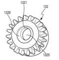
ここで、第一の実施の形態において、前記回転部材は、カムを備えたセレクタコグである、としてもよい。Here, in the first embodiment, the rotating member may be a selector cog equipped with a cam.
ここで、好ましくは、前記カムは、周方向一部に間隙(1321)を有した円弧状に形成され、カム高さは、円弧の両端が低く、中央部が高いアーチ状をしていて、前記カムは、少なくとも1つの間隙によって遮断され、前記カムがチューブと接触すると、流体の流れを遮断するようにそれを挟み込み、チューブが前記間隙に対向した位置に存在すると、流体を流すことを可能としてもよい。Here, preferably, the cam is formed in an arc shape with a gap (1321) in a portion of the circumference, the cam height is an arch shape with low ends and high center, and the cam is blocked by at least one gap, and when the cam comes into contact with the tube, it pinches it to block the flow of fluid, and when the tube is in a position facing the gap, it may allow the fluid to flow.
ここで、変形例において、前記カムは、前記セレクタコグの中央孔の径方向に形成され、前記チューブは、前記中央孔を通過し、前記カムは、より大きな径の部分を含み、チューブが小さな径の部分と協働する際に、チューブが挟まれ、チューブが、より大きな径の部分と協働する際に、チューブが挟まれることがない、としてもよい。In a modified example, the cam may be formed in the radial direction of the central hole of the selector cog, the tube may pass through the central hole, and the cam may include a portion of a larger diameter, such that the tube is pinched when the tube cooperates with the portion of the smaller diameter, and is not pinched when the tube cooperates with the portion of the larger diameter.
ここで、第二の実施の形態において、前記回転部材は、カム要素を備えたシャフトである、としてもよい。Here, in the second embodiment, the rotating member may be a shaft equipped with a cam element.
ここで、好ましくは、前記カム要素は、複数の可撓性ブレードを備えるピンチ部材と協働し、前記可撓性ブレードは、各リザーバチューブに対して1つずつ存在し、カム要素が前記ピンチ部材の可撓性ブレードを変形させると、前記可撓性ブレードは、その対応するチューブを挟み込んで、流体の流れを遮断してもよい。Here, preferably, the cam element cooperates with a pinch member having a plurality of flexible blades, one for each reservoir tube, and when the cam element deforms the flexible blades of the pinch member, the flexible blades may pinch their corresponding tubes to block the flow of fluid.
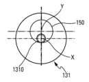
ここで、好ましくは、前記ディスペンサシステムは、クランクシャフト上で回転するように取り付けられたリングを含むペリスタポンプを備え、前記リングは、前記クランクシャフトの回転軸(X)に対してオフセットされた回転軸(Y)の周りを回転し、前記クランクシャフトの周囲に延伸するチューブの一部分を徐々に圧縮してもよい。Here, preferably, the dispenser system comprises a peristaltic pump including a ring mounted for rotation on a crankshaft, the ring rotating about an axis of rotation (Y) offset relative to the axis of rotation (X) of the crankshaft, and may gradually compress a portion of a tube extending around the crankshaft.
ここで、好ましくは、前記リングは、前記クランクシャフトの中心シリンダの周囲を回転してもよい。Here, preferably, the ring rotates around the central cylinder of the crankshaft.
ここで、好ましくは、各リザーバは、1mL(ミリリットル)-10mLの範囲の、好ましくは、約3mLの流体内容物を収容してもよい。Here, preferably, each reservoir may contain a fluid content in the range of 1 mL (milliliter)-10 mL, preferably about 3 mL.
ここで、好ましくは、前記器具は、電子モジュールを含む、としてもよい。Here, preferably, the device may include an electronic module.
ここで、好ましくは、前記電子モジュールは、電源、特に、オプションとして充電可能なバッテリ、マイクロプロセッサ、記憶手段、信号送受信手段及びモータを備える、としてもよい。Here, preferably, the electronic module may comprise a power source, in particular an optionally rechargeable battery, a microprocessor, memory means, signal transmission/reception means and a motor.
ここで、好ましくは、前記電子モジュールは、再利用可能であり、器具上で取り外し可能な方法で取り付けられる、としてもよい。Here, preferably, the electronic module is reusable and may be mounted in a removable manner on the instrument.
これらの又は他の特性及び利点は、限定されない例として、また、添付図面を参照して、以下の詳細な説明から、より明確に明らかになる。These and other characteristics and advantages will become more clearly apparent from the following detailed description, given by way of non-limiting example and with reference to the accompanying drawings, in which:
本発明は、典型的には、数ミリリットル程度の、さらに典型的には、1mLから10mLの範囲、例えば、3mLの、比較的大容量の流体を投与するように特に適合された注射器具に関する。本発明の本器具は、また、比較的粘性のある流体を投与するように適合している。The present invention relates to an injection device that is particularly adapted to administer relatively large volumes of fluid, typically on the order of a few milliliters, more typically in the range of 1 mL to 10 mL, e.g. 3 mL. The device of the present invention is also adapted to administer relatively viscous fluids.
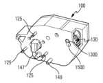
好ましくは、本器具は、複数のモジュールを備える。従って、図1、図2(a)、図3及び図4に示す例では、本器具は、以下において、切替モジュール100及びリザーバモジュール200として参照されるメインモジュール並びに電子モジュール300を備える。切替モジュール100及びリザーバモジュール200は、好ましくは使い捨て可能であり、一方、電子モジュール300は、好ましくは、再利用可能である。図2(b)に示す変形例では、切替モジュール100及びリザーバモジュール200は、単一のモジュールを構成する。Preferably, the device comprises a plurality of modules. Thus, in the example shown in Figures 1, 2(a), 3 and 4, the device comprises a main module, hereinafter referred to as a
本実施形態では、リザーバモジュール200は、好ましくは、特に空間を節約するように、三角形に配置された3個のリザーバ210を備えるが、当然ながら、例えば、単一のリザーバ、2個のリザーバ又は3個以上のリザーバのように、任意の数のリザーバを備えることができる。複数のリザーバ210を備える場合、図中の複数の例のように、前記複数のリザーバは、同一又は異なる薬品を収容してもよい。図2(b)及び図38-図41に示す例では、複数のリザーバ210の数は、3個であり、三角形ではなく、並んで配置されている。従来の方法では、各リザーバ210は、作動中に、当該リザーバ内で移動するピストンを含んでもよい。In this embodiment, the
1個又は複数のリザーバを有する器具を使用することにより、特に、以下の利点を提供することが可能になる:
- 異なる容量の投与を必要とする可能性のある2つ以上のタイプの流体のための単一の器具;
- カクテル又は2つ以上の流体の混合物を投与する可能性;
- 鎮痛薬(麻酔薬、酸中和剤など)と注射薬とを関連づける可能性;
- 異なる投薬治療の頻度を有する可能性;例えば、複数の異なる薬品を服用する第1シーケンスS1、続いて単一の薬品を服用する第2シーケンスS2など;
- 数種類の治療のための注射器具の標準化の可能性;
- 器具の開発コストの低減;
- 流体の調合を調整する可能性;
- 様々な流体製剤を1つの器具に収納することができる;
- 注射回数の減少。 The use of a device with one or more reservoirs makes it possible to provide, inter alia, the following advantages:
- a single device for two or more types of fluids that may require administration of different volumes;
the possibility of administering a cocktail or a mixture of two or more fluids;
- possible association of analgesics (anesthetics, acid neutralizers, etc.) with injectable drugs;
the possibility of having different medication frequencies; for example a first sequence S1 of taking several different drugs followed by a second sequence S2 of taking a single drug;
- the possibility of standardizing injection equipment for several types of treatment;
- reducing the cost of developing instruments;
- possibility to adjust the fluid mix;
- Various fluid formulations can be contained in one device;
- Fewer injections.
図2(a)、図3及び図4は、本器具の使用中の連続した工程を示す。Figures 2(a), 3 and 4 show the successive steps during use of the device.
このように、図2(a)に見られるように、最初に、電子モジュール300及びリザーバモジュール200は、切替モジュール100上に取り付けられる。最初に電子モジュール300を取り付ける、又は、逆に、最初にリザーバモジュール200を取り付ける形態で実施することができる。好ましくは、いったん組み立てると、電子モジュール300を作動させる形態で実施することができ、その結果、エネルギー消費が少ない「スタンバイ」又はOFFモードから、もしあれば、それが作動可能である「アクティブ」モードへと移行することができる。代わりに、電子モジュール300は、前記リザーバモジュールが最後に組み立てられたとき、リザーバモジュール200の組み立て中に、起動されてもよい。オプションとして、図3に示すように、本器具が注射部位SIに当てられるときにのみ、電子モジュールを起動するように、本器具は、注射部位SIに当てられる表面にセンサ102を含むようにしてもよい。Thus, as seen in FIG. 2(a), first the
図2(b)に示す変形例では、本器具は、電子モジュール300とメインモジュールとの2つのモジュールのみを含むとしてもよい。メインモジュールは、切替モジュール100とリザーバモジュール200との両方を組み合わせてなる。In a variation shown in FIG. 2(b), the device may include only two modules: an
本器具が組み立てられると、切替モジュール100の後面に設けられた保護フィルム101が除去され(図3)、本器具が注射部位SIに当てられ(図4)、そこで、公知の方法により、適切な接着剤によって保持される。Once the device is assembled, the
次いで、利用者は、切替モジュール100又は電子モジュール300のアクチュエータボタン110を押して、本器具を作動させ、注射部位SIに流体を注射する。The user then presses the
好ましくは、本器具は、電子モジュール300によって、制御される。特に、電子モジュールは、電源、特にオプションとして充電可能なバッテリ、マイクロプロセッサ、記憶手段及び信号送受信手段を備える。Preferably, the device is controlled by an
好ましくは、本器具は、独立している。しかし、本器具は、特に、流体を供給すべき1又は複数のリザーバの選択及び/又は順序、投与速度などに関して、当該器具の作動中に、制御命令を電子モジュールに送信することによって、遠隔制御することができる。Preferably, the device is self-contained. However, the device can be remotely controlled by sending control instructions to the electronic module during operation of the device, particularly with regard to the selection and/or sequence of one or more reservoirs to which fluid should be delivered, the rate of administration, etc.
好ましくは、電子モジュールは、作動サイクルを実行するように、本器具の可動要素を作動させるモータ350(図7)を制御する。Preferably, the electronic module controls a motor 350 (FIG. 7) that operates the moving elements of the instrument to perform the actuation cycle.
電子モジュール300の電子手段は、本器具の動作に関与するが、本器具の本質的な特性を形成するものではなく、当業者に周知の如何なる方法でも製造することができるので、ここでは、より詳細には説明しない。The electronic means of the
変形例では、電子モジュールの代わりに及び電子モジュールを置き換えて、本器具を作動させるために、例えば、1つ以上のバネを使用する、機械的アクチュエータシステムの形態で実施することが可能である。In a variant, instead of and replacing the electronic module, the device can be implemented in the form of a mechanical actuator system, for example using one or more springs, to actuate the device.
注射の終了時に、本器具は注射部位SIから取り外され、電子モジュール300は、特に、再利用できるように、本器具から取り外され、切替モジュール100及びリザーバモジュール200は廃棄される。Upon completion of the injection, the device is removed from the injection site SI, the
図5は、この実施形態における、切替モジュール100の本体上で、軸を中心として揺動(枢動)するレバーの形態のアクチュエータボタン110の一例を示す。前記レバーを枢動させることにより、まず、注射針120を注射部位内に挿入させ、注射針120を通して流体を投与するように、本器具を作動させる。Figure 5 shows an example of an
好ましくは、作動前に、1又は複数のリザーバ210は、隔壁形成膜によって閉じられている。作動中にプライミング針125によって、隔壁形成膜に穴が開けられる。図7及び図8に示す例では、切替モジュール100は、各リザーバ210に対して1本ずつ、合計で3本のプライミング針125を含む。リザーバモジュール200が切替モジュール100に取り付けられたときに、1又は複数の隔壁形成膜に穴を開けることによってプライミング(呼び水)する。Preferably, prior to actuation, one or
図7及び図8の例に示すように、複数のリザーバ210が用いられる場合、すべてのリザーバ210のプライミング針125は、単一の注射針120(図15)に結合される。As shown in the examples of Figures 7 and 8, when
切替モジュール100は、いくつかの好ましい実施形態を参照して説明される。The
好ましくは、切替モジュール100は、以下のように動作する:
- 流体を供給すべき1又は複数のリザーバ210を選択し、及び
- 選択された1又は複数のリザーバ210に含まれる薬品を投与する。 Preferably, the
- selecting one or
1又は複数のリザーバ210は、各リザーバに接続されたチューブを挟む又は閉じることによって選択される。One or
選択された1又は複数のリザーバ210の内容物は、好ましくは、図18-図23を参照してより完全に後述される、ペリスタポンプ150の形態のディスペンサシステムの手段によって投与される。The contents of the selected reservoir(s) 210 are preferably administered by means of a dispenser system in the form of a
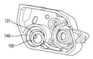
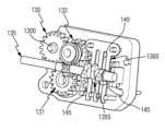
好ましくは、切替モジュール100は、コグシステム131、132、133、134、135を備えた単一のロータリアクチュエータ130を含む(図24-図30)。アクチュエータ130が第一の回転方向に回ると、それは、流体を供給すべき1又は複数のリザーバ210の選択を起動し、それが逆方向に回ると、ディスペンサシステム、すなわち、図18-図23の例におけるペリスタポンプ150を作動させる。好ましくは、前記アクチュエータ130を回動させるのは、図7に示される電子モジュール300のモータ350である。Preferably, the
アクチュエータ130は、切替モジュール100の本体内の長円形の開口1500を貫通して延在する中央ピン1300を含む。The
アクチュエータ130の回転方向に依存して、中央ピン1300は、長円形の開口1500の一方の端部又は他方の端部から平行状態でシフトする。Depending on the direction of rotation of the
第一の端部では、図26に見られるように、アクチュエータ130は、特に中間コグ133を介して、セレクタコグ132と噛み合い、流体を供給すべき1又は複数のリザーバの選択を作動させる。At a first end, as seen in FIG. 26, the
他端では、図25に見られるように、アクチュエータ130は、ペリスタポンプを作動させるように、クランクシャフト131と噛み合う。At the other end, as seen in FIG. 25, the
図25、図26及び図38、図39の例では、アクチュエータ130を一方の回転方向又は他方の回転方向に回転させるように、駆動コグ134が設けられている。駆動コグ134は、モータに接続してもよい。変形例では、駆動コグを省略することができ、モータをアクチュエータ130に直接接続することができる。25-26 and 38-39, a
このように、アクチュエータ130は、揺動コグである。それは、その回転方向の機能として、及び上述の他の回転要素からの反対向きのトルクの結果として、長円形の開口1500に沿った平行移動においてシフトされる。Thus, the
好ましくは、切替モジュール100は、各々のリザーバ210から出ている各チューブ145を含むマニホールド140も含む(図6)。各チューブ145は、一端がそのリザーバ210に接続され、他端がディスペンサシステムに接続され、具体的には、この実施形態では、一組のチューブ147、148、149を介して、ペリスタポンプ150、次いで注射針120(図5)に接続される。Preferably, the
複数のリザーバ210が存在する場合、特に、図中の例のように、3個のリザーバ内において、複数のチューブ145は、注射針120内に放出するように、ディスペンサシステムから下流で、ともに結合される。チューブ145、147、148、149のセットは、配管を形成し、そのいくつかの変形例が、特に、図6、図15及び図30に示される。When
好ましくは、チューブ145、147、148、149は、投与される流体に適合する材料、例えば、カテーテルを製造するために一般的に使用される材料から作られる。Preferably,
好ましくは、作動中に流体を供給すべき1又は複数のリザーバ210は、リザーバ210に接続された1つ以上のチューブ145を挟むこと又は平坦化することによって、選択される。チューブ145が「挟まれる」と、流体がチューブに沿って流れることが妨げられる。対応するリザーバ210の内容物は、注射針120に向かって流れることができない。Preferably, one or
1又は複数のチューブ145は、可動部、特に、回転部材上に、形成されるカム手段によって挟まれることが好ましい。It is preferable that one or
図11は、挟まれていないチューブ145を示し、その結果、流体は、チューブ145に沿って流れることができる。一方、図12は、挟まれ又は平坦化されたチューブ145を示す。従って、流体は、流れることができない。Figure 11 shows the
図11-図16に示す例では、単一のロータリアクチュエータ130のコグシステムの一部を形成するセレクタコグ132は、周方向一部に間隙(1321)を有した円弧状に形成され、カム高さは、円弧の両端が低く、中央部が高いアーチ状をしたカム1320を含む。図16に見られるように、カム1320の前記突起は、間隙1321によって中断している。カム1320がチューブ145と接触すると、流体の流れを遮断するように、カム1320は、チューブ145を挟む。これに対して、チューブ145が間隙1321と対向した位置に存在すると、流動が可能である。In the example shown in Figures 11-16, the
図13及び図14は、3本のチューブ145のうちの2本が挟まれ、1本のチューブ145が「開放」されている例を示す。ポンプが作動すると、開放されたチューブ145に接続されているリザーバ210から、薬品が吸引される。Figures 13 and 14 show an example in which two of the three
当然、図27-図41に示すように、他の変形された実施形態を示す他の構成も可能である。Of course, other configurations are possible, showing other modified embodiments, as shown in Figures 27-41.
従って、図27-図29において、カム1320は、セレクタコグ132の中央孔1325内に半径方向に形成される。カム1320は、より大きな直径の部分1321を含む。この例において、3本存在するチューブ145は、中央孔1325を通過する。1本のチューブ145がより小さな直径の部分と協働すると、当該チューブ145は、挟まれる。一方、当該チューブ145がより大きな直径の部分1321と協働すると、当該チューブ145は、挟まれない。27-29, the
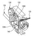
図30-図37は、別の実施形態を示す。この実施形態では、セレクタコグは、複数のカム要素1350を支持する回転セレクタシャフト135に置き換えられる。具体的には、図示の例では、3個のカム要素1350が示されている。ピンチ部材1360が、複数のカム要素1350と複数のチューブ145との間に設けられている。ピンチ部材1360は、好ましくは、各チューブ145に対して1つの可撓性ブレードを備え、当該ブレードは、セレクタシャフト135のカム要素1350によって、弾性変形される。これは、カム要素がチューブに対して擦れることを回避し、これは、それら(ブレード)を変形させるという欠点を有し、各チューブ145の挟み込みをあまり効果的にしないという欠点を有し得る。Figures 30-37 show another embodiment. In this embodiment, the selector cog is replaced by a
図32及び35は、挟まれないチューブ145を示し、その結果、チューブ145は、流体の流れを通過させることができる。一方、図33及び34は、ピンチ部材1360のブレードによって挟まれ又は平坦化されたチューブ145を示す。ピンチ部材1360自体がセレクタシャフト135のカム要素1350によって押され、従って、流体が流れることはできない。Figures 32 and 35 show the
図38-図41の例は、3個のリザーバが並行して配置されていて、図30-図37の実施の形態と非常に類似している。図39に示すように、同じ平面内に、3本のプライミング針125が平行に配置されている。The example of Figs. 38-41 has three reservoirs arranged in parallel and is very similar to the embodiment of Figs. 30-37. As shown in Fig. 39, three priming
図示した実施例では、ピンチ部材1360は、単一のピース部品を形成する。しかし、変形例では、それぞれが可撓性ブレードによって形成される複数の別個のピンチ部材の形態で実施することが可能である。In the illustrated embodiment, the
ディスペンサシステムは、ペリスタポンプを備えることが好ましい。前記ペリスタポンプは、リング150(図6、図22-図23)を備え、前記クランクシャフト131の回転軸Xに対してオフセットされた回転軸Yを中心としてクランクシャフト131を作動(turn on)する(図22-図23)。好ましくは、図22に見られるように、クランクシャフト131の回転軸Xは、リング150がその周囲を回ることができる中心軸方向シリンダ1310によって形成される。マニホールド140から注射針120へと進むチューブ148の一部は、クランクシャフト131の周囲に延び、その結果、リング150は、そのオフセット回転軸Yを中心に回るにつれて、クランクシャフト131の前記中心軸方向シリンダ1310を中心に回り、チューブ148に沿って圧縮を移動させ、それによって、該チューブ148内を通過する流体が投与されるようになる。図19-図21は、ペリスタポンプがどのように作動するかを示す。The dispenser system preferably comprises a peristaltic pump, which comprises a ring 150 (FIGS. 6, 22-23) and turns on the
流体の投与が終了すると、注射針120は、好ましくは自動的に、本器具内に引き込まれる。流体の投与の終了は、機械的及び/又はソフトウェアモニタリングによって、識別することができる。Once fluid administration is complete, the
図に示される実施の形態は、1個、2個又は3個のリザーバ210を含むように適合された器具を示す。リザーバモジュール200上のマスクを使用するための準備を行うことができる。器具の組み立て中に、リザーバの存在によってマスクが穿孔/貫通される。リザーバが存在しないとき、そのマスクは、チューブのそれぞれの分岐をシールするように作用し、投与中に、薬品が漏れることを防止する。The illustrated embodiment shows a device adapted to include one, two or three
上述の実施の形態は、特に、以下の利点を提供する:
- 流体を投与する速度は、個々の治療を最適化するように、調節されてもよく、また、時間の経過とともに変化してもよく、
- 複数のリザーバは、異なる速度及び異なる瞬間に、投与され得る薬品の組み合わせを使用することを可能にする。 The above-described embodiments provide, inter alia, the following advantages:
- the rate at which fluid is administered may be adjusted and may vary over time to optimize individual treatment;
- Multiple reservoirs allow the use of drug combinations that can be administered at different rates and at different times.
同時注射又は連続注射の使用は、次のために、複数のカートリッジを有するシステムにおいて適用することができる:
- 流体の流量を減らし、患者の痛みを和らげ、
- ある種の薬品のカクテルの調合の効果を改善することを可能にする。 The use of simultaneous or sequential injections can be applied in systems with multiple cartridges for:
- Reduces fluid flow, relieving pain for the patient,
- It makes it possible to improve the effect of the preparation of certain drug cocktails.
いくつかの好ましい実施の形態及び変形例を参照して、本発明について、上述したが、添付の特許請求の範囲によって定義されるように、本発明の範囲を超えることなく、当然のことながら、当業者であれば、任意の変形例を適用することができる。Although the present invention has been described above with reference to some preferred embodiments and modifications, it will be appreciated that those skilled in the art may make any modifications without going beyond the scope of the present invention as defined by the appended claims.
Claims (16)
Translated fromJapanese注射部位(SI)に接触するための本体、
複数の流体リザーバ(210)、
前記複数の流体リザーバと同数のチューブ(145)、
1個又は複数のリザーバ(210)の内容物を内部に注射するために、注射部位(SI)に貫通する注射針(120)を備え、
各チューブ(145)の一端は、対応する流体リサーバ(210)に接続され、
前記器具は、さらに、単一のロータリアクチュエータ(130)を備えることを特徴とし、
前記単一のロータリアクチュエータ(130)が第1の回転方向に回るとき、流体を供給すべきリザーバ(210)の選択を起動し、それが逆方向に回るとき、ディスペンサシステム、特に、ペリスタポンプ(150)を作動させ、
前記各チューブ(145)の他端は、合流して、前記ペリスタポンプ(150)を介して、注射針(120)に接続し、
前記ロータリアクチュエータ(130)は、本体の長円形の開口(1500)を貫通して延在する中央ピン(1300)を含み、それによって揺動コグを形成し、
前記ロータリアクチュエータ(130)は、第1の回転方向に回るとき、前記供給が選択されたリザーバ(210)に対応するチューブ(145)を開放し、選択されなかったリザーバに対応するチューブ(145)を閉鎖し、逆方向に回るとき、揺動コグの作用により、各チューブ(145)の前記開放及び前記閉鎖の状態は、維持される
流体注射器具。 1. A fluid injection device comprising:
a body for contacting an injection site (SI);
A plurality of fluid reservoirs (210);
a number of tubes (145) equal to the number of said fluid reservoirs;
an injection needle (120) penetrating an injection site (SI) for injecting the contents of one or more reservoirs (210) therein;
One end of each tube (145) is connected to a corresponding fluid reservoir (210);
The instrument is further characterized in that it comprises a single rotary actuator (130);
said single rotary actuator (130) activates the selection of a reservoir (210) to be dispensed with fluid when it rotates in a first rotational direction and actuates the dispenser system, in particular the peristaltic pump (150), when it rotates in the opposite direction;
The other ends of thetubes (145) join together and are connected to the injection needle (120) via the peristaltic pump (150);
Therotary actuator (130) includes a central pin (1300) extending through an oblong opening (1500) in the body, thereby forming a rocker cog;
Whenthe rotary actuator (130) rotates in a first rotational direction, it opens the tubes (145) corresponding to the supply selected reservoir (210) and closes the tubes (145) corresponding to the non-selected reservoirs, and when it rotates in the opposite direction, the open and closed states of each tube (145) are maintained by the action of a rocking cog.
ことを特徴とする請求項1に記載の流体注射器具。 The fluid injection device according to claim 1, characterized in that, whenthe rotary actuator (130) is present at a first end of the oval opening (1500), it engages with a rotating member (132, 135), in particular via an intermediate cog (133), for actuating the selection of a reservoir (210) to supply fluid, and, when it is present at the other end of the oval opening (1500), it engages with a crankshaft (131) for actuating a peristaltic pump (150).
各チューブ(145)は、一端において、プライミング針(125)に接続し、他端において、マニホールド(140)に接続し、
前記マニホールド(140)は、チューブ(148)の一部分によって、前記注射針に接続されている
ことを特徴とする請求項1又は2に記載の流体注射器具。 Prior to administering the liquid, each priming needle (125) corresponds to a respective reservoir (210) and penetrates that reservoir (210);
Each tube (145) connects at one end to a priming needle (125) and at the other end to a manifold (140);
3. The fluid injection device of claim 1 or 2, wherein the manifold (140) is connected to the injection needle by a portion of tubing (148).
前記リザーバ(210)の内容物は、次の作動中に投与され、
前記リザーバ選択手段は、回転部材(132、135)を備え、
前記回転部材(132、135)は、各チューブ(145)を通る流体の流れを開閉するように、リザーバ(210)のチューブ(145)と協働するように構成されたカム手段(1320、1350)を備える
ことを特徴とする請求項3に記載の流体注射器具。 a reservoir selection means for selecting one or more reservoirs (210);
The contents of said reservoir (210) are administered during the next actuation,
The reservoir selection means comprises a rotating member (132, 135);
4. The fluid injection device according to claim 3, characterized in that the rotating members (132, 135) comprise cam means (1320, 1350) configured to cooperate with the tubes (145) of the reservoir (210) to open and close the flow of fluid through each tube (145).
ことを特徴とする請求項4に記載の流体注射器具。 5. The fluid injection device according to claim 4, characterized in that the rotating member is a selector cog (132) equipped with a cam means (1320).
ことを特徴とする請求項5に記載の流体注射器具。 The fluid injection device according to claim 5, characterized in that the cam means (1320) is formed in an arc shape having a gap (1321) in a portion of the circumferential direction, the cam height is an arch shape with low ends of the arc and high in the center, and when the cam means (1320) comes into contact with the tube (145), it pinches it to block the flow of fluid, and when the tube (145) is in a position opposite the gap (1321), it allows the fluid to flow.
ことを特徴とする請求項5に記載の流体注射器具。 The fluid injection device according to claim 5, characterized in that the cam means (1320) is formed in the radial direction of a central hole (1325) of the selector cog (132), the tube (145) passes through the central hole (1325), and the cammeans (1320) includes a larger diameter portion (1321), such that when the tube (145) cooperates with the smaller diameter portion, the tube (145) is pinched, and when the tube (145) cooperates with the larger diameter portion (1321), the tube (145) is not pinched.
ことを特徴とする請求項4に記載の流体注射器具。 The rotating member is a shaft (135) equipped with a cam means (1350).
5. A fluid injection device according to claim 4.
ことを特徴とする請求項8に記載の流体注射器具。 The fluid injection device of claim 8, characterized in that the cam means (1350) cooperates with a pinch member (1360) having a plurality of flexible blades, one for each reservoir tube (145), and when the cam means (1350) deforms the flexible blades of the pinch member, the flexible blades pinch their corresponding tubes (145) to block the flow of fluid.
前記リング(150)は、前記クランクシャフト(131)の回転軸(X)に対してオフセットされた回転軸(Y)の周りを回転し、前記クランクシャフト(131)の周囲に延伸するチューブ(148)の一部分を徐々に圧縮する
ことを特徴とする請求項3~9のいずれかに記載の流体注射器具。 The dispenser system comprises a peristaltic pump including a ring (150) mounted for rotation on a crankshaft (131);
The fluid injection device according to any one of claims 3 to 9, characterized in that the ring (150) rotates about a rotation axis (Y) offset with respect to the rotation axis (X) of the crankshaft (131) to gradually compress a portion of a tube (148) extending around the crankshaft (131).
ことを特徴とする請求項10に記載の流体注射器具。 The fluid injection device according to claim 10, characterized in that the ring (150) rotates around a central cylinder (1310) of the crankshaft (131).
ことを特徴とする請求項1~11のいずれかに記載の流体注射器具。 Fluid injection device according to any one of the preceding claims, characterized in that each reservoir contains a fluid content in the range 1mL-10mL, preferably about 3mL.
ことを特徴とする請求項1~12のいずれかに記載の流体注射器具。 Fluid injection device according to any one of the preceding claims, characterized in that the device includes an electronic module (300).
電源、特に、オプションとして充電可能なバッテリ、
マイクロプロセッサ、
記憶手段、
信号送受信手段及び
モータ
を備えることを特徴とする請求項13に記載の流体注射器具。 The electronic module (300) comprises:
A power source, in particular an optionally rechargeable battery;
Microprocessor,
Storage means,
14. A fluid injection device according to claim 13, further comprising a signal transmitting/receiving means and a motor.
ことを特徴とする請求項13又は請求項14に記載の流体注射器具。 Fluid injection device according to claim 13 or 14, characterized in that the electronic module (300) is reusable and is mounted in a removable manner on the device.
注射部位(SI)に接触するための本体、
複数の流体リザーバ(210)、
前記複数の流体リザーバと同数のチューブ(145)、
1個又は複数のリザーバ(210)の内容物を内部に注射するために、注射部位(SI)に貫通する注射針(120)を備え、
各チューブ(145)の一端は、対応する流体リサーバ(210)に接続され、
前記器具は、さらに、単一のロータリアクチュエータ(130)を備えることを特徴とし、
前記単一のロータリアクチュエータ(130)が第1の回転方向に回るとき、流体を供給すべきリザーバ(210)の選択を起動し、それが逆方向に回るとき、ディスペンサシステム、特に、ペリスタポンプ(150)を作動させ、
前記各チューブ(145)の他端は、合流して、前記ペリスタポンプ(150)を介して、注射針(120)に接続し、
前記ロータリアクチュエータ(130)は、本体の長円形の開口(1500)を貫通して延在する中央ピン(1300)を含み、それによって揺動コグを形成し、
さらに、1個又は複数のリザーバ(210)を選択するリザーバ選択手段を含み、
前記リザーバ(210)の内容物は、次の作動中に投与され、
前記リザーバ選択手段は、回転部材(132、135)を備え、
前記回転部材(132、135)は、各チューブ(145)を通る流体の流れを開閉するように、リザーバ(210)のチューブ(145)と協働するように構成されたカム手段(1320、1350)を備え、
前記回転部材は、カム手段(1320)を備えたセレクタコグ(132)であり、
前記カム手段(1320)は、前記セレクタコグ(132)の中央孔(1325)の径方向に形成され、前記チューブ(145)は、前記中央孔(1325)を通過し、前記カム手段(1320)は、より大きな径の部分(1321)を含み、チューブ(145)が小さな径の部分と協働する際に、チューブ(145)が挟まれ、チューブ(145)が、より大きな径の部分(1321)と協働する際に、チューブ(145)が挟まれることがない
ことを特徴とする流体注射器具。 1. A fluid injection device comprising:
a body for contacting an injection site (SI);
A plurality of fluid reservoirs (210);
a number of tubes (145) equal to the number of said fluid reservoirs;
an injection needle (120) penetrating an injection site (SI) for injecting the contents of one or more reservoirs (210) therein;
One end of each tube (145) is connected to a corresponding fluid reservoir (210);
The instrument is further characterized in that it comprises a single rotary actuator (130);
said single rotary actuator (130) activates the selection of a reservoir (210) to be dispensed with fluid when it rotates in a first rotational direction and actuates the dispenser system, in particular the peristaltic pump (150), when it rotates in the opposite direction;
The other ends of the tubes (145) join together and are connected to the injection needle (120) via the peristaltic pump (150);
Therotary actuator (130) includes a central pin (1300) extending through an oblong opening (1500) in the body, thereby forming a rocker cog;
further comprising a reservoir selection means for selecting one or more reservoirs (210);
The contents of said reservoir (210) are administered during the next actuation,
The reservoir selection means comprises a rotating member (132, 135);
said rotating members (132, 135) comprising cam means (1320, 1350) configured to cooperate with the tubes (145) of the reservoir (210) to open and close the flow of fluid through each tube (145);
said rotating member being a selector cog (132) equipped with a cam means (1320);
A fluid injection device, characterized in that the cam means (1320) is formed in the radial direction of a central hole (1325) of the selector cog (132), the tube (145) passes through the central hole (1325), the cam means (1320) includes a larger diameter portion (1321), and when the tube (145) cooperates with the smaller diameter portion (1321), the tube (145) is pinched, and when the tube (145) cooperates with the larger diameter portion (1321), the tube (145) is not pinched.
Applications Claiming Priority (3)
| Application Number | Priority Date | Filing Date | Title |
|---|---|---|---|
| FR1856496AFR3083708B1 (en) | 2018-07-13 | 2018-07-13 | FLUID PRODUCT INJECTION DEVICE. |
| FR1856496 | 2018-07-13 | ||
| PCT/FR2019/051746WO2020012132A1 (en) | 2018-07-13 | 2019-07-11 | Fluid product injection device |
Publications (2)
| Publication Number | Publication Date |
|---|---|
| JP2021524348A JP2021524348A (en) | 2021-09-13 |
| JP7465254B2true JP7465254B2 (en) | 2024-04-10 |
Family
ID=63722597
Family Applications (1)
| Application Number | Title | Priority Date | Filing Date |
|---|---|---|---|
| JP2021500914AActiveJP7465254B2 (en) | 2018-07-13 | 2019-07-11 | Fluid injection device |
Country Status (5)
| Country | Link |
|---|---|
| US (1) | US20220193332A1 (en) |
| EP (1) | EP3820547B1 (en) |
| JP (1) | JP7465254B2 (en) |
| FR (1) | FR3083708B1 (en) |
| WO (1) | WO2020012132A1 (en) |
Families Citing this family (5)
| Publication number | Priority date | Publication date | Assignee | Title |
|---|---|---|---|---|
| EP1762259B2 (en) | 2005-09-12 | 2025-01-01 | Unomedical A/S | Inserter for an infusion set with a first and second spring units |
| WO2012123274A1 (en) | 2011-03-14 | 2012-09-20 | Unomedical A/S | Inserter system with transport protection |
| US11458292B2 (en) | 2019-05-20 | 2022-10-04 | Unomedical A/S | Rotatable infusion device and methods thereof |
| FR3109318B1 (en)* | 2020-04-15 | 2023-11-10 | Syrengy | Injection syringe |
| EP4536315A1 (en)* | 2022-06-09 | 2025-04-16 | SHL Medical AG | Drug delivery control arrangement, and injector |
Citations (7)
| Publication number | Priority date | Publication date | Assignee | Title |
|---|---|---|---|---|
| JP2010501283A (en) | 2006-08-23 | 2010-01-21 | メドトロニック ミニメド インコーポレイテッド | Infusion medium delivery device and method using a drive device for driving a plunger in a storage container |
| JP2013544162A (en) | 2010-11-29 | 2013-12-12 | サノフィ−アベンティス・ドイチュラント・ゲゼルシャフト・ミット・ベシュレンクテル・ハフツング | Dosing interface member for a drug delivery device |
| JP2014012123A (en) | 2012-06-06 | 2014-01-23 | Nidec Copal Electronics Corp | Cassette for infusion pump and infusion pump |
| JP2014519900A (en) | 2011-05-25 | 2014-08-21 | サノフィ−アベンティス・ドイチュラント・ゲゼルシャフト・ミット・ベシュレンクテル・ハフツング | Drug delivery device and method for controlling the device |
| JP2017074080A (en) | 2015-10-13 | 2017-04-20 | 日立アプライアンス株式会社 | Washing machine |
| JP2017110711A (en) | 2015-12-15 | 2017-06-22 | プライムテック株式会社 | Fluid selector valve and fluid conveying cartridge |
| WO2018067734A1 (en) | 2016-10-04 | 2018-04-12 | Craig M D H Randall | Medication delivery method and device with remote control |
Family Cites Families (8)
| Publication number | Priority date | Publication date | Assignee | Title |
|---|---|---|---|---|
| ZA78674B (en)* | 1978-02-09 | 1979-09-26 | Ethor Ltd | Dispensing of fluent materials |
| AR244863A1 (en)* | 1989-09-07 | 1993-11-30 | Marcelo Alberto Hoegner | A multi-valve and the sterilising equipment that contains it. |
| PL1682203T3 (en) | 2003-10-23 | 2010-06-30 | Novo Nordisk As | Medical injection device mountable to the skin |
| US20070088271A1 (en) | 2005-10-18 | 2007-04-19 | Richards Cynthia C | Medication device |
| US9114243B2 (en)* | 2009-02-19 | 2015-08-25 | Covidien Lp | Manual valve actuator for medical fluid delivery set |
| US8382447B2 (en)* | 2009-12-31 | 2013-02-26 | Baxter International, Inc. | Shuttle pump with controlled geometry |
| WO2013070259A1 (en)* | 2011-11-08 | 2013-05-16 | Duncan David R | Compact non-electric medicament infuser |
| US20170128667A1 (en)* | 2015-11-06 | 2017-05-11 | Teleflex Medical Incorporated | Valve apparatus that regulates flow of fluid and vacuum pressure |
- 2018
- 2018-07-13FRFR1856496Apatent/FR3083708B1/enactiveActive
- 2019
- 2019-07-11WOPCT/FR2019/051746patent/WO2020012132A1/ennot_activeCeased
- 2019-07-11USUS17/259,832patent/US20220193332A1/enactivePending
- 2019-07-11JPJP2021500914Apatent/JP7465254B2/enactiveActive
- 2019-07-11EPEP19756220.0Apatent/EP3820547B1/enactiveActive
Patent Citations (7)
| Publication number | Priority date | Publication date | Assignee | Title |
|---|---|---|---|---|
| JP2010501283A (en) | 2006-08-23 | 2010-01-21 | メドトロニック ミニメド インコーポレイテッド | Infusion medium delivery device and method using a drive device for driving a plunger in a storage container |
| JP2013544162A (en) | 2010-11-29 | 2013-12-12 | サノフィ−アベンティス・ドイチュラント・ゲゼルシャフト・ミット・ベシュレンクテル・ハフツング | Dosing interface member for a drug delivery device |
| JP2014519900A (en) | 2011-05-25 | 2014-08-21 | サノフィ−アベンティス・ドイチュラント・ゲゼルシャフト・ミット・ベシュレンクテル・ハフツング | Drug delivery device and method for controlling the device |
| JP2014012123A (en) | 2012-06-06 | 2014-01-23 | Nidec Copal Electronics Corp | Cassette for infusion pump and infusion pump |
| JP2017074080A (en) | 2015-10-13 | 2017-04-20 | 日立アプライアンス株式会社 | Washing machine |
| JP2017110711A (en) | 2015-12-15 | 2017-06-22 | プライムテック株式会社 | Fluid selector valve and fluid conveying cartridge |
| WO2018067734A1 (en) | 2016-10-04 | 2018-04-12 | Craig M D H Randall | Medication delivery method and device with remote control |
Also Published As
| Publication number | Publication date |
|---|---|
| WO2020012132A1 (en) | 2020-01-16 |
| EP3820547A1 (en) | 2021-05-19 |
| EP3820547B1 (en) | 2025-04-09 |
| US20220193332A1 (en) | 2022-06-23 |
| FR3083708B1 (en) | 2023-12-08 |
| FR3083708A1 (en) | 2020-01-17 |
| JP2021524348A (en) | 2021-09-13 |
Similar Documents
| Publication | Publication Date | Title |
|---|---|---|
| JP7465254B2 (en) | Fluid injection device | |
| CN204972511U (en) | Micropump of medicine is carried through infusion | |
| AU776738B2 (en) | Multi-dose infusion pump | |
| US9889253B2 (en) | Dosing unit for an ambulatory infusion device | |
| JP4290798B2 (en) | Drug delivery pen | |
| CN100563738C (en) | Injection device with credit card size | |
| FI107434B (en) | Osmotpumpar | |
| US10695487B2 (en) | Controlled delivery drive mechanisms for drug delivery pumps | |
| US6974446B2 (en) | Storage container comprising a dosing means for dispensing an injectable product to an injection device in doses | |
| US20150065958A1 (en) | Dosing Unit for an Ambulatory Infusion Device | |
| US20040153032A1 (en) | Dispenser for patient infusion device | |
| JP7405741B2 (en) | Sliding syringe cap for separate filling and delivery | |
| EP2283885A1 (en) | Dosing unit for an injection device | |
| HU226223B1 (en) | Injector device | |
| JP6855456B2 (en) | Administration unit with valve clutch device and valve clutch device | |
| JP7514821B2 (en) | Fluid injection device | |
| JP6963544B2 (en) | Administration unit with low radial sealing during storage | |
| JP7394108B2 (en) | fluid injection equipment | |
| JP2023506828A (en) | fixed dose injection device | |
| EP2750735B1 (en) | Dosing unit for an ambulatory infusion device | |
| EP2750734A1 (en) | Dosing unit for an ambulatory infusion device |
Legal Events
| Date | Code | Title | Description |
|---|---|---|---|
| A529 | Written submission of copy of amendment under article 34 pct | Free format text:JAPANESE INTERMEDIATE CODE: A529 Effective date:20210210 | |
| A621 | Written request for application examination | Free format text:JAPANESE INTERMEDIATE CODE: A621 Effective date:20220708 | |
| A977 | Report on retrieval | Free format text:JAPANESE INTERMEDIATE CODE: A971007 Effective date:20230619 | |
| A131 | Notification of reasons for refusal | Free format text:JAPANESE INTERMEDIATE CODE: A131 Effective date:20230627 | |
| A521 | Request for written amendment filed | Free format text:JAPANESE INTERMEDIATE CODE: A523 Effective date:20230802 | |
| A131 | Notification of reasons for refusal | Free format text:JAPANESE INTERMEDIATE CODE: A131 Effective date:20231114 | |
| A521 | Request for written amendment filed | Free format text:JAPANESE INTERMEDIATE CODE: A523 Effective date:20240208 | |
| TRDD | Decision of grant or rejection written | ||
| A01 | Written decision to grant a patent or to grant a registration (utility model) | Free format text:JAPANESE INTERMEDIATE CODE: A01 Effective date:20240312 | |
| A61 | First payment of annual fees (during grant procedure) | Free format text:JAPANESE INTERMEDIATE CODE: A61 Effective date:20240329 | |
| R150 | Certificate of patent or registration of utility model | Ref document number:7465254 Country of ref document:JP Free format text:JAPANESE INTERMEDIATE CODE: R150 |