JP7465133B2 - Information processing device and information processing method - Google Patents
Information processing device and information processing methodDownload PDFInfo
- Publication number
- JP7465133B2 JP7465133B2JP2020056622AJP2020056622AJP7465133B2JP 7465133 B2JP7465133 B2JP 7465133B2JP 2020056622 AJP2020056622 AJP 2020056622AJP 2020056622 AJP2020056622 AJP 2020056622AJP 7465133 B2JP7465133 B2JP 7465133B2
- Authority
- JP
- Japan
- Prior art keywords
- environment map
- image
- polyhedron
- information processing
- mapped
- Prior art date
- Legal status (The legal status is an assumption and is not a legal conclusion. Google has not performed a legal analysis and makes no representation as to the accuracy of the status listed.)
- Active
Links
Images


Landscapes
- Image Generation (AREA)
- User Interface Of Digital Computer (AREA)
Description
Translated fromJapanese本発明は、複合現実空間を提供するための技術に関するものである。The present invention relates to technology for providing mixed reality spaces.
近年、現実空間と仮想空間とのつなぎ目のない結合を目的とした、複合現実感(Mixed Reality:MR)システムの開発が盛んに行われている。MRシステムの研究の進展に伴い、特許文献1や非特許文献1のように現実物体と仮想物体の合成を目的とした、マスキング技術も提案されている。In recent years, there has been active development of mixed reality (MR) systems aimed at seamlessly combining real and virtual spaces. As research into MR systems progresses, masking techniques have also been proposed, such as those in Patent Document 1 and Non-Patent Document 1, which aim to synthesize real and virtual objects.
現実空間と仮想空間の融合性を高める方法の一つとして、金属のように表面に光沢がある仮想物体を複合現実空間で提示する際、仮想物体の周囲に存在する現実空間の景色が、仮想物体の表面に反射して映り込む現象の再現が挙げられる。このような映り込みを正確に実現するためには、観察者に提示する複合現実空間の画像の画素に対応するすべての光線の伝播を物理法則に従ってシミュレートするレイトレーシングを利用する方法がある(特許文献2)。しなしながら、レイトレーシングは一般に計算量が大きいことが知られている。One method for enhancing the integration of real space and virtual space is to reproduce the phenomenon in which the scenery in real space surrounding a virtual object that has a shiny surface, such as metal, is reflected and projected onto the surface of the virtual object when the virtual object is presented in a mixed reality space. In order to accurately reproduce such reflections, there is a method that uses ray tracing, which simulates the propagation of all light rays corresponding to the pixels of the image in the mixed reality space presented to the observer according to the laws of physics (Patent Document 2). However, ray tracing is generally known to require a large amount of calculations.
映り込みを簡易的に実現する方法として、コンピュータグラフィックの分野では、古くより環境マッピングと呼ばれる方法が取られてきた。環境マッピングは、物体に映り込むと想定される周囲環境の画像を用意し、物体に対してあたかも映り込んでいるかのようにテクスチャマッピングする方法である。特許文献3では、角度を制御できる撮像装置を利用して周囲の動画像を取得し、これを環境マッピングで利用することで映り込みを実現する方法が開示されている。In the field of computer graphics, a method known as environment mapping has long been used as a simple way to achieve reflections. Environment mapping is a method in which an image of the surrounding environment that is expected to be reflected in an object is prepared, and texture mapping is performed on the object to make it appear as if it is being reflected. Patent Document 3 discloses a method of achieving reflections by acquiring moving images of the surroundings using an imaging device with a controllable angle, and using this in environment mapping.
しかしながら、一般に環境マッピングは、十分に大きな球体あるいは立方体といった多面体に周囲の様子を映した画像が貼付されていると想定し、観察者の視線が仮想物体の表面で反射した際のベクトル(以下、反射ベクトル)から該画像のどの画素の色と対応付くかを調べる方法であり、あくまで近似である。したがって、現実空間に存在する3次元物体の映り込みを正確に再現することはできず、映り込み位置が本来の位置から大きくずれることがある。本発明では、仮想物体の表面に現実空間の映り込みを実現する場合に、映り込み位置の不正確さを低減させるための技術を提供する。However, environment mapping generally assumes that an image of the surroundings is attached to a sufficiently large polyhedron such as a sphere or cube, and examines which pixel color in the image corresponds to the vector (hereinafter referred to as the reflection vector) when the observer's line of sight is reflected on the surface of the virtual object; this is merely an approximation. As a result, it is not possible to accurately reproduce the reflection of a three-dimensional object that exists in real space, and the position of the reflection may deviate significantly from the original position. This invention provides a technology for reducing the inaccuracy of the position of the reflection when real space is reflected on the surface of a virtual object.
本発明の一様態は、背景用の色画像をマッピングした多面体を第1環境マップとして生成する第1生成手段と、現実空間の色画像を取得するデバイスと移動体との間の距離に応じたサイズを有する多面体に、該デバイスが取得した該移動体の色画像をマッピングすることで得られるマッピング済み多面体を第2環境マップとして生成する第2生成手段と、仮想物体の画像を生成する第3生成手段とを備え、前記第3生成手段は、前記仮想物体の画像の画素値を、前記第1環境マップと、前記第2環境マップと、に基づいて決定することを特徴とする。One aspect of the present invention includes a first generation means for generating a polyhedron onto which a color image for a background is mapped as a first environment map, a second generation means for generating a mapped polyhedron obtained by mapping a color image of a moving body acquired by a device that acquires a color image of real space onto a polyhedron having a size according to the distance between the moving body and the device, as a second environment map, and a third generation means for generating an image of a virtual object, the third generation means being characterized in that it determines pixel values of the image of the virtual object based on the first environment map and the second environment map.
本発明の構成によれば、仮想物体の表面に現実空間の映り込みを実現する場合に、映り込み位置の不正確さを低減させることができる。The configuration of the present invention makes it possible to reduce inaccuracies in the position of reflections when reflecting real space on the surface of a virtual object.
以下、添付図面を参照して実施形態を詳しく説明する。尚、以下の実施形態は特許請求の範囲に係る発明を限定するものではない。実施形態には複数の特徴が記載されているが、これらの複数の特徴の全てが発明に必須のものとは限らず、また、複数の特徴は任意に組み合わせられてもよい。さらに、添付図面においては、同一若しくは同様の構成に同一の参照番号を付し、重複した説明は省略する。The following embodiments are described in detail with reference to the attached drawings. Note that the following embodiments do not limit the invention according to the claims. Although the embodiments describe multiple features, not all of these multiple features are necessarily essential to the invention, and multiple features may be combined in any manner. Furthermore, in the attached drawings, the same reference numbers are used for the same or similar configurations, and duplicate explanations are omitted.
[第1の実施形態]
環境マッピングにおいて、仮想物体における現実空間の映り込みの位置が正確に表現されない主な原因は、主に次の2点である。つまり、計算を省略するために、周囲の空間の形状を球体あるいは立方体などの多面体で近似することと、多面体の大きさを映り込みが発生する物体に対し十分に大きく設定することにある。これらの原因によって、特に仮想物体の近傍の周囲の現実空間の映り込みは誤差が大きくなることが多い。本実施形態を含む以下の各実施形態では、複合現実感において上記問題を低減するために、周囲の現実空間の形状や、現実空間に存在する特定物体までの距離や位置を計測し、この情報を利用して近似の精度を向上させる。 [First embodiment]
In environment mapping, the main reasons why the position of the reflection of the real space in the virtual object is not accurately represented are mainly the following two points. That is, in order to omit calculations, the shape of the surrounding space is approximated by a polyhedron such as a sphere or a cube, and the size of the polyhedron is set to be sufficiently large compared to the object in which the reflection occurs. Due to these reasons, the reflection of the surrounding real space, especially in the vicinity of the virtual object, often has a large error. In each of the following embodiments including this embodiment, in order to reduce the above problems in mixed reality, the shape of the surrounding real space and the distance and position to a specific object existing in the real space are measured, and this information is used to improve the accuracy of the approximation.
本実施形態では、環境マッピングを実施する際の、計算上の想定としての、周囲の現実空間の画像を貼付する多面体の大きさや形状や位置を、現実空間の部屋の大きさや移動体の位置に合わせて設定することで、映り込み位置のずれの軽減を行う。In this embodiment, when performing environment mapping, the size, shape, and position of the polyhedron onto which the image of the surrounding real space is attached are set according to the size of the room in real space and the position of the moving object, thereby reducing the deviation in the position of the reflection.
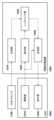
先ず、本実施形態に係るシステムの構成例について、図1のブロック図を用いて説明する。図1に示す如く、本実施形態に係るシステムは、RGB-Dセンサ1100と、HMD1000と、情報処理装置1200と、を有する。情報処理装置1200とHMD1000との間は、互いにデータ通信が可能なように接続されており、例えば、LANやインターネットなどのネットワークを介して接続されている。なお、情報処理装置1200とHMD1000との間の接続形態については特定の接続形態に限らない。例えば、無線であっても良いし有線であっても良い。また、HMD1000と情報処理装置1200とを一体化させて1つの装置としてもよい。また、情報処理装置1200とRGB-Dセンサ1100との間は、互いにデータ通信が可能なように接続されている。情報処理装置1200とRGB-Dセンサ1100との間の接続形態についても、特定の接続形態に限らない。First, a configuration example of a system according to this embodiment will be described with reference to the block diagram of FIG. 1. As shown in FIG. 1, the system according to this embodiment includes an RGB-
先ず、RGB-Dセンサ1100について説明する。RGB-Dセンサ1100は、現実空間中に配置され、その配置位置からの現実空間の色画像(例えばRGB画像)および距離画像を取得可能なセンサである。周知の如く、距離画像の各画素の画素値は該距離画像の撮像面からの奥行値を表していることから、該画素は現実空間(3次元空間)における1点(3次元点)に対応することになる。このように、距離画像は、該距離画像における各画素に対応する3次元点の集合(3次元点群)に対応していることから、以下では、距離画像を3次元点群と称する場合がある。First, the RGB-
なお、本実施形態では、現実空間の色画像および距離画像が取得できるのであれば、その方式は特定の方式に限らない。例えば、「RGBカメラ」と「Time of Flight方式あるいはアクティブステレオ方式、あるいは位相差検出方式などを利用した深度カメラ」とを組み合わせて、現実空間の色画像および距離画像を取得する方法を採用してもよい。また、ステレオのRGBカメラから距離画像を算出する方法や、単眼のRGBカメラから機械学習などによって距離画像を推定する方法を採用してもよい。In this embodiment, the method is not limited to a specific method as long as a color image and a distance image of the real space can be acquired. For example, a method may be adopted in which a color image and a distance image of the real space are acquired by combining an "RGB camera" with a "depth camera using a time-of-flight method, an active stereo method, or a phase difference detection method, etc." Also, a method may be adopted in which a distance image is calculated from a stereo RGB camera, or a method in which a distance image is estimated from a monocular RGB camera by machine learning, etc.
次に、HMD1000について説明する。HMD1000は、現実空間と仮想空間とを融合させた複合現実空間をユーザに提供するための頭部装着型表示装置の一例である。ユーザは自身の頭部にHMD1000を装着して該HMD1000に表示される画像を観察することで該複合現実空間を体感することができる。Next, we will explain the HMD 1000. The HMD 1000 is an example of a head-mounted display device that provides a user with a mixed reality space that combines real space and virtual space. A user can experience the mixed reality space by wearing the HMD 1000 on their head and observing the images displayed on the HMD 1000.
撮像部1010は、HMD1000を頭部に装着したユーザの視線方向と略一致する視線方向の現実空間の動画像を撮像し、該撮像した動画像の各フレームの色画像(現実空間の撮像画像)は順次、情報処理装置1200に対して出力される。撮像部1010は、単一の撮像センサによって単一画像を取得するものであっても良いし、左眼用及び右眼用の二つの撮像センサによってステレオ画像を取得するものであっても良い。The
表示部1020は、HMD1000を自身の頭部に装着したユーザの眼前に位置するようにHMD1000に取り付けられており、情報処理装置1200から送信される画像や文字を表示する。表示部1020は、ステレオ立体視のために、左眼と右眼に個別に表示を行えるよう、左眼用表示部と右眼用表示部とを有する構成であっても良いし、どちらか一方の眼のみに提示する構成でも良い。The
なお、HMD1000に加えて若しくは代えて撮像機能と表示機能とを有する装置を用いてもよく、そのような装置には、例えば、スマートフォンやタブレット端末装置が適用可能である。In addition to or instead of the HMD 1000, a device having imaging and display functions may be used, and examples of such devices include a smartphone and a tablet terminal device.
次に、情報処理装置1200について説明する。情報処理装置1200には、PC(パーソナルコンピュータ)、スマートフォン、タブレット端末装置などのコンピュータ装置を適用することができる。Next, the
生成部1210は、RGB-Dセンサ1100から得られる現実空間の距離画像および色画像に基づいて、仮想物体に対する環境マッピングを実施するために用いる環境マップを生成する。The
算出部1220は、撮像部1010から出力された現実空間の撮像画像から、世界座標系(現実空間中における1点を原点とし、該原点で互いに直交する3軸をそれぞれx軸、y軸、z軸とする座標系)における撮像部1010(視点)の位置姿勢を求める。本実施形態では、現実空間の撮像画像中に写っている特徴点に基づいて、Simultaneous Localization and Mapping(SLAM)の処理を実施することで、世界座標系における撮像部1010の位置姿勢を求める。なお、世界座標系における撮像部1010の位置姿勢を取得するための方法には様々な方法があり、特定の方法に限らない。例えば、撮像部1010に対する相対的な位置姿勢が既知のセンサをHMD1000に取り付け、該センサによる計測値を該相対的な位置姿勢に基づいて変換することで、世界座標系における撮像部1010の位置姿勢を求めるようにしても良い。また、モーションキャプチャシステムを利用して、世界座標系における撮像部1010の位置姿勢を求めてもよい。The
レンダリング部1230は、周囲環境の映り込みが再現された仮想物体を、生成部1210が生成した環境マップに基づいて生成し、該生成した仮想物体を算出部1220が求めた位置姿勢を有する視点から見た画像を、仮想物体画像として生成する。The
合成部1240は、撮像部1010から出力された現実空間の撮像画像と、レンダリング部1230によって生成された仮想物体画像と、を合成した合成画像を複合現実空間の画像として生成する。The
ここで、現実空間の撮像画像の画像領域における一部もしくは全部に仮想物体画像を合成(重畳)させる場合、現実物体と仮想物体との奥行きを考慮して、物体同士の隠蔽関係を整合させても良い。つまり、撮像画像における現実物体の画像領域において該現実物体よりも視点に近い仮想物体が重なっている部分領域については、仮想物体画像の重畳を許可する。一方、撮像画像における現実物体の画像領域において該現実物体よりも視点から遠い仮想物体が被っている部分領域については仮想物体画像の重畳を禁止する。Here, when a virtual object image is synthesized (superimposed) on a part or all of the image area of a captured image in real space, the occlusion relationship between the real object and the virtual object may be adjusted by taking into account the depth between the real object and the virtual object. In other words, the superimposition of a virtual object image is permitted for a partial area in the image area of a real object in the captured image where a virtual object closer to the viewpoint than the real object overlaps. On the other hand, the superimposition of a virtual object image is prohibited for a partial area in the image area of a real object in the captured image where a virtual object farther from the viewpoint than the real object overlaps.
そして合成部1240は、該生成した複合現実空間の画像をHMD1000(表示部1020)に対して出力する。これにより、HMD1000を自身の頭部に装着したユーザの眼前に、該複合現実空間の画像を提示することができる。The
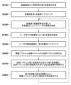
次に、視点の位置姿勢に応じた複合現実空間の画像を生成してHMD1000に出力するために情報処理装置1200が行う処理について、図9のフローチャートに従って説明する。なお、図9のフローチャートに従った処理は、1フレーム分の複合現実空間の画像を生成してHMD1000に出力するための処理である。よって、実際には、情報処理装置1200は、図9のフローチャートに従った処理を繰り返すことで、複数フレームの複合現実空間の画像を生成してHMD1000に出力する。Next, the process performed by the
ステップS901では、算出部1220は、撮像部1010から出力された現実空間の撮像画像を取得する。ステップS902では、算出部1220は、ステップS901で取得した撮像画像から、世界座標系における撮像部1010(視点)の位置姿勢を求める。In step S901, the
ステップS903では、生成部1210は、RGB-Dセンサ1100から得られる現実空間の距離画像および色画像に基づいて環境マップを生成する。そして、レンダリング部1230は、周囲環境の映り込みが再現された仮想物体を、生成部1210が生成した環境マップに基づいて生成し、該生成した仮想物体をステップS902で求めた位置姿勢を有する視点から見た画像を、仮想物体画像として生成する。In step S903, the
ステップS904では、合成部1240は、ステップS901で取得した現実空間の撮像画像と、ステップS903でレンダリング部1230によって生成された仮想物体画像と、を合成した合成画像を複合現実空間の画像として生成する。ステップS905では、合成部1240は、ステップS904で生成した複合現実空間の画像をHMD1000(表示部1020)に対して出力する。In step S904, the
次に、環境マップを生成する処理および該環境マップに基づいて「周囲環境の映り込みが再現された仮想物体の画像」を生成する処理について、図2のフローチャートに従って説明する。Next, the process of generating an environment map and the process of generating an "image of a virtual object in which the reflection of the surrounding environment is reproduced" based on the environment map will be explained with reference to the flowchart in Figure 2.
図2のフローチャートにおいてステップS2100およびステップS2200では、HMD1000を頭部に装着したユーザを含まない現実空間(該ユーザが複合現実空間を体感する空間の一例である部屋)の環境マップを生成する。よって、ステップS2100およびステップS2200は、該ユーザが該部屋に入る前に前処理として実行される。In the flowchart of FIG. 2, steps S2100 and S2200 generate an environmental map of a real space (a room, which is an example of a space in which the user experiences a mixed reality space) that does not include the user wearing the
ステップS2100では、生成部1210は、RGB-Dセンサ1100から出力された「HMD1000を頭部に装着したユーザを含まない現実空間(該ユーザが複合現実空間を体感する空間の一例である部屋)の距離画像および色画像」を取得する。ここで、一般的なRGB-Dセンサ1100の視野角では、全周囲の距離画像および色画像を一度に取得することは困難である。よって本実施形態では、RGB-Dセンサ1100を様々な方向に向けて全周囲(部屋全体)の撮像を行って、部屋全体の距離画像(部屋全体の3次元点群)および色画像(部屋の全周囲色画像)を取得する。そして生成部1210は、このような撮像により得られた部屋全体の距離画像が表す該部屋の形状(部屋全体の3次元点群によって規定される形状)に最もフィットする多面体(直方体、立方体など)を第1多面体として求める。In step S2100, the
なお、第1多面体を取得する方法は特定の方法に限らない。例えば、RGB-Dセンサ1100が取得する距離画像は部屋の一部の距離画像であってもよく、一部の距離画像から構成が困難な第1多面体の面については、他の面の位置姿勢や所定の値を用いて補完しても良い。また、事前に部屋の形状をメジャーなどの計測器で計測しておき、該計測により得られた計測値をもとに、第1多面体を構成してもよい。The method of acquiring the first polyhedron is not limited to a specific method. For example, the distance image acquired by the RGB-
このような撮像を行った後、本システムのオペレータはRGB-Dセンサ1100を、「HMD1000を装着して複合現実空間を体感するユーザが部屋内で行動すると推定される領域」を撮像可能な位置および姿勢に移動させる。該移動後のRGB-Dセンサ1100によって撮像された距離画像および色画像は生成部1210に出力される。生成部1210は、該距離画像が表す3次元点群が、部屋全体の距離画像が表す3次元点群のどの部分に最も一致するかを特定し、該特定した部分の3次元点群に基づいて、第1多面体に対するRGB-Dセンサ1100の相対的な位置姿勢(相対位置姿勢)を求める。また生成部1210は、第1多面体を規定する各頂点の位置を世界座標系における位置に変換する。この変換では、第1多面体を規定する各頂点の位置(RGB-Dセンサ1100の位置姿勢を基準とする座標系における位置)を、世界座標系におけるRGB-Dセンサ1100の位置姿勢と上記の相対位置姿勢とに基づいて変換する処理が行われる。世界座標系におけるRGB-Dセンサ1100の位置姿勢の取得方法は特定の取得方法に限らない。例えば、世界座標系における原点の位置にマーカを配置し、このマーカの色画像をRGB-Dセンサ1100で取得し、それを画像処理することによって自身の世界座標系における位置姿勢を推定しても良い。また、RGB-Dセンサ1100にモーションキャプチャなどの位置姿勢センサを取り付けて、自身の世界座標系における位置姿勢を計測しても良い。あるいは、RGB-Dセンサ1100にマーカを添付し、それを外部から撮影し、該撮影により得られる画像を画像処理することによって、RGB-Dセンサ1100の世界座標系における位置姿勢を推定しても良い。After capturing images in this way, the operator of the system moves the RGB-
次に、ステップS2200では、生成部1210は、ステップS2100でRGB-Dセンサ1100から取得した全周囲色画像を第1多面体にマッピングしたマッピング済み多面体を、第1環境マップとして生成する。このマッピングでは、第1多面体の各頂点と、全周囲色画像上の画素位置と、を対応付けている。これにより、第1多面体上の着目位置に対応する全周囲色画像上の画素位置を特定することができ、第1多面体上の着目位置に対応する色が、該着目位置に対応する全周囲色画像上の画素位置における画素値(色)であると特定することができる。Next, in step S2200, the
次に、ステップS2300~ステップS2500では、HMD1000を頭部に装着したユーザを含む現実空間(該ユーザが複合現実空間を体感する空間の一例である部屋)の環境マップを生成する。ステップS2300~ステップS2500の処理は、仮想物体画像を生成する各フレームについて行ってもよいし、所定の時間間隔で行ってもよい。Next, in steps S2300 to S2500, an environmental map of the real space (a room, which is an example of a space in which the user experiences a mixed reality space) including the user wearing the
ステップS2300では生成部1210は、RGB-Dセンサ1100から出力された距離画像および色画像を取得する。そして生成部1210は、該取得した距離画像および色画像の両方若しくは一方を用いた背景差分によって、該色画像におけるユーザの画像領域および該距離画像における該ユーザの領域を特定する。例えば、事前にユーザを含まない現実空間の画像を背景情報として一度取得しておく。そして、その後、ユーザが存在する現実空間の画像と背景情報との差分から、該画像におけるユーザの画像領域を抽出する。この「画像」を色画像として上記の処理を行えば、色画像におけるユーザの画像領域を特定することができ、「画像」を距離画像として上記の処理を行えば、距離画像におけるユーザの画像領域を特定することができる。In step S2300, the
ステップS2400では、生成部1210は、RGB-Dセンサ1100からユーザまでの距離に基づいて、第2多面体を設定する。例えば、生成部1210は、ステップS2300で特定した「距離画像におけるユーザの画像領域」を構成する各画素の画素値のうち最も小さい画素値(ユーザとRGB-Dセンサ1100との間の最小距離)を距離dとして特定する。そして生成部1210は、RGB-Dセンサ1100の世界座標系における位置を中心とし、一辺が2dの立方体を第2多面体として設定する。In step S2400, the
なお、距離dに適用するものは、上記の例に限らず、例えば、ステップS2300で特定した「距離画像におけるユーザの画像領域」を構成する各画素の画素値の平均値を距離dとしてもよい。また、「距離画像におけるユーザの画像領域」に対応する3次元点群の領域の一部をセグメンテーションし、このセグメンテーションされた一部の領域の重心(該領域の3次元点群の位置から求める)までの距離であっても良い。また、第2多面体は立方体に限らず、例えば、RGB-Dセンサ1100の世界座標系における位置を中心とし、「距離画像におけるユーザの画像領域」に対応する3次元点群の一部若しくは全部を含む多面体であってもよい。Note that the distance d is not limited to the above examples, and may be, for example, the average pixel value of each pixel constituting the "user's image area in the distance image" identified in step S2300. Alternatively, a part of the area of the three-dimensional point cloud corresponding to the "user's image area in the distance image" may be segmented, and the distance to the center of gravity of this segmented part of the area (determined from the position of the three-dimensional point cloud of the area) may be used. Furthermore, the second polyhedron is not limited to a cube, and may be, for example, a polyhedron centered on the position of the RGB-
ステップS2500では、生成部1210は、第2多面体において、「距離画像におけるユーザの画像領域」に対応する領域Rに、「色画像におけるユーザの画像領域」をマッピングしたマッピング済み多面体を、第2環境マップとして生成する。第2多面体において領域Rを除く他の領域には、「適当な値」を有する画素を有する画像をマッピングする。「適当な値」には、例えば、色画像がαチャンネルを有さない場合は、予め定義されたブランクの値を用いてもよいし、色画像がαチャンネルを有する場合は、α値「0」を用いてもよい。ユーザの画像領域は、環境マップの画像の一部にしか過ぎないため、メモリアクセスの処理時間を省くために画像領域のみを書き換える工夫などを適宜行っても良い。In step S2500, the
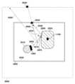
ここで、第1環境マップ、第2環境マップ、HMD1000を自身の頭部に装着したユーザ、RGB-Dセンサ1100、を俯瞰した様子を図3に示す。図3では、部屋3000全体の3次元点群に最もフィットする多面体3030が第1多面体として求められており、該多面体3030には部屋3000全体の全周囲色画像がマッピングされており、これが第1環境マップとなる。また、図3では、RGB-Dセンサ1100の位置を中心とし且つユーザ3010とRGB-Dセンサ1100との間の最小距離dの2倍の距離を一辺とする多面体3040が設定されている。多面体3040においてユーザの画像領域に対応する領域Rには、色画像における該画像領域がマッピングされており、これが第2環境マップとなる。また、ユーザ3010の頭部にはHMD1000が装着されている。Here, FIG. 3 shows an overhead view of the first environment map, the second environment map, the user wearing the
次に、ステップS2600~S2800では、第1環境マップおよび第2環境マップを用いて、周囲の現実空間の映り込みを反映させた仮想物体の画像(仮想物体画像)を生成する。ステップS2600~ステップS2800の処理は、仮想物体画像を生成する各フレームについて行う。Next, in steps S2600 to S2800, the first and second environment maps are used to generate an image of a virtual object (virtual object image) that reflects the surrounding real space. The processing in steps S2600 to S2800 is performed for each frame for which a virtual object image is generated.
ステップS2600では、レンダリング部1230は先ず、仮想物体を生成して配置する。そしてレンダリング部1230は、視点の位置から、仮想物体画像の各画素(着目画素)に対応する仮想空間中の位置への方向ベクトルを視線ベクトルとして求める。そしてレンダリング部1230は、それぞれの視線ベクトルについて、仮想物体において該視線ベクトルとの交点位置(仮想物体上の位置)を求め、該交点位置における該視線ベクトルの反射ベクトルを求める。仮想物体は、該仮想物体を規定する規定データ(仮想物体がポリゴンで構成される場合は、該ポリゴンの頂点の位置データ、該ポリゴンの法線データ、該ポリゴンの材質を表すデータ等を含む)を用いて構成される。仮想物体において視線ベクトルとの交点位置が特定されると、該交点位置における法線ベクトルは上記の規定データから取得することができるので、該視線ベクトルおよび該法線ベクトルから周知の計算方法により、対応する反射ベクトルを求めることができる。In step S2600, the
図3の例では、仮想物体3020において視線ベクトル3050との交点位置3060を求め、該交点位置3060における法線ベクトル3070と、該視線ベクトル3050と、から該視線ベクトル3050に対応する反射ベクトル3080を求める。図3に示す如く、反射ベクトル3080は、多面体3030と交差するサイズを有するものとする。In the example of FIG. 3, an
ステップS2700では、レンダリング部1230は、ステップS2600で求めた反射ベクトルごとに次のような処理を行う。つまりレンダリング部1230は、第1環境マップにおいて反射ベクトルとの交点位置を求め、該第1環境マップにおいて該交点位置における画素値(色)を第1色情報として特定する。図3の例では、第1環境マップである多面体3030において反射ベクトル3080との交点位置3100を求め、該交点位置3100における第1環境マップの画素値(色)を第1色情報として特定する。またレンダリング部1230は、第2環境マップにおいて反射ベクトルとの交点位置を求め、該第2環境マップにおいて該交点位置における画素値(色)を第2色情報として特定する。図3の例では、第2環境マップである多面体3040において反射ベクトル3080との交点位置3090を求め、該交点位置3090における第2環境マップの画素値(色)を第2色情報として特定する。In step S2700, the
ステップS2800では、レンダリング部1230は、反射ベクトルごとに次のような処理を行うことで、仮想物体画像における各画素の画素値(色)を確定する。レンダリング部1230は、着目反射ベクトルについてステップS2700で特定した第2色情報が「適用な値」ではない場合(第2環境マップにおいて着目反射ベクトルとの交点位置が、該第2環境マップにマッピングされているユーザの画像領域内である場合)には、着目反射ベクトルに対応する仮想物体画像の画素の画素値を第2色情報に基づいて決定する。一方、レンダリング部1230は、着目反射ベクトルについてステップS2700で特定した第2色情報が「適用な値」である場合(第2環境マップにおいて着目反射ベクトルとの交点位置が、該第2環境マップにマッピングされているユーザの画像領域外である場合)には、着目反射ベクトルに対応する仮想物体画像の画素の画素値を第1色情報に基づいて決定する。画素の画素値を第1色情報に基づいて決定する場合であっても第2色情報に基づいて決定する場合であっても、該画素に対応する仮想物体の面のマテリアル情報や環境光などを勘案して、最終的な画素値を決定する。In step S2800, the
このような処理をそれぞれの視線ベクトルに対応する反射ベクトルについて行うことで、視点から見た仮想物体の画像(仮想物体画像)における各画素の画素値(色)を決定することができる。By performing this process on the reflection vectors corresponding to each line of sight vector, the pixel value (color) of each pixel in the image of the virtual object seen from the viewpoint (virtual object image) can be determined.
[第2の実施形態]
本実施形態を含む以下の各実施形態では、第1の実施形態との差分について説明し、以下で特に触れない限りは第1の実施形態と同様であるものとする。一般的な環境マッピングでは、環境マップに利用する立方体や球体などの多面体に対して、映り込みが発生する仮想物体を十分に大きく設定し、またユーザの視線ベクトルと仮想物体との交点が環境マップの多面体の中心に存在するものと仮定する。これにより、交点での反射ベクトルから、環境マップにおけるどの画素の色を交点における映り込みの色としてサンプリングするかを簡易な計算で求めることができる。 Second Embodiment
In the following embodiments including this embodiment, the differences from the first embodiment will be described, and unless otherwise specified below, it is assumed that the embodiments are the same as the first embodiment. In general environment mapping, a virtual object that generates a reflection is set to be sufficiently large relative to a polyhedron such as a cube or sphere used in the environment map, and it is assumed that the intersection point between the user's line of sight vector and the virtual object exists at the center of the polyhedron in the environment map. This makes it possible to determine by simple calculation which pixel color in the environment map should be sampled as the reflection color at the intersection point, based on the reflection vector at the intersection point.
本実施形態では、第1の実施形態のように、現実物体の形状や位置に応じて、環境マップに利用する多面体自体の形状や大きさ、位置を変化させるのではなく、反射ベクトルを補正する。これにより、既存の一般的な環境マッピングの仕組みを活用しつつ、映り込み位置の不正確さを低減する。In this embodiment, unlike the first embodiment, the shape, size, and position of the polyhedron used in the environment map are not changed according to the shape and position of the real object, but the reflection vector is corrected. This reduces inaccuracies in the reflection position while utilizing the existing general environment mapping mechanism.
環境マップを生成する処理および該環境マップに基づいて「周囲環境の映り込みが再現された仮想物体の画像」を生成する処理について、図4のフローチャートに従って説明する。The process of generating an environment map and the process of generating an "image of a virtual object in which the surrounding environment is reproduced" based on the environment map will be explained with reference to the flowchart in Figure 4.
図4のフローチャートにおいてステップS4010~S4020では、HMD1000を頭部に装着したユーザを含まない現実空間(該ユーザが複合現実空間を体感する空間の一例である部屋)の環境マップを生成する。よって、ステップS4010~S4020は、該ユーザが該部屋に入る前に前処理として実行される。In the flowchart of FIG. 4, steps S4010 to S4020 generate an environmental map of a real space (a room, which is an example of a space in which the user experiences a mixed reality space) that does not include the user wearing the
ステップS4010では、生成部1210は、RGB-Dセンサ1100から出力された「HMD1000を頭部に装着したユーザを含まない現実空間(該ユーザが複合現実空間を体感する空間の一例である部屋)の距離画像および色画像」を取得する。本実施形態では、RGB-Dセンサ1100を部屋の中央に配置して様々な方向に向けて全周囲(部屋全体)の撮像を行って、部屋全体の距離画像(部屋全体の3次元点群)および色画像(部屋の全周囲色画像)を取得する。そして生成部1210は、部屋に対して十分に大きいサイズの多面体に該全周囲色画像をマッピングすることで第1環境マップを生成する。つまり生成部1210は、全周囲色画像がこの多面体に貼付されていると想定し、該多面体の頂点と全周囲色画像の座標とを対応付ける。ステップS4020では、生成部1210は、上記のステップS2100と同様の処理を行うことで、第1多面体を求める。In step S4010, the
このような撮像を行った後、第1の実施形態と同様、本システムのオペレータはRGB-Dセンサ1100を、「HMD1000を装着して複合現実空間を体感するユーザが部屋内で行動すると推定される領域」を撮像可能な位置および姿勢に移動させる。After capturing such images, as in the first embodiment, the operator of this system moves the RGB-
次に、ステップS4030~ステップS4050では、HMD1000を頭部に装着したユーザを含む現実空間(該ユーザが複合現実空間を体感する空間の一例である部屋)の環境マップを生成する。ステップS4030~ステップS4050の処理は、仮想物体画像を生成する各フレームについて行ってもよいし、所定の時間間隔で行ってもよい。Next, in steps S4030 to S4050, an environmental map of a real space (a room, which is an example of a space in which the user experiences a mixed reality space) including a user wearing the
ステップS4030では、生成部1210は、第1の実施形態と同様にして、色画像におけるユーザの画像領域および該距離画像における該ユーザの領域を特定する。In step S4030, the
ステップS4040では、生成部1210は、部屋に対して十分に大きいサイズの多面体にステップS4030で色画像から特定したユーザの画像領域をマッピングすることで第2環境マップを生成する。第2環境マップを立方体とすると、その立方体上のどの位置にユーザの画像領域を貼付するかの対応付けが整合的に行われる必要がある。これについては、世界座標系におけるRGB-Dセンサ1100の向きが規定されていれば、色画像座標が、環境マップ上のどこに位置づくかを一意に決定することができる。なお、多面体においてユーザの画像領域をマッピングしていない領域には、第1の実施形態と同様に、「適当な値」を有する画素を有する画像をマッピングする。ユーザの画像領域は、環境マップの画像の一部にしか過ぎないため、メモリアクセスの処理時間を省くために画像領域のみを書き換える工夫などを適宜行っても良い。ステップS4050では、生成部1210は、上記のステップS2400と同様の処理を行うことで、第2多面体を設定する。In step S4040, the
ここで、第1多面体、第2多面体、第1環境マップ、第2環境マップ、HMD1000を自身の頭部に装着したユーザ、RGB-Dセンサ1100、を俯瞰した様子を図5,6に示す。図5,6において図3に示した要素と同じ要素については同じ参照番号を付しており、該要素に係る説明は省略する。Here, Figs. 5 and 6 show an overhead view of the first polyhedron, the second polyhedron, the first environmental map, the second environmental map, the user wearing the
図5では、部屋3000よりも十分に大きいサイズを有する多面体5000には部屋3000全体の全周囲色画像がマッピングされており、これが第1環境マップとなる。図6では、部屋3000よりも十分に大きいサイズを有する多面体6000にはステップS4030で色画像から特定したユーザの画像領域がマッピングされており、これが第2環境マップとなる。In FIG. 5, a
次に、ステップS4060~S4110では、第1環境マップおよび第2環境マップを用いて、周囲の現実空間の映り込みを反映させた仮想物体の画像(仮想物体画像)を生成する。ステップS4060~ステップS4110の処理は、仮想物体画像を生成する各フレームについて行う。Next, in steps S4060 to S4110, the first and second environment maps are used to generate an image of a virtual object (virtual object image) that reflects the surrounding real space. The processing in steps S4060 to S4110 is performed for each frame for which a virtual object image is generated.
ステップS4060でレンダリング部1230は第1の実施形態と同様に、仮想物体を生成して配置し、それぞれの視線ベクトルについて、仮想物体において該視線ベクトルとの交点位置(対応位置)を求め、該交点位置における該視線ベクトルの反射ベクトルを求める。図5や図6の例では、仮想物体3020において視線ベクトル3050との交点位置3060を求め、該交点位置3060における法線ベクトル3070と、該視線ベクトル3050と、から該視線ベクトル3050に対応する反射ベクトル5020を求める。なお、ステップS4060で求めた反射ベクトルは、後の処理で補正するため、「仮の反射ベクトル」と称する。In step S4060, the
一般的な環境マッピングにおいては、仮の反射ベクトルを利用して、環境マップから反射色をサンプリングする。しかしながら一般的な環境マップは、環境マップが仮想物体に対して十分に大きいことを想定しており、反射ベクトルは常に環境マップの中心から伸びている(図5のベクトル5050参照)と近似することで計算を簡略化している。したがって、本実施形態のように有限の大きさの背景、例えば部屋などの映り込みの場合は、映り込み位置がずれることがある。そこで、以下のステップS4070~S4090の処理によって、この仮の反射ベクトルを補正して、映り込み位置のずれを補正する。以下では、図5,6を例にとり説明する。また、以下の処理は、それぞれの視線ベクトルについて求めた仮の反射ベクトルについて行う。In typical environment mapping, a provisional reflection vector is used to sample the reflected color from the environment map. However, typical environment maps assume that the environment map is sufficiently large compared to the virtual object, and the calculation is simplified by approximating that the reflection vector always extends from the center of the environment map (see
ステップS4070では、レンダリング部1230は、仮の反射ベクトル5020と第1多面体3030との交点位置5030(第1交点)を求めるとともに、仮の反射ベクトル5020と第2多面体3040との交点位置6020(第2の交点)を求める。In step S4070, the
ステップS4080では、レンダリング部1230は、第1環境マップである多面体5000において仮の反射ベクトル5020を補正した補正反射ベクトル5060を求める。一般的な環境マッピングの仕組みを活用するには、反射ベクトルが多面体5000の中心位置5010より伸びているという前提を壊さないことである。そこで、図5に示す如く、レンダリング部1230は、多面体5000の中心位置5010から交点位置3060に伸びるベクトル5070を求める。そしてレンダリング部1230は、中心位置5010を始点とし且つ「ベクトル5070と反射ベクトル5020(交点位置3060を始点とし、交点位置5030を終点とするベクトル)との合成ベクトル」を、補正反射ベクトル5060として求める。図5に示す如く、補正反射ベクトル5060は第1環境マップである多面体5000と交差するサイズを有する。In step S4080, the
ステップS4090では、レンダリング部1230は、第2環境マップである多面体6000において仮の反射ベクトル5020を補正した補正反射ベクトル6040を求める。つまり、図6に示す如く、レンダリング部1230は、多面体6000の中心位置から交点位置3060に伸びるベクトル6030を求める。そしてレンダリング部1230は、該中心位置を始点とし且つ「ベクトル6030と反射ベクトル5020(交点位置3060を始点とし、交点位置6020を終点とするベクトル)との合成ベクトル」を、補正反射ベクトル6040として求める。図6に示す如く、補正反射ベクトル6040は第2環境マップである多面体6000と交差するサイズを有する。In step S4090, the
ステップS4100では、レンダリング部1230は、第1環境マップである多面体5000において補正反射ベクトル5060との交点位置5040を求め、該多面体5000において該交点位置5040における画素値(色)を第1色情報として特定する。またレンダリング部1230は、第2環境マップである多面体6000において補正反射ベクトル6040との交点位置6050を求め、該多面体6000において該交点位置6050における画素値(色)を第2色情報として特定する。反射ベクトルが環境マップの中心から伸びている場合、環境マップにおいて色情報を取得する点は反射ベクトルの向きだけで決定することができる。In step S4100, the
ステップS4110では、レンダリング部1230は、着目補正反射ベクトルについてステップS4100で特定した第2色情報が「適当な値」ではない場合には、着目補正反射ベクトルに対応する仮想物体画像の画素の画素値を第2色情報に基づいて決定する。一方、レンダリング部1230は、着目補正反射ベクトルについてステップS4100で特定した第2色情報が「適当な値」である場合には、着目補正反射ベクトルに対応する仮想物体画像の画素の画素値を第1色情報に基づいて決定する。In step S4110, if the second color information identified in step S4100 for the focus-corrected reflection vector is not an "appropriate value," the
[第3の実施形態]
第1,2の実施形態では、RGB-Dセンサを用いて、環境マップの色画像を取得する取得デバイス(つまり該RGB-Dセンサ)から現実物体までの距離を直接的に計測している。しかし、環境マップの色画像を取得する取得デバイスと現実物体までの距離を計測することができれば、取得デバイスとして利用可能なデバイスはRGB-Dセンサに限らない。たとえば、色画像の取得デバイスとして広角カメラを用いてもよい。広角カメラは一般にRGB-Dセンサよりも入手性が高く、視野角も広いため、より簡便にシステムを構築・運用できると考えられる。本実施形態では、HMDの撮像部には複数のカメラもしくは深度センサが搭載されており、HMDからの深度情報を取得することで、環境マップの色画像を取得する広角カメラと現実物体までの距離情報を取得する場合について説明する。 [Third embodiment]
In the first and second embodiments, the RGB-D sensor is used to directly measure the distance from the acquisition device (i.e., the RGB-D sensor) that acquires the color image of the environment map to the real object. However, as long as the distance between the acquisition device that acquires the color image of the environment map and the real object can be measured, the device that can be used as the acquisition device is not limited to the RGB-D sensor. For example, a wide-angle camera may be used as the acquisition device for the color image. Since the wide-angle camera is generally more readily available than the RGB-D sensor and has a wider viewing angle, it is considered that the system can be constructed and operated more easily. In this embodiment, the imaging unit of the HMD is equipped with multiple cameras or depth sensors, and a case will be described in which distance information between the wide-angle camera that acquires the color image of the environment map and the real object is acquired by acquiring depth information from the HMD.
本実施形態に係るシステムの構成例について、図7のブロック図を用いて説明する。本実施形態に係るシステムでは、RGB-Dセンサ1100の代わりに広角カメラ7000を有する。広角カメラ7000は、HMD7050や情報処理装置1200の外部装置として設けられ、ユーザが複合現実空間を体感する空間全体を撮像する。An example of the configuration of a system according to this embodiment will be described with reference to the block diagram in FIG. 7. In the system according to this embodiment, a wide-
本実施形態に係るHMD7050が有する撮像部7010は、該HMD7050を自身の頭部に装着したユーザの視線と略一致する視線方向の現実空間のステレオ画像を撮像するステレオカメラとして機能する。なお、撮像部7010により撮像されるステレオ画像は、仮想物体画像と合成するために利用されるとともに、各画素が奥行値を有する距離画像(深度情報)を生成するためにも利用される。よって、撮像部7010は、仮想物体画像と合成するための色画像と、距離画像を生成するために必要な情報と、を取得できれば、ステレオカメラ以外の装置で構成されてもよい。The
本実施形態に係る情報処理装置1200が有する生成部7020は、撮像部7010からのステレオ画像から、「各画素が撮像部7010の撮像面からの奥行値を有する距離画像」を生成する。距離画像の生成方法は特定の生成方法に限らない。例えば、ステレオ画像からセミグローバルマッチング法により視差画像を算出し、ステレオ画像を取得した二つのカメラの相対的な位置関係から距離画像を生成する。なお、視差を得る方法は上記の方法に限らず、例えば、ステレオ画像で対応する特徴点やエッジから視差を得ても良いし、機械学習の推論によって視差を得ても良い。The
本実施形態に係る情報処理装置1200が有する算出部7030は、撮像部7010によるステレオ画像から第1の実施形態で説明した方法により、世界座標系における撮像部7010の位置姿勢を求める。そして算出部7030は、生成部7020が生成した距離画像中のユーザの領域を構成する各画素の奥行値(該画素に対応する3次元点の座標)を、世界座標系における撮像部7010の位置姿勢を用いて、世界座標系における3次元点の位置に変換する。そして算出部7030は、世界座標系における3次元点の位置の重心位置を、世界座標系におけるユーザの位置として求める。そして算出部7030は、前記、世界座標系におけるユーザの位置と世界座標における広角カメラ7000の位置姿勢からユーザと広角カメラ7000との間の相対的な位置姿勢(相対位置姿勢)を求める。なお広角カメラ7000の世界座標系における位置姿勢は、事前にメジャーで計測した値を利用しても良いし、広角カメラ7000にモーションキャプチャなどの位置姿勢センサを取り付けて計測しても良い。あるいは、広角カメラ7000にマーカを添付し、それを外部から撮影、画像処理をすることによって位置姿勢を推定しても良い。The
なお、複合現実感を体験する空間において、事前には何も物体が存在しない領域を指定しておくことで、体験中にこの領域に物体を検出した場合、その物体は移動体とみなすことができる。複合現実感においては、HMDを装着したユーザ自身の頭部や手などの身体が仮想物体へ映り込むことによって、現実空間と仮想空間の融合感がより高まると考えられる。そこで、算出部7030では、頭部や手といった特定の現実物体に特化して位置を算出しても良い。頭部位置は、撮像部に対して所定の相対位置に頭部が存在するとみなすことができる。また手の位置については、例えば、手の色を自身に登録しておき、色画像において手の色を有する画像領域を特定し、距離画像において該画像領域に対応する3次元点群の世界座標系における位置の重心位置を手の位置として利用することができる。In addition, by specifying an area in advance in which no objects exist in the space in which mixed reality is experienced, if an object is detected in this area during the experience, the object can be regarded as a moving object. In mixed reality, the head, hands, and other parts of the user's body wearing the HMD are reflected in the virtual object, which is thought to enhance the sense of fusion between the real space and the virtual space. Therefore, the
生成部7040は、第1環境マップおよび第2環境マップを生成する。第1環境マップおよび第2環境マップの生成方法は、第1の実施形態で説明した生成方法であってもよいし、第2の実施形態で説明した生成方法であってもよい。The
なお、本実施形態では、第1多面体に色画像をマッピングすることで第1環境マップを生成する場合、次のような処理を行う。すなわち、HMD7050の向きを動かすことで部屋全体の距離画像を取得し、該取得した距離画像から、部屋全体の3次元点群に最もフィットする多面体を第1多面体として取得する。そして、該第1多面体に広角カメラ7000による撮像画像をマッピングすることで第1環境マップを生成する。In this embodiment, when generating the first environment map by mapping a color image onto the first polyhedron, the following processing is performed. That is, a distance image of the entire room is acquired by moving the orientation of the
また、本実施形態では、第2多面体にユーザの画像領域をマッピングすることで第2環境マップを生成する場合には、次のような処理を行う。すなわち、世界座標系におけるユーザの位置と上記の相対位置姿勢とを用いて世界座標系における広角カメラ7000の位置を求める。そして、上記の相対位置姿勢から得られる「ユーザと広角カメラ7000との間の距離」を距離dとして求める。そして、世界座標系における広角カメラ7000の位置を中心とし、一辺が2dの立方体を第2多面体として設定する。なお、上記のように算出部7030が頭部や手といった特定現実物体に特化して位置を算出した場合、この値を利用する。そして、第2多面体に、広角カメラ7000による撮像画像においてユーザの画像領域を対応する領域にマッピングし、そのほかの領域には「適用な値」を有する画素の画像をマッピングすることで、第2環境マップを生成する。In addition, in this embodiment, when the second environment map is generated by mapping the user's image area on the second polyhedron, the following processing is performed. That is, the position of the wide-
[第4の実施形態]
上記の各実施形態では、HMDはビデオシースルー型のHMDであるものとして説明したが、光学シースルー方式のHMDであってもよい。後者の場合、合成部1240は、仮想物体画像をHMDの表示部に出力することになる。 [Fourth embodiment]
In the above embodiments, the HMD is described as a video see-through type HMD, but it may be an optical see-through type HMD. In the latter case, the
また、上記の各実施形態では、移動体は、HMDを頭部に装着したユーザであるものとして説明したが、該ユーザに加えて若しくは代えて他の物体を移動体としてもよい。また、移動体は単数であってもよいし、複数であってもよい。なお、「移動体」とは、常に動く物体に限らず、定期的もしくは不定期的に移動する物体であればよい。In addition, in each of the above embodiments, the moving body has been described as a user wearing an HMD on his/her head, but other objects may be used as the moving body in addition to or instead of the user. The moving body may be singular or multiple. Note that a "moving body" is not limited to an object that is constantly moving, but may be an object that moves periodically or irregularly.
また、第1の環境マップは、背景用の色画像をマッピングした多面体の一例であり、ユーザが複合現実空間を体感する空間において背景となる場所の色画像をマッピングした多面体であれば、如何なる多面体であってもよい。The first environment map is an example of a polyhedron onto which a background color image is mapped, and may be any polyhedron onto which a color image of a location that serves as the background in the space in which the user experiences the mixed reality space is mapped.
また、図1,7に示した情報処理装置1200が有するものとして示した各機能部はハードウェアで実装してもよいし、ソフトウェア(コンピュータプログラム)で実装してもよい。後者の場合、このコンピュータプログラムを実行可能なコンピュータ装置は情報処理装置1200に適用することができる。情報処理装置1200に適用可能なコンピュータ装置のハードウェア構成例について、図8のブロック図を用いて説明する。Furthermore, each functional unit shown as possessed by the
CPU8200は、RAM8400やROM8300に格納されているコンピュータプログラムやデータを用いて各種の処理を実行する。これによりCPU8200は、コンピュータ装置全体の動作制御を行うとともに、情報処理装置1200が行うものとして上述した各処理を実行もしくは制御する。The
ROM8300には、コンピュータ装置の設定データや起動プログラムなどが格納されている。RAM8400は、外部記憶装置8450やROM8300からロードされたコンピュータプログラムやデータを格納するためのエリアを有する。さらにRAM8400は、入力I/F8500を介して外部装置(RGB-Dセンサ1100、撮像部1010、撮像部7010、広角カメラ7000など)から受信した各種のデータを格納するためのエリアを有する。さらにRAM8400は、CPU8200が各種の処理を実行する際に用いるワークエリアを有する。このようにRAM8400は各種のエリアを適宜提供することができる。The
外部記憶装置8450は、ハードディスクドライブ装置などの大容量情報記憶装置である。外部記憶装置8450には、OS(オペレーティングシステム)や、情報処理装置1200が行うものとして上述した各処理をCPU8200に実行もしくは制御させるためのコンピュータプログラムやデータが保存されている。The
外部記憶装置8450に保存されているコンピュータプログラムには、図1,7に示した情報処理装置1200が有するものとして示した各機能部の機能をCPU8200に実行もしくは制御させるためのコンピュープログラムが含まれている。The computer programs stored in the
外部記憶装置8450に保存されているデータには、仮想物体に関連する上記の規定データ、仮想空間に関連するデータ(仮想空間中に配置される光源を規定するデータなど)、仮想物体画像と共に表示される画像や文字のデータが含まれている。The data stored in the
外部記憶装置8450に保存されているコンピュータプログラムやデータは、CPU8200による制御に従って適宜RAM8400にロードされ、CPU8200による処理対象となる。Computer programs and data stored in the
入力I/F8500は、外部装置(HMD1000、RGB-Dセンサ1100、HMD7050、広角カメラ7000など)からのデータ入力を行うための通信インターフェースである。出力I/F8600は、外部装置(HMD1000、HMD7050など)に対するデータ出力を行うための通信インターフェースである。The input I/
CPU8200、ROM8300、RAM8400、外部記憶装置8450、入力I/F8500、出力I/F8600は何れも、システムバス8100に接続されている。なお、情報処理装置1200に適用可能なコンピュータ装置のハードウェア構成は、図8に示した構成に限らず、適宜変形/変更が可能である。The
なお、上記の説明において使用した数値、処理タイミング、処理順などは、具体的な説明を行うために一例として挙げたものであり、これらの数値、処理タイミング、処理順などに限定することを意図したものではない。Note that the numerical values, processing timing, processing order, etc. used in the above explanation are given as examples to provide a concrete explanation, and are not intended to be limiting.
また、以上説明した各実施形態の一部若しくは全部を適宜組み合わせて使用しても構わない。また、以上説明した各実施形態の一部若しくは全部を選択的に使用しても構わない。Furthermore, any or all of the embodiments described above may be used in appropriate combination.Furthermore, any or all of the embodiments described above may be used selectively.
(その他の実施形態)
本発明は、上述の実施形態の1以上の機能を実現するプログラムを、ネットワーク又は記憶媒体を介してシステム又は装置に供給し、そのシステム又は装置のコンピュータにおける1つ以上のプロセッサがプログラムを読出し実行する処理でも実現可能である。また、1以上の機能を実現する回路(例えば、ASIC)によっても実現可能である。 Other Embodiments
The present invention can also be realized by a process in which a program for implementing one or more of the functions of the above-described embodiments is supplied to a system or device via a network or a storage medium, and one or more processors in a computer of the system or device read and execute the program. The present invention can also be realized by a circuit (e.g., ASIC) that implements one or more of the functions.
発明は上記実施形態に制限されるものではなく、発明の精神及び範囲から離脱することなく、様々な変更及び変形が可能である。従って、発明の範囲を公にするために請求項を添付する。The invention is not limited to the above-described embodiment, and various modifications and variations are possible without departing from the spirit and scope of the invention. Therefore, the following claims are appended to disclose the scope of the invention.
1000:HMD 1010:撮像部 1020:表示部 1100:RGB-Dセンサ 1200:情報処理装置 1210:生成部 1220:算出部 1230:レンダリング部 1240:合成部1000: HMD 1010: Imaging unit 1020: Display unit 1100: RGB-D sensor 1200: Information processing device 1210: Generation unit 1220: Calculation unit 1230: Rendering unit 1240: Synthesis unit
Claims (13)
Translated fromJapanese現実空間の色画像を取得するデバイスと移動体との間の距離に応じたサイズを有する多面体に、該デバイスが取得した該移動体の色画像をマッピングすることで得られるマッピング済み多面体を第2環境マップとして生成する第2生成手段と、
仮想物体の画像を生成する第3生成手段と
を備え、
前記第3生成手段は、前記仮想物体の画像の画素値を、前記第1環境マップと、前記第2環境マップと、に基づいて決定する
ことを特徴とする情報処理装置。 a first generating means for generating a polyhedron onto which a background color image is mapped as a first environment map;
a second generating means for generating, as a second environment map, a mapped polyhedron obtained by mapping a color image of the moving body acquired by a device that acquires a color image of the real space onto a polyhedron having a size corresponding to a distance between the moving body and the device;
and a third generating means for generating an image of a virtual object,
the third generating means determines a pixel value of the image of the virtual object based on the first environment map and the second environment map.
前記仮想物体の画像における着目画素に対応する前記仮想物体上の位置への視線ベクトルの、該位置における反射ベクトルを求める手段と、
前記第2環境マップにおいて前記反射ベクトルとの交点位置が、該第2環境マップにマッピングされている移動体の画像領域内であれば、前記第2環境マップの前記反射ベクトルとの交点位置における画素値に基づいて前記着目画素の画素値を決定し、前記第2環境マップにおいて前記反射ベクトルとの交点位置が、該第2環境マップにマッピングされている移動体の画像領域外であれば、前記第1環境マップの前記反射ベクトルとの交点位置における画素値に基づいて前記着目画素の画素値を決定する手段と
を備えることを特徴とする請求項1ないし3の何れか1項に記載の情報処理装置。 The third generating means is
means for calculating a reflection vector at a position on the virtual object corresponding to a pixel of interest in an image of the virtual object, of a line of sight vector to the position;
The information processing device according to any one of claims 1 to 3, further comprising: a means for determining a pixel value of the pixel of interest based on a pixel value at the intersection position with the reflection vector in the second environment map if the intersection position with the reflection vector in the second environment map is within an image area of a moving body mapped to the second environment map; and a means for determining a pixel value of the pixel of interest based on a pixel value at the intersection position with the reflection vector in the first environment map if the intersection position with the reflection vector in the second environment map is outside an image area of a moving body mapped to the second environment map.
移動体を含む現実空間の色画像をマッピングした多面体を第2環境マップとして生成する第2生成手段と、
仮想物体の画像を生成する第3生成手段と
を備え、
前記第3生成手段は、
前記仮想物体の画像における着目画素に対応する前記仮想物体上の対応位置への視線ベクトルの、該対応位置における反射ベクトルを求め、該反射ベクトルを前記第1環境マップおよび前記第2環境マップのそれぞれについて補正した補正反射ベクトルと、前記第1環境マップと、前記第2環境マップと、に基づいて、前記着目画素の画素値を決定する
ことを特徴とする情報処理装置。 a first generating means for generating a polyhedron onto which a background color image is mapped as a first environment map;
a second generating means for generating a polyhedron onto which a color image of a real space including a moving object is mapped as a second environment map;
and a third generating means for generating an image of a virtual object,
The third generating means is
an information processing apparatus comprising: a display unit that displays a pixel value of the target pixel based on a line of sight vector of the line of sight vector to a corresponding position on the virtual object corresponding to the pixel value of the target pixel in an image of the virtual object; and a display unit that displays a pixel value of the target pixel based on a corrected reflection vector obtained by correcting the reflection vector for each of the firstenvironment map and the second environment map, the corrected reflection vector being obtained by correcting the line of sight ...
前記反射ベクトルを、前記第1環境マップの中心位置から前記対応位置へのベクトルに基づいて補正した第1補正反射ベクトルを求める手段と、
前記反射ベクトルを、前記第2環境マップの中心位置から前記対応位置へのベクトルに基づいて補正した第2補正反射ベクトルを求める手段と、
前記第2環境マップにおいて前記第2補正反射ベクトルとの交点位置が、該第2環境マップにマッピングされている移動体の画像領域内であれば、前記第2環境マップの前記第2補正反射ベクトルとの交点位置における画素値に基づいて前記着目画素の画素値を決定し、前記第2環境マップにおいて前記第2補正反射ベクトルとの交点位置が、該第2環境マップにマッピングされている移動体の画像領域外であれば、前記第1環境マップの前記第1補正反射ベクトルとの交点位置における画素値に基づいて前記着目画素の画素値を決定する手段と
を備えることを特徴とする請求項5ないし7の何れか1項に記載の情報処理装置。 The third generating means is
a means for obtaining a first corrected reflection vector by correcting the reflection vector based on a vector from a center position of the first environment map to the corresponding position;
a means for obtaining a second corrected reflection vector by correcting the reflection vector based on a vector from a center position of the second environment map to the corresponding position;
8. The information processing device according to claim 5, further comprising: a means for determining a pixel value of the pixel of interest based on a pixel value at the intersection position with the second corrected reflection vector in the second environment map if the intersection position with the second corrected reflection vector in the second environment map is within an image area of the moving body mapped to the second environment map; and a means for determining a pixel value of the pixel of interest based on a pixel value at the intersection position with the first corrected reflection vector in the first environment map if the intersection position with the second corrected reflection vector in the second environment map is outside an image area of the moving body mapped to the second environment map.
前記仮想物体の画像を、頭部装着型表示装置によって撮像された現実空間の画像と合成して該頭部装着型表示装置に出力することを特徴とする請求項1ないし8の何れか1項に記載の情報処理装置。 The third generating means is
9. The information processing apparatus according to claim 1, wherein the image of the virtual object is synthesized with an image of real space captured by a head-mounted display device and output to the head-mounted display device.
前記情報処理装置の第1生成手段が、背景用の色画像をマッピングした多面体を第1環境マップとして生成する第1生成工程と、
前記情報処理装置の第2生成手段が、現実空間の色画像を取得するデバイスと移動体との間の距離に応じたサイズを有する多面体に、該デバイスが取得した該移動体の色画像をマッピングすることで得られるマッピング済み多面体を第2環境マップとして生成する第2生成工程と、
前記情報処理装置の第3生成手段が、仮想物体の画像を生成する第3生成工程と
を備え、
前記第3生成工程では、前記仮想物体の画像の画素値を、前記第1環境マップと、前記第2環境マップと、に基づいて決定する
ことを特徴とする情報処理方法。 An information processing method performed by an information processing device,
a first generation step in which a first generation means of the information processing device generates a polyhedron onto which a background color image is mapped as a first environment map;
a second generation step in which a second generation means of the information processing device generates, as a second environment map, a mapped polyhedron obtained by mapping a color image of the moving body acquired by a device that acquires a color image of real space onto a polyhedron having a size corresponding to a distance between the moving body and the device;
a third generation step in which a third generation means of the information processing device generates an image of a virtual object;
the third generating step determines pixel values of the image of the virtual object based on the first environment map and the second environment map.
前記情報処理装置の第1生成手段が、背景用の色画像をマッピングした多面体を第1環境マップとして生成する第1生成工程と、
前記情報処理装置の第2生成手段が、移動体を含む現実空間の色画像をマッピングした多面体を第2環境マップとして生成する第2生成工程と、
前記情報処理装置の第3生成手段が、仮想物体の画像を生成する第3生成工程と
を備え、
前記第3生成工程では、
前記仮想物体の画像における着目画素に対応する前記仮想物体上の対応位置への視線ベクトルの、該対応位置における反射ベクトルを求め、該反射ベクトルを前記第1環境マップおよび前記第2環境マップのそれぞれについて補正した補正反射ベクトルと、前記第1環境マップと、前記第2環境マップと、に基づいて、前記着目画素の画素値を決定する
ことを特徴とする情報処理方法。 An information processing method performed by an information processing device,
a first generation step in which a first generation means of the information processing device generates a polyhedron onto which a background color image is mapped as a first environment map;
a second generation step in which a second generation means of the information processing device generates, as a second environment map, a polyhedron onto which a color image of a real space including a moving object is mapped;
a third generation step in which a third generation means of the information processing device generates an image of a virtual object;
In the third generation step,
an information processing method comprising: determining a reflection vector at a corresponding position on the virtual object corresponding to a pixel of interest in an image of the virtual object, of a line of sight vector to the corresponding position, and determining a pixel value of the pixel of interest based on a corrected reflection vector obtained by correcting the reflection vector for each of the firstenvironment map and the second environment map, the first environment map, and the second environment map.
Priority Applications (1)
| Application Number | Priority Date | Filing Date | Title |
|---|---|---|---|
| JP2020056622AJP7465133B2 (en) | 2020-03-26 | 2020-03-26 | Information processing device and information processing method |
Applications Claiming Priority (1)
| Application Number | Priority Date | Filing Date | Title |
|---|---|---|---|
| JP2020056622AJP7465133B2 (en) | 2020-03-26 | 2020-03-26 | Information processing device and information processing method |
Publications (3)
| Publication Number | Publication Date |
|---|---|
| JP2021157458A JP2021157458A (en) | 2021-10-07 |
| JP2021157458A5 JP2021157458A5 (en) | 2023-03-29 |
| JP7465133B2true JP7465133B2 (en) | 2024-04-10 |
Family
ID=77917934
Family Applications (1)
| Application Number | Title | Priority Date | Filing Date |
|---|---|---|---|
| JP2020056622AActiveJP7465133B2 (en) | 2020-03-26 | 2020-03-26 | Information processing device and information processing method |
Country Status (1)
| Country | Link |
|---|---|
| JP (1) | JP7465133B2 (en) |
Citations (2)
| Publication number | Priority date | Publication date | Assignee | Title |
|---|---|---|---|---|
| JP2008033531A (en) | 2006-07-27 | 2008-02-14 | Canon Inc | Information processing method |
| JP2020535557A (en) | 2017-09-29 | 2020-12-03 | 株式会社ソニー・インタラクティブエンタテインメント | Modular Hierarchical Visual System for Autonomous Personal Companion |
- 2020
- 2020-03-26JPJP2020056622Apatent/JP7465133B2/enactiveActive
Patent Citations (2)
| Publication number | Priority date | Publication date | Assignee | Title |
|---|---|---|---|---|
| JP2008033531A (en) | 2006-07-27 | 2008-02-14 | Canon Inc | Information processing method |
| JP2020535557A (en) | 2017-09-29 | 2020-12-03 | 株式会社ソニー・インタラクティブエンタテインメント | Modular Hierarchical Visual System for Autonomous Personal Companion |
Also Published As
| Publication number | Publication date |
|---|---|
| JP2021157458A (en) | 2021-10-07 |
Similar Documents
| Publication | Publication Date | Title |
|---|---|---|
| US11928838B2 (en) | Calibration system and method to align a 3D virtual scene and a 3D real world for a stereoscopic head-mounted display | |
| CN107209950B (en) | Automatic generation of virtual material from real world material | |
| JP6687204B2 (en) | Projection image generation method and apparatus, and mapping method between image pixels and depth values | |
| JP4804256B2 (en) | Information processing method | |
| US20200027194A1 (en) | Mixed reality system with virtual content warping and method of generating virtual content using same | |
| KR102359978B1 (en) | Mixed reality system with multi-source virtual content synthesis and method for creating virtual content using same | |
| JP5818773B2 (en) | Image processing apparatus, image processing method, and program | |
| WO2018116790A1 (en) | Inconsistency detection system, mixed reality system, program, and inconsistency detection method | |
| JP4667111B2 (en) | Image processing apparatus and image processing method | |
| JP2020514908A (en) | Mixed reality system with color virtual content warping and method of generating virtual content using the same | |
| KR20180101496A (en) | Head-mounted display for virtual and mixed reality with inside-out location, user body and environment tracking | |
| JP2018511098A (en) | Mixed reality system | |
| JP2004062758A (en) | Information processing apparatus and method | |
| CN116309854B (en) | Method, device, equipment, system and storage medium for calibrating augmented reality equipment | |
| JP2010109783A (en) | Electronic camera | |
| CN110969706B (en) | Augmented reality device, image processing method, system and storage medium thereof | |
| JP2018106661A (en) | Inconsistency detection system, mixed reality system, program, and inconsistency detection method | |
| CN119301946A (en) | Image processing device, head mounted display device, control method of image processing device, control method of head mounted display device, and program | |
| JP2019133310A (en) | Image processing system and image processing program and image processing method | |
| JP7175715B2 (en) | Information processing device, information processing method and program | |
| JP6890524B2 (en) | Attitude control system | |
| JP7465133B2 (en) | Information processing device and information processing method | |
| US20230122185A1 (en) | Determining relative position and orientation of cameras using hardware | |
| JP4689344B2 (en) | Information processing method and information processing apparatus | |
| WO2018173205A1 (en) | Information processing system, method for controlling same, and program |
Legal Events
| Date | Code | Title | Description |
|---|---|---|---|
| RD01 | Notification of change of attorney | Free format text:JAPANESE INTERMEDIATE CODE: A7421 Effective date:20210103 | |
| A521 | Request for written amendment filed | Free format text:JAPANESE INTERMEDIATE CODE: A523 Effective date:20210113 | |
| A521 | Request for written amendment filed | Free format text:JAPANESE INTERMEDIATE CODE: A523 Effective date:20230320 | |
| A621 | Written request for application examination | Free format text:JAPANESE INTERMEDIATE CODE: A621 Effective date:20230320 | |
| A977 | Report on retrieval | Free format text:JAPANESE INTERMEDIATE CODE: A971007 Effective date:20240215 | |
| TRDD | Decision of grant or rejection written | ||
| A01 | Written decision to grant a patent or to grant a registration (utility model) | Free format text:JAPANESE INTERMEDIATE CODE: A01 Effective date:20240301 | |
| A61 | First payment of annual fees (during grant procedure) | Free format text:JAPANESE INTERMEDIATE CODE: A61 Effective date:20240329 | |
| R150 | Certificate of patent or registration of utility model | Ref document number:7465133 Country of ref document:JP Free format text:JAPANESE INTERMEDIATE CODE: R150 |