JP7463404B2 - Clamp-based lockout mechanism for right-angle surgical stapler - Google Patents
Clamp-based lockout mechanism for right-angle surgical staplerDownload PDFInfo
- Publication number
- JP7463404B2 JP7463404B2JP2021563287AJP2021563287AJP7463404B2JP 7463404 B2JP7463404 B2JP 7463404B2JP 2021563287 AJP2021563287 AJP 2021563287AJP 2021563287 AJP2021563287 AJP 2021563287AJP 7463404 B2JP7463404 B2JP 7463404B2
- Authority
- JP
- Japan
- Prior art keywords
- firing
- end effector
- closure
- tissue
- surgical stapler
- Prior art date
- Legal status (The legal status is an assumption and is not a legal conclusion. Google has not performed a legal analysis and makes no representation as to the accuracy of the status listed.)
- Active
Links
- 230000007246mechanismEffects0.000titleclaimsdescription116
- 238000010304firingMethods0.000claimsdescription280
- 239000012636effectorSubstances0.000claimsdescription182
- 230000004044responseEffects0.000claimsdescription32
- 230000005764inhibitory processEffects0.000claims1
- 238000000034methodMethods0.000description9
- 230000002401inhibitory effectEffects0.000description8
- 230000007704transitionEffects0.000description6
- 230000014509gene expressionEffects0.000description5
- 230000004048modificationEffects0.000description4
- 238000012986modificationMethods0.000description4
- 230000005855radiationEffects0.000description4
- 238000001356surgical procedureMethods0.000description4
- 238000004140cleaningMethods0.000description3
- 230000023597hemostasisEffects0.000description3
- 238000003780insertionMethods0.000description3
- 230000037431insertionEffects0.000description3
- 238000011282treatmentMethods0.000description3
- 230000006835compressionEffects0.000description2
- 238000007906compressionMethods0.000description2
- 230000008878couplingEffects0.000description2
- 238000010168coupling processMethods0.000description2
- 238000005859coupling reactionMethods0.000description2
- 229920001903high density polyethylenePolymers0.000description2
- 239000004700high-density polyethyleneSubstances0.000description2
- 230000003993interactionEffects0.000description2
- 230000036244malformationEffects0.000description2
- 239000000463materialSubstances0.000description2
- 241000894006BacteriaSpecies0.000description1
- IAYPIBMASNFSPL-UHFFFAOYSA-NEthylene oxideChemical compoundC1CO1IAYPIBMASNFSPL-UHFFFAOYSA-N0.000description1
- 239000004775TyvekSubstances0.000description1
- 229920000690TyvekPolymers0.000description1
- 230000006978adaptationEffects0.000description1
- 230000000712assemblyEffects0.000description1
- 238000000429assemblyMethods0.000description1
- 238000007681bariatric surgeryMethods0.000description1
- 230000000994depressogenic effectEffects0.000description1
- 238000010894electron beam technologyMethods0.000description1
- 230000001747exhibiting effectEffects0.000description1
- 208000014674injuryDiseases0.000description1
- 238000002324minimally invasive surgeryMethods0.000description1
- 230000035515penetrationEffects0.000description1
- 229920003023plasticPolymers0.000description1
- 239000004033plasticSubstances0.000description1
- 230000002028prematureEffects0.000description1
- 230000008707rearrangementEffects0.000description1
- 238000002271resectionMethods0.000description1
- 230000000630rising effectEffects0.000description1
- 230000035945sensitivityEffects0.000description1
- 230000001954sterilising effectEffects0.000description1
- 238000004659sterilization and disinfectionMethods0.000description1
- 210000000115thoracic cavityAnatomy0.000description1
- 230000008733traumaEffects0.000description1
- XLYOFNOQVPJJNP-UHFFFAOYSA-NwaterChemical compoundOXLYOFNOQVPJJNP-UHFFFAOYSA-N0.000description1
Images


Classifications
- A—HUMAN NECESSITIES
- A61—MEDICAL OR VETERINARY SCIENCE; HYGIENE
- A61B—DIAGNOSIS; SURGERY; IDENTIFICATION
- A61B17/00—Surgical instruments, devices or methods
- A61B17/068—Surgical staplers, e.g. containing multiple staples or clamps
- A61B17/072—Surgical staplers, e.g. containing multiple staples or clamps for applying a row of staples in a single action, e.g. the staples being applied simultaneously
- A—HUMAN NECESSITIES
- A61—MEDICAL OR VETERINARY SCIENCE; HYGIENE
- A61B—DIAGNOSIS; SURGERY; IDENTIFICATION
- A61B17/00—Surgical instruments, devices or methods
- A61B17/28—Surgical forceps
- A61B17/29—Forceps for use in minimally invasive surgery
- A61B17/2909—Handles
- A—HUMAN NECESSITIES
- A61—MEDICAL OR VETERINARY SCIENCE; HYGIENE
- A61B—DIAGNOSIS; SURGERY; IDENTIFICATION
- A61B17/00—Surgical instruments, devices or methods
- A61B17/10—Surgical instruments, devices or methods for applying or removing wound clamps, e.g. containing only one clamp or staple; Wound clamp magazines
- A61B17/105—Wound clamp magazines
- A—HUMAN NECESSITIES
- A61—MEDICAL OR VETERINARY SCIENCE; HYGIENE
- A61B—DIAGNOSIS; SURGERY; IDENTIFICATION
- A61B17/00—Surgical instruments, devices or methods
- A61B2017/0046—Surgical instruments, devices or methods with a releasable handle; with handle and operating part separable
- A—HUMAN NECESSITIES
- A61—MEDICAL OR VETERINARY SCIENCE; HYGIENE
- A61B—DIAGNOSIS; SURGERY; IDENTIFICATION
- A61B17/00—Surgical instruments, devices or methods
- A61B17/068—Surgical staplers, e.g. containing multiple staples or clamps
- A61B17/072—Surgical staplers, e.g. containing multiple staples or clamps for applying a row of staples in a single action, e.g. the staples being applied simultaneously
- A61B2017/07214—Stapler heads
- A61B2017/07221—Stapler heads curved
- A—HUMAN NECESSITIES
- A61—MEDICAL OR VETERINARY SCIENCE; HYGIENE
- A61B—DIAGNOSIS; SURGERY; IDENTIFICATION
- A61B17/00—Surgical instruments, devices or methods
- A61B17/068—Surgical staplers, e.g. containing multiple staples or clamps
- A61B17/072—Surgical staplers, e.g. containing multiple staples or clamps for applying a row of staples in a single action, e.g. the staples being applied simultaneously
- A61B2017/07214—Stapler heads
- A61B2017/0725—Stapler heads with settable gap between anvil and cartridge, e.g. for different staple heights at different shots
- A—HUMAN NECESSITIES
- A61—MEDICAL OR VETERINARY SCIENCE; HYGIENE
- A61B—DIAGNOSIS; SURGERY; IDENTIFICATION
- A61B17/00—Surgical instruments, devices or methods
- A61B17/068—Surgical staplers, e.g. containing multiple staples or clamps
- A61B17/072—Surgical staplers, e.g. containing multiple staples or clamps for applying a row of staples in a single action, e.g. the staples being applied simultaneously
- A61B2017/07214—Stapler heads
- A61B2017/07257—Stapler heads characterised by its anvil
- A—HUMAN NECESSITIES
- A61—MEDICAL OR VETERINARY SCIENCE; HYGIENE
- A61B—DIAGNOSIS; SURGERY; IDENTIFICATION
- A61B17/00—Surgical instruments, devices or methods
- A61B17/068—Surgical staplers, e.g. containing multiple staples or clamps
- A61B17/072—Surgical staplers, e.g. containing multiple staples or clamps for applying a row of staples in a single action, e.g. the staples being applied simultaneously
- A61B2017/07214—Stapler heads
- A61B2017/07271—Stapler heads characterised by its cartridge
- A—HUMAN NECESSITIES
- A61—MEDICAL OR VETERINARY SCIENCE; HYGIENE
- A61B—DIAGNOSIS; SURGERY; IDENTIFICATION
- A61B17/00—Surgical instruments, devices or methods
- A61B17/28—Surgical forceps
- A61B17/29—Forceps for use in minimally invasive surgery
- A61B17/2909—Handles
- A61B2017/2925—Pistol grips
- A—HUMAN NECESSITIES
- A61—MEDICAL OR VETERINARY SCIENCE; HYGIENE
- A61B—DIAGNOSIS; SURGERY; IDENTIFICATION
- A61B17/00—Surgical instruments, devices or methods
- A61B17/28—Surgical forceps
- A61B17/29—Forceps for use in minimally invasive surgery
- A61B2017/2946—Locking means
- A—HUMAN NECESSITIES
- A61—MEDICAL OR VETERINARY SCIENCE; HYGIENE
- A61B—DIAGNOSIS; SURGERY; IDENTIFICATION
- A61B90/00—Instruments, implements or accessories specially adapted for surgery or diagnosis and not covered by any of the groups A61B1/00 - A61B50/00, e.g. for luxation treatment or for protecting wound edges
- A61B90/03—Automatic limiting or abutting means, e.g. for safety
- A61B2090/033—Abutting means, stops, e.g. abutting on tissue or skin
- A61B2090/034—Abutting means, stops, e.g. abutting on tissue or skin abutting on parts of the device itself
- A—HUMAN NECESSITIES
- A61—MEDICAL OR VETERINARY SCIENCE; HYGIENE
- A61B—DIAGNOSIS; SURGERY; IDENTIFICATION
- A61B90/00—Instruments, implements or accessories specially adapted for surgery or diagnosis and not covered by any of the groups A61B1/00 - A61B50/00, e.g. for luxation treatment or for protecting wound edges
- A61B90/03—Automatic limiting or abutting means, e.g. for safety
- A61B2090/038—Automatic limiting or abutting means, e.g. for safety during shipment
- A—HUMAN NECESSITIES
- A61—MEDICAL OR VETERINARY SCIENCE; HYGIENE
- A61B—DIAGNOSIS; SURGERY; IDENTIFICATION
- A61B90/00—Instruments, implements or accessories specially adapted for surgery or diagnosis and not covered by any of the groups A61B1/00 - A61B50/00, e.g. for luxation treatment or for protecting wound edges
- A61B90/08—Accessories or related features not otherwise provided for
- A61B2090/0814—Preventing re-use
Landscapes
- Health & Medical Sciences (AREA)
- Life Sciences & Earth Sciences (AREA)
- Surgery (AREA)
- Heart & Thoracic Surgery (AREA)
- Engineering & Computer Science (AREA)
- Biomedical Technology (AREA)
- Nuclear Medicine, Radiotherapy & Molecular Imaging (AREA)
- Medical Informatics (AREA)
- Molecular Biology (AREA)
- Animal Behavior & Ethology (AREA)
- General Health & Medical Sciences (AREA)
- Public Health (AREA)
- Veterinary Medicine (AREA)
- Ophthalmology & Optometry (AREA)
- Surgical Instruments (AREA)
Description
Translated fromJapanese外科用ステープラのいくつかは、1つ又は2つ以上の患者の組織層をクランプし、組織層を通してステープルを形成して、形成されたステープルの付近の組織層同士を実質的に封止し、クランプされた組織層を切断して、作動的に封止された組織の切断端を形成するように動作可能である。例示的なステープル留め器具は、一対の協働する細長いジョー部材を含み、各ジョー部材が患者に挿入され、ステープル留めされる組織に対して位置付けられるように適合される。ジョー部材のうちの一方は、横方向の間隔を有して離間された少なくとも2列のステープルを中に収容したステープルカートリッジを支持し、他方のジョー部材は、ステープルカートリッジ内のステープル列と位置合わせするように構成されているステープル形成ポケットを有するアンビルを支持する。一般に、ステープル留め器具は、ジョー部材に対して作動可能な1つ又は2つ以上の押し込みバーを更に含むが、この押し込みバーは、ジョー部材間にクランプされた組織を通ってステープルカートリッジからステープルを駆動し、かつ形成用アンビルに対してステープルを駆動し、また、クランプされた組織を通ってナイフ部材を駆動し、それによって、ステープル留めと同時に又はその後に組織を切断する。このようにして、ステープル留め器具は、クランプされた組織内に、変形したステープルの複数の横方向に離間された列を形成するように動作可能であるが、このような列は、直線状の列及び/又は円弧状の列を含んでもよい。ナイフブレードは、クランプされた組織内に形成されたステープルの隣接する列の間に延在する直線状又は円弧状の経路に沿って組織を切断することができる。Some surgical staplers are operable to clamp one or more tissue layers of a patient, form staples through the tissue layers to substantially seal the tissue layers together near the formed staples, and sever the clamped tissue layers to form a cut end of the operatively sealed tissue. An exemplary stapling instrument includes a pair of cooperating elongated jaw members, each adapted to be inserted into a patient and positioned relative to the tissue to be stapled. One of the jaw members supports a staple cartridge having at least two rows of staples spaced apart at a lateral interval therebetween, and the other jaw member supports an anvil having staple forming pockets configured to align with the rows of staples in the staple cartridge. Generally, the stapling instrument further includes one or more pusher bars operable relative to the jaw members to drive the staples from the staple cartridge through the tissue clamped between the jaw members and against the forming anvil, and to drive a knife member through the clamped tissue to cut the tissue simultaneously with or subsequent to stapling. In this manner, the stapling instrument is operable to form multiple laterally spaced rows of deformed staples in the clamped tissue, which may include linear and/or arcuate rows. The knife blade can cut the tissue along a linear or arcuate path extending between adjacent rows of staples formed in the clamped tissue.
あくまで例示の外科用ステープラが、1997年2月25日に発行された「Trigger Mechanism for Surgical Instruments」と題する米国特許第5,605,272号;1997年12月16日に発行された「Linear Stapler with Improved Firing Stroke」と題する米国特許第5,697,543号;2006年1月24日に発行された「Retaining Pin Lever Advancement Mechanism for a Curved Cutter Stapler」と題する米国特許第6,988,650号;2006年11月14日に発行された「Knife Retraction Arm for a Curved Cutter Stapler」と題する米国特許第7,134,587号;2006年12月12日に発行された「Closure Plate Lockout for a Curved Cutter Stapler」と題する米国特許第7,147,139号;2006年12月12日に発行された「Cartridge Retainer for a Curved Cutter Stapler」と題する米国特許第7,147,140号;2007年4月17日に発行された「Slotted Pins Guiding Knife in a Curved Cutter Stapler」と題する米国特許第7,204,404号;2007年4月24日に発行された「Cartridge with Locking Knife for a Curved Cutter Stapler」と題する米国特許第7,207,472号;及び2018年8月14日に発行された「Method of Applying Staples in Lower Anterior Bowel Resection」と題する米国特許第10,045,780号に開示されている。上に引用した米国特許及び米国特許出願公開のそれぞれの本開示内容を参照により本明細書に援用するものとする。Exemplary surgical staplers include U.S. Pat. No. 5,605,272, issued Feb. 25, 1997, entitled "Trigger Mechanism for Surgical Instruments"; U.S. Pat. No. 5,697,543, issued Dec. 16, 1997, entitled "Linear Stapler with Improved Firing Stroke"; U.S. Pat. No. 6,988,650, issued Jan. 24, 2006, entitled "Retaining Pin Lever Advancement Mechanism for a Curved Cutter Stapler"; U.S. Pat. No. 6,988,650, issued Nov. 14, 2006, entitled "Knife Stapler with Improved Firing Stroke"; U.S. Patent No. 7,134,587 entitled "Retraction Arm for a Curved Cutter Stapler"; U.S. Patent No. 7,147,139 entitled "Closure Plate Lockout for a Curved Cutter Stapler" issued on December 12, 2006; U.S. Patent No. 7,147,140 entitled "Cartridge Retainer for a Curved Cutter Stapler" issued on December 12, 2006; U.S. Patent No. 7,147,141 entitled "Slotted Pins Guiding Knife in a Curved Cutter Stapler" issued on April 17, 2007; No. 7,204,404 entitled "Cartridge with Locking Knife for a Curved Cutter Stapler" issued on April 24, 2007; U.S. Pat. No. 7,207,472 entitled "Cartridge with Locking Knife for a Curved Cutter Stapler" issued on April 24, 2007; and U.S. Pat. No. 10,045,780 entitled "Method of Applying Staples in Lower Anterior Bowel Resection" issued on August 14, 2018. The disclosures of each of the above-cited U.S. patents and U.S. patent application publications are hereby incorporated by reference.
様々な種類の外科用ステープル留め器具及び関連構成要素が作製され使用されてきたが、本発明者ら以前には、添付の特許請求の範囲に記載されている発明を誰も作製又は使用したことがないものと考えられる。While many different types of surgical stapling instruments and related components have been made and used, it is believed that no one prior to the present inventors has made or used the invention described in the accompanying claims.
本明細書に組み込まれ、かつその一部をなす添付の図面は、本発明の実施形態を例示するものであり、上記の本発明の一般的な説明、及び以下の実施形態の詳細な説明とともに、本発明の原理を説明する役割を果たすものである。
図面は、いかなる方式でも限定することを意図しておらず、本発明の様々な実施形態は、図面に必ずしも描写されていないものを含め、他の様々な方式で実施し得ることが企図される。本明細書に組み込まれ、かつその一部をなす添付図面は、本発明のいくつかの態様を例示するものであり、説明とともに本発明の原理を説明する役割を果たすものである。しかしながら、本発明が、示される正確な配置に限定されない点は理解される。The drawings are not intended to be limiting in any manner, and it is contemplated that various embodiments of the invention may be embodied in other various ways, including those not necessarily depicted in the drawings. The accompanying drawings, which are incorporated in and form a part of this specification, illustrate several aspects of the invention and, together with the description, serve to explain the principles of the invention. It will be understood, however, that the invention is not limited to the precise arrangements shown.
本発明の特定の実施例の以下の説明文は、本発明の範囲を限定する目的で用いられるべきではない。本発明の他の実施例、特徴部、態様、実施形態、及び利点は、本発明を実施するために想到される最良の形態の1つを実例として示す以下の説明文により、当業者には明らかとなろう。理解されるように、本発明は、いずれも本発明から逸脱することなく、他の異なるかつ明白な態様が可能である。したがって、図面及び説明は、限定的な性質のものではなく、例示的な性質のものとみなされるべきである。The following description of specific examples of the present invention should not be used for the purpose of limiting the scope of the present invention. Other examples, features, aspects, embodiments, and advantages of the present invention will become apparent to those skilled in the art from the following description, which illustrates, by way of example, one of the best modes contemplated for carrying out the present invention. As will be understood, the present invention is capable of other different and obvious aspects, all without departing from the present invention. Thus, the drawings and description are to be regarded as illustrative in nature, and not as restrictive.
本開示の明瞭さのために、「近位」及び「遠位」という用語は、遠位外科用エンドエフェクタを有する外科用器具を把持する外科医又は他の操作者に対して本明細書で定義される。「近位」という用語は、外科医のより近くに配置された要素の位置を指し、「遠位」という用語は、外科用器具の外科用エンドエフェクタのより近くにかつ外科医からより遠くに配置された要素の位置を指す。また、図面を参照して「上」、「下」、「上側」、「下側」、「垂直」、「水平」、「左」、「右」などの空間的用語が本明細書で使用される限り、このような用語は例示的な記述目的にのみ使用されて、限定も絶対も意図していないことが理解されるであろう。その点において、本明細書に開示されるものなどの外科用器具を、本明細書で図示及び記載するものに限定されない様々な配向及び位置で使用してもよいことが理解されるであろう。For clarity of this disclosure, the terms "proximal" and "distal" are defined herein relative to a surgeon or other operator gripping a surgical instrument having a distal surgical end effector. The term "proximal" refers to the location of an element disposed closer to the surgeon, and the term "distal" refers to the location of an element disposed closer to the surgical end effector of the surgical instrument and farther from the surgeon. Also, to the extent that spatial terms such as "top," "bottom," "upper," "lower," "vertical," "horizontal," "left," and "right" are used herein with reference to the drawings, it will be understood that such terms are used for illustrative descriptive purposes only and are not intended to be limiting or absolute. In that regard, it will be understood that surgical instruments such as those disclosed herein may be used in a variety of orientations and positions, not limited to those shown and described herein.
本明細書で使用されるとき、任意の数値、又は数値の範囲に関連する「約」、「ほぼ」などの用語は、参照される正確な値、並びに参照される特徴、又は特徴の組み合わせが、本明細書に記載されている意図された目的のために機能することができる適切な寸法の許容誤差を包含することが意図されている。As used herein, the terms "about," "approximately," and the like in connection with any numerical value or range of numerical values are intended to encompass the exact value referenced, as well as an appropriate dimensional tolerance that enables the referenced feature or combination of features to function for the intended purpose described herein.
I.例示の直角外科用ステープラの概説
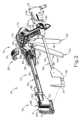
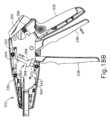
図1Aは、例えば、結腸直腸、胸郭、及び肥満症の処置を含む様々な非内視鏡(「開放」)外科的処置において組織をステープル留め及び切断するように構成された例示的な直角直線状外科用ステープラ(10)を示す。直角直線状外科用ステープラ(10)(「直角直線状カッター」とも呼ばれる)は、一般に、ハンドル組立体(12)と、ハンドル組立体(12)から遠位に延在するシャフト組立体(14)と、シャフト組立体(14)の遠位端にあるエンドエフェクタ(16)と、を含む。以下に記載するように、エンドエフェクタ(16)は、エンドエフェクタ(16)がシャフト組立体(14)によって画定される長手方向軸線に対して直角に横切るように延在する平面内の組織をクランプし、ステープル留めし、かつ切断するように、「直角」構成が設けられている。 I. Overview of an Exemplary Right-Angle Surgical Stapler FIGURE 1A illustrates an exemplary right-angle linear surgical stapler (10) configured to staple and cut tissue in a variety of non-endoscopic ("open") surgical procedures including, for example, colorectal, thoracic, and bariatric procedures. The right-angle linear surgical stapler (10) (also referred to as a "right-angle linear cutter") generally includes a handle assembly (12), a shaft assembly (14) extending distally from the handle assembly (12), and an end effector (16) at the distal end of the shaft assembly (14). As described below, the end effector (16) is provided with a "right-angle" configuration such that the end effector (16) clamps, staples, and cuts tissue in a plane that extends transversely at a right angle to a longitudinal axis defined by the shaft assembly (14).
以下により詳細に記載するように、外科用ステープラ(10)は、患者に対する外科的処置の間にハンドル組立体(12)を介してエンドエフェクタ(16)を操作するための複数の作動システムを含む。具体的には、外科用ステープラ(10)は、エンドエフェクタ(16)内に組織を最初に保持するように動作可能な組織保持ピン作動システム(20)と、エンドエフェクタ(16)を用いて組織をクランプするように動作可能な閉鎖システム(22)と、その後に、エンドエフェクタ(16)を用いて組織をステープル留め及び切断するように動作可能な発射システム(24)と、を含む。As described in more detail below, the surgical stapler (10) includes multiple actuation systems for manipulating the end effector (16) via the handle assembly (12) during a surgical procedure on a patient. Specifically, the surgical stapler (10) includes a tissue retaining pin actuation system (20) operable to initially retain tissue within the end effector (16), a closure system (22) operable to clamp the tissue with the end effector (16), and a firing system (24) operable to thereafter staple and sever the tissue with the end effector (16).
本明細書の教示は、直線状のステープル列及び組織内の直線状切断線に適用するように構成された「直線状」外科用ステープラ(10)の文脈で示され記載されているが、本明細書の教示のうちの任意の1つ又は2つ以上が、本明細書に参考として組み込まれた参考文献のうちの任意の1つ又は2つ以上に開示されたタイプの外科用ステープラのように、非直線状の(例えば、湾曲した)構成でステープル列及び組織の切断線に適用するように構成された外科用ステープラに適用されてもよいことが理解されるであろう。Although the teachings herein are shown and described in the context of a "linear" surgical stapler (10) configured to apply linear staple rows and linear cut lines in tissue, it will be understood that any one or more of the teachings herein may also be applied to surgical staplers configured to apply staple rows and cut lines in tissue in a non-linear (e.g., curved) configuration, such as surgical staplers of the type disclosed in any one or more of the references incorporated by reference herein.
A.外科用ステープラのハンドル組立体及びシャフト組立体
図1Aに示すように、ハンドル組立体(12)は、ピストルグリップ(32)を画定するハウジング(30)と、ハンドルハウジング(30)の上部に摺動可能に配設されたサドル形状の摺動部(34)と、枢動可能な閉鎖トリガ(36)と、枢動可能な発射トリガ(38)と、を含む。閉鎖トリガ(36)及び発射トリガ(38)は、シャフト組立体(14)を介してエンドエフェクタ(16)と動作可能に連結され、それにより、エンドエフェクタ(16)は、閉鎖トリガ(36)の作動に応じて閉鎖し、かつそれによって組織をクランプするように構成され、その後、発射トリガ(38)の作動に応じて組織をステープル留めしかつ切断する(すなわち、「発射する」)ように構成されている。図1Aは、エンドエフェクタ(16)が、カートリッジハウジング(162)と、エンドエフェクタ(16)内に取り付けられた(又は「リロードされた」)交換可能なステープルカートリッジユニット(160)のアンビル(210)との間に画定された間隙(G)(又は「アパーチャ」)内に横方向に組織を受容するように構成されるように、非作動構成にある摺動部(34)及び閉鎖トリガ(36)を示す。図1Bに示すように、摺動部(34)をエンドエフェクタ(16)に向かって遠位に並進させることにより、ステープルカートリッジユニット(160)の組織保持ピン(176)が遠位に延在して、アンビル(210)とカートリッジハウジング(162)との間に組織を捕捉する。図1Cに示すように、続いて閉鎖トリガ(36)をピストルグリップ(32)に向かって作動させると、カートリッジハウジング(162)がアンビル(210)に向かって遠位に駆動され、それによって組織がその間にクランプされる。図1Dに示すように、続いて、ピストルグリップ(32)に向かって発射トリガ(38)を作動させると、クランプされた組織内にステープルが遠位に駆動され、また、以下でより詳細に記載するように、ナイフ部材(194)(図8参照)を用いて、形成されたステープルラインの間で組織を切断する。 A. Surgical Stapler Handle and Shaft Assemblies As shown in FIGURE 1A, the handle assembly (12) includes a housing (30) defining a pistol grip (32), a saddle-shaped slider (34) slidably disposed on top of the handle housing (30), a pivotable closure trigger (36), and a pivotable firing trigger (38). The closure trigger (36) and firing trigger (38) are operatively coupled to the end effector (16) via the shaft assembly (14) such that the end effector (16) is configured to close, and thereby clamp tissue, in response to actuation of the closure trigger (36), and thereafter staple and cut (i.e., "fire") tissue in response to actuation of the firing trigger (38). FIG 1A shows the slider (34) and closure trigger (36) in an unactuated configuration such that the end effector (16) is configured to receive tissue laterally into a gap (G) (or "aperture") defined between the cartridge housing (162) and an anvil (210) of a replaceable staple cartridge unit (160) mounted (or "reloaded") within the end effector (16). As shown in FIG 1B, distal translation of the slider (34) toward the end effector (16) causes the tissue retaining pins (176) of the staple cartridge unit (160) to extend distally to capture tissue between the anvil (210) and the cartridge housing (162). Subsequent actuation of the closure trigger (36) toward the pistol grip (32) drives the cartridge housing (162) distally toward the anvil (210), thereby clamping the tissue therebetween, as shown in FIG 1C. As shown in FIG. 1D, subsequent actuation of firing trigger (38) toward pistol grip (32) drives staples distally into the clamped tissue and uses knife member (194) (see FIG. 8) to sever the tissue between the formed staple lines, as described in more detail below.
図2に示すように、外科用ステープラ(10)は、組織保持ピン作動システム(20)、閉鎖システム(22)、及び発射システム(24)を支持するステープラ(10)のフレーム構造体を画定するために協働する一対の長手方向に延在するサイドプレート(40)を含む。各サイドプレート(40)は、ハンドルハウジング(30)内に収容された近位フレーム部分(42)と、シャフト組立体(14)のそれぞれの外側の横方向の側面を画定する中間シャフト部分(44)と、上方に延在する遠位フック(47)を有する遠位ジョー部分(46)と、を含む。遠位ジョー部分(46)は、以下に記載される閉鎖バー(50)の遠位端と協働して、ステープルカートリッジユニット(160)を取り外し可能に受容するエンドエフェクタ(16)のU字型遠位支持構造体(48)を画定する。本明細書で使用するとき、用語「U字型」は、本明細書に示される側面図のいずれかにおいて、エンドエフェクタ(16)によって提示される形状を指す。As shown in FIG. 2, the surgical stapler (10) includes a pair of longitudinally extending side plates (40) that cooperate to define a frame structure of the stapler (10) that supports the tissue retaining pin actuation system (20), the closure system (22), and the firing system (24). Each side plate (40) includes a proximal frame portion (42) housed within the handle housing (30), an intermediate shaft portion (44) that defines a respective outer lateral side of the shaft assembly (14), and a distal jaw portion (46) having an upwardly extending distal hook (47). The distal jaw portion (46) cooperates with a distal end of a closure bar (50) described below to define a U-shaped distal support structure (48) of the end effector (16) that removably receives a staple cartridge unit (160). As used herein, the term "U-shaped" refers to the shape presented by the end effector (16) in any of the side views shown herein.
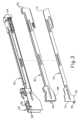
図3に示すように、サイドプレート(40)の間に摺動可能に配設され、かつそれによって支持されているのは、ハンドル組立体(12)とステープルカートリッジユニット(160)とを作動的に連結する、作動システム(20、22、24)の細長い作動可能な構成要素であり、閉鎖バー(50)、ステープルバー(60)、及びナイフバー(70)を含む。閉鎖バー(50)は、ステープルカートリッジユニット(160)を受容して支持するように構成されたカートリッジ受容遠位部分(52)を含む。閉鎖バー(50)及びステープルバー(60)は各々、互いに離間した第1及び第2の横方向の側面と、それらの間に長手方向に延在する内側チャネルと、を有する両面構造体として構成される。この構成により、ナイフバー(70)は、ステープルバー(60)の長手方向の内側チャネル内に入れ子式でかつ摺動可能に配設され、ステープルバー(60)も同様にして閉鎖バー(50)の長手方向の内側チャネル内に入れ子式でかつ摺動可能に配設される、シャフト組立体(14)の配置が可能になる。更に、ステープルバー(60)及びナイフバー(70)は、エンドエフェクタ(16)の独立した閉鎖及び発射を可能にする長手方向運動の範囲にわたって閉鎖バー(50)とは独立して長手方向に並進可能である。以下により詳細に記載するように、閉鎖バー(50)は、閉鎖トリガ(36)の作動に応じて組織をクランプするために、アンビル(210)に対して長手方向にカートリッジハウジング(162)を作動させるように動作可能である。ステープルバー(60)は、クランプされた組織をステープル留めするために、ステープルドライバ部材(186)(図8参照)をカートリッジハウジング(162)に対して長手方向に作動させるように動作可能である。ナイフバー(70)は、クランプされた組織を切断するために、カートリッジハウジング(162)及びステープルドライバ部材(186)に対して長手方向にナイフ部材(194)(図8参照)を作動させるように動作可能である。As shown in FIG. 3, slidably disposed between and supported by the side plates (40) are elongated actuable components of the actuation system (20, 22, 24) that operatively couple the handle assembly (12) and the staple cartridge unit (160), including a closure bar (50), a staple bar (60), and a knife bar (70). The closure bar (50) includes a cartridge-receiving distal portion (52) configured to receive and support the staple cartridge unit (160). The closure bar (50) and the staple bar (60) are each configured as a double-sided structure having first and second spaced-apart lateral sides and an inner channel extending longitudinally therebetween. This configuration allows for arrangement of the shaft assembly (14) where the knife bar (70) is telescopically and slidably disposed within the inner longitudinal channel of the staple bar (60), which in turn is telescopically and slidably disposed within the inner longitudinal channel of the closure bar (50). Additionally, the staple bar (60) and the knife bar (70) are longitudinally translatable independently of the closure bar (50) through a range of longitudinal motion that allows for independent closure and firing of the end effector (16). As described in more detail below, the closure bar (50) is operable to actuate the cartridge housing (162) longitudinally relative to the anvil (210) to clamp tissue in response to actuation of the closure trigger (36). The staple bar (60) is operable to actuate the staple driver member (186) (see FIG. 8) longitudinally relative to the cartridge housing (162) to staple the clamped tissue. The knife bar (70) is operable to actuate the knife member (194) (see FIG. 8) longitudinally relative to the cartridge housing (162) and the staple driver member (186) to sever the clamped tissue.
外科用ステープラ(10)の組織保持ピン作動システム(20)は、ハンドル組立体(12)の摺動部(34)と、ステープルカートリッジユニット(160)の組織保持ピン(176)と、シャフト組立体(14)の上側に沿って長手方向に延在する細長い押棒(80)と、ハンドル組立体(12)内に摺動可能に配設された押棒ドライバ(82)と、を含む。押棒(80)の遠位端は、ステープルカートリッジユニット(160)をエンドエフェクタ(16)の遠位支持構造体(48)に挿入すると、組織保持ピン(176)と解放可能に連結するように構成されている。押棒(80)の近位端は、押棒ドライバ(82)と連結され、これは摺動部(34)と連結される。したがって、近位位置と遠位位置との間の摺動部(34)を長手方向に並進させることにより、格納位置と伸張位置との間でカートリッジハウジング(162)に対する組織保持ピン(176)の長手方向の並進が駆動される。図1Aに示すように、組織保持ピン(176)は、摺動部(34)が近位位置にあるとき、保持ピン(176)がカートリッジハウジング(162)内に収容される格納位置を呈するように構成されている。図1Bに示すように、組織保持ピン(176)は、摺動部(34)が遠位位置に進んだときに、保持ピン(176)の遠位端がアンビル(210)に係合し、それによって、ステープルカートリッジユニット(160)の間隙(G)内に配置された組織を保持する、伸張位置を呈するように構成される。The tissue retaining pin actuation system (20) of the surgical stapler (10) includes a slider (34) of the handle assembly (12), a tissue retaining pin (176) of the staple cartridge unit (160), an elongated pusher bar (80) extending longitudinally along the upper side of the shaft assembly (14), and a pusher bar driver (82) slidably disposed within the handle assembly (12). The distal end of the pusher bar (80) is configured to releasably couple to the tissue retaining pin (176) upon insertion of the staple cartridge unit (160) into the distal support structure (48) of the end effector (16). The proximal end of the pusher bar (80) is coupled to the pusher bar driver (82), which is coupled to the slider (34). Thus, longitudinal translation of the slide (34) between the proximal and distal positions drives longitudinal translation of the tissue retaining pin (176) relative to the cartridge housing (162) between the retracted and extended positions. As shown in FIG. 1A, the tissue retaining pin (176) is configured to assume a retracted position in which the retaining pin (176) is housed within the cartridge housing (162) when the slide (34) is in the proximal position. As shown in FIG. 1B, the tissue retaining pin (176) is configured to assume an extended position in which the distal end of the retaining pin (176) engages the anvil (210), thereby retaining tissue disposed within the gap (G) of the staple cartridge unit (160) when the slide (34) is advanced to the distal position.
外科用ステープラ(10)の閉鎖システム(22)は、ハンドル組立体(12)の閉鎖トリガ(36)及び閉鎖バー(50)を含む。図2及び図4A~図4Cに示すように、閉鎖トリガ(36)は、一対の横方向に延在するポスト(90)を中心としてハンドルハウジング(30)と枢動可能に連結される。垂直方向にスロット付きの遠位部分を有する閉鎖トリガ(36)の上部アーム(92)は、一対の閉鎖リンク(96)によって閉鎖バー(50)の近位端と動作可能に連結される。各閉鎖リンク(96)の近位端は、閉鎖トリガ上部アーム(92)の横方向に延在するポスト(93)と枢動可能に連結される。各閉鎖リンク(96)の遠位端は、閉鎖バー(50)の横方向に延在するポスト(54)を中心として閉鎖バー(50)の近位端と枢動可能に連結される。The closure system (22) of the surgical stapler (10) includes a closure trigger (36) and a closure bar (50) of the handle assembly (12). As shown in Figures 2 and 4A-4C, the closure trigger (36) is pivotally connected to the handle housing (30) about a pair of laterally extending posts (90). An upper arm (92) of the closure trigger (36) having a vertically slotted distal portion is operably connected to a proximal end of the closure bar (50) by a pair of closure links (96). The proximal end of each closure link (96) is pivotally connected to a laterally extending post (93) of the closure trigger upper arm (92). The distal end of each closure link (96) is pivotally connected to a proximal end of the closure bar (50) about a laterally extending post (54) of the closure bar (50).
図4A~図4Bに示すように、ピストルグリップ(32)に向かって閉鎖トリガ(36)を枢動させる枢動により、閉鎖トリガ上部アーム(92)が遠位かつ下方に前進され、それによって閉鎖リンク(96)を介して閉鎖バー(50)が遠位に駆動される。次いで、閉鎖バー(50)のカートリッジ受容遠位部分(52)は、カートリッジハウジング(162)をアンビル(210)に向かって遠位に駆動する。このようにして、エンドエフェクタ(16)は、組織がエンドエフェクタ(16)内に位置付け可能である開放状態(図1A~図1B)から、組織がカートリッジハウジング(162)とアンビル(210)との間にクランプされる閉鎖状態(図1C)へと作動される。ハンドル組立体(12)のピストルグリップ(32)内に収容された閉鎖戻りばね(98)は、閉鎖トリガ(36)を非作動状態に向かって弾性的に付勢し、それにより、エンドエフェクタ(16)を開放状態に向かって弾性的に付勢する。As shown in FIGS. 4A-4B, pivoting the closure trigger (36) toward the pistol grip (32) advances the closure trigger upper arm (92) distally and downwardly, thereby driving the closure bar (50) distally via the closure link (96). The cartridge-receiving distal portion (52) of the closure bar (50) then drives the cartridge housing (162) distally toward the anvil (210). In this manner, the end effector (16) is actuated from an open state (FIGS. 1A-1B), in which tissue is positionable within the end effector (16), to a closed state (FIG. 1C), in which tissue is clamped between the cartridge housing (162) and the anvil (210). A closure return spring (98) housed within the pistol grip (32) of the handle assembly (12) resiliently biases the closure trigger (36) toward the inactivated state, thereby resiliently biasing the end effector (16) toward the open state.
本変形例では、閉鎖バー(50)は、操作者が閉鎖トリガ(36)を握ったときに、組織保持ピン作動システム(20)と協働して、保持ピン(176)をその伸張位置まで遠位に自動的に作動させるように更に構成されている。これに関して、図4A~図4Bに最もよく示すように、ハンドル組立体(12)は、閉鎖リンク(96)の外側に沿って回転可能に配設された一対のカムヨーク(100)を更に含む。各カムヨーク(100)は、閉鎖バー(50)のそれぞれの近位ポスト(54)を摺動可能に受容する角度付きスロット(102)を含む。閉鎖トリガ(36)がピストルグリップ(32)に向かって作動すると、近位ポスト(54)は、カムヨーク(100)を遠位に回転可能に駆動させて、ヨーク(100)のカムローブ(104)が押棒ドライバ(82)の対応するサイドポスト(84)と係合し、それによって押棒(80)、ひいては組織保持ピン(176)を遠位に作動させる。エンドエフェクタ(16)の閉鎖中の組織保持ピン(176)のこのような自動伸張は、操作者が閉鎖トリガ(36)を作動する前に摺動部(34)を介して保持ピン(176)を遠位に手動で作動させなかった場合に有用であり得る。In this variation, the closure bar (50) is further configured to cooperate with the tissue retaining pin actuation system (20) to automatically actuate the retaining pin (176) distally to its extended position when the operator squeezes the closure trigger (36). In this regard, as best shown in FIGS. 4A-4B, the handle assembly (12) further includes a pair of cam yokes (100) rotatably disposed along the exterior of the closure link (96). Each cam yoke (100) includes an angled slot (102) that slidably receives a respective proximal post (54) of the closure bar (50). When the closure trigger (36) is actuated toward the pistol grip (32), the proximal post (54) rotatably drives the cam yoke (100) distally such that the cam lobes (104) of the yoke (100) engage corresponding side posts (84) of the pusher bar driver (82), thereby actuating the pusher bar (80) and thus the tissue retaining pin (176) distally. Such automatic extension of the tissue retaining pin (176) during closure of the end effector (16) can be useful if the operator does not manually actuate the retaining pin (176) distally via the slide (34) prior to actuating the closure trigger (36).
本実施例の閉鎖システム(22)は、閉鎖トリガ(36)を作動位置で解放可能にロックして、閉鎖トリガ(36)を継続的に握ることなく、エンドエフェクタ(16)を用いて組織の効果的なクランプを提供できるように更に構成されている。図4A~図4Bに最もよく示すように、解放ボタン(110)は、ハンドル組立体(12)の近位端に枢動可能に配設される。ロック爪(112)は、解放ボタン(110)の上端から遠位に延在し、解放ボタンばね(116)を介して、閉鎖トリガ上部アーム(92)の上端と接触するように弾性的に付勢されている爪状ラグ(114)を含む。したがって、閉鎖トリガ(36)がピストルグリップ(32)に向かって握られると、爪状ラグ(114)は、閉鎖トリガ上部アーム(92)の上面に沿って摺動するように構成されている。図4Bに示すように、閉鎖トリガ(36)が完全に作動位置に到達すると、爪状ラグ(114)は、閉鎖トリガ上部アーム(92)の近位上部ノッチ(94)内に入り込み、それによって閉鎖トリガ(36)を作動位置に完全にロックする。操作者がエンドエフェクタ(16)を再開放することを望む場合、例えば、エンドエフェクタ(16)内に組織を再配置するか、又は発射が完了した後に組織を解放するために、操作者は解放ボタン(110)を押下して、爪状ラグ(114)を閉鎖トリガ(36)から係合解除することができる。閉鎖復帰ばね(98)によって提供される弾性的な付勢によって、閉鎖トリガ(36)は、その後非作動状態に戻り、エンドエフェクタ(16)は、図1A及び図4Aに示される開放状態に戻る。The closure system (22) of this embodiment is further configured to releasably lock the closure trigger (36) in an actuated position to provide effective clamping of tissue with the end effector (16) without continually squeezing the closure trigger (36). As best shown in FIGS. 4A-4B, the release button (110) is pivotally disposed at the proximal end of the handle assembly (12). The locking pawl (112) extends distally from the upper end of the release button (110) and includes a pawl-like lug (114) that is resiliently biased into contact with the upper end of the closure trigger upper arm (92) via the release button spring (116). Thus, when the closure trigger (36) is squeezed toward the pistol grip (32), the pawl-like lug (114) is configured to slide along the upper surface of the closure trigger upper arm (92). As shown in FIG. 4B, when the closure trigger (36) reaches the fully actuated position, the pawl lug (114) fits into the proximal upper notch (94) of the closure trigger upper arm (92), thereby fully locking the closure trigger (36) in the actuated position. If the operator wishes to reopen the end effector (16), for example to reposition tissue within the end effector (16) or to release tissue after firing is complete, the operator can depress the release button (110) to disengage the pawl lug (114) from the closure trigger (36). Due to the resilient bias provided by the closure return spring (98), the closure trigger (36) then returns to the unactuated state and the end effector (16) returns to the open state shown in FIGS. 1A and 4A.
外科用ステープラ(10)の発射システム(24)は、ハンドル組立体(12)の発射トリガ(38)、ステープルバー(60)、ナイフバー(70)、及びステープルカートリッジユニット(160)のステープルドライバ部材(186)及びナイフ部材(194)を含む。ナイフバー(70)及びステープルドライバ部材(186)の特徴部は、図8に関連して以下でより詳細に記載される。図2及び図4Aに示すように、本実施例の発射トリガ(38)は、ハンドルハウジング(30)から下方に延在し、操作者によって係合可能である下部シュラウド(120)と、下部シュラウド(120)から上方かつ遠位に延在し、ハンドルハウジング(30)とともに位置付けられている円弧状上部アーム(122)を有する一対のプレートと、円弧状上部アーム(122)の自由な遠位上端の間で横方向に延在する回転可能なカムピン(124)と、ハンドルハウジング(30)内の円弧状上部アーム(122)の下端から遠位に延在する発射ロックアウト突起部(126)と、を有する、アセンブリとして構成されている。カムピン(124)は、本願と同日出願の「Cartridge Based Lockout Mechanism for Right Angle Surgical Stapler」と題する米国特許出願第[代理人参照番号END9088USNP1](その開示は参照により本明細書に組み込まれる)の教示のいずれかに従って更に構成されかつ動作可能であり得る。The firing system (24) of the surgical stapler (10) includes the firing trigger (38) of the handle assembly (12), the staple bar (60), the knife bar (70), and the staple driver member (186) and knife member (194) of the staple cartridge unit (160). Features of the knife bar (70) and the staple driver member (186) are described in more detail below in connection with FIG. As shown in FIGS. 2 and 4A , the firing trigger (38) of this embodiment is configured as an assembly having a lower shroud (120) extending downwardly from the handle housing (30) and engageable by an operator, a pair of plates having arcuate upper arms (122) extending upwardly and distally from the lower shroud (120) and positioned with the handle housing (30), a rotatable cam pin (124) extending laterally between the free distal upper ends of the arcuate upper arms (122), and a firing lockout protrusion (126) extending distally from the lower end of the arcuate upper arms (122) within the handle housing (30). The cam pin (124) may further be configured and operable in accordance with any of the teachings of U.S. Patent Application No. [Attorney Reference No. END9088USNP1], entitled "Cartridge Based Lockout Mechanism for Right Angle Surgical Stapler," filed on the same day herewith, the disclosure of which is incorporated herein by reference.
発射トリガ(38)は、横方向に延在する枢動ピン(128)を介してハンドルハウジング(30)と枢動可能に連結されている。加えて、発射トリガ(38)は、閉鎖トリガ(36)がピストルグリップ(32)に向かって作動する際に、発射トリガ(38)の円弧状上部アーム(122)が閉鎖トリガ上部アーム(92)のスロット付き遠位部分内に受容されるように、閉鎖トリガ(36)の遠位に位置付けられている。図4A~図4Bに示すように、操作者が閉鎖トリガ(36)をピストルグリップ(32)に向かって完全に握ると、閉鎖トリガ上部アーム(92)の遠位スロット付き部分内に配設された遠位に面するレッジ(95)が、発射トリガ(38)のカムピン(124)と係合し、カムピン(124)を初期量だけ遠位に駆動する。これにより、図4Bに示すように、発射トリガ(38)の下端は、閉鎖トリガ(36)と同時にピストルグリップ(32)に向かって部分的に枢動する。The firing trigger (38) is pivotally connected to the handle housing (30) via a laterally extending pivot pin (128). In addition, the firing trigger (38) is positioned distal to the closure trigger (36) such that the arcuate upper arm (122) of the firing trigger (38) is received within the slotted distal portion of the closure trigger upper arm (92) as the closure trigger (36) is actuated toward the pistol grip (32). As shown in FIGS. 4A-4B, when the operator fully squeezes the closure trigger (36) toward the pistol grip (32), a distally facing ledge (95) disposed within the distal slotted portion of the closure trigger upper arm (92) engages the cam pin (124) of the firing trigger (38) and drives the cam pin (124) distally an initial amount. This causes the lower end of the firing trigger (38) to partially pivot toward the pistol grip (32) simultaneously with the closure trigger (36), as shown in FIG. 4B.
図4Cに示すように、一度エンドエフェクタ(16)が完全な閉鎖状態に達して、ピストルグリップ(32)に向かって発射トリガ(38)を更に作動させると、エンドエフェクタ(16)を「発射する」ように動作する。具体的には、カムピン(124)の外側部分は、ステープルバー(60)の近位縁部(62)と係合し、ひいてはステープルバー(60)を閉鎖バー(50)に対して遠位に駆動する。図12A~図12Dに関連して以下でより詳細に記載するように、ステープルバー(60)の遠位縁部(64)は、ステープルカートリッジハウジング(162)内のステープルドライバ部材(186)の近位端に係合し、それにより、ステープルドライバ部材(186)がステープルカートリッジハウジング(162)を通って遠位に駆動し、エンドエフェクタ(16)によってクランプされた組織内にステープルを駆動する。発射トリガ(38)がその完全な作動状態に向かって作動すると、カムピン(124)の中間部分が発射トリガ(38)の円弧状上部アーム(122)間に配設され、ナイフバー(70)の丸みを帯びた近位縁部(72)と係合し、それにより、ナイフバー(70)を閉鎖バー(50)に対して遠位に駆動させる。図12A~図12Dに関連して以下でより詳細に記載するように、ナイフバー(70)の遠位縁部(74)は、ステープルカートリッジハウジング(162)内のナイフ部材(194)の近位端に係合し、それにより、ナイフ部材(194)がステープルドライバ部材(186)を通って遠位に駆動し、エンドエフェクタ(16)によってクランプされた組織を切断する。As shown in FIG. 4C, once the end effector (16) has reached a fully closed state, further actuation of the firing trigger (38) toward the pistol grip (32) operates to "fire" the end effector (16). Specifically, the outer portion of the cam pin (124) engages the proximal edge (62) of the staple bar (60), thus driving the staple bar (60) distally relative to the closure bar (50). As described in more detail below in connection with FIGS. 12A-12D, the distal edge (64) of the staple bar (60) engages the proximal end of a staple driver member (186) within the staple cartridge housing (162), thereby driving the staple driver member (186) distally through the staple cartridge housing (162) and into the tissue clamped by the end effector (16). As the firing trigger (38) is actuated toward its fully actuated state, an intermediate portion of the cam pin (124) is disposed between the arcuate upper arms (122) of the firing trigger (38) and engages the rounded proximal edge (72) of the knife bar (70), thereby driving the knife bar (70) distally relative to the closure bar (50). As described in more detail below in connection with FIGS. 12A-12D, the distal edge (74) of the knife bar (70) engages the proximal end of the knife member (194) within the staple cartridge housing (162), thereby driving the knife member (194) distally through the staple driver member (186) to sever the tissue clamped by the end effector (16).
本実施例の発射システム(24)は、発射トリガ(38)がピストルグリップ(32)に向かって最初の運動範囲を通して作動されるときに、ステープルバー(60)及びナイフバー(70)がともに遠位に並進し、かつ発射トリガ(38)がピストルグリップ(32)に向かって最終の運動範囲を通して更に作動されるとき、ナイフバー(70)がステープルバー(60)に対して遠位に並進し続けるように好適に構成されている。有利なことに、このような構成は、エンドエフェクタ(16)によってクランプされた組織が完全にステープル留めされ、組織がナイフ部材(194)によって切断される前に、意図された組織切断線に沿って適切な止血が達成されることを確実にする。The firing system (24) of this embodiment is preferably configured such that when the firing trigger (38) is actuated through an initial range of motion toward the pistol grip (32), both the staple bar (60) and the knife bar (70) translate distally, and when the firing trigger (38) is further actuated through a final range of motion toward the pistol grip (32), the knife bar (70) continues to translate distally relative to the staple bar (60). Advantageously, such a configuration ensures that the tissue clamped by the end effector (16) is fully stapled and that proper hemostasis is achieved along the intended tissue cut line before the tissue is severed by the knife member (194).
図2に示すように、発射システム(24)は、ハンドル組立体(12)内に収容されたナイフ戻しばね(130)を更に含む。ナイフ戻しばね(130)は、その遠位端でナイフバー(70)の遠位端に定着され、その近位端で閉鎖バー(50)の遠位端に定着される。したがって、ナイフ戻しばね(130)は、発射トリガ(38)が解放されると、閉鎖バー(50)及びステープルバー(60)に対してナイフバー(70)を近位に弾性的に付勢するように動作可能である。図3及び図12A~図12Dに示すように、ナイフバー(70)は、遠位フック(76)を含み、それがナイフ部材(194)によって捕捉されることによってナイフ部材(194)をナイフバー(70)に軸方向に固着する。したがって、操作者が発射ストロークを完了した後に発射トリガ(38)を解放すると、ナイフバー(70)及びナイフ部材(194)は自動的に近位に後退して、ナイフ部材(194)の遠位切断縁部(200)をステープルカートリッジハウジング(162)内に安全に収容する。As shown in FIG. 2, the firing system (24) further includes a knife return spring (130) housed within the handle assembly (12). The knife return spring (130) is anchored at its distal end to the distal end of the knife bar (70) and at its proximal end to the distal end of the closure bar (50). Thus, the knife return spring (130) is operable to resiliently bias the knife bar (70) proximally relative to the closure bar (50) and the staple bar (60) upon release of the firing trigger (38). As shown in FIGS. 3 and 12A-12D, the knife bar (70) includes a distal hook (76) that is captured by the knife member (194) to axially secure the knife member (194) to the knife bar (70). Thus, when the operator releases the firing trigger (38) after completing the firing stroke, the knife bar (70) and knife member (194) automatically retract proximally to safely house the distal cutting edge (200) of the knife member (194) within the staple cartridge housing (162).
図2に示すように、本実施例の外科用ステープラ(10)は、枢動可能レバー(140)の形態である近位発射ロックアウト特徴部を更に含むが、これは、エンドエフェクタ(16)が閉鎖トリガ(36)によって完全に閉鎖されるまで、発射トリガ(38)の作動を抑制するように動作可能である。発射ロックアウトレバー(140)は、ハンドル組立体(12)内に収容され、左のサイドプレート(40)の近位フレーム部分(42)の外側に枢動可能に取り付けられる。発射ロックアウトレバー(140)は、ばね(146)によって、近位ロックアウトレバー(140)の下部タブ(142)が発射トリガ(38)の発射ロックアウト突起部(126)の下方への移動を阻止する位置に向かって弾性的に付勢されているが、それにより、エンドエフェクタ(16)を閉鎖するために閉鎖トリガ(36)が完全に作動していない場合には、発射トリガ(38)の作動が抑制されるようになっている。閉鎖トリガ(36)が完全な作動状態に達すると、発射ロックアウトレバー(140)の上部アーム(144)は、解放ボタン(110)の爪状ラグ(114)によって下方に駆動されるが、これにより、下部タブ(142)を発射ロックアウト突起部(126)から離れるように回転させ、発射トリガ(38)の作動を可能にする。発射ロックアウトレバー(140)及びその例示的な変形例は、以下により詳細に記載される。As shown in FIG. 2, the surgical stapler (10) of this embodiment further includes a proximal firing lockout feature in the form of a pivotable lever (140) that is operable to inhibit actuation of the firing trigger (38) until the end effector (16) is fully closed by the closure trigger (36). The firing lockout lever (140) is housed within the handle assembly (12) and pivotally mounted to the outside of the proximal frame portion (42) of the left side plate (40). The firing lockout lever (140) is resiliently biased by a spring (146) toward a position where the lower tab (142) of the proximal lockout lever (140) blocks downward movement of the firing lockout protrusion (126) of the firing trigger (38), thereby inhibiting actuation of the firing trigger (38) when the closure trigger (36) is not fully actuated to close the end effector (16). When the closure trigger (36) reaches its fully actuated state, the upper arm (144) of the firing lockout lever (140) is driven downward by the pawl-like lug (114) of the release button (110), which rotates the lower tab (142) away from the firing lockout protrusion (126) and allows actuation of the firing trigger (38). The firing lockout lever (140) and its exemplary variations are described in more detail below.
図示されていないが、外科用ステープラ(10)のシャフト組立体(14)は、関節接合部など様々な追加の構成要素を含んでもよく、あるいは、シャフト組立体(14)がハンドル組立体(12)に対してモジュール化されるように、様々な構成要素の再配置を含んでもよい。Although not shown, the shaft assembly (14) of the surgical stapler (10) may include various additional components, such as an articulation joint, or may include rearrangements of various components such that the shaft assembly (14) is modular with respect to the handle assembly (12).
B.外科用ステープラのエンドエフェクタ
外科用ステープラ(10)のエンドエフェクタ(16)は、サイドプレート(40)の遠位部分、閉鎖バー(50)のカートリッジ受容遠位部分(52)、ステープルバー(60)及びナイフバー(70)の遠位部分によって画定される遠位支持構造体(48)、並びに交換可能なステープルカートリッジユニット(160)を含む。図5~図8に最もよく示すように、本変形例のステープルカートリッジユニット(160)は、ステープル留めしかつ切断される患者組織を受容するための軸方向の間隙(G)をその間に画定するように、互いに離間したカートリッジハウジング(162)及びアンビル(210)を含む。カートリッジハウジング(162)は、アンビル(210)に対して組織をクランプするように構成され、アンビル(210)とともにシャフト組立体(14)の長手方向軸に対して横切るように延在し、遠位に面したデッキ(164)を含み、その結果、エンドエフェクタ(16)に「直角」構成を提供する。 B. Surgical Stapler End Effector The end effector (16) of the surgical stapler (10) includes a distal support structure (48) defined by a distal portion of a side plate (40), a cartridge receiving distal portion (52) of a closure bar (50), distal portions of a staple bar (60) and a knife bar (70), and a replaceable staple cartridge unit (160). As best shown in Figures 5-8, the staple cartridge unit (160) of this variation includes a cartridge housing (162) and an anvil (210) spaced apart from one another to define an axial gap (G) therebetween for receiving patient tissue to be stapled and severed. Cartridge housing (162) is configured to clamp tissue against anvil (210) and includes a distally-facing deck (164) that extends transversely to the longitudinal axis of shaft assembly (14) along with anvil (210), thereby providing end effector (16) with a "right angle" configuration.
カートリッジデッキ(164)は、その中にナイフ(198)を摺動可能に受容するように構成された細長い直線状ナイフスロット(166)と、細長い直線状ナイフスロット(166)のいずれかの側に沿って直線状の列で配置され、複数の未形成ステープル(170)を内部に収容するように構成された複数のステープル開口部(168)と、を含む。本実施例のデッキ(164)は、ステープル開口部(168)とともに挿入され、組織がデッキ(164)とアンビル(210)との間にクランプされる際に患者組織の把持及び圧縮を最適化するように構成された、複数のスタンドオフ特徴部(172)を更に含む。デッキ(164)は、2019年1月14日出願の「Surgical Stapler with Sloped Staple Deck for Varying Tissue Compression」と題する米国特許出願第16/234,740号(その開示は参照により本明細書に組み込まれる)の少なくとも一部の教示に従って、更に構成され得る。The cartridge deck (164) includes an elongated linear knife slot (166) configured to slidably receive a knife (198) therein, and a plurality of staple openings (168) arranged in linear rows along either side of the elongated linear knife slot (166) and configured to receive a plurality of unformed staples (170) therein. The deck (164) of this example further includes a plurality of standoff features (172) configured to be inserted with the staple openings (168) to optimize gripping and compression of patient tissue when the tissue is clamped between the deck (164) and the anvil (210). The deck (164) may be further configured in accordance with at least some of the teachings of U.S. Patent Application No. 16/234,740, filed January 14, 2019, entitled "Surgical Stapler with Sloped Staple Deck for Varying Tissue Compression," the disclosure of which is incorporated herein by reference.
カートリッジハウジング(162)の細長い上部本体部分(174)は、組織保持ピン(176)と、組織保持ピン(176)の近位端に固着された連結具(180)と、を摺動可能に収容する。連結具(180)は、ステープルカートリッジユニット(160)がエンドエフェクタ(16)の遠位支持構造体(48)内に着座されたときに、組織保持ピン(176)を組織保持ピン作動システム(20)の押棒(80)の遠位端と解放可能に連結するように構成される。上部本体部分(174)の近位端に固着されたエンドキャップ部材(182)は、組織保持ピン(176)及び連結具(180)をカートリッジハウジング(162)内で近位に拘束するように構成されており、一方で、組織保持ピン(176)がその近位の格納位置(図1A及び図12Aを参照)とその遠位の伸長位置(図1B及び図12Bを参照)との間で並進することを可能にしている。組織保持ピン(176)は、保持ピン(176)がアンビル(210)に向かって延在するときに組織を貫通するように構成されたテーパ状の遠位先端部(178)を含む。The elongated upper body portion (174) of the cartridge housing (162) slidably receives a tissue retaining pin (176) and a coupler (180) secured to a proximal end of the tissue retaining pin (176). The coupler (180) is configured to releasably couple the tissue retaining pin (176) to a distal end of a push rod (80) of the tissue retaining pin actuation system (20) when the staple cartridge unit (160) is seated within the distal support structure (48) of the end effector (16). An end cap member (182) secured to the proximal end of the upper body portion (174) is configured to proximally restrain the tissue retaining pin (176) and the coupling (180) within the cartridge housing (162) while allowing the tissue retaining pin (176) to translate between its proximal retracted position (see FIGS. 1A and 12A) and its distal extended position (see FIGS. 1B and 12B). The tissue retaining pin (176) includes a tapered distal tip (178) configured to penetrate tissue as the retaining pin (176) extends toward the anvil (210).
カートリッジハウジング(162)の下部本体部分(184)は、ステープルドライバ部材(186)及びナイフ部材(194)を内部に摺動可能に受容する。図8に最も良く示すように、本変形例のステープルドライバ部材(186)は、基部(188)と、基部(188)から遠位に突出する複数のステープルドライバ要素(190)と、ステープルドライバ部材(186)を通って軸方向に延在し、ナイフ部材(194)を摺動可能に受容するように構成された内部チャネル(192)と、を含む。各ステープルドライバ要素(190)は、カートリッジハウジング(162)のそれぞれのステープル開口部(168)内に摺動可能に受容され、閉鎖トリガ(36)の作動に応じて、開口部(168)からそれぞれのステープル(170)を駆動するように構成される。本変形例のステープルドライバ要素(190)は基部(188)にしっかりと貼着されているが、基部(188)及びステープルドライバ要素(190)は、他の変形例では別個に提供されてもよいことが理解されるであろう。The lower body portion (184) of the cartridge housing (162) slidably receives a staple driver member (186) and a knife member (194) therein. As best shown in FIG. 8, the staple driver member (186) of this variation includes a base (188), a plurality of staple driver elements (190) projecting distally from the base (188), and an internal channel (192) extending axially through the staple driver member (186) and configured to slidably receive the knife member (194). Each staple driver element (190) is slidably received within a respective staple opening (168) of the cartridge housing (162) and configured to drive a respective staple (170) from the opening (168) in response to actuation of the closure trigger (36). It will be appreciated that although the staple driver element (190) in this variation is securely affixed to the base (188), the base (188) and the staple driver element (190) may be provided separately in other variations.
ナイフ部材(194)は、基部(196)と、基部(196)に固着されかつそこから遠位に延在し、遠位切断縁部(200)を有するナイフ(198)と、を含む。ナイフ(198)は、ナイフ(198)が患者組織上で直線状の切断を行うことを可能にする平坦なプレート状形状で形成される。ナイフ部材(194)は、ステープルドライバ部材(186)の内部チャネル(192)内に摺動可能に受容されるが、このため、ナイフ(198)が、発射トリガ(38)の完全な作動に応じて、エンドエフェクタ(16)によってクランプされた組織を切断するために、ステープルドライバ部材(186)及びカートリッジハウジング(162)の細長い直線状ナイフスロット(166)を通して長手方向に並進するように構成されている。The knife member (194) includes a base (196) and a knife (198) secured to and extending distally therefrom, the knife (198) having a distal cutting edge (200). The knife (198) is formed in a flat, plate-like shape that allows the knife (198) to make a linear cut on patient tissue. The knife member (194) is slidably received within the internal channel (192) of the staple driver member (186) such that the knife (198) is configured to translate longitudinally through the staple driver member (186) and the elongated linear knife slot (166) of the cartridge housing (162) in response to full actuation of the firing trigger (38) to cut tissue clamped by the end effector (16).
図8に最も良く示すように、ステープルカートリッジユニット(160)のアンビル(210)は、遠位プレート部分(212)と、遠位プレート部分(212)の下端から近位に延在する連結アーム(214)と、を含む。遠位プレート部分(212)は、ステープル留めされ、かつ切断される組織をクランプするためにカートリッジデッキ(164)と協働するように構成されている。遠位プレート部分(212)は、細長い直線状スロット(216)と、スロット(216)の各側面に沿って直線状に配置された複数のステープル形成ポケット(218)と、を含む。ポケット(218)は、遠位プレート部分(212)とカートリッジデッキ(164)との間にクランプされた組織内にステープル(170)を形成するために、カートリッジハウジング(162)から射出されたステープル(170)の脚部を受容し、変形させるように構成されている。As best shown in FIG. 8, the anvil (210) of the staple cartridge unit (160) includes a distal plate portion (212) and a linking arm (214) extending proximally from a lower end of the distal plate portion (212). The distal plate portion (212) is configured to cooperate with the cartridge deck (164) to clamp the tissue to be stapled and severed. The distal plate portion (212) includes an elongated linear slot (216) and a plurality of staple forming pockets (218) arranged linearly along each side of the slot (216). The pockets (218) are configured to receive and deform the legs of the staples (170) ejected from the cartridge housing (162) to form staples (170) in the tissue clamped between the distal plate portion (212) and the cartridge deck (164).
ガイドピン(230)は、アンビルプレート部分(212)とカートリッジハウジング(162)との間で長手方向に延在し、近位開放位置(図1A及び図12A参照)と遠位閉鎖位置(図1C及び図12C参照)との間でカートリッジハウジング(162)の長手方向の並進をガイドするように構成されている。ガイドピン(230)の近位端は、図8に示すアンビル連結アーム(214)の近位タブ(220)によって拘束され、ガイドピン(230)の遠位端は、アンビルプレート部分(212)内に形成された下部開口部(222)内に拘束される。アンビルプレート部分(212)に形成された上部開口部(224)は、組織保持ピン(176)がガイドピン(230)と協働してアンビル(210)に対するカートリッジハウジング(162)の長手方向の並進をガイドし得るように、組織保持ピン(176)のテーパ状の遠位先端部(178)を伸長位置で受容して拘束するように構成されている。図6~図8に見られるように、ガイドピン(230)の内側は、長手方向の溝(232)を含んでもよく、この溝は、同様の溝(234)(図12A~図12D参照)と協働して、ナイフ(198)をカートリッジハウジング(162)に対する格納位置と伸長位置との間で摺動可能にガイドするように構成されている。The guide pin (230) extends longitudinally between the anvil plate portion (212) and the cartridge housing (162) and is configured to guide longitudinal translation of the cartridge housing (162) between a proximal open position (see FIGS. 1A and 12A) and a distal closed position (see FIGS. 1C and 12C). The proximal end of the guide pin (230) is restrained by the proximal tab (220) of the anvil linkage arm (214) shown in FIG. 8, and the distal end of the guide pin (230) is restrained within a lower opening (222) formed in the anvil plate portion (212). An upper opening (224) formed in the anvil plate portion (212) is configured to receive and restrain the tapered distal tip (178) of the tissue retaining pin (176) in the extended position such that the tissue retaining pin (176) may cooperate with the guide pin (230) to guide the longitudinal translation of the cartridge housing (162) relative to the anvil (210). As seen in FIGS. 6-8, the inside of the guide pin (230) may include a longitudinal groove (232) configured to cooperate with a similar groove (234) (see FIGS. 12A-12D) to slidably guide the knife (198) between the retracted position and the extended position relative to the cartridge housing (162).
ステープルカートリッジユニット(160)は、アンビル(210)に固定され、かつエンドエフェクタ(16)によってクランプされた組織を切断するためにナイフ(198)と協働するように構成された、組織切断ワッシャ(240)を更に含む。図8及び図10~図11に最もよく示すように、組織切断ワッシャ(240)は、アンビルプレート部分(212)の遠位に沿って延在する細長いプレート状の本体(242)を含む。ワッシャ本体(242)は、アンビルプレート部分(212)の細長いスロット(216)を通って近位方向に突出する細長い切断要素(244)を含む。切断要素(244)は、ナイフの切断縁部(200)に、切断縁部(200)が組織を切断するための平坦な表面を提供することによって、まな板として機能する。少なくとも組織切断ワッシャ(240)の切断要素(244)は、高密度ポリエチレン(HDPE)などの高分子材料を含んでもよい。その関連で、ナイフ(198)は、組織を切断する際に、その長手方向中心線に沿って、切断要素(244)に軸方向に切り込み得る。本変形例の切断要素(244)は、略平面的な切断面を提供するが、切断要素(244)は代替的に他の変形例で構成されてもよいことが理解されるであろう。The staple cartridge unit (160) further includes a tissue-cutting washer (240) secured to the anvil (210) and configured to cooperate with the knife (198) to cut tissue clamped by the end effector (16). As best shown in FIGS. 8 and 10-11, the tissue-cutting washer (240) includes an elongated plate-like body (242) extending distally along the anvil plate portion (212). The washer body (242) includes an elongated cutting element (244) that protrudes proximally through an elongated slot (216) in the anvil plate portion (212). The cutting element (244) functions as a cutting board by providing the knife cutting edge (200) with a flat surface against which the cutting edge (200) cuts tissue. At least the cutting element (244) of the tissue-cutting washer (240) may include a polymeric material, such as high density polyethylene (HDPE). In that regard, the knife (198) may cut axially into the cutting element (244) along its longitudinal centerline as it cuts tissue. While the cutting element (244) of this variation provides a generally planar cutting surface, it will be understood that the cutting element (244) may alternatively be configured in other variations.
組織切断ワッシャ(240)は、ワッシャ本体(242)の上端にある丸みを帯びた先端部(246)と、ワッシャ本体(242)の下端から近位に延在する連結アーム(248)と、を更に含む。ワッシャ先端部(246)は、アンビルプレート部分(212)の上端を捕捉し、それによって拘束し、その丸みを帯びた構成は、患者組織との非外傷性相互作用を促進する。プレス嵌めピン(250)は、アンビル(210)及び組織切断ワッシャ(240)の近位連結アーム(214、248)に形成された開口部を介して挿入されるように構成され、それによってアンビル(210)及び切断ワッシャ(240)を一緒に確実に連結する。The tissue cutting washer (240) further includes a rounded tip (246) at the upper end of the washer body (242) and a connecting arm (248) extending proximally from the lower end of the washer body (242). The washer tip (246) captures and thereby restrains the upper end of the anvil plate portion (212), and its rounded configuration promotes atraumatic interaction with patient tissue. The press-fit pin (250) is configured to be inserted through openings formed in the proximal connecting arms (214, 248) of the anvil (210) and the tissue cutting washer (240), thereby securely connecting the anvil (210) and the cutting washer (240) together.
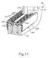
組織切断ワッシャ(240)は、アンビルプレート部分(212)の全長に沿って延在する一対の側部フランジ(252)を更に含む。図10及び図11に示すように、各側部フランジ(252)は、近位に延在して、アンビルプレート部分(212)のそれぞれの側縁部を覆い、かつ遠位に延在して、遠位支持構造体(48)を画定するそれぞれのサイドプレート(40)の遠位フック(47)の少なくとも一部分を覆う。したがって、有利なことに、側部フランジ(252)は、アンビルプレート部分(212)と遠位フック(47)との間に形成され得る軸方向の間隙(254)を覆うように機能し、それにより、組織に望ましくない外傷をもたらす可能性のある様式で、組織が軸方向の間隙(254)内に入り込み、挟まれることを防止することができる。図11に示すように、側部フランジ(252)の外側表面は、組織切断ワッシャ(240)の外周の非外傷性特性を更に向上させるために丸みを帯びていてもよい。組織切断ワッシャ(240)は、本願と同日出願の「Tissue Cutting Washer for Right Angle Surgical Stapler」と題する米国特許出願第[代理人参照番号END9086USNP1](その開示は参照により本明細書に組み込まれる)の教示のいずれかに従って更に構成されかつ動作可能であり得る。The tissue cutting washer (240) further includes a pair of side flanges (252) extending along the entire length of the anvil plate portion (212). As shown in FIGS. 10 and 11, each side flange (252) extends proximally to cover a respective side edge of the anvil plate portion (212) and extends distally to cover at least a portion of the distal hook (47) of a respective side plate (40) that defines the distal support structure (48). Thus, the side flanges (252) advantageously function to cover an axial gap (254) that may be formed between the anvil plate portion (212) and the distal hook (47), thereby preventing tissue from entering and becoming pinched within the axial gap (254) in a manner that may cause undesirable trauma to the tissue. As shown in FIG. 11, the outer surface of the side flange (252) may be rounded to further enhance the atraumatic properties of the circumference of the tissue-cutting washer (240). The tissue-cutting washer (240) may further be configured and operable in accordance with any of the teachings of U.S. Patent Application No. [Attorney Reference No. END9086USNP1], entitled "Tissue Cutting Washer for Right Angle Surgical Stapler," filed on even date herewith, the disclosure of which is incorporated herein by reference.
C.エンドエフェクタの遠位支持構造体へのステープルカートリッジユニットの例示的な装填
図9A及び図9Bは、エンドエフェクタ(16)の遠位支持構造体(48)への、新しい(又は「使用されていない」)状態のステープルカートリッジユニット(160)の装填を示す。図9Aに示すように、かつ上記で簡潔に記載したように、遠位支持構造体(48)は、遠位フック(47)によって画定される遠位側、遠位ジョー部分(46)の近位部分及び閉鎖バー(50)のカートリッジ受容遠位部分(52)の遠位端によって画定される近位側、及びそれらの間に配設された上方に開く軸方向の間隙を有するU字型の側面輪郭を有するように構成される。 C. Exemplary Loading of a Staple Cartridge Unit into a Distal Support Structure of an End Effector Figures 9A and 9B illustrate the loading of a staple cartridge unit (160) in a new (or "unused") state into the distal support structure (48) of an end effector (16). As shown in Figure 9A and as briefly described above, the distal support structure (48) is configured to have a U-shaped side profile having a distal side defined by a distal hook (47), a proximal side defined by a proximal portion of the distal jaw portion (46) and a distal end of the cartridge receiving distal portion (52) of the closure bar (50), and an upwardly opening axial gap disposed therebetween.
ステープルカートリッジユニット(160)には、図9A~図9Bに示すように、ステープルリテーナ(260)が設けられており、それは、デッキ(164)とアンビルプレート部分(212)との間に取り外し可能に位置付けられ、ステープル(170)をステープル開口部(168)内に保持し、ステープルカートリッジユニット(160)が遠位支持構造体(48)に挿入される際に、デッキ(164)とアンビルプレート部分(212)との間の適切な軸方向の間隔を確保する。ステープルリテーナ(260)は、本願と同日出願の「Staple Retainer for Right Angle Surgical Stapler」と題する米国特許出願第[代理人参照番号END9090USNP1](その開示は参照により本明細書に組み込まれる)の教示の少なくともいずれかに従って構成されかつ動作可能であり得る。ステープルリテーナ(260)を取り外すと、テープルカートリッジユニット(160)は、アンビルプレート部分(212)及び組織切断ワッシャ(240)によって画定される遠位側、カートリッジデッキ(164)によって画定される近位側、及びそれらの間に配設された上方に開く軸方向間隙(G)を有する、遠位支持構造体(48)と同様のU字型の側面輪郭を呈する。The staple cartridge unit (160) is provided with a staple retainer (260), as shown in FIGS. 9A-9B, which is removably positioned between the deck (164) and the anvil plate portion (212) to retain the staples (170) in the staple openings (168) and ensure proper axial spacing between the deck (164) and the anvil plate portion (212) when the staple cartridge unit (160) is inserted into the distal support structure (48). The staple retainer (260) may be constructed and operative in accordance with at least any of the teachings of U.S. Patent Application No. [Attorney Reference No. END9090USNP1], entitled "Staple Retainer for Right Angle Surgical Stapler," filed on even date herewith, the disclosure of which is incorporated herein by reference. With the staple retainer (260) removed, the staple cartridge unit (160) presents a U-shaped side profile similar to the distal support structure (48), with a distal side defined by the anvil plate portion (212) and the tissue cutting washer (240), a proximal side defined by the cartridge deck (164), and an upwardly opening axial gap (G) disposed therebetween.
図9Aに示すように、ユーザーはまず、カートリッジハウジング(162)の下部本体部分(184)上に形成された近位側レール(202)を、閉鎖バー(50)のカートリッジ受容遠位部分(52)に形成された内側チャネル(56)と位置合わせする(図3を参照)。図9Bに示すように、ユーザーは次に、カートリッジハウジング(162)の近位側レール(202)が閉鎖バー(50)の内側チャネル(56)内へ下方に摺動し、かつサイドプレート(40)の遠位フック(47)が組織切断ワッシャ本体(242)の遠位側に形成された溝に摺動するように(図11参照)、エンドエフェクタ(16)の遠位支持構造体(48)にステープルカートリッジユニット(160)を下方に押し込む。ステープルカートリッジユニット(160)が遠位支持構造体(48)内に完全に着座すると、カートリッジハウジング(162)の下部本体部分(184)上に形成された戻り止め突出部(204)は、閉鎖バー(50)のカートリッジ受容遠位部分(52)に形成されたそれぞれの開口部(58)内に受容され、それによって、ステープルカートリッジユニット(160)が遠位支持構造体(48)内に取り外し可能に固着される。開口部(58)とのカートリッジ戻り止め突出部(204)の係合は、ユーザーに触覚フィードバック及び/又は聴覚フィードバックを提供して、ステープルカートリッジユニット(160)が遠位支持構造体(48)内に完全に着座していることを確認することができる。As shown in FIG. 9A, the user first aligns the proximal rail (202) formed on the lower body portion (184) of the cartridge housing (162) with the inner channel (56) formed in the cartridge-receiving distal portion (52) of the closure bar (50) (see FIG. 3). As shown in FIG. 9B, the user then presses the staple cartridge unit (160) downwardly into the distal support structure (48) of the end effector (16) such that the proximal rail (202) of the cartridge housing (162) slides downwardly into the inner channel (56) of the closure bar (50) and the distal hook (47) of the side plate (40) slides into a groove formed distally in the tissue-cutting washer body (242) (see FIG. 11). When the staple cartridge unit (160) is fully seated within the distal support structure (48), the detent projections (204) formed on the lower body portion (184) of the cartridge housing (162) are received within respective openings (58) formed in the cartridge receiving distal portion (52) of the closure bar (50), thereby removably securing the staple cartridge unit (160) within the distal support structure (48). The engagement of the cartridge detent projections (204) with the openings (58) can provide tactile and/or audible feedback to a user to confirm that the staple cartridge unit (160) is fully seated within the distal support structure (48).
図9Aに示すように、遠位ロックアウトレバー(270)は、ステープルバー(60)の遠位端に枢動可能に連結される。遠位ロックアウトレバー(270)は、ステープルバー(60)及びナイフバー(70)の遠位縁部(64)に向かって遠位に延在し、サイドプレート(40)、閉鎖バー(50)、ステープルバー(60)、及びナイフバー(70)の遠位部分を通って横方向に延在する固定遠位ピン(280)と解放可能に係合するように構成されている。遠位ロックアウトレバー(270)は、未使用のステープルカートリッジユニット(160)の遠位支持構造体(48)への挿入時にステープルドライバ部材(186)の近位端が係合することに応じて、図9Aに示される上昇位置に向かって弾性的に付勢され、図9Bに示される下降位置に向かって枢動可能である。上昇位置において、遠位ロックアウトレバー(270)は固定遠位ピン(280)と係止されるように係合し、それによって、ステープルバー(60)及びナイフバー(70)の遠位作動を抑制し、ひいてはステープルカートリッジユニット(160)の発射を抑制する。下降位置において、遠位ロックアウトレバー(270)は固定遠位ピン(280)と係合解除され、それによって、ステープルカートリッジユニット(160)の発射のための、ステープルバー(60)及びナイフバー(70)の遠位作動を可能にする。遠位ロックアウトレバー(270)及び外科用ステープラ(10)の他のロックアウト特徴部は、本願と同日出願の「Cartridge Based Lockout Mechanism for Right Angle Surgical Stapler」と題する米国特許出願第[代理人参照番号END9088USNP1](その開示は参照により上記に組み込まれる)の教示のいずれかに従って更に構成されかつ動作可能であり得る。As shown in FIG. 9A, the distal lockout lever (270) is pivotally coupled to the distal end of the staple bar (60). The distal lockout lever (270) extends distally toward the distal edges (64) of the staple bar (60) and the knife bar (70) and is configured to releasably engage a fixed distal pin (280) that extends laterally through the distal portions of the side plate (40), the closure bar (50), the staple bar (60), and the knife bar (70). The distal lockout lever (270) is resiliently biased toward a raised position shown in FIG. 9A and pivotable toward a lowered position shown in FIG. 9B in response to engagement of the proximal end of the staple driver member (186) upon insertion of an unused staple cartridge unit (160) into the distal support structure (48). In the raised position, distal lockout lever (270) is locked in engagement with fixed distal pin (280), thereby inhibiting distal actuation of staple bar (60) and knife bar (70), and thus the firing of staple cartridge unit (160). In the lowered position, distal lockout lever (270) is disengaged from fixed distal pin (280), thereby allowing distal actuation of staple bar (60) and knife bar (70) for the firing of staple cartridge unit (160). The distal lockout lever (270) and other lockout features of the surgical stapler (10) may be further configured and operable in accordance with any of the teachings of U.S. Patent Application No. [Attorney Reference No. END9088USNP1], entitled "Cartridge Based Lockout Mechanism for Right Angle Surgical Stapler," filed on the same day herewith, the disclosure of which is incorporated herein by reference.
D.外科用ステープラの例示的な作動
ステープルカートリッジユニット(160)を含む、上記の外科用ステープラ(10)の様々な構造的特徴について記載してきたが、ここで外科手術中の外科用ステープラ(10)の例示的な作動について以下に記載する。未使用のステープルカートリッジユニット(160)を上記の様式で遠位支持構造体(48)に装填した後、次に患者の体腔内でエンドエフェクタ(16)を適切に操作して、アンビルプレート部分(212)とカートリッジデッキ(164)との間のステープルカートリッジ間隙(G)内に患者組織を位置付ける。図12A及び図12Bに示すように、次に、摺動部(34)を介して遠位に押棒(80)を作動させて、押棒(80)を遠位に駆動し、それによって、組織保持ピン(176)をカートリッジハウジング(162)から延在させて、その遠位先端部(178)を、カートリッジデッキ(164)の上端を覆う組織に貫通させて、アンビルプレート部分(212)の上端内に着座するようにする。このようにして、患者組織は、閉鎖前にカートリッジ間隙(G)内にしっかりと保持される。 D. Exemplary Operation of the Surgical Stapler Having described various structural features of the surgical stapler (10) above, including the staple cartridge unit (160), an exemplary operation of the surgical stapler (10) during a surgical procedure will now be described below. After an unused staple cartridge unit (160) is loaded into the distal support structure (48) in the manner described above, the end effector (16) is then appropriately manipulated within the patient's body cavity to position patient tissue within the staple cartridge gap (G) between the anvil plate portion (212) and the cartridge deck (164). 12A and 12B, the pusher rod (80) is then actuated distally via the slide (34) to drive the pusher rod (80) distally, thereby causing the tissue retaining pin (176) to extend from the cartridge housing (162) and penetrate its distal tip (178) through the tissue overlying the upper end of the cartridge deck (164) to seat within the upper end of the anvil plate portion (212). In this manner, the patient tissue is securely held within the cartridge gap (G) prior to closure.
図12Cに示すように、次いで、閉鎖トリガ(36)を介して遠位に閉鎖バー(50)を作動させて、それによって、カートリッジハウジング(162)を、ガイドピン(230)及び組織保持ピン(176)に沿って遠位に駆動して、カートリッジデッキ(164)とアンビル(212)との間に組織をクランプする。本実施例に示すように、ステープルバー(60)及びナイフバー(70)は、エンドエフェクタ(16)の完全閉鎖時にステープルドライバ部材(186)及びナイフ部材(194)が発射のために好適に位置付けられるように、閉鎖バー(50)及びカートリッジハウジング(162)とともに遠位に作動する。上述したように、エンドエフェクタ(16)は、ハンドル組立体(12)の解放ボタン(110)のロック爪(112)によって、完全閉鎖状態に解放可能に維持される。As shown in FIG. 12C, the closure bar (50) is then actuated distally via the closure trigger (36), thereby driving the cartridge housing (162) distally along the guide pins (230) and tissue retaining pins (176) to clamp the tissue between the cartridge deck (164) and the anvil (212). As shown in this embodiment, the staple bar (60) and knife bar (70) are actuated distally with the closure bar (50) and cartridge housing (162) such that the staple driver member (186) and knife member (194) are suitably positioned for firing upon full closure of the end effector (16). As described above, the end effector (16) is releasably maintained in the fully closed state by the locking pawl (112) of the release button (110) of the handle assembly (12).
図12Dに示すように、次に、ステープルバー(60)及びナイフバー(70)が発射トリガ(38)を介して遠位に作動され、それによって、ステープルドライバ部材(186)及びナイフバー(70)は、カートリッジハウジング(162)を通って遠位に駆動される。ステープルドライバ部材(186)のステープルドライバ要素(190)は、ステープル開口部(168)を通って遠位に前進し、それによって、その中に収容されたステープル(170)を、クランプされた組織を通って遠位に駆動し、アンビルプレート部分(212)のステープル形成ポケット(218)内に駆動し、ステープル(170)が組織内に形成されるようにする。ナイフ部材(194)は、ナイフ(198)を、カートリッジデッキ(164)の細長いナイフスロット(166)を通って、クランプされた組織を通って、かつ組織切断ワッシャ(240)の切断要素(244)に対して遠位に駆動させ、それによって、形成されたステープル(170)の最も内側の列の間の直線状切断線に沿ってクランプされた組織を切断する。クランプされた組織を完全に切断すると、ナイフの切断縁部(200)は、組織切断ワッシャー(240)の切断要素(244)内に遠位に貫通し得る。任意選択的に、このような貫通に応じて、組織切断ワッシャ本体(242)は、ナイフの切断縁部(200)に沿って破断することができ、それによって、発射ストロークが完了し、クランプされた組織が完全にステープル留めされ、かつ切断されたことを外科医に(例えば、「パチン」という音を介して)聴覚的に示すことができる。As shown in FIG. 12D, the staple bar (60) and knife bar (70) are then actuated distally via the firing trigger (38), thereby driving the staple driver member (186) and knife bar (70) distally through the cartridge housing (162). The staple driver elements (190) of the staple driver member (186) advance distally through the staple openings (168), thereby driving the staples (170) contained therein distally through the clamped tissue and into the staple forming pockets (218) of the anvil plate portion (212) such that the staples (170) are formed in the tissue. The knife member (194) drives the knife (198) through the elongated knife slot (166) of the cartridge deck (164), through the clamped tissue, and distally against the cutting element (244) of the tissue-cutting washer (240), thereby cutting the clamped tissue along a linear cut line between the innermost rows of formed staples (170). Upon fully cutting the clamped tissue, the knife cutting edge (200) may penetrate distally into the cutting element (244) of the tissue-cutting washer (240). Optionally, in response to such penetration, the tissue-cutting washer body (242) may break along the knife cutting edge (200), thereby providing an audible indication to the surgeon (e.g., via a "snap" sound) that the firing stroke is complete and the clamped tissue is fully stapled and cut.
上述したように、及び図12Dに示すように、発射トリガ(38)が組織のステープル留めすることになる最初の運動範囲を介して作動されると、ステープルドライバ部材(186)及びナイフ部材(194)は、ステープルカートリッジハウジング(162)を通って遠位に一緒に並進してもよい。図12Dに示すように、ナイフ部材(194)は、次に、発射トリガ(38)がステープル留めされた組織をナイフ(198)で切断することになる最終的な運動範囲を通して更に作動される際に、静止したステープルドライバ部材(186)に対して遠位に並進し続けてもよい。このようにして、エンドエフェクタ(16)によってクランプされた組織は、切断される前に完全にステープル留めされる。As described above and shown in FIG. 12D, the staple driver member (186) and the knife member (194) may translate distally together through the staple cartridge housing (162) as the firing trigger (38) is actuated through an initial range of motion that will staple the tissue. As shown in FIG. 12D, the knife member (194) may then continue to translate distally relative to the stationary staple driver member (186) as the firing trigger (38) is further actuated through a final range of motion that will cut the stapled tissue with the knife (198). In this manner, the tissue clamped by the end effector (16) is fully stapled before being cut.
図7に最も良く示すように、カートリッジハウジング(162)の下部本体部分(184)の第1の横方向の側面は、複数の軸方向に離間した凹部を有する戻り止めアーム(185)を含む。加えて、ステープルドライバ部材(186)の基部(188)の第1の横方向の側面は、横方向に延在する戻り止めポスト(189)を含むが、これは、クランプされた組織をステープル留めするときに、ステープルドライバ部材(186)が、カートリッジハウジング(162)を通って遠位に駆動される際に、戻り止めアーム(206)に沿って軸方向に戻り止めするように構成されている。図8に最も良く示すように、ステープルドライバ部材(186)の基部(188)の第2の横方向の側面は、複数の軸方向に離間した凹部を有する戻り止めアーム(191)を含む。加えて、ステープルドライバ部材(194)の基部(196)の第2の横方向の側面は、横方向に延在する戻り止めポスト(197)を含むが、これは、クランプされた組織を切断するときに、ナイフ部材(194)が、ステープルドライバ部材(186)を通って遠位に駆動される際に、戻り止めアーム(191)に沿って軸方向に戻り止めするように構成されている。このような戻り止め特徴部は、ステープルドライバ部材(186)が組織をステープル留めするために完全に伸張されたとき、及びその後、ナイフ部材(194)がステープル留めされた組織を切断するために完全に伸張されたときに、外科医に触覚フィードバックを提供することができる。As best shown in FIG. 7, a first lateral side of the lower body portion (184) of the cartridge housing (162) includes a detent arm (185) having a plurality of axially spaced recesses. In addition, a first lateral side of the base (188) of the staple driver member (186) includes a laterally extending detent post (189) that is configured to detent axially along the detent arm (206) as the staple driver member (186) is driven distally through the cartridge housing (162) when stapling the clamped tissue. As best shown in FIG. 8, a second lateral side of the base (188) of the staple driver member (186) includes a detent arm (191) having a plurality of axially spaced recesses. In addition, a second lateral side of the base (196) of the staple driver member (194) includes a laterally extending detent post (197) that is configured to detent axially along the detent arm (191) as the knife member (194) is driven distally through the staple driver member (186) when cutting the clamped tissue. Such a detent feature can provide tactile feedback to the surgeon when the staple driver member (186) is fully extended to staple the tissue, and thereafter when the knife member (194) is fully extended to cut the stapled tissue.
外科用ステープラ(10)が完全に発射されると、外科医は発射トリガ(38)を解放するが、これにより、ナイフバー(70)及びナイフ部材(194)を、上述のナイフ戻しばね(130)の弾性的な付勢を介して閉鎖バー(50)に対して近位に自動的に後退させることができる。本変形例では、閉鎖バー(50)に対するナイフバー(70)の近位後退はまた、閉鎖バー(50)に対するステープルバー(60)の近位後退をも駆動し、例えば、ナイフバー(70)の遠位部分上に形成された下部タブ(78)と、ステープルバー(60)の遠位部分の下面に形成された下部スロット(66)と、を係合することによって、ナイフバー(70)は、ステープルバー(60)と動作可能に連結される。一方、上記のステープル留め戻り止め特徴部(185、189)は、遠位ロックアウトレバー(270)がステープルドライバ部材(186)を係合解除するように、ステープルドライバ部材(186)をカートリッジハウジング(162)内のその完全に伸長した位置に維持するように動作する。これにより、遠位ロックアウトレバー(270)は、上昇したロックアウト位置に戻り、ステープルカートリッジユニット(160)が使用されたときに発射トリガ(38)の再作動を阻止することができる。このようにして、遠位ロックアウトレバー(270)は、ステープルを適用せずにナイフ(198)で組織を切断することとなる様式で、外科医が、使用済みステープルカートリッジユニット(160)を組織内に不注意に再発射することを防止する。Once the surgical stapler (10) is fully fired, the surgeon releases the firing trigger (38), which automatically retracts the knife bar (70) and knife member (194) proximally relative to the closure bar (50) via the resilient bias of the knife return spring (130) described above. In this variation, the proximal retraction of the knife bar (70) relative to the closure bar (50) also drives the proximal retraction of the staple bar (60) relative to the closure bar (50), and the knife bar (70) is operatively coupled to the staple bar (60), for example, by engaging a lower tab (78) formed on a distal portion of the knife bar (70) with a lower slot (66) formed in the underside of the distal portion of the staple bar (60). Meanwhile, the staple detent features (185, 189) described above operate to maintain the staple driver member (186) in its fully extended position within the cartridge housing (162) so that the distal lockout lever (270) disengages the staple driver member (186). This allows the distal lockout lever (270) to return to the raised, locked out position and prevent re-actuation of the firing trigger (38) when the staple cartridge unit (160) has been used. In this manner, the distal lockout lever (270) prevents the surgeon from inadvertently re-firing a used staple cartridge unit (160) into tissue in a manner that would result in the knife (198) cutting the tissue without applying staples.
発射トリガ(38)の解放後、次に外科医はハンドル組立体(12)上の解放ボタン(110)を押下して、上述した閉鎖復帰ばね(98)の弾性的な付勢を介して、閉鎖トリガ(36)及び閉鎖バー(50)がそれらの非作動状態に戻ることを可能にする。閉鎖バー(50)のこのような近位への後退は、ステープル留めされた組織及び切断された組織が、エンドエフェクタ(16)から解放され得るように、カートリッジハウジング(162)をアンビル(210)から近位に引き離す。閉鎖バー(50)の近位への後退はまた、ステープルバー(60)及びナイフバー(70)をそれらの近位ホーム位置よりも更に近位に後退することにより、使用済みステープルカートリッジユニット(160)を遠位支持構造体(48)から取り外し、新しいステープルカートリッジユニット(160)と交換することができる。After releasing the firing trigger (38), the surgeon then depresses the release button (110) on the handle assembly (12) to allow the closure trigger (36) and closure bar (50) to return to their unactuated state via the resilient bias of the closure return spring (98) described above. Such proximal retraction of the closure bar (50) draws the cartridge housing (162) proximally away from the anvil (210) so that the stapled and severed tissue may be released from the end effector (16). Proximal retraction of the closure bar (50) also retracts the staple bar (60) and knife bar (70) further proximally than their proximal home positions, thereby allowing the spent staple cartridge unit (160) to be removed from the distal support structure (48) and replaced with a new staple cartridge unit (160).
E.外科用ステープラの近位発射機構
場合によっては、外科手術中に閉鎖トリガ(36)を作動させて、エンドエフェクタ(16)内の組織をクランプしている間、操作者は、発射トリガ(38)上に指を不注意に静止させる可能性があり、又は発射トリガ(38)は、そうでなければ患者の身体の一部分に押し付けられる可能性がある。例えば、エンドエフェクタ(16)が組織上で部分的にのみ閉鎖されているときの発射システム(24)の早期作動は、組織内でステープル(170)の奇形をもたらし、組織がナイフ(198)によって切断されるときに不十分な止血を引き起こす可能性がある。上記で簡潔に記載したように、ハンドル組立体(12)の発射ロックアウトレバー(140)は、ステープル(170)及び切断線を適用する前に、エンドエフェクタ(16)が完全に閉鎖されて組織を適切にクランプするまで、発射トリガ(38)の枢動並びにステープルドライバ部材(186)及びナイフ部材(194)の結果の作動を抑制するように動作可能である。 E. Proximal Firing Mechanism of the Surgical Stapler In some cases, while actuating the closure trigger (36) to clamp tissue within the end effector (16) during a surgical procedure, an operator may inadvertently rest a finger on the firing trigger (38), or the firing trigger (38) may otherwise be pressed against a portion of the patient's body. For example, premature actuation of the firing system (24) when the end effector (16) is only partially closed on tissue may result in malformation of the staples (170) within the tissue, causing inadequate hemostasis as the tissue is severed by the knife (198). As briefly described above, the firing lockout lever (140) of the handle assembly (12) is operable to inhibit pivoting of the firing trigger (38) and resulting actuation of the staple driver member (186) and knife member (194) until the end effector (16) is fully closed to properly clamp tissue, prior to applying the staples (170) and cut line.
図13に示すように、かつ上記で簡潔に記載したように、発射ロックアウトレバー(140)は、枢動ピン(150)を介して、左のサイドプレート(40)の近位フレーム部分(42)の外側に枢動可能に取り付けられる。本変形例の発射ロックアウトレバー(140)は、いずれも近位フレーム部分(42)に平行な平面内に延在する上部アーム(144)及び上部アーム(144)の遠位端から下方に垂れ下がる下部脚部(148)を画定するL字状形状を有する。下部タブ(142)は、下側脚部(148)の下端から垂直に延在し、サイドプレート(40)の近位フレーム部分(42)に形成されたスロット(152)を通って発射トリガ(38)に向かって横方向内側に突出する。枢動ピン(150)は、上部アーム(144)の遠位端に位置付けられ、発射ロックアウトレバー(140)が、図14A及び図15Aに示されるロックアウト状態と図14B及び図15Bに示されるバイパス状態との間でサイドプレート(40)に対して枢動することを可能にする。伸張ばねの形態で示されるばね(146)は、近位端で近位フレーム部分(42)に、遠位端で下側脚部(148)に定着される。以下に記載されるように、ばね(146)は、発射ロックアウトレバー(140)をロックアウト状態に向かって弾性的に付勢するように動作可能である。As shown in FIG. 13 and briefly described above, the firing lockout lever (140) is pivotally mounted on the outside of the proximal frame portion (42) of the left side plate (40) via a pivot pin (150). The firing lockout lever (140) of this variation has an L-shaped configuration defining an upper arm (144) that both extend in a plane parallel to the proximal frame portion (42) and a lower leg (148) that depends downwardly from the distal end of the upper arm (144). A lower tab (142) extends perpendicularly from the lower end of the lower leg (148) and projects laterally inward toward the firing trigger (38) through a slot (152) formed in the proximal frame portion (42) of the side plate (40). A pivot pin (150) is positioned at the distal end of the upper arm (144) to allow the firing lockout lever (140) to pivot relative to the side plate (40) between a locked state, shown in FIGS. 14A and 15A, and a bypass state, shown in FIGS. 14B and 15B. A spring (146), shown in the form of an extension spring, is anchored at a proximal end to the proximal frame portion (42) and at a distal end to the lower leg (148). As described below, the spring (146) is operable to resiliently bias the firing lockout lever (140) toward the locked state.
図14A及び図15Aに示されるように、発射ロックアウトレバー(140)は、閉鎖システム(22)が、エンドエフェクタ(16)を完全に閉鎖するために完全な作動状態以外の任意の状態にある間、ロックアウト状態を呈する。ロックアウト状態では、発射ロックアウトレバー(140)の下部タブ(142)は、発射トリガ(38)の発射ロックアウト突起部(126)の横方向下に延在し、したがって、発射トリガ(38)が枢動して、上述のステープルバー(60)及びナイフバー(70)を作動させることを阻止する。発射ロックアウトレバー(140)は、エンドエフェクタ(16)を完全に閉鎖するまで、閉鎖システム(22)を介してエンドエフェクタ(16)の部分的閉鎖全体にわたってこのロックアウト状態を維持するように構成されている。As shown in Figures 14A and 15A, the firing lockout lever (140) assumes a locked state while the closure system (22) is in any state other than a fully actuated state to fully close the end effector (16). In the locked state, the lower tab (142) of the firing lockout lever (140) extends laterally below the firing lockout protrusion (126) of the firing trigger (38), thus preventing the firing trigger (38) from pivoting to actuate the staple bar (60) and knife bar (70) described above. The firing lockout lever (140) is configured to maintain this locked state throughout partial closure of the end effector (16) via the closure system (22) until the end effector (16) is fully closed.
図14Bに示すように、かつ上記で簡潔に説明したように、閉鎖トリガ(36)がピストルグリップ(32)に向かって握られて、閉鎖バー(50)を遠位に作動させ、それによってエンドエフェクタ(16)を閉鎖すると、解放ボタン(110)の爪状ラグ(114)は、閉鎖トリガ上部アーム(92)の上縁部を横切って摺動する。完全な作動状態に到達し、それによってエンドエフェクタ(16)を完全な閉鎖状態に配置すると、閉鎖トリガ(36)は回転配向され、その結果、爪状ラグ(114)が、解放ボタンばね(116)によって加えられた弾性付勢を介して、閉鎖トリガ上部アーム(92)内に形成された近位ノッチ(94)内に入り込む。ノッチ(94)内に入り込むと、爪状ラグ(114)は、ロックアウトレバー上部アーム(144)の近位端の上縁部に直接接触し、上部アーム(144)を下方に駆動する。図15Bに示されるように、この係合は、ロックアウトレバー(140)を枢動ピン(150)の周りで時計回りに枢動させ、その結果、下部タブ(142)がスロット(152)内で、発射トリガ突起部(126)の下面の下から外へと遠位に前進する。図14Cに示すように、次いで、発射トリガ(38)をピストルグリップ(32)に向かって作動させて、ステープルバー(60)及びナイフバー(70)を遠位に作動させ、エンドエフェクタ(16)を発射することができる。As shown in FIG. 14B and briefly described above, when the closure trigger (36) is squeezed toward the pistol grip (32) to actuate the closure bar (50) distally, thereby closing the end effector (16), the pawl-like lug (114) of the release button (110) slides across the upper edge of the closure trigger upper arm (92). Upon reaching a fully actuated state, thereby placing the end effector (16) in a fully closed state, the closure trigger (36) is rotationally oriented such that the pawl-like lug (114) enters into a proximal notch (94) formed in the closure trigger upper arm (92) via a resilient bias applied by the release button spring (116). Once in the notch (94), the pawl-like lug (114) comes into direct contact with the upper edge of the proximal end of the lockout lever upper arm (144) and drives the upper arm (144) downward. As shown in FIG. 15B, this engagement causes the lockout lever (140) to pivot clockwise about the pivot pin (150), causing the lower tab (142) to advance distally within the slot (152) and out from beneath the underside of the firing trigger projection (126). As shown in FIG. 14C, the firing trigger (38) can then be actuated toward the pistol grip (32) to actuate the staple bar (60) and knife bar (70) distally and fire the end effector (16).
上述のように、エンドエフェクタ(16)が組織内に発射された後、発射トリガ(38)は、操作者によって解放されると、非作動状態に弾性的に戻る。次いで、操作者は解放ボタン(110)を押下して、爪状ラグ(114)を閉鎖トリガ(36)の近位ノッチ(94)から上昇させ、それによって、閉鎖トリガ(36)が非作動状態に弾性的に戻ることを可能にすることができる。近位ノッチ(94)から上昇すると、爪状ラグ(114)は、発射ロックアウトレバー(140)の上部アーム(144)を係合解除し、したがって、ロックアウトレバー(140)がばね(146)の弾性付勢によってロックアウト状態に戻ることを可能にする。したがって、ロックアウトレバー(140)は、閉鎖トリガ(36)が再び完全に作動してエンドエフェクタ(16)を完全に閉鎖するまで、発射トリガ(38)の再作動を防止する。しかしながら、エンドエフェクタ(16)が再び完全に閉鎖されて、バイパス状態で近位発射ロックアウトレバー(140)を提供する場合であっても、使用済みステープルカートリッジユニット(160)の再発射は、遠位ロックアウトレバー(140)によって防止され得る(図9A~9B参照)。上述のように、遠位ロックアウトレバー(140)は、本願と同日出願の「Cartridge Based Lockout Mechanism for Right Angle Surgical Stapler」と題する米国特許出願第[代理人参照番号END9088USNP1](その開示は参照により上記に組み込まれる)の教示のいずれかに従って更に構成されかつ動作可能であり得る。As described above, after the end effector (16) is fired into tissue, the firing trigger (38) resiliently returns to its inactivated state when released by the operator. The operator can then depress the release button (110) to cause the pawl lug (114) to rise from the proximal notch (94) of the closure trigger (36), thereby allowing the closure trigger (36) to resiliently return to its inactivated state. Upon rising from the proximal notch (94), the pawl lug (114) disengages the upper arm (144) of the firing lockout lever (140), thus allowing the lockout lever (140) to return to its locked state by the resilient bias of the spring (146). The lockout lever (140) thus prevents re-actuation of the firing trigger (38) until the closure trigger (36) is again fully actuated to fully close the end effector (16). However, even if the end effector (16) is again fully closed to provide the proximal firing lockout lever (140) in a bypass state, re-firing of the spent staple cartridge unit (160) can be prevented by the distal lockout lever (140) (see FIGS. 9A-9B). As mentioned above, the distal lockout lever (140) can be further configured and operable in accordance with any of the teachings of U.S. Patent Application No. [Attorney Reference No. END9088USNP1] entitled "Cartridge Based Lockout Mechanism for Right Angle Surgical Stapler" filed on the same day herewith (the disclosure of which is incorporated by reference above).
図16は、上述の発射ロックアウトレバー(140)の代わりに外科用ステープラ(10)とともに使用するのに好適な例示的な代替の発射ロックアウトレバー(290)を示すが、これは、以下に別途記載される点を除き、発射ロックアウトレバー(140)と同様である。発射ロックアウトレバー(290)は、上部アーム(292)と、上部アーム(292)の遠位端から下方に垂れ下がってL字状形状を画定する遠位脚部(294)と、遠位脚部(294)の下端から横方向内側に延在する下部タブ(296)と、を含む。発射ロックアウトレバー(290)は、下方に垂れ下がり、上方アーム(292)の近位端を形成する近位脚部(298)を更に含む。近位脚部(298)の下端は、上述のばね(146)と同様に、発射ロックアウトレバー(290)をロックアウト位置に向かって弾性的に付勢する戻しばね(図示せず)と連結するように構成されている。したがって、戻りばねは、遠位脚部(294)ではなく近位脚部(298)に連結されるが、これは、場合によっては有利であり得る構成を提供する。16 illustrates an exemplary alternative firing lockout lever (290) suitable for use with the surgical stapler (10) in place of the firing lockout lever (140) described above, which is similar to the firing lockout lever (140) except as otherwise described below. The firing lockout lever (290) includes an upper arm (292), a distal leg (294) depending downwardly from a distal end of the upper arm (292) to define an L-shaped configuration, and a lower tab (296) extending laterally inwardly from a lower end of the distal leg (294). The firing lockout lever (290) further includes a proximal leg (298) depending downwardly and forming a proximal end of the upper arm (292). The lower end of the proximal leg (298) is configured to couple with a return spring (not shown) that resiliently biases the firing lockout lever (290) toward a locked position, similar to the spring (146) described above. Thus, the return spring is coupled to the proximal leg (298) rather than the distal leg (294), providing a configuration that may be advantageous in some cases.
ロックアウトレバー(290)は、それ以外の点ではロックアウトレバー(140)と機能的に同様である。具体的には、ロックアウトレバー(290)は、下部タブ(296)が発射トリガ(38)の突出部(126)の下にあり、したがって発射トリガ(38)の作動を抑制するロックアウト位置と、下部タブ(296)が発射トリガ突出部(126)から離れるように移動し、したがって発射トリガ(38)の作動を可能にするバイパス位置と、の間で枢動点(299)を中心に枢動するように構成されている。ロックアウトレバー(290)のそのような作動は、エンドエフェクタ(16)を組織上に完全にクランプするための閉鎖トリガ(36)の完全な作動に応答して、解放ボタン(110)の爪状ラグ(114)によって駆動される。The lockout lever (290) is otherwise functionally similar to the lockout lever (140). Specifically, the lockout lever (290) is configured to pivot about a pivot point (299) between a locked position in which the lower tab (296) is below the projection (126) of the firing trigger (38), thus inhibiting actuation of the firing trigger (38), and a bypass position in which the lower tab (296) moves away from the firing trigger projection (126), thus allowing actuation of the firing trigger (38). Such actuation of the lockout lever (290) is driven by the pawl-like lug (114) of the release button (110) in response to full actuation of the closure trigger (36) to fully clamp the end effector (16) on tissue.
II.例示的な代替の発射ロックアウト機構
場合によっては、上述の発射ロックアウト機構(140)と構造が異なるが、同様の機能を行う発射ロックアウト機構を備えた外科用ステープラ(10)を提供することが望ましい場合がある。以下に記載される例示的な代替の発射ロックアウト機構(360、440)は、発射ロックアウト機構(140)と機能的に同様である。その点に関し、各ロックアウト機構(360、440)は、エンドエフェクタが完全に閉鎖されていない限り、発射システムの作動を抑制するように動作可能であり、したがって、患者組織内のステープルの奇形及び結果として得られる不十分な止血から保護する。上述のロックアウト機構(140)と同様に、以下に記載される各ロックアウト機構(360、440)は、発射トリガの作動を抑制するロックアウト状態に向かって弾性的に付勢され、エンドエフェクタを完全に閉鎖するための閉鎖トリガの完全な作動に応答して、発射システムの作動を可能にするバイパス状態に移行するように構成されている。 II. Exemplary Alternative Firing Lockout Mechanisms In some cases, it may be desirable to provide a surgical stapler (10) with a firing lockout mechanism that is structurally different from, but performs a similar function to, the above-described firing lockout mechanism (140). The exemplary alternative firing lockout mechanisms (360, 440) described below are functionally similar to the firing lockout mechanism (140). In that regard, each lockout mechanism (360, 440) is operable to inhibit actuation of the firing system unless the end effector is fully closed, thus protecting against staple malformation within the patient tissue and resulting in inadequate hemostasis. As with the lockout mechanism (140) described above, each lockout mechanism (360, 440) described below is configured to be resiliently biased toward a locked state that inhibits actuation of the firing trigger and transition to a bypass state that allows actuation of the firing system in response to full actuation of the closure trigger to fully close the end effector.
A.並進可能部材を有する発射ロックアウト機構
図17は、以下に別途記載する点を除き、上述の直角直線状外科用ステープラ(10)と同様である別の例示的な直角直線状外科用ステープラ(310)の近位部分を示す。外科用ステープラ(10)と同様に、外科用ステープラ(310)は、ハンドル組立体(312)と、ハンドル組立体(312)から遠位に延在するシャフト組立体(314)と、シャフト組立体(314)の遠位端にあるエンドエフェクタ(16)と、を含む。ハンドル組立体(312)は、ハンドルハウジング(330)と、ピストルグリップ(332)と、閉鎖トリガ(336)と、発射トリガ(338)と、近位解放ボタン(350)と、を含む。一対の長手方向に延在するものは、組織保持ピン作動システム(320)、閉鎖システム(322)、及び発射システム(324)を支持するステープラ(310)のフレーム構造体を画定するように協働する。各サイドプレート(340)は、近位フレーム部分(342)と、内側シャフト部分(344)と、遠位ジョー部分(46)と同様の遠位ジョー部分(図示せず)と、を含む。 A. Firing Lockout Mechanism with Translatable Member Figure 17 illustrates a proximal portion of another exemplary right angle linear surgical stapler (310), which is similar to the right angle linear surgical stapler (10) described above, except as otherwise described below. Like the surgical stapler (10), the surgical stapler (310) includes a handle assembly (312), a shaft assembly (314) extending distally from the handle assembly (312), and an end effector (16) at the distal end of the shaft assembly (314). The handle assembly (312) includes a handle housing (330), a pistol grip (332), a closure trigger (336), a firing trigger (338), and a proximal release button (350). The pair of longitudinally extending ones cooperate to define a frame structure of the stapler (310) that supports the tissue retaining pin actuation system (320), the closure system (322), and the firing system (324). Each side plate (340) includes a proximal frame portion (342), an inner shaft portion (344), and a distal jaw portion (not shown) similar to distal jaw portion (46).
外科用ステープラ(310)は、並進可能なロックアウトプレート(362)と、左のサイドプレート(340)の近位フレーム部分(342)に移動可能に取り付けられた並進可能なロックアウトピン(370)と、を含む近位発射ロックアウト機構(360)と、近位フレーム部分(342)から外側に延在する一対の傾斜面(380)と、を含む。ロックアウトプレート(362)は、自由な上端(364)を有する細長い本体、下端に形成された細長いスロット(366)、及び上端部(364)と細長いスロット(366)との間に配設された一対の外向きに延在するショルダ(368)を備える細長い本体を有する。ロックアウトプレート(362)は、サイドプレート(340)の近位フレーム部分(342)に平行な平面内に延在し、並進する。ロックアウトピン(370)は、ロックアウトプレート(362)に対して横切るように延在し、ピンヘッド(372)と、ピンシャフト(374)と、を含む。ピンシャフト(374)は、ロックアウトプレート(362)の細長いスロット(366)及びサイドプレート(340)の近位フレーム部分(342)内に形成された対応する開口部(343)(図19Bを参照)を通って、発射トリガ(338)に向かう方向に、横方向に延在する。ピンヘッド(372)は、細長いスロット(366)を取り囲むロックアウトプレート(362)の外側表面に摺動可能に当接するように構成されている。本変形例では、一対の傾斜面(380)は、サイドプレート(340)の近位フレーム部分(342)から横方向外側に突出し、細長いスロット(366)が配設されるロックアウトプレート(362)の下部のいずれかの側に位置付けられている。他の変形例では、傾斜面(380)は、ロックアウトプレート(362)の構造体、例えば細長いスロット(366)のいずれかの側に一体化されてもよい。The surgical stapler (310) includes a proximal firing lockout mechanism (360) including a translatable lockout plate (362), a translatable lockout pin (370) movably mounted to the proximal frame portion (342) of the left side plate (340), and a pair of ramps (380) extending outwardly from the proximal frame portion (342). The lockout plate (362) has an elongated body with a free upper end (364), an elongated slot (366) formed at the lower end, and a pair of outwardly extending shoulders (368) disposed between the upper end (364) and the elongated slot (366). The lockout plate (362) extends and translates in a plane parallel to the proximal frame portion (342) of the side plate (340). The lockout pin (370) extends transversely relative to the lockout plate (362) and includes a pin head (372) and a pin shaft (374). The pin shaft (374) extends laterally through an elongated slot (366) of the lockout plate (362) and a corresponding opening (343) (see FIG. 19B) formed in the proximal frame portion (342) of the side plate (340) in a direction toward the firing trigger (338). The pin head (372) is configured to slidably abut an outer surface of the lockout plate (362) surrounding the elongated slot (366). In this variation, a pair of angled surfaces (380) protrude laterally outward from the proximal frame portion (342) of the side plate (340) and are positioned on either side of a lower portion of the lockout plate (362) in which the elongated slot (366) is disposed. In other variations, the ramp (380) may be integrated into the structure of the lockout plate (362), such as on either side of the elongated slot (366).
図18A~図19Bに関連して以下に記載するように、並進可能なロックアウトプレート(362)及び並進可能なロックアウトピン(370)は、傾斜面(380)と協働して、ピン(370)が発射トリガ(338)の作動を阻止するロックアウト状態とピン(370)が発射トリガ(338)の作動を可能にするバイパス状態との間で、ロックアウト機構(360)を移行させるように構成されている。ロックアウト状態とバイパス状態との間を移行する際、ロックアウトプレート(362)は、サイドプレート(340)に平行に延在する第1の軸に沿って並進するように構成され、ロックアウトピン(370)は、第1の軸に対して横切るように延在する横方向の軸に沿って並進するように構成されている。上述の発射ロックアウトレバー(140、290)と同様に、ロックアウトプレート(362)及びロックアウトピン(370)は、1つ又は2つ以上の弾性部材(図示せず)によってロックアウト状態に向かって弾性的に付勢される。18A-19B, the translatable lockout plate (362) and the translatable lockout pin (370) are configured to cooperate with the ramp (380) to transition the lockout mechanism (360) between a locked state in which the pin (370) prevents actuation of the firing trigger (338) and a bypass state in which the pin (370) allows actuation of the firing trigger (338). When transitioning between the locked state and the bypass state, the lockout plate (362) is configured to translate along a first axis extending parallel to the side plate (340), and the lockout pin (370) is configured to translate along a lateral axis extending transversely to the first axis. As with the firing lockout levers (140, 290) described above, the lockout plate (362) and the lockout pin (370) are resiliently biased toward the locked state by one or more resilient members (not shown).
図18A及び図19Aは、ロックアウト機構(360)が、閉鎖トリガ(336)が完全に作動していない任意の状態にあるときに、維持するように構成されているロックアウト状態にある発射ロックアウト機構(360)を示す。その点に関し、発射ロックアウト機構(360)は、エンドエフェクタの完全な閉鎖まで、閉鎖トリガ(336)の部分的な作動及び結果として得られるエンドエフェクタの部分的閉鎖の全体にわたってロックアウト状態を維持するように構成されている。ロックアウト状態において、ロックアウトプレート(362)は上昇位置にあり、その結果、ロックアウトピン(370)が細長いスロット(366)の下端に配設される。したがって、図19Aに示すように、ピン(370)は、ピンシャフト(374)が発射トリガ(338)の遠位突出部(339)の下面の下に位置付けられ、したがって、発射トリガ(338)が作動してエンドエフェクタを発射することを阻止する横方向内側位置を呈する。18A and 19A show the firing lockout mechanism (360) in a locked state that the lockout mechanism (360) is configured to maintain when the closure trigger (336) is in any state where the closure trigger (336) is not fully actuated. In that regard, the firing lockout mechanism (360) is configured to maintain the locked state throughout partial actuation of the closure trigger (336) and the resulting partial closure of the end effector until the end effector is fully closed. In the locked state, the lockout plate (362) is in a raised position such that the lockout pin (370) is disposed at the lower end of the elongated slot (366). Thus, as shown in FIG. 19A, the pin (370) assumes a lateral inward position in which the pin shaft (374) is positioned below the lower surface of the distal projection (339) of the firing trigger (338) and thus prevents the firing trigger (338) from being actuated to fire the end effector.
図18Bに示すように、エンドエフェクタを完全に閉鎖するための閉鎖トリガ(336)の完全な作動は、閉鎖トリガ(36)のノッチ(94)と同様に、閉鎖トリガ(336)の上部ノッチ(図示せず)を解放ボタン(350)の爪状ラグ(352)と回転位置合わせする。解放ボタンばね(356)によって提供される弾性付勢を介して、爪状ラグ(352)は、閉鎖トリガ(336)の上部ノッチ内に入り込み、閉鎖トリガ(336)を完全な作動位置にロックする。爪状ラグ(352)のこの下向きの運動は、遠位ラグ伸張部(354)をロックアウトプレート(362)の上端(364)に係合させ、したがって、ロックアウトプレート(362)を、サイドプレート(340)に沿って下向きかつ遠位に、下降プレート位置まで並進させる。ロックアウトピン(370)はロックアウトプレート(362)の並進軸に沿って固定されるため、ピン(370)は細長いスロット(366)の上側近位端に前進する。同時に、図19Bで最も良く分かるように、プレートショルダ(368)は傾斜面(380)に沿って下向きかつ遠位に前進し、これによってロックアウトプレート(362)をサイドプレート(340)から横方向に離れるように駆動する。次に、ロックアウトプレート(362)は、ピンヘッド(372)を介して、ロックアウトピン(370)を発射トリガ(338)から横方向に引き離し、したがって、バイパス状態にあるロックアウト機構(360)を提供する。図19Bに示すように、発射トリガ突起部(339)の下面からピンシャフト(374)が引き抜かれ、その結果、発射トリガ(338)がエンドエフェクタを発射するためにピストルグリップ(332)に向かって自由に作動する。As shown in FIG. 18B, full actuation of the closure trigger (336) to fully close the end effector rotates the upper notch (not shown) of the closure trigger (336) into rotational alignment with the pawl lug (352) of the release button (350), as well as the notch (94) of the closure trigger (36). Through a resilient bias provided by the release button spring (356), the pawl lug (352) slides into the upper notch of the closure trigger (336), locking the closure trigger (336) in the fully actuated position. This downward movement of the pawl lug (352) engages the distal lug extension (354) with the upper end (364) of the lockout plate (362), thus translating the lockout plate (362) downward and distally along the side plate (340) to the lowered plate position. As the lockout pin (370) is fixed along the translation axis of the lockout plate (362), the pin (370) advances to the upper proximal end of the elongated slot (366). At the same time, as best seen in FIG. 19B, the plate shoulder (368) advances downward and distally along the inclined surface (380), thereby driving the lockout plate (362) laterally away from the side plate (340). The lockout plate (362) then pulls the lockout pin (370) laterally away from the firing trigger (338) via the pin head (372), thus providing the lockout mechanism (360) in a bypass state. As shown in FIG. 19B, the pin shaft (374) is withdrawn from the underside of the firing trigger protrusion (339), so that the firing trigger (338) is free to actuate toward the pistol grip (332) to fire the end effector.
操作者が解放ボタン(350)を作動させると、爪状ラグ(352)は閉鎖トリガ(336)の上部ノッチを係合解除し、したがって、閉鎖トリガ(336)が、エンドエフェクタから組織を解放するための非作動状態に枢動可能に戻ることを可能にする。同時に、ラグ伸張部(354)は、ロックアウトプレート(362)の上端(364)上でその下向きの力を解放する。弾性付勢を介して、ロックアウトプレート(362)は上向きに並進して上昇プレート位置に戻り、その結果、プレートショルダ(368)が傾斜面を係合解除し、したがって、ロックアウトプレート(362)が上昇位置を再び呈する際に、ロックアウトプレート(362)がサイドプレート(340)に向かって横方向に引き込まれることを可能にする。結果として、弾性付勢を介して、ロックアウトピン(370)は、スロット(366)及び開口部(343)を通って横方向内向きに並進して、発射トリガ突起部(339)を再係合し、したがってロックアウト機構(360)をロックアウト状態に戻す。When the operator actuates the release button (350), the pawl-like lug (352) disengages the upper notch of the closure trigger (336), thus allowing the closure trigger (336) to pivotally return to an inactivated state for releasing tissue from the end effector. At the same time, the lug extension (354) releases its downward force on the upper end (364) of the lockout plate (362). Through a resilient bias, the lockout plate (362) translates upwardly back to the raised plate position, so that the plate shoulder (368) disengages the ramp, thus allowing the lockout plate (362) to be retracted laterally toward the side plate (340) as the lockout plate (362) resumes its raised position. As a result, through resilient bias, the lockout pin (370) translates laterally inward through the slot (366) and opening (343) to re-engage the firing trigger protrusion (339), thus returning the lockout mechanism (360) to the locked state.
B.発射バーを係合するように構成された発射ロックアウト機構
図20A~20Bは、上述のステープラ(10、310)と同様の直角直線状外科用ステープラであってもよい、別の例示的な外科用ステープラ(410)のハンドル組立体(412)の選択構成要素の部分を示す。ハンドル組立体(412)は、枢動可能な閉鎖トリガ(414)と、閉鎖トリガ(414)の遠位に配置された枢動可能な発射トリガ(416)と、解放ボタン(420)と、を含む。細長い発射バー(430)は、ハンドル組立体(412)から遠位に延在し、発射トリガ(416)によって遠位側に作動して、上述のエンドエフェクタ(16)と同様であってもよいステープラ(410)のエンドエフェクタ(図示せず)を発射するように構成されている。発射バー(430)の近位端は、以下に記載される発射ロックアウト機構(430)によって係合されるように構成された垂直スロット(432)を含む。発射バー(430)は、ステープルバー(60)と同様のステープルバー、ナイフバー(70)と同様のナイフバー、又はその両方を含んでもよい。 B. Firing Lockout Mechanism Configured to Engage a Firing Bar Figures 20A-20B show portions of select components of a handle assembly (412) of another exemplary surgical stapler (410), which may be a right-angle linear surgical stapler similar to the staplers (10, 310) described above. The handle assembly (412) includes a pivotable closure trigger (414), a pivotable firing trigger (416) disposed distally of the closure trigger (414), and a release button (420). An elongated firing bar (430) extends distally from the handle assembly (412) and is configured to be actuated distally by the firing trigger (416) to fire an end effector (not shown) of the stapler (410), which may be similar to the end effector (16) described above. The proximal end of the firing bar (430) includes a vertical slot (432) configured to be engaged by a firing lockout mechanism (430) described below. Firing bar (430) may include a staple bar, similar to staple bar (60), a knife bar, similar to knife bar (70), or both.
外科用ステープラ(410)の発射ロックアウト機構(430)は、枢動可能なロックアウトレバーの形態で示される。ロックアウトレバー(440)は、近位端(442)と横方向の突出部(446)を有する遠位端(444)との間で長手方向に延在し、枢動ピン(448)によって画定される横方向の軸を中心に枢動するように構成されている。図20A~20Bに示されるように、ロックアウトレバー(440)は、ロックアウトレバー(440)が発射バー(430)の作動を抑制するロックアウト状態と、ロックアウトレバー(440)が発射バー(430)の作動を可能にするバイパス状態との間で枢動するように構成されている。The firing lockout mechanism (430) of the surgical stapler (410) is shown in the form of a pivotable lockout lever. The lockout lever (440) extends longitudinally between a proximal end (442) and a distal end (444) having a lateral projection (446) and is configured to pivot about a lateral axis defined by a pivot pin (448). As shown in FIGS. 20A-20B, the lockout lever (440) is configured to pivot between a locked state in which the lockout lever (440) inhibits actuation of the firing bar (430) and a bypass state in which the lockout lever (440) allows actuation of the firing bar (430).
図20Aに示されるロックアウト状態では、遠位レバー端部(444)は下向きに位置付けられ、その結果、横方向の突出部(446)は、発射バー(430)の垂直スロット(432)内に受容される。横方向の突出部(446)と垂直スロット(432)との間のこの係合は、発射トリガ(416)による発射バー(430)の長手方向の作動及び結果として得られるエンドエフェクタの発射を抑制する。ロックアウトレバー(440)による発射バー(430)のそのような長手方向のロックは、発射トリガ(416)の作動を効果的に抑制することが理解されるであろう。したがって、発射バー(430)がステープルバーと、ナイフバーと、を含む変形例では、そのようなバーのいずれかがロックアウトレバー(440)によって係合されて、発射トリガ(416)の作動及び結果として得られるエンドエフェクタの発射を抑制することができる。ロックアウトレバー(440)は、伸張ばね(450)の形態で示される弾性部材によってロックアウト状態に向かって弾性的に付勢され、弾性部材は、ロックアウトレバー(440)の一部分に枢動ピン(448)の遠位に連結される。したがって、ロックアウトレバー(440)は、図20Aに示すように、閉鎖トリガ(414)が非作動状態又は任意の部分的な作動状態にある間、ロックアウト状態を維持するように構成されている。In the locked out state shown in FIG. 20A, the distal lever end (444) is positioned downwardly such that the lateral projection (446) is received within the vertical slot (432) of the firing bar (430). This engagement between the lateral projection (446) and the vertical slot (432) inhibits longitudinal actuation of the firing bar (430) by the firing trigger (416) and the resulting firing of the end effector. It will be appreciated that such longitudinal locking of the firing bar (430) by the lockout lever (440) effectively inhibits actuation of the firing trigger (416). Thus, in variations in which the firing bar (430) includes a staple bar and a knife bar, either of such bars can be engaged by the lockout lever (440) to inhibit actuation of the firing trigger (416) and the resulting firing of the end effector. The lockout lever (440) is resiliently biased toward the locked state by a resilient member, shown in the form of an extension spring (450), which is coupled to a portion of the lockout lever (440) distal to the pivot pin (448). Thus, the lockout lever (440) is configured to remain in the locked state while the closure trigger (414) is in an unactuated state or any partially actuated state, as shown in FIG. 20A.
図20Bに示すように、外科用ステープラ(410)のエンドエフェクタを完全に閉鎖するための閉鎖トリガ(414)の完全な作動は、閉鎖トリガ(414)の近位上部ノッチ(415)を解放ボタン(420)のロック爪(422)と回転位置合わせする。解放ボタンばね(図示せず)によって提供される弾力的な付勢の下で、ロック爪(422)は、ノッチ(415)内へと下方に入り込み、それによって閉鎖トリガ(414)を完全な作動状態でロックして、エンドエフェクタを完全な閉鎖状態に維持する。同時に、解放ボタン(420)の遠位伸張部(424)は、近位レバー端部(442)と係合して、近位レバー端部(442)を下方に駆動し、ロックアウトレバー(440)を枢動ピン(448)の周りで枢動させ、その結果、遠位レバー端部(444)が上昇し、それによって横方向の突出部(446)を発射バー(430)の垂直スロット(432)から係合解除する。したがって、発射バー(430)はここで、エンドエフェクタを発射するための発射トリガ(416)の作動に応答して、遠位に自由に並進する。エンドエフェクタの発射後、発射バー(430)は、図20Aに示されるそのホーム位置まで近位に後退し、解放ボタン(420)は外科医によって押下され、ロック爪(422)を閉鎖トリガ(414)から係合解除し、したがって、閉鎖トリガ(414)が非作動位置に戻ることを可能にする。同時に、遠位伸張部(424)は近位レバー端部(442)を係合解除し、したがって、ロックアウトレバー(440)が反時計回りに枢動し、その結果、遠位レバー端部(444)が発射バー(430)と再係合してロックアウト状態を再確立する。As shown in FIG. 20B, full actuation of the closure trigger (414) to fully close the end effector of the surgical stapler (410) rotates the proximal upper notch (415) of the closure trigger (414) into rotational alignment with the locking pawl (422) of the release button (420). Under a resilient bias provided by a release button spring (not shown), the locking pawl (422) slides downwardly into the notch (415), thereby locking the closure trigger (414) in the fully actuated state and maintaining the end effector in the fully closed state. At the same time, the distal extension (424) of the release button (420) engages the proximal lever end (442) driving it downward and pivoting the lockout lever (440) about the pivot pin (448) such that the distal lever end (444) rises, thereby disengaging the lateral projection (446) from the vertical slot (432) of the firing bar (430). Thus, the firing bar (430) is now free to translate distally in response to actuation of the firing trigger (416) to fire the end effector. After firing of the end effector, the firing bar (430) retracts proximally to its home position shown in FIG. 20A and the release button (420) is depressed by the surgeon to disengage the locking pawl (422) from the closure trigger (414), thus allowing the closure trigger (414) to return to its unactuated position. At the same time, the distal extension (424) disengages the proximal lever end (442), thus causing the lockout lever (440) to pivot counterclockwise, thereby causing the distal lever end (444) to re-engage with the firing bar (430) to re-establish the locked out condition.
III.例示的な組み合わせ
以下の実施例は、本明細書の教示を組み合わせるか又は適用することができる、様々な非網羅的な方法に関する。以下の実施例は、本出願における又は本出願の後の書類提出におけるどの時点でも提示され得る、いずれの請求項の適用範囲をも限定することを目的としたものではないと理解されよう。一切の権利放棄を意図するものではない。以下の実施例は、単なる例示の目的で与えられるものに過ぎない。本明細書の様々な教示は、他の多くの方法で構成及び適用が可能であると考えられる。また、いくつかの変形では、以下の実施例において言及される特定の特徴部を省略してよいことも考えられる。したがって、本発明者又は本発明者の利益の継承者により、後日、そうである旨が明示的に示されない限り、以下に言及される態様又は特徴部のいずれも重要なものとしてみなされるべきではない。以下に言及される特徴部以外の更なる特徴部を含む請求項が本出願において、又は本出願に関連する後の書類提出において示される場合、それらの更なる特徴部は、特許性に関連するいかなる理由によっても追加されたものとして仮定されるべきではない。 III. EXEMPLARY COMBINATIONS The following examples relate to various non-exhaustive ways in which the teachings herein may be combined or applied. It will be understood that the following examples are not intended to limit the scope of any claims that may be presented at any time in this application or in a later filing of this application. No disclaimer is intended. The following examples are provided for illustrative purposes only. It is contemplated that the various teachings herein may be configured and applied in many other ways. It is also contemplated that certain features referred to in the following examples may be omitted in some variations. Thus, none of the aspects or features referred to below should be considered as critical unless expressly indicated to be so at a later date by the inventor or the inventor's successor in interest. If a claim including additional features other than those referred to below is presented in this application or in a later filing related to this application, those additional features should not be presumed to have been added for any reason related to patentability.
外科用ステープラであって、(a)本体と、(b)本体から遠位に延在するシャフト組立体と、(c)シャフト組立体の遠位端にあるエンドエフェクタであって、組織を受容するための開放状態と組織をクランプするための閉鎖状態との間で作動可能である、エンドエフェクタと、(d)エンドエフェクタと動作可能に連結された閉鎖システムであって、エンドエフェクタを開放状態から閉鎖状態に作動させるように動作可能である、閉鎖システムと、(e)エンドエフェクタと動作可能に連結された発射システムであって、エンドエフェクタを閉鎖状態で作動させて、クランプされた組織をステープル留めするように動作可能である、発射システムと、(f)発射システムと動作可能に連結された発射ロックアウト機構であって、発射ロックアウト機構が発射システムの作動を抑制するロックアウト状態と、発射ロックアウト機構が発射システムの作動を可能にするバイパス状態との間で移動可能である、発射ロックアウト機構と、を含み、発射ロックアウト機構は、エンドエフェクタが閉鎖状態を呈するまでロックアウト状態を維持するように構成され、発射ロックアウト機構は、エンドエフェクタが閉鎖状態を呈することに応答して、ロックアウト状態からバイパス状態に移行するように構成されている、外科用ステープラ。A surgical stapler comprising: (a) a body; (b) a shaft assembly extending distally from the body; (c) an end effector at a distal end of the shaft assembly, the end effector operable between an open state for receiving tissue and a closed state for clamping tissue; (d) a closure system operably coupled to the end effector, the closure system operable to actuate the end effector from the open state to the closed state; and (e) a firing system operably coupled to the end effector, the closure system operable to actuate the end effector in the closed state to staple the clamped tissue. and (f) a firing lockout mechanism operably coupled to the firing system, the firing lockout mechanism being movable between a locked state in which the firing lockout mechanism inhibits actuation of the firing system and a bypass state in which the firing lockout mechanism enables actuation of the firing system, the firing lockout mechanism being configured to maintain the locked state until the end effector exhibits a closed state, and the firing lockout mechanism being configured to transition from the locked state to the bypass state in response to the end effector exhibiting the closed state.
発射ロックアウト機構が、ロックアウト状態に向かって弾性的に付勢されている、実施例1に記載の外科用ステープラ。A surgical stapler as described in Example 1, in which the firing lockout mechanism is elastically biased toward a locked state.
発射ロックアウト機構は、シャフト組立体の長手方向軸に対して横切るように延在する突起部を含み、突起部が、発射システムをロックアウト状態で係合し、それによって発射システムの作動を抑制するように構成されている、実施例1又は2に記載の外科用ステープラ。A surgical stapler as described in Example 1 or 2, in which the firing lockout mechanism includes a protrusion extending transversely to the longitudinal axis of the shaft assembly, the protrusion being configured to engage the firing system in a locked state, thereby inhibiting actuation of the firing system.
発射ロックアウト機構は、エンドエフェクタを部分的に閉鎖するための閉鎖システムの部分的な作動全体にわたって、ロックアウト状態に静止したままであるように構成され、発射ロックアウト機構が、閉鎖状態にエンドエフェクタを配置するための閉鎖システムの完全な作動に応答して、バイパス状態に移動するように構成されている、実施例1~3のいずれか一項に記載の外科用ステープラ。A surgical stapler according to any one of Examples 1 to 3, wherein the firing lockout mechanism is configured to remain stationary in the locked state throughout a partial actuation of the closure system to partially close the end effector, and the firing lockout mechanism is configured to move to the bypass state in response to a full actuation of the closure system to place the end effector in the closed state.
閉鎖システムと動作可能に連結された閉鎖ロック特徴部を更に含み、閉鎖ロック特徴部が、閉鎖システムを完全な作動状態に解放可能にロックして、エンドエフェクタを閉鎖状態に維持し、同時に、発射ロックアウト機構をロックアウト状態からバイパス状態に駆動するように動作可能である、実施例1~4のいずれか一項に記載の外科用ステープラ。The surgical stapler according to any one of Examples 1 to 4, further comprising a closure lock feature operably coupled to the closure system, the closure lock feature operable to releasably lock the closure system in a fully actuated state to maintain the end effector in a closed state and simultaneously drive the firing lockout mechanism from the locked out state to the bypass state.
閉鎖ロック特徴部が、閉鎖システム及び発射ロックアウト機構と係合するように弾性的に付勢されている、実施例5に記載の外科用ステープラ。A surgical stapler as described in Example 5, wherein the closure lock feature is resiliently biased to engage the closure system and the firing lockout mechanism.
閉鎖ロック特徴部が、発射ロックアウト機構の上端に接触するように位置付けられている、実施例5又は6に記載の外科用ステープラ。A surgical stapler as described in Example 5 or 6, wherein the closure lock feature is positioned to contact the upper end of the firing lockout mechanism.
閉鎖ロック特徴部と動作可能に連結された閉鎖解放特徴部を更に含み、ユーザー入力に応答して、閉鎖解放特徴部は、閉鎖ロック特徴部を作動させて閉鎖システムを係合解除し、それによって、エンドエフェクタが開放状態に戻ることを可能にし、同時に、発射ロックアウト機構がロックアウト状態に戻ることを可能にするように動作可能である、実施例5~7のいずれか一項に記載の外科用ステープラ。The surgical stapler according to any one of Examples 5 to 7, further comprising a closure release feature operably coupled to the closure lock feature, wherein in response to a user input, the closure release feature is operable to actuate the closure lock feature to disengage the closure system, thereby allowing the end effector to return to the open state and simultaneously allowing the firing lockout mechanism to return to the locked state.
発射ロックアウト機構が、ロックアウト状態とバイパス状態との間で枢動するように構成されたレバーを含む、実施例1~8のいずれか一項に記載の外科用ステープラ。A surgical stapler according to any one of Examples 1 to 8, wherein the firing lockout mechanism includes a lever configured to pivot between a locked out state and a bypass state.
発射ロックアウト機構が、ロックアウト状態とバイパス状態との間で並進するように構成された並進部材を含む、実施例1~9のいずれか一項に記載の外科用ステープラ。A surgical stapler according to any one of Examples 1 to 9, wherein the firing lockout mechanism includes a translation member configured to translate between a locked out state and a bypass state.
発射ロックアウト機構が、(i)第1の可動部材と、(ii)第1の可動部材と動作可能に連結された第2の可動部材と、を含み、第2の可動部材がロックアウト状態において発射システムを係合し、それによって発射システムの作動を抑制するように構成され、エンドエフェクタが閉鎖状態を呈することに応答して、第1の可動部材が、発射システムとの係合から外れるように第2の可動部材を駆動し、それによって、バイパス状態にある発射ロックアウト機構を提供するように構成されている、実施例1~10のいずれか一項に記載の外科用ステープラ。A surgical stapler according to any one of Examples 1 to 10, wherein the firing lockout mechanism includes (i) a first movable member and (ii) a second movable member operably coupled to the first movable member, the second movable member configured to engage the firing system in a locked out state, thereby inhibiting actuation of the firing system, and in response to the end effector assuming a closed state, the first movable member is configured to drive the second movable member out of engagement with the firing system, thereby providing a firing lockout mechanism in a bypass state.
第1の可動部材は、第1の軸に沿って並進するように構成され、第2の可動部材は、第1の軸に垂直な第2の軸に沿って並進するように構成されている、実施例11に記載の外科用ステープラ。The surgical stapler of Example 11, wherein the first movable member is configured to translate along a first axis and the second movable member is configured to translate along a second axis perpendicular to the first axis.
発射ロックアウト機構が傾斜面を更に含み、傾斜面は、エンドエフェクタが閉鎖状態を呈するときに、第1の可動部材の移動に応答して、第2の可動部材を発射システムから離れるように駆動するように構成されている、実施例11又は12に記載の外科用ステープラ。The surgical stapler of Example 11 or 12, wherein the firing lockout mechanism further includes a ramp that is configured to drive the second movable member away from the firing system in response to movement of the first movable member when the end effector assumes a closed state.
第1の可動部材はプレートを含み、第2の可動部材がピンを含む、実施例11~13のいずれか一項に記載の外科用ステープラ。A surgical stapler according to any one of Examples 11 to 13, wherein the first movable member includes a plate and the second movable member includes a pin.
閉鎖システムは、開放状態と閉鎖状態との間でエンドエフェクタを作動させるように動作可能な枢動可能な閉鎖トリガを含み、発射システムが、エンドエフェクタを作動させて、閉鎖状態にあるエンドエフェクタによってクランプされた組織内にステープルを発射するように動作可能な枢動可能な発射トリガを含み、発射ロックアウト機構は、ロックアウト状態において発射トリガの作動を抑制し、バイパス状態において発射トリガの作動を可能にするように動作可能である、実施例1~14のいずれか一項に記載の外科用ステープラ。A surgical stapler according to any one of Examples 1 to 14, wherein the closure system includes a pivotable closure trigger operable to actuate the end effector between an open state and a closed state, the firing system includes a pivotable firing trigger operable to actuate the end effector to fire staples into tissue clamped by the end effector in the closed state, and the firing lockout mechanism is operable to inhibit actuation of the firing trigger in the locked state and to enable actuation of the firing trigger in the bypass state.
外科用ステープラであって、(a)本体と、(b)本体から遠位に延在するシャフト組立体と、(c)シャフト組立体の遠位端にあるエンドエフェクタであって、組織を受容するための開放状態と組織をクランプするための閉鎖状態との間で作動可能である、エンドエフェクタと、(d)エンドエフェクタと動作可能に連結された閉鎖システムであって、エンドエフェクタを開放状態から閉鎖状態に作動させるように動作可能である、閉鎖システムと、(e)閉鎖システムと動作可能に連結された閉鎖ロック特徴部であって、閉鎖システムを作動状態で解放可能にロックし、エンドエフェクタを閉鎖状態に維持するように動作可能である、閉鎖ロック特徴部と、(f)エンドエフェクタと動作可能に連結された発射システムであって、エンドエフェクタを閉鎖状態で作動させて、クランプされた組織をステープル留めするように動作可能である、発射システムと、(g)発射システム及び閉鎖ロック特徴部と動作可能に連結された発射ロックアウト機構であって、発射ロックアウト機構が発射システムの作動を抑制するロックアウト状態と、発射ロックアウト機構が発射システムの作動を可能にするバイパス状態との間で移動可能である、発射ロックアウト機構と、を含み、発射ロックアウト機構は、閉鎖ロック特徴部が閉鎖システムを作動状態でロックする際に、閉鎖ロック特徴部によってロックアウト状態からバイパス状態へと駆動されるように構成されている、外科用ステープラ。A surgical stapler comprising: (a) a body; (b) a shaft assembly extending distally from the body; (c) an end effector at a distal end of the shaft assembly, the end effector operable between an open state for receiving tissue and a closed state for clamping tissue; (d) a closure system operably coupled to the end effector, the closure system operable to actuate the end effector from the open state to a closed state; (e) a closure lock feature operably coupled to the closure system, the closure lock feature operable to releasably lock the closure system in an actuated state and maintain the end effector in a closed state; and (f) a closure lock feature operably coupled to the end effector. A surgical stapler comprising: (a) a firing system operatively coupled to the closure lock feature, the firing system being operable to actuate the end effector in a closed state to staple the clamped tissue; and (b) a firing lockout mechanism operatively coupled to the firing system and the closure lock feature, the firing lockout mechanism being movable between a locked state in which the firing lockout mechanism inhibits actuation of the firing system and a bypass state in which the firing lockout mechanism enables actuation of the firing system, the firing lockout mechanism being configured to be driven from the locked state to the bypass state by the closure lock feature when the closure lock feature locks the closure system in an actuated state.
閉鎖ロック特徴部は本体内に収容され、閉鎖ロック特徴部が、閉鎖システムを作動状態にロックしている間に、発射ロックアウト機構をバイパス状態に駆動するように構成されている、実施例16に記載の外科用ステープラ。The surgical stapler of Example 16, wherein the closure lock feature is housed within the body and is configured to drive the firing lockout mechanism to a bypass state while the closure system is locked in an actuated state.
閉鎖ロック特徴部は、ユーザー入力に応答して閉鎖システムから係合解除可能であり、発射ロックアウト機構は、閉鎖システムからの閉鎖ロック特徴部の係合解除に応答して、バイパス状態からロックアウト状態へと移行するように構成されている、実施例16又は17に記載の外科用ステープラ。A surgical stapler as described in Example 16 or 17, wherein the closure lock feature is disengageable from the closure system in response to a user input, and the firing lockout mechanism is configured to transition from a bypass state to a locked out state in response to disengagement of the closure lock feature from the closure system.
外科用ステープラであって、(a)本体であって、本体フレーム構造体を含む、本体と、(b)本体から遠位に延在するシャフト組立体と、(c)シャフト組立体の遠位端にあるエンドエフェクタであって、組織を受容するための開放状態と組織をクランプするための閉鎖状態との間で作動可能である、エンドエフェクタと、(d)本体フレーム構造体によって支持され、エンドエフェクタと動作可能に連結された閉鎖システムであって、エンドエフェクタを開放状態から閉鎖状態に作動させるように動作可能である、閉鎖システムと、(e)本体フレーム構造体によって支持され、エンドエフェクタと動作可能に連結された発射システムであって、エンドエフェクタを閉鎖状態で作動させて、クランプされた組織をステープル留めするように動作可能である、発射システムと、(f)本体フレーム構造体に移動可能に連結された発射ロックアウト機構であって、発射ロックアウト機構が発射システムの作動を抑制する第1の位置と、発射ロックアウト機構が発射システムの作動を可能にする第2の位置との間で、本体フレーム構造体に対して移動可能であり、第1の位置に向かって弾性的に付勢されている、発射ロックアウト機構と、を含み、発射ロックアウト機構は、エンドエフェクタが閉鎖状態を呈することに応答して、第2の位置へと駆動され、それによって、発射システムの作動を可能にするように構成されている、外科用ステープラ。A surgical stapler comprising: (a) a body, the body including a body frame structure; (b) a shaft assembly extending distally from the body; (c) an end effector at a distal end of the shaft assembly, the end effector operable between an open state for receiving tissue and a closed state for clamping tissue; (d) a closure system supported by the body frame structure and operably coupled to the end effector, the closure system operable to actuate the end effector from the open state to the closed state; and (e) a firing system supported by the body frame structure and operably coupled to the end effector, the closure system operable to actuate the end effector from the open state to the closed state. A surgical stapler comprising: (f) a firing system operable to be actuated in a closed state to staple the clamped tissue; and (f) a firing lockout mechanism movably coupled to the body frame structure, the firing lockout mechanism being movable relative to the body frame structure between a first position in which the firing lockout mechanism inhibits actuation of the firing system and a second position in which the firing lockout mechanism enables actuation of the firing system, the firing lockout mechanism being resiliently biased toward the first position, the firing lockout mechanism being configured to be driven to the second position in response to the end effector assuming a closed state, thereby enabling actuation of the firing system.
閉鎖システムが、本体フレーム構造体によって支持される枢動可能な閉鎖トリガを含み、発射ロックアウト機構は、エンドエフェクタを部分的に閉鎖するための閉鎖トリガの部分的な作動全体にわたって、第1の位置に静止したままであるように構成され、発射ロックアウト機構が、閉鎖状態にエンドエフェクタを配置するための閉鎖トリガの完全な作動に応答して、第2の位置に移動するように構成されている、実施例19に記載の外科用ステープラ。The surgical stapler of Example 19, wherein the closure system includes a pivotable closure trigger supported by the body frame structure, and the firing lockout mechanism is configured to remain stationary in a first position throughout partial actuation of the closure trigger to partially close the end effector, and the firing lockout mechanism is configured to move to a second position in response to full actuation of the closure trigger to place the end effector in a closed condition.
IV.その他
本明細書に記載の教示、表現、実施形態、実施例などのうちのいずれか1つ又は2つ以上を、本明細書に記載の他の教示、表現、実施形態、実施例などのうちのいずれか1つ又は2つ以上と組み合わせることができる点が理解されるべきである。したがって、上記の教示、表現、実施形態、実施例などは、互いに対して独立して考慮されるべきではない。本明細書の教示に照らして、本明細書の教示を組み合わせることができる様々な好適な方法が、当業者には容易に明らかとなろう。かかる改変及び変形は、「特許請求の範囲」内に含まれるものとする。 IV. Other It should be understood that any one or more of the teachings, expressions, embodiments, examples, etc. described herein can be combined with any one or more of the other teachings, expressions, embodiments, examples, etc. described herein. Thus, the above teachings, expressions, embodiments, examples, etc. should not be considered independently of each other. In light of the teachings herein, various suitable ways in which the teachings herein can be combined will be readily apparent to those skilled in the art. Such modifications and variations are intended to be included within the scope of the claims.
更に、本明細書に記載された教示、表現、実施形態、実施例などのうちのいずれか1つ又は2つ以上を、本願と同日出願の「Tissue Cutting Washer for Right Angle Surgical Stapler」と題する米国特許出願第[代理人参照番号END9086USNP1];本願と同日出願の「Cartridge Based Lockout Mechanism for Right Angle Surgical Stapler」と題する米国特許出願第[代理人参照番号END9088USNP1];及び、本願と同日出願の「Staple Retainer for Right Angle Surgical Stapler」と題する米国特許出願第[代理人参照番号END9090USNP1](その開示は参照により上記に組み込まれる)に記載の教示、表現、実施形態、実施例などのいずれか1つ又は2つ以上と組み合わせてもよい。Further, any one or more of the teachings, expressions, embodiments, examples, etc. described herein may be incorporated by reference in any one or more of U.S. patent application Ser. No. 2005/0133634, filed on the same day herewith, entitled "Tissue Cutting Washer for Right Angle Surgical Stapler" [Attorney Reference No. END9086USNP1]; U.S. patent application Ser. No. 2005/0133634, filed on the same day herewith, entitled "Cartridge Based Lockout Mechanism for Right Angle Surgical Stapler" [Attorney Reference No. END9088USNP1]; and U.S. patent application Ser. No. 2005/0133634, filed on the same day herewith, entitled "Staple Retainer for Right Angle Surgical Stapler" [Attorney Reference No. END9088USNP1]; The present invention may be combined with any one or more of the teachings, expressions, embodiments, examples, etc. described in U.S. Patent Application No. [Attorney Reference No. END9090USNP1] entitled "Stapler," the disclosure of which is incorporated above by reference.
本明細書に参照により組み込まれると言及されるあらゆる特許、公報、又はその他の開示内容は、全体的に又は部分的に、組み込まれる内容が現行の定義、見解、又は本開示に記載されるその他の開示内容とあくまで矛盾しない範囲でのみ本明細書に組み込まれると理解されるべきである。それ自体、また必要な範囲で、本明細書に明瞭に記載される開示内容は、参照により本明細書に組み込まれるあらゆる矛盾する記載に優先するものとする。参照により本明細書に組み込まれると言及されているが、現行の定義、見解、又は本明細書に記載される他の開示内容と矛盾する任意の内容、又はそれらの部分は、組み込まれた内容と現行の開示内容との間に矛盾が生じない範囲においてのみ、組み込まれるものとする。Any patent, publication, or other disclosure referred to as being incorporated by reference herein should be understood to be incorporated, in whole or in part, only to the extent that the incorporated content does not conflict with current definitions, views, or other disclosures set forth in this disclosure. As such, and to the extent necessary, the disclosures expressly set forth herein shall take precedence over any conflicting statements incorporated by reference herein. Any content, or portions thereof, referred to as being incorporated by reference herein but which conflicts with current definitions, views, or other disclosures set forth herein shall be incorporated only to the extent that no conflict arises between the incorporated content and the current disclosures.
上記の装置の変形例は、医療専門家により行われる従来の治療及び処置における用途のみではなく、ロボット支援された治療及び処置における用途をも有することができる。単に一例として、本明細書の様々な教示は、ロボット外科用システム、例えばIntuitive Surgical,Inc.(Sunnyvale,California)によるDAVINCI(商標)システムなどに容易に組み込まれ得る。同様に、当業者であれば、本明細書における様々な教示を、以下のうちのいずれかの様々な教示と容易に組み合わせることができることを認識するであろう:1998年8月11日に発行され、「Articulated Surgical Instrument For Performing Minimally Invasive Surgery With Enhanced Dexterity and Sensitivity」と題する米国特許第5,792,135号(その開示は参照により本明細書に組み込まれる)、2014年7月22日に発行され、「Robotically-Controlled Surgical End Effector System」と題する米国特許第8,783,541号(その開示は参照により本明細書に組み込まれる)、2013年7月9日に発行され、「Drive Interface for Operably Coupling a Manipulatable Surgical Tool to a Robot」と題する米国特許第8,479,969号、2014年8月12日に発行され、「Robotically-Controlled Cable-Based Surgical End Effectors」と題する米国特許第8,800,838号(その開示は参照により本明細書に組み込まれる)、及び/又は2013年11月5日に発行され、「Robotically-Controlled Surgical End Effector System with Rotary Actuated Closure Systems」と題する米国特許第8,573,465号(その開示は参照により本明細書に組み込まれる)。Variations of the above devices may have application in robotic-assisted treatments and procedures as well as in traditional treatments and procedures performed by medical professionals. By way of example only, the various teachings herein may be readily incorporated into robotic surgical systems such as the DAVINCI™ system by Intuitive Surgical, Inc. (Sunnyvale, California). Similarly, those skilled in the art will recognize that the various teachings herein may be readily combined with the various teachings of any of the following: U.S. Pat. No. 5,792,135, issued Aug. 11, 1998, entitled “Articulated Surgical Instrument For Performing Minimally Invasive Surgery With Enhanced Dexterity and Sensitivity,” the disclosure of which is incorporated herein by reference; U.S. Pat. No. 5,792,135, issued Jul. 22, 2014, entitled “Robotically-Controlled Surgical End Effector,” the disclosure of which is incorporated herein by reference; No. 8,783,541, issued on July 9, 2013 and entitled "Drive Interface for Operable Coupling a Manipulatable Surgical Tool to a Robot," the disclosures of which are incorporated herein by reference; U.S. Patent No. 8,479,969, issued on August 12, 2014 and entitled "Robotically-Controlled Cable-Based Surgical End Effectors," the disclosures of which are incorporated herein by reference; and/or U.S. Patent No. 8,800,838, issued on November 5, 2013 and entitled "Robotically-Controlled Cable-Based Surgical End Effectors," the disclosures of which are incorporated herein by reference. No. 8,573,465, entitled "Surgical End Effector System with Rotary Actuated Closure Systems," the disclosure of which is incorporated herein by reference.
上述の装置の変形例は、1回の使用後に処分するように設計することができ、又はそれらは、複数回使用するように設計することができる。変形例は、いずれか又は両方の場合においても、少なくとも1回の使用後に再利用のために再調整され得る。再調整は、装置の分解工程、それに続く特定の部品の洗浄又は交換工程、及びその後の再組立工程の、任意の組み合わせを含み得る。特に、装置のいくつかの変形例は分解することができ、また、装置の任意の数の特定の部分若しくは部品を、任意の組み合わせで選択的に交換又は取り外してもよい。特定の部品の洗浄及び/又は交換後、装置のいくつかの変形例を、再調整用の施設において、又は処置の直前にユーザーによってのいずれかで、その後の使用のために再組み立てすることができる。当業者であれば、装置の再調整において、分解、洗浄/交換、及び再組み立てのための様々な技術を利用することができることを理解するであろう。かかる技術の使用、及び結果として得られる再調整された装置は、全て本発明の範囲内にある。The device variations described above may be designed to be disposed of after a single use, or they may be designed to be used multiple times. The variations may, in either or both cases, be reconditioned for reuse after at least one use. Reconditioning may include any combination of the steps of disassembly of the device, followed by cleaning or replacement of particular parts, and subsequent reassembly. In particular, some device variations may be disassembled, and any number of the particular parts or components of the device may be selectively replaced or removed in any combination. After cleaning and/or replacement of particular parts, some device variations may be reassembled for subsequent use either at a reconditioning facility or by a user immediately prior to a procedure. Those skilled in the art will appreciate that reconditioning of a device may utilize a variety of techniques for disassembly, cleaning/replacement, and reassembly. The use of such techniques, and the resulting reconditioned device, are all within the scope of the present invention.
単に一例として、本明細書に記載される変形例は、処置の前及び/又は後に滅菌されてもよい。1つの滅菌技術では、装置をプラスチック製又はTYVEK製のバックなど、閉鎖及び封止された容器に入れる。次いで、容器及び装置を、γ線、X線、又は高エネルギー電子線などの、容器を透過し得る放射線場に置いてもよい。放射線は、装置上及び容器内の細菌を死滅させ得る。次いで、滅菌された装置を、後の使用のために、滅菌容器内に保管してもよい。β線若しくはγ線、エチレンオキシド、又は水蒸気が挙げられるがこれらに限定されない、当該技術分野で既知のその他の任意の技術を用いて、装置を滅菌してもよい。By way of example only, the variations described herein may be sterilized before and/or after treatment. In one sterilization technique, the device is placed in a closed and sealed container, such as a plastic or TYVEK bag. The container and device may then be placed in a field of radiation that can penetrate the container, such as gamma radiation, x-rays, or a high-energy electron beam. The radiation may kill bacteria on the device and in the container. The sterilized device may then be stored in the sterile container for later use. The device may also be sterilized using any other technique known in the art, including, but not limited to, beta or gamma radiation, ethylene oxide, or water vapor.
以上、本発明の様々な実施形態を示し、記載したが、当業者による適切な改変により、本発明の範囲から逸脱することなく、本明細書に記載の方法及びシステムの更なる適合化を実現することができる。かかる可能な改変のうちのいくつかについて述べたが、他の改変も当業者には明らかになるであろう。例えば、上記の実施例、実施形態、形状、材料、寸法、比率、工程などは例示的なものであって、必須のものではない。したがって、本発明の範囲は、以下の特許請求の範囲の観点から考慮されるべきものであり、本明細書及び図面に示され記載された構造及び動作の細部に限定されないものとして理解される。Although various embodiments of the present invention have been shown and described above, further adaptations of the methods and systems described herein can be realized by those skilled in the art through appropriate modifications without departing from the scope of the present invention. Although some of such possible modifications have been described, other modifications will be apparent to those skilled in the art. For example, the above examples, embodiments, shapes, materials, dimensions, ratios, steps, etc. are illustrative and not required. Therefore, the scope of the present invention should be considered in terms of the following claims and should not be understood to be limited to the details of structure and operation shown and described in this specification and drawings.
〔実施の態様〕
(1) 外科用ステープラであって、
(a)本体と、
(b)前記本体から遠位に延在するシャフト組立体と、
(c)前記シャフト組立体の遠位端にあるエンドエフェクタであって、組織を受容するための開放状態と前記組織をクランプするための閉鎖状態との間で作動可能である、エンドエフェクタと、
(d)前記エンドエフェクタと動作可能に連結された閉鎖システムであって、前記エンドエフェクタを前記開放状態から前記閉鎖状態に作動させるように動作可能である、閉鎖システムと、
(e)前記エンドエフェクタと動作可能に連結された発射システムであって、前記エンドエフェクタを前記閉鎖状態で作動させて、クランプされた前記組織をステープル留めするように動作可能である、発射システムと、
(f)前記発射システムと動作可能に連結された発射ロックアウト機構であって、前記発射ロックアウト機構が前記発射システムの作動を抑制するロックアウト状態と、前記発射ロックアウト機構が前記発射システムの作動を可能にするバイパス状態との間で移動可能である、発射ロックアウト機構と、を含み、
前記発射ロックアウト機構は、前記エンドエフェクタが前記閉鎖状態を呈するまで前記ロックアウト状態を維持するように構成され、
前記発射ロックアウト機構は、前記エンドエフェクタが前記閉鎖状態を呈することに応答して、前記ロックアウト状態から前記バイパス状態に移行するように構成されている、外科用ステープラ。
(2) 前記発射ロックアウト機構が、前記ロックアウト状態に向かって弾性的に付勢されている、実施態様1に記載の外科用ステープラ。
(3) 前記発射ロックアウト機構は、前記シャフト組立体の長手方向軸に対して横切るように延在する突起部を含み、前記突起部が、前記発射システムを前記ロックアウト状態で係合し、それによって前記発射システムの作動を抑制するように構成されている、実施態様1に記載の外科用ステープラ。
(4) 前記発射ロックアウト機構は、前記エンドエフェクタを部分的に閉鎖するための前記閉鎖システムの部分的な作動全体にわたって、前記ロックアウト状態に静止したままであるように構成され、前記発射ロックアウト機構が、前記閉鎖状態に前記エンドエフェクタを配置するための前記閉鎖システムの完全な作動に応答して、前記バイパス状態に移動するように構成されている、実施態様1に記載の外科用ステープラ。
(5) 前記閉鎖システムと動作可能に連結された閉鎖ロック特徴部を更に含み、前記閉鎖ロック特徴部が、前記閉鎖システムを完全な作動状態に解放可能にロックして、前記エンドエフェクタを前記閉鎖状態に維持し、同時に、前記発射ロックアウト機構を前記ロックアウト状態から前記バイパス状態に駆動するように動作可能である、実施態様1に記載の外科用ステープラ。[Embodiment]
(1) A surgical stapler comprising:
(a) a main body;
(b) a shaft assembly extending distally from the body;
(c) an end effector at a distal end of the shaft assembly, the end effector being actuable between an open state for receiving tissue and a closed state for clamping the tissue;
(d) a closure system operatively coupled to the end effector, the closure system operable to actuate the end effector from the open state to the closed state; and
(e) a firing system operatively coupled to the end effector, the firing system operable to actuate the end effector in the closed configuration to staple the clamped tissue;
(f) a launch lockout mechanism operatively coupled to the launch system, the launch lockout mechanism being movable between a locked state, in which the launch lockout mechanism inhibits actuation of the launch system, and a bypass state, in which the launch lockout mechanism allows actuation of the launch system;
the firing lockout mechanism is configured to maintain the locked out state until the end effector assumes the closed state;
The firing lockout mechanism is configured to transition from the locked state to the bypass state in response to the end effector assuming the closed state.
2. The surgical stapler of claim 1, wherein the firing lockout mechanism is resiliently biased toward the locked state.
(3) The surgical stapler of claim 1, wherein the firing lockout mechanism includes a protrusion extending transversely to a longitudinal axis of the shaft assembly, the protrusion being configured to engage the firing system in the locked out state, thereby inhibiting actuation of the firing system.
4. The surgical stapler of claim 1, wherein the firing lockout mechanism is configured to remain stationary in the locked state throughout a partial actuation of the closure system to partially close the end effector, and wherein the firing lockout mechanism is configured to move to the bypass state in response to a full actuation of the closure system to place the end effector in the closed state.
5. The surgical stapler of claim 1, further comprising a closure lock feature operably coupled to the closure system, the closure lock feature operable to releasably lock the closure system in a fully actuated state to maintain the end effector in the closed state while simultaneously driving the firing lockout mechanism from the locked out state to the bypass state.
(6) 前記閉鎖ロック特徴部が、前記閉鎖システム及び前記発射ロックアウト機構と係合するように弾性的に付勢されている、実施態様5に記載の外科用ステープラ。
(7) 前記閉鎖ロック特徴部が、前記発射ロックアウト機構の上端に接触するように位置付けられている、実施態様5に記載の外科用ステープラ。
(8) 前記閉鎖ロック特徴部と動作可能に連結された閉鎖解放特徴部を更に含み、ユーザー入力に応答して、前記閉鎖解放特徴部は、前記閉鎖ロック特徴部を作動させて前記閉鎖システムを係合解除し、それによって、前記エンドエフェクタが前記開放状態に戻ることを可能にし、同時に、前記発射ロックアウト機構が前記ロックアウト状態に戻ることを可能にするように動作可能である、実施態様5に記載の外科用ステープラ。
(9) 前記発射ロックアウト機構が、前記ロックアウト状態と前記バイパス状態との間で枢動するように構成されたレバーを含む、実施態様1に記載の外科用ステープラ。
(10) 前記発射ロックアウト機構が、前記ロックアウト状態と前記バイパス状態との間で並進するように構成された並進部材を含む、実施態様1に記載の外科用ステープラ。6. The surgical stapler of claim 5, wherein the closure lock feature is resiliently biased into engagement with the closure system and the firing lockout mechanism.
7. The surgical stapler of claim 5, wherein the closure lock feature is positioned to contact a top end of the firing lockout mechanism.
8. The surgical stapler of claim 5, further comprising a closure release feature operatively coupled to the closure lock feature, wherein in response to a user input, the closure release feature is operable to actuate the closure lock feature to disengage the closure system, thereby allowing the end effector to return to the open state and simultaneously allowing the firing lockout mechanism to return to the locked state.
9. The surgical stapler of claim 1, wherein the firing lockout mechanism includes a lever configured to pivot between the locked out state and the bypass state.
10. The surgical stapler of claim 1, wherein the firing lockout mechanism includes a translating member configured to translate between the locked out state and the bypass state.
(11) 前記発射ロックアウト機構が、
(i)第1の可動部材と、
(ii)前記第1の可動部材と動作可能に連結された第2の可動部材と、を含み、
前記第2の可動部材が、前記ロックアウト状態において前記発射システムを係合し、それによって前記発射システムの作動を抑制するように構成され、
前記エンドエフェクタが前記閉鎖状態を呈することに応答して、前記第1の可動部材が、前記発射システムとの係合から外れるように前記第2の可動部材を駆動し、それによって、前記バイパス状態にある前記発射ロックアウト機構を提供するように構成されている、実施態様1に記載の外科用ステープラ。
(12) 前記第1の可動部材は、第1の軸に沿って並進するように構成され、前記第2の可動部材は、前記第1の軸に垂直な第2の軸に沿って並進するように構成されている、実施態様11に記載の外科用ステープラ。
(13) 前記発射ロックアウト機構が傾斜面を更に含み、前記傾斜面は、前記エンドエフェクタが前記閉鎖状態を呈するときに、前記第1の可動部材の移動に応答して、前記第2の可動部材を前記発射システムから離れるように駆動するように構成されている、実施態様11に記載の外科用ステープラ。
(14) 前記第1の可動部材はプレートを含み、前記第2の可動部材がピンを含む、実施態様11に記載の外科用ステープラ。
(15) 前記閉鎖システムは、前記開放状態と前記閉鎖状態との間で前記エンドエフェクタを作動させるように動作可能な枢動可能な閉鎖トリガを含み、前記発射システムが、前記エンドエフェクタを作動させて、前記閉鎖状態にある前記エンドエフェクタによってクランプされた組織内にステープルを発射するように動作可能な枢動可能な発射トリガを含み、前記発射ロックアウト機構は、前記ロックアウト状態において前記発射トリガの作動を抑制し、前記バイパス状態において前記発射トリガの作動を可能にするように動作可能である、実施態様1に記載の外科用ステープラ。(11) The firing lockout mechanism includes:
(i) a first movable member; and
(ii) a second movable member operatively coupled to the first movable member;
the second movable member is configured to engage the firing system in the locked out state, thereby inhibiting actuation of the firing system;
2. The surgical stapler of claim 1, wherein in response to the end effector assuming the closed state, the first movable member is configured to drive the second movable member out of engagement with the firing system, thereby providing the firing lockout mechanism in the bypass state.
12. The surgical stapler of claim 11, wherein the first movable member is configured to translate along a first axis and the second movable member is configured to translate along a second axis perpendicular to the first axis.
13. The surgical stapler of claim 11, wherein the firing lockout mechanism further comprises a ramped surface configured to drive the second movable member away from the firing system in response to movement of the first movable member when the end effector assumes the closed condition.
14. The surgical stapler of claim 11, wherein the first movable member includes a plate and the second movable member includes a pin.
15. The surgical stapler of claim 1, wherein the closure system includes a pivotable closure trigger operable to actuate the end effector between the open and closed states, the firing system includes a pivotable firing trigger operable to actuate the end effector to fire staples into tissue clamped by the end effector in the closed state, and the firing lockout mechanism is operable to inhibit actuation of the firing trigger in the locked out state and to allow actuation of the firing trigger in the bypass state.
(16) 外科用ステープラであって、
(a)本体と、
(b)前記本体から遠位に延在するシャフト組立体と、
(c)前記シャフト組立体の遠位端にあるエンドエフェクタであって、組織を受容するための開放状態と前記組織をクランプするための閉鎖状態との間で作動可能である、エンドエフェクタと、
(d)前記エンドエフェクタと動作可能に連結された閉鎖システムであって、前記エンドエフェクタを前記開放状態から前記閉鎖状態に作動させるように動作可能である、閉鎖システムと、
(e)前記閉鎖システムと動作可能に連結された閉鎖ロック特徴部であって、前記閉鎖システムを作動状態で解放可能にロックし、前記エンドエフェクタを前記閉鎖状態に維持するように動作可能である、閉鎖ロック特徴部と、
(f)前記エンドエフェクタと動作可能に連結された発射システムであって、前記エンドエフェクタを前記閉鎖状態で作動させて、クランプされた前記組織をステープル留めするように動作可能である、発射システムと、
(g)前記発射システム及び前記閉鎖ロック特徴部と動作可能に連結された発射ロックアウト機構であって、前記発射ロックアウト機構が前記発射システムの作動を抑制するロックアウト状態と、前記発射ロックアウト機構が前記発射システムの作動を可能にするバイパス状態との間で移動可能である、発射ロックアウト機構と、を含み、
前記発射ロックアウト機構は、前記閉鎖ロック特徴部が前記閉鎖システムを前記作動状態でロックする際に、前記閉鎖ロック特徴部によって前記ロックアウト状態から前記バイパス状態へと駆動されるように構成されている、外科用ステープラ。
(17) 前記閉鎖ロック特徴部は前記本体内に収容され、前記閉鎖ロック特徴部が、前記閉鎖システムを前記作動状態にロックしている間に、前記発射ロックアウト機構を前記バイパス状態に駆動するように構成されている、実施態様16に記載の外科用ステープラ。
(18) 前記閉鎖ロック特徴部は、ユーザー入力に応答して前記閉鎖システムから係合解除可能であり、前記発射ロックアウト機構は、前記閉鎖システムからの前記閉鎖ロック特徴部の係合解除に応答して、前記バイパス状態から前記ロックアウト状態へと移行するように構成されている、実施態様16に記載の外科用ステープラ。
(19) 外科用ステープラであって、
(a)本体であって、本体フレーム構造体を含む、本体と、
(b)前記本体から遠位に延在するシャフト組立体と、
(c)前記シャフト組立体の遠位端にあるエンドエフェクタであって、組織を受容するための開放状態と前記組織をクランプするための閉鎖状態との間で作動可能である、エンドエフェクタと、
(d)前記本体フレーム構造体によって支持され、前記エンドエフェクタと動作可能に連結された閉鎖システムであって、前記エンドエフェクタを前記開放状態から前記閉鎖状態に作動させるように動作可能である、閉鎖システムと、
(e)前記本体フレーム構造体によって支持され、前記エンドエフェクタと動作可能に連結された発射システムであって、前記エンドエフェクタを前記閉鎖状態で作動させて、クランプされた前記組織をステープル留めするように動作可能である、発射システムと、
(f)前記本体フレーム構造体に移動可能に連結された発射ロックアウト機構であって、前記発射ロックアウト機構が前記発射システムの作動を抑制する第1の位置と、前記発射ロックアウト機構が前記発射システムの作動を可能にする第2の位置との間で、前記本体フレーム構造体に対して移動可能であり、前記第1の位置に向かって弾性的に付勢されている、発射ロックアウト機構と、を含み、
前記発射ロックアウト機構は、前記エンドエフェクタが前記閉鎖状態を呈することに応答して、前記第2の位置へと駆動され、それによって、前記発射システムの作動を可能にするように構成されている、外科用ステープラ。
(20) 前記閉鎖システムが、前記本体フレーム構造体によって支持される枢動可能な閉鎖トリガを含み、前記発射ロックアウト機構は、前記エンドエフェクタを部分的に閉鎖するための前記閉鎖トリガの部分的な作動全体にわたって、前記第1の位置に静止したままであるように構成され、前記発射ロックアウト機構が、前記閉鎖状態に前記エンドエフェクタを配置するための前記閉鎖トリガの完全な作動に応答して、前記第2の位置に移動するように構成されている、実施態様19に記載の外科用ステープラ。(16) A surgical stapler, comprising:
(a) a main body;
(b) a shaft assembly extending distally from the body;
(c) an end effector at a distal end of the shaft assembly, the end effector being actuable between an open state for receiving tissue and a closed state for clamping the tissue;
(d) a closure system operatively coupled to the end effector, the closure system operable to actuate the end effector from the open state to the closed state; and
(e) a closure locking feature operatively coupled to the closure system, the closure locking feature operable to releasably lock the closure system in an actuated state and maintain the end effector in the closed state;
(f) a firing system operatively coupled to the end effector, the firing system operable to actuate the end effector in the closed configuration to staple the clamped tissue;
(g) a launch lockout mechanism operatively coupled to the launch system and the closure lock feature, the launch lockout mechanism being movable between a locked state, in which the launch lockout mechanism inhibits actuation of the launch system, and a bypass state, in which the launch lockout mechanism allows actuation of the launch system;
the firing lockout mechanism is configured to be driven from the locked out state to the bypass state by the closure locking feature when the closure feature locks the closure system in the actuated state.
17. The surgical stapler of
18. The surgical stapler of
(19) A surgical stapler, comprising:
(a) a body, the body including a body frame structure;
(b) a shaft assembly extending distally from the body;
(c) an end effector at a distal end of the shaft assembly, the end effector being actuable between an open state for receiving tissue and a closed state for clamping the tissue;
(d) a closure system supported by the body frame structure and operatively coupled to the end effector, the closure system operable to actuate the end effector from the open condition to the closed condition; and
(e) a firing system supported by the body frame structure and operatively coupled to the end effector, the firing system operable to actuate the end effector in the closed configuration to staple the clamped tissue;
(f) a fire lockout mechanism movably coupled to the body frame structure, the fire lockout mechanism being movable relative to the body frame structure between a first position in which the fire lockout mechanism inhibits actuation of the firing system and a second position in which the fire lockout mechanism enables actuation of the firing system, the fire lockout mechanism being resiliently biased toward the first position;
the firing lockout mechanism is configured to be driven to the second position in response to the end effector assuming the closed condition, thereby enabling actuation of the firing system.
20. The surgical stapler of claim 19, wherein the closure system includes a pivotable closure trigger supported by the body frame structure, the firing lockout mechanism configured to remain stationary in the first position throughout a partial actuation of the closure trigger to partially close the end effector, and the firing lockout mechanism configured to move to the second position in response to a full actuation of the closure trigger to place the end effector in the closed condition.
Claims (3)
Translated fromJapanese(a)本体と、
(b)前記本体から遠位に延在するシャフト組立体と、
(c)前記シャフト組立体の遠位端にあるエンドエフェクタであって、開放状態と閉鎖状態との間で作動可能である、エンドエフェクタと、
(d)前記エンドエフェクタと動作可能に連結されたエンドエフェクタ閉鎖システムであって、閉鎖トリガの作動によって前記エンドエフェクタを前記開放状態から前記閉鎖状態に作動させるように動作可能である、エンドエフェクタ閉鎖システムと、
(e)前記エンドエフェクタと動作可能に連結されたステープル発射システムであって、発射トリガを前記閉鎖状態で作動させることでステープルが発射されるように構成された、ステープル発射システムと、
(f)前記ステープル発射システムと動作可能に連結された発射ロックアウト機構を備え、
前記発射ロックアウト機構が略L字状の発射ロックアウトレバーを備え、
前記発射ロックアウトレバーが、前記シャフト組立体の長手方向軸に対して横切るように延在する下部タブを含み、
前記エンドエフェクタが前記閉鎖トリガによって完全に閉鎖されるまで、前記下部タブが、前記発射トリガの回転動作を抑制することにより前記ステープル発射システムの作動を抑制するように構成されており、
前記外科用ステープラは閉鎖システムと動作可能に連結された爪状ラグを含み、
前記エンドエフェクタが前記閉鎖トリガによって完全に閉鎖されることによって、前記爪状ラグが前記発射ロックアウトレバーを下方に駆動することで、前記下部タブが前記発射トリガの回転動作の抑制を解除するように構成されている、
外科用ステープラ。 1. A surgical stapler comprising:
(a) a main body;
(b) a shaft assembly extending distally from the body;
(c) an end effector at a distal end of the shaft assembly, the end effector being actuable between an open stateand a closed state;
(d) anend effector closure system operatively coupled to the end effector, the end effector closure system operable to actuate the end effector from the open state to the closed stateupon actuation of a closure trigger; and
(e) astaple firing system operatively coupled to the end effector, thestaple firing systembeing configured such that actuation of a firingtrigger in the closed state fires staples;
(f) a firing lockout mechanism operably coupled to thestaple firing system;
The firing lockout mechanism includes a generally L-shaped firing lockout lever,
the firing lockout lever includes a lower tab extending transversely relative to a longitudinal axis of the shaft assembly;
the lower tab is configured to inhibit rotational movement of the firing trigger and thereby inhibit actuation of the staple firing system until the end effector is fully closed by the closure trigger;
the surgical stapler includes a prong-like lug operably coupled to a closure system;
When the end effector is fully closed by the closure trigger, the pawl-like lug drives the firing lockout lever downward, causing the lower tab to release the inhibition of rotational movement of the firing trigger.
Surgical stapler.
Applications Claiming Priority (3)
| Application Number | Priority Date | Filing Date | Title |
|---|---|---|---|
| US16/395,358US11202629B2 (en) | 2019-04-26 | 2019-04-26 | Clamping based lockout mechanism for right angle surgical stapler |
| US16/395,358 | 2019-04-26 | ||
| PCT/IB2020/053513WO2020217135A1 (en) | 2019-04-26 | 2020-04-14 | Clamping based lockout mechanism for right angle surgical stapler |
Publications (2)
| Publication Number | Publication Date |
|---|---|
| JP2022530110A JP2022530110A (en) | 2022-06-27 |
| JP7463404B2true JP7463404B2 (en) | 2024-04-08 |
Family
ID=70416458
Family Applications (1)
| Application Number | Title | Priority Date | Filing Date |
|---|---|---|---|
| JP2021563287AActiveJP7463404B2 (en) | 2019-04-26 | 2020-04-14 | Clamp-based lockout mechanism for right-angle surgical stapler |
Country Status (7)
| Country | Link |
|---|---|
| US (1) | US11202629B2 (en) |
| EP (1) | EP3730071B1 (en) |
| JP (1) | JP7463404B2 (en) |
| CN (1) | CN113747842B (en) |
| BR (1) | BR112021019312A2 (en) |
| MX (1) | MX2021013060A (en) |
| WO (1) | WO2020217135A1 (en) |
Families Citing this family (13)
| Publication number | Priority date | Publication date | Assignee | Title |
|---|---|---|---|---|
| US10993714B2 (en)* | 2017-11-28 | 2021-05-04 | Covidien Lp | Surgical stapling instrument and associated trigger mechanisms |
| USD926318S1 (en) | 2018-12-28 | 2021-07-27 | Cilag Gmbh International | Surgical stapler deck with tissue engagement recess features |
| USD926317S1 (en) | 2018-12-28 | 2021-07-27 | Cilag Gmbh International | Surgical stapler deck with tissue engagement cleat features |
| US12171429B2 (en)* | 2020-11-30 | 2024-12-24 | Intocare Medical Technology (Suzhou) Co., Ltd. | Surgical stapler |
| WO2022183464A1 (en)* | 2021-03-05 | 2022-09-09 | Covidien Lp | Reload assembly for surgical stapling device |
| CN113951957B (en)* | 2021-10-25 | 2023-03-21 | 苏州法兰克曼医疗器械有限公司 | Linear type cutting anastomat with safety protection performance |
| CN116919503A (en)* | 2022-04-08 | 2023-10-24 | 西拉格国际有限公司 | Open type linear suture device |
| WO2024017215A1 (en)* | 2022-07-18 | 2024-01-25 | 天臣国际医疗科技股份有限公司 | Platform assembly and stapler |
| WO2024017213A1 (en)* | 2022-07-18 | 2024-01-25 | 天臣国际医疗科技股份有限公司 | Platform assembly and stapler |
| WO2024017216A1 (en)* | 2022-07-18 | 2024-01-25 | 天臣国际医疗科技股份有限公司 | Platform assembly and stapler |
| WO2024017223A1 (en)* | 2022-07-18 | 2024-01-25 | 天臣国际医疗科技股份有限公司 | Firing and switching mechanism and medical stapler |
| WO2024017212A1 (en)* | 2022-07-18 | 2024-01-25 | 天臣国际医疗科技股份有限公司 | Platform assembly and stapler |
| WO2024187418A1 (en)* | 2023-03-15 | 2024-09-19 | Covidien Lp | Surgical stapling device |
Citations (3)
| Publication number | Priority date | Publication date | Assignee | Title |
|---|---|---|---|---|
| JP2004344661A (en) | 2003-05-20 | 2004-12-09 | Ethicon Endo Surgery Inc | Surgical stapler having firing lockout for unclosed anvil |
| JP2005193040A (en) | 2003-12-30 | 2005-07-21 | Ethicon Endo Surgery Inc | Surgical instruments adapted to staple and dissect tissue in a highly controlled form |
| JP2013516229A (en) | 2009-12-30 | 2013-05-13 | エシコン・エンド−サージェリィ・インコーポレイテッド | Buffer device for endoscopic surgical stapler |
Family Cites Families (84)
| Publication number | Priority date | Publication date | Assignee | Title |
|---|---|---|---|---|
| US4805823A (en) | 1988-03-18 | 1989-02-21 | Ethicon, Inc. | Pocket configuration for internal organ staplers |
| US5653373A (en) | 1990-09-17 | 1997-08-05 | United States Surgical Corporation | Arcuate apparatus for applying two-part surgical fasteners |
| US5129570A (en) | 1990-11-30 | 1992-07-14 | Ethicon, Inc. | Surgical stapler |
| US5307976A (en) | 1991-10-18 | 1994-05-03 | Ethicon, Inc. | Linear stapling mechanism with cutting means |
| US5657429A (en) | 1992-08-10 | 1997-08-12 | Computer Motion, Inc. | Automated endoscope system optimal positioning |
| US5415334A (en) | 1993-05-05 | 1995-05-16 | Ethicon Endo-Surgery | Surgical stapler and staple cartridge |
| EP0699053B1 (en) | 1993-05-14 | 1999-03-17 | Sri International | Surgical apparatus |
| US5465895A (en) | 1994-02-03 | 1995-11-14 | Ethicon Endo-Surgery, Inc. | Surgical stapler instrument |
| US5487500A (en) | 1994-02-03 | 1996-01-30 | Ethicon Endo-Surgery, Inc. | Surgical stapler instrument |
| US5597107A (en) | 1994-02-03 | 1997-01-28 | Ethicon Endo-Surgery, Inc. | Surgical stapler instrument |
| US5632432A (en) | 1994-12-19 | 1997-05-27 | Ethicon Endo-Surgery, Inc. | Surgical instrument |
| US5704534A (en) | 1994-12-19 | 1998-01-06 | Ethicon Endo-Surgery, Inc. | Articulation assembly for surgical instruments |
| US5662667A (en) | 1995-09-19 | 1997-09-02 | Ethicon Endo-Surgery, Inc. | Surgical clamping mechanism |
| US5814055A (en) | 1995-09-19 | 1998-09-29 | Ethicon Endo-Surgery, Inc. | Surgical clamping mechanism |
| US5762255A (en)* | 1996-02-20 | 1998-06-09 | Richard-Allan Medical Industries, Inc. | Surgical instrument with improvement safety lockout mechanisms |
| US5697543A (en) | 1996-03-12 | 1997-12-16 | Ethicon Endo-Surgery, Inc. | Linear stapler with improved firing stroke |
| US5605272A (en) | 1996-03-12 | 1997-02-25 | Ethicon Endo-Surgery, Inc. | Trigger mechanism for surgical instruments |
| US5792135A (en) | 1996-05-20 | 1998-08-11 | Intuitive Surgical, Inc. | Articulated surgical instrument for performing minimally invasive surgery with enhanced dexterity and sensitivity |
| US6364888B1 (en) | 1996-09-09 | 2002-04-02 | Intuitive Surgical, Inc. | Alignment of master and slave in a minimally invasive surgical apparatus |
| US6331181B1 (en) | 1998-12-08 | 2001-12-18 | Intuitive Surgical, Inc. | Surgical robotic tools, data architecture, and use |
| US6231565B1 (en) | 1997-06-18 | 2001-05-15 | United States Surgical Corporation | Robotic arm DLUs for performing surgical tasks |
| US5878938A (en) | 1997-08-11 | 1999-03-09 | Ethicon Endo-Surgery, Inc. | Surgical stapler with improved locking mechanism |
| US6459926B1 (en) | 1998-11-20 | 2002-10-01 | Intuitive Surgical, Inc. | Repositioning and reorientation of master/slave relationship in minimally invasive telesurgery |
| US6783524B2 (en) | 2001-04-19 | 2004-08-31 | Intuitive Surgical, Inc. | Robotic surgical tool with ultrasound cauterizing and cutting instrument |
| AU2002322374B2 (en) | 2001-06-29 | 2006-10-26 | Intuitive Surgical, Inc. | Platform link wrist mechanism |
| ES2730694T3 (en) | 2002-10-04 | 2019-11-12 | Covidien Lp | Surgical stapler with universal joint and prior tissue support |
| US6988649B2 (en) | 2003-05-20 | 2006-01-24 | Ethicon Endo-Surgery, Inc. | Surgical stapling instrument having a spent cartridge lockout |
| US20070084897A1 (en) | 2003-05-20 | 2007-04-19 | Shelton Frederick E Iv | Articulating surgical stapling instrument incorporating a two-piece e-beam firing mechanism |
| US6978921B2 (en) | 2003-05-20 | 2005-12-27 | Ethicon Endo-Surgery, Inc. | Surgical stapling instrument incorporating an E-beam firing mechanism |
| US7380695B2 (en)* | 2003-05-20 | 2008-06-03 | Ethicon Endo-Surgery, Inc. | Surgical stapling instrument having a single lockout mechanism for prevention of firing |
| US20070010838A1 (en) | 2003-05-20 | 2007-01-11 | Shelton Frederick E Iv | Surgical stapling instrument having a firing lockout for an unclosed anvil |
| US9060770B2 (en) | 2003-05-20 | 2015-06-23 | Ethicon Endo-Surgery, Inc. | Robotically-driven surgical instrument with E-beam driver |
| US7380696B2 (en) | 2003-05-20 | 2008-06-03 | Ethicon Endo-Surgery, Inc. | Articulating surgical stapling instrument incorporating a two-piece E-beam firing mechanism |
| US7044352B2 (en) | 2003-05-20 | 2006-05-16 | Ethicon Endo-Surgery, Inc. | Surgical stapling instrument having a single lockout mechanism for prevention of firing |
| US6959852B2 (en) | 2003-09-29 | 2005-11-01 | Ethicon Endo-Surgery, Inc. | Surgical stapling instrument with multistroke firing incorporating an anti-backup mechanism |
| US7083075B2 (en) | 2003-09-29 | 2006-08-01 | Ethicon Endo-Surgery, Inc. | Multi-stroke mechanism with automatic end of stroke retraction |
| US6905057B2 (en) | 2003-09-29 | 2005-06-14 | Ethicon Endo-Surgery, Inc. | Surgical stapling instrument incorporating a firing mechanism having a linked rack transmission |
| US7303108B2 (en) | 2003-09-29 | 2007-12-04 | Ethicon Endo-Surgery, Inc. | Surgical stapling instrument incorporating a multi-stroke firing mechanism with a flexible rack |
| US7364061B2 (en) | 2003-09-29 | 2008-04-29 | Ethicon Endo-Surgery, Inc. | Surgical stapling instrument incorporating a multistroke firing position indicator and retraction mechanism |
| US7434715B2 (en) | 2003-09-29 | 2008-10-14 | Ethicon Endo-Surgery, Inc. | Surgical stapling instrument having multistroke firing with opening lockout |
| US7147139B2 (en) | 2003-12-30 | 2006-12-12 | Ethicon Endo-Surgery, Inc | Closure plate lockout for a curved cutter stapler |
| US6988650B2 (en) | 2003-12-30 | 2006-01-24 | Ethicon Endo-Surgery, Inc. | Retaining pin lever advancement mechanism for a curved cutter stapler |
| US7134587B2 (en) | 2003-12-30 | 2006-11-14 | Ethicon Endo-Surgery, Inc. | Knife retraction arm for a curved cutter stapler |
| US7207472B2 (en) | 2003-12-30 | 2007-04-24 | Ethicon Endo-Surgery, Inc. | Cartridge with locking knife for a curved cutter stapler |
| US7204404B2 (en) | 2003-12-30 | 2007-04-17 | Ethicon Endo-Surgery, Inc. | Slotted pins guiding knife in a curved cutter stapler |
| US7367485B2 (en) | 2004-06-30 | 2008-05-06 | Ethicon Endo-Surgery, Inc. | Surgical stapling instrument incorporating a multistroke firing mechanism having a rotary transmission |
| US7143926B2 (en) | 2005-02-07 | 2006-12-05 | Ethicon Endo-Surgery, Inc. | Surgical stapling instrument incorporating a multi-stroke firing mechanism with return spring rotary manual retraction system |
| US7559450B2 (en) | 2005-02-18 | 2009-07-14 | Ethicon Endo-Surgery, Inc. | Surgical instrument incorporating a fluid transfer controlled articulation mechanism |
| US7559452B2 (en) | 2005-02-18 | 2009-07-14 | Ethicon Endo-Surgery, Inc. | Surgical instrument having fluid actuated opposing jaws |
| US8579176B2 (en) | 2005-07-26 | 2013-11-12 | Ethicon Endo-Surgery, Inc. | Surgical stapling and cutting device and method for using the device |
| US8800838B2 (en) | 2005-08-31 | 2014-08-12 | Ethicon Endo-Surgery, Inc. | Robotically-controlled cable-based surgical end effectors |
| US7845537B2 (en) | 2006-01-31 | 2010-12-07 | Ethicon Endo-Surgery, Inc. | Surgical instrument having recording capabilities |
| US7644848B2 (en) | 2006-01-31 | 2010-01-12 | Ethicon Endo-Surgery, Inc. | Electronic lockouts and surgical instrument including same |
| US20070175955A1 (en) | 2006-01-31 | 2007-08-02 | Shelton Frederick E Iv | Surgical cutting and fastening instrument with closure trigger locking mechanism |
| US20110295295A1 (en) | 2006-01-31 | 2011-12-01 | Ethicon Endo-Surgery, Inc. | Robotically-controlled surgical instrument having recording capabilities |
| US8992422B2 (en) | 2006-03-23 | 2015-03-31 | Ethicon Endo-Surgery, Inc. | Robotically-controlled endoscopic accessory channel |
| US7721930B2 (en) | 2006-11-10 | 2010-05-25 | Thicon Endo-Surgery, Inc. | Disposable cartridge with adhesive for use with a stapling device |
| US8684253B2 (en) | 2007-01-10 | 2014-04-01 | Ethicon Endo-Surgery, Inc. | Surgical instrument with wireless communication between a control unit of a robotic system and remote sensor |
| US7490749B2 (en) | 2007-03-28 | 2009-02-17 | Ethicon Endo-Surgery, Inc. | Surgical stapling and cutting instrument with manually retractable firing member |
| US7798386B2 (en) | 2007-05-30 | 2010-09-21 | Ethicon Endo-Surgery, Inc. | Surgical instrument articulation joint cover |
| US7549564B2 (en) | 2007-06-22 | 2009-06-23 | Ethicon Endo-Surgery, Inc. | Surgical stapling instrument with an articulating end effector |
| US8931682B2 (en) | 2007-06-04 | 2015-01-13 | Ethicon Endo-Surgery, Inc. | Robotically-controlled shaft based rotary drive systems for surgical instruments |
| US8408439B2 (en) | 2007-06-22 | 2013-04-02 | Ethicon Endo-Surgery, Inc. | Surgical stapling instrument with an articulatable end effector |
| US7658311B2 (en) | 2007-06-22 | 2010-02-09 | Ethicon Endo-Surgery, Inc. | Surgical stapling instrument with a geared return mechanism |
| US7753245B2 (en) | 2007-06-22 | 2010-07-13 | Ethicon Endo-Surgery, Inc. | Surgical stapling instruments |
| US9179912B2 (en) | 2008-02-14 | 2015-11-10 | Ethicon Endo-Surgery, Inc. | Robotically-controlled motorized surgical cutting and fastening instrument |
| US8573465B2 (en) | 2008-02-14 | 2013-11-05 | Ethicon Endo-Surgery, Inc. | Robotically-controlled surgical end effector system with rotary actuated closure systems |
| US8210411B2 (en) | 2008-09-23 | 2012-07-03 | Ethicon Endo-Surgery, Inc. | Motor-driven surgical cutting instrument |
| US9386983B2 (en) | 2008-09-23 | 2016-07-12 | Ethicon Endo-Surgery, Llc | Robotically-controlled motorized surgical instrument |
| US8485413B2 (en) | 2009-02-05 | 2013-07-16 | Ethicon Endo-Surgery, Inc. | Surgical stapling instrument comprising an articulation joint |
| US8152041B2 (en) | 2009-10-14 | 2012-04-10 | Tyco Healthcare Group Lp | Varying tissue compression aided by elastic members |
| US8220688B2 (en) | 2009-12-24 | 2012-07-17 | Ethicon Endo-Surgery, Inc. | Motor-driven surgical cutting instrument with electric actuator directional control assembly |
| US8608046B2 (en) | 2010-01-07 | 2013-12-17 | Ethicon Endo-Surgery, Inc. | Test device for a surgical tool |
| WO2012097342A1 (en) | 2011-01-14 | 2012-07-19 | Transenterix, Inc. | Surgical stapling device and method |
| CN102743201B (en) | 2011-04-20 | 2014-03-12 | 苏州天臣国际医疗科技有限公司 | Linear cutting suturing device |
| US9717497B2 (en) | 2013-02-28 | 2017-08-01 | Ethicon Llc | Lockout feature for movable cutting member of surgical instrument |
| US9867615B2 (en) | 2013-02-28 | 2018-01-16 | Ethicon Llc | Surgical instrument with articulation lock having a detenting binary spring |
| US9186142B2 (en) | 2013-02-28 | 2015-11-17 | Ethicon Endo-Surgery, Inc. | Surgical instrument end effector articulation drive with pinion and opposing racks |
| US9517065B2 (en) | 2013-02-28 | 2016-12-13 | Ethicon Endo-Surgery, Llc | Integrated tissue positioning and jaw alignment features for surgical stapler |
| US9795379B2 (en) | 2013-02-28 | 2017-10-24 | Ethicon Llc | Surgical instrument with multi-diameter shaft |
| US9839421B2 (en) | 2013-02-28 | 2017-12-12 | Ethicon Llc | Jaw closure feature for end effector of surgical instrument |
| US9808248B2 (en) | 2013-02-28 | 2017-11-07 | Ethicon Llc | Installation features for surgical instrument end effector cartridge |
| US10092292B2 (en) | 2013-02-28 | 2018-10-09 | Ethicon Llc | Staple forming features for surgical stapling instrument |
| US10045780B2 (en) | 2015-12-31 | 2018-08-14 | Ethicon Llc | Method of applying staples in lower anterior bowel resection |
- 2019
- 2019-04-26USUS16/395,358patent/US11202629B2/enactiveActive
- 2020
- 2020-04-14MXMX2021013060Apatent/MX2021013060A/enunknown
- 2020-04-14JPJP2021563287Apatent/JP7463404B2/enactiveActive
- 2020-04-14CNCN202080031611.6Apatent/CN113747842B/enactiveActive
- 2020-04-14WOPCT/IB2020/053513patent/WO2020217135A1/ennot_activeCeased
- 2020-04-14BRBR112021019312Apatent/BR112021019312A2/enunknown
- 2020-04-24EPEP20171333.6Apatent/EP3730071B1/enactiveActive
Patent Citations (3)
| Publication number | Priority date | Publication date | Assignee | Title |
|---|---|---|---|---|
| JP2004344661A (en) | 2003-05-20 | 2004-12-09 | Ethicon Endo Surgery Inc | Surgical stapler having firing lockout for unclosed anvil |
| JP2005193040A (en) | 2003-12-30 | 2005-07-21 | Ethicon Endo Surgery Inc | Surgical instruments adapted to staple and dissect tissue in a highly controlled form |
| JP2013516229A (en) | 2009-12-30 | 2013-05-13 | エシコン・エンド−サージェリィ・インコーポレイテッド | Buffer device for endoscopic surgical stapler |
Also Published As
| Publication number | Publication date |
|---|---|
| CN113747842A (en) | 2021-12-03 |
| US11202629B2 (en) | 2021-12-21 |
| MX2021013060A (en) | 2022-03-11 |
| WO2020217135A1 (en) | 2020-10-29 |
| BR112021019312A2 (en) | 2021-12-14 |
| EP3730071B1 (en) | 2022-06-29 |
| CN113747842B (en) | 2024-11-01 |
| JP2022530110A (en) | 2022-06-27 |
| US20200337699A1 (en) | 2020-10-29 |
| EP3730071A1 (en) | 2020-10-28 |
Similar Documents
| Publication | Publication Date | Title |
|---|---|---|
| JP7463404B2 (en) | Clamp-based lockout mechanism for right-angle surgical stapler | |
| JP7476232B2 (en) | Tissue cutting washer for right angle surgical stapler | |
| US11779331B2 (en) | Closure assembly for linear surgical stapler | |
| US12396726B2 (en) | Clamping assembly for linear surgical stapler | |
| JP7654565B2 (en) | Cartridge-based lockout mechanism for right angle surgical stapler | |
| JP7282807B2 (en) | Releasable coupling mechanism for proximal portion of linear surgical stapler | |
| JP7463405B2 (en) | Staple retainer for a surgical stapler cartridge | |
| US11033266B2 (en) | Decoupling mechanism for linear surgical stapler | |
| CN109661201B (en) | Surgical suture device | |
| US10610219B2 (en) | Surgical stapler with curved outer surface on anvil | |
| JP2024533800A (en) | Lockout feature for linear surgical stapler cartridges | |
| US20230397911A1 (en) | Linear surgical stapler | |
| US20250152170A1 (en) | Firing lockout for linear surgical stapler | |
| CN119421664A (en) | Linear surgical stapler |
Legal Events
| Date | Code | Title | Description |
|---|---|---|---|
| A621 | Written request for application examination | Free format text:JAPANESE INTERMEDIATE CODE: A621 Effective date:20230227 | |
| A977 | Report on retrieval | Free format text:JAPANESE INTERMEDIATE CODE: A971007 Effective date:20231127 | |
| A131 | Notification of reasons for refusal | Free format text:JAPANESE INTERMEDIATE CODE: A131 Effective date:20231205 | |
| A521 | Request for written amendment filed | Free format text:JAPANESE INTERMEDIATE CODE: A523 Effective date:20240229 | |
| TRDD | Decision of grant or rejection written | ||
| A01 | Written decision to grant a patent or to grant a registration (utility model) | Free format text:JAPANESE INTERMEDIATE CODE: A01 Effective date:20240312 | |
| A61 | First payment of annual fees (during grant procedure) | Free format text:JAPANESE INTERMEDIATE CODE: A61 Effective date:20240327 | |
| R150 | Certificate of patent or registration of utility model | Ref document number:7463404 Country of ref document:JP Free format text:JAPANESE INTERMEDIATE CODE: R150 |