JP7462645B2 - Medical fastening device for fastening a graft - Patent application - Google Patents
Medical fastening device for fastening a graft - Patent applicationDownload PDFInfo
- Publication number
- JP7462645B2 JP7462645B2JP2021535680AJP2021535680AJP7462645B2JP 7462645 B2JP7462645 B2JP 7462645B2JP 2021535680 AJP2021535680 AJP 2021535680AJP 2021535680 AJP2021535680 AJP 2021535680AJP 7462645 B2JP7462645 B2JP 7462645B2
- Authority
- JP
- Japan
- Prior art keywords
- fastening
- conduit
- graft
- fastening element
- medical
- Prior art date
- Legal status (The legal status is an assumption and is not a legal conclusion. Google has not performed a legal analysis and makes no representation as to the accuracy of the status listed.)
- Active
Links
Images


Classifications
- A—HUMAN NECESSITIES
- A61—MEDICAL OR VETERINARY SCIENCE; HYGIENE
- A61F—FILTERS IMPLANTABLE INTO BLOOD VESSELS; PROSTHESES; DEVICES PROVIDING PATENCY TO, OR PREVENTING COLLAPSING OF, TUBULAR STRUCTURES OF THE BODY, e.g. STENTS; ORTHOPAEDIC, NURSING OR CONTRACEPTIVE DEVICES; FOMENTATION; TREATMENT OR PROTECTION OF EYES OR EARS; BANDAGES, DRESSINGS OR ABSORBENT PADS; FIRST-AID KITS
- A61F2/00—Filters implantable into blood vessels; Prostheses, i.e. artificial substitutes or replacements for parts of the body; Appliances for connecting them with the body; Devices providing patency to, or preventing collapsing of, tubular structures of the body, e.g. stents
- A61F2/02—Prostheses implantable into the body
- A61F2/08—Muscles; Tendons; Ligaments
- A61F2/0811—Fixation devices for tendons or ligaments
- A—HUMAN NECESSITIES
- A61—MEDICAL OR VETERINARY SCIENCE; HYGIENE
- A61B—DIAGNOSIS; SURGERY; IDENTIFICATION
- A61B17/00—Surgical instruments, devices or methods
- A61B17/04—Surgical instruments, devices or methods for suturing wounds; Holders or packages for needles or suture materials
- A61B17/0401—Suture anchors, buttons or pledgets, i.e. means for attaching sutures to bone, cartilage or soft tissue; Instruments for applying or removing suture anchors
- A—HUMAN NECESSITIES
- A61—MEDICAL OR VETERINARY SCIENCE; HYGIENE
- A61B—DIAGNOSIS; SURGERY; IDENTIFICATION
- A61B17/00—Surgical instruments, devices or methods
- A61B17/56—Surgical instruments or methods for treatment of bones or joints; Devices specially adapted therefor
- A61B17/58—Surgical instruments or methods for treatment of bones or joints; Devices specially adapted therefor for osteosynthesis, e.g. bone plates, screws or setting implements
- A61B17/60—Surgical instruments or methods for treatment of bones or joints; Devices specially adapted therefor for osteosynthesis, e.g. bone plates, screws or setting implements for external osteosynthesis, e.g. distractors, contractors
- A61B17/64—Devices extending alongside the bones to be positioned
- A61B17/6425—Devices extending alongside the bones to be positioned specially adapted to be fitted across a bone joint
- A—HUMAN NECESSITIES
- A61—MEDICAL OR VETERINARY SCIENCE; HYGIENE
- A61B—DIAGNOSIS; SURGERY; IDENTIFICATION
- A61B17/00—Surgical instruments, devices or methods
- A61B17/04—Surgical instruments, devices or methods for suturing wounds; Holders or packages for needles or suture materials
- A61B17/0401—Suture anchors, buttons or pledgets, i.e. means for attaching sutures to bone, cartilage or soft tissue; Instruments for applying or removing suture anchors
- A61B2017/044—Suture anchors, buttons or pledgets, i.e. means for attaching sutures to bone, cartilage or soft tissue; Instruments for applying or removing suture anchors with a threaded shaft, e.g. screws
- A—HUMAN NECESSITIES
- A61—MEDICAL OR VETERINARY SCIENCE; HYGIENE
- A61B—DIAGNOSIS; SURGERY; IDENTIFICATION
- A61B17/00—Surgical instruments, devices or methods
- A61B17/04—Surgical instruments, devices or methods for suturing wounds; Holders or packages for needles or suture materials
- A61B17/0401—Suture anchors, buttons or pledgets, i.e. means for attaching sutures to bone, cartilage or soft tissue; Instruments for applying or removing suture anchors
- A61B2017/0464—Suture anchors, buttons or pledgets, i.e. means for attaching sutures to bone, cartilage or soft tissue; Instruments for applying or removing suture anchors for soft tissue
- A—HUMAN NECESSITIES
- A61—MEDICAL OR VETERINARY SCIENCE; HYGIENE
- A61F—FILTERS IMPLANTABLE INTO BLOOD VESSELS; PROSTHESES; DEVICES PROVIDING PATENCY TO, OR PREVENTING COLLAPSING OF, TUBULAR STRUCTURES OF THE BODY, e.g. STENTS; ORTHOPAEDIC, NURSING OR CONTRACEPTIVE DEVICES; FOMENTATION; TREATMENT OR PROTECTION OF EYES OR EARS; BANDAGES, DRESSINGS OR ABSORBENT PADS; FIRST-AID KITS
- A61F2/00—Filters implantable into blood vessels; Prostheses, i.e. artificial substitutes or replacements for parts of the body; Appliances for connecting them with the body; Devices providing patency to, or preventing collapsing of, tubular structures of the body, e.g. stents
- A61F2/02—Prostheses implantable into the body
- A61F2/08—Muscles; Tendons; Ligaments
- A61F2/0811—Fixation devices for tendons or ligaments
- A61F2002/0817—Structure of the anchor
- A61F2002/0823—Modular anchors comprising a plurality of separate parts
- A61F2002/0829—Modular anchors comprising a plurality of separate parts without deformation of anchor parts, e.g. fixation screws on bone surface, extending barbs, cams, butterflies, spring-loaded pins
- A—HUMAN NECESSITIES
- A61—MEDICAL OR VETERINARY SCIENCE; HYGIENE
- A61F—FILTERS IMPLANTABLE INTO BLOOD VESSELS; PROSTHESES; DEVICES PROVIDING PATENCY TO, OR PREVENTING COLLAPSING OF, TUBULAR STRUCTURES OF THE BODY, e.g. STENTS; ORTHOPAEDIC, NURSING OR CONTRACEPTIVE DEVICES; FOMENTATION; TREATMENT OR PROTECTION OF EYES OR EARS; BANDAGES, DRESSINGS OR ABSORBENT PADS; FIRST-AID KITS
- A61F2/00—Filters implantable into blood vessels; Prostheses, i.e. artificial substitutes or replacements for parts of the body; Appliances for connecting them with the body; Devices providing patency to, or preventing collapsing of, tubular structures of the body, e.g. stents
- A61F2/02—Prostheses implantable into the body
- A61F2/08—Muscles; Tendons; Ligaments
- A61F2/0811—Fixation devices for tendons or ligaments
- A61F2002/0847—Mode of fixation of anchor to tendon or ligament
- A61F2002/0858—Fixation of tendon or ligament between anchor and bone, e.g. interference screws, wedges
- A—HUMAN NECESSITIES
- A61—MEDICAL OR VETERINARY SCIENCE; HYGIENE
- A61F—FILTERS IMPLANTABLE INTO BLOOD VESSELS; PROSTHESES; DEVICES PROVIDING PATENCY TO, OR PREVENTING COLLAPSING OF, TUBULAR STRUCTURES OF THE BODY, e.g. STENTS; ORTHOPAEDIC, NURSING OR CONTRACEPTIVE DEVICES; FOMENTATION; TREATMENT OR PROTECTION OF EYES OR EARS; BANDAGES, DRESSINGS OR ABSORBENT PADS; FIRST-AID KITS
- A61F2/00—Filters implantable into blood vessels; Prostheses, i.e. artificial substitutes or replacements for parts of the body; Appliances for connecting them with the body; Devices providing patency to, or preventing collapsing of, tubular structures of the body, e.g. stents
- A61F2/02—Prostheses implantable into the body
- A61F2/08—Muscles; Tendons; Ligaments
- A61F2/0811—Fixation devices for tendons or ligaments
- A61F2002/0847—Mode of fixation of anchor to tendon or ligament
- A61F2002/087—Anchor integrated into tendons, e.g. bone blocks, integrated rings
- A—HUMAN NECESSITIES
- A61—MEDICAL OR VETERINARY SCIENCE; HYGIENE
- A61F—FILTERS IMPLANTABLE INTO BLOOD VESSELS; PROSTHESES; DEVICES PROVIDING PATENCY TO, OR PREVENTING COLLAPSING OF, TUBULAR STRUCTURES OF THE BODY, e.g. STENTS; ORTHOPAEDIC, NURSING OR CONTRACEPTIVE DEVICES; FOMENTATION; TREATMENT OR PROTECTION OF EYES OR EARS; BANDAGES, DRESSINGS OR ABSORBENT PADS; FIRST-AID KITS
- A61F2/00—Filters implantable into blood vessels; Prostheses, i.e. artificial substitutes or replacements for parts of the body; Appliances for connecting them with the body; Devices providing patency to, or preventing collapsing of, tubular structures of the body, e.g. stents
- A61F2/02—Prostheses implantable into the body
- A61F2/08—Muscles; Tendons; Ligaments
- A61F2/0811—Fixation devices for tendons or ligaments
- A61F2002/0876—Position of anchor in respect to the bone
- A61F2002/0882—Anchor in or on top of a bone tunnel, i.e. a hole running through the entire bone
Landscapes
- Health & Medical Sciences (AREA)
- Life Sciences & Earth Sciences (AREA)
- Orthopedic Medicine & Surgery (AREA)
- Animal Behavior & Ethology (AREA)
- Veterinary Medicine (AREA)
- Public Health (AREA)
- Engineering & Computer Science (AREA)
- Biomedical Technology (AREA)
- Heart & Thoracic Surgery (AREA)
- General Health & Medical Sciences (AREA)
- Rheumatology (AREA)
- Surgery (AREA)
- Oral & Maxillofacial Surgery (AREA)
- Vascular Medicine (AREA)
- Transplantation (AREA)
- Cardiology (AREA)
- Rehabilitation Therapy (AREA)
- Nuclear Medicine, Radiotherapy & Molecular Imaging (AREA)
- Medical Informatics (AREA)
- Molecular Biology (AREA)
- Prostheses (AREA)
- Surgical Instruments (AREA)
Description
Translated fromJapanese本発明は、外傷学の分野に関する。具体的には、本発明は、少なくとも1つの骨孔の少なくとも1つの移植片の締結のための医療締結装置に関する。この発明は、膝関節または人体の他の部分の、腱および靱帯などの結合組織の再建を目的とする。The present invention relates to the field of traumatology. In particular, the present invention relates to a medical fastening device for fastening at least one graft in at least one bone tunnel. The invention is intended for the reconstruction of connective tissues, such as tendons and ligaments, of the knee joint or other parts of the human body.
外傷学の分野において、最も一般的な傷害の1つは、関節の靱帯の断裂からなる。靱帯は、関節内で骨を互いに接合するように構成された、縦方向の結合組織の帯である。In the field of traumatology, one of the most common injuries consists of the rupture of a joint's ligaments. Ligaments are longitudinal bands of connective tissue that are designed to attach bones to one another within a joint.
スポーツ医学において最も一般的な断裂の1つは、膝の前十字靱帯(ACL)の断裂である。ACLが完全に断裂した人は、前後方向の不安定性、および再びスポーツを行うことを妨げる回転の不安定性の両方を呈する。One of the most common tears in sports medicine is a tear of the anterior cruciate ligament (ACL) in the knee. People who completely tear their ACL have both anterior-posterior instability and rotational instability that can prevent them from playing sports again.
断裂または損傷したACLを修復するための今日の好適な選択肢は、実際の患者から得られた繊維製結合組織、主に半腱様筋および薄筋腱の自家移植片の使用である。Today's preferred option for repairing a torn or damaged ACL is the use of autografts of fibrous connective tissue, primarily the semitendinosus and gracilis tendons, obtained from actual patients.
いずれにせよ、損傷したACLを修復するために、移植片が脛骨および大腿骨骨孔に挿入される。具体的には、現在広く行われている実践方法は、皮質ボタンによって大腿骨骨孔または大腿骨骨孔内に移植片の屈曲端を吊り、脛骨骨孔内に自由端を締結するために、プラグ/スリーブの有無にかかわらず、干渉ねじを使用することからなる。In any case, a graft is inserted into the tibial and femoral tunnels to repair the damaged ACL. Specifically, the current widespread practice consists of suspending the bent end of the graft in the femoral tunnel or femoral tunnel by a cortical button and using an interference screw, with or without a plug/sleeve, to fasten the free end in the tibial tunnel.
この実践方法は、十分な体積の移植片を有することを要するため、通常は半腱様筋および薄筋腱の両方の自家移植片が使用される。This procedure requires having a sufficient volume of graft, so autografts of both the semitendinosus and gracilis tendons are usually used.
半腱様筋-薄筋腱は、約260mmの平均長さを有するため、2つの移植片が提供されて一度折り畳まれると、修復に十分な長さおよび厚さの移植片が得られる。The semitendinosus-gracilis tendon has an average length of approximately 260 mm, so that once two grafts are provided and folded, a graft of sufficient length and thickness is obtained for the repair.
薄筋腱を除去せずに半腱様筋のみが使用されたときに患者の後遺症が少ないことを実証する、異なる研究がある。以下は、前記研究の例である。There are different studies that demonstrate that patients experience less sequelae when only the semitendinosus muscle is used without removing the gracilis tendon. Below are examples of such studies:
Ardern CL, Webster KE, Taylor NF, Feller JA.(2010)「Hamstring strength recovery after Hamstring tendon harvest for anterior cruciate ligament reconstruction: a comparison between graft types(前十字靱帯再建のためのハムストリング腱採取後のハムストリング強度回復:移植片タイプ間の比較)」,およびSegawa H, Omori G, Koga Y, Kameo T, Iida S, Tanaka M.(2002)「Rotational muscle strength of the limb after anterior cruciate ligament reconstruction using semitendinosus and gracilis tendon(半腱様筋および薄筋腱を使用した前十字靱帯再建後の下肢の回転筋力)」。Ardern CL, Webster KE, Taylor NF, Feller JA.(2010) "Hamstring strength recovery after Hamstring tendon harvest for anterior cruciate ligament reconstruction: a comparison between graft types" and Segawa H, Omori G, Koga Y, Kameo T, Iida S, Tanaka M.(2002) "Rotational muscle strength of the limb after anterior cruciate ligament reconstruction using semitendinosus and gracilis tendon".
このため、第2の実践方法がこのタイプの修復において一般的となっており、前記実践方法は、単一の半腱様筋移植片の自由端を接合することからなり、これは縫合によって接合された3つまたは4つの枝の移植片を構成するために折り畳まれている。これは、十分な体積を提供し、大腿骨骨孔および脛骨骨孔の両方における半腱様筋自家移植片の吊りのために皮質ボタンを使用することを可能にする。For this reason, a second practice has become common in this type of repair, which consists of joining the free ends of a single semitendinosus graft, which is folded to form a three- or four-branch graft joined by sutures. This provides sufficient volume and allows the use of cortical buttons for the suspension of the semitendinosus autograft in both the femoral and tibial tunnels.
しかしながら、結び目、縫合、および皮質ボタンの使用は、結び目および縫合内の摺動、および骨孔内に入り込むことさえある皮質ボタンの移動の両方による移植片張力損失のため、修復を失敗させる可能性があるということを実証する研究がある。以下は、前記研究の例である。However, there are studies that demonstrate that the use of knots, sutures, and cortical buttons can lead to repair failure due to loss of graft tension from both sliding in the knots and sutures and migration of the cortical buttons, even into the bone tunnel. Below are examples of such studies:
Barrow AE, Pilia M, Guda T et al.(2014)「Femoral suspension devices for anterior cruciate ligament reconstruction:do adjustable loops lengthen ?(前十字靱帯再建のための大腿骨吊り装置:調整可能ループは長くなるか?)」およびJohnson JS, Smith SD, Laprade CM et al.(2014)「A biomechanical comparison of femoral cortical suspension devices for soft tissue anterior cruciate ligament reconstruction under high loads(高負荷下での軟組織前十字靱帯再建のための大腿骨皮質吊り装置の生体力学的比較)」。Barrow AE, Pilia M, Guda T et al.(2014) "Femoral suspension devices for anterior cruciate ligament reconstruction:do adjustable loops lengthen?," and Johnson JS, Smith SD, Laprade CM et al.(2014) "A biomechanical comparison of femoral cortical suspension devices for soft tissue anterior cruciate ligament reconstruction under high loads."
干渉ねじは、多孔質骨梁内に位置する骨孔の内壁に対して移植片を直接拘束する締結装置である。したがって、ねじは、移植片に縦方向に隣接して位置し、骨孔の壁に対してこれを拘束する。この締結には、干渉ねじを貫通するねじ留めガイドおよびねじ回しが使用される。An interference screw is a fastening device that directly restrains the graft against the inner wall of a bone tunnel located within the porous trabecular bone. The screw is thus located longitudinally adjacent to the graft and restrains it against the wall of the bone tunnel. This fastening is achieved using a screw guide and a screw driver that passes through the interference screw.
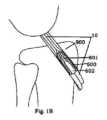
図1Aは、ほとんどの干渉ねじと同様に、より小さい直径を有する2つの連続する縦方向貫通導管(601、602)を備える干渉ねじ(600)を示す。具体的には、2つのうち最小の直径を有する遠位導管(601)は、ねじ留めガイドを導入するように意図される。2つのうち最大の直径を有する近位導管(602)は、ねじ回しを係合するための多角形の内面を有して構成されており、このような導管の他の用途は考えられない。図1Aは、ねじの断面において、両方の導管(601、602)を示す。干渉ねじ(600)は、骨孔の内壁に対して移植片を拘束するように設計された締結装置である。内部導管は、骨孔内にねじを案内してねじ込むための二次的な要素である。Figure 1A shows an interference screw (600) that, like most interference screws, comprises two successive longitudinal through-channels (601, 602) with smaller diameters. In particular, the distal channel (601) with the smallest diameter of the two is intended to introduce a screw-fastening guide. The proximal channel (602) with the largest diameter of the two is configured with a polygonal inner surface for engaging a screwdriver, no other use of such a channel is conceivable. Figure 1A shows both channels (601, 602) in the cross section of the screw. The interference screw (600) is a fastening device designed to restrain the graft against the inner wall of the bone hole. The internal channel is a secondary element for guiding and threading the screw into the bone hole.
干渉ねじの使用に関連するリスクは、骨梁が最大90%の多孔性を有することである。したがって、脛骨の多孔質骨の不一致により、これらの干渉ねじは移動を受け、孔の中に移植片を正確に保持せず、その後修復が失敗する可能性がある。The risk associated with the use of interference screws is that trabecular bone is up to 90% porous. Therefore, due to the mismatch of the porous bone of the tibia, these interference screws may undergo migration and not hold the graft precisely within the pores, resulting in subsequent failure of the repair.
干渉ねじに関連する別の複雑さは、これらが移植片に直接ねじ込まれ、これを損傷するリスクがあること、およびこれらは移植片が締結される張力を正確に制御できるようにしないことである。さらに、装置は、骨孔を広げる可能性があり、これによって移植片の正確な骨結合を減速させて妨害する。Another complication associated with interference screws is that they are screwed directly into the graft, risking damaging it, and they do not allow precise control of the tension to which the graft is fastened. Furthermore, the devices can widen the bone tunnel, thereby slowing down and hindering precise osseointegration of the graft.
この意味において、現在の先端技術では、干渉ねじの場合、極限引張強度、移植片張力損失、骨孔内への装置の移動の可能性、薄筋腱を抽出する必要のない単一の半腱様筋移植片の締結の有効性、および移植片の摺動に対する抵抗に関する現在の締結装置の性能を改善する必要がある。In this sense, the current state of the art requires improving the performance of current fastening devices with regard to ultimate tensile strength, graft tension loss, possibility of device migration into the bone tunnel, efficacy of fastening a single semitendinosus graft without the need for extraction of the gracilis tendon, and resistance to graft sliding in case of interference screws.
干渉ねじおよび皮質ボタンの使用に関連する既述の問題を解決するために、ACL修復のための締結装置を開示する様々な特許が開発されてきた。しかしながら、これらの装置に関連する複雑さは、再建後の関節の機械的特性を調整し続け、干渉ねじおよび皮質ボタンは依然として最も使用される装置である。前記特許のいくつかが、以下に特定される。To solve the previously mentioned problems associated with the use of interference screws and cortical buttons, various patents have been developed disclosing fastening devices for ACL repair. However, the complexities associated with these devices continue to affect the mechanical properties of the joint after reconstruction, and interference screws and cortical buttons remain the most used devices. Some of the aforementioned patents are identified below.
移植片を損傷するリスクを軽減する目的のために、米国特許第6517579号明細書は、ねじがプラグ内に存在する縦中央導管内に導入されたときに、移植片がプラグの外面と骨孔の壁との間に拘束されるように、移植片が配置される外部縦方向チャネルを有するプラグ/スリーブ内に導入されるねじによる移植片の締結からなる技術的解決策を記載している。With the aim of reducing the risk of damaging the graft, US Pat. No. 6,517,579 describes a technical solution consisting of fastening the graft by a screw introduced into a plug/sleeve having an external longitudinal channel in which the graft is placed, so that when the screw is introduced into the longitudinal central channel present in the plug, the graft is restrained between the outer surface of the plug and the wall of the bone hole.
このタイプの技術的解決策は、ねじ留めしている間に移植片がねじと接触するのを防止し、これは実際に、プラグ/スリーブのない干渉ねじで発生する。しかしながら、この技術的解決策は、干渉ねじに関連する主要な問題を抱えており、移植片がプラグの外面と骨孔の壁との間で拘束されるとき、脛骨骨孔の壁の多孔質骨の不一致により、装置は十分な保持力を提供せず、移植片は脛骨骨孔内に摺動する可能性がある。This type of technical solution prevents the graft from coming into contact with the screw during screwing, which indeed occurs with interference screws without a plug/sleeve. However, this technical solution has a major problem associated with interference screws: when the graft is restrained between the outer surface of the plug and the wall of the bone tunnel, due to the mismatch of the porous bone of the wall of the tibial bone tunnel, the device does not provide sufficient retention and the graft may slide into the tibial bone tunnel.
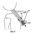
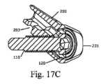
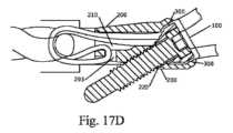
米国特許出願公開第20160100936号明細書は、移植片を収容するフェルールと同軸にねじ込まれるねじを記載している。図1Cおよび図1Dは、前記特許出願の装置を示す。見てわかるように、ねじは移植片に直接ねじ込まれているが、これは干渉ねじの場合のように、移植片を損傷する可能性がある。US20160100936 describes a screw that is threaded coaxially into a ferrule that houses the graft. Figures 1C and 1D show the device of said patent application. As can be seen, the screw is threaded directly into the graft, which can damage the graft, as is the case with interference screws.
国際公開第2006/091278号パンフレットは、骨孔内に導入され、孔の内壁に対して移植片を拘束するねじを記載しており、同時に、ワッシャを有して、皮質骨に対して垂直に侵入し、第1のねじの傾斜面にねじ込まれる第2のねじが、移植片をもう一度拘束する。WO 2006/091278 describes a screw that is introduced into a bone hole and constrains the graft against the inner wall of the hole, while a second screw, with a washer, penetrates perpendicularly into the cortical bone and screws into the beveled surface of the first screw, once again constraining the graft.
この構成において、補強ねじは、締結を実行するために移植片の束の間を分離して必ず通過しなければならず、したがって、
-ねじの実際の傾斜面に形成された領域は、実際の補強ねじによって占有される空間に起因して減少し、したがって締結面が非常に小さく、
-この装置の使用は、ワッシャと限られた開放締め付け領域との間に移植片を嵌合することを伴い、結果的に不完全な締結および/または移植片を損傷する可能性をもたらす。 In this configuration, the reinforcing screw must necessarily pass through separation between the graft bundles to effect fastening, and therefore
- the area formed on the actual bevel of the screw is reduced due to the space occupied by the actual reinforcing screw, and therefore the fastening surface is very small;
- Use of this device involves fitting the graft between a washer and a limited open clamping area, resulting in incomplete fastening and/or potential damage to the graft.
米国特許第2006052787号明細書は、国際公開第2006/091278号パンフレットで提案されたものと同様の解決策を提案するが、ねじは非ねじ拘束要素に置き換えられている。図1Eおよび図1Fは、前記特許出願の装置を示す。見てわかるように、移植片(10)は必然的に、拘束要素(801)の外面と骨の骨孔の壁との間を通過し、次いで拘束要素の傾斜面に向かって屈曲し、ワッシャを有するねじ(802)が前記要素に対して移植片(10)を押しつける。US2006052787 proposes a solution similar to that proposed in WO2006/091278, but where the screw is replaced by a non-threaded constraining element. Figures 1E and 1F show the device of said patent application. As can be seen, the graft (10) necessarily passes between the outer surface of the constraining element (801) and the wall of the bone hole, then bends towards the inclined surface of the constraining element, where the screw (802) with the washer presses the graft (10) against said element.
国際公開第2015/169978号パンフレットは、縦導管およびねじ留め要素を用いる移植片の締結、ならびにフェルールの近位上部リム内のみにある締結通路を記載している。図2Aから図2Eは、前記特許出願の装置を示す。実際には、この装置は以下の制限を示している。
-近位上部リムは顕著な保持屈曲部を提供するものの、これは移植片の一部を拘束されないままにする制限された保持通路を提供し、拘束された移植片の摺動に対する抵抗を低減し、このため装置は、移植片全体を拘束するようにサイズ変更されなければならない。
-十分な厚さを達成するために、3本鎖または4本鎖構成で折り畳まれ、これは皮質締結には短すぎるので、国際公開第2015/169978号パンフレットに記載されるタイプの、皮質骨上に配置された直接機械的拘束装置の使用は、単一の半腱様筋移植片によるACL修復を可能にしない。 WO 2015/169978 describes the fastening of the graft using longitudinal channels and screw-fastening elements, and the fastening passages being only in the proximal upper rim of the ferrule. Figures 2A to 2E show the device of said patent application. In practice, this device presents the following limitations:
- Although the proximal upper rim provides a significant retention flexure, it provides a limited retention passageway that leaves part of the graft unconstrained, reducing resistance to sliding of the constrained graft, so the device must be sized to restrain the entire graft.
The use of direct mechanical restraint devices placed on cortical bone, of the type described in WO 2015/169978, does not allow for ACL repair with a single semitendinosus graft, as it is folded in a three- or four-strand configuration to achieve sufficient thickness, which is too short for cortical fastening.
米国特許出願公開第2013/304099号明細書は、骨孔内に移植組織を固定するための固定装置を記載している。U.S. Patent Application Publication No. 2013/304099 describes a fixation device for fixing a graft in a bone tunnel.
米国特許出願公開第2008/051795号明細書は、準備された骨孔内に靱帯または移植片を固定するために好ましく使用される組織固定装置を記載している。U.S. Patent Application Publication No. 2008/051795 describes a tissue fixation device that is preferably used to fix a ligament or graft in a prepared bone tunnel.
したがって、骨孔内に少なくとも1つの移植片を締結し、現在の装置の性能を改善し、必要な剛性および力を提供し、既述の問題を解決することを可能にする解決策を提供する必要がある。There is therefore a need to provide a solution that allows fastening at least one graft within a bone tunnel, improves the performance of current devices, provides the necessary stiffness and force, and overcomes the problems discussed above.
本発明は、請求項1に記載の移植片を締結するための医療締結装置、および請求項14に記載の医療締結装置を挿入するためのシステムによる、前述の問題に対する解決策を提案する。本発明の好適な実施形態は、従属請求項において定義されている。The present invention proposes a solution to the aforementioned problems by a medical fastening device for fastening grafts according to
第1の発明の態様では、移植片の締結のための医療締結装置であって、医療締結装置は、骨の骨孔に挿入されるのに適しており、前記医療締結装置は、
-第1の締結要素と、
-第2の締結要素であって、
・第1の端部および第2の端部を有する第1の貫通導管であって、前記第1の貫通導管は第1の縦軸に沿って延在し、前記第1の貫通導管は、その第1の端部に移植片を受容し、その第2の端部でその中に移植片を収容するように構成されている、第1の貫通導管と、
・第1の端部および第2の端部を有する第2の締結導管であって、前記第2の締結導管は第2の縦軸に沿って延在する、第2の締結導管と、
を備える第2の締結要素と、
を備え、
第1の貫通導管および第2の締結導管は、第1の縦軸および第2の縦軸が、互いに0以外である角度αを画定するように、第2の締結要素内に配置され、
第1の貫通導管の第2の端部および第2の締結導管の第2の端部は、接合されて環状近位表面を画定し、
第1の締結要素が締結導管内に収容および締結されると、第1の締結要素と環状近位表面との間に環状締結通路が画定されるようになっている、
医療締結装置が提供される。 In a first aspect of the invention there is provided a medical fastening device for fastening an implant, the medical fastening device being adapted to be inserted into a bone tunnel in a bone, said medical fastening device comprising:
a first fastening element,
a second fastening element,
a first through conduit having a first end and a second end, the first through conduit extending along a first longitudinal axis, the first through conduit configured to receive an implant at its first end and to accommodate an implant therein at its second end;
a second fastening conduit having a first end and a second end, the second fastening conduit extending along a second longitudinal axis; and
A second fastening element comprising:
Equipped with
the first through conduit and the second fastening conduit are disposed within the second fastening element such that the first longitudinal axis and the second longitudinal axis define a non-zero angle α with respect to each other;
a second end of the first through conduit and a second end of the second fastening conduit joined to define an annular proximal surface;
When the first fastening element is received within the fastening conduit and fastened, an annular fastening passage is defined between the first fastening element and the annular proximal surface.
A medical fastening device is provided.
一実施形態では、第1の縦軸は、第1の貫通導管の軸方向の対称軸と一致する。前述の実施形態のいずれかと両立する別の実施形態では、第2の締結導管は、第1の締結要素を収容および締結するように構成されている。前述の実施形態のいずれかと両立する別の実施形態では、第2の締結導管は、第2の縦軸に沿って延在する。In one embodiment, the first longitudinal axis coincides with an axial axis of symmetry of the first through conduit. In another embodiment compatible with any of the aforementioned embodiments, the second fastening conduit is configured to receive and fasten the first fastening element. In another embodiment compatible with any of the aforementioned embodiments, the second fastening conduit extends along the second longitudinal axis.
本明細書を通して、移植片は、以下のように理解される。
-実際の患者からの任意のタイプの自家移植片、
-ドナーからの任意のタイプの同種移植片または異種移植片、もしくは
-任意のタイプの人工移植片、可撓性材料、または合成インプラント。 Throughout this specification, a graft is understood as follows.
- any type of autograft from a real patient,
- any type of allograft or xenograft from a donor, or - any type of artificial graft, flexible material, or synthetic implant.
本明細書を通して、医療締結装置の各要素の第1の端部は、前記要素の遠位端、すなわち、骨孔に挿入されたときに外科医から最も遠い要素の端部を意味すると理解されるだろう。一方、医療締結装置の各要素の第2の端部は、前記要素の近位端、すなわち、骨孔に挿入されたときに外科医から最も近い要素の端部を意味すると理解されるだろう。一方、第1の貫通導管および第2の締結導管の両方が中空であることもまた理解されるだろう。Throughout this specification, the first end of each element of the medical fastening device will be understood to mean the distal end of said element, i.e. the end of the element that is furthest from the surgeon when inserted into a bone hole, while the second end of each element of the medical fastening device will be understood to mean the proximal end of said element, i.e. the end of the element that is closest to the surgeon when inserted into a bone hole, while it will also be understood that both the first through conduit and the second fastening conduit are hollow.
この意味において、近位要素または近位端は、それぞれ、外科医による使用のための第2の締結要素の最も近い把持位置に位置する要素または領域である。したがって、第2の締結要素が骨孔に導入されたとき、近位端は、外科医に最も近く、骨孔から最も離れた領域である。遠位要素または遠位領域は、それぞれ、外科医によるその使用のために最も遠い、したがって骨孔に最も近い位置にある、要素または領域である。したがって、第2の締結要素が骨孔に導入されたとき、遠位領域は、外科医から最も遠く、骨孔に最も近い領域である。In this sense, the proximal element or proximal end is the element or region, respectively, that is located at the closest gripping position of the second fastening element for use by the surgeon. Thus, when the second fastening element is introduced into the bone hole, the proximal end is the region that is closest to the surgeon and furthest from the bone hole. The distal element or distal region is the element or region, respectively, that is furthest for its use by the surgeon and thus located closest to the bone hole. Thus, when the second fastening element is introduced into the bone hole, the distal region is the region that is furthest from the surgeon and closest to the bone hole.
第2の締結要素の第1の貫通導管は、貫通導管の端部の一方を通じて移植片を受容し、これを通じて移植片の端部の少なくとも一方が環状近位表面の内部または内面に位置するまで前記移植片を導くように構成されている。The first through-conduit of the second fastening element is configured to receive the graft through one of its ends and to guide the graft therethrough until at least one of the ends of the graft is positioned within or on the inner surface of the annular proximal surface.
環状近位表面は、医療締結装置の第2の端部に位置している。具体的には、環状近位表面は、第1の貫通導管の第2の端部および第2の締結導管の第2の端部を接合するリムである。有利には、環状近位表面は、移植片が保持屈曲部を有する第1の縦軸から分離するように、移植片を案内する。前記リムの結果として、保持屈曲部は、リムの周縁の任意の部分に形成されることが可能であり、締結を補強する。The annular proximal surface is located at the second end of the medical fastening device. In particular, the annular proximal surface is a rim joining the second end of the first through conduit and the second end of the second fastening conduit. Advantageously, the annular proximal surface guides the graft so that it separates from the first longitudinal axis with a retaining bend. As a result of said rim, the retaining bend can be formed at any part of the rim's periphery, reinforcing the fastening.
環状近位表面の内面は、環状締結通路の一部であり、有利には、先端技術の前述の要素のものよりも大きい締結通路を用いていくつかの移植片の締結を可能にする。したがって、本発明の装置は、1つ以上の移植片を締結するように構成されている。The inner surface of the annular proximal surface is part of an annular fastening passage, advantageously allowing fastening of several grafts using a fastening passage larger than those of the aforementioned elements of the state of the art. Thus, the device of the present invention is configured to fasten one or more grafts.
環状近位表面の配置は、第1の貫通導管の第2の端部および第2の締結導管の第2の端部の接合部を画定する周縁を連続的に延長するので、環状締結通路が環状であることは、理解されなければならない。It should be appreciated that the annular fastening passage is annular because the annular proximal surface arrangement extends continuously around the periphery defining the junction of the second end of the first through conduit and the second end of the second fastening conduit.
環状締結通路の表面の内面は締結面である。締結面は、移植片が環状締結通路内に収容され、締結面を構成する表面上に固定されるように、移植片を締結する表面である。The inner surface of the surface of the annular fastening passage is the fastening surface. The fastening surface is a surface to which the graft is fastened such that the graft is received within the annular fastening passage and secured onto the surface that constitutes the fastening surface.
したがって、移植片が環状締結通路内に収容され、次いで締結通路を構成する表面の間に固定されたときに、移植片を締結および固定できるように、環状締結通路は、第1の締結要素が第2の締結導管内に収容されたときに、第1の締結要素と第2の締結要素の第2の端部の環状近位表面の内面との間に画定された空間または容積である。移植片の経路は、直線、湾曲、ジグザグ、屈曲、または医学文献に示されるその他任意の形状であり得る。有利には、前記環状締結通路は、締結が完全であり、先端技術の装置と比較してより簡単で信頼性の高い方法で実行されることを保証する。Thus, the annular fastening passage is the space or volume defined between the first fastening element and the inner surface of the annular proximal surface of the second end of the second fastening element when the first fastening element is received within the second fastening conduit such that the graft can be fastened and secured when received within the annular fastening passage and then secured between the surfaces constituting the fastening passage. The path of the graft can be straight, curved, zigzag, bent, or any other shape shown in the medical literature. Advantageously, said annular fastening passage ensures that fastening is complete and is performed in an easier and more reliable manner compared to state of the art devices.
一実施形態では、環状近位表面は、環状周縁全体に沿って延長し、近位空洞を画定する。In one embodiment, the annular proximal surface extends along the entire annular circumference and defines a proximal cavity.
近位空洞は、医療締結装置の第2の端部または近位端に位置し、あらゆる空洞と同様に、前記容積を画定する底部および外側開口部を備える。したがって、空洞の底部および開口部は、所与の距離だけ互いに分離されている。The proximal cavity is located at the second or proximal end of the medical fastening device and, like any cavity, has a bottom and an outer opening that define said volume. Thus, the bottom and opening of the cavity are separated from each other by a given distance.
近位空洞の底部は、第1の貫通導管の第2の端部と第2の締結導管の第2の端部との間の接合部を画定する。特定の実施形態では、環状近位表面および近位空洞は、第1の締結要素を収容するように意図された第2の締結導管の第2の縦軸の周りに位置している。The bottom of the proximal cavity defines a junction between the second end of the first through conduit and the second end of the second fastening conduit. In certain embodiments, the annular proximal surface and the proximal cavity are located about a second longitudinal axis of the second fastening conduit intended to accommodate the first fastening element.
環状近位表面は、骨材と接触するように意図される外面、および移植片と接触するように意図される内面の、2つの表面を備える。近位空洞は、第1および第2の縦軸から分離する突出部のように第2の締結要素から現れるように、第1の貫通導管および第2の締結導管の延長部と見なされることが可能である。The annular proximal surface comprises two surfaces: an outer surface intended to contact the bone material, and an inner surface intended to contact the graft. The proximal cavity can be considered as an extension of the first through conduit and the second fastening conduit, emerging from the second fastening element as a protrusion separating the first and second longitudinal axes.
したがって、この実施形態では、環状締結通路は、少なくとも1つの移植片の締結を可能にするように、第1の締結要素が第2の締結導管に収容されたときに、第1の締結要素と環状近位表面との間に画定された空間または容積である。Thus, in this embodiment, the annular fastening passage is a space or volume defined between the first fastening element and the annular proximal surface when the first fastening element is received in the second fastening conduit to allow fastening of at least one graft.
有利には、この実施形態は、近位空洞を環状締結通路の一部とすることができ、実質的かつ有利に締結面を増加させる。したがって、本発明の締結装置の締結面および環状締結通路は、移植片の締結および可能性を補強し、結果的に修復を成功させる。この新しい構成は、移植片が拘束されたときにその膨張に適応するのに十分な環状の締結面を、移植片に提供する。Advantageously, this embodiment allows the proximal cavity to be part of the annular fastening passage, substantially and advantageously increasing the fastening surface. Thus, the fastening surface and annular fastening passage of the fastening device of the present invention enhance the fastening and potential of the graft, resulting in a successful repair. This new configuration provides the graft with sufficient annular fastening surface to accommodate the expansion of the graft when it is restrained.
これにより、少なくとも1つの移植片における締結力を増加させ、最適な締結を得ることを可能にし、こうして先端技術で観察された問題を解決する。これは、ねじ自体によって占有される面積に起因して非常に小さいまたは減少した締結面が利用可能なため、達成される締結が不完全になり得る、干渉ねじの傾斜した近位端にある締結装置に起こることとは異なる。This allows increasing the fastening force in at least one implant and obtaining optimal fastening, thus solving a problem observed in the state of the art. This is different from what happens with fastening devices at the beveled proximal end of an interference screw, where a very small or reduced fastening surface is available due to the area occupied by the screw itself, which may result in incomplete fastening being achieved.
有利には、本発明の環状締結通路は、移植片の完全な締結を提供し、これにより、移植片が拘束される際に移植片の材料の一部が環状締結通路から出てくるのを防止し、これによって先端技術で観察された問題を解決する。これは、締結面が非常に小さいまたは減少したときに締結が不完全なことがある、別の締結装置に起こることとは異なる。Advantageously, the annular fastening passage of the present invention provides complete fastening of the graft, thereby preventing some of the graft material from exiting the annular fastening passage as the graft is restrained, thereby solving a problem observed in the state of the art. This is different from what happens with other fastening devices, where fastening can be incomplete when the fastening surface is very small or reduced.
特定の実施形態では、第2の締結要素は、締結フェルールである。In certain embodiments, the second fastening element is a fastening ferrule.
特定の実施形態では、第2の締結要素は、第1の端部および第2の端部を有する遠位付属物を備える。In certain embodiments, the second fastening element includes a distal appendage having a first end and a second end.
別の特定の実施形態では、遠位付属物の第2の端部は、第1の貫通導管の第1の端部に接続されており、遠位付属物は、第1の貫通導管の第1の端部から突出している。好ましくは、遠位付属物は、第1の貫通導管の第1の端部に接続されている。In another particular embodiment, the second end of the distal appendage is connected to the first end of the first through conduit, and the distal appendage protrudes from the first end of the first through conduit. Preferably, the distal appendage is connected to the first end of the first through conduit.
特定の実施形態では、遠位付属物の第2の端部は、第1の貫通導管内に追加で収容されて前記第1の貫通導管を2つのセクションに分割し、第1の端部は、第1の貫通導管の第1の端部から突出している。In certain embodiments, the second end of the distal appendage is additionally received within the first through conduit to divide said first through conduit into two sections, with the first end protruding from the first end of the first through conduit.
別の追加の実施形態では、第1の貫通導管は、軸対称性を有する。一方、遠位付属物は、第1の貫通導管の第1の端部の進入セクションに対して垂直な第1の平面上に位置している。この位置は、本明細書を通して、垂直位置にある遠位付属物と見なされる。In another additional embodiment, the first through conduit has axial symmetry, while the distal appendage is located on a first plane perpendicular to the entry section of the first end of the first through conduit. This position is considered throughout this specification as the distal appendage being in a vertical position.
別の実施形態では、遠位付属物は、第1の貫通導管の第1の端部の進入セクションに対して垂直な第2の平面上に位置しており、これはまた、前述の実施形態において定義された第1の貫通導管の第1の端部の進入セクションに対して垂直な第1の平面に対しても垂直である。この位置は、本明細書を通して、水平位置にある遠位付属物と見なされる。In another embodiment, the distal appendage is located on a second plane perpendicular to the entry section of the first end of the first through conduit, which is also perpendicular to the first plane perpendicular to the entry section of the first end of the first through conduit defined in the previous embodiment. This position is considered throughout this specification as the distal appendage being in a horizontal position.
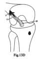
遠位付属物は、少なくとも1つの移植片の枝を離れたまま維持することを可能にする。有利には、これらの実施形態は、単一の脛骨骨孔による十字靱帯の解剖学的修復において、移植片の枝の関節内セグメントに、修復される膝の特定の屈伸位置で元のACLが有する正確な度合いのねじれを提供することを可能にすることができる。関節内セグメントは、脛骨および大腿骨の両方の関節内空洞への挿入間の移植片のセグメントを指すことが理解されなければならない。したがって、これは、脛骨および大腿骨の両方の骨を接合し、骨孔の外側、すなわちACLが元々位置していた場所に位置する、移植片の部分全体に対応する。The distal attachment allows at least one branch of the graft to be kept apart. Advantageously, these embodiments can allow for an anatomical repair of the cruciate ligament with a single tibial tunnel to provide the intra-articular segment of the branch of the graft with the exact degree of twist that the original ACL has in the particular flexion and extension position of the repaired knee. It should be understood that the intra-articular segment refers to the segment of the graft between the insertions into the intra-articular cavities of both the tibia and the femur. This therefore corresponds to the entire portion of the graft that joins both the tibia and the femur bones and is located outside the tunnel, i.e., where the ACL was originally located.
単一の脛骨骨孔によるACL修復では、遠位付属物は、有利には、脛骨骨孔内に、ACLの2つの主要な枝、前内側(AM)枝および後外側(PL)枝を、元の挿入の両方の枝に対応する位置まで導くことを可能にする。したがって、ACLの元の解剖学的構造が、有利に修復される。In a single tibial tunnel ACL repair, the distal attachment advantageously allows the two major branches of the ACL, the anterior medial (AM) branch and the posterolateral (PL) branch, to be guided into the tibial tunnel to positions corresponding to both branches of their original insertion. Thus, the original anatomy of the ACL is advantageously restored.
有利には、遠位付属物が移植片の枝を特定の距離だけ離れたまま維持する1つ以上の実施形態において、脛骨および/または大腿骨で二重骨孔技術を使用する必要性を伴わずに、脛骨および大腿骨の両方で、この分離が元のACLの広い挿入領域を修復できるようにする、より解剖学的なACL修復を可能にする。Advantageously, in one or more embodiments where the distal attachment maintains the branches of the graft apart at a specific distance, this separation allows for a more anatomical ACL repair in both the tibia and femur, allowing for the restoration of a wide insertion area of the native ACL, without the need to use a dual-hole technique in the tibia and/or femur.
一実施形態では、遠位付属物の第1の端部は、穴を追加的に備え、前記穴は、第1の締結要素が第2の締結要素の第2の締結導管内に収容および締結されたときに、医療締結装置が移植片の少なくとも1つの自由端を締結することを可能にし、同時に、穴が移植片の少なくとも1つの屈曲端の吊りを維持することを可能にするように、移植片の屈曲端の吊りを意図している。In one embodiment, the first end of the distal appendage additionally comprises a hole intended for suspending the bent end of the graft such that when the first fastening element is received and fastened within the second fastening conduit of the second fastening element, the hole allows the medical fastening device to fasten at least one free end of the graft while at the same time allowing the hole to maintain the suspension of at least one bent end of the graft.
穴を有する遠位付属物は、穴を通じて導入されたときに移植片の吊りを可能にするので、移植片の屈曲端を受容するように構成された吊り要素である。この構成は、移植片の自由端が元に戻ることを可能にするので、これらは締結されることが可能である。十分な長さの単一の移植片による十字靱帯修復では、これにより、縫合または結び目を使用しない3本鎖または4本鎖移植片構成の使用を有利に可能になる。縫合または結び目の使用を防止することで、移植片の両方の自由端を装置によって直接機械的に締結することができる。The distal appendage with holes is a hanging element configured to receive the bent ends of the graft, allowing for the graft to be suspended when introduced through the holes. This configuration allows the free ends of the graft to return so they can be fastened. In cruciate ligament repairs with a single graft of sufficient length, this advantageously allows for the use of a three-strand or four-strand graft configuration without the use of sutures or knots. By preventing the use of sutures or knots, both free ends of the graft can be mechanically fastened directly by the device.
有利には、移植片の関節内セグメントが3本鎖または4本鎖構成であっても、2つの自由端が関節内領域を通る経路から回り込んで、脛骨から大腿骨へ、そして大腿骨から脛骨へ回り込んで戻ってくると、装置はその2つの自由端を締結するだけでよいので、この構成は装置のサイズを縮小する。Advantageously, even if the intra-articular segment of the implant is a three-strand or four-strand configuration, this configuration reduces the size of the device since the device only needs to fasten the two free ends as they are routed from a path through the intra-articular region and looped around from the tibia to the femur and back around from the femur to the tibia.
したがって、単一の脛骨骨孔を用いる3本鎖構成では、移植片は2つのループ、脛骨ループおよび大腿骨ループで構成され、これらは、大腿骨締結装置によって締結された脛骨穴から来る移植片の自由端と、脛骨締結装置によって締結された大腿骨穴から来る移植片の自由端とを用いて、それぞれの脛骨および大腿骨締結装置のそれぞれの穴から吊られている。Thus, in a three-strand configuration using a single tibial hole, the graft is composed of two loops, a tibial loop and a femoral loop, which are suspended from respective holes in the respective tibial and femoral fasteners, with the free end of the graft coming from the tibial hole fastened by the femoral fastener and the free end of the graft coming from the femoral hole fastened by the tibial fastener.
一実施形態では、遠位付属物は好ましくはストリップ、コード、またはバンドであり、遠位付属物の第1の端部は第2の締結要素に接続され、遠位付属物の第2の端部は自由端であり、第1の締結要素が締結導管内に収容および締結されると、追加的に遠位付属物の第2の端部が締結通路内に収容されるように、調整可能ループを構成し、調整可能ループは、移植片の屈曲端の吊りを意図している。In one embodiment, the distal attachment is preferably a strip, cord, or band, the first end of the distal attachment is connected to the second fastening element, the second end of the distal attachment is a free end, and comprises an adjustable loop such that when the first fastening element is received and fastened within the fastening conduit, the second end of the distal attachment is additionally received within the fastening passage, the adjustable loop being intended for hanging the bent end of the graft.
有利には、皮質ボタンとは異なり、この調整可能ループは結び目を必要とせず、必要に応じて、その屈曲端が調整可能ループから吊られる移植片の張力を変化させるために第1の締結要素が緩められ得るように、修正されることが可能である。Advantageously, unlike cortical buttons, this adjustable loop does not require knotting and can be modified, if necessary, such that the first fastening element can be loosened to change the tension of the graft whose bent end is suspended from the adjustable loop.
特定の方法で、前述の実施形態のストリップ、コード、またはバンドの形態の遠位付属物が編み込まれるかまたは織り込まれる。In a particular manner, the distal appendages in the form of strips, cords, or bands of the aforementioned embodiments are braided or woven.
特定の実施形態では、遠位付属物は好ましくはストリップ、コード、またはバンドであり、遠位付属物の第1の端部および第2の端部は第2の締結要素に接続され、穴を構成し、穴は、第1の締結要素が第2の締結要素の第2の締結導管内に収容および締結されたときに、医療締結装置は移植片の少なくとも1つの自由端を締結することを可能にし、同時に、穴は移植片の少なくとも1つの屈曲端の吊りを維持するように、移植片の屈曲端の吊りを意図している。遠位付属物の両端が接続されているので、遠位付属物は締結されており、調整不可能である。In a particular embodiment, the distal appendage is preferably a strip, cord, or band, the first and second ends of the distal appendage being connected to the second fastening element and constituting a hole, the hole being intended for the suspension of the bent end of the graft, such that when the first fastening element is received and fastened within the second fastening conduit of the second fastening element, the medical fastening device fastens at least one free end of the graft, while at the same time the hole maintains the suspension of at least one bent end of the graft. Since both ends of the distal appendage are connected, the distal appendage is fastened and non-adjustable.
特定の方法で、前述の実施形態のストリップ、コード、またはバンドの形態の遠位付属物が編み込まれるかまたは織り込まれる。In a particular manner, the distal appendages in the form of strips, cords, or bands of the aforementioned embodiments are braided or woven.
特定の実施形態では、第1の締結要素は、ねじ軸およびヘッドを有するねじ、ならびにワッシャであり、
-ねじのヘッドは、ねじの軸と同心の円形段差を備え、
-ワッシャは、ねじの軸と同心の円形段差に対して相補的な形状を有する内側円形段差を備え、前記内側円形段差は、ねじのヘッドを受容するためのワッシャの領域内に位置している。 In a particular embodiment, the first fastening element is a screw having a threaded shaft and a head, and a washer;
- the head of the screw is provided with a circular step concentric with the axis of the screw,
the washer comprises an inner circular step having a shape complementary to a circular step concentric with the axis of the screw, said inner circular step being located in the area of the washer intended to receive the head of the screw;
ワッシャの内表面は、ねじを収容するように意図された内面またはセクションであり、これは前記円形段差が位置する場所である。一方、ワッシャの外表面は、移植片および/または環状近位表面と接触するように意図されるワッシャの外面である。The inner surface of the washer is the inner surface or section intended to accommodate the screw, which is where the circular step is located, while the outer surface of the washer is the outer surface of the washer intended to contact the graft and/or the annular proximal surface.
有利には、この実施形態は、ねじの軸と同軸ではない位置までワッシャが引きずられるのを防止し、これにより、ねじの回転運動がワッシャに伝わるのを防止して、本発明の医療締結装置の挿入および締結を容易にする。Advantageously, this embodiment prevents the washer from being dragged to a position that is not coaxial with the axis of the screw, thereby preventing the rotational motion of the screw from being transmitted to the washer, facilitating insertion and fastening of the medical fastening device of the present invention.
特定の実施形態では、第1の締結要素は、
-円形のヘッドおよびそのシャンク上のねじ山を有するねじと、
-ねじのヘッド内に収容されるように構成された円形のワッシャと、
を備え、
第2の締結導管は、ねじを第2の導管に締結するように構成されたねじのねじ山と相補的なねじ山を備える。 In a particular embodiment, the first fastening element comprises:
- a screw with a circular head and a thread on its shank;
- a circular washer adapted to be received in the head of the screw;
Equipped with
The second fastening conduit includes threads complementary to the threads of the screw configured to fasten the screw to the second conduit.
ワッシャは、オリフィスと、オリフィスから内表面が終端する外縁部まで延在する内表面とを備える。オリフィスは、ねじのシャンクを受容するように構成されており、ワッシャの内表面は、ねじのヘッドを収容するように構成されている。ワッシャを備える実施形態では、ワッシャの外表面と環状近位表面の内面との間に締結面が構成されている。The washer includes an orifice and an inner surface extending from the orifice to an outer edge where the inner surface terminates. The orifice is configured to receive the shank of the screw and the inner surface of the washer is configured to accommodate the head of the screw. In embodiments including a washer, a fastening surface is defined between the outer surface of the washer and the inner surface of the annular proximal surface.
これらの実施形態では、環状近位表面がねじのねじ切り軸の周りに構成された結果として、近位空洞の開口部全体を完全に包囲するので、本発明の締結装置は、移植片を引きずることなく、ならびに締結中に締結ねじが移植片を貫通することなく、より大きい圧縮力を印加することを可能にする。したがって、本発明は、ワッシャを有するねじによって現在の装置で発生するように、ねじが必然的に移植片を貫通して劣化させることを防止する。In these embodiments, because the annular proximal surface is configured around the threaded axis of the screw, and as a result completely surrounds the entire opening of the proximal cavity, the fastening device of the present invention allows for greater compressive forces to be applied without dragging the graft and without the fastening screw penetrating the graft during fastening. Thus, the present invention prevents the screw from necessarily penetrating and degrading the graft, as occurs with current devices with screws having washers.
有利には、移植片は、ワッシャの外面の広いセクタと、環状近位表面の内面との間に配置される。本発明の装置は、先端技術のねじおよびワッシャ装置によって提供されるよりも高い締結剛性を提供する。Advantageously, the graft is disposed between a wide sector of the outer surface of the washer and the inner surface of the annular proximal surface. The device of the present invention provides greater fastening stiffness than is provided by state of the art screw and washer devices.
特定の実施形態では、第2の締結要素は、第1の貫通導管と第2の締結導管との間で移動可能な可動接合領域を備え、前記可動接合領域は、
-第2の締結導管の内部の第1の位置まで移動し、
-第1の貫通導管の内部の第2の位置まで移動する、
ように構成されている。 In a particular embodiment, the second fastening element comprises a movable joint area movable between the first through conduit and the second fastening conduit, said movable joint area comprising:
- moving to a first position inside a second fastening conduit;
- moving to a second position within the first through conduit;
It is structured as follows.
接合領域は、第1の貫通導管の第2の端部と第2の締結導管の第2の端部との縁部が接合する領域として理解されなければならない。The joining area should be understood as the area where the edges of the second end of the first through conduit and the second end of the second fastening conduit join.
一方では、第1の位置は、移植片を収容するための余裕を残す。他方では、第2の位置は、移植片が第2の締結導管内に挿入されている間に第1の締結要素によって挟持および/または穿孔されることを防止することによって、移植片を保護する。On the one hand, the first position leaves room to accommodate the graft. On the other hand, the second position protects the graft by preventing it from being pinched and/or punctured by the first fastening element while it is being inserted into the second fastening conduit.
特定の実施形態では、第2の締結要素の第2の端部は、第2の縦軸に対して垂直な軸上に位置する少なくとも1つのフランジを追加で備える。好ましくは、少なくとも1つのフランジは、環状保持ローブの形態である。In certain embodiments, the second end of the second fastening element additionally comprises at least one flange located on an axis perpendicular to the second longitudinal axis. Preferably, the at least one flange is in the form of an annular retaining lobe.
少なくとも1つのフランジは、骨孔内への入口開口部の外側上部分を区切る皮質骨に当接するように構成されている。有利には、この実施形態は、骨孔内の本発明の医療締結装置の移動を防止する。At least one flange is configured to abut against the cortical bone that bounds the outer upper portion of the entrance opening into the bone hole. Advantageously, this embodiment prevents migration of the medical fastening device of the present invention within the bone hole.
特定の実施形態では、角度(α)は30°から60°の間である。In a particular embodiment, the angle (α) is between 30° and 60°.
好適な実施形態では、第2の締結要素の第2の端部は、第2の縦軸に対して垂直な軸上に位置する2つのフランジを備える。In a preferred embodiment, the second end of the second fastening element has two flanges located on an axis perpendicular to the second longitudinal axis.
調整可能ループを有する特定の実施形態では、第2の締結要素は、第1の締結要素内に存在する溝と相補的な溝、好ましくはワッシャのないねじを追加的に備える、ストリップまたはバンドを備える。有利には、この実施形態は、装置を構成する調整可能ループの締結を補強する。In a particular embodiment with an adjustable loop, the second fastening element comprises a strip or band additionally comprising a groove complementary to the groove present in the first fastening element, preferably a washer-free screw. Advantageously, this embodiment reinforces the fastening of the adjustable loop constituting the device.
一実施形態では、第2の締結要素は一体型である。In one embodiment, the second fastening element is integral.
一実施形態では、医療締結装置の要素は、半結晶性で生体適合性の熱可塑性ポリマー材料から製造される。In one embodiment, the elements of the medical fastening device are fabricated from a semi-crystalline, biocompatible thermoplastic polymer material.
特定の実施形態では、第1の締結要素はチタンから製造され、第2の締結要素はポリエーテルエーテルケトンから製造される。In a particular embodiment, the first fastening element is made from titanium and the second fastening element is made from polyetheretherketone.
特定の実施形態では、第2の締結要素はツーピースであり、第1の部分はポリエーテルエーテルケトンから製造され、クリップ留めおよび/または超音波によって結合されており、第2の部分は織り込みまたは編み込みされたコードまたはバンドを備える。In certain embodiments, the second fastening element is two-piece, with a first part made from polyetheretherketone and clipped and/or ultrasonically bonded, and a second part comprising a woven or braided cord or band.
別の特定の実施形態では、第2の締結要素はツーピースであり、ポリエーテルエーテルケトンから製造され、チタンリングまたは半リングを有する。In another particular embodiment, the second fastening element is two-piece and manufactured from polyetheretherketone and has a titanium ring or half ring.
特定の実施形態では、第2の締結要素は、その外表面に少なくとも1つの縦または螺旋リブを備える。In certain embodiments, the second fastening element has at least one longitudinal or helical rib on its outer surface.
有利には、第2の締結要素がその外表面に少なくとも1つの縦リブを備える実施形態では、締結ねじがねじ込まれる際の骨孔の中の第2の締結要素の回転が防止される。Advantageously, in embodiments in which the second fastening element has at least one longitudinal rib on its outer surface, rotation of the second fastening element in the bone hole is prevented when the fastening screw is screwed in.
特定の実施形態では、環状近位表面は、その内面に少なくとも1つのスロットまたは溝を備える。別の実施形態では、環状近位表面は、その内面に少なくとも1つのリブまたは突起を備える。別の実施形態では、環状近位表面は、その内面に少なくとも1つの溝および少なくとも1つのリブを備える。In certain embodiments, the annular proximal surface comprises at least one slot or groove on its inner surface. In other embodiments, the annular proximal surface comprises at least one rib or protrusion on its inner surface. In other embodiments, the annular proximal surface comprises at least one groove and at least one rib on its inner surface.
有利には、締結面の内面が少なくとも1つの溝および/またはリブを備える実施形態では、移植片上の締結が補強される。Advantageously, in embodiments where the inner surface of the fastening surface comprises at least one groove and/or rib, fastening on the graft is reinforced.
第2の発明の態様では、本発明は、医療締結装置を挿入するためのシステムであって、
-第1の発明の態様の実施形態のいずれかによる医療締結装置と、
-インサータであって、
・第2の締結要素の形状に対して相補的な形状を有し、第2の締結要素の第2の端部と係合するように構成された、第1の端部と、
・インサータの第2の端部に位置するハンドルと、
を備えるインサータと、
-連結ねじと、
を備えるシステムを提供する。 In a second aspect, the present invention provides a system for inserting a medical fastening device, comprising:
a medical fastening device according to any of the embodiments of the first aspect of the invention,
- an inserter,
a first end having a shape complementary to the shape of a second fastening element and configured to engage a second end of the second fastening element;
a handle located at a second end of the inserter;
an inserter comprising:
- a connecting screw,
The present invention provides a system comprising:
具体的には、本発明のインサータシステムは、患者に医療締結装置を埋め込むための迅速で効率的なシステムを提供することを可能にする。Specifically, the inserter system of the present invention makes it possible to provide a fast and efficient system for implanting a medical fastening device in a patient.
さらなる例では、移植片の締結のための医療締結装置であって、医療締結装置は、骨の骨孔に挿入されるのに適しており、前記医療締結装置は、
-第1の締結要素と、
-第2の締結要素であって、
・骨に対して、もしくは装置自体に対して締結するための締結通路を構成する第1の締結要素を収容するように意図された締結導管と、
・移植片の少なくとも1つの屈曲端の吊りを意図した吊り要素、好ましくは穴またはループを構成する、遠位付属物と、
を備える第2の締結要素と、
を備える医療締結装置が提供される。 In a further example, there is provided a medical fastening device for fastening an implant, the medical fastening device being adapted to be inserted into a bone hole in a bone, said medical fastening device comprising:
a first fastening element,
a second fastening element,
a fastening conduit intended to accommodate a first fastening element constituting a fastening passage for fastening to the bone or to the device itself;
a distal appendage constituting a suspension element, preferably a hole or a loop, intended for suspension of at least one bent end of the graft;
A second fastening element comprising:
A medical fastening device is provided comprising:
第1の発明の態様で示された移植片の定義は、第3の発明の態様の全ての実施形態でも必要な修正を加えて適用されることが、理解されなければならない。It should be understood that the definition of implant given in the first aspect of the invention applies mutatis mutandis to all embodiments of the third aspect of the invention.
穴またはループは、移植片の屈曲端を受容または吊るように構成されている。この構成は、移植片の自由端が締結され得るように戻ってくることを可能にする。これは、十分な長さの単一の移植片による十字靱帯修復において、縫合または結び目を使用しない3本鎖または4本鎖移植片構成を使用することを有利に可能にする。縫合または結び目の使用を防止することで、移植片の両方の自由端を装置によって直接機械的に締結することができる。The holes or loops are configured to receive or suspend the bent ends of the graft. This configuration allows the free ends of the graft to be turned back so that they can be fastened. This advantageously allows for the use of a three-strand or four-strand graft configuration without the use of sutures or knots in cruciate ligament repair with a single graft of sufficient length. By preventing the use of sutures or knots, both free ends of the graft can be mechanically fastened directly by the device.
さらに、関節内セグメントが3本鎖移植片構成を有するとき、移植片は2つのループ、脛骨ループ、および別の大腿骨ループで構成され、これらは、大腿骨締結装置によって締結された脛骨穴またはループから出てくる移植片の自由端と、脛骨締結装置によって締結された大腿骨骨孔内に位置する穴またはループから来る移植片の自由端とを用いて、それぞれの脛骨および大腿骨締結装置のそれぞれの穴またはループから吊られているので、この構成は、装置のサイズを有利に縮小する。Furthermore, when the intra-articular segment has a three-strand graft configuration, the graft is composed of two loops, a tibial loop, and another femoral loop, which are suspended from respective holes or loops of the respective tibial and femoral fasteners, with the free end of the graft coming out of the tibial hole or loop fastened by the femoral fastener, and the free end of the graft coming from a hole or loop located in the femoral bone tunnel fastened by the tibial fastener, this configuration advantageously reduces the size of the device.
同様に、4本鎖構成では、2つの自由端が関節内領域を通る経路から、脛骨から大腿骨へ、そして大腿骨から脛骨へ回り込んで戻ってくると、装置はその2つの自由端を締結するだけでよい。Similarly, in a four-strand configuration, the device only needs to fasten the two free ends as they travel from a path through the intra-articular region, from the tibia to the femur, and then from the femur around to the tibia and back again.
特定の実施形態では、遠位付属物は好ましくはストリップ、コード、またはバンドであり、第1の端部および第2の端部を備え、遠位付属物の第1の端部は第2の締結要素に接続され、遠位付属物の第2の端部は自由端であり、第1の締結要素が締結導管内に収容および締結されると、追加的に遠位付属物の第2の端部が締結通路内に収容されるように、調整可能ループを構成し、調整可能ループは、移植片の屈曲端の吊りを意図している。In certain embodiments, the distal appendage is preferably a strip, cord, or band, with a first end and a second end, the first end of the distal appendage being connected to the second fastening element, the second end of the distal appendage being a free end, and configuring an adjustable loop such that when the first fastening element is received and fastened within the fastening conduit, the second end of the distal appendage is additionally received within the fastening passage, the adjustable loop being intended for hanging the bent end of the graft.
特定の方法で、前述の実施形態のストリップ、コード、またはバンドの形態の遠位付属物が編み込まれるかまたは織り込まれる。In a particular manner, the distal appendages in the form of strips, cords, or bands of the aforementioned embodiments are braided or woven.
有利には、穴またはループが吊られた移植片の屈曲端の枝を特定の距離だけ離れたまま維持する1つ以上の実施形態において、脛骨および/または大腿骨で二重骨孔技術を使用する必要性を伴わずに、脛骨および大腿骨の両方で、この分離が元のACLの広い挿入領域を修復できるようにする、より解剖学的なACL修復を可能にする。Advantageously, in one or more embodiments where holes or loops maintain the branches of the bent ends of the suspended graft apart by a specific distance, this separation allows for a more anatomical ACL repair in both the tibia and femur, allowing for the repair of a wide insertion area of the native ACL, without the need to use a dual bone hole technique in the tibia and/or femur.
特定の実施形態では、遠位付属物は、好ましくはストリップ、コード、またはバンドであり、第1の端部および第2の端部を備え、遠位付属物の第1の端部および第2の端部は第2の締結要素に接続され、穴またはループを構成し、穴またはループは、第1の締結要素が締結導管内に収容および締結されたときに、医療締結装置が締結通路内の移植片の少なくとも1つの自由端を締結することを可能にし、同時に、穴またはループは移植片の少なくとも1つの屈曲端の吊りを維持することを可能にするように、移植片の屈曲端の吊りを意図している。In a particular embodiment, the distal appendage is preferably a strip, cord, or band, with a first end and a second end, the first end and the second end of the distal appendage being connected to a second fastening element and constituting a hole or loop, the hole or loop intended for suspension of the bent end of the graft such that when the first fastening element is received and fastened within the fastening conduit, the medical fastening device is capable of fastening at least one free end of the graft within the fastening channel, while at the same time the hole or loop is capable of maintaining the suspension of at least one bent end of the graft.
特定の方法で、前述の実施形態のストリップ、コード、またはバンドの形態の遠位付属物が編み込まれるかまたは織り込まれる。In a particular manner, the distal appendages in the form of strips, cords, or bands of the aforementioned embodiments are braided or woven.
第1の発明の態様について記載された実施形態の全ての特徴は、排他的または互換性のない組み合せを除いて、この第3の発明の態様に適用される。All features of the embodiments described for the first inventive aspect apply to this third inventive aspect, except in exclusive or incompatible combinations.
同様に、本明細書(請求項、説明、および図面を含む)に記載される全ての特徴は、一般的に、相互に排他的な特徴の組み合せを除いて、任意の組み合せで組み合わせられることが可能である。Similarly, all features described in this specification (including the claims, description, and drawings) may generally be combined in any combination, except for combinations of mutually exclusive features.
本発明のこれらおよびその他の特徴および利点は、添付図面を参照して非限定的な説明例によってのみ与えられる、好適な実施形態の以下の詳細な説明から、より明らかになるだろう。These and other characteristics and advantages of the present invention will become more apparent from the following detailed description of preferred embodiments, given by way of non-limiting illustrative example only with reference to the accompanying drawings.
本発明は、2つの代替的な移植片締結装置を記載する。本発明は、2つの代替的な移植片締結装置を記載し、好ましくは、このセクションに記載される実施形態では、第2の締結要素は、半結晶性で生体適合性の熱可塑性ポリマー材料から製造された一体型であり得、第1の締結要素は、チタン合金で作られたねじと、半結晶性で生体適合性の熱可塑性ポリマー材料または先端技術に記載されるその他いずれかの材料で作られたワッシャとを備え得る。加えて、第2の締結要素の外表面は、骨の接触表面を増加させることによって装置の骨結合を促進する溝を備え得る。The present invention describes two alternative implant fastening devices. The present invention describes two alternative implant fastening devices, preferably in the embodiments described in this section, the second fastening element may be a one-piece made of a semi-crystalline, biocompatible thermoplastic polymer material, and the first fastening element may comprise a screw made of a titanium alloy and a washer made of a semi-crystalline, biocompatible thermoplastic polymer material or any other material described in the state of the art. In addition, the outer surface of the second fastening element may comprise grooves that promote osseointegration of the device by increasing the bone contact surface.
第2の締結要素および第1の締結要素について、他の実施形態では、医学文献に見出される全ての可能な幾何形状、全ての可能な材料、全ての可能な製造方法、および全ての可能な表面処理が考えられる。For the second fastening element and the first fastening element, in other embodiments, all possible geometries, all possible materials, all possible manufacturing methods, and all possible surface treatments found in the medical literature are contemplated.
他の実施形態では、第1の締結要素が一体型であることもまた同様に考えられる。In other embodiments, it is also contemplated that the first fastening element may be integral.
移植片による膝の前十字靱帯(ACL)の修復において、大腿骨骨孔が通常使用され、移植片の屈曲端が、ループ、調整可能ループ、穴、または吊り要素を用いて、本明細書に記載される締結装置によって吊られる。一方、本明細書に記載される1つ以上の締結装置は、移植片の他端を締結するために、6mmから12mmの直径を有する1つまたは2つの径骨孔内で使用される。したがって、この範囲は、図示される実施形態で使用されることを意図する医療締結装置の第2の締結要素に想定される好適なサイズである。In repairing the anterior cruciate ligament (ACL) of the knee with a graft, a femoral bone tunnel is typically used, and the bent end of the graft is suspended by the fastening device described herein using a loop, adjustable loop, hole, or suspension element, while one or more fastening devices described herein are used in one or two radial bone tunnels having a diameter of 6 mm to 12 mm to fasten the other end of the graft. This range is therefore the preferred size envisaged for the second fastening element of the medical fastening device intended for use in the illustrated embodiment.
これは、いずれの場合も適切な寸法を有する、関節内に存在する任意の靱帯の修復において効果的に作用する、本発明の用途を制限するものではない。This is not intended to limit the use of the present invention, which works effectively in repairing any ligament present within a joint, in each case having the appropriate dimensions.
第1の締結装置
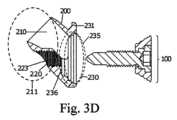
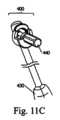
図3Aから図14Dは、第1の医療締結装置(1)の実施形態を示す。具体的には、医療締結装置(1)は、第1の締結要素(100)および第2の締結要素(200)を備える。記載される例のいずれにおいても、第2の締結要素(200)は締結フェルールであり得ることが観察されるはずである。First Fastening Device Figures 3A to 14D show an embodiment of a first medical fastening device (1). In particular, the medical fastening device (1) comprises a first fastening element (100) and a second fastening element (200). It should be observed that in any of the described examples, the second fastening element (200) can be a fastening ferrule.
第1の締結装置:第1の締結要素(100)
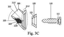
第1の発明による第1の締結要素(100)の実施形態が、図3Aから図3Dにおいて観察され得る。この例では、第1の締結要素は、アレンタイプの作動領域が設けられたヘッドと、第2の導管(220)のねじ山(223)に対して相補的なねじ山(113)とを有する、締結ねじ(110)である。First fastening device: first fastening element (100)
An embodiment of the first fastening element (100) according to the first invention can be seen in figures 3A to 3D. In this example, the first fastening element is a fastening screw (110) having a head provided with an Allen-type working area and a thread (113) complementary to the thread (223) of the second conduit (220).
さらに、第1の締結要素(100)は、使用時にねじのヘッドを包囲するワッシャ(120)を備える。Furthermore, the first fastening element (100) includes a washer (120) that surrounds the head of the screw in use.
図3Aから図3Dは、ねじ(110)およびワッシャ(120)の図を示す。具体的には、ねじのヘッドは、ワッシャ(120)の内表面の形状に対して相補的である。この実施形態では、ねじ(110)は、ねじの軸に対して垂直な平面内に、円形段差(111)を備える。そして、ワッシャ(120)内には相補的な方法で、ねじのものとは反対の内側円形段差(121)が設けられている。有利には、この例は、ワッシャとねじとの係合が崩れるのを防止し、これにより、ワッシャをねじと整合させたまま維持することを可能にし、両者間の力の伝達を最適化する。3A to 3D show views of a screw (110) and a washer (120). In particular, the head of the screw is complementary to the shape of the inner surface of the washer (120). In this embodiment, the screw (110) has a circular step (111) in a plane perpendicular to the axis of the screw, and in the washer (120) is provided in a complementary manner an inner circular step (121) opposite to that of the screw. Advantageously, this example prevents the washer from losing engagement with the screw, thereby allowing the washer to remain aligned with the screw and optimizing the transfer of forces between them.
第1の締結装置:第2の締結要素(200)の第1の実施形態:図3Aから図5B
図3Aから図5Bは、第1の医療締結装置(1)の第1の実施形態を示す。具体的には、第2の締結要素(200)は、第1の縦軸(215)に沿って延在する第1の貫通導管(210)を備える。図3Cおよび図3Dの断面図に見られるように、第2の締結要素(200)は、第1の端部(211)および第2の端部(212)をさらに備える。First fastening device: First embodiment of the second fastening element (200): FIGS. 3A to 5B
Figures 3A to 5B show a first embodiment of a first medical fastening device (1). Specifically, the second fastening element (200) comprises a first through conduit (210) extending along a first longitudinal axis (215). As can be seen in the cross-sectional views of Figures 3C and 3D, the second fastening element (200) further comprises a first end (211) and a second end (212).
第2の締結要素(200)の第1の貫通導管(210)に関連して、図3Aおよび図3Bは、前記貫通導管(210)が第1の端部(211)および第2の端部(212)をさらに備えることを示している。具体的には、第1の貫通導管(210)は、図5Aから図5B、図14Aから図14Dに示される使用方法の説明において以下に示されるように、移植片(10)を収容するように構成されている。具体的には、第1の端部(211)は移植片(10)を受容するように意図され、第2の端部(212)は、図5Aおよび図5Bに示されるように環状締結通路(300)の締結面の一部となるように意図される。With respect to the first through-conduit (210) of the second fastening element (200), Figs. 3A and 3B show that said through-conduit (210) further comprises a first end (211) and a second end (212). In particular, the first through-conduit (210) is configured to accommodate an implant (10), as shown below in the description of the method of use shown in Figs. 5A-5B, 14A-14D. In particular, the first end (211) is intended to receive the implant (10), and the second end (212) is intended to be part of the fastening surface of the annular fastening passage (300), as shown in Figs. 5A and 5B.
第2の締結要素(200)の第1の導管(210)の遠位端の構成は、円形、楕円形、矩形、三葉状(trilobular)、半環状であり得、または必ずしも遠位端と近位端との構成間に対応を有することなく、先端技術で既知のその他いずれかの幾何形状に対応することが可能である。The configuration of the distal end of the first conduit (210) of the second fastening element (200) may be circular, elliptical, rectangular, trilobular, semi-annular, or correspond to any other geometric shape known in the state of the art, without necessarily having a correspondence between the configurations of the distal and proximal ends.
さらに、図3Aから図3Dに見られるように、第2の締結要素(200)は、第2の縦軸(225)に沿って延在する第2の締結導管(220)を備える。第2の締結導管(220)は、第1の端部(221)および第2の端部(222)をさらに備える。Further, as seen in Figures 3A-3D, the second fastening element (200) comprises a second fastening conduit (220) extending along a second longitudinal axis (225). The second fastening conduit (220) further comprises a first end (221) and a second end (222).
第2の締結導管(220)は、図3Aから図5Bに見られるように、第1の締結要素(100)を収容および締結するように構成されている。この目的のために、第2の締結導管(220)は、第1の締結要素(100)のタイプの形態に応じてその内面にいくつかの形態を有することができる。たとえば、図3Cの断面図では、第2の締結導管(220)の内面は、ねじのねじ山と相補的なねじ山の形態を有する。別の実施形態では、第2の導管(220)の内面は、第1の締結要素(100)の外表面と相補的なクリップまたは板ばねの形態である。別の実施形態では、第2の締結導管(220)の内面は、第1のセルフタッピング締結要素(100)のための滑らかな形態を有する。The second fastening conduit (220), as seen in Figures 3A to 5B, is configured to receive and fasten the first fastening element (100). To this end, the second fastening conduit (220) can have several configurations on its inner surface depending on the configuration of the type of first fastening element (100). For example, in the cross-sectional view of Figure 3C, the inner surface of the second fastening conduit (220) has a thread configuration complementary to the thread of a screw. In another embodiment, the inner surface of the second fastening conduit (220) is in the form of a clip or leaf spring complementary to the outer surface of the first fastening element (100). In another embodiment, the inner surface of the second fastening conduit (220) has a smooth configuration for the first self-tapping fastening element (100).
図3Cの断面図の例に見られるように、第1の貫通導管(210)および第2の締結導管(220)は、第1の縦軸(215)および第2の縦軸(225)が互いに対して0以外の角度(α)、好ましくは0°から90°の角度を画定するように、第2の締結要素(200)の内部に配置される。好ましくは、角度(α)は30°から60°の間である。好ましくは、これらの実施形態では、角度(α)は45°であり得る。As seen in the cross-sectional example of FIG. 3C, the first through conduit (210) and the second fastening conduit (220) are disposed within the second fastening element (200) such that the first longitudinal axis (215) and the second longitudinal axis (225) define a non-zero angle (α) with respect to one another, preferably an angle between 0° and 90°. Preferably, the angle (α) is between 30° and 60°. Preferably, in these embodiments, the angle (α) may be 45°.
具体的には、図3Aは、第2の締結要素(200)が、第2の締結要素(200)の第2の端部(212)に近位空洞(235)を画定する環状近位表面(230)を備えることを示している。さらに、第1の貫通導管(210)の第2の端部(212)および第2の締結導管(220)の第2の端部(222)は接合されて、近位空洞(235)の底部に接合部(290)を画定する。接合部(290)、第1の貫通導管(210)の第2の端部(212)、および第2の締結導管(220)の第2の端部(222)は、前記近位空洞(235)の開口部まで延在する第2の締結要素(200)の第2の端部(212)の近位空洞(235)の底部の一部である。Specifically, FIG. 3A shows that the second fastening element (200) comprises an annular proximal surface (230) that defines a proximal cavity (235) at the second end (212) of the second fastening element (200). Furthermore, the second end (212) of the first through conduit (210) and the second end (222) of the second fastening conduit (220) are joined to define a junction (290) at the bottom of the proximal cavity (235). The junction (290), the second end (212) of the first through conduit (210), and the second end (222) of the second fastening conduit (220) are part of the bottom of the proximal cavity (235) at the second end (212) of the second fastening element (200) that extends to the opening of said proximal cavity (235).
さらに、この実施形態では接合部(290)が可動であることが、図4Bに見られる。Furthermore, it can be seen in FIG. 4B that in this embodiment, the joint (290) is movable.
図3Dの実施形態に見られるように、第2の締結要素(200)の環状近位表面(230)上には下部停止部(236)がある。したがって、環状近位表面(230)は下部停止部(236)を備える。環状近位表面(230)と停止部(236)との組み合せにより、第1の締結要素(100)の輪郭のセクタが下部停止部(236)上に支持される最大締め付けの位置が存在でき、これは装置によって提供される締結の剛性を有利に向上させる。As can be seen in the embodiment of FIG. 3D, the annular proximal surface (230) of the second fastening element (200) has a lower stop (236) on it. Thus, the annular proximal surface (230) comprises a lower stop (236). The combination of the annular proximal surface (230) and the stop (236) allows a position of maximum tightening to exist where a sector of the contour of the first fastening element (100) rests on the lower stop (236), which advantageously increases the stiffness of the fastening provided by the device.
停止部(236)は、所定の厚さへの移植片の締結を可能にし、締結に剛性を提供する。環状近位表面(230)の環状構成は、開始厚さから締結装置(1)の最大締め付けの位置に対応するこの所定の厚さまでの移植片(10)の膨張のために十分な空間を確保する。The stop (236) allows fastening of the graft to a predetermined thickness and provides rigidity to the fastening. The annular configuration of the annular proximal surface (230) ensures sufficient space for expansion of the graft (10) from the starting thickness to this predetermined thickness, which corresponds to the position of maximum tightening of the fastening device (1).
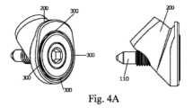
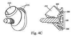
図3Aから図5Bの実施形態に見られるように、第2の締結要素は、骨孔内への装置(1)の移動を有利に防止するフランジ(231)を備える。As seen in the embodiment of Figures 3A to 5B, the second fastening element includes a flange (231) that advantageously prevents migration of the device (1) into the bone hole.
最後に、図4Aから図5Bは、第2の締結要素(200)の第1の実施形態の第2の締結導管(220)内に収容および締結された第1の締結要素(100)を有する実施形態を示す。環状近位表面(230)の内面とワッシャ(120)の外表面との間に環状締結通路(300)が形成される様子が見られる。Finally, Figures 4A-5B show an embodiment having a first fastening element (100) received and fastened within a second fastening conduit (220) of a first embodiment of a second fastening element (200). An annular fastening passage (300) can be seen formed between the inner surface of the annular proximal surface (230) and the outer surface of the washer (120).
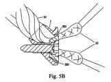
図5Aおよび図5Bは、少なくとも1つの移植片(10)が内部に拘束された医療締結装置の、上部分全体の図および下部分の断面図をそれぞれ示す。具体的には、本発明の医療締結装置(1)によって作成された環状締結通路(300)が、図5Bにはっきりと見られる。前記環状締結通路(300)は、環状近位表面(230)の配置が近位空洞(235)の連続的で環状の表面を生成するので、環状である。これにより、環状近位表面(230)を環状締結通路(300)の一部とすることができ、これにより、先端技術で述べられた要素よりも大きな締結通路を用いていくつかの移植片を締結させることができる。さらに、環状締結通路(300)の形状は、締結とのより大きな構造的一貫性を提供する。5A and 5B show a top overall view and a bottom cross-sectional view, respectively, of a medical fastening device with at least one implant (10) constrained therein. In particular, the annular fastening channel (300) created by the medical fastening device (1) of the present invention is clearly seen in FIG. 5B. Said annular fastening channel (300) is annular because the arrangement of the annular proximal surface (230) creates a continuous, annular surface of the proximal cavity (235). This allows the annular proximal surface (230) to be part of the annular fastening channel (300), which allows several implants to be fastened using a larger fastening channel than the elements described in the state of the art. Furthermore, the shape of the annular fastening channel (300) provides greater structural consistency with the fastener.
図5Aおよび図5Bが図1Aから図1Fと比較された場合、先端技術の他の装置(600、700、800)に対する本発明の医療締結装置(1)の違いが明確に見られる。図1Aおよび図1Bの干渉ねじ(600)は、骨に対する締結を実行し、前記骨(900)の多孔性のため、これは非常に弱い締結である。さらに、前記干渉ねじ(600)が靱帯を損傷し、締結をさらに弱める可能性があることがわかる。When Figures 5A and 5B are compared with Figures 1A to 1F, the difference of the medical fastening device (1) of the present invention with respect to other devices (600, 700, 800) of the state of the art can be clearly seen. The interference screw (600) of Figures 1A and 1B performs fastening against the bone, which is a very weak fastening due to the porosity of said bone (900). Furthermore, it can be seen that said interference screw (600) may damage the ligament, further weakening the fastening.
図1Cおよび図1Dのねじ(700)は、移植片上に直接、移植片を収容するフェルール内に同軸にねじ込まれ、これは干渉ねじと同様に、前記移植片を損傷する可能性がある。さらに、脛骨で使用する場合、ねじのヘッドの最大部分は脛骨内に収容され、これはこの骨の高い多孔性のため、装置の移動に対する抵抗を弱める。The screw (700) of Figures 1C and 1D is threaded coaxially directly onto the implant into a ferrule that houses the implant, which, like an interference screw, can damage the implant. Furthermore, when used in the tibia, the largest portion of the head of the screw is housed within the tibia, which reduces resistance to device migration due to the high porosity of this bone.
図1Eから図1Fの拘束要素(800)は、骨孔内に導入され、孔の内壁に対して移植片を拘束し、同時に、腓骨室に対して垂直に浸入し、拘束要素の傾斜面にねじ込まれる、ワッシャを有するねじ(802)が、移植片をもう一度拘束する。この構成は、ワッシャを有するねじの周りに締結領域を配置するので、ねじは、その締結に進むために必然的に移植片の束の間を分離して通過しなければならず、これにより、発明の背景に記載されたこれらの装置に関連する他の問題を引き起こすことに加えて、2つの従来技術の例のように、移植片を損傷する可能性がある。The constraining element (800) of Figures 1E-1F is introduced into the bone hole and constrains the graft against the inner wall of the hole, while the screw (802) with the washer, which penetrates perpendicularly to the fibular chamber and is screwed into the inclined surface of the constraining element, constrains the graft once again. Since this configuration places the fastening area around the screw with the washer, the screw must necessarily separate and pass between the bundles of the graft to proceed to fasten it, which can damage the graft as in the two prior art examples, in addition to causing other problems associated with these devices described in the background of the invention.
対照的に、第1の医療締結装置(1)は、第1の縦軸(215)および第2の縦軸(225)が互いに対して0以外の角度(α)を画定するように、第1の導管(210)および第2の導管(220)が第2の締結要素(200)の内部に配置されるという事実のため、ねじ(110)で靱帯を損傷するのを防止する。さらに、第1の医療締結装置(1)と同様に、靱帯は、環状近位表面(230)の助けを借りてその中に収容され、より大きい締結通路(300)が得られ、多孔質骨(900)に対する締結が防止されて、より強力でより耐久性のある締結を提供する。In contrast, the first medical fastening device (1) prevents the screw (110) from damaging the ligament due to the fact that the first conduit (210) and the second conduit (220) are disposed within the second fastening element (200) such that the first longitudinal axis (215) and the second longitudinal axis (225) define a non-zero angle (α) with respect to each other. Furthermore, similar to the first medical fastening device (1), the ligament is contained therein with the aid of the annular proximal surface (230), resulting in a larger fastening passage (300) and preventing fastening against the porous bone (900), providing a stronger and more durable fastening.
フェルールの上部近位領域のみの締結通路の構成は、図2Eに見られる。図2Eが図5Aおよび図5Bと比較された場合、図2Eは、移植片(10)の一部を拘束されないままにする制限された締結通路を提供するが、装置が大きすぎるのでなければ、これは締結の安定性および装置によって提供される極限引張強度の両方を低下させ、許容可能な解決策ではない。A fastening passage configuration in only the upper proximal region of the ferrule is seen in FIG. 2E. When FIG. 2E is compared to FIG. 5A and FIG. 5B, FIG. 2E provides a limited fastening passage that leaves a portion of the graft (10) unconstrained, however, unless the device is too large, this reduces both the fastening stability and the ultimate tensile strength provided by the device and is not an acceptable solution.
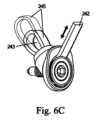
第1の締結装置:第2の締結要素(200)の第2の実施形態:調整可能ループ(245)を構成する遠位付属物(240):図6Aから図6D
図6Aから図6Dは、本発明の第1の医療締結装置(1)の第2の実施形態を示す。見てわかるように、第2の実施形態は、第2の実施形態が調整可能ループ(245)を構成する遠位付属物(240)をさらに備えることを除いて、第1の実施形態と同様である。First fastening device: Second embodiment of the second fastening element (200): Distal appendage (240) constituting an adjustable loop (245): Figs. 6A to 6D
Figures 6A to 6D show a second embodiment of the first medical fastening device (1) of the present invention. As can be seen, the second embodiment is similar to the first embodiment, except that the second embodiment further comprises a distal appendage (240) that defines an adjustable loop (245).
図6Aに見られるように、遠位付属物(240)は、第1の端部(241)が第2の締結要素(200)の第1の端部と接合し、第2の端部(242)が第1の締結自由位置を有する、ストリップ、コード、またはバンドを備える。第2の位置では、図6B、図6C、および図6Dに示されるように、第2の端部(242)は、前記端部(242)が第1の締結要素(100)によって所望の位置に締結される調整可能ループ(245)を構成する第2の締結要素(200)に戻るように、構成されることが可能である。As seen in FIG. 6A, the distal appendage (240) comprises a strip, cord, or band having a first end (241) that joins with a first end of the second fastening element (200) and a second end (242) that has a first fastening free position. In the second position, as shown in FIGS. 6B, 6C, and 6D, the second end (242) can be configured to return to the second fastening element (200) forming an adjustable loop (245) where said end (242) is fastened in a desired position by the first fastening element (100).
具体的には、図6Bから図6Dに示されるように、第1の締結要素(100)が第2の締結要素(200)の第2の締結導管(220)内に収容および締結されると、自由端(242)もまた前記締結通路(300)内に締結される。Specifically, as shown in Figures 6B to 6D, when the first fastening element (100) is received and fastened within the second fastening conduit (220) of the second fastening element (200), the free end (242) is also fastened within said fastening passage (300).
図6Cに見られるように、点線は、調整可能ループ(245)が取ることができる異なる位置の一例を示し、したがって、遠位付属物(240)は可撓性であり、この実施形態において1つ以上の最終位置を画定することができると見なされ得る。As seen in FIG. 6C, the dotted lines show an example of different positions that the adjustable loop (245) can assume, and thus the distal appendage (240) can be considered flexible and capable of defining one or more final positions in this embodiment.
調整可能ループ(245)の長さは第1の締結要素(100)によって締結され、調整可能ループ(245)は、骨孔または骨管内の移植片(10)の屈曲端の吊りを意図している。前記締結は、張力のない第1の位置から、吊られた移植片の理想的な張力を有する最終位置まで調整可能である。The length of the adjustable loop (245) is fastened by the first fastening element (100), and the adjustable loop (245) is intended for hanging the bent end of the graft (10) in a bone hole or canal. The fastening is adjustable from a first position with no tension to a final position with ideal tension in the suspended graft.
第1の締結装置:第2の締結要素(200)の第3の実施形態:締結されたループを構成する遠位付属物(250):図7Aから図7C
図7Aから図7Cは、本発明の第1の医療締結装置(1)の第3の実施形態を示す。見てわかるように、第3の実施形態は、第3の実施形態は非調整可能ループを構成する穴(253)を有する遠位付属物(250)をさらに備えることを除いて、第1の実施形態と同様である。これは、付属物(250)の両端(251、252)が第2の締結要素(200)に締結されており、したがって吊りの領域、すなわち穴(253)のサイズが一定であるため、締結または非調整可能ループと呼ばれることが可能である。一実施形態では、遠位付属物(250)は可撓性である。図7Aから図7Cの例では、遠位付属物(250)は垂直位置にある。First fastening device: third embodiment of the second fastening element (200): distal appendage (250) constituting a fastened loop: Figs. 7A to 7C
Figures 7A to 7C show a third embodiment of the first medical fastening device (1) of the present invention. As can be seen, the third embodiment is similar to the first embodiment, except that the third embodiment further comprises a distal appendage (250) with a hole (253) constituting a non-adjustable loop. This can be called a fastening or non-adjustable loop, since both ends (251, 252) of the appendage (250) are fastened to the second fastening element (200), and therefore the area of suspension, i.e. the size of the hole (253), is constant. In one embodiment, the distal appendage (250) is flexible. In the example of Figures 7A to 7C, the distal appendage (250) is in a vertical position.
この特定の実施形態に見られるように、遠位付属物(250)は、骨孔内の移植片の屈曲端の吊りを意図した閉または非調整可能ループが構成されるように、両端(251、252)が第2の締結要素(200)に接合された、ストリップ、コード、またはバンドを備える。As seen in this particular embodiment, the distal appendage (250) comprises a strip, cord, or band with both ends (251, 252) joined to the second fastening element (200) so as to form a closed or non-adjustable loop intended for suspending the bent end of the graft within the bone tunnel.
第1の締結装置:第2の締結要素(200)の第4の実施形態:吊り用の穴を有する遠位付属物(260,270):図8Aから図9D
図8Aから図8Cは、本発明の第1の医療締結装置(1)の第4の実施形態を示す。見てわかるように、第4の実施形態は、第4の実施形態が遠位付属物(260)をさらに備えることを除いて、第1の実施形態と同様である。これらの例では、遠位付属物(260)は、骨孔内の移植片の屈曲端の吊りを意図した、穴(263)を画定する半リングである。First fastening device: Fourth embodiment of the second fastening element (200): Distal appendages (260, 270) with hanging holes: Figs. 8A to 9D
Figures 8A to 8C show a fourth embodiment of the first medical fastening device (1) of the present invention. As can be seen, the fourth embodiment is similar to the first embodiment, except that the fourth embodiment further comprises a distal appendage (260). In these examples, the distal appendage (260) is a half ring defining a hole (263) intended for suspending the bent end of the graft in the bone tunnel.
図9Aから図9Dの特定の実施形態では、第2の締結要素(200)はフランジ(231)を備えず、代わりに円錐台状の外部輪郭を有し、これは骨孔(10)の入口に装置を有利に保持して骨孔(10)を貫通するのを防止し、前記第2の締結要素(200)は、残りの態様に関して第1の発明の第1の実施形態に示されたものと同様である。In the particular embodiment of Figures 9A to 9D, the second fastening element (200) does not have a flange (231) but instead has a frustoconical outer contour, which advantageously holds the device at the entrance of the bone hole (10) and prevents it from penetrating the bone hole (10), and said second fastening element (200) is similar to that shown in the first embodiment of the first invention in the remaining aspects.
図9Cおよび図9Dの例に見られるように、遠位付属物(270)は、第1の端部(271)と、第2の締結要素(200)の第1の端部に位置する第2の端部(272)とを備える。さらに、遠位付属物(270)は、骨孔内の移植片の屈曲端の吊りを意図した穴(273)を備える。より具体的には、穴(273)は、遠位付属物(270)の第1の端部(271)に位置している。9C and 9D, the distal appendage (270) comprises a first end (271) and a second end (272) located at the first end of the second fastening element (200). Furthermore, the distal appendage (270) comprises a hole (273) intended for hanging the bent end of the graft in the bone hole. More specifically, the hole (273) is located at the first end (271) of the distal appendage (270).
別の実施形態では、図9Aから図9Dの第2の締結要素(200)は、図8Aから図8Dの例に示されるもののようなフランジ(231)を備えてもよい。In another embodiment, the second fastening element (200) of Figures 9A to 9D may include a flange (231) such as that shown in the example of Figures 8A to 8D.
図8Aから図9Dを見ると、遠位付属物(260、270)は水平位置にあると見なされ得る。Looking at Figures 8A through 9D, the distal appendages (260, 270) can be considered to be in a horizontal position.
第1の締結装置:第2の締結要素(200)の第5の実施形態:吊り用の穴(281)を有する遠位付属物(280):図10Aから図10DFirst fastening device: Fifth embodiment of the second fastening element (200): Distal appendage (280) with hanging hole (281): Figs. 10A to 10D
図10Aから図10Dは、本発明の第1の医療締結装置(1)の第5の実施形態を示す。見てわかるように、第5の実施形態は、第5の例が第2の締結要素(200)の第1の端部に位置する遠位付属物(280)をさらに備えることを除いて、第1の実施形態と同様である。これらの例では、遠位付属物(280)は、第1の端部(281)、第2の端部(282)、および骨孔内の移植片の屈曲端の吊りを意図した穴(283)を備える。さらに、穴(283)は、遠位付属物(280)の第1の端部(281)に位置している。10A to 10D show a fifth embodiment of the first medical fastening device (1) of the present invention. As can be seen, the fifth embodiment is similar to the first embodiment, except that the fifth example further comprises a distal appendage (280) located at the first end of the second fastening element (200). In these examples, the distal appendage (280) comprises a first end (281), a second end (282), and a hole (283) intended for hanging the bent end of the graft in the bone hole. Furthermore, the hole (283) is located at the first end (281) of the distal appendage (280).
図10Aから図10Dを見ると、遠位付属物(280)は垂直位置にあると見なされ得る。Looking at Figures 10A through 10D, the distal appendage (280) can be considered to be in a vertical position.
特定の方法で、第2の端部(282)は、第1の貫通導管(210)を2つのセクションに分割する第1の貫通導管(210)内に収容される。言い換えると、第1の貫通導管(210)は、遠位付属物(280)の第2の端部(282)によって第1のセクション(213)および第2のセクション(214)に分割される。In a particular manner, the second end (282) is received within the first through conduit (210) dividing the first through conduit (210) into two sections. In other words, the first through conduit (210) is divided into a first section (213) and a second section (214) by the second end (282) of the distal appendage (280).
一方、図10A、図10B、および図10Dは、遠位付属物(280)の第2の端部(282)が、近位空洞(235)の底部、および第1の貫通導管(210)の第2の端部(212)と第2の締結導管(220)の第2の端部(222)との間の接合部の一部であることを示している。Meanwhile, Figures 10A, 10B, and 10D show that the second end (282) of the distal appendage (280) is part of the bottom of the proximal cavity (235) and the junction between the second end (212) of the first through conduit (210) and the second end (222) of the second fastening conduit (220).
第1の締結装置:第2の締結要素(200)の第6の実施形態:吊り用の穴(293)を有する遠位付属物(290):図17Aから図17D
図17Aから図17Dは、本発明の第1の医療締結装置(1)の第6の実施形態を示す。見てわかるように、第6の実施形態は、第6の例の第2の締結導管(220)の第2の端部(222)が第2の縦軸(225)に対して垂直な軸上で反対側に位置する2つのフランジをさらに備えることを除いて、第1の実施形態と同様である。第1の実施形態とのもう1つの違いは、第6の例が、第2の締結要素(200)の第1の端部に位置する遠位付属物(290)を備えることである。First fastening device: Sixth embodiment of the second fastening element (200): Distal appendage (290) with hanging hole (293): Figs. 17A to 17D
17A to 17D show a sixth embodiment of the first medical fastening device (1) of the present invention. As can be seen, the sixth embodiment is similar to the first embodiment, except that the second end (222) of the second fastening conduit (220) of the sixth example further comprises two flanges located on opposite sides of an axis perpendicular to the second longitudinal axis (225). Another difference from the first embodiment is that the sixth example comprises a distal appendage (290) located at the first end of the second fastening element (200).
例では、2つのフランジ(231)は、骨孔内への入口開口部の外側上部分を区切る皮質骨に当接するように構成された環状保持ローブの形態である。In the example, the two flanges (231) are in the form of annular retaining lobes configured to abut the cortical bone that bounds the outer upper portion of the entrance opening into the bone hole.
有利には、フランジ(231)は、骨孔(10)の入口に装置を保持し、これが骨孔(10)を貫通するのを防止する。Advantageously, the flange (231) holds the device at the entrance to the bone hole (10) and prevents it from penetrating the bone hole (10).
例では、遠位付属物(290)は、骨孔内の移植片の屈曲端の吊りを意図した穴(293)を備える。In the example, the distal appendage (290) includes a hole (293) intended for suspending the bent end of the graft within the bone tunnel.
第1の締結装置:医療締結装置(1)を挿入するためのシステム(400):図11Aから図11E
図11Aから図11Eは、上記で示された実施形態のいずれかによる医療締結装置(1)を挿入するためのシステム(400)の実施形態を示す。システム(400)は、本発明の医療締結装置(1)、連結ねじ(440)、および第2の締結要素(200)の第2の端部と係合するように構成された第1の端部(410)とインサータ(450)の第2の端部(420)に位置するハンドル(430)とを有するインサータ(450)を備える。First fastening device: system (400) for inserting the medical fastening device (1): Figs. 11A to 11E
11A to 11E show an embodiment of a system (400) for inserting a medical fastening device (1) according to any of the embodiments shown above. The system (400) comprises a medical fastening device (1) of the present invention, a coupling screw (440), and an inserter (450) having a first end (410) configured to engage a second end of a second fastening element (200) and a handle (430) located at a second end (420) of the inserter (450).
有利には、連結ねじ(440)を有するインサータ(450)の使用は、ハンドル(430)を通じて装置を操作すること、および骨孔(11)への装置(1)の挿入に必要な力を印加することを可能にする。これにより、図11Aおよび図11Eでより詳細にわかるように、装置(1)がインサータ(450)から分離するのを防止する。Advantageously, the use of an inserter (450) with a connecting screw (440) allows for manipulation of the device through the handle (430) and application of the force required for insertion of the device (1) into the bone hole (11). This prevents the device (1) from becoming detached from the inserter (450), as can be seen in more detail in Figures 11A and 11E.
第1の締結装置:大腿骨内の調整可能ループおよび脛骨内の剛性の垂直な遠位付属物を有する医療締結装置の使用例:図12Aから図12D
図12Aから図12Dは、本発明の第1の医療締結装置(1)のうちの2つを使用する右膝(15)の前十字靱帯(ACL)の修復を示す。第1の医療締結装置(1)は、図6Aから図6Cの例に記載されたものと同様であり、第2の医療装置(1)は、穴のない、垂直位置の遠位付属物を備える。First fastening device: Example of use of a medical fastening device with an adjustable loop in the femur and a rigid vertical distal appendage in the tibia: Figs. 12A to 12D
Figures 12A to 12D show the repair of the anterior cruciate ligament (ACL) of a right knee (15) using two of the first medical fastening devices (1) of the present invention, the first medical fastening device (1) being similar to that described in the example of Figures 6A to 6C, the second medical device (1) being provided with a distal appendage in a vertical position without a hole.
有利には、穴のないこの遠位付属物は、ねじれが孔内セグメントに到達することなく、移植片枝の関節内セグメントのねじれを維持することを可能にし、これは、図12Aから図12Dの実施形態に見られるように、元のACLのねじれの解剖学的構造および生体力学を修復するために重要である。Advantageously, this non-perforated distal attachment allows for the torsion of the intra-articular segment of the graft branch to be maintained without the torsion reaching the intra-foraminal segment, which is important for restoring the torsional anatomy and biomechanics of the original ACL, as seen in the embodiment of Figures 12A-12D.
図12Aは、脛骨内にできた骨孔(12)から突出する移植片(10)の自由端を示す。移植片(10)の屈曲端は、第1の医療締結装置(1)の調整可能ループ(245)から吊られている。Figure 12A shows the free end of the graft (10) protruding from a bone tunnel (12) created in the tibia. The bent end of the graft (10) is suspended from an adjustable loop (245) of the first medical fastening device (1).
有利には、調整可能ループ(245)は、大腿骨骨孔(11)、または大腿骨骨管を形成すること、およびこれに嵌合するために移植片の屈曲端を引っ張ることを可能にし、これにより、移植片(10)が締結される張力を確認および調整することをさらに可能にする。Advantageously, the adjustable loop (245) allows the bent end of the graft to be tensioned to form and fit into the femoral bone hole (11), or femoral bone tunnel, thereby further allowing the tension at which the graft (10) is fastened to be confirmed and adjusted.
図12Bは、調整可能ループが大腿骨締結装置によって拘束された状態の、嵌合された後の移植片の屈曲端を示す。移植片(10)の自由端は、依然として脛骨内にできた骨孔(12)から突出している。Figure 12B shows the bent end of the implant after it has been fitted, with the adjustable loop constrained by the femoral fastener. The free end of the implant (10) still protrudes from the created bone tunnel (12) in the tibia.
図12Cは、図示される右膝のACLにおける、元のACLの、すなわち反時計回り方向の解剖学的ねじれ(16)特性を模倣する、移植片(10)の関節内セグメントのねじれを示す。有利には、図12Cに示される、遠位付属物を有して穴を有さない第2の医療装置(1)は、移植片の関節内セグメントに付与された解剖学的ねじれが制御不能に骨孔内に伝播しないように、移植片(10)の枝を分離したまま維持することを可能にする。見てわかるように、インサータシステム(400)は、装置を操作するために使用される。Figure 12C shows the twisting of the intra-articular segment of the graft (10) mimicking the anatomical twisting (16) characteristic of the native ACL, i.e., in a counterclockwise direction, in the ACL of the illustrated right knee. Advantageously, the second medical device (1) with distal attachment and no hole shown in Figure 12C allows the branches of the graft (10) to remain separated so that the anatomical twisting imparted to the intra-articular segment of the graft does not propagate uncontrollably into the bone hole. As can be seen, an inserter system (400) is used to operate the device.
図12Dは、移植片(10)が膝関節内の安定性を回復するために必要な張力で張られた後の、第1のねじ切り締結要素(100)を有する締結装置(1)を示す。Figure 12D shows the fastening device (1) with the first threaded fastening element (100) after the implant (10) has been tensioned to the required tension to restore stability within the knee joint.
第1の締結装置:本発明の第1の医療締結装置(1)の使用例:移植片の3本鎖構成:図13Aから図13D
図13Aは、右膝のACLの修復における、本発明の2つの第1の医療装置(1)の共同使用の図を示し、前記使用は、以下を備える。
-3つの枝で構成された移植片(10)に、2つの屈曲端および2つの自由端を提供するステップと、
-それぞれの第1および第2の骨孔(11、12)に導入されるように意図された、穴を有する遠位付属物(250、260、270、280)を2つの医療締結装置(1)に提供するステップ。第1の締結要素(100)および第2の締結要素(200)の組立体は、図13Aに矩形として描写されている。穴(253、263、273、283)は、図13Aに円として描写されている。
-図13Bから図13Dに示されるように、第1の自由端を締結し、第1の骨孔(11)に挿入された第1の医療装置(1)によって移植片(10)の第1の屈曲端を吊ることを可能にするように、2つの医療締結装置(1)を構成するステップ。一方、第2の自由端を締結し、第2の骨孔に挿入された第2の医療装置(1)によって移植片(10)の第2の屈曲端を吊るステップ。First fastening device: Example of use of the first medical fastening device (1) of the present invention: Three-strand configuration of the graft: Figs. 13A to 13D
FIG. 13A shows a diagram of the joint use of two first medical devices (1) of the present invention in the repair of the ACL of the right knee, said use comprising:
- providing a three-pronged graft (10) with two bent ends and two free ends;
- providing two medical fastening devices (1) with distal appendages (250, 260, 270, 280) with holes intended to be introduced into the respective first and second bone holes (11, 12). The assembly of the first fastening element (100) and the second fastening element (200) is depicted as a rectangle in Fig. 13A. The holes (253, 263, 273, 283) are depicted as circles in Fig. 13A.
- configuring the two medical fastening devices (1) to fasten the first free end and allow suspending a first bent end of the graft (10) by a first medical device (1) inserted in a first bone hole (11), as shown in figures 13B to 13D, while fastening the second free end and suspending a second bent end of the graft (10) by a second medical device (1) inserted in a second bone hole.
図13Bから図13Dは、図13Aの図による、単一の移植片の3本鎖構成用の図9Aから図9Dに示されるもののような2つの医療締結装置(1)の使用を示す。Figures 13B to 13D show the use of two medical fastening devices (1) such as those shown in Figures 9A to 9D for a three-strand configuration of a single graft according to the diagram of Figure 13A.
第1の締結装置:第1の発明の医療締結装置(1)の使用例:移植片の4本鎖構成:図14Aから図14C
図14Aは、右膝のACLの修復における本発明の2つの第1の医療装置(1)の使用図を示し、前記使用は、以下を備える。
-4つの枝の4本鎖構成を有する移植片(10)に、3つの屈曲端および2つの自由端を提供するステップと、
-2つの医療締結装置(1)を提供するステップであって、第1の装置は、第1の骨孔(11)内に導入されるように意図された、図10Aから図10Dの、穴(280)を有する垂直な遠位付属物を有し、第2の装置は、第2の骨孔(12)内に導入されるように意図された調整可能ループを有する、ステップ。第1の締結要素(100)および第2の締結要素(200)の組立体は、図14Aに矩形として描写されている。吊り要素、すなわち、穴または調整可能ループは、図14Aに円として描写されている。
-図14Bおよび図14Cに示されるように、両方の自由端を締結し、同時に第1の骨孔(11)に挿入された第1の医療装置(1)によって移植片(10)の第1の屈曲端を吊ることを可能にするように、2つの医療締結装置(1)を構成するステップ。一方、第2の骨孔(12)に挿入された第2の医療装置(1)によって、調整可能な方法で、移植片(10)の第2および第3の屈曲端を吊るステップ。First fastening device: Example of use of the medical fastening device (1) of the first invention: Four-stranded construction of the graft: Figures 14A to 14C
FIG. 14A shows a diagram of the use of the two first medical devices (1) of the present invention in repairing the ACL of a right knee, said use comprising:
- providing a graft (10) having a four-strand configuration of four branches, three bent ends and two free ends;
- providing two medical fastening devices (1), the first having a vertical distal appendage with a hole (280) of figures 10A to 10D, intended to be introduced into a first bone hole (11), and the second having an adjustable loop intended to be introduced into a second bone hole (12). The assembly of the first fastening element (100) and the second fastening element (200) is depicted as a rectangle in figure 14A. The suspension element, i.e. the hole or the adjustable loop, is depicted as a circle in figure 14A.
- configuring two medical fastening devices (1) to fasten both free ends and at the same time allow suspending a first bent end of the graft (10) by a first medical device (1) inserted in a first bone hole (11), as shown in figures 14B and 14C, while suspending, in an adjustable manner, the second and third bent ends of the graft (10) by a second medical device (1) inserted in a second bone hole (12).
第2の締結装置
図15Aから図16Dは、本発明の第2の医療締結装置(500)の実施形態を示す。具体的には、医療締結装置(500)は、第1の締結要素(510)と、締結導管(523)および吊り要素を備える第2の締結要素(520)とを備える。この第2の締結装置(500)では、第1の締結要素(510)が第2の締結要素(520)の締結導管(523)に締結され、骨孔内に導入されると、第2の締結要素(520)と、骨孔内に移植片を締結する前記骨孔との間に、または第1の締結要素(510)と装置自体に移植片を締結する第2の締結要素(520)との間に、締結通路が形成される。Second Fastening Device Figures 15A to 16D show an embodiment of a second medical fastening device (500) of the present invention. Specifically, the medical fastening device (500) comprises a first fastening element (510) and a second fastening element (520) comprising a fastening conduit (523) and a suspension element. In this second fastening device (500), when the first fastening element (510) is fastened to the fastening conduit (523) of the second fastening element (520) and introduced into a bone tunnel, a fastening passage is formed between the second fastening element (520) and the bone tunnel fastening the graft in said tunnel or between the first fastening element (510) and the second fastening element (520) fastening the graft to the device itself.
第2の締結装置:第1の締結要素(510)
第2の締結装置による第1の締結要素(510)の実施形態が、図15Aから図16Dにおいて観察され得る。図15A、図15C、および図15Dの例では、第1の締結要素(510)は、そのヘッドがそのシャンク(514)と同じ直径を有するねじである。図15Bの例では、ねじのヘッドの直径は、そのシャンク(514)の直径よりも大きい。ねじ(511)のヘッドにはアレンタイプの作動領域(512)が設けられ、そのシャンク(514)はねじ山を備える。Second fastening system: first fastening element (510)
An embodiment of a first fastening element (510) according to the second fastening device can be seen in Figures 15A to 16D. In the examples of Figures 15A, 15C and 15D, the first fastening element (510) is a screw whose head has the same diameter as its shank (514). In the example of Figure 15B, the diameter of the head of the screw is greater than the diameter of its shank (514). The head of the screw (511) is provided with an Allen-type working area (512) and its shank (514) is provided with a thread.
第2の締結装置:第2の締結要素(520)の第1の実施形態:図15Aから図15Cおよび図16Aから図16D
図15Aから図15Cおよび図16Aから図16Dは、本発明の第2の医療締結装置(500)の第1の実施形態を示す。図15Aから図15Cおよび図16Aから図16Dの例において明確にするために、第2の締結要素(520)は第1の端部(521)および第2の端部(522)を有し、さらに、第2の締結要素(520)は、第1の締結要素(510)を収容するように意図されたその第2の端部(522)に位置する締結導管(523)を備えることが、示されている。Second fastening device: First embodiment of the second fastening element (520): FIGS. 15A to 15C and 16A to 16D
Figures 15A to 15C and 16A to 16D show a first embodiment of a second medical fastening device (500) of the present invention. For the sake of clarity in the examples of Figures 15A to 15C and 16A to 16D, it is shown that the second fastening element (520) has a first end (521) and a second end (522), and further that the second fastening element (520) comprises a fastening conduit (523) located at its second end (522) intended to receive the first fastening element (510).
見てわかるように、第2の締結要素(520)は、骨孔内の移植片の屈曲端の吊りを意図した非調整可能穴または閉ループ(533)が構成されるように、第2の締結要素(520)の第1の端部(521)に接続された第1の端部(531)および第2の端部(532)を有する、吊り要素を構成する遠位付属物(530)を備える。As can be seen, the second fastening element (520) comprises a distal appendage (530) constituting a hanging element having a first end (531) and a second end (532) connected to the first end (521) of the second fastening element (520) such that a non-adjustable hole or closed loop (533) intended for hanging the bent end of the graft in the bone hole is formed.
有利には、図15Aから図15Cおよび図16Aから図16Dの装置は、第1の発明に記載されるものと同様の使用方法によって、移植片の3本鎖構成である図13Aおよび移植片の4本鎖構成である図14Aの図を再現することを可能にする。Advantageously, the devices of Figs. 15A-15C and Figs. 16A-16D make it possible to reproduce the diagrams of Fig. 13A, which shows a three-stranded configuration of the graft, and Fig. 14A, which shows a four-stranded configuration of the graft, by a method of use similar to that described in the first invention.
第2の締結装置:調整可能ループを構成する第2の締結要素(520)の第2の実施形態:図15D
図15Dは、本発明の第2の医療締結装置(500)の第2の実施形態を示す。見てわかるように、第2の実施形態は、遠位付属物(530)が調整可能ループ(533)として構成されていることを除いて、第1の実施形態と同様である。Second fastening device: second embodiment of the second fastening element (520) constituting an adjustable loop: FIG. 15D
15D illustrates a second embodiment of the second medical fastening device (500) of the present invention. As can be seen, the second embodiment is similar to the first embodiment, except that the distal appendage (530) is configured as an adjustable loop (533).
図15Dに見られるように、この特定の実施形態では、遠位付属物(530)は、第1の端部(531)が第2の締結要素(520)の第1の端部(521)および第2の締結自由端(532)に接続された、ストリップ、コード、またはバンドを備える。第2の端部(532)は、図15Dに示されるように、調整可能ループ(533)を構成する第2の締結要素(520)に戻るように構成されることが可能である。As seen in FIG. 15D, in this particular embodiment, the distal appendage (530) comprises a strip, cord, or band with a first end (531) connected to the first end (521) of the second fastening element (520) and a second fastening free end (532). The second end (532) can be configured to return to the second fastening element (520) forming an adjustable loop (533), as shown in FIG. 15D.
調整可能ループの長さは第1の締結要素(510)によって締結され、調整可能ループ(533)は、骨孔または骨管内の移植片(10)の屈曲端の吊りを意図している。前記締結は、張力のない第1の位置から、吊られた移植片の理想的な張力を有する最終位置まで調整可能である。The length of the adjustable loop is fastened by a first fastening element (510), and the adjustable loop (533) is intended for hanging the bent end of the graft (10) in a bone hole or canal. The fastening is adjustable from a first position with no tension to a final position with ideal tension in the suspended graft.
外科的方法:第1および第2の締結装置(1)による損傷した前十字靱帯(ACL)の修復:図18A~図18D
図18A~図18Dには、損傷した前十字靱帯(ACL)を修復するための外科的方法の一例が示されている。この外科的方法では、ACLの修復は、吊り穴(273)を有する第1および第2の締結装置(1)によって実行される。Surgical method: Repair of a torn anterior cruciate ligament (ACL) with a first and second fastening device (1): Figures 18A-18D
18A-18D show an example of a surgical method for repairing a torn anterior cruciate ligament (ACL), in which the repair of the ACL is performed with first and second fastening devices (1) having suspension holes (273).
有利には、骨孔(脛骨および大腿骨骨孔)の各々のための吊り穴(273)を装置(1)に設けることにより、図18B、図18C、および図18Dに示されるように、いずれの場合も、移植片(10)が吊られる反対側に配置された装置(1)を用いて各移植片(10)の自由端を締結するために、骨孔の一方に第1の移植片(10)を吊り、締結するために反対の骨孔に第2の移植片(10)を吊ることを可能にする。Advantageously, the device (1) is provided with a hanging hole (273) for each of the bone holes (tibial and femoral), making it possible to hang a first graft (10) in one of the bone holes and hang a second graft (10) in the opposite bone hole for fastening, in each case with the device (1) placed on the opposite side to which the graft (10) is hung, as shown in Figures 18B, 18C and 18D.
外科的方法は、
1)元のACLの挿入部位の大腿骨骨孔の関節内進入口を用いて、大腿骨骨孔を実施するステップと、
2)元のACLの挿入部位の脛骨骨孔の関節内進入口を用いて、脛骨骨孔を実施するステップと、
3)第1の締結装置(1)の吊り穴(273)から、第1の移植片(10)の屈曲端を吊るステップと、
4)第1の移植片(10)の自由端が脛骨骨孔の関節外進入口から突出するまで、膝関節の関節内空洞を通じて脛骨骨孔の関節内進入口に到達するまでの大腿骨骨孔の関節外進入口を通じて第1の移植片(10)の自由端を導入するステップと、
5)第2の締結装置(1)の吊り穴(273)から、第2の移植片(10)の屈曲端を吊るステップと、
6)第2の移植片(10)の自由端が大腿骨骨孔の関節外進入口から突出するまで、膝関節の関節内空洞を通じて大腿骨骨孔の関節内進入口に到達するまでの大腿骨骨孔の関節外進入口を通じて第2の移植片(10)の自由端を導入するステップと、
を備え、
図18Cおよび図18Dに示されるように、自由端の各々が、移植片(10)が吊られる反対側に締結された装置(1)によって締結され得るように、第1および第2の移植片(1)の自由端は関節外脛骨および大腿骨進入口内に配置される。 The surgical method is
1) performing a femoral tunnel using the intra-articular entrance of the femoral tunnel at the original ACL insertion site;
2) performing a tibial tunnel using the intra-articular access of the tibial tunnel at the insertion site of the original ACL;
3) suspending the bent end of the first graft (10) from the suspension hole (273) of the first fastening device (1);
4) introducing the free end of the first graft (10) through the extra-articular entrance of the femoral tunnel through the intra-articular cavity of the knee joint until the free end of the first graft (10) protrudes from the extra-articular entrance of the tibial tunnel and reaches the intra-articular entrance of the tibial tunnel;
5) suspending the bent end of the second graft (10) from the suspension hole (273) of the second fastening device (1);
6) introducing the free end of the second graft (10) through the extra-articular entrance of the femoral tunnel through the intra-articular cavity of the knee joint until the free end of the second graft (10) protrudes from the extra-articular entrance of the femoral tunnel and reaches the intra-articular entrance of the femoral tunnel;
Equipped with
As shown in Figures 18C and 18D, the free ends of the first and second implants (1) are positioned within the extra-articular tibial and femoral access portals so that each of the free ends can be fastened by a fastening device (1) on the opposite side to which the implant (10) is suspended.
この構成は、追加的に、図18Cおよび図18Dに示されるように、移植片の関節内セグメントが、元のACLの生体力学の特性である解剖学的ねじれで構成されるように、両方の移植片をねじることを可能にする。
This configuration additionally allows for twisting of both implants such that the intra-articular segments of the implants are configured with an anatomical twist that is characteristic of the biomechanics of the native ACL, as shown in Figures 18C and 18D.
Claims (14)
Translated fromJapanese-第2の締結要素(200)であって、
・第1の端部(211)および第2の端部(212)を有する第1の貫通導管(210)であって、前記第1の貫通導管(210)は第1の縦軸(215)に沿って延在し、前記第1の貫通導管(210)は、その第1の端部(211)に前記移植片(10)を受容し、その第2の端部(212)でその中に前記移植片(10)を収容するように構成されている、第1の貫通導管(210)と、
・第1の端部(221)および第2の端部(222)を有する第2の締結導管(220)であって、前記第2の締結導管(220)は第2の縦軸(225)に沿って延在する、第2の締結導管(220)と、
を備える第2の締結要素と、
を備え、
前記第1の貫通導管(210)および前記第2の締結導管(220)は、前記第1の縦軸(215)および前記第2の縦軸(225)が、互いに0以外である角度αを画定するように、前記第2の締結要素(200)内に配置され、
前記第1の貫通導管(210)の前記第2の端部(212)および前記第2の締結導管(220)の前記第2の端部(222)は、接合されて環状近位表面(230)を画定し、
前記第1の締結要素(100)が前記締結導管(220)内に収容および締結されると、前記第1の締結要素(100)と前記環状近位表面(230)との間に環状締結通路(300)が画定されるようになっている、
医療締結装置。 A medical fastening device (1) for fastening an implant (10), said medical fastening device (1) being suitable for being inserted into a bone hole (11, 12) of a bone, said medical fastening device (1) comprising: a first fastening element (100);
a second fastening element (200),
a first through conduit (210) having a first end (211) and a second end (212), said first through conduit (210) extending along a first longitudinal axis (215), said first through conduit (210) configured to receive said implant (10) at its first end (211) and to accommodate said implant (10) therein at its second end (212);
a second fastening conduit (220) having a first end (221) and a second end (222), said second fastening conduit (220) extending along a second longitudinal axis (225);
A second fastening element comprising:
Equipped with
the first through conduit (210) and the second fastening conduit (220) are disposed within the second fastening element (200) such that the first longitudinal axis (215) and the second longitudinal axis (225) define an angle α with each other that is non-zero;
the second end (212) of the first through conduit (210) and the second end (222) of the second fastening conduit (220) are joined to define an annular proximal surface (230);
When the first fastening element (100) is received and fastened within the fastening conduit (220), an annular fastening passage (300) is defined between the first fastening element (100) and the annular proximal surface (230).
Medical fastening devices.
-前記第1の端部(281)は、前記第1の貫通導管(210)の前記第1の端部(211)から突出している
請求項3または4に記載の装置(1)。 - said second end (282) of said distal appendage (280) is additionally housed within the first through conduit (210) dividing said first through conduit (210) into two sections;
The device (1) according to claim 3 or 4, wherein said first end (281) protrudes from said first end (211) of said first through conduit (210).
前記遠位付属物(240)の前記第2の端部(242)は自由端であり、前記締結要素(100)が前記締結導管(220)内に収容および締結されると、追加的に前記遠位付属物(240)の前記第2の端部(242)が前記締結通路(300)内に収容されるように、調整可能ループ(245)を構成し、前記調整可能ループ(245)は、前記移植片(10)の屈曲端の吊りを意図している、
請求項3に記載の装置(1)。the first end (241) ofthe distal appendage (240) is connected to the second fastening element (200);
The second end (242) of the distal appendage (240) is a free end and configures an adjustable loop (245) such that when the fastening element (100) is received and fastened within the fastening conduit (220), the second end (242) of the distal appendage (240) is additionally received within the fastening channel (300), the adjustable loop (245) being intended for suspending the bent end of the graft (10);
4. Apparatus (1) according to claim 3.
請求項3に記載の装置(1)。4. The device (1) according to claim 3, wherein the first end (251, 261) and the second end (252, 262) of the distal appendage (250, 260) are connected to the second fastening element (200) constituting holes (253, 263) intended for suspension of a bent end of the graft (10), such that when the first fastening element (100) is received and fastened within the second fastening conduit (220) of the second fastening element (200), the medical fastening device (1) is capable of fastening at least one free end of the graft (10) and at the same time the holes (253, 263) maintain the suspension of at least one bent end of the graft (10).
-前記ねじの前記ヘッドは、前記ねじ(110)の前記軸と同心の円形段差(111)を備え、
-前記ワッシャ(120)は、前記ねじ(110)の前記軸と同心の前記円形段差(111)に対して相補的な形状を有する内側円形段差(121)を備え、前記内側円形段差(121)は、前記ねじの前記ヘッドを受容するための前記ワッシャ(120)の領域内に位置している
請求項1から8のいずれか一項に記載の装置(1)。 The first fastening element is a screw (110) having a screw shaft and a head, and a washer (120);
- the head of the screw is provided with a circular step (111) concentric with the axis of the screw (110);
The device (1) according to any one of claims 1 to 8, wherein the washer (120) comprises an inner circular step (121) having a shape complementary to the circular step (111) concentric with the axis of the screw (110), the inner circular step (121) being located in an area of the washer (120) for receiving the head of the screw.
-前記第1の貫通導管(210)の内部の第2の位置まで移動する
ように構成されている、請求項1から9のいずれか一項に記載の装置(1)。 The second fastening element (200) comprises a movable joint area (290) movable between the first through conduit (210) and the second fastening conduit (220), the movable joint area: - moves to a first position inside the second fastening conduit (220);
The device (1) according to any one of claims 1 to 9, configured to move to a second position inside the first through conduit (210).
-請求項1から13のいずれか一項に記載の医療締結装置(1)と、
-インサータ(450)であって、
・前記第2の締結要素(200)の形状に対して相補的な形状を有し、前記第2の締結要素(200)の前記第2の端部(212)と係合するように構成された、第1の端部(410)と、
・前記インサータ(450)の第2の端部(420)に位置するハンドル(430)と、
を備えるインサータ(450)と、
-連結ねじ(440)と、
を備えるシステム(400)。 1. A system (400) for inserting a medical fastening device, comprising:
- a medical fastening device (1) according to any one of claims 1 to 13,
an inserter (450),
a first end (410) having a shape complementary to the shape of the second fastening element (200) and configured to engage with the second end (212) of the second fastening element (200);
a handle (430) located at a second end (420) of the inserter (450);
an inserter (450) comprising:
- a connecting screw (440),
A system (400) comprising:
Applications Claiming Priority (3)
| Application Number | Priority Date | Filing Date | Title |
|---|---|---|---|
| EP18382946.4AEP3669825A1 (en) | 2018-12-19 | 2018-12-19 | Medical fastening device for the fastening of grafts |
| EP18382946.4 | 2018-12-19 | ||
| PCT/EP2019/086213WO2020127667A1 (en) | 2018-12-19 | 2019-12-19 | Medical fastening device for the fastening of grafts |
Publications (2)
| Publication Number | Publication Date |
|---|---|
| JP2022514097A JP2022514097A (en) | 2022-02-09 |
| JP7462645B2true JP7462645B2 (en) | 2024-04-05 |
Family
ID=65363029
Family Applications (1)
| Application Number | Title | Priority Date | Filing Date |
|---|---|---|---|
| JP2021535680AActiveJP7462645B2 (en) | 2018-12-19 | 2019-12-19 | Medical fastening device for fastening a graft - Patent application |
Country Status (19)
| Country | Link |
|---|---|
| US (2) | US20220071761A1 (en) |
| EP (2) | EP3669825A1 (en) |
| JP (1) | JP7462645B2 (en) |
| KR (1) | KR102814783B1 (en) |
| CN (1) | CN113226218B (en) |
| AU (1) | AU2019408011B2 (en) |
| BR (1) | BR112021011503A2 (en) |
| CA (1) | CA3122530A1 (en) |
| CL (1) | CL2021001651A1 (en) |
| CO (1) | CO2021009005A2 (en) |
| DK (1) | DK3897455T3 (en) |
| ES (1) | ES2948198T3 (en) |
| IL (1) | IL283898A (en) |
| MA (1) | MA54508B1 (en) |
| MX (1) | MX2021007530A (en) |
| PL (1) | PL3897455T3 (en) |
| PT (1) | PT3897455T (en) |
| WO (1) | WO2020127667A1 (en) |
| ZA (1) | ZA202104253B (en) |
Families Citing this family (5)
| Publication number | Priority date | Publication date | Assignee | Title |
|---|---|---|---|---|
| WO2024074549A1 (en) | 2022-10-05 | 2024-04-11 | Abanza Tecnomed, S.L. | Surgical tool for the creation of bone tunnels |
| AU2023385543A1 (en) | 2022-11-23 | 2025-06-05 | Abanza Tecnomed, S.L. | Rupturing tool and rupturing system with bilaterally articulated rupturing element |
| USD1092739S1 (en)* | 2023-03-03 | 2025-09-09 | Abanza Tecnomed, S.L. | Medical implant |
| WO2024217655A2 (en)* | 2023-04-20 | 2024-10-24 | Hassan Rania Ali Moharam | Adjustable, simultaneous tibial fixation device for cruciate ligaments |
| CN117159221A (en)* | 2023-10-18 | 2023-12-05 | 北京中安泰华科技有限公司 | A ligament fixation device |
Citations (3)
| Publication number | Priority date | Publication date | Assignee | Title |
|---|---|---|---|---|
| JP2008510517A (en) | 2004-08-18 | 2008-04-10 | スキャンディウス・バイオメディカル・インコーポレーテッド | Method and apparatus for reconstructing a ligament |
| JP2017514661A (en) | 2014-05-09 | 2017-06-08 | アバンサ、テクノメッド、ソシエダッド、リミターダAbanza Tecnomed, S.L. | Device for capturing the end of a bundle of at least one soft material within a bone hole |
| JP2018503461A (en) | 2015-01-30 | 2018-02-08 | アースレックス インコーポレイテッド | Ligament fixation device and method |
Family Cites Families (20)
| Publication number | Priority date | Publication date | Assignee | Title |
|---|---|---|---|---|
| US6280472B1 (en)* | 1997-07-23 | 2001-08-28 | Arthrotek, Inc. | Apparatus and method for tibial fixation of soft tissue |
| US6517579B1 (en) | 2000-09-06 | 2003-02-11 | Lonnie E. Paulos | Method and apparatus for securing a soft tissue graft to bone during an ACL reconstruction |
| US6833005B1 (en)* | 2001-02-02 | 2004-12-21 | John P. Mantas | Ligament graft system and method |
| US20030040795A1 (en)* | 2001-05-31 | 2003-02-27 | Elson Robert J. | Anterior cruciate ligament reconstruction system |
| US6730124B2 (en)* | 2002-03-08 | 2004-05-04 | Musculoskeletal Transplant Foundation | Bone-tendon-bone assembly with cancellous allograft bone block |
| US20120035608A1 (en)* | 2002-05-20 | 2012-02-09 | Marchitto Kevin S | Electromagnetic treatment of tissues and cells |
| US7588586B2 (en)* | 2003-05-27 | 2009-09-15 | Ethicon, Inc. | Tissue fixation device |
| CA2490673C (en)* | 2003-12-30 | 2011-11-29 | Medicinelodge, Inc. | Tethered implant systems for mounting on an articulation surface of an orthopedic joint |
| WO2006091278A1 (en) | 2005-01-11 | 2006-08-31 | Bickley Barry T | Graft anchor |
| US8808339B2 (en)* | 2008-10-15 | 2014-08-19 | Us Spine, Inc. | Interlocking bone screw and washer concepts |
| US9011503B2 (en)* | 2009-07-14 | 2015-04-21 | Neil Duggal | Joint arthrodesis and arthroplasty |
| US8523943B2 (en)* | 2009-11-02 | 2013-09-03 | Karl Storz Gmbh & Co. Kg | Method and device for the fixation of a tendon graft |
| CN102711637B (en)* | 2010-01-27 | 2016-03-23 | 斯博特威尔丁股份有限公司 | Method for fastening tissue or corresponding prosthetic parts into holes provided in human or animal bones and fasteners suitable for this method |
| KR101999730B1 (en)* | 2010-05-07 | 2019-07-12 | 더 제너럴 하스피탈 코포레이션 | Method and apparatus for tissue grafting and copying |
| EP2685921B1 (en)* | 2011-03-18 | 2019-03-13 | Raed M. Ali, M.D., Inc. | Transpedicular access to intervertebral spaces and related spinal fusion systems and methods |
| US9265600B2 (en) | 2013-02-27 | 2016-02-23 | Orthopediatrics Corp. | Graft fixation |
| AU2014228420B2 (en)* | 2013-03-15 | 2018-11-08 | Smith & Nephew, Inc. | Surgical fastening |
| CN103784172B (en)* | 2014-03-04 | 2017-03-08 | 叶维光 | Ligament reconstructive system |
| US10219912B2 (en)* | 2015-12-21 | 2019-03-05 | Ctl Medical Corporation | Modular plate and cage elements and related methods |
| US20180008286A1 (en)* | 2016-07-05 | 2018-01-11 | Mortise Medical, LLC | Noncircular broach and methods of use |
- 2018
- 2018-12-19EPEP18382946.4Apatent/EP3669825A1/ennot_activeWithdrawn
- 2019
- 2019-12-19AUAU2019408011Apatent/AU2019408011B2/enactiveActive
- 2019-12-19PTPT198277097Tpatent/PT3897455T/enunknown
- 2019-12-19CNCN201980083965.2Apatent/CN113226218B/enactiveActive
- 2019-12-19EPEP19827709.7Apatent/EP3897455B1/enactiveActive
- 2019-12-19WOPCT/EP2019/086213patent/WO2020127667A1/ennot_activeCeased
- 2019-12-19DKDK19827709.7Tpatent/DK3897455T3/enactive
- 2019-12-19USUS17/416,322patent/US20220071761A1/enactivePending
- 2019-12-19MAMA54508Apatent/MA54508B1/enunknown
- 2019-12-19BRBR112021011503-0Apatent/BR112021011503A2/enactiveIP Right Grant
- 2019-12-19PLPL19827709.7Tpatent/PL3897455T3/enunknown
- 2019-12-19JPJP2021535680Apatent/JP7462645B2/enactiveActive
- 2019-12-19KRKR1020217022411Apatent/KR102814783B1/enactiveActive
- 2019-12-19MXMX2021007530Apatent/MX2021007530A/enunknown
- 2019-12-19CACA3122530Apatent/CA3122530A1/enactivePending
- 2019-12-19ESES19827709Tpatent/ES2948198T3/enactiveActive
- 2021
- 2021-06-10ILIL283898Apatent/IL283898A/enunknown
- 2021-06-18CLCL2021001651Apatent/CL2021001651A1/enunknown
- 2021-06-21ZAZA2021/04253Apatent/ZA202104253B/enunknown
- 2021-07-08COCONC2021/0009005Apatent/CO2021009005A2/enunknown
- 2024
- 2024-10-10USUS18/912,131patent/US20250114186A1/enactivePending
Patent Citations (3)
| Publication number | Priority date | Publication date | Assignee | Title |
|---|---|---|---|---|
| JP2008510517A (en) | 2004-08-18 | 2008-04-10 | スキャンディウス・バイオメディカル・インコーポレーテッド | Method and apparatus for reconstructing a ligament |
| JP2017514661A (en) | 2014-05-09 | 2017-06-08 | アバンサ、テクノメッド、ソシエダッド、リミターダAbanza Tecnomed, S.L. | Device for capturing the end of a bundle of at least one soft material within a bone hole |
| JP2018503461A (en) | 2015-01-30 | 2018-02-08 | アースレックス インコーポレイテッド | Ligament fixation device and method |
Also Published As
| Publication number | Publication date |
|---|---|
| ES2948198T3 (en) | 2023-09-01 |
| ZA202104253B (en) | 2023-01-25 |
| BR112021011503A2 (en) | 2021-08-31 |
| WO2020127667A1 (en) | 2020-06-25 |
| CN113226218B (en) | 2024-03-08 |
| PT3897455T (en) | 2023-06-27 |
| JP2022514097A (en) | 2022-02-09 |
| EP3897455A1 (en) | 2021-10-27 |
| AU2019408011A1 (en) | 2021-07-08 |
| EP3669825A1 (en) | 2020-06-24 |
| US20250114186A1 (en) | 2025-04-10 |
| KR20210137431A (en) | 2021-11-17 |
| US20220071761A1 (en) | 2022-03-10 |
| MA54508A (en) | 2022-03-30 |
| KR102814783B1 (en) | 2025-05-28 |
| CA3122530A1 (en) | 2020-06-25 |
| IL283898A (en) | 2021-07-29 |
| MX2021007530A (en) | 2021-08-05 |
| CO2021009005A2 (en) | 2021-07-30 |
| EP3897455B1 (en) | 2023-04-26 |
| AU2019408011B2 (en) | 2024-09-26 |
| CL2021001651A1 (en) | 2022-02-11 |
| PL3897455T3 (en) | 2023-08-28 |
| CN113226218A (en) | 2021-08-06 |
| MA54508B1 (en) | 2023-06-28 |
| DK3897455T3 (en) | 2023-06-06 |
Similar Documents
| Publication | Publication Date | Title |
|---|---|---|
| JP7462645B2 (en) | Medical fastening device for fastening a graft - Patent application | |
| EP3463185B1 (en) | Loop/ button system for tendon and ligament reconstruction | |
| US20070225805A1 (en) | Ligament Fixation Using Graft Harness/Bolt Assembly | |
| EP3250150A1 (en) | Ligament fixation device and method | |
| JP2001505107A (en) | Apparatus and method for securing a self or artificial tendon graft to bone | |
| JP2019504677A (en) | Graft suspension device | |
| US20150051700A1 (en) | System for attaching a ligament graft | |
| US20200214828A1 (en) | Bone Anchor and Related Devices, Systems, and Methods | |
| US11344403B2 (en) | Ligament assembly | |
| US12029410B2 (en) | Soft button assembly and procedure | |
| WO2020109817A1 (en) | Implant assembly and associated methods of manufacturing | |
| WO2001052773A1 (en) | Ligament reinforcing material | |
| RU2803924C2 (en) | Medical fastening device for fastening grafts in bone tunnel | |
| HK40052546A (en) | Medical fastening device for the fastening of grafts | |
| HK40052546B (en) | Medical fastening device for the fastening of grafts | |
| EP3512461B1 (en) | A clip and a system for ligament reconstruction |
Legal Events
| Date | Code | Title | Description |
|---|---|---|---|
| A621 | Written request for application examination | Free format text:JAPANESE INTERMEDIATE CODE: A621 Effective date:20221128 | |
| A977 | Report on retrieval | Free format text:JAPANESE INTERMEDIATE CODE: A971007 Effective date:20230914 | |
| A131 | Notification of reasons for refusal | Free format text:JAPANESE INTERMEDIATE CODE: A131 Effective date:20230922 | |
| A521 | Request for written amendment filed | Free format text:JAPANESE INTERMEDIATE CODE: A523 Effective date:20231122 | |
| TRDD | Decision of grant or rejection written | ||
| A01 | Written decision to grant a patent or to grant a registration (utility model) | Free format text:JAPANESE INTERMEDIATE CODE: A01 Effective date:20240227 | |
| A61 | First payment of annual fees (during grant procedure) | Free format text:JAPANESE INTERMEDIATE CODE: A61 Effective date:20240326 | |
| R150 | Certificate of patent or registration of utility model | Ref document number:7462645 Country of ref document:JP Free format text:JAPANESE INTERMEDIATE CODE: R150 |