JP7460936B2 - light source device - Google Patents
light source deviceDownload PDFInfo
- Publication number
- JP7460936B2 JP7460936B2JP2023019322AJP2023019322AJP7460936B2JP 7460936 B2JP7460936 B2JP 7460936B2JP 2023019322 AJP2023019322 AJP 2023019322AJP 2023019322 AJP2023019322 AJP 2023019322AJP 7460936 B2JP7460936 B2JP 7460936B2
- Authority
- JP
- Japan
- Prior art keywords
- lens
- light
- light source
- source device
- light emitting
- Prior art date
- Legal status (The legal status is an assumption and is not a legal conclusion. Google has not performed a legal analysis and makes no representation as to the accuracy of the status listed.)
- Active
Links
Images


Classifications
- F—MECHANICAL ENGINEERING; LIGHTING; HEATING; WEAPONS; BLASTING
- F21—LIGHTING
- F21V—FUNCTIONAL FEATURES OR DETAILS OF LIGHTING DEVICES OR SYSTEMS THEREOF; STRUCTURAL COMBINATIONS OF LIGHTING DEVICES WITH OTHER ARTICLES, NOT OTHERWISE PROVIDED FOR
- F21V5/00—Refractors for light sources
- F21V5/04—Refractors for light sources of lens shape
- F21V5/045—Refractors for light sources of lens shape the lens having discontinuous faces, e.g. Fresnel lenses
- F—MECHANICAL ENGINEERING; LIGHTING; HEATING; WEAPONS; BLASTING
- F21—LIGHTING
- F21V—FUNCTIONAL FEATURES OR DETAILS OF LIGHTING DEVICES OR SYSTEMS THEREOF; STRUCTURAL COMBINATIONS OF LIGHTING DEVICES WITH OTHER ARTICLES, NOT OTHERWISE PROVIDED FOR
- F21V13/00—Producing particular characteristics or distribution of the light emitted by means of a combination of elements specified in two or more of main groups F21V1/00 - F21V11/00
- F21V13/02—Combinations of only two kinds of elements
- H—ELECTRICITY
- H10—SEMICONDUCTOR DEVICES; ELECTRIC SOLID-STATE DEVICES NOT OTHERWISE PROVIDED FOR
- H10H—INORGANIC LIGHT-EMITTING SEMICONDUCTOR DEVICES HAVING POTENTIAL BARRIERS
- H10H20/00—Individual inorganic light-emitting semiconductor devices having potential barriers, e.g. light-emitting diodes [LED]
- H10H20/80—Constructional details
- H10H20/85—Packages
- H10H20/855—Optical field-shaping means, e.g. lenses
- F—MECHANICAL ENGINEERING; LIGHTING; HEATING; WEAPONS; BLASTING
- F21—LIGHTING
- F21V—FUNCTIONAL FEATURES OR DETAILS OF LIGHTING DEVICES OR SYSTEMS THEREOF; STRUCTURAL COMBINATIONS OF LIGHTING DEVICES WITH OTHER ARTICLES, NOT OTHERWISE PROVIDED FOR
- F21V17/00—Fastening of component parts of lighting devices, e.g. shades, globes, refractors, reflectors, filters, screens, grids or protective cages
- F21V17/10—Fastening of component parts of lighting devices, e.g. shades, globes, refractors, reflectors, filters, screens, grids or protective cages characterised by specific fastening means or way of fastening
- F—MECHANICAL ENGINEERING; LIGHTING; HEATING; WEAPONS; BLASTING
- F21—LIGHTING
- F21V—FUNCTIONAL FEATURES OR DETAILS OF LIGHTING DEVICES OR SYSTEMS THEREOF; STRUCTURAL COMBINATIONS OF LIGHTING DEVICES WITH OTHER ARTICLES, NOT OTHERWISE PROVIDED FOR
- F21V19/00—Fastening of light sources or lamp holders
- F—MECHANICAL ENGINEERING; LIGHTING; HEATING; WEAPONS; BLASTING
- F21—LIGHTING
- F21V—FUNCTIONAL FEATURES OR DETAILS OF LIGHTING DEVICES OR SYSTEMS THEREOF; STRUCTURAL COMBINATIONS OF LIGHTING DEVICES WITH OTHER ARTICLES, NOT OTHERWISE PROVIDED FOR
- F21V23/00—Arrangement of electric circuit elements in or on lighting devices
- F21V23/04—Arrangement of electric circuit elements in or on lighting devices the elements being switches
- F—MECHANICAL ENGINEERING; LIGHTING; HEATING; WEAPONS; BLASTING
- F21—LIGHTING
- F21V—FUNCTIONAL FEATURES OR DETAILS OF LIGHTING DEVICES OR SYSTEMS THEREOF; STRUCTURAL COMBINATIONS OF LIGHTING DEVICES WITH OTHER ARTICLES, NOT OTHERWISE PROVIDED FOR
- F21V5/00—Refractors for light sources
- F—MECHANICAL ENGINEERING; LIGHTING; HEATING; WEAPONS; BLASTING
- F21—LIGHTING
- F21V—FUNCTIONAL FEATURES OR DETAILS OF LIGHTING DEVICES OR SYSTEMS THEREOF; STRUCTURAL COMBINATIONS OF LIGHTING DEVICES WITH OTHER ARTICLES, NOT OTHERWISE PROVIDED FOR
- F21V5/00—Refractors for light sources
- F21V5/008—Combination of two or more successive refractors along an optical axis
- F—MECHANICAL ENGINEERING; LIGHTING; HEATING; WEAPONS; BLASTING
- F21—LIGHTING
- F21V—FUNCTIONAL FEATURES OR DETAILS OF LIGHTING DEVICES OR SYSTEMS THEREOF; STRUCTURAL COMBINATIONS OF LIGHTING DEVICES WITH OTHER ARTICLES, NOT OTHERWISE PROVIDED FOR
- F21V5/00—Refractors for light sources
- F21V5/04—Refractors for light sources of lens shape
- F—MECHANICAL ENGINEERING; LIGHTING; HEATING; WEAPONS; BLASTING
- F21—LIGHTING
- F21V—FUNCTIONAL FEATURES OR DETAILS OF LIGHTING DEVICES OR SYSTEMS THEREOF; STRUCTURAL COMBINATIONS OF LIGHTING DEVICES WITH OTHER ARTICLES, NOT OTHERWISE PROVIDED FOR
- F21V7/00—Reflectors for light sources
- F21V7/0091—Reflectors for light sources using total internal reflection
- G—PHYSICS
- G02—OPTICS
- G02B—OPTICAL ELEMENTS, SYSTEMS OR APPARATUS
- G02B1/00—Optical elements characterised by the material of which they are made; Optical coatings for optical elements
- G02B1/04—Optical elements characterised by the material of which they are made; Optical coatings for optical elements made of organic materials, e.g. plastics
- G—PHYSICS
- G02—OPTICS
- G02B—OPTICAL ELEMENTS, SYSTEMS OR APPARATUS
- G02B19/00—Condensers, e.g. light collectors or similar non-imaging optics
- G02B19/0004—Condensers, e.g. light collectors or similar non-imaging optics characterised by the optical means employed
- G02B19/0028—Condensers, e.g. light collectors or similar non-imaging optics characterised by the optical means employed refractive and reflective surfaces, e.g. non-imaging catadioptric systems
- G—PHYSICS
- G02—OPTICS
- G02B—OPTICAL ELEMENTS, SYSTEMS OR APPARATUS
- G02B19/00—Condensers, e.g. light collectors or similar non-imaging optics
- G02B19/0033—Condensers, e.g. light collectors or similar non-imaging optics characterised by the use
- G02B19/0047—Condensers, e.g. light collectors or similar non-imaging optics characterised by the use for use with a light source
- G02B19/0061—Condensers, e.g. light collectors or similar non-imaging optics characterised by the use for use with a light source the light source comprising a LED
- G02B19/0066—Condensers, e.g. light collectors or similar non-imaging optics characterised by the use for use with a light source the light source comprising a LED in the form of an LED array
- G—PHYSICS
- G02—OPTICS
- G02B—OPTICAL ELEMENTS, SYSTEMS OR APPARATUS
- G02B3/00—Simple or compound lenses
- G—PHYSICS
- G02—OPTICS
- G02B—OPTICAL ELEMENTS, SYSTEMS OR APPARATUS
- G02B3/00—Simple or compound lenses
- G02B3/02—Simple or compound lenses with non-spherical faces
- G02B3/08—Simple or compound lenses with non-spherical faces with discontinuous faces, e.g. Fresnel lens
- H—ELECTRICITY
- H01—ELECTRIC ELEMENTS
- H01L—SEMICONDUCTOR DEVICES NOT COVERED BY CLASS H10
- H01L25/00—Assemblies consisting of a plurality of semiconductor or other solid state devices
- H01L25/03—Assemblies consisting of a plurality of semiconductor or other solid state devices all the devices being of a type provided for in a single subclass of subclasses H10B, H10D, H10F, H10H, H10K or H10N, e.g. assemblies of rectifier diodes
- H01L25/04—Assemblies consisting of a plurality of semiconductor or other solid state devices all the devices being of a type provided for in a single subclass of subclasses H10B, H10D, H10F, H10H, H10K or H10N, e.g. assemblies of rectifier diodes the devices not having separate containers
- H01L25/075—Assemblies consisting of a plurality of semiconductor or other solid state devices all the devices being of a type provided for in a single subclass of subclasses H10B, H10D, H10F, H10H, H10K or H10N, e.g. assemblies of rectifier diodes the devices not having separate containers the devices being of a type provided for in group H10H20/00
- H01L25/0753—Assemblies consisting of a plurality of semiconductor or other solid state devices all the devices being of a type provided for in a single subclass of subclasses H10B, H10D, H10F, H10H, H10K or H10N, e.g. assemblies of rectifier diodes the devices not having separate containers the devices being of a type provided for in group H10H20/00 the devices being arranged next to each other
- F—MECHANICAL ENGINEERING; LIGHTING; HEATING; WEAPONS; BLASTING
- F21—LIGHTING
- F21Y—INDEXING SCHEME ASSOCIATED WITH SUBCLASSES F21K, F21L, F21S and F21V, RELATING TO THE FORM OR THE KIND OF THE LIGHT SOURCES OR OF THE COLOUR OF THE LIGHT EMITTED
- F21Y2105/00—Planar light sources
- F21Y2105/10—Planar light sources comprising a two-dimensional array of point-like light-generating elements
- F21Y2105/14—Planar light sources comprising a two-dimensional array of point-like light-generating elements characterised by the overall shape of the two-dimensional array
- F21Y2105/16—Planar light sources comprising a two-dimensional array of point-like light-generating elements characterised by the overall shape of the two-dimensional array square or rectangular, e.g. for light panels
- F—MECHANICAL ENGINEERING; LIGHTING; HEATING; WEAPONS; BLASTING
- F21—LIGHTING
- F21Y—INDEXING SCHEME ASSOCIATED WITH SUBCLASSES F21K, F21L, F21S and F21V, RELATING TO THE FORM OR THE KIND OF THE LIGHT SOURCES OR OF THE COLOUR OF THE LIGHT EMITTED
- F21Y2115/00—Light-generating elements of semiconductor light sources
- F21Y2115/10—Light-emitting diodes [LED]
- G—PHYSICS
- G02—OPTICS
- G02B—OPTICAL ELEMENTS, SYSTEMS OR APPARATUS
- G02B7/00—Mountings, adjusting means, or light-tight connections, for optical elements
- G02B7/02—Mountings, adjusting means, or light-tight connections, for optical elements for lenses
- G02B7/021—Mountings, adjusting means, or light-tight connections, for optical elements for lenses for more than one lens
- G—PHYSICS
- G02—OPTICS
- G02B—OPTICAL ELEMENTS, SYSTEMS OR APPARATUS
- G02B7/00—Mountings, adjusting means, or light-tight connections, for optical elements
- G02B7/02—Mountings, adjusting means, or light-tight connections, for optical elements for lenses
- G02B7/022—Mountings, adjusting means, or light-tight connections, for optical elements for lenses lens and mount having complementary engagement means, e.g. screw/thread
- G—PHYSICS
- G02—OPTICS
- G02B—OPTICAL ELEMENTS, SYSTEMS OR APPARATUS
- G02B7/00—Mountings, adjusting means, or light-tight connections, for optical elements
- G02B7/02—Mountings, adjusting means, or light-tight connections, for optical elements for lenses
- G02B7/025—Mountings, adjusting means, or light-tight connections, for optical elements for lenses using glue
Landscapes
- Engineering & Computer Science (AREA)
- General Engineering & Computer Science (AREA)
- Physics & Mathematics (AREA)
- General Physics & Mathematics (AREA)
- Optics & Photonics (AREA)
- Microelectronics & Electronic Packaging (AREA)
- Power Engineering (AREA)
- Condensed Matter Physics & Semiconductors (AREA)
- Computer Hardware Design (AREA)
- Non-Portable Lighting Devices Or Systems Thereof (AREA)
- Securing Globes, Refractors, Reflectors Or The Like (AREA)
- Planar Illumination Modules (AREA)
- Led Device Packages (AREA)
- Fastening Of Light Sources Or Lamp Holders (AREA)
Description
Translated fromJapanese本開示は、光源装置に関するものである。This disclosure relates to a light source device.
発光ダイオード等の発光装置を用いた光源が幅広く使用されるようになっている。例えば、特許文献1には、携帯電話機のフラッシュに用いることができる小型の光源装置が開示されている。Light sources using light-emitting devices such as light-emitting diodes are becoming more widely used. For example,
本開示に係る実施形態は、所望の方向に選択的に光を照射できる光源装置を提供することを課題とする。 An object of embodiments according to the present disclosure is to provide a light source device that can selectively irradiate light in a desired direction.
上記課題を解決するために、本開示の実施形態に係る光源装置は、独立点灯可能な複数の発光装置と、前記複数の発光装置に対向して配置された第1レンズと、前記第1レンズに対向して配置された第2レンズと、を備え、前記第1レンズの前記複数の発光装置と対向する下面は、中央に配置され前記複数の発光装置からの光が入射する入射部と、前記入射部の外側に配置され前記入射部から入射する光を導光する導光部と、を備え、前記第2レンズの前記第1レンズと対向する下面は、複数の環状の凸部からなるフレネルレンズ面を備える。 In order to solve the above problems, a light source device according to an embodiment of the present disclosure includes a plurality of light emitting devices that can be lit independently, a first lens arranged facing the plurality of light emitting devices, and a first lens. a second lens disposed to face the plurality of light emitting devices, the lower surface of the first lens facing the plurality of light emitting devices includes an entrance portion disposed at the center and into which light from the plurality of light emitting devices enters; a light guiding section that is arranged outside the incident section and guides the light incident from the incident section, and the lower surface of the second lens facing the first lens is made up of a plurality of annular convex sections. Equipped with a Fresnel lens surface.
また、本開示の実施形態に係る光源装置は、独立点灯可能な複数の発光装置と、前記複数の発光装置に対向して配置された第1レンズと、を備え、前記第1レンズの前記複数の発光装置と対向する下面は、下面の中央に配置され前記複数の発光装置からの光が入射する入射部と、前記入射部の外側に配置され前記入射部から入射する光を導光する導光部と、を備え、前記第1レンズの下面の反対側の上面は、複数の環状の凸部からなるフレネルレンズ面を備える。The light source device according to the embodiment of the present disclosure includes a plurality of light-emitting devices that can be turned on independently, and a first lens arranged opposite the plurality of light-emitting devices, and the lower surface of the first lens facing the plurality of light-emitting devices includes an entrance portion arranged at the center of the lower surface and into which light from the plurality of light-emitting devices is incident, and a light-guiding portion arranged outside the entrance portion and guiding the light incident from the entrance portion, and the upper surface of the first lens opposite the lower surface includes a Fresnel lens surface consisting of a plurality of annular convex portions.
本開示の実施形態に係る光源装置によれば、所望の方向に選択的に光を照射できる光源装置を提供することができる。 According to the light source device according to the embodiment of the present disclosure, it is possible to provide a light source device that can selectively irradiate light in a desired direction.
本発明の実施形態に係る光源装置について図面を参照しながら説明する。但し、以下に示す形態は、本実施形態の技術思想を具現化するための光源装置を例示するものであって、以下に限定するものではない。また、実施形態に記載されている構成部品の寸法、材質、形状、その相対的配置等は、特定的な記載がない限り、本発明の範囲をそれのみに限定する趣旨ではなく、単なる説明例にすぎない。なお、各図面が示す部材の大きさ、位置関係等は、説明を明確にするため誇張していることがある。また、以下の説明において、同一の名称、符号については同一もしくは同質の部材を示しており詳細説明を適宜省略する。A light source device according to an embodiment of the present invention will be described with reference to the drawings. However, the following embodiments are merely examples of light source devices for realizing the technical concept of the present embodiment, and are not limited to the following. Furthermore, unless otherwise specified, the dimensions, materials, shapes, and relative positions of the components described in the embodiments are merely illustrative examples and are not intended to limit the scope of the present invention. Note that the sizes and positional relationships of the components shown in each drawing may be exaggerated to clarify the explanation. Furthermore, in the following explanation, the same names and symbols indicate the same or similar components, and detailed explanations will be omitted as appropriate.
<第1実施形態>
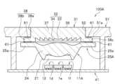
第1実施形態に係る光源装置100は、図1、図3に示すように、独立点灯可能な複数の発光装置1a~1iと、複数の発光装置1a~1iに対向して配置された第1レンズ11と、第1レンズ11に対向して配置された第2レンズ31と、を備え、第1レンズ11の発光装置1a~1iと対向する下面は、中央に配置され複数の発光装置1a~1iからの光が入射する入射部12と、入射部12の外側に配置され入射部12から入射する光を導光する導光部21と、を備え、第2レンズ31の第1レンズ11と対向する下面は、複数の環状の凸部34からなるフレネルレンズ面32を備えている。
また、光源装置100は、複数の発光装置1a~1iが載置される基板41と、第2レンズ31に開口部52を対向させて覆う筐体51と、を備えていてもよい。第1レンズ11は基板41に固定されていることが好ましい。さらに、光源装置100は、基板41に固定された第1レンズ11に、第2レンズ31が固定されていることが好ましい。以下、光源装置の各構成について説明する。First Embodiment
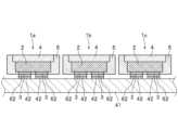
As shown in Figures 1 and 3, the
Furthermore, the
(発光装置)
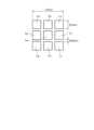
複数の発光装置は、独立点灯可能に発光装置1a~1iとして基板41に載置される。図3に示すように、複数の発光装置1a~1iは、全体として平面視で矩形状に配置されていることが好ましい。また、複数の発光装置1a~1iは、2行2列以上の正方格子状又は長方格子状に配置されていることがさらに好ましい。例えば、発光装置は、4個あるいは9個を縦横に等間隔で整列して全体として平面視で矩形となる領域を形成することが好ましい。
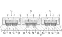
図4Aに示すように、発光装置1aは、上面を発光面として、上面と反対側の下面を実装面として基板41に載置される。発光装置1aは、発光素子2と、発光素子2の上面に設けられた透光性部材4と、透光性部材4の上面を除いて、発光素子2の側面と透光性部材4の側面とを覆う被覆部材5とを含む。なお、図4Bに示すように、透光性部材4の側面は被覆部材5から露出していても構わない。発光素子2の上面と反対側の下面には正負の電極3が設けられていることが好ましい。また、発光装置1aの平面視における形状は、例えば四角形が挙げられるが、円形、楕円形、三角形、六角形等の多角形であってもよい。なお、発光装置1b~1iにおいても、発光装置1aと同一の構成である。また、複数の発光装置を基板41に載置するのではなく、複数の発光素子2を備える1つの発光装置を基板41に載置してもよい。例えば、透光性部材4を備える複数の発光素子2が縦横に等間隔で整列して、1つの発光装置として被覆部材5により一体に成形されていてもよい。この場合も複数の発光素子2は独立点灯可能に基板41に載置される。(Light emitting device)
A plurality of light emitting devices are mounted on the
As shown in FIG. 4A, the
発光素子2は、III~V族化合物半導体、II~VI族化合物半導体等の種々の半導体からなることが好ましい。半導体としては、InXAlYGa1-X-YN(0≦X、0≦Y、X+Y≦1)等の窒化物系半導体を使用することが好ましく、InN、AlN、GaN、InGaN、AlGaN、InGaAlN等も使用できる。 The
透光性部材4は、平面視形状が略矩形状の板状の部材であり、発光素子2の上面を覆うように設けられている。透光性部材4は、透光性の樹脂材料や、セラミックス、ガラス等の無機物を用いて形成することができる。樹脂材料としては、シリコーン樹脂、シリコーン変性樹脂、エポキシ樹脂、フェノール樹脂などの熱硬化性樹脂を用いることができる。また、ポリカーボネート樹脂、アクリル樹脂、メチルペンテン樹脂、ポリノルボルネン樹脂などの熱可塑性樹脂を用いることができる。特に、耐光性、耐熱性に優れるシリコーン樹脂又はその変性樹脂が好適である。なお、ここでの透光性とは、発光素子2からの光の60%以上を透過し得る性質を指す。さらに、透光性部材4は、光拡散部材や発光素子2からの光の少なくとも一部を波長変換する蛍光体を含有してもよい。蛍光体を含有する透光性部材4としては、上述した樹脂材料、セラミックス、ガラス等に蛍光体を含有させたもの、蛍光体の焼結体等が挙げられる。また、透光性部材4は、樹脂、ガラス、セラミック等の成形体の下面に蛍光体や光拡散部材を含有する樹脂層を形成したものでもよい。
例えば、発光素子2として青色発光素子を用い、透光性部材4が黄色蛍光体を含むことにより白色光を発光する発光装置1が得られる。
透光性部材4に含まれる蛍光体としては、例えば、Y3Al5O12:Ceで表されるYAG蛍光体やシリケートなどの黄色蛍光体、あるいは、CaAlSiN3:Euで表されるCASN蛍光体やK2SiF6:Mnで表されるKSF蛍光体などの赤色蛍光体、を挙げることができる。
透光性部材4に含まれる光拡散部材としては、例えば、酸化チタン、チタン酸バリウム、酸化アルミニウム、酸化ケイ素などを用いることができる。 The light-transmitting
For example, by using a blue light-emitting element as the light-emitting
Examplesof the phosphor contained in the light-transmitting
The light diffusing material contained in the light-transmitting
被覆部材5は、発光素子2及び透光性部材4の側面を被覆する部材であり、発光素子2及び透光性部材4の側面を直接的に又は間接的に被覆する。透光性部材4の上面は被覆部材5から露出し、発光装置1の発光面(つまり主たる光取出し面)を構成する。被覆部材5は、光取出し効率を向上させるために、光反射率の高い部材で構成されることが好ましい。被覆部材5は、例えば、白色顔料等の光反射性物質を含有する樹脂材料を用いることができる。光反射性物質としては、酸化チタン、酸化亜鉛、酸化マグネシウム、炭酸マグネシウム、水酸化マグネシウム、炭酸カルシウム、水酸化カルシウム、珪酸カルシウム、珪酸マグネシウム、チタン酸バリウム、硫酸バリウム、水酸化アルミニウム、酸化アルミニウム、酸化ジルコニウム、酸化ケイ素等が挙げられ、これらのうちの1種を単独で、又はこれらのうちの2種以上を組み合わせて使用することが好ましい。また、樹脂材料としては、エポキシ樹脂、シリコーン樹脂、シリコーン変性樹脂、フェノール樹脂などの熱硬化性樹脂を主成分とする樹脂材料を母材とすることが好ましい。
なお、被覆部材5は、必要に応じて可視光に対して透光性を有する部材で構成することとしてもよい。 The covering
Note that the covering
(第1レンズ)
第1レンズ11は、発光装置1a~1iの発光面に対向して配置される。第1レンズ11は、複数の発光装置1a~1iからの光を集光し、第2レンズ31側に出射するものである。第1レンズ11としては、例えばコリメータレンズが挙げられる。第1レンズ11は、ポリカーボネート樹脂、アクリル樹脂、シリコーン樹脂、エポキシ樹脂等の透明樹脂で形成されることが好ましい。なお、第1レンズ11の形状は、平面視で円形や楕円形であることが好ましく、四角形や六角形等の多角形であってもよい。
第1レンズ11は、複数の発光装置1a~1iと対向する下面側に、中央に配置され発光装置1a~1iからの光が入射する入射部12と、入射部12の外側に同心円状に配置され入射部12から入射する光を導光する導光部21を備える。また、光源装置100を携帯電話機のフラッシュ光源として利用した際、一般的なカメラの撮影範囲が矩形状であることを考慮して、第1レンズ11は、その下面が平面視で4回回転対称形状であることが好ましい。また、第1レンズ11の下面は、平面視で2回回転対称形状であってもよい。(First lens)
The
入射部12は、第1レンズ11の下面に形成され、平面視で複数の発光装置1a~1iを内包する大きさで形成された凹部である。入射部12は、凹部の底面の形状が平面視で四角形が好ましく、円形、楕円形、三角形、四角形、六角形等であってもよい。また、凹部の底面は、ここではフレネルレンズ面に形成されていることが好ましい。つまり、入射部12は、中央に配置され発光装置1a~1i側に凸の下面凸部14と、下面凸部14の周囲に同心円状に配置され発光装置1a~1i側に凸状の角部16を備えていることが好ましい。さらに、角部16は、下面凸部14の周囲に同心円状に連続して又は断続して配置されることが好ましい。角部16は、ここでは、一周の同心円形状に形成されているが複数周となるように形成してもよい。角部16を備えることによって、下面凸部14の半径を小さくできるため、発光装置1a~1iからの光をより取り入れることができ、集光性が向上する。なお、凹部の内側面22は、平坦面であることが好ましいが、湾曲面であってもよい。The
導光部21は、第1レンズ11の下面側において、入射部12の外側に配置される。導光部21は入射部12から入射した光を反射する傾斜面23を有する。導光部21は、入射部12の周囲に同心円形状に連続して又は断続して環状に形成されていることが好ましい。これにより、発光装置1a~1iから出射される光のうち、出射角が大きく所望の照射範囲外に向かって出射される光を導光部21により集光することが可能となり、光取り出し効率を向上することができる。傾斜面23の光軸に対する傾斜角度は、発光装置1a~1iからの光を集光入射でき、反射できる角度に適宜設定される。The
第1レンズ11の上面は、中央に配置され第2レンズ31側に凸の上面凸部17と、上面凸部17の周囲に配置され、上面凸部17に連続する上面凹部18を介して配置される平坦部19とを有していることが好ましい。そして、上面凹部18は、上面凸部17の周囲に同心円状に凹環面状に形成されることが好ましい。また、上面凸部17は、平面視で下面凸部14よりも大きく形成されていることが好ましい。第1レンズ11が上面凸部17を有することによって、入射部12の下面凸部14及び/又は角部16から入射された光を第2レンズ側に取り出しやすくすることができる。また、第1レンズ11が上面凹部18を有することによって、傾斜面23で反射された光を第2レンズ側に取り出しやすくすることができる。さらに上面凹部18を有することで、傾斜面23の光軸に対する傾斜角度をより小さくすることができる。これにより、第1レンズ11のレンズ径を小さくすることができ、それに伴い第2レンズ31のレンズ径も小さくすることができる。さらに、それに伴い、筐体51の開口部52の径を小さくすることができる。これにより、開口部52の内部が視認されにくくなり、外観の見映えを向上させることができる。 The upper surface of the
なお、第1レンズ11は、図5に示すように、入射部12と導光部21とを有する第1本体部24と、第1本体部24の外縁から側方に延びる第1側縁部25とを備える。第1側縁部25は、第1上部領域25aと、第1上部領域25aから基板41側に延びる第1脚領域25bとを備えることが好ましい。第1側縁部25は、第1本体部24の外縁から側方に延在して第1本体部24を囲むように環状に形成されている。第1上部領域25aは、上部が平坦に形成されており、第1本体部24の上面凸部17の上端と同じ高さになるように形成されている。第1脚領域25bは、一例として第1上部領域25aの側方に連続して筒形状に形成されている。これにより、第1レンズ11は、第1側縁部25の第1脚領域25bの下面と基板41の上面とが接着部材61を介して固定することができると共に、第1側縁部25の第1上部領域25aの上面と第2レンズ31の下面とが接着部材61を介して固定することができる。ここで、接着部材61は、接着テープ等の公知の接着材を使用することができる。第1レンズ11は、第1本体部24及び第1側縁部25とが、一例として、同じ部材から加工して一体に形成されている。なお、第1本体部24及び第1側縁部25とは異なる材料から形成されていてもよく、例えば、第1本体部24は、光を透過する樹脂あるいはガラス材で形成され、第1側縁部25をアルミニウム合金等の金属で形成することとしても構わない。5, the
(第2レンズ)
第2レンズ31は、第1レンズ11に対向して配置され、第1レンズ11から出射された光を屈折させて所望の照射範囲内に出射するものである。第2レンズ31は、第1レンズ11と同様に、ポリカーボネート樹脂、アクリル樹脂、シリコーン樹脂、エポキシ樹脂等の透光性樹脂で形成されることが好ましい。なお、第2レンズ31の外形形状は、平面視で円形や楕円形であることが好ましく、四角形や六角形等の多角形であってもよい。
第2レンズ31は、フレネルレンズのような凸レンズ又は凹レンズであることが好ましい。第2レンズ31は、第1レンズ11と対向する下面には複数の環状の凸部34からなるフレネルレンズ面32を備える。フレネルレンズ面32は、第1レンズ11側に凸の中央凸部33と、中央凸部33の外側に同心円状に配置され第1レンズ11側に凸状となる複数の環状の凸部34と、を備える。複数の環状の凸部34は、平面視で中央凸部33に対して同心状に配置され、中央凸部33の形状に沿って環状となる形状に形成されることが好ましい。つまり、中央凸部33が平面視で円形であれば、凸部34は平面視が円環状に形成され、中央凸部33が平面視で矩形であれば、凸部34は平面視が矩形環状に形成される。フレネルレンズ面32は、平面視で第1レンズ11の入射部12及び導光部21を内包する大きさに形成されていることが好ましい。(Second lens)
The
The
なお、第2レンズ31は、図1、図6に示すように、第1レンズ側にフレネルレンズ面32を有すると共に、フレネルレンズ面32の反対側に筐体51の開口部52に対向する平坦面36を有する第2本体部37と、第2本体部37の外縁から側方に延びる第2側縁部38とを備えることが好ましい。なお、第2側縁部38は、第2本体部37の外縁から第1レンズ11側に延びる第2脚領域38aと、第2脚領域38aの下端に連続して側方に延びる第2取付領域38bとを備えることが好ましい。平坦面36は、平面視でフレネルレンズ面32と同等以上の大きさで形成され、筐体51の開口部52に第2本体部37が挿入された際には、筐体51の上面と同じ高さになるように形成されている。また、第2レンズ31は、平坦面36の表面に、シボ加工や微細な凹凸が施されていてもよい。As shown in Figs. 1 and 6, the
第2側縁部38は、第2本体部37の外縁から側方に延在させて環状に形成され、上面は平坦面36と同一面となるように形成されている。第2脚領域38aは、下端面がフレネルレンズ面32の下面よりも下方に位置するように形成されている。第2取付領域38bは、第2脚領域38aの下部側面から側方に延在させて環状に形成されている。第2取付領域38bは、下端が平坦に形成され、第2脚領域38aの下端と同一平面となるように形成されている。そして、第2取付領域38bは、第1レンズ11の第1上部領域25aに対面するように配置されていることが好ましい。これにより、第1側縁部25の上面と前記第2側縁部38の下面とを接着部材61を介して固定することができる。なお、第2レンズ31では、第1レンズ11の第1上部領域25aよりも中心側に第2脚領域38aが形成されている。つまり、図2に示すように、平面視において、第2レンズ31は第1レンズ11を内包するように固定されている。The
第2レンズ31は、第2脚領域38aの下面がフレネルレンズ面32よりも下方に位置することによって、第1レンズ11の第1本体部24と第2レンズ31の第2本体部37とを離間して配置することができる。それにより、第1レンズ11と第2レンズ31の干渉を抑制することができる。
また、第2レンズ31では、筐体51の開口部52に第2本体部37の平坦面36が露出するように挿入されると共に、開口部52の内周面に第2脚領域38aの外周面が当接するように設置されることが好ましい。また、光源装置100では、第2レンズ31の第2側縁部38の下面と、第1レンズ11の第1側縁部25の上面とが接着部材61を介して固定されていることが好ましい。 In the
Further, in the
(基板)
基板41は、複数の発光装置1a~1iが載置されるもので、表面及び/又は内部に配置された配線42を備えて構成されていることが好ましい。基板41では、配線42と発光装置1a~1iの正負の電極3とを導電性接着部材62を介して接続することによって、基板41と発光装置1a~1iとを電気的に接続する。なお、基板41の配線42は、発光装置1a~1iの電極3の構成、大きさに応じて構成、大きさ等が設定される。(substrate)
The
基板41は、絶縁性材料を用いることが好ましく、かつ、発光装置1a~1iから出射される光や外光などを透過しにくい材料を用いることが好ましく、ある程度の強度を有する材料を用いることが好ましい。具体的には、基板41は、アルミナ、窒化アルミニウム、ムライト等のセラミックス、フェノール樹脂、エポキシ樹脂、ポリイミド樹脂、BTレジン(bismaleimide triazine resin)、ポリフタルアミド等の樹脂で構成することができる。 For the
配線42は、銅、鉄、ニッケル、タングステン、クロム、アルミニウム、銀、金、チタン、パラジウム、ロジウム又はこれらの合金等で構成することができる。また、配線42の表層には、導電性接着部材62の濡れ性及び/又は光反射性等の観点から、銀、白金、アルミニウム、ロジウム、金又はこれらの合金等の層が設けられていてもよい。 The
(筐体)
筐体51は、第2レンズ31に開口部52を対向させて覆うもので、例えば、光源装置100をフラッシュ光源として用いる携帯電話機の筐体の一部であってもよい。開口部52は、第2レンズ31の第2本体部37の平坦面36が露出するように、第2本体部37よりも大きく形成されていることが好ましい。また、筐体51は、基板41と固定されるための脚部53を備えていてもよい。さらに、筐体51は、遮光部材からなることが好ましく、光源装置100から出射される光の配光方向を制限できるように、例えば、光反射部材、光吸収部材等のフィラーを含有させた樹脂材料等により構成することが好ましい。開口部52の形状は、平面視で円形、楕円形、三角形、四角形、六角形等が挙げられる。(Case)
The
光源装置100では、第1レンズ11と第2レンズ31とを組み合わせることによって、複数の発光装置1a~1iの点灯配置に対応した所望の方向に光を照射できる。
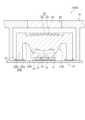
例えば、図7Aに示すように、平面視で矩形形状に配置された複数の発光装置のうち、矩形の中心部に配置された1つの発光装置1eが点灯した際には、図7Bに示すように、主に第1レンズ11の下面凸部14を通過する光が、上面凸部17及び第2レンズ31で屈折されて、所定の照射範囲の矩形中心部に照射される。なお、図7Cに、矩形中心部に配置された発光素子点灯時の照度分布を示す。また、図8Aに示すように、複数の発光装置のうち、矩形の角部を除く端部に配置された1つの発光装置1bが点灯した際には、図8Bに示すように、主に第1レンズ11の下面凸部14及び導光部21を通過する光が、上面凸部17、上面凹部18及び第2レンズ31で屈折されて、所定の照射範囲の角部を除く矩形端部に照射される。なお、図8Cに、角部を除く矩形端部に配置された発光素子点灯時の照度分布を示す。さらに、図9Aに示すように、複数の発光装置のうち、矩形の角部に配置された1つの発光装置1cが点灯した際には、図9Bに示すように、主に第1レンズ11の下面凸部14及び導光部21を通過する光が、上面凸部17、上面凹部18及び第2レンズ31で屈折されて、所定の照射範囲の矩形角部に照射される。なお、図9Cに、矩形角部に配置された発光素子点灯時の照度分布を示す。
さらに、複数の発光装置1a~1iを全灯点灯させる際には、各発光装置の出力を個別に調整することで、限られた電力内で、任意の照度分布を作り出すことが可能となる。 In the
For example, as shown in FIG. 7A, when one light-emitting
Furthermore, when all of the
また、光源装置100では、出射面(トップ面)側に配置される第2レンズ31がフレネルレンズ面32を備えることで、光源装置100の内部の発光装置1a~1iを外部から視認しにくくすることができ、外観の見映えを向上させることができる。 Furthermore, in the
光源装置100では、前記したように第1レンズ11を基板41に固定し、基板41に固定された第1レンズ11に、筐体51の開口部52に第2本体部37を挿入した第2レンズ31を固定する。そのため、光源装置100を携帯電話機等のフラッシュ光源として利用した際、光源装置100の装置厚みH1を薄くすることが可能となる。その結果、携帯電話機の薄型化に貢献できる。In the
<第2実施形態>
図10は、第2実施形態に係る光源装置の構成を模式的に示す断面図である。
第2実施形態に係る光源装置100Aは、第2レンズ31が筐体51に固定されていること、第1レンズ11Aの第1側縁部25が実質的に第1上部領域25aのみからなること以外は、第1実施形態に係る光源装置100と同一の構成を備える。以下、光源装置100と異なる部分を中心に説明し、同一の構成については適宜省略する。<Second embodiment>
FIG. 10 is a cross-sectional view schematically showing the configuration of a light source device according to the second embodiment.
In the
光源装置100Aは、複数の発光装置1a~1iが載置される基板41と、第2レンズ31に開口部52を対向させて覆う筐体51と、第2レンズ31に対向して配置される第1レンズ11Aとを備えている。そして、第1レンズ11Aは、入射部12と導光部21とを有する第1本体部24と、第1本体部24の外縁から側方に延びる第1側縁部25Aとを備えている。また、第1側縁部25Aは、第1上部領域25aを有している。そして、第1レンズ11Aは、第1上部領域25aに接着部材61を介して第2レンズ31の第2取付領域38bに接続されており、基板41と離間して配置されている。そのため、第1レンズ11A及び第2レンズ31を接合した状態で筐体51に取り付けることができるので、製造作業効率を向上させることができる。また、第1レンズ11A及び第2レンズ31は、光軸を筐体51に取り付ける前に整合させることができ、位置関係の調整作業が容易になり、第1レンズ11Aの光軸と第2レンズ31の光軸とのズレを抑制することができる。さらに、レンズ同士のズレにより生じる外観の見た目の悪化を抑制することができる。 The
<第3実施形態>
図11は、第3実施形態に係る光源装置の構成を模式的に示す断面図である。
第3実施形態に係る光源装置100Bは、第1レンズ11が基板41に固定され、第2レンズ31が筐体51に固定されていること、第1レンズ11と第2レンズ31とが互いに固定されていないこと以外は、第1実施形態に係る光源装置100と同一の構成を備える。<Third embodiment>
FIG. 11 is a cross-sectional view schematically showing the configuration of a light source device according to the third embodiment.
In the
光源装置100Bは、第2レンズ31の第2取付領域38bの上面に接着部材61を介して筐体下面51aに第2レンズ31を取り付けると共に、第1レンズ11の第1脚領域25bの下面に接着部材61を介して第1レンズ11を基板41に取り付けている。このように光源装置100Bでは、第1レンズ11を基板41に取り付け、第2レンズ31を筐体51に取り付けることで、製造作業の手順において融通性を高めることができる。In the
<第4実施形態>
図12は、第4実施形態に係る光源装置の構成を模式的に示す断面図である。
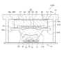
第4実施形態に係る光源装置100Cは、筐体51の開口部52に透明部材54が組み込まれていること、第2レンズ31Cの第2側縁部38Cが実質的に第2脚領域38aのみからなること以外は、第1実施形態に係る光源装置100と同一の構成を備える。なお、透明部材54は、ガラス、透明樹脂等から構成されることが好ましい。<Fourth embodiment>
FIG. 12 is a cross-sectional view schematically showing the configuration of a light source device according to the fourth embodiment.
The
光源装置100Cは、複数の発光装置1a~1iが載置される基板41と、開口部52を有する筐体51と、第1レンズ11と、第2レンズ31Cと、を備え、開口部52に透明部材54が組み込まれている。そして、光源装置100Cは、透明部材54の中心に第1レンズ11の中心及び第2レンズ31の中心が配置されている。なお、第2レンズ31Cは、フレネルレンズ面32を有すると共に、フレネルレンズ面32の反対側に平坦面36を有する第2本体部37と、第2本体部37の外縁から側方に延びる第2側縁部38Cとを備えている。
そして、第2側縁部38Cとして、第2本体部37の外縁から側方に延びる第2脚領域38aを備えている。第2脚領域38aは、下端面がフレネルレンズ面32よりも下方に位置するように形成されている。また、第2脚領域38aは、第2本体部37の外縁に筒状に形成されている。第2脚領域38aは、その下端面を第1レンズ11の第1上部領域25aに対面するように形成している。
第2レンズ31Cは、第2脚領域38aの上面に接着部材61を介して筐体51の筐体下面51aに接続されると共に、第2脚領域38aの下端面に接着部材61を介して第1レンズ11の第1上部領域25aに接続される。また、第1レンズ11は、基板41の上面と第1脚領域25bの下面とが接着部材61を介して固定される。 The
A
The
光源装置100Cでは、保護部材として透明部材54を備えているので、第2レンズ31の平坦面36が、筐体51外部に露出することがなく劣化が抑制される。また、光源装置100Cを携帯電話機のフラッシュ光源として利用した際、発光装置1a~1iとの間に透明部材54、第2レンズ31及び第1レンズ11を介することになり、外部から、光源装置100Cの内部の発光装置1a~1iを視認しにくくすることができ、外観の見映えを向上させることができる。さらに、光源装置100Cは、接着部材61により接着される箇所が多いため、衝撃による位置ずれ等が防止される。Since the
<第5実施形態>
図13は、第5実施形態に係る光源装置100Dの構成を模式的に示す断面図である。
第5実施形態に係る光源装置100Dは、第2レンズ31Cが筐体51に固定されていること、第1レンズ11Aの第1側縁部25Aが実質的に第1上部領域25aのみからなること以外は、第4実施形態に係る光源装置100Cと同一の構成を備える。<Fifth embodiment>
FIG. 13 is a cross-sectional view schematically showing the configuration of a
In the
光源装置100Dは、複数の発光装置1a~1iが載置される基板41と、第2レンズ31Cに開口部52が対向するように覆う筐体51と、第2レンズ31Cに対向して配置される第1レンズ11Aと、を備え、開口部52に透明部材54が組み込まれている。そして、第1レンズ11Aが、入射部12と導光部21とを有する第1本体部24と、第1本体部24の外縁から側方に延びる第1側縁部25Aとを備えている。また、第1側縁部25Aは、実質的に第1上部領域25aのみから形成されている。さらに、第2レンズ31Cは、フレネルレンズ面32を有すると共に、フレネルレンズ面32の反対側に平坦面36を有する第2本体部37と、第2本体部37の外縁から側方に延びる第2側縁部38Cとを備えている。そして、第2側縁部38Cは、第2本体部37の外縁から側方に延びる第2脚領域38aを備えている。 The
さらに、第2レンズ31Cは、透明部材54に第2本体部37の平坦面36が対向するように、開口部52の周縁の筐体下面51aと第2脚領域38aの上面とが接着部材61を介して固定されている。また、第2レンズ31Cは、第2側縁部38Cの第2脚領域38aの下面と、第1レンズ11Aの第1側縁部25Aの第1上部領域25aの上面とが接着部材61を介して固定されている。なお、第1レンズ11A及び第2レンズ31Cは、透明部材54の中心と、第1レンズ11Aの光軸中心と第2レンズ31Cの光軸中心とが揃うように配置されることが好ましい。
光源装置100Dでは、第1レンズ11A及び第2レンズ31Cを接着部材61により接着した状態で筐体51の筐体下面51aに接着部材61を介して透明部材54に対面して筐体51に設置でき、作業効率がよい。
さらに、開口部52の位置に合わせて、接着された第1レンズ11A及び第2レンズ31Cの位置関係の調整が容易にできることで、開口部52とのズレを抑制することができ、ズレによる外観の見た目の悪化を抑制することができる。 Further, in the
In the
Furthermore, since the positional relationship between the bonded
<第6実施形態>
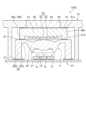
図14は、第6実施形態に係る光源装置100Eの構成を模式的に示す断面図である。
第6実施形態に係る光源装置100Eは、第1レンズ11が基板41に固定され、第2レンズ31Eが筐体51に固定されていること、第2レンズ31の第2側縁部38Eが実質的に第2脚領域38aのみからなること、接着部材61による接着箇所が異なる以外は、第4実施形態に係る光源装置100Cと同一の構成を備える。<Sixth embodiment>
FIG. 14 is a cross-sectional view schematically showing the configuration of a
In the
光源装置100Eは、複数の発光装置1a~1iが載置される基板41と、第2レンズ31Eに開口部52を対向させて覆う筐体51と、第2レンズ31Eに対向して配置される第1レンズ11とを備え、開口部52に透明部材54が組み込まれている。そして、第1レンズ11が、入射部12と導光部21とを有する第1本体部24と、第1本体部24の外縁から側方に延びる第1側縁部25とを備え、第1側縁部25が、第1本体部24の外縁から側方に延びる第1上部領域25aと、第1上部領域25aから基板41側に延びる第1脚領域25bとを備えている。The
また、第2レンズ31Eは、フレネルレンズ面32を有すると共に、フレネルレンズ面32の反対側に平坦面36を有する第2本体部37と、第2本体部37の外縁から側方に延びる第2側縁部38とを備えている。そして、第2レンズ31Eは、透明部材54に第2本体部37の平坦面36が対向するように配置されている。また、第2側縁部38Eにおいて、第2脚領域38aの下面はフレネルレンズ面32より上方に位置する。第2脚領域38aは、第2本体部37の外縁から側方に延伸して所定の厚みを有するように形成されている。第2レンズ31Eは、開口部52の周縁の筐体下面51aと第2脚領域38aの上面とが接着部材61を介して固定される。なお、フレネルレンズ面32を保護するために、第2脚領域38aの下面はフレネルレンズ面32より下方に位置していてもよい。 The
また、第1レンズ11は、基板41の上面と第1脚領域25bの下面とが接着部材61を介して固定される。なお、第2レンズ31Eは、第1レンズ11と所定の間隔を隔てて配置できるように、筐体下面51aに接着部材61により接続させている。また、第1レンズ11及び第2レンズ31Eは、それぞれの光軸中心が、透明部材54の中心に揃うように配置されることが好ましい。
光源装置100Eでは、第1レンズ11を基板41側に取り付け、第2レンズ31Eを筐体51側に取り付けているため、第1レンズ11と第2レンズ31Eとを個別に取り換えることが容易となる。光源装置100Eでは、第2レンズ31Eを筐体51側に取り付けているため、第2レンズ31Eと筐体51との位置合わせが容易になり、位置ずれが抑制されて外観の見映えが向上する。 The
In the
<第7実施形態>
図15は、第7実施形態に係る光源装置100Fの構成を模式的に示す断面図である。
第7実施形態に係る光源装置100Fは、基板41に固定された第1レンズ11に固定された第2レンズ31Cが、筐体51に固定されていないこと以外は、第4実施形態に係る光源装置100Cと同一の構成を備える。
光源装置100Fでは、第1レンズ11に固定された第2レンズ31Cが筐体51に固定されていないため、第1レンズ11と第2レンズ31Cとを同時に取り換えることができる。また、光源装置100Fでは、第1レンズ11を基板41に固定した後、基板41に固定された第1レンズ11に第2レンズ31Cを固定することができる。つまり、発光装置1の位置に合わせて第1レンズ11を配置した後に、第2レンズ31Cを配置することができる。これにより、発光装置1の光軸とレンズの中心とのズレによる、光学特性の悪化や外観の見た目の悪化が抑えられる。<Seventh embodiment>
FIG. 15 is a cross-sectional view schematically showing the configuration of a
The
In the
<第8実施形態>
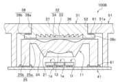
図16は、第8実施形態に係る光源装置100Gの構成を模式的に示す断面図である。
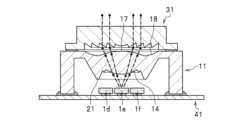
第8実施形態に係る光源装置100Gは、第2レンズ31Cがなく、基板41に固定された第1レンズ11Bの上面がフレネルレンズ面32で構成されていること以外は、第7実施形態に係る光源装置100Fと同一の構成を備える。また、光源装置100Gでは、フレネルレンズ面32は、出射面となる筐体51側に凸状となる中央凸部33と、中央凸部33の形状に沿って同心円形状に配置され筐体51側に凸状となる複数の環状の凸部34と、を備える。さらに、光源装置100Gでは、第1レンズ11Bがフレネルレンズ面32を備えるため、光源装置100Fに比べて光源装置全体の厚みを薄くすることができる。そのため、光源装置100Gを携帯電話機等のフラッシュ光源として利用した際、光源装置100Gの装置厚みをより薄くすることが可能となるため、携帯電話機の薄型化に貢献できる。Eighth Embodiment
FIG. 16 is a cross-sectional view that illustrates a schematic configuration of a
The
光源装置100Gでは、第1レンズ11Bが、入射部12と導光部21とからなる下面と、フレネルレンズ面32からなる上面とを、を有する。そのため、光源装置100Gでは、発光装置1からの光を無駄なく第1レンズ11Bの下面から取り込めることによる光ロスの軽減が図れると共に、筐体51の開口部52のサイズを小さくしたまま、発光効率の向上や広角配光への制御が可能となる。また、光源装置100Gでは、発光装置1の光軸と第1レンズ11Bの中心とのズレによる光学特性の悪化や、外観の見た目の悪化が抑えられる。 In the
<第9実施形態>
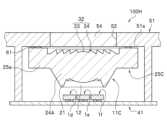
図17Aは、第9実施形態に係る光源装置100Hの構成を模式的に示す断面図である。図17Bは、第9実施形態に係る光源装置100Hの第1レンズ11Cの発光装置側から見た平面図である。
第9実施形態に係る光源装置100Hは、第2レンズ31Cがなく、筐体51に固定された第1レンズ11Cの上面がフレネルレンズ面32で構成されていること、第1レンズ11Cの下面が平面視で4回回転対称よりもより複雑な2回回転対称形状であること以外は、第5実施形態に係る光源装置100Dと同一の構成を備える。
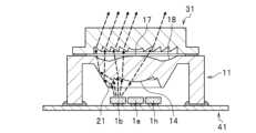
また、光源装置100Hでは、フレネルレンズ面32は、出射面となる筐体51側に凸状となる中央凸部33と、中央凸部33の形状に沿って同心円形状に配置され筐体51側に凸状となる複数の環状の凸部34と、を備える。さらに、光源装置100Hでは、第1レンズ11Cがフレネルレンズ面32を備えるため、光源装置100Dに比べて光源装置全体の厚みを薄くすることができる。そのため、光源装置100Hを携帯電話機等のフラッシュ光源として利用した際、光源装置100Hの装置厚みをより薄くすることが可能となるため、携帯電話機の薄型化に貢献できる。
さらに、本実施形態では、図17Bに示すように、第1レンズ11Cの下面が平面視で2回回転対称形状としている。本実施形態の光源装置をカメラのフラッシュ光源として利用する際には、カメラの撮影画角が16:9、4:3等の長方形形状であることを考慮して、第1レンズ11Cの下面は平面視で2回回転対称形状とすることが好ましい。なお、第1レンズ11Cの下面は、平面視で4回回転対称形状であってもよい。<Ninth embodiment>
FIG. 17A is a cross-sectional view schematically showing the configuration of a
The
Further, in the
Furthermore, in this embodiment, as shown in FIG. 17B, the lower surface of the
光源装置100Hでは、開口部52の位置に合わせて、第1レンズ11Cの位置関係の調整が容易にできることで、開口部52とのズレを抑制することができ、外観の見た目の悪化を抑制することができる。 In the
以下、実施例の光源装置のモデルを用いて行った光学シミュレーションについて説明する。なお、光源装置は、以下の実施例に限定されるものではない。
図18Aは、実施例の光源装置における発光装置の点灯状態を示し、9個全ての発光装置1a~1iが点灯していることを示す模式図である。図18Bは、図18Aの光源装置における照度分布を示す模式図である。図19Aは、実施例の光源装置における発光装置の点灯状態を示し、9個の発光装置1a~1iのうち、8個の発光装置1a~1d、1f~1iが点灯していることを示す模式図である。図19Bは、図19Aの光源装置における照度分布を示す模式図である。図20Aは、実施例の光源装置における発光装置の点灯状態を示し、9個の発光装置1a~1iのうち、5個の発光装置1a~1c、1f、1iが点灯していることを示す模式図である。図20Bは、図20Aの光源装置における照度分布を示す図である。なお、図18A、図19A及び図20Aにおいて、単純に白黒のみで発光装置の点灯状態及び消灯状態を示している。 Optical simulation performed using the model of the light source device of the example will be described below. Note that the light source device is not limited to the following embodiments.
FIG. 18A is a schematic diagram showing the lighting state of the light emitting devices in the light source device of the example, and showing that all nine light emitting
図1に示す実施形態の光源装置100の構成に基づき、シミュレーションにより、発光装置1a~1iからの光が第1レンズ11及び第2レンズ31を介してどのように照射されるかを求めた。
実施例の光源装置100のモデルにおいて、各発光装置の発光面は一辺が0.5mmの正方形であるとした。平面視で矩形形状に配置された9個の発光装置1a~1iの発光面の中心となる発光装置1eの発光面の中心を原点とし、以下の座標に一致するように、発光装置1a~1iを配置した。なお、以下の座標は、mmである。
発光装置1aの発光面の中心:(-0.55,0.55)
発光装置1bの発光面の中心:(0,0.55)
発光装置1cの発光面の中心:(0.55,0.55)
発光装置1dの発光面の中心:(-0.55,0)
発光装置1eの発光面の中心:原点(0,0)
発光装置1fの発光面の中心:(0.55,0)
発光装置1gの発光面の中心:(-0.55,-0.55)
発光装置1hの発光面の中心:(0,-0.55)
発光装置1iの発光面の中心:(0.55,-0.55) Based on the configuration of the
In the model of the
Center of light emitting surface of light emitting
Center of light emitting surface of light emitting
Center of light emitting surface of light emitting
Center of light emitting surface of light emitting
Center of light emitting surface of light emitting
Center of light emitting surface of light emitting
Center of light emitting surface of 1g light emitting device: (-0.55, -0.55)
Center of light emitting surface of light emitting
Center of light emitting surface of light emitting
実施例の光源装置100において、第1レンズ11は、図1、図5に示すように、その下面において、平面視で下面中央に配置された一辺が0.57mmの正方形状をなす下面凸部14と下面凸部14の外周に連続して幅0.19mmで正方環状に配置された角部16とからなる入射部12と、角部16の外周に連続して幅0.49mmで正方環状に配置された導光部21と、を備える。また、第1レンズ11は、その上面において、平面視で上面中央に配置された一辺が0.71mmの正方形状をなす上面凸部17と、上面凸部17に連続して上面凹部18を介して幅1.3mmで正方環状に配置された平坦部19と、を備える。 In the
実施例の光源装置100において、第2レンズ31は、図6に示すように、その下面において、フレネルレンズ面32を有する。第2レンズ31は、平面視でフレネルレンズ面32の中心に配置された半径が0.45mmの円形状をなす中央凸部33と、フレネルレンズ面の中心から最も離れた半径1.5mmの位置に頂点を有して中央凸部33と同心円状に配置された凸部34と、その凸部34と中央凸部33との間に中央凸部33と同心円状に等間隔に配置された複数の凸部34と、を備える。また、第2レンズ31の上面には、平面視で半径1.77mmの円形状をなす平坦面36を備える。なお、実施例の光源装置100においては4つの凸部34を備えることとした。In the
実施例の光源装置100のモデルを用いて、全部又は一部の発光装置1a~1iを点灯させた際の照度分布を、以下の測定条件でシミュレ-ションにより求めた。
(測定条件)
評価用受光器のサイズ:280×370mm
発光装置と評価用受光器との距離:300mm
評価用受光器の画角:75度
発光装置トップ面と第1レンズとの距離:0.1mm Using the model of the
(Measurement condition)
Size of evaluation receiver: 280 x 370 mm
Distance between light emitting device and evaluation receiver: 300mm
Angle of view of evaluation receiver: 75 degrees Distance between top surface of light emitting device and first lens: 0.1 mm
図18A~図20Bに示すように、実施形態の光源装置100により、点灯箇所に対応した照度分布が得られることが確認された。また、実施形態の光源装置100により、所望の照射範囲に光を照射したときに、その所望の照射範囲内における照度と照度範囲外における照度との照度差を大きくできることが確認された。なお、光源装置100では、第1レンズ11及び第2レンズ31を介して光が照射されるため、レンズに応じた屈折方法に光が照射されることになる。As shown in Figures 18A to 20B, it was confirmed that the
図18Aに示すような9個の発光装置1a~1iを全灯点灯させる際には、各発光装置の出力を調整することで、限られた電力内で、任意の照度分布を作り出せることも確認された。例えば、中央がより明るいフラッシュが必要の場合は、矩形の中心部に配置された1つの発光装置1eにより多くの電力を投入することで、中心照度が高くより明るいフラッシュを得ることができた。また、広範囲を均一に照射したい場合は、各光源の投入電力のバランスを取ることで、均一な照度分布を作り出すことも可能であった。なお、通常、発光装置1a~1iのすべてを同じ投入電力(同じ明るさ)にしてしまうと、発光装置が密集する矩形中心部近傍が明るく、矩形角部及び矩形端部が暗い照度分布となってしまうため、矩形中心部に配置された発光装置1eの投入電力を小さく、矩形角部及び矩形端部に配置された発光装置1a~1c、1d、1f、1g~1iの投入電力を大きくすることで、より均一な照度分布が得られることが確認できた。 It was also confirmed that when all nine light emitting
以上説明した各構成は、様々な変更をすることができる。例えば、第1レンズにおいてフレネルレンズ面の角部16の数を増やすことや、あるいは、フレネルレンズ面の曲率を適宜変えることとしてもよい。また、第1レンズにおいて、TIRレンズ面に形成された場合には、角部16の立ち上げ角度や傾斜面の角度を適宜変更してもよい。また、それぞれの第2レンズの平坦面を筐体の表面と同一平面としているが、当該平坦面に防護シートを張り、その防護シートを筐体と同一平面としてもよい。Various modifications can be made to each of the configurations described above. For example, the number of
1a、1b、1c、1d、1e、1f、1g、1h、1i 発光装置
2 発光素子
3 電極
4 透光性部材
5 被覆部材
11、11A、11B、11C 第1レンズ
12 入射部
14 下面凸部
16 角部
17 上面凸部
18 上面凹部
19 平坦部
21 導光部
22 内側面
23 傾斜面
24、24A 第1本体部
25、25A、25B、25C 第1側縁部
25a 第1上部領域
25b 第1脚領域
31、31C、31E 第2レンズ
32 フレネルレンズ面
33 中央凸部
34 凸部
36 平坦面
37 第2本体部
38、38C、38E 第2側縁部
38a 第2脚領域
38b 第2取付領域
41 基板
42 配線
51 筐体
51a 筐体下面
52 開口部
53 脚部
54 透明部材
61 接着部材
62 導電性接着部材
100、100A、100B、100C、100D、100E、100F、100G、100H 光源装置1a, 1b, 1c, 1d, 1e, 1f, 1g, 1h, 1i
Claims (12)
Translated fromJapanese前記発光装置に対向して配置される第1下面と、前記第1下面の反対側の第1上面と、を有する第1レンズと、
前記第1レンズに対向して配置される第2下面と、前記第2下面の反対側の第2上面と、を有する第2レンズと、を備え、
前記第1レンズの前記第1下面は前記発光装置側に凸の下面凸部を有し、前記第1レンズの前記第1上面は前記第2レンズ側に凸の上面凸部を有し、
前記第2レンズの前記第2下面は、同心円状に配置される複数の環状の凸部を備え、
前記第1レンズにおいて、前記上面凸部は、平面視で前記下面凸部よりも大きく、
前記第1下面は、前記下面凸部を底面とする凹部を有し、前記凹部の外側に、前記第1レンズの光軸に対して傾斜する傾斜面を備える、光源装置。 A light-emitting device comprising a plurality of light-emitting elements each having a light-transmitting member on its upper surface, and a covering member exposing the upper surface of the light-transmitting member and covering the side surfaces of the light-transmitting member and the light-emitting element;
a first lens having a first lower surface disposed to face the light emitting device; and a first upper surface opposite to the first lower surface;
a second lens having a second lower surface disposed opposite to the first lens, and a second upper surface opposite to the second lower surface,
The first lower surface of the first lens has a lower convex portion that is convex toward the light emitting device, and the first upper surface of the first lens has a convex upper surface that is convex toward the second lens,
The second lower surface of the second lens includes a plurality of annular convex portions arranged concentrically,
In the first lens, the upper surface convex portion islarger than the lower surface convex portion in plan view;
The first lower surface has a concave portion whose bottom surface is the convex portion of the lower surface, and the light source device includes an inclined surface inclined with respect to the optical axis of the first lens on the outside of the concave portion .
前記発光装置に対向して配置される第1下面と、前記第1下面の反対側の第1上面と、を有する第1レンズと、
前記第1レンズに対向して配置される第2下面と、前記第2下面の反対側の第2上面と、を有する第2レンズと、を備え、
前記第1レンズの前記第1下面は前記発光装置側に凸の下面凸部を有し、前記第1レンズの前記第1上面は前記第2レンズ側に凸の上面凸部を有し、
前記第2レンズの前記第2下面は、同心円状に配置される複数の環状の凸部を備え、
前記第1レンズにおいて、前記上面凸部は、平面視で前記下面凸部よりも大きく、
前記第1レンズは、前記第1上面において前記上面凸部の外縁から側方に延びる第1側縁部を有し、
前記第2レンズは、前記第2下面において前記複数の環状の凸部の外縁から側方に延びる第2側縁部を有し、
前記第1側縁部の上面と前記第2側縁部の下面とが接着部材を介して固定される、光源装置。 a light emitting device including: a plurality of light emitting elements each having a light transmissive member on an upper surface thereof; and a covering member exposing an upper surface of the light transmissive member and covering a side surface of the light transmissive member and the light emitting elements;
a first lens having a first lower surface disposed opposite the light emitting device and a first upper surface opposite the first lower surface;
a second lens having a second lower surface disposed opposite the first lens and a second upper surface opposite the second lower surface;
the first lower surface of the first lens has a lower surface convex portion that is convex toward the light emitting device, and the first upper surface of the first lens has an upper surface convex portion that is convex toward the second lens,
the second lower surface of the second lens includes a plurality of annular convex portions arranged concentrically;
In the first lens, the upper surface convex portion islarger than the lower surface convex portion in a plan view,
the first lens has a first side edge portion extending laterally from an outer edge of the upper surface convex portion on the first upper surface,
the second lens has a second side edge portion extending laterally from an outer edge of the plurality of annular convex portions on the second lower surface,
An upper surface of the first side edge portion and a lower surface of the second side edge portion are fixed together via an adhesive member .
前記第2レンズは、前記第2下面において前記複数の環状の凸部の外縁から側方に延びる第2側縁部を有し、
前記第1側縁部の上面と前記第2側縁部の下面とが接着部材を介して固定される、請求項1を引用する請求項1から請求項9のいずれか一項に記載の光源装置。 The first lens has a first side edge portion extending laterally from an outer edge of the upper surface convex portion on the first upper surface,
The second lens has a second side edge portion extending laterally from an outer edge of the plurality of annular convex portions on the second lower surface,
The light source according to any one ofclaims 1 to 9, referring to claim 1, wherein the upper surface of the first side edge and the lower surface of the second side edge are fixed via an adhesive member. Device.
前記第1レンズは前記基板に固定されている請求項1から請求項11のいずれか一項に記載の光源装置。 The light emitting device further includes a substrate on which the light emitting device is mounted.
The light source device accordingto claim 1 , wherein the firstlens is fixed to the substrate.
Priority Applications (1)
| Application Number | Priority Date | Filing Date | Title |
|---|---|---|---|
| JP2023019322AJP7460936B2 (en) | 2019-10-30 | 2023-02-10 | light source device |
Applications Claiming Priority (2)
| Application Number | Priority Date | Filing Date | Title |
|---|---|---|---|
| JP2019197985AJP7231831B2 (en) | 2019-10-30 | 2019-10-30 | Light source device |
| JP2023019322AJP7460936B2 (en) | 2019-10-30 | 2023-02-10 | light source device |
Related Parent Applications (1)
| Application Number | Title | Priority Date | Filing Date |
|---|---|---|---|
| JP2019197985ADivisionJP7231831B2 (en) | 2019-10-30 | 2019-10-30 | Light source device |
Publications (2)
| Publication Number | Publication Date |
|---|---|
| JP2023054077A JP2023054077A (en) | 2023-04-13 |
| JP7460936B2true JP7460936B2 (en) | 2024-04-03 |
Family
ID=75713364
Family Applications (2)
| Application Number | Title | Priority Date | Filing Date |
|---|---|---|---|
| JP2019197985AActiveJP7231831B2 (en) | 2019-10-30 | 2019-10-30 | Light source device |
| JP2023019322AActiveJP7460936B2 (en) | 2019-10-30 | 2023-02-10 | light source device |
Family Applications Before (1)
| Application Number | Title | Priority Date | Filing Date |
|---|---|---|---|
| JP2019197985AActiveJP7231831B2 (en) | 2019-10-30 | 2019-10-30 | Light source device |
Country Status (5)
| Country | Link |
|---|---|
| US (3) | US11867390B2 (en) |
| EP (1) | EP4053600A4 (en) |
| JP (2) | JP7231831B2 (en) |
| CN (1) | CN114641654B (en) |
| WO (1) | WO2021084919A1 (en) |
Families Citing this family (9)
| Publication number | Priority date | Publication date | Assignee | Title |
|---|---|---|---|---|
| JP7231831B2 (en) | 2019-10-30 | 2023-03-02 | 日亜化学工業株式会社 | Light source device |
| JP7148813B2 (en) | 2019-10-30 | 2022-10-06 | 日亜化学工業株式会社 | Light source device |
| JP7291086B2 (en)* | 2020-01-29 | 2023-06-14 | スタンレー電気株式会社 | lighting equipment |
| US11946637B2 (en) | 2021-04-05 | 2024-04-02 | Nichia Corporation | Light source device |
| CN117677794A (en)* | 2021-08-02 | 2024-03-08 | 莱迪尔公司 | Optical device for modifying light distribution |
| US12018832B2 (en)* | 2021-09-23 | 2024-06-25 | Apple Inc. | Light source module with adaptive illumination |
| WO2023145248A1 (en)* | 2022-01-27 | 2023-08-03 | 日亜化学工業株式会社 | Light emission module |
| US12206994B2 (en) | 2022-09-06 | 2025-01-21 | Apple Inc. | Image capture systems utilizing adjustable illumination |
| US20250093010A1 (en)* | 2023-09-20 | 2025-03-20 | Nichia Corporation | Light transmissive member, light source device, method of producing light transmissive member, and method of producing light source device |
Citations (4)
| Publication number | Priority date | Publication date | Assignee | Title |
|---|---|---|---|---|
| JP2012104256A (en) | 2010-11-08 | 2012-05-31 | Toshiba Lighting & Technology Corp | Lighting device |
| JP2017016995A (en) | 2015-07-02 | 2017-01-19 | 株式会社エンプラス | Light-emitting device, surface light source device and display device |
| JP2017103051A (en) | 2015-11-30 | 2017-06-08 | 岩崎電気株式会社 | lamp |
| JP2019160780A (en) | 2018-03-09 | 2019-09-19 | 日亜化学工業株式会社 | Light source device |
Family Cites Families (49)
| Publication number | Priority date | Publication date | Assignee | Title |
|---|---|---|---|---|
| JPS63106738A (en)* | 1986-10-24 | 1988-05-11 | Dainippon Printing Co Ltd | Lens plate for transmission screen |
| US5526190A (en) | 1994-09-29 | 1996-06-11 | Xerox Corporation | Optical element and device for providing uniform irradiance of a surface |
| EP1056971A1 (en) | 1998-12-17 | 2000-12-06 | Koninklijke Philips Electronics N.V. | Light engine |
| JP2002072037A (en) | 2000-09-01 | 2002-03-12 | Sony Corp | Optical system, method of manufacturing optical system and optical pickup |
| JP2004046053A (en) | 2002-05-21 | 2004-02-12 | Matsushita Electric Ind Co Ltd | Objective lens and optical head device |
| TWI249257B (en) | 2004-09-24 | 2006-02-11 | Epistar Corp | Illumination apparatus |
| ITMI20050018A1 (en)* | 2005-01-07 | 2006-07-08 | Fraen Corp Srl | LUMINOUS LIGHT VARIABLE LIGHTING DISPOSITORY IN PARTICULAR FOR AN ELECTRIC TORCH |
| US7401948B2 (en) | 2005-10-17 | 2008-07-22 | Visteon Global Technologies, Inc. | Near field lens having reduced size |
| US7461960B2 (en)* | 2006-05-05 | 2008-12-09 | Zweibruder Optoelectronics | LED illumination module |
| WO2008027692A2 (en)* | 2006-08-02 | 2008-03-06 | Abu-Ageel Nayef M | Led-based illumination system |
| BRPI0716036A2 (en) | 2006-08-10 | 2013-09-24 | Upstream Engineering Oy | Method and illuminating device |
| JP5029908B2 (en) | 2008-03-12 | 2012-09-19 | 東京電力株式会社 | Surface illumination device using full-nel lens |
| US7580192B1 (en)* | 2008-12-23 | 2009-08-25 | Smart Champ Enterprise Limited | Collimation lens system for LED |
| JP4604123B2 (en) | 2009-03-31 | 2010-12-22 | シャープ株式会社 | LIGHT SOURCE MODULE AND ELECTRONIC DEVICE PROVIDED WITH THE MODULE |
| CN201407519Y (en) | 2009-05-15 | 2010-02-17 | 上海金星报警器材厂 | Warning lamp monomer |
| DE102009034841B4 (en) | 2009-07-27 | 2020-11-26 | Emz-Hanauer Gmbh & Co. Kgaa | Light emitting device for a drum of a household appliance |
| CN102449378A (en)* | 2009-11-06 | 2012-05-09 | 松下电器产业株式会社 | Spot light source and bulb-type light source |
| US8662709B2 (en) | 2009-11-23 | 2014-03-04 | General Scientific Corporation | LED illuminator with improved beam quality |
| JP2011184468A (en) | 2010-03-04 | 2011-09-22 | Konica Minolta Opto Inc | Adhesion fixing method and method for fixing optical element |
| JP5562177B2 (en) | 2010-08-25 | 2014-07-30 | パナソニック株式会社 | Light emitting device |
| JP2012109532A (en)* | 2010-09-08 | 2012-06-07 | Mitsubishi Chemicals Corp | Light emitting apparatus, lighting apparatus, and lens |
| US8733042B2 (en) | 2011-02-18 | 2014-05-27 | Jeffrey Daniocek | Insulated and efficient baseboard construction |
| JP2012174601A (en) | 2011-02-23 | 2012-09-10 | Mitsubishi Electric Corp | Lighting device |
| JP2013016588A (en)* | 2011-07-01 | 2013-01-24 | Citizen Electronics Co Ltd | Led light-emitting device |
| WO2013065408A1 (en)* | 2011-11-04 | 2013-05-10 | コニカミノルタ株式会社 | Led light emitting device, and lens for led light emitting device |
| JP6198748B2 (en) | 2011-12-13 | 2017-09-20 | フィリップス ライティング ホールディング ビー ヴィ | Optical collimator for LED light |
| DE102013204476B4 (en) | 2013-03-14 | 2022-07-07 | OSRAM Opto Semiconductors Gesellschaft mit beschränkter Haftung | Optical element and optoelectronic component with optical element |
| JP2014182994A (en) | 2013-03-21 | 2014-09-29 | Toshiba Corp | Lighting device |
| JP2014205411A (en) | 2013-04-12 | 2014-10-30 | パナソニック株式会社 | Illumination device |
| JP2015195170A (en) | 2014-03-24 | 2015-11-05 | 三菱化学株式会社 | Spot lighting equipment |
| JP6425415B2 (en)* | 2014-05-02 | 2018-11-21 | 株式会社エンプラス | Light flux control member, light emitting device and lighting device |
| US9596397B2 (en)* | 2014-09-05 | 2017-03-14 | Apple Inc. | Dual shot strobe lens and flex and stiffener features of a camera |
| US10677415B1 (en)* | 2014-10-06 | 2020-06-09 | Amerlux Llc | Optical system |
| US10030841B2 (en)* | 2015-02-10 | 2018-07-24 | Jrf Photonics Tech. Co., Ltd. | Zoom spotlight |
| WO2016138552A1 (en)* | 2015-03-03 | 2016-09-09 | Ic One Two Pty Ltd | Improvements in relation to lighting |
| JP6481471B2 (en) | 2015-03-31 | 2019-03-13 | 日亜化学工業株式会社 | Optical member, light emitting device, and illumination device |
| DE102015107443B4 (en) | 2015-05-12 | 2022-01-13 | OSRAM Opto Semiconductors Gesellschaft mit beschränkter Haftung | Lens and optoelectronic lighting device |
| US10203085B2 (en)* | 2015-05-29 | 2019-02-12 | Nichia Corporation | Light source device |
| US10247392B2 (en)* | 2015-06-30 | 2019-04-02 | Chun Kuang Optics Corp. | Luminous system |
| US10608151B2 (en)* | 2015-12-28 | 2020-03-31 | Nichia Corporation | Light source device |
| DE102016109647B4 (en)* | 2016-05-25 | 2022-08-25 | OSRAM Opto Semiconductors Gesellschaft mit beschränkter Haftung | Lens and lamp with such a lens |
| JP2018098162A (en) | 2016-12-15 | 2018-06-21 | 株式会社エンプラス | Surface light source device and display device |
| JP2018152402A (en) | 2017-03-10 | 2018-09-27 | シチズン電子株式会社 | Light-emitting device |
| JP6857847B2 (en)* | 2017-05-30 | 2021-04-14 | パナソニックIpマネジメント株式会社 | Lenses and luminaires |
| WO2018226235A1 (en) | 2017-06-08 | 2018-12-13 | Leia Inc. | Light source and multiview backlight using the same |
| US10190746B1 (en)* | 2018-01-11 | 2019-01-29 | Abl Ip Holding Llc | Optical lens for beam shaping and steering and devices using the optical lens |
| US10770632B2 (en) | 2018-03-09 | 2020-09-08 | Nichia Corporation | Light source device |
| CN108397750B (en) | 2018-04-03 | 2024-09-20 | 东莞市美光达光学科技有限公司 | Uniform-light-distribution high-efficiency flash lamp lens module |
| JP7231831B2 (en) | 2019-10-30 | 2023-03-02 | 日亜化学工業株式会社 | Light source device |
- 2019
- 2019-10-30JPJP2019197985Apatent/JP7231831B2/enactiveActive
- 2020
- 2020-09-09CNCN202080076158.0Apatent/CN114641654B/enactiveActive
- 2020-09-09WOPCT/JP2020/034187patent/WO2021084919A1/ennot_activeCeased
- 2020-09-09EPEP20882251.0Apatent/EP4053600A4/enactivePending
- 2022
- 2022-04-28USUS17/731,945patent/US11867390B2/enactiveActive
- 2023
- 2023-02-10JPJP2023019322Apatent/JP7460936B2/enactiveActive
- 2023-10-19USUS18/490,549patent/US12352426B2/enactiveActive
- 2025
- 2025-06-10USUS19/233,207patent/US20250305655A1/enactivePending
Patent Citations (4)
| Publication number | Priority date | Publication date | Assignee | Title |
|---|---|---|---|---|
| JP2012104256A (en) | 2010-11-08 | 2012-05-31 | Toshiba Lighting & Technology Corp | Lighting device |
| JP2017016995A (en) | 2015-07-02 | 2017-01-19 | 株式会社エンプラス | Light-emitting device, surface light source device and display device |
| JP2017103051A (en) | 2015-11-30 | 2017-06-08 | 岩崎電気株式会社 | lamp |
| JP2019160780A (en) | 2018-03-09 | 2019-09-19 | 日亜化学工業株式会社 | Light source device |
Also Published As
| Publication number | Publication date |
|---|---|
| EP4053600A4 (en) | 2023-11-29 |
| EP4053600A1 (en) | 2022-09-07 |
| US12352426B2 (en) | 2025-07-08 |
| CN114641654B (en) | 2025-08-19 |
| CN114641654A (en) | 2022-06-17 |
| US20240044473A1 (en) | 2024-02-08 |
| US20220252238A1 (en) | 2022-08-11 |
| JP2021072207A (en) | 2021-05-06 |
| US20250305655A1 (en) | 2025-10-02 |
| JP7231831B2 (en) | 2023-03-02 |
| US11867390B2 (en) | 2024-01-09 |
| WO2021084919A1 (en) | 2021-05-06 |
| JP2023054077A (en) | 2023-04-13 |
Similar Documents
| Publication | Publication Date | Title |
|---|---|---|
| JP7460936B2 (en) | light source device | |
| US20060027828A1 (en) | Light-emitting diode lamp | |
| US9111777B2 (en) | Light emitting device and light unit using the same | |
| US10234100B2 (en) | Optical lens, light emitting device, and light emitting module having same | |
| CN108700731B (en) | Optical lens and lamp unit having the same | |
| US8465176B2 (en) | Light emitting device and light unit using the same | |
| KR102024291B1 (en) | Lamp unit and vehicle lamp apparatus for using the same | |
| US12313242B2 (en) | Light source device | |
| US10663120B2 (en) | Light source module | |
| WO2012049854A1 (en) | Light-emitting device and surface light source device using same | |
| JP2017079209A (en) | Luminaire | |
| KR20140095913A (en) | Light emitting module and light apparatus having thereof | |
| KR102719655B1 (en) | Optical lens, light uint and lighting apparatus having thereof | |
| JP2007081063A (en) | Light-emitting device | |
| JP7012510B2 (en) | Optical members and light emitting devices | |
| KR20180035448A (en) | Optical lens and light uint and lighting apparatus having thereof | |
| KR102487682B1 (en) | Lighting apparatus | |
| JP2025077460A (en) | Light Emitting Module | |
| KR101704032B1 (en) | Light emitting device package and light emitting system |
Legal Events
| Date | Code | Title | Description |
|---|---|---|---|
| A521 | Request for written amendment filed | Free format text:JAPANESE INTERMEDIATE CODE: A523 Effective date:20230307 | |
| A621 | Written request for application examination | Free format text:JAPANESE INTERMEDIATE CODE: A621 Effective date:20230307 | |
| A977 | Report on retrieval | Free format text:JAPANESE INTERMEDIATE CODE: A971007 Effective date:20231030 | |
| A131 | Notification of reasons for refusal | Free format text:JAPANESE INTERMEDIATE CODE: A131 Effective date:20231031 | |
| A521 | Request for written amendment filed | Free format text:JAPANESE INTERMEDIATE CODE: A523 Effective date:20231220 | |
| A521 | Request for written amendment filed | Free format text:JAPANESE INTERMEDIATE CODE: A523 Effective date:20240117 | |
| TRDD | Decision of grant or rejection written | ||
| A01 | Written decision to grant a patent or to grant a registration (utility model) | Free format text:JAPANESE INTERMEDIATE CODE: A01 Effective date:20240220 | |
| A61 | First payment of annual fees (during grant procedure) | Free format text:JAPANESE INTERMEDIATE CODE: A61 Effective date:20240304 | |
| R150 | Certificate of patent or registration of utility model | Ref document number:7460936 Country of ref document:JP Free format text:JAPANESE INTERMEDIATE CODE: R150 |