JP7460710B2 - Ophthalmic Equipment - Google Patents
Ophthalmic EquipmentDownload PDFInfo
- Publication number
- JP7460710B2 JP7460710B2JP2022139109AJP2022139109AJP7460710B2JP 7460710 B2JP7460710 B2JP 7460710B2JP 2022139109 AJP2022139109 AJP 2022139109AJP 2022139109 AJP2022139109 AJP 2022139109AJP 7460710 B2JP7460710 B2JP 7460710B2
- Authority
- JP
- Japan
- Prior art keywords
- optical system
- measurement
- light
- optical path
- refractive power
- Prior art date
- Legal status (The legal status is an assumption and is not a legal conclusion. Google has not performed a legal analysis and makes no representation as to the accuracy of the status listed.)
- Active
Links
Images


Classifications
- A—HUMAN NECESSITIES
- A61—MEDICAL OR VETERINARY SCIENCE; HYGIENE
- A61B—DIAGNOSIS; SURGERY; IDENTIFICATION
- A61B3/00—Apparatus for testing the eyes; Instruments for examining the eyes
- A61B3/10—Objective types, i.e. instruments for examining the eyes independent of the patients' perceptions or reactions
- A61B3/102—Objective types, i.e. instruments for examining the eyes independent of the patients' perceptions or reactions for optical coherence tomography [OCT]
- A—HUMAN NECESSITIES
- A61—MEDICAL OR VETERINARY SCIENCE; HYGIENE
- A61B—DIAGNOSIS; SURGERY; IDENTIFICATION
- A61B3/00—Apparatus for testing the eyes; Instruments for examining the eyes
- A61B3/10—Objective types, i.e. instruments for examining the eyes independent of the patients' perceptions or reactions
- A61B3/1005—Objective types, i.e. instruments for examining the eyes independent of the patients' perceptions or reactions for measuring distances inside the eye, e.g. thickness of the cornea
- A—HUMAN NECESSITIES
- A61—MEDICAL OR VETERINARY SCIENCE; HYGIENE
- A61B—DIAGNOSIS; SURGERY; IDENTIFICATION
- A61B3/00—Apparatus for testing the eyes; Instruments for examining the eyes
- A61B3/10—Objective types, i.e. instruments for examining the eyes independent of the patients' perceptions or reactions
- A61B3/103—Objective types, i.e. instruments for examining the eyes independent of the patients' perceptions or reactions for determining refraction, e.g. refractometers, skiascopes
- A61B3/1035—Objective types, i.e. instruments for examining the eyes independent of the patients' perceptions or reactions for determining refraction, e.g. refractometers, skiascopes for measuring astigmatism
- A—HUMAN NECESSITIES
- A61—MEDICAL OR VETERINARY SCIENCE; HYGIENE
- A61B—DIAGNOSIS; SURGERY; IDENTIFICATION
- A61B3/00—Apparatus for testing the eyes; Instruments for examining the eyes
- A61B3/10—Objective types, i.e. instruments for examining the eyes independent of the patients' perceptions or reactions
- A61B3/107—Objective types, i.e. instruments for examining the eyes independent of the patients' perceptions or reactions for determining the shape or measuring the curvature of the cornea
- A—HUMAN NECESSITIES
- A61—MEDICAL OR VETERINARY SCIENCE; HYGIENE
- A61B—DIAGNOSIS; SURGERY; IDENTIFICATION
- A61B3/00—Apparatus for testing the eyes; Instruments for examining the eyes
- A61B3/10—Objective types, i.e. instruments for examining the eyes independent of the patients' perceptions or reactions
- A61B3/12—Objective types, i.e. instruments for examining the eyes independent of the patients' perceptions or reactions for looking at the eye fundus, e.g. ophthalmoscopes
- A—HUMAN NECESSITIES
- A61—MEDICAL OR VETERINARY SCIENCE; HYGIENE
- A61B—DIAGNOSIS; SURGERY; IDENTIFICATION
- A61B3/00—Apparatus for testing the eyes; Instruments for examining the eyes
- A61B3/0016—Operational features thereof
- A61B3/0025—Operational features thereof characterised by electronic signal processing, e.g. eye models
- A—HUMAN NECESSITIES
- A61—MEDICAL OR VETERINARY SCIENCE; HYGIENE
- A61B—DIAGNOSIS; SURGERY; IDENTIFICATION
- A61B3/00—Apparatus for testing the eyes; Instruments for examining the eyes
- A61B3/10—Objective types, i.e. instruments for examining the eyes independent of the patients' perceptions or reactions
- A61B3/14—Arrangements specially adapted for eye photography
- A—HUMAN NECESSITIES
- A61—MEDICAL OR VETERINARY SCIENCE; HYGIENE
- A61B—DIAGNOSIS; SURGERY; IDENTIFICATION
- A61B3/00—Apparatus for testing the eyes; Instruments for examining the eyes
- A61B3/10—Objective types, i.e. instruments for examining the eyes independent of the patients' perceptions or reactions
- A61B3/16—Objective types, i.e. instruments for examining the eyes independent of the patients' perceptions or reactions for measuring intraocular pressure, e.g. tonometers
Landscapes
- Health & Medical Sciences (AREA)
- Life Sciences & Earth Sciences (AREA)
- Biomedical Technology (AREA)
- Heart & Thoracic Surgery (AREA)
- Veterinary Medicine (AREA)
- Biophysics (AREA)
- Ophthalmology & Optometry (AREA)
- Engineering & Computer Science (AREA)
- Public Health (AREA)
- Physics & Mathematics (AREA)
- Medical Informatics (AREA)
- Molecular Biology (AREA)
- Surgery (AREA)
- Animal Behavior & Ethology (AREA)
- General Health & Medical Sciences (AREA)
- Nuclear Medicine, Radiotherapy & Molecular Imaging (AREA)
- Radiology & Medical Imaging (AREA)
- Eye Examination Apparatus (AREA)
Description
Translated fromJapaneseこの発明は、眼科装置に関する。 TECHNICAL FIELD This invention relates to an ophthalmological device.
被検眼に対して複数の検査や測定を実行可能な眼科装置が知られている。被検眼に対する検査や測定には、自覚検査や他覚測定がある。自覚検査は、被検者からの応答に基づいて結果を得るものである。他覚測定は、被検者からの応答を参照することなく、主として物理的な手法を用いて被検眼に関する情報を取得するものである。 Ophthalmological apparatuses that can perform multiple tests and measurements on a subject's eye are known. Tests and measurements for the eye to be examined include subjective tests and objective measurements. A subjective test obtains results based on responses from the subject. Objective measurement mainly uses physical methods to acquire information regarding the subject's eye without referring to responses from the subject.
例えば、特許文献1には、自覚検査や被検眼の屈折力測定や光コヒーレンストモグラフィを用いた撮影や計測が可能な眼科装置が開示されている。For example,
このような眼科装置には、例えば、被検眼の前眼部や眼底を観察するための観察光学系が設けられている。観察光学系をそれぞれが検査種別(測定種別)に対応した複数の光学系で共用することで、眼科装置の小型化が可能になる。複数の光学系は、例えばダイクロイックミラーで波長分離される。例えば、各光学系は、互いに異なる波長範囲の光が用いられる。Such an ophthalmic device is provided with an observation optical system for observing, for example, the anterior segment or fundus of the subject's eye. By sharing the observation optical system among multiple optical systems, each corresponding to a different type of examination (type of measurement), it becomes possible to reduce the size of the ophthalmic device. The multiple optical systems are separated by wavelength, for example, using a dichroic mirror. For example, each optical system uses light in a different wavelength range.
眼科装置による検査や測定では、被検者の負担を軽減するために近赤外領域の波長範囲の光が用いられることが多い。この場合、各光学系で用いられる光の波長範囲が重複しないように光学系の配置を工夫する必要があり、必要に応じて光学部材の追加を伴う。光学部材の追加は、眼科装置の大型化を招く。When performing examinations or measurements using ophthalmic equipment, light in the near-infrared wavelength range is often used to reduce the burden on the patient. In this case, it is necessary to devise an arrangement of the optical systems so that the wavelength ranges of light used by each optical system do not overlap, which involves adding optical components as necessary. Adding optical components leads to an increase in the size of the ophthalmic equipment.
本発明は、このような事情を鑑みてなされたものであり、その目的は、簡素な構成で複数の測定や検査を行うための新たな技術を提供することにある。 The present invention has been made in view of these circumstances, and its purpose is to provide a new technique for performing multiple measurements and inspections with a simple configuration.
いくつかの実施形態に係る眼科装置の1つの態様は、対物レンズと、前記対物レンズを介して屈折力測定用波長範囲の光を被検眼に投射し、前記被検眼からの戻り光を検出する屈折力測定光学系と、前記被検眼に固視投影用波長範囲の固視光を投射する固視光学系と、光源からのOCT計測用波長範囲の光を参照光と測定光とに分割し、前記被検眼に前記測定光を投射し、前記被検眼からの測定光の戻り光と前記参照光との干渉光を検出する干渉光学系とを含み、前記対物レンズを介して固視光又は前記測定光を前記被検眼に投射する検査光学系と、互いに波長分離特性が異なる2以上の波長分離素子と、前記2以上の波長分離素子を選択的に前記屈折力測定光学系の光路に配置させる移動機構とを含み、変更可能な波長分離特性に基づいて波長分離を行うことにより前記屈折力測定光学系の光路から前記検査光学系の光路を分離する光路分離部と、を含み、前記OCT計測用波長範囲は、前記屈折力測定用波長範囲と重複し、前記屈折力測定光学系は、前記光路分離部の反射光路に配置され、前記検査光学系は、前記光路分離部の透過光路に配置され、前記2以上の波長分離素子は、前記屈折力測定用波長範囲と前記OCT計測用波長範囲とが反射波長領域となり、前記固視投影用波長範囲が透過波長領域となるような波長分離特性を有する第1フィルターと、前記屈折力測定用波長範囲、前記OCT計測用波長範囲、及び前記固視投影用波長範囲が透過波長領域となるような波長分離特性を有する第2フィルターと、を含み、前記光路分離部は、前記屈折力測定光学系を用いて屈折力測定を行うとき前記第1フィルターを前記屈折力測定光学系の光路に配置させると共に、前記干渉光学系を用いてOCT計測を行うとき前記第2フィルターを前記屈折力測定光学系の光路に配置させる、眼科装置である。 One aspect of an ophthalmic device according to some embodiments includes an objective lens, a refractive power measurement optical system that projects light ina wavelength range for refractive power measurement onto a test eye through the objective lens and detects return light from the test eye, a fixation optical system that projects fixation light ina wavelength range for fixation projection onto the test eye, an interference optical system that splits light in a wavelength range for OCT measurement from a light source into reference light and measurement light, projects the measurement light onto the test eye, and detects interference light between the return light of the measurement light from the test eye and the reference light , and an examination optical system that projectsthe fixation light or the measurement light onto the test eye through the objective lens, two or more wavelength separation elements having different wavelength separation characteristics from each other, and a moving mechanism that selectively positions the two or more wavelength separation elements on an optical path of the refractive power measurement optical system, and an optical path separation unit that separates the optical path of the examination optical system from the optical path of the refractive power measurement optical system by performing wavelength separation based on a changeable wavelength separation characteristic. an opticalpath separating unit for separating optical fibers from the optical fiber; a wavelength range for OCT measurement overlapping with a wavelength range for refractive power measurement, the refractive power measurement optical system being disposed in a reflected optical path of the optical path separating unit; and the inspection optical system being disposed in a transmitted optical path of the optical path separating unit; the two or more wavelength separating elements including a first filter having wavelength separation characteristics such that the wavelength rangefor refractive power measurementand the wavelength range for OCT measurement are reflected wavelength regions and the wavelength range forfixation projection is a transmitted wavelength region, and a second filter having wavelength separation characteristics such that the wavelength range forrefractive power measurement, thewavelength range for OCT measurement, and the wavelength range for fixation projection are transmittedwavelength regions; and the optical path separating unit is configured to place the first filter in the optical path of the refractive power measurement optical system when refractive power measurement is performed using the refractive power measurement optical system, and to place the second filter in the optical path of the refractive power measurement optical system when OCT measurement is performed using the interference optical system .
本発明によれば、簡素な構成で複数の測定や検査を行うための新たな技術を提供することができる。 According to the present invention, it is possible to provide a new technique for performing multiple measurements and inspections with a simple configuration.
この発明に係る眼科装置の実施形態の例について、図面を参照しながら詳細に説明する。なお、この明細書において引用された文献の記載内容や任意の公知技術を、以下の実施形態に援用することが可能である。 An example of an embodiment of an ophthalmologic apparatus according to the present invention will be described in detail with reference to the drawings. Note that the contents of the documents cited in this specification and any known technology can be incorporated into the following embodiments.
実施形態に係る眼科装置は、少なくとも他覚測定を実行可能である。他覚測定は、被検者からの応答を参照することなく、主に物理的な手法を用いて被検眼に関する情報を取得する測定手法である。他覚測定には、被検眼の特性を取得するための測定と、被検眼の画像を取得するための撮影とが含まれる。他覚測定には、他覚屈折測定、角膜形状測定、眼圧測定、眼底撮影、光干渉計測等がある。The ophthalmic apparatus according to the embodiment is capable of performing at least objective measurement. Objective measurement is a measurement method that acquires information about the subject's eye mainly using physical methods without referring to responses from the subject. Objective measurement includes measurement for acquiring characteristics of the subject's eye and photography for acquiring an image of the subject's eye. Objective measurements include objective refraction measurement, corneal shape measurement, intraocular pressure measurement, fundus photography, optical coherence measurement, etc.
いくつかの実施形態に係る眼科装置は、他覚測定と自覚検査とを実行可能である。自覚検査は、被検者からの応答を利用して情報を取得する測定手法である。自覚検査には、遠用検査、近用検査、コントラスト検査、グレア検査等の自覚屈折測定や、視野検査などがある。Ophthalmic devices according to some embodiments are capable of performing objective measurements and subjective tests. Subjective tests are a measurement technique that uses responses from the subject to obtain information. Subjective tests include subjective refraction measurements such as distance tests, near tests, contrast tests, and glare tests, as well as visual field tests.
以下、眼底共役位置は、アライメントが完了した状態での被検眼の眼底と光学的に略共役な位置であり、被検眼の眼底と光学的に共役な位置又はその近傍を意味するものとする。同様に、瞳孔共役位置は、アライメントが完了した状態での被検眼の瞳孔と光学的に略共役な位置であり、被検眼の瞳孔と光学的に共役な位置又はその近傍を意味するものとする。Hereinafter, the fundus conjugate position is a position that is approximately optically conjugate with the fundus of the test eye when alignment is complete, and refers to a position that is optically conjugate with the fundus of the test eye or its vicinity. Similarly, the pupil conjugate position is a position that is approximately optically conjugate with the pupil of the test eye when alignment is complete, and refers to a position that is optically conjugate with the pupil of the test eye or its vicinity.
<光学系の構成>
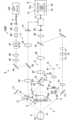
図1に、実施形態に係る眼科装置の光学系の構成例を示す。実施形態に係る眼科装置1000は、被検眼Eの検査を行うための光学系として、レフ測定光学系(屈折力測定光学系)と、OCT光学系とを含み、光学フィルターで波長分離を行うことによりレフ測定光学系の光路からOCT光学系の光路を分離する。<Configuration of Optical System>
1 shows an example of the configuration of an optical system of an ophthalmic apparatus according to an embodiment. The
眼科装置1000は、Zアライメント系1、XYアライメント系2、ケラト測定系3、固視投影系4、前眼部観察系5、レフ測定投射系6、レフ測定受光系7、及びOCT光学系8を含む。以下では、例えば、前眼部観察系が940nm~1000nmの光を用い、レフ測定光学系(レフ測定投射系6、レフ測定受光系7)が830nm~880nmの光を用い、固視投影系4が400nm~700nmの光を用い、OCT光学系8が840nm(中心波長)の光を用いる場合について説明する。 The
(前眼部観察系5)
前眼部観察系5は、被検眼Eの前眼部を動画撮影する。前眼部観察系5を経由する光学系において、撮像素子59の撮像面は瞳孔共役位置に配置されている。前眼部照明光源50は、被検眼Eの前眼部に照明光(例えば、赤外光)を照射する。被検眼Eの前眼部により反射された光は、対物レンズ51を通過し、ダイクロイックミラー52を透過し、絞り(テレセン絞り)53に形成された孔部を通過し、ハーフミラー23を透過し、リレーレンズ55及び56を通過し、ダイクロイックミラー76を透過する。ダイクロイックミラー76を透過した光は、結像レンズ58により撮像素子59(エリアセンサー)の撮像面に結像される。撮像素子59は、所定のレートで撮像及び信号出力を行う。撮像素子59の出力(映像信号)は、後述の処理部9に入力される。処理部9は、この映像信号に基づく前眼部像E´を後述の表示部10の表示画面10aに表示させる。前眼部像E´は、例えば赤外動画像である。(Anterior Eye Observation System 5)
The anterior
(Zアライメント系1)
Zアライメント系1は、前眼部観察系5の光軸方向(前後方向、Z方向)におけるアライメントを行うための光(赤外光)を被検眼Eに投射する。Zアライメント光源11から出力された光は、被検眼Eの角膜Crに投射され、角膜Crにより反射され、結像レンズ12によりラインセンサー13のセンサー面に結像される。角膜頂点の位置が前眼部観察系5の光軸方向に変化すると、ラインセンサー13のセンサー面における光の投射位置が変化する。処理部9は、ラインセンサー13のセンサー面における光の投射位置に基づいて被検眼Eの角膜頂点の位置を求め、これに基づき光学系を移動させる機構を制御してZアライメントを実行する。(Z alignment system 1)
The
(XYアライメント系2)
XYアライメント系2は、前眼部観察系5の光軸に直交する方向(左右方向(X方向)、上下方向(Y方向))のアライメントを行うための光(赤外光)を被検眼Eに照射する。XYアライメント系2は、ハーフミラー23により前眼部観察系5の光路から分岐された光路に設けられたXYアライメント光源21とコリメータレンズ22とを含む。XYアライメント光源21から出力された光は、コリメータレンズ22を通過し、ハーフミラー23により反射され、前眼部観察系5を通じて被検眼Eに投射される。被検眼Eの角膜Crによる反射光は、前眼部観察系5を通じて撮像素子59に導かれる。(XY alignment system 2)
The
この反射光に基づく像(輝点像)Brは前眼部像E´に含まれる。処理部9は、輝点像Brを含む前眼部像E´とアライメントマークALとを表示部の表示画面に表示させる。手動でXYアライメントを行う場合、ユーザは、アライメントマークAL内に輝点像Brを誘導するように光学系の移動操作を行う。自動でアライメントを行う場合、処理部9は、アライメントマークALに対する輝点像Brの変位がキャンセルされるように、光学系を移動させる機構を制御する。The image (bright spot image) Br based on this reflected light is included in the anterior eye image E'. The
(ケラト測定系3)
ケラト測定系3は、被検眼Eの角膜Crの形状を測定するためのリング状光束(赤外光)を角膜Crに投射する。ケラト板31は、対物レンズ51と被検眼Eとの間に配置されている。ケラト板31の背面側(対物レンズ51側)にはケラトリング光源32が設けられている。ケラトリング光源32からの光でケラト板31を照明することにより、被検眼Eの角膜Crにリング状光束が投射される。被検眼Eの角膜Crからの反射光(ケラトリング像)は撮像素子59により前眼部像E´とともに検出される。処理部9は、このケラトリング像を基に公知の演算を行うことで、角膜Crの形状を表す角膜形状パラメータを算出する。(Kerato measurement system 3)
The
(レフ測定投射系6、レフ測定受光系7)
レフ測定光学系は、屈折力測定に用いられるレフ測定投射系6及びレフ測定受光系7を含む。レフ測定投射系6は、屈折力測定用の光束(例えば、リング状光束)(赤外光)を眼底Efに投射する。レフ測定受光系7は、この光束の被検眼Eからの戻り光を受光する。レフ測定投射系6は、レフ測定受光系7の光路に設けられた孔開きプリズム65によって分岐された光路に設けられる。孔開きプリズム65に形成されている孔部は、瞳孔共役位置に配置される。レフ測定受光系7を経由する光学系において、撮像素子59の撮像面は眼底共役位置に配置される。(Reflex
The reflex measurement optical system includes a reflex
いくつかの実施形態では、レフ測定光源61は、高輝度光源であるSLD(Superluminescent Diode)光源である。レフ測定光源61は、光軸方向に移動可能である。レフ測定光源61は、眼底共役位置に配置される。レフ測定光源61から出力された光は、リレーレンズ62を通過し、円錐プリズム63の円錐面に入射する。円錐面に入射した光は偏向され、円錐プリズム63の底面から出射する。円錐プリズム63の底面から出射した光は、リング絞り64にリング状に形成された透光部を通過する。リング絞り64の透光部を通過した光(リング状光束)は、孔開きプリズム65の孔部の周囲に形成された反射面により反射され、ロータリープリズム66を通過し、フィルター70により反射される。後述のように、フィルター70は、波長分離を行うことによりレフ測定光学系の光路からOCT光学系の光路を分離するための光学素子である。フィルター70により反射された光は、ダイクロイックミラー52により反射され、対物レンズ51を通過し、被検眼Eに投射される。ロータリープリズム66は、眼底Efの血管や疾患部位に対するリング状光束の光量分布を平均化や光源に起因するスペックルノイズの低減のために用いられる。 In some embodiments, the reflex
眼底Efに投射されたリング状光束の戻り光は、対物レンズ51を通過し、ダイクロイックミラー52及びフィルター70により反射される。フィルター70により反射された戻り光は、ロータリープリズム66を通過し、孔開きプリズム65の孔部を通過し、リレーレンズ71を通過し、反射ミラー72により反射され、リレーレンズ73及び合焦レンズ74を通過する。合焦レンズ74は、レフ測定受光系7の光軸に沿って移動可能である。合焦レンズ74を通過した光は、反射ミラー75により反射され、ダイクロイックミラー76により反射され、結像レンズ58により撮像素子59の撮像面に結像される。処理部9は、撮像素子59からの出力を基に公知の演算を行うことで被検眼Eの屈折力値を算出する。例えば、屈折力値は、球面度数、乱視度数及び乱視軸角度を含む。 The return light of the ring-shaped light beam projected onto the fundus Ef passes through the
(固視投影系4)
フィルター70によりレフ測定光学系の光路から波長分離された光路に、後述のOCT光学系8が設けられる。ダイクロイックミラー83によりOCT光学系8の光路から分岐された光路に固視投影系4が設けられる。(Fixation projection system 4)
An OCT
固視投影系4は、固視標を被検眼Eに呈示する。処理部9による制御を受けた液晶パネル41は、固視標を表すパターンを表示する。液晶パネル41の画面上におけるパターンの表示位置を変更することにより、被検眼Eの固視位置を変更できる。被検眼Eの固視位置としては、眼底Efの黄斑部を中心とする画像を取得するための位置や、視神経乳頭を中心とする画像を取得するための位置や、黄斑部と視神経乳頭との間の眼底中心を中心とする画像を取得するための位置などがある。固視標を表すパターンの表示位置を任意に変更することが可能である。The fixation projection system 4 presents a fixation target to the subject's eye E. The
液晶パネル41からの光は、リレーレンズ42を通過し、ダイクロイックミラー83を透過し、リレーレンズ82を通過し、反射ミラー81により反射され、フィルター70を透過し、ダイクロイックミラー52により反射される。ダイクロイックミラー52により反射された光は、対物レンズ51を通過して眼底Efに投射される。液晶パネル41(又は液晶パネル41及びリレーレンズ42)は、光軸方向に移動可能である。 The light from the
(OCT光学系8)
OCT光学系8は、OCT計測を行うための光学系である。OCT計測よりも前に実施されたレフ測定結果に基づいて、光ファイバーf1の端面が眼底Efと光学系に共役となるように合焦レンズ87の位置が調整される。(OCT optical system 8)
The OCT
OCT光学系8は、フィルター70によりレフ測定光学系の光路から波長分離された光路に設けられる。上記の固視投影系4の光路は、ダイクロイックミラー83によりOCT光学系8の光路に結合される。それにより、OCT光学系8及び固視投影系4のそれぞれの光軸を同軸で結合することができる。The OCT
OCT光学系8は、OCTユニット100を含む。図2に示すように、OCTユニット100は、低コヒーレンス光を参照光と信号光に分割し、被検眼E(眼底Ef)を経由した信号光と参照光路を経由した参照光とを干渉させて干渉光を生成し、この干渉光のスペクトル成分を検出するように構成されている。この検出結果(検出信号)は処理部9に送られる。The OCT
OCTユニット100において、OCT光源101は、一般的なスペクトラルドメインタイプのOCT装置と同様に、低コヒーレンス光源を含む。OCT光源101は、広帯域の低コヒーレンス光L0を出力する。低コヒーレンス光L0は、例えば、近赤外領域の波長帯(中心波長が830nm、約800nm~900nmの波長範囲)を含み、数十マイクロメートル程度の時間的コヒーレンス長を有する。OCT光源101は、スーパールミネセントダイオード(Super Luminescent Diode:SLD)や、LEDや、SOA(Semiconductor Optical Amplifier)等の光出力デバイスを含んで構成される。 In the
OCT光源101から出力された低コヒーレンス光L0は、光ファイバー102によりファイバーカプラー103に導かれて測定光LSと参照光LRとに分割される。The low-coherence light L0 output from the OCT
参照光LRは、光ファイバー104により導かれて光減衰器(アッテネータ)105に到達する。光減衰器105は、公知の技術を用いて、処理部9の制御の下、光ファイバー104に導かれる参照光LRの光量を自動で調整する。光減衰器105により光量が調整された参照光LRは、光ファイバー104により導かれて偏波調整器(偏波コントローラ)106に到達する。偏波調整器106は、例えば、ループ状にされた光ファイバー104に対して外部から応力を与えることで、光ファイバー104内を導かれる参照光LRの偏光状態を調整する装置である。なお、偏波調整器106の構成はこれに限定されるものではなく、任意の公知技術を用いることが可能である。偏波調整器106により偏光状態が調整された参照光LRは、ファイバーカプラー109に到達する。The reference light LR is guided by the
ファイバーカプラー103により生成された測定光LSは、光ファイバーf1により導かれ、光路長変更部89を通過し、図1のコリメータレンズ90により平行光束とされる。光路長変更部89は、測定光LSの光路長を変更する。更に、測定光LSは、光スキャナー88、合焦レンズ87、リレーレンズ86及び85、及び反射ミラー84を経由してダイクロイックミラー83に到達する。光スキャナー88は、測定光LSを1次元的又は2次元的に偏向する。光スキャナー88は、例えば、第1ガルバノミラーと、第2ガルバノミラーとを含む。第1ガルバノミラーは、OCT光学系8の光軸に直交する水平方向に眼底Efをスキャンするように測定光LSを偏向する。第2ガルバノミラーは、OCT光学系8の光軸に直交する垂直方向に眼底Efをスキャンするように、第1ガルバノミラーにより偏向された測定光LSを偏向する。このような光スキャナー88による測定光LSの走査態様としては、例えば、水平スキャン、垂直スキャン、十字スキャン、放射スキャン、円スキャン、同心円スキャン、螺旋スキャンなどがある。The measurement light LS generated by the
測定光LSは、ダイクロイックミラー83により反射され、リレーレンズ82を通過し、反射ミラー81により反射され、フィルター70を透過し、ダイクロイックミラー52により反射される。ダイクロイックミラー52により反射された測定光LSは、対物レンズ51により屈折されて例えば眼底Efに照射される。測定光LSは、眼底Efの様々な深さ位置において散乱(反射を含む)される。眼底Efによる測定光LSの後方散乱光は、往路と同じ経路を逆向きに進行してファイバーカプラー103に導かれ、光ファイバー108を経由してファイバーカプラー109に到達する。 The measurement light LS is reflected by the
ファイバーカプラー109は、測定光LSの後方散乱光と、光ファイバー104を導かれてきた参照光LRとを干渉させる。これにより生成された干渉光LCは、光ファイバー110により導かれて出射端111から出射される。干渉光LCは、コリメータレンズ112により平行光束とされ、回折格子113により分光(スペクトル分解)され、集光レンズ114により集光されてCCDイメージセンサーなどの検出器115の受光面に投影される。なお、図2に示す回折格子113は透過型であるが、たとえば反射型の回折格子など、他の形態の分光素子を用いることも可能である。The
検出器115は、例えばラインセンサーであり、分光された干渉光LCの各スペクトル成分を検出して電荷に変換する。検出器115は、この電荷を蓄積して検出信号を生成し、これを処理部9に送る。 The
この実施形態ではマイケルソン型の干渉計を採用しているが、例えばマッハツェンダー型など任意のタイプの干渉計を適宜に採用することが可能である。また、検出器115として、CCDイメージセンサーに代えて、他の形態のイメージセンサー、たとえばCMOS(Complementary Metal Oxide Semiconductor)イメージセンサーなどを用いることが可能である。 Although a Michelson type interferometer is used in this embodiment, any type of interferometer such as a Mach-Zehnder type can be used as appropriate. Further, as the
処理部9は、レフ測定光学系を用いて得られた測定結果から屈折力値を算出し、算出された屈折力値に基づいて、眼底Efとレフ測定光源61と撮像素子59とが共役となる位置に、レフ測定光源61及び合焦レンズ74それぞれを光軸方向に移動させる。いくつかの実施形態では、処理部9は、レフ測定光源61及び合焦レンズ74の移動に連動して液晶パネル41をその光軸方向に移動させる。いくつかの実施形態では、処理部9は、合焦レンズ74の移動に連動してOCT光学系8の合焦レンズ87をその光軸方向に移動させる。 The
以上のように、OCT光学系8は、フィルター70によりレフ測定光学系の光路から波長分離された光路に設けられる。すなわち、フィルター70によりレフ測定光学系の光路から波長分離された光路に設けられた検査光学系は、干渉光学系を含む。干渉光学系は、光源からの所定の波長範囲の光を参照光と測定光とに分割し、被検眼に測定光を投射し、被検眼からの測定光の戻り光と参照光との干渉光を検出する。As described above, the OCT
例えば、孔開きプリズムを用いてレフ測定光学系の光路からOCT光学系8の光路を分離する場合、孔開きプリズムに形成された孔部に測定光を通過させるように光学系が構成されるため、測定光やその戻り光のケラレ等を考慮する必要が生じる。これに対して、フィルター70により波長分離を行うことで、孔開きプリズムを用いる場合に比べて各光学系で用いられる光の光量を増大させることができる。For example, when using a hole prism to separate the optical path of the OCT
フィルター70は、波長分離特性の変更が可能な光学フィルターである。波長分離特性は、入射光の波長の透過特性又は反射特性に対応する。波長分離特性には、カットオン波長、カットオフ波長、及び遮断領域などがある。いくつかの実施形態に係るフィルター70は、フィルターの種別を変更可能である。フィルターの種別には、狭帯域バンドパスフィルター、広帯域バンドパスフィルター、ショートパスフィルター、ロングパスフィルター、及び減光フィルターなどがある。この実施形態では、波長分離特性は、レフ測定に用いられる波長範囲の光及びOCT計測に用いられる波長範囲の光を、検査種別に応じて波長分離するように変更される。The
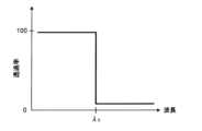
図3、図4A及び図4Bに、実施形態に係るフィルター70の説明図を示す。図3は、実施形態に係るフィルター70の構成例のブロック図を表す。図4Aは、図3の第1フィルター711の波長分離特性を模式的に表す。図4Bは、図3の第2フィルター712の波長分離特性を模式的に表す。図4A及び図4Bにおいて、横軸は波長を表し、縦軸は光の透過率を表す。 FIG. 3, FIG. 4A, and FIG. 4B show explanatory diagrams of the
図3に示すように、フィルター70は、互いに波長分離特性が異なる複数のフィルターを含むフィルター群710と、フィルター群710の複数のフィルター素子を移動(回転移動又は平行移動)させる移動機構720とを含む。移動機構720は、フィルター群710に含まれる複数のフィルターの少なくとも1つを移動させることによりレフ測定光学系の光路に選択的にフィルターを配置させる。 As shown in FIG. 3, the
この実施形態では、フィルター群710は、レフ測定用の第1フィルター711と、OCT計測用の第2フィルター712とを含む。レフ測定を行うときに第1フィルター711がレフ測定光学系の光路に配置され、OCT計測を行うときに第2フィルター712がレフ測定光学系の光路に配置される。いくつかの実施形態に係る第1フィルター711及び第2フィルター712の少なくとも一方は、ダイクロイックミラーである。In this embodiment, the
第1フィルター711は、図4Aに示すように第1波長分離特性を有する。第1波長分離特性は、カットオン波長(カットオフ波長)がλDであるショートパスフィルター(長波長カットフィルター)と同様の特性を有する。第1波長分離特性は、波長λDより短波長側が透過波長領域であり、波長λDより長波長側が反射波長領域であることを表す。第1フィルター711は、固視投影系4に用いる光の波長範囲(400nm~700nm)が透過波長領域となり、レフ測定光学系に用いる光の波長範囲(830nm~880nm)が反射波長領域となるような波長分離特性を有する。すなわち、OCT光学系8に用いる光の波長範囲は反射波長領域に含まれる。 The
第2フィルター712は、図4Bに示すように第1波長分離特性と異なる第2波長分離特性を有する。第2波長分離特性は、波長領域の全域が透過波長領域であることを表す。第2フィルター712は、固視投影系4に用いる光の波長範囲(400nm~700nm)とレフ測定光学系に用いる光の波長範囲(830nm~880nm)が透過波長領域となるような波長分離特性(波長透過特性)を有する。The
いくつかの実施形態では、図示しない保持部材により第1フィルター711及び第2フィルター712がレフ測定光学系の光路に対する交差方向に保持される。移動機構720は、当該交差方向に保持部材を移動させることにより第1フィルター711及び第2フィルター712をレフ測定光学系の光路に選択的に配置させる。 In some embodiments, the
いくつかの実施形態では、図示しないターレット板の円周方向に第1フィルター711及び第2フィルター712が保持される。ターレット板は、レフ測定光学系の光路(光軸)に対して略平行な回動軸を中心に回動可能であり、当該回動軸を中心としてレフ測定光学系の光路が通過する円周上に第1フィルター711及び第2フィルター712が配列される。移動機構720は、当該回動軸を中心にターレット板を回動させることにより第1フィルター711及び第2フィルター712をレフ測定光学系の光路に選択的に配置させる。In some embodiments, the
このように検査種別(検査内容)に応じてフィルター70の波長分離特性を変更することにより、構成を簡素化しつつ、レフ測定及びOCT計測それぞれにおいて光量の損失を抑えて高精度な検査や測定を行うことが可能になる。 By changing the wavelength separation characteristics of the
<処理系の構成>
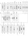
眼科装置1000の処理系の構成について説明する。眼科装置1000の処理系の機能的構成の例を図5に示す。図5は、眼科装置1000の処理系の機能ブロック図の一例を表す。<Processing system configuration>
The configuration of the processing system of the
処理部9は、眼科装置1000の各部を制御する。また、処理部9は、各種演算処理を実行可能である。処理部9は、プロセッサを含む。プロセッサの機能は、例えば、CPU(Central Processing Unit)、GPU(Graphics Processing Unit)、ASIC(Application Specific Integrated Circuit)、プログラマブル論理デバイス(例えば、SPLD(Simple Programmable Logic Device)、CPLD(Complex Programmable Logic Device)、FPGA(Field Programmable Gate Array))等の回路により実現される。処理部9は、例えば、記憶回路や記憶装置に格納されているプログラムを読み出し実行することで、実施形態に係る機能を実現する。The
処理部9は、制御部210と、演算処理部220とを含む。また、眼科装置1000は、移動機構200と、表示部270と、操作部280と、通信部290とを含む。The
移動機構200は、Zアライメント系1、XYアライメント系2、ケラト測定系3、固視投影系4、前眼部観察系5、レフ測定投射系6、レフ測定受光系7及びOCT光学系8等の光学系が収納されたヘッド部を前後左右方向に移動させるための機構である。例えば、移動機構200には、ヘッド部を移動するための駆動力を発生するアクチュエータと、この駆動力を伝達する伝達機構とが設けられる。アクチュエータは、例えばパルスモータにより構成される。伝達機構は、例えば歯車の組み合わせやラック・アンド・ピニオンなどによって構成される。制御部210(主制御部211)は、アクチュエータに対して制御信号を送ることにより移動機構200に対する制御を行う。 The moving
(制御部210)
制御部210は、プロセッサを含み、眼科装置の各部を制御する。制御部210は、主制御部211と、記憶部212とを含む。記憶部212には、眼科装置を制御するためのコンピュータプログラムがあらかじめ格納される。コンピュータプログラムには、光源制御用プログラム、検出器制御用プログラム、光スキャナー制御用プログラム、光学系制御用プログラム、演算処理用プログラム及びユーザインターフェイス用プログラムなどが含まれる。このようなコンピュータプログラムに従って主制御部211が動作することにより、制御部210は制御処理を実行する。(Control unit 210)
The
主制御部211は、測定制御部として眼科装置の各種制御を行う。Zアライメント系1に対する制御には、Zアライメント光源11の制御、ラインセンサー13の制御などがある。Zアライメント光源11の制御には、光源の点灯、消灯、光量調整、絞り調整などがある。ラインセンサー13の制御には、検出素子の露光調整やゲイン調整や検出レート調整などがある。それにより、Zアライメント光源11の点灯と非点灯とが切り替えられたり、光量が変更されたりする。主制御部211は、ラインセンサー13により検出された信号を取り込み、取り込まれた信号に基づいてラインセンサー13に対する光の投影位置を特定する。主制御部211は、特定された投影位置に基づいて被検眼Eの角膜頂点の位置を求め、これに基づき移動機構200を制御してヘッド部を前後方向に移動させる(Zアライメント)。The
XYアライメント系2に対する制御には、XYアライメント光源21の制御などがある。XYアライメント光源21の制御には、光源の点灯、消灯、光量調整、絞り調整などがある。それにより、XYアライメント光源21の点灯と非点灯とが切り替えられたり、光量が変更されたりする。主制御部211は、撮像素子59により検出された信号を取り込み、取り込まれた信号に基づいてXYアライメント光源21からの光の戻り光に基づく輝点像の位置を特定する。主制御部211は、所定の目標位置(例えば、アライメントマークALの中心位置)に対する輝点像Brの位置との変位がキャンセルされるように移動機構200を制御してヘッド部を左右上下方向に移動させる(XYアライメント)。 Control of the
ケラト測定系3に対する制御には、ケラトリング光源32の制御などがある。ケラトリング光源32の制御には、光源の点灯、消灯、光量調整、絞り調整などがある。それにより、ケラトリング光源32の点灯と非点灯とが切り替えられたり、光量が変更されたりする。主制御部211は、撮像素子59により検出されたケラトリング像に対する公知の演算を演算処理部220に実行させる。それにより、被検眼Eの角膜形状パラメータが求められる。 Control of the
固視投影系4に対する制御には、液晶パネル41の制御などがある。液晶パネル41の制御には、固視標の表示のオン・オフや、固視標の表示位置の切り替えなどがある。それにより、被検眼Eの眼底Efに固視標が投影される。例えば、固視投影系4は、液晶パネル41(又は液晶パネル41及びリレーレンズ42)を光軸方向に移動する移動機構を含む。この移動機構には、移動機構200と同様に、当該移動機構を移動するための駆動力を発生するアクチュエータと、この駆動力を伝達する伝達機構とが設けられる。主制御部211は、アクチュエータに対して制御信号を送ることにより移動機構に対する制御を行い、少なくとも液晶パネル41を光軸方向に移動させる。それにより、液晶パネル41と眼底Efとが光学的に共役となるように液晶パネル41の位置が調整される。 Control of the fixation projection system 4 includes control of the
フィルター70に対する制御には、フィルター70の波長分離特性の変更制御などがある。具体的には、主制御部211は、検査種別に応じて、図3に示す移動機構720を制御することにより、レフ測定光学系の光路に第1フィルター711及び第2フィルター712を選択的に配置させる。 Control over the
いくつかの実施形態では、レフ測定光源61の点灯指示を受け、主制御部211は、フィルター70を制御して、レフ測定光学系の光路に第1フィルター711を自動で配置させる。この場合、主制御部211は、OCT光源101の消灯制御を自動で行ってもよい。In some embodiments, upon receiving an instruction to turn on the reflex
いくつかの実施形態では、OCT光源101の点灯指示を受け、主制御部211は、フィルター70を制御して、レフ測定光学系の光路に第2フィルター712を自動で配置させる。この場合、主制御部211は、レフ測定光源61の消灯制御を自動で行ってもよい。 In some embodiments, upon receiving an instruction to turn on the OCT
前眼部観察系5に対する制御には、前眼部照明光源50の制御、撮像素子59の制御などがある。前眼部照明光源50の制御には、光源の点灯、消灯、光量調整、絞り調整などがある。それにより、前眼部照明光源50の点灯と非点灯とが切り替えられたり、光量が変更されたりする。撮像素子59の制御には、撮像素子59の露光調整やゲイン調整や検出レート調整などがある。主制御部211は、撮像素子59により検出された信号を取り込み、取り込まれた信号に基づく画像の形成等の処理を演算処理部220に実行させる。 Control of the anterior eye
レフ測定投射系6に対する制御には、レフ測定光源61の制御、ロータリープリズム66の制御などがある。レフ測定光源61の制御には、光源の点灯、消灯、光量調整、絞り調整などがある。それにより、レフ測定光源61の点灯と非点灯とが切り替えられたり、光量が変更されたりする。例えば、レフ測定投射系6は、レフ測定光源61を光軸方向に移動する移動機構を含む。この移動機構には、移動機構200と同様に、当該移動機構を移動するための駆動力を発生するアクチュエータと、この駆動力を伝達する伝達機構とが設けられる。主制御部211は、アクチュエータに対して制御信号を送ることにより移動機構に対する制御を行い、レフ測定光源61を光軸方向に移動させる。ロータリープリズム66の制御には、ロータリープリズム66の回転制御などがある。例えば、ロータリープリズム66を回転させる回転機構が設けられており、主制御部211は、この回転機構を制御することによりロータリープリズム66を回転させる。 Control of the reflex
レフ測定受光系7に対する制御には、合焦レンズ74の制御などがある。合焦レンズ74の制御には、合焦レンズ74の光軸方向への移動制御などがある。例えば、レフ測定受光系7は、合焦レンズ74を光軸方向に移動する移動機構を含む。この移動機構には、移動機構200と同様に、当該移動機構を移動するための駆動力を発生するアクチュエータと、この駆動力を伝達する伝達機構とが設けられる。主制御部211は、アクチュエータに対して制御信号を送ることにより移動機構に対する制御を行い、合焦レンズ74を光軸方向に移動させる。主制御部211は、レフ測定光源61と眼底Efと撮像素子59とが光学的に共役となるように、例えば被検眼Eの屈折力に応じてレフ測定光源61及び合焦レンズ74をそれぞれ光軸方向に移動させることが可能である。The control of the reflex measurement
OCT光学系8に対する制御には、OCT光源101の制御、光路長変更部89の制御、光スキャナー88の制御、合焦レンズ87の制御、検出器115の制御などがある。OCT光源101の制御には、光源の点灯、消灯、光量調整、絞り調整などがある。光路長変更部89は、例えば、入射光を、入射方向と平行で、且つ反対方向に反射するコーナーキューブと、コーナーキューブを入射光の光路に沿って移動する移動機構とを含む。光路長変更部89の制御には、移動機構に対する制御などがある。この移動機構には、移動機構200と同様に、当該移動機構を移動するための駆動力を発生するアクチュエータと、この駆動力を伝達する伝達機構とが設けられる。主制御部211は、アクチュエータに対して制御信号を送ることにより移動機構に対する制御を行い、コーナーキューブを入射光の光路に沿って移動させる。光スキャナー88の制御には、第1ガルバノミラーによる走査位置や走査範囲や走査速度の制御、第2ガルバノミラーによる走査位置や走査範囲や走査速度の制御などがある。合焦レンズ87の制御には、合焦レンズ87の光軸方向への移動制御などがある。例えば、OCT光学系8は、合焦レンズ87を光軸方向に移動する移動機構を含む。この移動機構には、移動機構200と同様に、当該移動機構を移動するための駆動力を発生するアクチュエータと、この駆動力を伝達する伝達機構とが設けられる。主制御部211は、アクチュエータに対して制御信号を送ることにより移動機構に対する制御を行い、合焦レンズ87を光軸方向に移動させる。主制御部211は、例えば、合焦レンズ74の移動に連動して合焦レンズ87を移動させた後、干渉信号の強度に基づいて合焦レンズ87だけを移動させるようにしてもよい。検出器115の制御には、検出素子の露光調整やゲイン調整や検出レート調整などがある。主制御部211は、検出器115により検出された信号をサンプリングし、サンプリングされた信号に基づく画像の形成等の処理を演算処理部220(画像形成部222)に実行させる。The control of the OCT
いくつかの実施形態では、OCT光学系8は、参照光LRの光路長を変更する光路長変更部を含む。主制御部211は、光路長変更部を制御することにより参照光LRの光路長を変更する。 In some embodiments, the OCT
また、主制御部211は、記憶部212にデータを書き込む処理や、記憶部212からデータを読み出す処理を行う。The
(記憶部212)
記憶部212は、各種のデータを記憶する。記憶部212に記憶されるデータとしては、例えば他覚測定の測定結果、断層像の画像データ、眼底像の画像データ、被検眼情報などがある。被検眼情報は、患者IDや氏名などの被検者に関する情報や、左眼/右眼の識別情報などの被検眼に関する情報を含む。また、記憶部212には、眼科装置を動作させるための各種プログラムやデータが記憶されている。(Storage unit 212)
The
(演算処理部220)
演算処理部220は、眼屈折力算出部221と、画像形成部222と、データ処理部223とを含む。(Calculation processing unit 220)
The
眼屈折力算出部221は、レフ測定投射系6により眼底Efに投影されたリング状光束(リング状の測定パターン)の戻り光を撮像素子59が受光することにより得られたリング像(パターン像)を解析する。例えば、眼屈折力算出部221は、得られたリング像が描出された画像における輝度分布からリング像の重心位置を求め、この重心位置から放射状に延びる複数の走査方向に沿った輝度分布を求め、この輝度分布からリング像を特定する。続いて、眼屈折力算出部221は、特定されたリング像の近似楕円を求め、この近似楕円の長径及び短径を公知の式に代入することによって球面度数、乱視度数及び乱視軸角度を求める。或いは、眼屈折力算出部221は、基準パターンに対するリング像の変形及び変位に基づいて眼屈折力のパラメータを求めることができる。The ocular refractive
また、眼屈折力算出部221は、前眼部観察系5により取得されたケラトリング像に基づいて、角膜屈折力、角膜乱視度及び角膜乱視軸角度を算出する。例えば、眼屈折力算出部221は、ケラトリング像を解析することにより角膜前面の強主経線や弱主経線の角膜曲率半径を算出し、角膜曲率半径に基づいて上記パラメータを算出する。The eye refractive
画像形成部222は、検出器115により検出された信号に基づいて、眼底Efの断層像の画像データを形成する。すなわち、画像形成部222は、干渉光学系による干渉光LCの検出結果に基づいて被検眼Eの画像データを形成する。この処理には、従来のスペクトラルドメインタイプのOCTと同様に、フィルター処理、FFT(Fast Fourier Transform)などの処理が含まれている。このようにして取得される画像データは、複数のAライン(被検眼E内における各測定光LSの経路)における反射強度プロファイルを画像化することにより形成された一群の画像データを含むデータセットである。The
画質を向上させるために、同じパターンでのスキャンを複数回繰り返して収集された複数のデータセットを重ね合わせる(加算平均する)ことができる。 To improve image quality, multiple data sets collected by scanning the same pattern multiple times can be overlapped (averaged).
データ処理部223は、画像形成部222により形成された断層像に対して各種のデータ処理(画像処理)や解析処理を施す。例えば、データ処理部223は、画像の輝度補正や分散補正等の補正処理を実行する。また、データ処理部223は、前眼部観察系5を用い得られた画像(前眼部像等)に対して各種の画像処理や解析処理を施す。The
データ処理部223は、断層像の間の画素を補間する補間処理などの公知の画像処理を実行することにより、被検眼Eのボリュームデータ(ボクセルデータ)を形成することができる。ボリュームデータに基づく画像を表示させる場合、データ処理部223は、このボリュームデータに対してレンダリング処理を施して、特定の視線方向から見たときの擬似的な3次元画像を形成する。The
(表示部270、操作部280)
表示部270は、ユーザインターフェイス部として、制御部210による制御を受けて情報を表示する。表示部270は、図1などに示す表示部10を含む。(
The
操作部280は、ユーザインターフェイス部として、眼科装置を操作するために使用される。操作部280は、眼科装置に設けられた各種のハードウェアキー(ジョイスティック、ボタン、スイッチなど)を含む。また、操作部280は、タッチパネル式の表示画面10aに表示される各種のソフトウェアキー(ボタン、アイコン、メニューなど)を含んでもよい。 The
表示部270及び操作部280の少なくとも一部が一体的に構成されていてもよい。その典型例として、タッチパネル式の表示画面10aがある。At least a portion of the
(通信部290)
通信部290は、図示しない外部装置と通信するための機能を有する。通信部290は、外部装置との接続形態に応じた通信インターフェイスを備える。外部装置の例として、レンズの光学特性を測定するための眼鏡レンズ測定装置がある。眼鏡レンズ測定装置は、被検者が装用する眼鏡レンズの度数などを測定し、この測定データを眼科装置1000に入力する。また、外部装置は、任意の眼科装置、記録媒体から情報を読み取る装置(リーダ)や、記録媒体に情報を書き込む装置(ライタ)などでもよい。更に、外部装置は、病院情報システム(HIS)サーバ、DICOM(Digital Imaging and COmmunication in Medicine)サーバ、医師端末、モバイル端末、個人端末、クラウドサーバなどでもよい。通信部290は、例えば処理部9に設けられていてもよい。(Communication Department 290)
The
レフ測定光学系による屈折力測定で用いられる光の波長範囲(例えば、830nm~880nm)は、実施形態に係る「第1波長範囲」の一例である。レフ測定光学系(レフ測定投射系6、レフ測定受光系7)は、実施形態に係る「屈折力測定光学系」の一例である。OCT光学系8によるOCT計測で用いられる光の波長範囲(例えば、中心波長が840nmである約800nm~900nmの波長範囲)は、実施形態に係る「第2波長範囲」の一例である。OCT光学系8は、実施形態に係る「検査光学系」の一例である。フィルター70は、実施形態に係る「光路分離部」の一例である。第1フィルター711及び第2フィルター712は、実施形態に係る「波長分離素子」の一例である。固視投影系4は、実施形態に係る「固視光学系」の一例である。ダイクロイックミラー83は、実施形態に係る「光路結合部材」の一例である。OCTユニット100に含まれる光学系は、実施形態に係る「干渉光学系」の一例である。The wavelength range of light used in refractive power measurement by the refraction measurement optical system (e.g., 830 nm to 880 nm) is an example of a "first wavelength range" according to the embodiment. The refraction measurement optical system (refraction
<動作例>
実施形態に係る眼科装置1000の動作について説明する。<Example of operation>
The operation of the
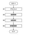
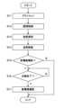
図6に、眼科装置1000の動作の一例を示す。図6は、眼科装置1000の動作例のフロー図を表す。Figure 6 shows an example of the operation of the
(S1:アライメント)
図示しない顔受け部に被検者の顔が固定された状態で、検者が操作部280に対して所定の操作を行うことで、眼科装置1000は、アライメントを実行する。(S1: Alignment)
The
具体的には、主制御部211は、Zアライメント光源11やXYアライメント光源21を点灯させる。処理部9は、撮像素子59の撮像面上の前眼部像の撮像信号を取得し、表示部270に前眼部像を表示させる。その後、図1に示す光学系が被検眼Eの検査位置に移動される。検査位置とは、被検眼Eの検査を十分な精度内で行うことが可能な位置である。前述のアライメント(Zアライメント系1及びXYアライメント系2と前眼部観察系5とによるアライメント)を介して被検眼Eが検査位置に配置される。光学系の移動は、ユーザによる操作若しくは指示又は制御部210による指示にしたがって、制御部210によって実行される。すなわち、被検眼Eの検査位置への光学系の移動と、他覚測定を行うための準備とが行われる。 Specifically, the
また、主制御部211は、レフ測定光源61と、合焦レンズ74と、液晶パネル41をそれぞれの光軸に沿って原点の位置(例えば、0Dに相当する位置)に移動させる。 Further, the
(S2:固視制御)
ステップS2の処理に先立って、主制御部211は、フィルター70を制御することにより、レフ測定用の第1フィルター711をレフ測定光学系の光路に配置させる。それにより、固視投影系4からの光がフィルター70を透過し、レフ測定光学系に用いられる光がフィルター70により反射される。(S2: Fixation control)
Prior to the processing of step S2, the
ステップS2では、主制御部211は、所望の固視位置に対応した表示位置に固視標を示すパターンを液晶パネル41に表示させる。それにより、所望の固視位置に被検眼Eを注視させる。 In step S2, the
なお、ステップS2における固視制御に続いて、眼科装置1000は、ケラト測定を実行してもよい。この場合、主制御部211は、ケラトリング光源32を点灯させる。ケラトリング光源32から光が出力されると、被検眼Eの角膜Crに角膜形状測定用のリング状光束が投射される。眼屈折力算出部221は、撮像素子59によって取得された像に対して演算処理を施すことにより、角膜曲率半径を算出し、算出された角膜曲率半径から角膜屈折力、角膜乱視度及び角膜乱視軸角度を算出する。制御部210では、算出された角膜屈折力などが記憶部212に記憶される。主制御部211からの指示、又は操作部280に対するユーザの操作若しくは指示により、眼科装置1000の動作はステップS3に移行する。Following the fixation control in step S2, the
(S3:他覚測定)
次に、主制御部211は、液晶パネル41を制御することにより固視標を被検眼Eに投影させ、レフ測定を実行させる。(S3: Objective measurement)
Next, the
レフ測定では、主制御部211は、前述のようにレフ測定のためのリング状の測定パターン光束を被検眼Eに投射させる。被検眼Eからの測定パターン光束の戻り光に基づくリング像が撮像素子59の撮像面に結像される。主制御部211は、撮像素子59により検出された眼底Efからの戻り光に基づくリング像を取得できたか否かを判定する。例えば、主制御部211は、撮像素子59により検出された戻り光に基づく像のエッジの位置(画素)を検出し、像の幅(外径と内径との差)が所定値以上であるか否かを判定する。或いは、主制御部211は、所定の高さ(リング径)以上の点(像)に基づいてリングを形成できるか否かを判定することにより、リング像を取得できたか否かを判定してもよい。 In the reflex measurement, the
リング像を取得できたと判定されたとき、眼屈折力算出部221は、被検眼Eに投射された測定パターン光束の戻り光に基づくリング像を公知の手法で解析し、仮の球面度数S及び仮の乱視度数Cを求める。主制御部211は、求められた仮の球面度数S及び乱視度数Cに基づき、レフ測定光源61、合焦レンズ74、及び液晶パネル41を等価球面度数(S+C/2)の位置(仮の遠点に相当する位置)へ移動させる。主制御部211は、その位置から液晶パネル41を更に雲霧位置に移動させた後、本測定としてレフ測定投射系6及びレフ測定受光系7を制御することによりリング像を再び取得させる。主制御部211は、前述と同様に得られたリング像の解析結果と合焦レンズ74の移動量から球面度数、乱視度数及び乱視軸角度を眼屈折力算出部221に算出させる。When it is determined that the ring image has been acquired, the eye refractive
また、眼屈折力算出部221は、求められた球面度数及び乱視度数から被検眼Eの遠点に相当する位置(本測定により得られた遠点に相当する位置)を求める。主制御部211は、求められた遠点に相当する位置に液晶パネル41を移動させる。制御部210では、合焦レンズ74の位置や算出された球面度数などが記憶部212に記憶される。主制御部211からの指示、又は操作部280に対するユーザの操作若しくは指示により、眼科装置1000の動作はステップS4に移行する。The eye refractive
リング像を取得できないと判定されたとき、主制御部211は、強度屈折異常眼である可能性を考慮して、レフ測定光源61及び合焦レンズ74をあらかじめ設定したステップでマイナス度数側(例えば-10D)、プラス度数側(例えば+10D)へ移動させる。主制御部211は、レフ測定受光系7を制御することにより各位置でリング像を検出させる。それでもリング像を取得できないと判定されたとき、主制御部211は、所定の測定エラー処理を実行する。このとき、眼科装置1000の動作はステップS4に移行してもよい。制御部210では、レフ測定結果が得られなかったことを示す情報が記憶部212に記憶される。When it is determined that the ring image cannot be obtained, the
上記のように、OCT光学系8の合焦レンズ87は、レフ測定光源61や合焦レンズ74の移動に連動して光軸方向に移動される。 As described above, the focusing
(S4:断層像撮影)
ステップS4の処理に先立って、主制御部211は、フィルター70を制御することにより、OCT計測用の第2フィルター712をレフ測定光学系の光路に配置させる。それにより、固視投影系4からの光とOCT光学系8で用いられる光がフィルター70を透過する状態になる。(S4: Tomographic imaging)
Prior to the processing of step S4, the
ステップS4では、主制御部211は、液晶パネル41を制御することにより固視標を被検眼Eに投影させ、OCT計測を実行させる。In step S4, the
主制御部211は、OCT光源101を点灯させ、光スキャナー88を制御することにより眼底Efの所定の部位を測定光LSでスキャンさせる。測定光LSのスキャンにより得られた検出信号は画像形成部222に送られる。画像形成部222は、得られた検出信号から眼底Efの断層像を形成する。以上で、眼科装置1000の動作は、終了となる(エンド)。 The
以上説明したように、レフ測定光学系の光路に波長分離特性が変更可能なフィルター70を配置し、レフ測定用の波長分離特性とOCT計測用の波長分離特性とを切り替えつつレフ測定光学系の光路からOCT光学系8の光路が波長分離される。それにより、レフ測定に用いられる光の波長範囲とOCT計測に用いられる光の波長範囲が重複している場合であっても、簡素な構成で、レフ測定及びOCT計測のそれぞれにおいて光量の損失を大幅に低減し、測定や計測の精度を向上させることが可能になる。As described above, a
[変形例]
実施形態に係る眼科装置1000の光学系の構成は図1に示す構成に限定されるものではない。[Modified example]
The configuration of the optical system of the
<光学系の構成>
図7に、実施形態の変形例に係る眼科装置の光学系の構成例を示す。図7において、図1と同様の部分には同一符号を付し、適宜説明を省略する。<Configuration of Optical System>
7 shows an example of the configuration of an optical system of an ophthalmic apparatus according to a modified embodiment of the present invention. In Fig. 7, the same reference numerals are used for the same parts as in Fig. 1, and the description thereof will be omitted as appropriate.
変形例に係る眼科装置1000aの構成が眼科装置1000の構成と異なる点は、OCT光学系8に代えて検査光学系8aが設けられている点と、処理部9に代えて検査光学系8aを制御する処理部9aが設けられている点である。 The configuration of the
検査光学系8aの少なくとも一部は、異なる検査又は計測を行うための別の光学系に入れ替え可能に構成されている。具体的には、検査光学系8aの少なくとも一部は、選択的に装着可能な2以上の測定ユニットのいずれかに含まれる光学系に交換可能に構成されている。2以上の測定ユニットは、光源からの参照光と測定光とに分割し、被検眼に測定光を投射し、被検眼からの測定光の戻り光と参照光との干渉光を検出する干渉光学系を含む第1測定ユニットと、被検眼に視標光を投影する視標投影系を含む第2測定ユニットとを含む。すなわち、実施形態に係る検査光学系8aは、図1に示すダイクロイックミラー83からOCTユニット100までの光学系を含む第1測定ユニット及び図7に示す光学系を含む第2測定ユニットのうちいずれか1つを装着可能に構成されている。 At least a portion of the inspection
従って、フィルター70は、図1に示すように第1測定ユニットが装着されている場合にレフ測定光学系の光路からOCT光学系8の光路を波長分離する。また、フィルター70は、図7に示すように第2測定ユニットが装着されている場合にレフ測定光学系の光路から視標投影系の光路を波長分離する。なお、自覚検査を行うとき、フィルター70は、レフ測定を行うときと同じ波長分離特性でレフ測定光学系の光路から視標投影系の光路を波長分離する。すなわち、第1測定ユニットが装着されているとき第1フィルター711がレフ測定光学系の光路に配置され、第2測定ユニットが装着されているときも第1フィルター711がレフ測定光学系の光路に配置される。なお、視標投影系による自覚検査を行うとき、フィルター70の波長分離特性は、視標光を対物レンズ51に導くように変更されてよい。 Therefore, the
図7に示すように第2測定ユニット300が装着されている場合、視標投影系は、対物レンズ51を介して自覚検査用の視標等の各種視標を被検眼Eに投影する。液晶パネル306は、処理部9aからの制御を受け、視標を表すパターンを表示する。液晶パネル306から出力された光(例えば400nm~700nmの波長範囲の光、可視光)は、リレーレンズ305、合焦レンズ304、及びリレーレンズ303を通過し、反射ミラー302により反射され、ダイクロイックミラー301により反射される。ダイクロイックミラー301により反射された光は、リレーレンズ82を通過し、反射ミラー81により反射され、フィルター70を透過し、ダイクロイックミラー52により反射される。ダイクロイックミラー52により反射された光は、対物レンズ51を通過して眼底Efに投影される。合焦レンズ304は、視標投影系の光軸に沿って移動可能である。液晶パネル306と眼底Efとが光学的に共役となるように合焦レンズ304の位置が調整される。 When the
以上のように、視標投影系は、フィルター70によりレフ測定光学系の光路から波長分離された光路に設けられる。すなわち、フィルター70によりレフ測定光学系の光路から波長分離された光路に設けられた検査光学系は、被検眼に所定の波長範囲の視標光を投射する視標投影系を含む。 As described above, the target projection system is provided in an optical path that is wavelength-separated from the optical path of the reflex measuring optical system by the
いくつかの実施形態に係るダイクロイックミラー301は、図1に示すダイクロイックミラー83である。いくつかの実施形態に係る反射ミラー302は、図1に示す反射ミラー84である。In some embodiments, the dichroic mirror 301 is the
<処理系の構成>
眼科装置1000aの処理系の構成について説明する。眼科装置1000aの処理系の機能的構成の例を図8に示す。図8において、図5と同様の部分には同一符号を付し、適宜説明を省略する。<Processing system configuration>
The configuration of the processing system of the
処理部9aは、処理部9による処理に加えて、視標投影系に対する制御処理を行うことができる。処理部9aは、制御部210aと、演算処理部220とを含む。制御部210aは、主制御部211aと、記憶部212aとを含む。 In addition to the processing performed by the
主制御部211aは、第1測定ユニットが装着されているとき上記の実施形態と同様にOCT光学系8に対する制御を行い、第2測定ユニットが装着されているとき視標投影系に対する制御を行う。The
視標投影系に対する制御には、液晶パネル306の制御や、合焦レンズ304の制御などがある。液晶パネル306の制御には、視標の表示のオン・オフや、指標を表すパターンの切り替えなどがある。それにより、被検眼Eの眼底Efに視標が投影される。合焦レンズ304の制御には、合焦レンズ304の光軸方向への移動制御などがある。例えば、視標投影系は、合焦レンズ304を光軸方向に移動する移動機構を含む。この移動機構には、移動機構200と同様に、当該移動機構を移動するための駆動力を発生するアクチュエータと、この駆動力を伝達する伝達機構とが設けられる。主制御部211aは、アクチュエータに対して制御信号を送ることにより移動機構に対する制御を行い、合焦レンズ304を光軸方向に移動させる。それにより、液晶パネル306と眼底Efとが光学的に共役となるように合焦レンズ304の位置が調整される。 Control of the visual target projection system includes control of the
視標投影系は、実施形態に係る「自覚検査光学系」の一例である。視標投影系による自覚検査で用いられる光の波長範囲(例えば、400nm~700nm)は、実施形態に係る「第2波長範囲」の一例である。 The optotype projection system is an example of a "subjective inspection optical system" according to the embodiment. The wavelength range of light (for example, 400 nm to 700 nm) used in the subjective test using the optotype projection system is an example of the "second wavelength range" according to the embodiment.
<動作例>
実施形態の変形例に係る眼科装置1000aの動作について説明する。<Operation example>
The operation of the
図9に、眼科装置1000aの動作の一例を示す。図9は、眼科装置1000aの動作例のフロー図を表す。図9では、事前に第2測定ユニットが装着されているものとする。Figure 9 shows an example of the operation of the
(S11:アライメント)
眼科装置1000aは、ステップS1と同様に、アライメントを実行する。(S11: Alignment)
The
(S12:固視制御)
ステップS12の処理に先立って、主制御部211aは、フィルター70を制御することにより、レフ測定用の第1フィルター711をレフ測定光学系の光路に配置させる。(S12: Fixation control)
Prior to the process in step S12, the
ステップS12では、主制御部211aは、ステップS2と同様に、所望の固視位置に対応した表示位置に固視標を示すパターンを液晶パネル41に表示させる。In step S12, the
ステップS2と同様に、ステップS12における固視制御に続いて、眼科装置1000aは、ケラト測定を実行してもよい。Similar to step S2, following fixation control in step S12, the
(S13:他覚測定)
次に、主制御部211aは、ステップS3と同様に、液晶パネル41を制御することにより固視標を被検眼Eに投影させ、レフ測定を実行させる。(S13: Objective measurement)
Next, as in step S3, the
(S14:自覚検査)
続いて、主制御部211aは、例えば、操作部280に対するユーザの指示に基づき、液晶パネル306を制御することにより所望の視標を表示させる。また、主制御部211aは、他覚測定の結果に応じた位置に合焦レンズ304を移動する。主制御部211aは、操作部280に対するユーザの指示に応じた位置に合焦レンズ304を移動させてもよい。(S14: Subjective test)
Next, the
被検者は、眼底Efに投射された視標に対する応答を行う。例えば、視力測定用の視標の場合には、被検者の応答により被検眼の視力値が決定される。視標の選択とそれに対する被検者の応答が、検者又は主制御部211aの判断により繰り返し行われる。検者又は主制御部211aは、被検者からの応答に基づいて視力値或いは処方値(S、C、A)を決定する。 The subject responds to the optotype projected onto the fundus Ef. For example, in the case of an optotype for visual acuity measurement, the visual acuity value of the eye to be examined is determined based on the response of the examinee. The selection of the optotype and the response of the subject to the optotype are repeated based on the judgment of the examiner or the
(S15:断層像撮影?)
次に、主制御部211aは、被検眼Eの眼底Efの断層像を撮影するか否かを判定する。主制御部211aは、操作部280に対するユーザの操作内容に基づいて断層像を撮影するか否かを判定することができる。(S15: Tomographic imaging?)
Next, the
断層像を撮影すると判定されたとき(S15:Y)、眼科装置1000aの動作はステップS16に移行する。断層像を撮影しないと判定されたとき(S15:N)、眼科装置1000aの動作は終了である(エンド)。When it is determined that a tomographic image is to be captured (S15: Y), the operation of the
(S16:交換完了?)
ステップS15において断層像を撮影すると判定されたとき(S15:Y)、主制御部211aは、検査光学系8aにおいて第2測定ユニットが取り外されて第1測定ユニットが装着されたか否かを判定する。例えば、眼科装置1000aには、測定ユニットの装着状態と装着された測定ユニットの種別を判別するためのセンサーやマイクロスイッチが設けられている。主制御部211aは、センサーによる検出結果やマイクロスイッチの状態に基づいて測定ユニットの装着状態と装着された測定ユニットの種別とを特定することが可能である。(S16: Exchange completed?)
When it is determined in step S15 that a tomographic image is to be taken (S15: Y), the
例えば、測定ユニットの交換が完了したと判定されるまで、眼科装置1000aは待機する(S16:N)。第1測定ユニットが装着されて測定ユニットの交換が完了したと判定されたとき(S16:Y)、眼科装置1000aの動作はステップS17に移行する。 For example, the
(S17:断層像撮影)
ステップS17の処理に先立って、主制御部211aは、フィルター70を制御することにより、OCT計測用の第2フィルター712をレフ測定光学系の光路に配置させる。(S17: Tomographic imaging)
Prior to the processing of step S17, the
ステップS17では、主制御部211aは、ステップS4と同様に、液晶パネル41を制御することにより固視標を被検眼Eに投影させ、OCT計測を実行させる。以上で、眼科装置1000の動作は、終了となる(エンド)。In step S17, the
以上説明したように、フィルター70により波長分離された光路に、測定ユニットの交換により光学系の変更が可能な検査光学系8aを設けるようにしたので、レフ測定光学系をベースにOCT計測や自覚検査が可能な眼科装置の小型化を図ることが可能になる。いくつかの実施形態では、第2測定ユニットが視野検査を行うための公知の光学系を含み、レフ測定光学系をベースにOCT計測や視野検査が可能である。As described above, an examination
上記の実施形態では、レフ測定光学系は、フィルター70の反射光路に配置され、OCT光学系8(検査光学系)は、フィルター70の透過光路に配置される場合について説明した。この場合、フィルター70の波長分離特性は、レフ測定を行うとき、第1波長範囲の光を反射させ、且つ、第2波長範囲の光を透過させ、OCT計測を行うとき、第1波長範囲の光及び第2波長範囲の光を透過させるように変更される。In the above embodiment, the case has been described in which the reflectance measurement optical system is disposed in the reflected light path of the
いくつかの実施形態では、レフ測定光学系は、フィルター70の透過光路に配置され、OCT光学系8(検査光学系)は、フィルター70の反射光路に配置されてもよい。この場合、フィルター70の波長分離特性は、レフ測定を行うとき、第1波長範囲の光を透過させ、且つ、第2波長範囲の光を反射させ、OCT計測を行うとき、第1波長範囲の光及び第2波長範囲の光を反射させるように変更される。 In some embodiments, the reflex measurement optical system may be placed in the transmission optical path of the
[作用・効果]
実施形態又は変形例に係る眼科装置の作用及び効果について説明する。[Action/Effect]
The functions and effects of the ophthalmologic apparatus according to the embodiment or modification will be described.
いくつかの実施形態に係る眼科装置(1000、1000a)は、対物レンズ(51)と、屈折力測定光学系(レフ測定光学系、レフ測定投射系6及びレフ測定受光系7)と、検査光学系(OCT光学系8又は視標投影系)と、光路分離部(フィルター70)とを含む。屈折力測定光学系は、対物レンズを介して第1波長範囲(830nm~880nm)の光を被検眼(E)に投射し、被検眼からの戻り光を検出する。検査光学系は、対物レンズを介して第2波長範囲(中心波長が840nmである800~900nm、又は400nm~700nm)の光を被検眼に投射する。光路分離部は、屈折力測定光学系の光路に配置され、変更可能な波長分離特性に基づいて波長分離を行うことにより屈折力測定光学系の光路から検査光学系の光路を分離する。The ophthalmic device (1000, 1000a) according to some embodiments includes an objective lens (51), a refractive power measurement optical system (a refractive power measurement optical system, a refractive power
第2波長範囲は、第1波長範囲の少なくとも一部と重複してよい(検査光学系がOCTの場合)し、第1波長範囲と非重複であってもよい(検査光学系が自覚検査光学系の場合)。このような構成において、屈折力測定光学系の光路に配置された光路分離部は、変更可能な波長分離特性に基づいて波長分離を行うことにより屈折力測定光学系の光路から検査光学系の光路を分離する。それにより、第1波長範囲と第2波長範囲の少なくとも一部が重複する場合であっても、各光学系における光量低下を防ぎ、屈折力測定光学系や検査光学系を用いた高精度な測定や検査が可能になる。また、対物レンズを共有することで、屈折力測定光学系をベースとした小型の眼科装置を提供することができる。The second wavelength range may overlap at least a part of the first wavelength range (when the examination optical system is an OCT system) or may not overlap with the first wavelength range (when the examination optical system is a subjective examination optical system). In such a configuration, the optical path separation unit arranged in the optical path of the refractive power measurement optical system separates the optical path of the examination optical system from the optical path of the refractive power measurement optical system by performing wavelength separation based on a changeable wavelength separation characteristic. This prevents a decrease in the amount of light in each optical system, even when at least a part of the first wavelength range and the second wavelength range overlap, and enables high-precision measurement and examination using the refractive power measurement optical system and the examination optical system. In addition, by sharing the objective lens, it is possible to provide a small ophthalmic device based on the refractive power measurement optical system.
いくつかの実施形態に係る眼科装置では、波長分離特性は、第1波長範囲の光及び第2波長範囲の光を検査種別に応じて波長分離するように変更される。 In the ophthalmological apparatus according to some embodiments, the wavelength separation characteristic is changed to wavelength-separate light in the first wavelength range and light in the second wavelength range depending on the type of examination.
このような構成によれば、屈折力測定光学系は第1波長範囲だけの光を用いて被検眼を他覚的に測定し、検査光学系は第2波長範囲だけの光を用いて被検眼を検査することができる。With this configuration, the refractive power measurement optical system can objectively measure the test eye using light in only the first wavelength range, and the examination optical system can examine the test eye using light in only the second wavelength range.
いくつかの実施形態に係る眼科装置では、屈折力測定光学系は、光路分離部の反射光路に配置され、検査光学系は、光路分離部の透過光路に配置される。波長分離特性は、屈折力測定光学系による測定を行うとき、第1波長範囲の光を反射させ、且つ、第2波長範囲の光を透過させ、検査光学系による検査を行うとき、第1波長範囲の光及び第2波長範囲の光を透過させるように変更される。 In the ophthalmological apparatus according to some embodiments, the refractive power measurement optical system is arranged in the reflected optical path of the optical path separation section, and the inspection optical system is arranged in the transmitted optical path of the optical path separation section. The wavelength separation characteristic is such that when performing a measurement using the refractive power measuring optical system, light in a first wavelength range is reflected and light in a second wavelength range is transmitted, and when performing an inspection using an inspection optical system, the first wavelength is reflected. and a second wavelength range.
このような構成によれば、対物レンズを共有しつつ、光路分離部の反射方向に配置された屈折力測定光学系により被検眼を他覚的に測定し、光路分離部の透過方向に配置された検査光学系により被検眼を検査することが可能な眼科装置の小型化を図ることができる。 According to such a configuration, while sharing an objective lens, the eye to be examined is objectively measured by the refractive power measuring optical system disposed in the reflection direction of the optical path separation section, and the refractive power measurement optical system disposed in the transmission direction of the optical path separation section measures the refractive power objectively. It is possible to downsize an ophthalmological apparatus that can test an eye to be examined using an examination optical system.
いくつかの実施形態に係る眼科装置では、屈折力測定光学系は、光路分離部の透過光路に配置され、検査光学系は、光路分離部の反射光路に配置される。波長分離特性は、屈折力測定光学系による測定を行うとき、第1波長範囲の光を透過させ、且つ、第2波長範囲の光を反射させ、検査光学系による検査を行うとき、第1波長範囲の光及び第2波長範囲の光を反射させるように変更される。In some embodiments of the ophthalmic device, the refractive power measurement optical system is disposed in the transmitted light path of the light path separation unit, and the inspection optical system is disposed in the reflected light path of the light path separation unit. The wavelength separation characteristics are changed so that when measurement is performed using the refractive power measurement optical system, light in a first wavelength range is transmitted and light in a second wavelength range is reflected, and when inspection is performed using the inspection optical system, light in the first wavelength range and light in the second wavelength range are reflected.
このような構成によれば、光路分離部の透過方向に配置された屈折力測定光学系により被検眼を他覚的に測定し、光路分離部の反射方向に配置された検査光学系により被検眼を検査することが可能な眼科装置の小型化を図ることができる。This configuration makes it possible to miniaturize an ophthalmic device that can objectively measure the test eye using a refractive power measurement optical system arranged in the transmission direction of the optical path separation section and examine the test eye using an examination optical system arranged in the reflection direction of the optical path separation section.
いくつかの実施形態に係る眼科装置では、光路分離部は、互いに波長分離特性が異なる2以上の波長分離素子(第1フィルター711、第2フィルター712)と、2以上の波長分離素子を選択的に屈折力測定光学系の光路に配置させる移動機構(720)と、を含む。 In the ophthalmological apparatus according to some embodiments, the optical path separation unit selectively selects two or more wavelength separation elements (
このような構成によれば、屈折力測定光学系の光路に2以上の波長分離素子を選択的に配置するようにしたので、波長分離特性の変更の前後において光軸を一致させることが可能になる。それにより、屈折力測定光学系及び検査光学系による高精度な測定や検査が可能になる。With this configuration, two or more wavelength separation elements are selectively placed in the optical path of the refractive power measurement optical system, making it possible to align the optical axis before and after changing the wavelength separation characteristics. This enables highly accurate measurements and inspections using the refractive power measurement optical system and the inspection optical system.
いくつかの実施形態に係る眼科装置では、検査光学系は、被検眼に固視光(400~700nm)を投射する固視光学系(固視投影系4)と、第2波長範囲の光の光路に固視光学系の光路を結合する光路結合部材(ダイクロイックミラー83)と、を含み、波長分離特性は、屈折力測定光学系による測定を行うときと検査光学系による検査を行うとき固視光を対物レンズに導くように変更される。In some embodiments of the ophthalmic device, the examination optical system includes a fixation optical system (fixation projection system 4) that projects fixation light (400 to 700 nm) onto the subject's eye, and an optical path combining member (dichroic mirror 83) that combines the optical path of the fixation optical system with the optical path of light in the second wavelength range, and the wavelength separation characteristics are changed so as to guide the fixation light to the objective lens when measurement is performed using the refractive power measurement optical system and when examination is performed using the examination optical system.
このような構成によれば、光路分離部により最適な波長分離を行いつつ被検眼に固視光を投射した状態で、屈折力測定光学系により被検眼を他覚的に測定したり検査光学系により被検眼を検査したりすることが可能になる。それにより、屈折力測定光学系による高精度な測定や検査光学系による高精度な検査が可能になる。With this configuration, it becomes possible to objectively measure the test eye using the refractive power measuring optical system and to examine the test eye using the examination optical system while projecting fixation light onto the test eye while performing optimal wavelength separation using the optical path separation unit. This makes it possible to perform highly accurate measurements using the refractive power measuring optical system and highly accurate examinations using the examination optical system.
いくつかの実施形態に係る眼科装置では、検査光学系は、光源(OCT光源101)からの第2波長範囲の光(L0)を参照光(LR)と測定光(LS)とに分割し、被検眼に測定光を投射し、被検眼からの測定光の戻り光と参照光との干渉光(LC)を検出する干渉光学系を含む。In some embodiments of the ophthalmic device, the examination optical system splits light (L0) in the second wavelength range from a light source (OCT light source 101) into reference light (LR) and measurement light (LS), projects the measurement light onto the test eye, and includes an interference optical system that detects interference light (LC) between the return light of the measurement light from the test eye and the reference light.
このような構成によれば、第1波長範囲と第2波長範囲の少なくとも一部が重複する場合であっても、光路分離部により最適な波長分離を行うことができるので、屈折力測定光学系や干渉光学系を用いた高精度な測定や検査が可能になる。また、対物レンズを共有することで、屈折力測定光学系をベースに干渉光学系を備えた小型の眼科装置を提供することができる。With this configuration, even if the first wavelength range and the second wavelength range overlap at least partially, the optical path separation section can perform optimal wavelength separation, making it possible to perform highly accurate measurements and inspections using a refractive power measurement optical system or an interference optical system. In addition, by sharing the objective lens, it is possible to provide a compact ophthalmic device equipped with an interference optical system based on a refractive power measurement optical system.
いくつかの実施形態に係る眼科装置では、検査光学系は、被検眼に第2波長範囲の視標光(400~700nm)を投射する自覚検査光学系(視標投影系)を含み、波長分離特性は、自覚検査光学系による検査を行うとき、視標光を対物レンズに導くような特性を有する。In some embodiments of the ophthalmic device, the examination optical system includes a subjective examination optical system (target projection system) that projects target light in a second wavelength range (400 to 700 nm) onto the subject's eye, and the wavelength separation characteristics are such that the target light is guided to the objective lens when an examination is performed using the subjective examination optical system.
このような構成によれば、第1波長範囲と第2波長範囲の少なくとも一部が重複する場合であっても、光路分離部により最適な波長分離を行うことができるので、屈折力測定光学系や自覚検査学系を用いた高精度な測定や検査が可能になる。また、対物レンズを共有することで、屈折力測定光学系をベースに自覚検査光学系を備えた小型の眼科装置を提供することができる。 According to such a configuration, even if at least a portion of the first wavelength range and the second wavelength range overlap, the optical path separation unit can perform optimal wavelength separation, so that the refractive power measurement optical system It becomes possible to perform highly accurate measurements and inspections using subjective testing systems. Furthermore, by sharing the objective lens, it is possible to provide a compact ophthalmological apparatus that is based on a refractive power measurement optical system and is equipped with a subjective testing optical system.
いくつかの実施形態に係る眼科装置では、検査光学系の少なくとも一部は、選択的に装着可能な2以上の測定ユニットのいずれかに含まれる光学系に交換可能に構成されている。In some embodiments of the ophthalmic device, at least a portion of the examination optical system is configured to be replaceable with an optical system included in one of two or more selectively attachable measurement units.
このような構成によれば、第1波長範囲と第2波長範囲の少なくとも一部が重複する場合であっても、屈折力測定光学系をベースに任意の検査が可能な光学系を備えた小型の眼科装置を提供することができる。With this configuration, even if the first wavelength range and the second wavelength range overlap at least partially, it is possible to provide a small ophthalmic device equipped with an optical system that can perform any examination based on the refractive power measurement optical system.
いくつかの実施形態に係る眼科装置では、2以上の測定ユニットは、光源(OCT光源101)からの第2波長範囲の光(L0)を参照光(LR)と測定光(LS)とに分割し、被検眼に測定光を投射し、被検眼からの測定光の戻り光と参照光との干渉光(LC)を検出する干渉光学系を含む第1測定ユニットと、被検眼に第2波長範囲の視標光(400~700nm)を投影する自覚検査光学系(指標投影系)を含む第2測定ユニットと、を含む。In some embodiments of the ophthalmic device, the two or more measurement units include a first measurement unit including an interference optical system that splits light (L0) in the second wavelength range from a light source (OCT light source 101) into reference light (LR) and measurement light (LS), projects the measurement light onto the test eye, and detects interference light (LC) between the return light of the measurement light from the test eye and the reference light, and a second measurement unit including a subjective test optical system (target projection system) that projects target light in the second wavelength range (400-700 nm) onto the test eye.
このような構成によれば、第1波長範囲と第2波長範囲の少なくとも一部が重複する場合であっても、屈折力測定光学系をベースに干渉光学系及び自覚検査光学系を選択的に搭載することが可能な光学系を備えた小型の眼科装置を提供することができる。 According to such a configuration, even if at least a portion of the first wavelength range and the second wavelength range overlap, the interference optical system and the subjective inspection optical system can be selectively used based on the refractive power measurement optical system. It is possible to provide a compact ophthalmological device equipped with an optical system that can be mounted.
<その他>
以上に示された実施形態は、この発明を実施するための一例に過ぎない。この発明を実施しようとする者は、この発明の要旨の範囲内において任意の変形、省略、追加等を施すことが可能である。<Others>
The embodiment shown above is only an example for implementing this invention. Those who wish to implement this invention can make arbitrary modifications, omissions, additions, etc. within the scope of the gist of this invention.
1 Zアライメント系
2 XYアライメント系
3 ケラト測定系
4 固視投影系
5 前眼部観察系
6 レフ測定投射系
7 レフ測定受光系
8 OCT光学系
8a 検査光学系
9、9a 処理部
51 対物レンズ
70 フィルター
83 ダイクロイックミラー
210、210a 制御部
211、211a 主制御部
710 フィルター群
711 第1フィルター
712 第2フィルター
720 移動機構
1000、1000a 眼科装置REFERENCE SIGNS LIST 1
Claims (3)
Translated fromJapanese前記対物レンズを介して屈折力測定用波長範囲の光を被検眼に投射し、前記被検眼からの戻り光を検出する屈折力測定光学系と、
前記被検眼に固視投影用波長範囲の固視光を投射する固視光学系と、光源からのOCT計測用波長範囲の光を参照光と測定光とに分割し、前記被検眼に前記測定光を投射し、前記被検眼からの測定光の戻り光と前記参照光との干渉光を検出する干渉光学系とを含み、前記対物レンズを介して固視光又は前記測定光を前記被検眼に投射する検査光学系と、
互いに波長分離特性が異なる2以上の波長分離素子と、前記2以上の波長分離素子を選択的に前記屈折力測定光学系の光路に配置させる移動機構とを含み、変更可能な波長分離特性に基づいて波長分離を行うことにより前記屈折力測定光学系の光路から前記検査光学系の光路を分離する光路分離部と、
を含み、
前記OCT計測用波長範囲は、前記屈折力測定用波長範囲と重複し、
前記屈折力測定光学系は、前記光路分離部の反射光路に配置され、
前記検査光学系は、前記光路分離部の透過光路に配置され、
前記2以上の波長分離素子は、
前記屈折力測定用波長範囲と前記OCT計測用波長範囲とが反射波長領域となり、前記固視投影用波長範囲が透過波長領域となるような波長分離特性を有する第1フィルターと、
前記屈折力測定用波長範囲、前記OCT計測用波長範囲、及び前記固視投影用波長範囲が透過波長領域となるような波長分離特性を有する第2フィルターと、
を含み、
前記光路分離部は、前記屈折力測定光学系を用いて屈折力測定を行うとき前記第1フィルターを前記屈折力測定光学系の光路に配置させると共に、前記干渉光学系を用いてOCT計測を行うとき前記第2フィルターを前記屈折力測定光学系の光路に配置させる、眼科装置。 objective lens;
a refractive power measurement optical system that projects light in awavelength range for refractive power measurement onto the eye to be examined via the objective lens and detects return light from the eye to be examined;
a fixation optical system that projects fixation light ina fixation projection wavelength range onto the eye to be examined; and a fixation optical system that divides light in the OCT measurement wavelength range from a light source into reference light and measurement light; an interference optical system that projects measurement light and detects interference light between the return light of the measurement light from the subject's eye and the reference light; An examination optical system that projects onto an optometrist;
The method includes two or more wavelength separation elements having mutually different wavelength separation characteristics, and a moving mechanism for selectively arranging the two or more wavelength separation elements in the optical path of the refractive power measurement optical system, based on the changeable wavelength separation characteristics. an optical path separation unit that separates the optical path of the inspection optical system from the optical path of the refractive power measurement optical system by performing wavelength separation;
including;
The wavelength range for OCT measurement overlaps with the wavelength range for refractive power measurement,
The refractive power measurement optical system is arranged in the reflected optical path of the optical path separation section,
The inspection optical system is arranged in a transmitted optical path of the optical path separation section,
The two or more wavelength separation elements are
a first filter having wavelength separation characteristics such that therefractive power measurement wavelength rangeand the OCT measurement wavelength range are a reflection wavelength range,and the fixation projection wavelength range is a transmission wavelength range;
a second filter having wavelength separation characteristics such that therefractive power measurement wavelength range, the OCT measurement wavelength range, and thefixation projection wavelength range are transmission wavelength regions;
including;
The optical path separation unit disposes the first filter in the optical path of the refractive power measuring optical system when performing refractive power measurement using the refractive power measuring optical system, and performs OCT measurement using the interference optical system. An ophthalmological apparatus, wherein the second filter is placed in the optical path of the refractive power measuring optical system .
ことを特徴とする請求項1に記載の眼科装置。 The inspection optical systemincludes an optical path combining member thatcombines an optical pathof the interference optical systemwith an optical path of the fixation optical system.
2. An ophthalmic apparatus according to claim 1.
ことを特徴とする請求項1又は請求項2に記載の眼科装置。 3.The ophthalmologic apparatus according to claim 1, wherein at least a part of the examination optical system is configured to be replaceable with an optical system included in one of two or more selectively attachable measurement units.
Priority Applications (1)
| Application Number | Priority Date | Filing Date | Title |
|---|---|---|---|
| JP2022139109AJP7460710B2 (en) | 2018-03-16 | 2022-09-01 | Ophthalmic Equipment |
Applications Claiming Priority (2)
| Application Number | Priority Date | Filing Date | Title |
|---|---|---|---|
| JP2018049542AJP2019154985A (en) | 2018-03-16 | 2018-03-16 | Ophthalmological device |
| JP2022139109AJP7460710B2 (en) | 2018-03-16 | 2022-09-01 | Ophthalmic Equipment |
Related Parent Applications (1)
| Application Number | Title | Priority Date | Filing Date |
|---|---|---|---|
| JP2018049542ADivisionJP2019154985A (en) | 2018-03-16 | 2018-03-16 | Ophthalmological device |
Publications (2)
| Publication Number | Publication Date |
|---|---|
| JP2022164860A JP2022164860A (en) | 2022-10-27 |
| JP7460710B2true JP7460710B2 (en) | 2024-04-02 |
Family
ID=65657352
Family Applications (2)
| Application Number | Title | Priority Date | Filing Date |
|---|---|---|---|
| JP2018049542APendingJP2019154985A (en) | 2018-03-16 | 2018-03-16 | Ophthalmological device |
| JP2022139109AActiveJP7460710B2 (en) | 2018-03-16 | 2022-09-01 | Ophthalmic Equipment |
Family Applications Before (1)
| Application Number | Title | Priority Date | Filing Date |
|---|---|---|---|
| JP2018049542APendingJP2019154985A (en) | 2018-03-16 | 2018-03-16 | Ophthalmological device |
Country Status (3)
| Country | Link |
|---|---|
| US (1) | US10980414B2 (en) |
| EP (1) | EP3539461B1 (en) |
| JP (2) | JP2019154985A (en) |
Families Citing this family (4)
| Publication number | Priority date | Publication date | Assignee | Title |
|---|---|---|---|---|
| JP7360351B2 (en)* | 2020-03-27 | 2023-10-12 | 株式会社トプコン | ophthalmology equipment |
| US11925411B2 (en) | 2021-02-19 | 2024-03-12 | Topcon Corporation | Ophthalmologic information processing apparatus, ophthalmologic apparatus, ophthalmologic information processing method, and recording medium |
| US11974806B2 (en) | 2021-02-19 | 2024-05-07 | Topcon Corporation | Ophthalmologic information processing apparatus, ophthalmologic apparatus, ophthalmologic information processing method, and recording medium |
| US12171492B2 (en)* | 2021-05-21 | 2024-12-24 | Topcon Corporation | Ophthalmologic apparatus and measurement method using the same |
Citations (3)
| Publication number | Priority date | Publication date | Assignee | Title |
|---|---|---|---|---|
| JP2004261293A (en) | 2003-02-28 | 2004-09-24 | Nidek Co Ltd | Fundus camera |
| JP2016187461A (en) | 2015-03-30 | 2016-11-04 | 株式会社トプコン | Ophthalmic equipment |
| JP2017136215A (en) | 2016-02-04 | 2017-08-10 | 株式会社トプコン | Ophthalmologic apparatus and ophthalmologic examination system |
Family Cites Families (3)
| Publication number | Priority date | Publication date | Assignee | Title |
|---|---|---|---|---|
| JP3332489B2 (en)* | 1993-07-29 | 2002-10-07 | キヤノン株式会社 | Optometry device |
| KR101374829B1 (en)* | 2006-03-31 | 2014-03-17 | 가부시키가이샤 니데크 | Ophthalmologic instrument |
| JP2016077774A (en) | 2014-10-22 | 2016-05-16 | 株式会社トプコン | Ophthalmologic apparatus |
- 2018
- 2018-03-16JPJP2018049542Apatent/JP2019154985A/enactivePending
- 2019
- 2019-03-01EPEP19160237.4Apatent/EP3539461B1/enactiveActive
- 2019-03-01USUS16/289,675patent/US10980414B2/enactiveActive
- 2022
- 2022-09-01JPJP2022139109Apatent/JP7460710B2/enactiveActive
Patent Citations (3)
| Publication number | Priority date | Publication date | Assignee | Title |
|---|---|---|---|---|
| JP2004261293A (en) | 2003-02-28 | 2004-09-24 | Nidek Co Ltd | Fundus camera |
| JP2016187461A (en) | 2015-03-30 | 2016-11-04 | 株式会社トプコン | Ophthalmic equipment |
| JP2017136215A (en) | 2016-02-04 | 2017-08-10 | 株式会社トプコン | Ophthalmologic apparatus and ophthalmologic examination system |
Also Published As
| Publication number | Publication date |
|---|---|
| JP2022164860A (en) | 2022-10-27 |
| JP2019154985A (en) | 2019-09-19 |
| US20190282083A1 (en) | 2019-09-19 |
| US10980414B2 (en) | 2021-04-20 |
| EP3539461A1 (en) | 2019-09-18 |
| EP3539461B1 (en) | 2023-05-03 |
Similar Documents
| Publication | Publication Date | Title |
|---|---|---|
| JP7460710B2 (en) | Ophthalmic Equipment | |
| US11253148B2 (en) | Ophthalmological device and ophthalmological inspection system | |
| JP7394948B2 (en) | ophthalmology equipment | |
| US20230218167A1 (en) | Ophthalmic apparatus | |
| US20230218161A1 (en) | Ophthalmic apparatus | |
| JP7601643B2 (en) | Ophthalmic device, method for controlling ophthalmic device, and program | |
| JP7660618B2 (en) | Ophthalmic device and control method thereof | |
| JP7394897B2 (en) | Ophthalmological device and method for controlling the ophthalmological device | |
| JP2024127325A (en) | Optical image forming apparatus, control method for optical image forming apparatus, and program | |
| JP7281877B2 (en) | ophthalmic equipment | |
| JP7164328B2 (en) | Ophthalmic device and control method for ophthalmic device | |
| JP2020199209A (en) | Ophthalmologic apparatus and method of controlling ophthalmologic apparatus | |
| JP2019213751A (en) | Ophthalmologic apparatus and control method thereof | |
| JP7030577B2 (en) | Ophthalmic equipment | |
| JP7103814B2 (en) | Ophthalmic equipment | |
| JP2024124966A (en) | Optical coherence tomography device, control method thereof, and program | |
| JP7103813B2 (en) | Ophthalmic equipment | |
| JP7244211B2 (en) | Ophthalmic device and control method for ophthalmic device | |
| JP2024141832A (en) | Optical coherence tomography device, control method thereof, and program | |
| JP2022075732A (en) | Ophthalmologic apparatus and ophthalmologic information processing program | |
| JP2024138784A (en) | Optical image forming apparatus, control method for optical image forming apparatus, and program |
Legal Events
| Date | Code | Title | Description |
|---|---|---|---|
| A621 | Written request for application examination | Free format text:JAPANESE INTERMEDIATE CODE: A621 Effective date:20220913 | |
| A977 | Report on retrieval | Free format text:JAPANESE INTERMEDIATE CODE: A971007 Effective date:20230426 | |
| A131 | Notification of reasons for refusal | Free format text:JAPANESE INTERMEDIATE CODE: A131 Effective date:20230516 | |
| A521 | Request for written amendment filed | Free format text:JAPANESE INTERMEDIATE CODE: A523 Effective date:20230713 | |
| A131 | Notification of reasons for refusal | Free format text:JAPANESE INTERMEDIATE CODE: A131 Effective date:20231024 | |
| A521 | Request for written amendment filed | Free format text:JAPANESE INTERMEDIATE CODE: A523 Effective date:20231214 | |
| TRDD | Decision of grant or rejection written | ||
| A01 | Written decision to grant a patent or to grant a registration (utility model) | Free format text:JAPANESE INTERMEDIATE CODE: A01 Effective date:20240227 | |
| A61 | First payment of annual fees (during grant procedure) | Free format text:JAPANESE INTERMEDIATE CODE: A61 Effective date:20240321 | |
| R150 | Certificate of patent or registration of utility model | Ref document number:7460710 Country of ref document:JP Free format text:JAPANESE INTERMEDIATE CODE: R150 |