JP7456877B2 - Sheet packaging - Google Patents
Sheet packagingDownload PDFInfo
- Publication number
- JP7456877B2 JP7456877B2JP2020130651AJP2020130651AJP7456877B2JP 7456877 B2JP7456877 B2JP 7456877B2JP 2020130651 AJP2020130651 AJP 2020130651AJP 2020130651 AJP2020130651 AJP 2020130651AJP 7456877 B2JP7456877 B2JP 7456877B2
- Authority
- JP
- Japan
- Prior art keywords
- edge
- lid
- top surface
- outlet
- sheet
- Prior art date
- Legal status (The legal status is an assumption and is not a legal conclusion. Google has not performed a legal analysis and makes no representation as to the accuracy of the status listed.)
- Active
Links
Images


Landscapes
- Containers And Packaging Bodies Having A Special Means To Remove Contents (AREA)
- Packages (AREA)
Description
Translated fromJapanese本発明は、シート包装体に関する。 The present invention relates to a sheet package.
ポケットティシュー等のシート包装体では、ティシューペーパー等のシートが樹脂フィルム製の包装袋に収容されている。包装袋の天面には直線状のミシン目等が形成されており、このミシン目を開裂することで包装袋の天面に取出口が形成される。この取出口から包装袋内に指先を挿入し最上部にあるシートを摘むことで、シートが外部に引き出される(例えば、特許文献1)。 In sheet packaging bodies such as pocket tissues, sheets such as tissue paper are housed in a packaging bag made of resin film. A linear perforation or the like is formed on the top surface of the packaging bag, and by tearing this perforation, an outlet is formed on the top surface of the packaging bag. By inserting a fingertip into the packaging bag through this outlet and picking up the uppermost sheet, the sheet is pulled out to the outside (for example, Patent Document 1).
本発明の課題は、シートの取り出しが容易なシート包装体を提供することである。 An object of the present invention is to provide a sheet package from which sheets can be easily taken out.
第1の態様に係るシート包装体は、積層された複数枚のシートを収容する包装袋と、前記包装袋の天面の一部が開裂すると前記天面に開口する取出口と、開裂した前記天面の一部で形成され、前記取出口を再封可能に閉口する蓋体とを有し、前記蓋体は、第1端縁が前記天面に接続され、前記蓋体には、前記第1端縁に沿って延びる第1押圧加工部が形成されている。 A sheet packaging body according to a first aspect includes a packaging bag that accommodates a plurality of stacked sheets, an outlet that opens in the top surface when a part of the top surface of the packaging bag is torn, and a a lid that is formed of a part of the top surface and resealably closes the outlet; the lid has a first edge connected to the top surface; A first press-processed portion is formed extending along the first edge.
本明細書において、包装袋の天面の一部が開裂すると天面に開口する取出口とは、取出口が天面に形成された開裂用切目線で形成され、この開裂用切目線が開裂すると、包装袋の天面に開口が形成され、この開口が取出口となることを示す。取出口を再封可能に閉口するとは、開口した取出口を蓋体が覆うことを示す。天面に接続される蓋体の端縁とは、取出口が開口した状態で天面に接続された蓋体の固定端を示す。 In this specification, an ejection port that opens on the top surface when a part of the top surface of the packaging bag is torn is defined as an ejection port that is formed at a tearing cut line formed on the top surface, and this tearing cut line is Then, an opening is formed on the top surface of the packaging bag, indicating that this opening will serve as an outlet. Closing the outlet in a resealable manner means that the lid covers the opened outlet. The edge of the lid connected to the top surface refers to the fixed end of the lid connected to the top surface with the outlet open.
押圧加工部とは、蓋体となる天面の一部に型等を押し当てて加圧変形した部分を示す。なお、押圧加工部はこのような押圧により蓋体に形成されるため、押圧加工部を形成する作業は容易である。また、端縁に沿って延びるとは、天面に接続する蓋体の端縁の近傍に押圧加工部が配置され、且つ該蓋体の端縁と平行に押圧加工部が配置されていることを示す。 The press-processed portion refers to a portion of the top surface that will become the lid that is pressed and deformed by pressing a mold or the like. Note that since the press-processed portion is formed on the lid body by such pressing, the work of forming the press-processed portion is easy. Furthermore, "extending along the edge" means that the pressed part is arranged near the edge of the lid that connects to the top surface, and the pressed part is arranged parallel to the edge of the lid. shows.
第1の態様では、天面に接続する蓋体の第1端縁に沿って延びる第1押圧加工部が蓋体に形成されていることで、取出口を開封(または開口)する方向に蓋体を展開したときに、展開した蓋体が取出口を再封(または閉口)する元の状態に戻ろうとする蓋体の動きを遅くする(蓋体の閉口動作を遅延させる)ことができる。これにより、取出口からシートを取り出す際に、展開された蓋体が取出口から離れた状態を維持することができる。 In the first aspect, the first press-processed part extending along the first edge of the lid connected to the top surface is formed on the lid, so that the lid is moved in the direction of unsealing (or opening) the outlet. When the body is unfolded, it is possible to slow down the movement of the unfolded cover body in its attempt to return to its original state of resealing (or closing) the extraction port (delaying the closing operation of the cover body). Thereby, when the sheet is taken out from the take-out port, the unfolded lid body can be maintained in a state separated from the take-out port.
なお、蓋体が元の状態に戻ろうとする動きは、蓋体に加わった外力により蓋体の内部に生じる弾性応力(以下、応力という)による蓋体の動きであると考えられる。そして、蓋体の内部に生じた弾性応力分布が押圧加工部により不連続ないし部分的に緩和されること(以下、応力緩和という)が、蓋体の閉口動作を遅延させる理由の一つと考えられる。The movement of the lid body to return to its original state is believed to be the result of elastic stress (hereafter referred to as "stress") generated inside the lid body due to an external force applied to the lid body. The elastic stress distribution generated inside the lid body is discontinuous or partially alleviated (hereafter referred to as "stress relaxation") by the pressed part, which is believed to be one of the reasons that the closing action of the lid body is delayed.
このような構成により、第1の態様では、取出口を覆う蓋体が設けられている場合でも、取出口からシートを取り出す際に、蓋体が邪魔になりにくい。そのため、第1の態様によれば、シートの取り出しが容易なシート包装体を提供することができる。With this configuration, in the first aspect, even if a lid is provided to cover the outlet, the lid is unlikely to get in the way when removing the sheet from the outlet. Therefore, according to the first aspect, it is possible to provide a sheet packaging body that allows easy removal of the sheet.
また、第1の態様では、取出口を再封可能に閉口する蓋体が、天面に接続された蓋体の第1端縁に沿って延びる第1押圧加工部を有することで、取出口を開封する際に、第1押圧加工部に沿って蓋体が折れ曲がりやすくなる。これにより、天面に接続される蓋体の端縁の近傍を基端として蓋体が展開され、取出口が開口された状態が維持されやすくなるため、取出口からのシートの取り出しが容易になる。 Further, in the first aspect, the lid that resealably closes the outlet has a first press-processed part extending along the first edge of the lid connected to the top surface, so that the outlet can be reclosed. When the lid is opened, the lid is easily bent along the first press-processed portion. As a result, the lid expands with the base end near the edge of the lid that is connected to the top surface, making it easier to maintain the open state of the outlet, making it easier to take out sheets from the outlet. Become.
さらに、第1の態様では、開裂した天面の一部が取出口を再封可能に閉口する蓋体を構成することで、取出口を閉口することができるため、取出口から包装袋内にゴミや埃等(以下、塵埃という)が入りにくくなる。これにより、第1の態様では、シート包装体を衛生的に使用することができる。 Furthermore, in the first aspect, since a portion of the torn top surface constitutes a lid body that resealably closes the take-out port, the take-out port can be closed. It becomes difficult for dirt, dust, etc. (hereinafter referred to as dust) to enter. Thereby, in the first aspect, the sheet package can be used hygienically.
さらに、第1の態様では、開裂した天面の一部が取出口を再封可能に閉口する蓋体となり、蓋体の第1端縁が天面に接続されていることで、開裂した天面の一部を構成する蓋体が、包装袋から切り離されずに天面に接続した小片となる。そのため、第1の態様では、取出口の開封(または開口)時に断片(包装袋から切り離された切れ端等)が発生するのを防ぐことができる。 Furthermore, in the first aspect, a part of the torn top surface becomes a lid body that reseals the outlet, and the first edge of the lid body is connected to the top surface, so that the torn top surface The lid, which forms part of the surface, becomes a small piece connected to the top surface without being separated from the packaging bag. Therefore, in the first aspect, it is possible to prevent fragments (such as scraps cut off from the packaging bag) from being generated when the outlet is unsealed (or opened).
第2の態様に係るシート包装体は、前記蓋体の前記第1端縁と反対側の第2端縁が、前記第1端縁から離れる側に向かって凸となる。本明細書において、蓋体の第1端縁と反対側の第2端縁とは、蓋体において天面に接続された固定端に対向する天面に接続されない自由端を示す。第2端縁が第1端縁から離れる側に向かって凸となるとは、蓋体において天面に接続されない自由端が天面に接続された固定端から離れる方向に平面視でせり出すことを示す。 In the sheet package according to the second aspect, a second edge of the lid body opposite to the first edge is convex toward a side away from the first edge. In this specification, a second end edge opposite to the first end edge of the lid body refers to a free end of the lid body that is not connected to the top surface and is opposite to a fixed end connected to the top surface. The second edge becoming convex toward the side away from the first edge means that the free end of the lid that is not connected to the top surface protrudes in the direction away from the fixed end connected to the top surface in plan view. .
第2の態様では、蓋体の第1端縁と反対側の第2端縁が第1端縁から離れる側に向かって凸となることで、第2端縁が第1端縁から離れる方向にせり出すトリガーを構成することができる。このようにせり出すトリガーは、指先でつまみやすいため、取出口の開封が容易になる。 In the second aspect, the second end edge on the opposite side to the first end edge of the lid body is convex toward the side away from the first end edge, so that the second end edge moves away from the first end edge. You can configure a trigger that sticks out. The trigger that protrudes in this way is easy to pinch with your fingertips, making it easier to open the outlet.
また、第2の態様では、蓋体の第2端縁が第1端縁から離れる方向にせり出すトリガーを構成することで、取出口の開封時(または開口時)に蓋体の第2端縁を簡単につまむことができるため、包装袋の天面を押え付けずに取出口を開封することができる。そのため、第2の態様では、取出口の開封時に包装袋に収容されたシートが破れるのを防ぐことができる。 Further, in the second aspect, by configuring a trigger that causes the second edge of the lid body to protrude in a direction away from the first edge, the second edge of the lid body Since the bag can be easily pinched, the outlet can be opened without pressing down on the top of the packaging bag. Therefore, in the second aspect, the sheet accommodated in the packaging bag can be prevented from being torn when the outlet is opened.
第3の態様に係るシート包装体は、前記蓋体の前記第1端縁と反対側の第2端縁の一部が、前記第1端縁側に向かって凸となる。本明細書において、第2端縁の一部が第1端縁側に向かって凸となるとは、蓋体において天面に接続されない自由端の一部が該自由端側から天面に接続された固定端側に向かって平面視で窪むことを示す。 In the sheet package according to the third aspect, a part of the second edge of the lid body opposite to the first edge is convex toward the first edge side. In this specification, a part of the second end edge is convex toward the first end edge side means that a part of the free end of the lid body that is not connected to the top surface is connected to the top surface from the free end side. Indicates that it is depressed in plan view toward the fixed end side.
第3の態様では、蓋体の第1端縁と反対側の第2端縁の一部が第1端縁側に向かって凸となることで、蓋体の第1端縁と第2端縁の間隔が短くなる。これにより、蓋体の面積が小さくなり、取出口の開封時(または開口時)あるいは再封時(または閉口時)に蓋体が変形しにくくなる。そのため、取出口の再封時(または閉口時)に、取出口と蓋体の間に生じる隙間を小さくすることができるので、再封時(または閉口時)に取出口から包装袋内に塵埃が進入するのを防ぐことができる。 In the third aspect, a portion of the second end edge opposite to the first end edge of the lid body is convex toward the first edge side, so that the first end edge and the second end edge of the lid body The interval becomes shorter. This reduces the area of the lid and makes it difficult for the lid to deform when the outlet is unsealed (or opened) or resealed (or closed). Therefore, when the outlet is resealed (or closed), the gap that occurs between the outlet and the lid can be reduced, allowing dust to flow from the outlet into the packaging bag when resealed (or closed). can be prevented from entering.
また、第3の態様では、蓋体の第1端縁と反対側の第2端縁の一部が第1端縁側に向かって凸となることで、第2端縁の一部が第1端縁側に窪んだトリガーを構成することができる。このような窪んだトリガーは、指先が掛りやすいため、取出口の開封(または開口)が容易になる。 Further, in the third aspect, a portion of the second edge of the lid body opposite to the first edge is convex toward the first edge side, so that a portion of the second edge is convex toward the first edge side. The trigger can be configured to be recessed on the edge side. Since such a recessed trigger is easy to grip with a fingertip, it becomes easy to unseal (or open) the outlet.
また、第3の態様では、蓋体の第2端縁の一部がこのような窪んだトリガーを構成することで、取出口の開封時(または開口時)に蓋体の第2端縁を簡単につまむことができるため、包装袋の天面を押え付けずに取出口を開封することができる。そのため、第3の態様では、取出口の開封時に包装袋に収容されたシートが破れるのを防ぐことができる。In addition, in the third aspect, a portion of the second edge of the lid constitutes such a recessed trigger, so that the second edge of the lid can be easily pinched when opening (or unscrewing) the outlet, and the outlet can be opened without pressing against the top surface of the packaging bag. Therefore, in the third aspect, it is possible to prevent the sheet contained in the packaging bag from being torn when the outlet is opened.
さらに、第3の態様では、蓋体の第1端縁と反対側の第2端縁の一部が第1端縁側に向かって凸となることで、開封された取出口において第2端縁に対応する蓋体の自由端が第1端縁に対応する蓋体の固定端側に湾曲する形状となる。これにより、天面からシートが引き出される際に、取出口の第2端縁側の端縁付近で天面の一部が撓みやすくなり、引き出されるシートに対する摩擦力を緩和することができる。そのため、第3の態様では、シートを引き出す際に、シートが破れにくくなる。 Furthermore, in the third aspect, a part of the second edge of the lid body opposite to the first edge is convex toward the first edge side, so that the second edge The free end of the lid corresponding to the first edge is curved toward the fixed end of the lid corresponding to the first edge. Thereby, when the sheet is pulled out from the top surface, a part of the top surface is easily bent near the edge on the second edge side of the outlet, and the frictional force against the sheet being pulled out can be alleviated. Therefore, in the third aspect, the sheet is less likely to be torn when the sheet is pulled out.
第4の態様に係るシート包装体は、前記蓋体に、前記第1押圧加工部が延びる方向と交差する方向に延びる第2押圧加工部が形成されている。交差する方向とは、直交する方向を含む筋かいとなる方向を示す。 In the sheet package according to the fourth aspect, a second press-processed part is formed on the lid body, the second press-processed part extending in a direction intersecting the direction in which the first press-processed part extends. The intersecting direction refers to directions including orthogonal directions.
第4の態様では、蓋体に第1押圧加工部が延びる方向と交差する方向に延びる第2押圧加工部が蓋体に形成されることで、蓋体の開封時(または開口時)に蓋体の形状が維持されるため、シートの取り出しが容易になる。また、蓋体の形状が維持されることで、取出口の再封時(または閉口時)に、取出口と蓋体の間に生じる隙間を小さくすることができるので、再封時(または閉口時)における包装袋内への塵埃の進入を防ぐことができる。 In the fourth aspect, the second press-processed part extending in the direction intersecting the direction in which the first press-processed part extends is formed on the cover, so that when the cover is unsealed (or when the lid is opened) Since the shape of the body is maintained, it becomes easier to take out the sheet. In addition, by maintaining the shape of the lid, the gap between the outlet and the lid can be reduced when the outlet is resealed (or closed). It is possible to prevent dust from entering the packaging bag during the time (time).
第5の態様に係るシート包装体は、前記蓋体の前記第1端縁と反対側の第2端縁側に、前記天面に着脱可能に接着する接着用シールが固定されている。接着用シールは、蓋体に固定された状態で蓋体の外側の天面に接着するシールを示す。天面に着脱可能に接着するとは、天面に接着した状態から剥離することができ、且つ剥離した状態から再度天面に接着することができることを示す。 In the sheet package according to the fifth aspect, an adhesive seal that is removably attached to the top surface is fixed to a second edge of the lid opposite to the first edge. The adhesive seal refers to a seal that is fixed to the lid and adheres to the top surface of the outside of the lid. Detachably adhered to the top surface means that it can be peeled off from the state of being adhered to the top surface, and that it can be reattached to the top surface from the peeled state.
第5の態様では、蓋体の第1端縁と反対側の第2端縁に接着用シールが設けられていることで、接着用シールが天面の取出口を開口するためのトリガーを構成することができる。そして、接着用シールを天面から剥がすと、天面に取出口が開裂し、開裂した天面の一部は蓋体を構成する。このような構成により、包装袋の天面を押え付けずに取出口を開封することができる。そのため、第5の態様では、取出口の開封時にシートが破れるのを防ぐことができる。 In the fifth aspect, the adhesive seal is provided on the second edge opposite to the first edge of the lid body, so that the adhesive seal constitutes a trigger for opening the outlet on the top surface. can do. Then, when the adhesive seal is peeled off from the top surface, an outlet is torn in the top surface, and a portion of the torn top surface constitutes the lid body. With this configuration, the outlet can be opened without pressing down on the top surface of the packaging bag. Therefore, in the fifth aspect, it is possible to prevent the sheet from being torn when the outlet is opened.
また、第5の態様では、蓋体にこのような接着用シールが設けられていることで、取出口を再封(または閉口)した状態で接着用シールを介して蓋体を天面に接着することができる。これにより、蓋体による取出口の再封(または閉口)が容易である。また、このような構成では、取出口を閉口した状態で、包装袋の形状が維持されやすく、包装袋内でシートの収容状態が乱れにくい。また、蓋体を再封(または閉口)した状態が維持されるため、再封(または閉口)した取出口からの包装袋内に塵埃の進入を防ぐことができる。 In addition, in the fifth aspect, since such an adhesive seal is provided on the lid, the lid can be adhered to the top surface via the adhesive seal while the outlet is resealed (or closed). can do. This makes it easy to reseal (or close) the outlet with the lid. In addition, with such a configuration, the shape of the packaging bag is easily maintained with the outlet closed, and the state of accommodation of the sheets within the packaging bag is unlikely to be disturbed. Furthermore, since the lid remains resealed (or closed), dust can be prevented from entering the packaging bag from the resealed (or closed) outlet.
なお、第5の態様では、蓋体にこのような接着用シールを設けることで、取出口からシートを取り出す際に、接着用シールにシートが貼り付くおそれがある。しかしながら、第5の態様では、上述のように、展開した蓋体が取出口を閉口する元の状態に戻ろうとする蓋体の動きを遅くすることができるので、蓋体が邪魔になりにくい。そのため、第5の態様では、蓋体に接着用シールを設けた場合でも、接着用シールにシートが貼り付きにくい。 In the fifth aspect, by providing such an adhesive seal on the lid, there is a risk that the sheet may stick to the adhesive seal when the sheet is taken out from the outlet. However, in the fifth aspect, as described above, it is possible to slow down the movement of the expanded lid in its attempt to return to its original state of closing the extraction port, so that the lid is less likely to become an obstruction. Therefore, in the fifth aspect, even when the adhesive seal is provided on the lid, the sheet is difficult to stick to the adhesive seal.
第6の態様に係るシート包装体は、前記蓋体の前記第1端縁と反対側の第2端縁側に、前記天面に着脱可能に接着する接着用シールが固定され、前記第2押圧加工部の前記第2端縁側の端部が、前記接着用シールに覆われていない。本明細書において、第2押圧加工部の前記第2端縁側とは、蓋体の第1端縁側に位置する第2押圧加工部の末端と反対側に位置する第2押圧加工部の端部を示す。第2押圧加工部の第2端縁側の端部が、接着用シールに覆われていないとは、接着用シールが第2押圧加工部に被らないように配置されていることを示す。 In the sheet package according to the sixth aspect, an adhesive seal that is removably adhered to the top surface is fixed to a second edge of the lid body opposite to the first edge, and An end portion of the processed portion on the second edge side is not covered with the adhesive seal. In this specification, the second edge side of the second press-processed part refers to the end of the second press-processed part located on the opposite side to the end of the second press-processed part located on the first edge side of the lid body. shows. The expression that the end portion of the second press-processed portion on the second edge side is not covered with the adhesive seal means that the adhesive seal is arranged so as not to cover the second press-processed portion.
第6の態様では、第2押圧加工部の第2端縁側の端部が接着用シールに覆われていないことで、接着用シールの固定部と蓋体の第2端縁側との固着力が低下しにくく、取出口の開閉時に蓋体から接着用シールが剥がれるのを抑制することができる。In the sixth aspect, the end portion on the second edge side of the second pressed portion is not covered by the adhesive seal, so that the adhesive strength between the fixing portion of the adhesive seal and the second edge side of the lid body is less likely to decrease, and the adhesive seal can be prevented from peeling off from the lid body when the outlet is opened or closed.
なお、第6の態様では、第2押圧加工部の第2端縁側の端部が接着用シールで覆われないようにするために、第2押圧加工部を短くしなければならず、その分だけ取出口の開口時における蓋体の形状の維持がしにくくなるおそれがある。しかしながら、取出口の開封後(または開口後)に天面に接続されない自由端となる変形しやすい蓋体の第2端縁が接着用シールで固定される。そのため、第6の態様では、取出口の開封後(または開口後)も、蓋体に形成された第2押圧加工部と蓋体に固定された接着用シールの固定部とで相乗的に蓋体の形状を維持することができる。 In addition, in the sixth aspect, in order to prevent the end of the second press-processed part on the second edge side from being covered with the adhesive seal, the second press-processed part must be shortened. However, it may become difficult to maintain the shape of the lid when the outlet is opened. However, after the outlet is unsealed (or opened), the second end edge of the lid, which is a free end that is not connected to the top surface and is easily deformed, is fixed with an adhesive seal. Therefore, in the sixth aspect, even after the outlet is unsealed (or after opening), the second pressing part formed on the lid and the fixing part of the adhesive seal fixed to the lid synergistically maintain the lid. Able to maintain body shape.
第7の態様に係るシート包装体は、前記第2端縁の一部が、連続する切目線で構成され、第2端縁の一部が、前記接着用シールに覆われている。本明細書において、第2端縁の一部が、連続する切目線で構成されているとは、蓋体の第2端縁の一部が予めカットされていることを示す。第2端縁の一部が接着用シールで覆われるとは、第2端縁の一部に沿って接着用シールが蓋体に固定されていることを示す。 In the sheet package according to the seventh aspect, a portion of the second edge is constituted by a continuous score line, and a portion of the second edge is covered with the adhesive seal. In this specification, the expression that a portion of the second end edge is configured with a continuous score line indicates that a portion of the second end edge of the lid body is cut in advance. Part of the second edge is covered with the adhesive seal means that the adhesive seal is fixed to the lid along a part of the second edge.
第7の態様では、蓋体の第2端縁の一部を連続する切目線で構成することで、指が第2端縁の一部に掛かりやすくなる。また、第2端縁の一部の周辺は、蓋体の中でも変形しやすい部分のひとつであるが、第7の態様では、このような変形しやすい部分が接着用シールの固定部で固定されるため、蓋体の変形を防ぐことができる。 In the seventh aspect, by forming a part of the second end edge of the lid body with a continuous score line, it becomes easy for a finger to hang onto a part of the second end edge. Further, the part around the second end edge is one of the parts of the lid that is easily deformed, but in the seventh aspect, this easily deformed part is fixed by the fixing part of the adhesive seal. This prevents the lid from deforming.
また、上述のように、蓋体の第2端縁の一部を連続する切目線で構成することで、該第2端縁の一部が予めカットされているため、第2端縁の一部が接着用シールに覆われていても、取出口の開封時に包装袋の天面の一部が開裂しやすい。そのため、第7の態様では、取出口の開封時に接着用シールに覆われた第2端縁の一部の周辺で、包装袋の天面が予期せぬ部分で破れるのを抑制することができる。 Further, as described above, by configuring a part of the second end edge of the lid body with a continuous cut line, a part of the second end edge is cut in advance, so that a part of the second end edge Even if the top surface of the packaging bag is covered with an adhesive seal, a portion of the top surface of the packaging bag is likely to tear when the outlet is opened. Therefore, in the seventh aspect, it is possible to suppress the top surface of the packaging bag from being torn at an unexpected portion around the part of the second edge covered with the adhesive seal when the outlet is opened. .
第8の態様に係るシート包装体は、前記接着用シールが前記蓋体に固定されない自由端部を有し、前記自由端部の端縁が波形である。本明細書において、波形は、曲線の凸部と凹部が繰り返し連続する形状を示す。第8の態様では、接着用シールが蓋体に固定されない自由端部を有することで、接着用シールがつかみやすくなり、取出口の開封(開口)及び再封(閉口)(以下、取出口の開閉という)が容易になる。 In the sheet package according to the eighth aspect, the adhesive seal has a free end portion that is not fixed to the lid, and the edge of the free end portion is waveform. In this specification, a waveform refers to a shape in which convex portions and concave portions of a curved line are repeated and successive. In the eighth aspect, since the adhesive seal has a free end that is not fixed to the lid body, the adhesive seal can be easily grasped, and the extraction opening can be opened and resealed (hereinafter referred to as the opening of the extraction opening). opening/closing) becomes easier.
また、第8の態様では、接着用シールの自由端部の端縁を波形にすることで、接着用シールの自由端部に触れた指先は、自由端部の端縁の波形を構成する曲線の凸部だけに接触する。そのため、接着用シールの自由端部をつまんで取出口を開封(開口)または再封(閉口)する際(以下、取出口の開閉時という)に、接着用シールの自由端部に触れた指先への負担(例えば、指先を痛めたり、指先が傷つくこと等)を抑制することができる。 Further, in the eighth aspect, by making the edge of the free end of the adhesive seal waveform, the fingertip that touches the free end of the adhesive seal can be moved along the curve forming the waveform of the edge of the free end. It contacts only the convex part of. Therefore, when pinching the free end of the adhesive seal to open (open) or reseal (close) the outlet (hereinafter referred to as opening/closing the outlet), the fingertip that touched the free end of the adhesive seal It is possible to suppress the burden on (for example, hurting or damaging the fingertips).
また、第8の態様では、接着用シールの自由端部の端縁を波形にすることで、シート包装体における取出口の開閉時に、接着用シール(自由端部)が識別しやすくなる。そのため、第8の態様によれば、接着用シールの自由端部が指先でつまみやすくなり、取出口の開閉が容易になる。 Furthermore, in the eighth aspect, by making the edge of the free end of the adhesive seal wavy, the adhesive seal (free end) can be easily identified when opening and closing the outlet in the sheet package. Therefore, according to the eighth aspect, the free end of the adhesive seal can be easily pinched with fingertips, and the outlet can be easily opened and closed.
第9の態様に係るシート包装体は、前記波形の周期が、0.1mm以上6mm以下である。本明細書において、波形の周期とは、波形の隣り合う二つの凸部間の距離または凹部間の距離を示す。波形の周期が0.1mm以上6mm以下であることは、波形のスケールが微小であることを示す。 In the sheet package according to the ninth aspect, the period of the waveform is 0.1 mm or more and 6 mm or less. In this specification, the period of a waveform refers to the distance between two adjacent convex portions or the distance between two adjacent concave portions of a waveform. A waveform period of 0.1 mm or more and 6 mm or less indicates that the scale of the waveform is minute.
第9の態様では、接着用シールの自由端部における端縁の波形の周期を0.1mm以上6mm以下にすることで、自由端部の端縁を構成する波形の凸部または凹部の間隔が小さくなる。これにより、接着用シールの自由端部の端縁に指先の違和感を軽減しながら、該指先への負担をさらに軽減することができる。 In the ninth aspect, by setting the period of the waveform of the edge at the free end of the adhesive seal to 0.1 mm or more and 6 mm or less, the interval between the convex portions or the concave portions of the wave forming the edge of the free end is reduced. becomes smaller. Thereby, it is possible to further reduce the burden on the fingertips while reducing the discomfort felt by the fingertips at the edge of the free end portion of the adhesive seal.
また、第9の態様では、接着用シールにおける自由端部の端縁で波形の凸部または凹部の間隔が小さくなることで、接着用シールにおける自由端部の端縁を波形にすることによるシート包装体の外観(または見栄え)の低下を抑制することができる。 Further, in the ninth aspect, the gap between the wavy protrusions or recesses at the edge of the free end of the adhesive seal is reduced, so that the sheet is formed by waving the edge of the free end of the adhesive seal. Deterioration of the appearance (or appearance) of the package can be suppressed.
第10の態様に係るシート包装体は、前記周期が、前記波形の波高の2倍以上である。本明細書において、波形の波高とは、波形の凸部の頂部から凹部の底部までの垂直距離を示す。 In the sheet package according to the tenth aspect, the period is twice or more the wave height of the waveform. In this specification, the wave height of a waveform refers to the vertical distance from the top of the convex part to the bottom of the concave part of the waveform.
第10の態様では、接着用シールの自由端部における波形の周期を波形の波高の2倍以上にすることで、自由端部の端縁を構成する波形の凸部の傾斜がなだらかになる。これにより、接着用シールにおいて自由端部の端縁がなめらかになり、自由端部の端縁に触れる指先の違和感をさらに軽減しながら、該指先への負担をさらに軽減することができる。 In the tenth aspect, by making the period of the waveform at the free end of the adhesive seal at least twice the wave height of the waveform, the slope of the convex part of the waveform forming the edge of the free end becomes gentle. As a result, the edge of the free end of the adhesive seal becomes smooth, further reducing the discomfort felt by the fingertip touching the edge of the free end, and further reducing the burden on the fingertip.
また、第10の態様では、自由端部の端縁に形成される波形の凸部の傾斜がなだらかになることで、接着用シールにおける自由端部の端縁を波形にすることによるシート包装体における接着用シールの外観(または見栄え)の低下を抑制することができる。 In addition, in the tenth aspect, the slope of the wavy convex portion formed on the edge of the free end portion is gentle, so that the sheet packaging body is obtained by waving the edge of the free end portion of the adhesive seal. It is possible to suppress the deterioration of the appearance (or appearance) of the adhesive seal.
第11の態様に係るシート包装体は、前記自由端部に、前記接着用シールの幅方向に延びる第3押圧加工部が形成されている。本明細書において、接着用シールの幅方向は、シート包装体における取出口の開閉時に接着用シールを着脱する方向と交差する方向を示す。 In the sheet package according to the eleventh aspect, a third pressed portion extending in the width direction of the adhesive seal is formed at the free end. In this specification, the width direction of the adhesive seal indicates a direction that intersects with the direction in which the adhesive seal is attached and removed when opening and closing the outlet in the sheet package.
第11の態様では、接着用シールの自由端部に接着用シールの幅方向に延びる第3押圧加工部を設けることで、第3押圧加工部に沿って接着用シールの自由端部が折れ曲がりやすくなる。これにより、第11の態様では、接着用シールの自由端部がつまみやすくなり、取出口の開閉が容易になる。 In the eleventh aspect, by providing the third pressed part extending in the width direction of the adhesive seal at the free end of the adhesive seal, the free end of the adhesive seal is easily bent along the third pressed part. Become. Accordingly, in the eleventh aspect, the free end of the adhesive seal can be easily pinched, and the outlet opening can be easily opened and closed.
本発明の一態様によれば、シートの取り出しが容易なシート包装体を提供することができる。 According to one aspect of the present invention, it is possible to provide a sheet package from which sheets can be easily taken out.
本発明の実施の形態について、図面を参照しながら詳細に説明する。なお、各図において、特に説明がない限り、同一の又は対応する構成については、同一の符号を付して説明を省略する場合がある。また、各図では、各部材の縮尺は実際とは異なる場合がある。 Embodiments of the present invention will be described in detail with reference to the drawings. In each figure, unless otherwise specified, the same or corresponding components may be denoted by the same reference numerals and the description thereof may be omitted. Further, in each figure, the scale of each member may be different from the actual scale.
なお、各図において、3軸方向(X方向、Y方向、Z方向)の3次元直交座標系を用い、シート包装体の幅方向をX方向とし、長手方向をY方向とし、高さ方向(上下方向)をZ方向とする。また、上方は、シート包装体の高さ方向(Z方向)において、包装袋の天面の上側を示し、下方は、シート包装体の高さ方向(Z方向)において、包装袋の天面の下側を示す。 In each figure, a three-dimensional orthogonal coordinate system with three axes (X direction, Y direction, Z direction) is used, and the width direction of the sheet package is the X direction, the longitudinal direction is the Y direction, and the height direction ( (vertical direction) is defined as the Z direction. In addition, the upper side indicates the upper side of the top surface of the packaging bag in the height direction (Z direction) of the sheet packaging body, and the bottom side indicates the top side of the packaging bag in the height direction (Z direction) of the sheet packaging body. Showing the bottom side.
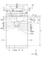
図1は、第1実施形態に係るシート包装体を示す図である。図2は、図1のシート包装体に収容されたシート積層体を示す図である。図3は、図1のシート包装体を天面側から見た図である。図4は、図1のシート包装体を底面側から見た図である。図5は、図1のシート包装体を正面側から見た図である。図6は、図1のシート包装体を左側面側から見た図である。図7は、図1のシート包装体を右側面側から見た図である。 FIG. 1 is a diagram showing a sheet package according to the first embodiment. FIG. 2 is a diagram showing a sheet stack housed in the sheet package of FIG. 1. FIG. 3 is a diagram of the sheet package shown in FIG. 1 viewed from the top side. FIG. 4 is a diagram of the sheet package shown in FIG. 1 viewed from the bottom side. FIG. 5 is a diagram of the sheet package shown in FIG. 1 viewed from the front side. FIG. 6 is a view of the sheet package of FIG. 1 viewed from the left side. FIG. 7 is a view of the sheet package shown in FIG. 1 viewed from the right side.
第1実施形態に係るシート包装体100は、図1に示すように、包装袋10、取出口20を有する。シート包装体100は、実施形態に係るシート包装体の一例である。包装袋10、取出口20は、実施形態に係るシート包装体を構成する包装袋、取出口の一例である。 The
包装袋10は、図1に示すように、積層された複数枚(または複数組)のシートS(以下、シート積層体SLという)が収容される。シート積層体SLは、シートSの積層方向(LD方向)が高さ方向(Z方向)となるように、包装袋10に収容されている(図1、図2)。シート積層体SLは、包装袋10に形成される取出口20(開口OP)を通してシートSが1枚ずつ(または1組ずつ)引き出せるようになっている(図12)。 As shown in FIG. 1, the
シート積層体SLの形態は、特に限定されず、例えば、シートSの折目FがつまめるようにシートSが折りたたまれた状態で積層されたもの(図2)、各シートSが折り込まれた状態で互い違いに積層されたもの(いわゆるポップアップ式のシート積層体)、複数枚のシートSが単に積層されたもの等を採用することができる。 The form of the sheet laminate SL is not particularly limited, and for example, the sheets S may be stacked in a folded state so that the folds F of the sheets S can be pinched together (Fig. 2), or a state in which each sheet S is folded. It is possible to adopt a structure in which sheets S are stacked alternately (a so-called pop-up sheet stack), a structure in which a plurality of sheets S are simply stacked on top of each other, etc.
また、シート積層体SLの寸法は、シート包装体100の長手方向(Y方向)の長さを80mm以上195mm以下、シート包装体100の長手方向(Y方向)に直交する短手方向(X方向)の幅を50mm以上145mm以下、高さ方向(Z方向)の高さを5mm以上80mm以下とすることができる(図2)。 In addition, the dimensions of the sheet laminate SL are such that the length of the
なお、シート積層体SLの態様は、特に限定されない。例えば、シート積層体SLとして、1枚(または1組)のシートが、Z折りにされ、上下の折り返し縁部が各々半分に折り返され、さらに長手方向の中央で2つ折りに折り畳まれた状態で積層されたものを用いることができる。 Note that the form of the sheet laminate SL is not particularly limited. For example, as the sheet laminate SL, one sheet (or one set) is Z-folded, the upper and lower folded edges are each folded in half, and the sheet is further folded in half at the center in the longitudinal direction. A laminated structure can be used.
シート積層体SLを構成するシートSの態様は、特に限定されず、例えば、ティシューペーパー、トイレットペーパー、キッチンペーパー、ペーパータオル等の衛生薄葉紙に適用可能である。これらの衛生薄葉紙には、保湿成分を含んだ衛生薄葉紙(例えば、ローションティシュー等)も含まれる。さらに、これらの衛生薄葉紙には、アルコールや次亜塩素酸ナトリウム等の水溶液、芳香剤等の香料、消臭剤等の薬剤等が含まれていてもよい。The form of the sheets S constituting the sheet laminate SL is not particularly limited, and can be applied to sanitary thin papers such as tissue paper, toilet paper, kitchen paper, paper towels, etc. These sanitary thin papers also include sanitary thin papers containing moisturizing ingredients (e.g., lotion tissue, etc.). Furthermore, these sanitary thin papers may contain aqueous solutions of alcohol or sodium hypochlorite, fragrances such as air fresheners, chemicals such as deodorants, etc.
また、シートSの用途は、特に限定されず、産業用、家庭用、携帯用のいずれも適用できる。なお、本実施形態におけるシートとしては、これらの中でも、家庭用、携帯用のローションティシューが好適に用いられる。 Further, the use of the sheet S is not particularly limited, and can be applied to any of industrial, household, and portable uses. Note that among these sheets, household and portable lotion tissues are preferably used as the sheet in this embodiment.
シートSのプライ数は、特に限定されず、1プライ以上にすることができ、好ましくは1プライであり、より好ましくは2プライ(2枚重ね)である。また、シートSの形状は、特に限定されず、例えば、2プライのシートが折り畳まれた状態の形状が平面視で四角形(長方形、正方形等)であることが好ましい。 The number of plies of the sheet S is not particularly limited, and can be one or more, preferably one ply, and more preferably two plies (two sheets stacked). Further, the shape of the sheet S is not particularly limited, and for example, it is preferable that the shape of the two-ply sheet in a folded state is a quadrilateral (rectangle, square, etc.) in plan view.
シートSの材質は、特に限定されず、例えば、紙、不織布または布等のシートを用いることができ、好ましくは紙製のシート(以下、紙シートという)である。なお、シートSが紙シートの場合、パルプを主原料とする原紙が用いられる。パルプ組成は、紙シートにおける公知の組成を用いることができる。例えば、パルプの配合割合を、50質量%以上、好ましくは90質量%以上、より好ましくは100質量%とすることができる。 The material of the sheet S is not particularly limited, and for example, a sheet of paper, nonwoven fabric, or cloth can be used, and preferably a sheet made of paper (hereinafter referred to as a paper sheet). Note that when the sheet S is a paper sheet, a base paper whose main raw material is pulp is used. As the pulp composition, a known composition for paper sheets can be used. For example, the blending ratio of pulp can be 50% by mass or more, preferably 90% by mass or more, and more preferably 100% by mass.
また、シートS(紙シート)におけるパルプ組成は、特に限定されない。例えば、NBKP(針葉樹クラフトパルプ)やNUKP(針葉樹未晒しパルプ)などの針葉樹パルプと、LBKP(広葉樹クラフトパルプ)やLUKP(広葉樹未晒しパルプ)などの広葉樹パルプとを、任意の比率で使用することができる。なお、針葉樹パルプと広葉樹パルプの比は、限定されず、好ましくは10:90~80:20であり、より好ましくは広葉樹パルプに対して針葉樹パルプの比率がより多いパルプ組成である。また、シートS(紙シート)に含まれるパルプには、古紙パルプを用いてもよい。 Further, the pulp composition in the sheet S (paper sheet) is not particularly limited. For example, softwood pulp such as NBKP (softwood kraft pulp) or NUKP (softwood unbleached pulp) and hardwood pulp such as LBKP (hardwood kraft pulp) or LUKP (hardwood unbleached pulp) can be used in any ratio. I can do it. Note that the ratio of softwood pulp to hardwood pulp is not limited, and is preferably 10:90 to 80:20, more preferably a pulp composition in which the ratio of softwood pulp to hardwood pulp is higher. Furthermore, waste paper pulp may be used as the pulp contained in the sheet S (paper sheet).
シートSの坪量は、特に限定されないが、プライ数に応じて、紙の場合は5g/m2以上80g/m2以下、不織布の場合は20g/m2以上100g/m2以下のものが望ましい。なお、坪量は、JIS P 8124の規定に準拠して測定することができる。 The basis weight of the sheet S is not particularly limited, but depending on the number of plies, it is 5 g/m2 or more and 80 g/m2 or less in the case of paper, and 20 g/m2 or more and 100 g/m2 or less in the case of nonwoven fabric. desirable. Note that the basis weight can be measured in accordance with the regulations of JIS P 8124.
また、シートS(紙シート)の厚みは、特に限定されず、JIS P 8111(1998)の環境下で測定された紙厚を採用することができる。例えば、シートS(紙シートの紙厚は、2プライあたり、50μm以上500μm以下にすることができ、好ましくは60μm以上330μm以下、より好ましくは100μm以上200μm以下である。 Further, the thickness of the sheet S (paper sheet) is not particularly limited, and a paper thickness measured under the environment of JIS P 8111 (1998) can be adopted. For example, the paper thickness of the sheet S (paper sheet can be 50 μm or more and 500 μm or less per 2 plies, preferably 60 μm or more and 330 μm or less, and more preferably 100 μm or more and 200 μm or less).
また、シートS(紙シート)には、エンボス加工が施されていてもよい。このようなエンボス加工は、公知のエンボス付与方法により実施することができる。 Further, the sheet S (paper sheet) may be embossed. Such embossing can be performed by a known embossing method.
包装袋10の包装形態は、特に限定されない。例えば、ガセット状に折り込まれた筒状の可撓性フィルムの両端部またはいずれか一方の端部をシール(封止)する包装(ピロー包装)、筒状の可撓性フィルムの両端部を折り畳んでシール(封止)する包装(キャラメル包装)、熱収縮性の樹脂フィルムを加熱して被包装体に密着させる包装(シュリンク包装)、またはこれらを組み合わせた包装等を採用することができる。 The packaging form of the
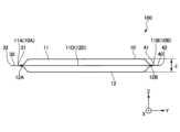
本実施形態では、シートS(シート積層体SL)がピロー包装されている。なお、ピロー包装は、三つ折りされた筒状のフィルム、あるいは、ガセット状に折り込まれた筒状の可撓性フィルムの両端部またはいずれか一方の端部をシール(封止)する包装形態である。具体的には、シート包装体100において、包装袋10の第1方向(X方向)と交差する第2方向(Y方向)の両端部10A、10Bに、シート積層体SLがピロー包装されるようにシール部30、40がそれぞれ形成されている(図1、図3、図4)。 In this embodiment, the sheet S (sheet laminate SL) is pillow-wrapped. Pillow packaging is a packaging form in which both ends or one end of a cylindrical film folded into three or a gusseted flexible cylindrical film are sealed. be. Specifically, in the
ここで、第1方向(X方向)は、包装袋10の天面11上の所定の一方向に沿う方向(X方向)を示す。また、第1方向(X方向)と交差する第2方向(Y方向)は、包装袋10の天面11と同一平面上で第1方向(X方向)と直交する方向または筋かいに交わる方向に沿う方向(Y方向)を示す(図3)。 Here, the first direction (X direction) indicates a direction (X direction) along a predetermined direction on the
シール部30は、第1方向(X方向)に延びる内端31と外端32を有し、内端31で包装袋10の端部10Aを封止する。また、シール部40は、第1方向(X方向)に延びる内端41と外端42を有し、内端41で包装袋10の端部10Bを封止する(図3~図7)。 The
なお、包装袋10の材質が後述する樹脂等のフィルムの場合、第1方向(X方向)は、樹脂成形において樹脂を流す方向(フィルムの延伸方向または流れ方向)であることが好ましい。また、第2方向(Y方向)は、延伸方向または流れ方向と直交する方向であることが好ましい。 In addition, when the material of the
包装袋10の材質は、特に限定されず、例えば、ポリエチレン(PE)、ポリプロピレン(PP)、ポリエチレンテレフタレート(PET)、ポリスチレン(PS)、ポリ塩化ビニル(PVC)、エチレン-酢酸ビニル共重合体(EVA)、ポリアミド(PA)等の樹脂を用いることができる。 The material of the
なお、これらの樹脂の中でも、柔軟で取扱い性に優れ、シール性が高く、安価であること等の観点から、ポリエチレン、ポリプロピレン、ポリエチレンテレフタレート等が好ましい。また、無臭であり、耐水性・耐薬品性に優れ、低コストで大量生産が可能である観点から、ポリエチレンが好ましい。ポリエチレンとしては、高密度ポリエチレン、低密度ポリエチレン等を用いることができる。また、堅牢であり、成形しやすく、印刷時の発色がよく、また光沢を付与できること等の観点からは、ポリプロピレンが好ましい。 Among these resins, polyethylene, polypropylene, polyethylene terephthalate, and the like are preferred because they are flexible, have excellent handling properties, have high sealing properties, and are inexpensive. Further, polyethylene is preferred because it is odorless, has excellent water resistance and chemical resistance, and can be mass-produced at low cost. As the polyethylene, high density polyethylene, low density polyethylene, etc. can be used. Further, polypropylene is preferable from the viewpoints of being strong, easy to mold, showing good color development during printing, and being able to impart gloss.
包装袋10の形態は、特に限定されず、上述の樹脂が単層で形成された単層フィルム、上述の樹脂を積層したラミネートフィルム、または、上述の2種類以上の樹脂の混合物で形成された混合フィルムであってもよい。 The form of the
包装袋10の厚みは、特に限定されず、好ましくは10μm以上100μm以下、より好ましくは15μm以上70μm以下である。包装袋10の厚みを10μm以上とすることで、シートSが収容される包装袋10としての十分な強度を確保することができる。また、包装袋10の厚みを100μm以下とすることで、包装袋10の柔軟性及び軽量性を確保できるとともに、コストが抑えられる。The thickness of the
なお、包装袋10を形成する材質は、上述した可撓性フィルム等の樹脂材料に限定されず、紙材料(クラフト紙等)を用いてもよい。また、包装袋10を形成する材質には、生分解性材料(生分解性プラスチック、生分解性紙等)、バイオマス材料(バイオマスフィルム等の再生可能な生物由来の有機性資源で化石資源を除いたもの)を用いることができる。The material from which the
また、包装袋10は、天面11、底面12を有する。シート包装体100では、天面11と底面12が上下方向(Z方向)に対向する(図1、図3~図7)。なお、天面11は、本実施形態に係るシート包装体を構成する包装袋の天面の一例である。 Furthermore, the
天面11は、第1方向(X方向)に延びる端縁11A、11Bと第2方向(Y方向)に延びる端縁11C、11Dを有する。底面12は、第1方向(X方向)に延びる端縁12A、12Bと第2方向(Y方向)に延びる端縁12C、12Dを有する(図3、図4)。 The
天面11の端縁11A及び底面12の端縁12Aには、シール部30が形成されている。天面11の端縁11B及び底面12の端縁12Bには、シール部40が形成されている(図3~図7)。すなわち、包装袋10では、天面11の端縁11Aと底面12の端縁12Aとが、シール部30を介して一体化され、天面11の端縁11Bと底面12の端縁12Bとが、シール部40を介して一体化されている(図5~図7)。 A
包装袋10の寸法は、シート包装体100の長手方向(Y方向)の長さLを80mm以上200mm以下、シート包装体100の長手方向(Y方向)に直交する短手方向(X方向)の幅Wを50mm以上150mm以下、高さ方向(Z方向)の高さJを5mm以上85mm以下とすることができる(図3、図5)。なお、この包装袋10の寸法は、包装袋10にシート積層体SLが収容された状態での寸法を示す(図1、図2、図12~図14)。 The dimensions of the
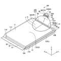
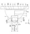
取出口20は、天面11に形成されて、シートSが取り出される(図9)。取出口20は、包装袋10の天面11の一部BLが開裂すると天面11に開口する(図1、図12)。本実施形態では、取出口20が天面11に形成された開裂用切目線CL(例えば、ミシン目)で形成され、この開裂用切目線CLが開裂すると、包装袋10の天面11に開口OPが形成され、この開口OPが取出口20となる(図1、図3、図9)。 The
なお、開裂用切目線CLは、カットC1とタイT1(2つのカットC1間のカットされていない部分)が交互に配置され、タイT1が破断すると両隣のカットC1が連続したカットになる切目線である(図1、図3)。なお、開裂用切目線CLにおいて、カットC1の長さ、及びタイT1の長さは、任意である。 Note that the cleavage cut line CL is a cut line where cuts C1 and ties T1 (uncut portions between two cuts C1) are arranged alternately, and when a tie T1 is broken, the cuts C1 on both sides become continuous cuts. (Figures 1 and 3). In addition, in the cleavage score line CL, the length of the cut C1 and the length of the tie T1 are arbitrary.
開裂用切目線CLにおいて、各カットC1の長さは、0.8mm以上9.0mm以下にすることができ、好ましくは1.5mm以上8.0mm以下、より好ましくは2.5mm以上7.0mm以下である。また、各タイT1の長さは、0.3mm以上5.0mm以下にすることができ、好ましくは0.4mm以上2.0mm以下、より好ましくは0.5mm以上1.5mm以下である。In the tearing cut line CL, the length of each cut C1 can be 0.8 mm or more and 9.0 mm or less, preferably 1.5 mm or more and 8.0 mm or less, and more preferably 2.5 mm or more and 7.0 mm or less. Also, the length of each tie T1 can be 0.3 mm or more and 5.0 mm or less, preferably 0.4 mm or more and 2.0 mm or less, and more preferably 0.5 mm or more and 1.5 mm or less.
取出口20の形状は、任意である。本実施形態では、取出口20の形状が、平面視で半楕円形状となっている。本実施形態では、取出口20の形状は、蓋体50の第1端縁51と反対側の第2端縁52が、第1端縁51から離れる側に向かって凸となっている。The shape of the
ここで、蓋体50の第1端縁51と反対側の第2端縁52は、蓋体50において天面11に接続された固定端(第1端縁51)に対向する天面11に接続されない自由端(第2端縁52)を示す。また、第2端縁52が第1端縁51から離れる側に向かって凸となるとは、蓋体50において天面11に接続されない自由端(第2端縁52)が天面11に接続された固定端(第1端縁51)の両末端20A、20Bに接続し、固定端(第1端縁51)から離れる方向に平面視でせり出す(凸部20Cを構成する)ことを示す(図3、図8)。 Here, the
具体的には、取出口20は、天面の端縁11A側の末端20Aから末端20Bに延び、天面の端縁11Aから中央部11Eに向かって凸となる(凸部20Cを形成する)ように形成されている(図1、図3、図8)。ここで、天面11の中央部11Eは、天面11の中心(図心)Gを含み、天面11全体の10分の1から5分の1程度の広さの領域を示す(図3)。これにより、取出口20は、第1方向(X方向)の端縁11B側に形成されている。 Specifically, the
なお、第1方向(X方向)における取出口20の間隔L2は、包装袋10の長手方向(Y方向)の長さL1に対して、15%以上60%以下であり、好ましくは20%以上55%以下、より好ましくは25%以上50%以下である。また、第2方向(Y方向)における取出口20の間隔W2は、包装袋10の幅方向(Y方向)の幅W1に対して、50%以上90%以下であり、好ましくは60%以上85%以下、より好ましくは70%以上80%以下である(図3)。 Note that the interval L2 between the
本実施形態のシート包装体100は、さらに蓋体50を有する。蓋体50は、開裂した天面11の一部BLで形成され、取出口20を再封可能に閉口する。ここで、取出口20を再封可能に閉口するとは、開口した取出口20(開口OP)を蓋体50が覆うことを示す(図1、図3、図12、図14)。 The
蓋体50は、第1端縁51が天面11に接続されている。本実施形態では、蓋体50の第1端縁51が、シール部40側に構成されている(図3)。天面11に接続される蓋体50の第1端縁5)は、取出口20(OP)が開口した状態で天面11に接続された蓋体50の固定端を構成する。なお、固定端を構成する蓋体50の第1端縁51は、取出口20を開口または閉口する際の基端となる取出口20の端縁20Dに対応する(図3、図8)。なお、取出口20の端縁20Dは、シール部40の内端41に構成され、蓋体50の第1端縁51(取出口20の端縁20D)は、シール部40の内端41に固定されている(図3、図8、図12~図14)。The
本実施形態のシート包装体100では、蓋体50に、第1端縁51に沿って延びる第1押圧加工部60が設けられている。具体的には、天面11に接続する蓋体50の第1端縁51の近傍51A(第1端縁51寄り)に第1押圧加工部60が配置されている。第1押圧加工部60は、蓋体50の第1端縁51と平行に配置されている(図1、図3、図8)。 In the
なお、押圧加工部は、蓋体50となる天面11の一部BLに型等を押し当てて加圧変形した部分である。このような押圧加工部は、押圧により蓋体50に形成されるため、押圧加工部を形成する作業は容易である(図1、図3、図8)。The pressed portion is a portion that is deformed by pressing a mold or the like against the portion BL of the
第1押圧加工部60は、天面11の第1方向(X方向)と交差する第2方向(Y方向)に延びている。第1押圧加工部60は、シール部40から第1方向(X方向)に離れる間隔L3が約1mmの位置で、第2方向(Y方向)に沿ってシール部40と平行に延びている(図3、図8)。 The first
なお、第1方向(X方向)におけるシール部40と第1押圧加工部60との間隔L3は、本実施形態における距離に限定されない。例えば、シール部40と第1押圧加工部60との間隔L3は、第1方向(X方向)における取出口20の間隔L2に対して、0.5%以上20%以下であり、好ましくは1%以上15%以下、より好ましくは2%以上10%以下である。 Note that the distance L3 between the
なお、第2方向(Y方向)における第1押圧加工部60の長さ(幅W3)は、本実施形態における距離に限定されない。例えば、第1押圧加工部60の長さ(幅W3)は、第2方向(Y方向)における取出口20の間隔(幅W2)に対して、65%以上100%以下であり、好ましくは70%以上100%以下、より好ましくは75%以上100%以下である(図3)。 Note that the length (width W3) of the first pressing
本実施形態では、第1押圧加工部60は、第2方向(Y方向)の長さ(幅W3)が、取出口20の第2方向(Y方向)の幅W2よりも短くなっている。具体的には、第1押圧加工部60の端部61は、天面11の端縁11C側で、蓋体50の第2端縁52から内側に離れて配置されている。また、第1押圧加工部60の端部62は、天面11の端縁11D側で、蓋体50の第2端縁52から内側に離れて配置されている(図1、図3、図8)。 In this embodiment, the length (width W3) of the first pressing
なお、第1押圧加工部60を設ける際の位置決めを容易にする観点から、第1押圧加工部60の第2方向(Y方向)の長さ(幅W3)が取出口20の第2方向(Y方向)の幅W2より長くなるように、第1押圧加工部60を設けてもよい。 In addition, from the viewpoint of facilitating positioning when providing the first
本実施形態では、天面11に接続する蓋体50の第1端縁51に沿って延びる第1押圧加工部60が蓋体50に形成されていることで、取出口20を開封(または開口)する方向(Y方向)に蓋体50を展開したときに、展開した蓋体50が取出口20(OP)を再封(または閉口)する元の状態に戻ろうとする蓋体50の動きを遅くする(蓋体50の閉口動作を遅延させる)ことができる。 In this embodiment, the first press-processed
これにより、取出口20(OP)からシートSを取り出す際に、展開された蓋体50が取出口20(OP)から離れた状態を維持することができる(図12、図13)。そのため、本実施形態によれば、取出口からのシートの取り出し易い(取出性が良好である)。 Thereby, when taking out the sheet S from the take-out port 20 (OP), the opened
なお、蓋体50が元の状態に戻ろうとする動きは、蓋体50に加わった外力により蓋体50の内部に生じる弾性応力(以下、応力という)による蓋体50の動きであると考えられる。そして、蓋体50の内部に生じた弾性応力分布が押圧加工部により不連続ないし部分的に緩和されること(以下、応力緩和という)が、蓋体50の閉口動作を遅延させる理由の一つと考えられる。 The movement of the
なお、シートの取出性は、図13に示すように、シート包装体100における蓋体50の角度として、包装袋10の天面11を開裂し、取出口20を開口する方向に蓋体を約180°展開し、約3秒放置したときの、蓋体50の角度θを測定することで評価することができる。角度θは、展開された蓋体50の天面11に対する角度とする(図13)。角度θが90°以上のとき、展開された蓋体50が取出口20(OP)から離れた状態が維持され取出性が良好であると判断できる。 Note that, as shown in FIG. 13, the ease of taking out the sheet is determined by determining the angle of the
このような構成により、本実施形態では、取出口20(OP)を覆う蓋体50が設けられている場合でも、取出口20(OP)からシートSを取り出す際に、蓋体50が邪魔になりにくい(図12、図13)。そのため、本実施形態によれば、シートSの取り出しが容易なシート包装体100を提供することができる。 With such a configuration, in this embodiment, even when the
また、本実施形態では、取出口20(OP)を再封可能に閉口する蓋体50が、天面11に接続された蓋体50の第1端縁51に沿って延びる第1押圧加工部60を有することで、取出口20を開封する際に、第1押圧加工部60に沿って蓋体50が折れ曲がりやすくなる。これにより、天面11に接続される蓋体50の端縁(第1端縁51)の近傍51Aを基端として蓋体50が展開され、取出口20が開口された状態が維持されやすくなるため、取出口20(OP)からのシートSの取り出しが容易になる(図12、図13)。 Further, in the present embodiment, the
さらに、本実施形態では、開裂した天面11の一部BLが取出口20(OP)を再封可能に閉口する蓋体50を構成することで、取出口20(OP)を閉口することができるため、取出口20から包装袋10内にゴミや埃等(以下、塵埃という)が入りにくくなる。これにより、本実施形態では、シート包装体100を衛生的に使用することができる(図14)。 Furthermore, in the present embodiment, the opening 20 (OP) can be closed by the part BL of the opened
さらに、本実施形態では、開裂した天面11の一部BLが取出口20(OP)を再封可能に閉口する蓋体50となり、蓋体50の第1端縁51が天面11に接続されていることで、開裂した天面11の一部BLを構成する蓋体50が、包装袋10から切り離されずに天面11に接続した小片BLとなる。そのため、本実施形態では、取出口20の開封(または開口)時に断片(包装袋10から切り離された切れ端等)が発生するのを防ぐことができる(図12~図14)。 Furthermore, in this embodiment, the part BL of the
なお、本実施形態では、蓋体50の第1押圧加工部60が蓋体50のシール部40側に設けられていることで、天面11に接続された蓋体50の第1端縁51の近傍51Aが蓋体50の第1押圧加工部60となる。蓋体50のシール部40側の第1端縁51の近傍51Aは、取出口20を開口するために蓋体50を展開したときに応力が生じやすい部分であるため、この部分に蓋体50の第1押圧加工部60を設けることで、蓋体50の応力が緩和されやすくなる。そのため、本実施形態によれば、蓋体50の閉口動作を遅延させる機能を高めることができる(図12、図13)。 In addition, in this embodiment, the first
また、本実施形態では、取出口20が天面11の第1方向(X方向)の一方の端縁11B側に形成されているため、取出口20が天面11全体に形成されることはない。そのため、取出口20が開口した後も包装袋10の形状が保たれやすく、包装袋10内でシートS(シート積層体SL)の収容状態が乱れにくい。そのため、本実施形態によれば、シート包装体100を最後まできれいに使用することができる(図12~図13)。 Furthermore, in this embodiment, since the
また、本実施形態では、取出口20を天面11の第1方向(X方向)の一方の端縁11B側に形成することで、取出口20を天面11のシール部40側に開口させることができる。これにより、取出口20からシートSを取り出す際に、シートSを天面11側に引き出すことができ、また第1方向(X方向)に沿ってシール部40側にも引き出すこともできる。そのため、本実施形態によれば、使い勝手がよいシート包装体100を提供することができる(図12、図13)。 Furthermore, in the present embodiment, the
本実施形態では、蓋体50の第1押圧加工部60が天面11の第1方向(X方向)と交差する第2方向(Y方向)に延びることで、天面11に接続された蓋体50の第1端縁51に沿って第1押圧加工部60を設けることができる。これにより、本実施形態では、蓋体50の応力がさらに緩和されやすくなり、蓋体50の閉口動作を遅延させる機能をさらに高めることができる(図9、図10)。In this embodiment, the first pressed
本実施形態では、上述のように、蓋体50の第1端縁51と反対側の第2端縁52が第1端縁51から離れる側に向かって凸となる(凸部20Cを構成する)ことで、第2端縁52が第1端縁51から離れる方向にせり出すトリガー(凸部20C)を構成することができる。このようにせり出すトリガー(凸部20C)は、指先でつまみやすいため、取出口20の開封が容易になる(図1、図3、図8、図12)。 In this embodiment, as described above, the
また、本実施形態では、蓋体50の第2端縁52が第1端縁51から離れる方向にせり出すトリガー(凸部20C)を構成することで、取出口20の開封時(または開口時)に蓋体50の第2端縁52を簡単につまむことができるため、包装袋10の天面11を押え付けずに取出口20を開封することができる。そのため、本実施形態では、取出口20の開封時に包装袋10に収容されたシートSが破れるのを防ぐことができる(図1、図3、図8、図12)。 Furthermore, in this embodiment, by configuring a trigger (
本実施形態に係るシート包装体100では、蓋体50に、さらに第2押圧加工部70が形成されている。第2押圧加工部70は、第1押圧加工部60が延びる方向(X方向)と交差する方向(Y方向)に延びる。ここで、交差する方向とは、直交する方向を含む筋かいとなる方向を示す。 In the
本実施形態では、第2押圧加工部70は、第1押圧加工部60と直交する方向に延びる。そして、第2押圧加工部70の端部71は、蓋体50の第1端縁51側(第1押圧加工部60の近傍)に配置され、第2押圧加工部70の端部72は、蓋体50の第2端縁52側(第1押圧加工部60から離れた位置)に配置されている(図1、図3、図8)。 In this embodiment, the second
なお、第1方向(X方向)における第2押圧加工部70の長さL4は、本実施形態における距離に限定されない。例えば、第2押圧加工部70の長さL4は、第1方向(X方向)における取出口20の間隔L2)に対して、30%以上100%以下であり、好ましくは50%以上100%以下、より好ましくは60%以上100%以下である(図3)。なお、本実施形態では、第2押圧加工部70が、第1押圧加工部60に接続していないが、第2押圧加工部70は第1押圧加工部60に接続していてもよい。 Note that the length L4 of the second
本実施形態では、蓋体50に第1押圧加工部60が延びる方向(X方向)と交差する方向(Y方向)に延びる第2押圧加工部70が蓋体50に形成されることで、蓋体50の開封時(または開口時)に蓋体50の形状が維持されるため、シートSの取り出しが容易になる(図1、図3、図8、図12、図13)。また、蓋体50の形状が維持されることで、取出口20(OP)の再封時(または閉口時)に、取出口20(OP)と蓋体50の間に生じる隙間を小さくすることができるので、再封時(または閉口時)における包装袋10内への塵埃の進入を防ぐことができる(図14)。 In the present embodiment, the second
本実施形態に係るシート包装体100では、蓋体50の第1端縁51と反対側の第2端縁52側に、天面11に着脱可能に接着する接着用シール80が固定されている(図1、図3)。ここで、接着用シール80は、蓋体50に固定された状態で蓋体50の外側の天面11に接着するシールである。 In the
接着用シール80は、固定部81、粘着部82、及び自由端部83を有する。接着用シール80において、固定部81は蓋体50の端縁52に固定され、粘着部82は天面11に剥離可能に接着し、自由端部83は蓋体50に固定されない(図1、図3、図8)。なお、天面11に着脱可能に接着するとは、粘着部82が、天面11に接着した状態から剥離することができ、且つ剥離した状態から再度天面11に接着することを示す。 The
接着用シール80の態様は、限定されず、例えば、基材(図示せず)に、接着剤が塗布された固定部81と、固定部81より接着力が弱い接着剤が塗布された粘着部82と、これらの接着剤がいずれも塗布されない自由端部83が形成されたものを用いることができる。 The form of the
なお、固定部81と粘着部82の接着剤には、同じ接着力を有する接着剤を用いてもよい。また、自由端部83には、固定部81と粘着部82と同じ接着剤を一旦塗布した上で、その上からニスを塗布して接着性を失わせてもよく、また接着剤を最初から塗布しない状態で構成してもよい。The adhesive for the fixed
なお、基材の材質は、限定されないが、上述の包装袋10に用いられる可撓性フィルム等の樹脂材料、紙材料、生分解性材料、バイオマス材料等を用いることができる。また、基材の形態は、限定されず、上述の包装袋10に用いられる単層フィルム、ラミネートフィルム、混合フィルムを用いることができる。さらに、基材の厚みは、上述の包装袋10に用いられる可撓性フィルム厚みを採用することができる。 Note that the material of the base material is not limited, but resin materials such as flexible films used in the above-mentioned
また、固定部81の接着剤の材質は、限定されないが、粘着力が2N/25mm以上6N/25mm以下の接着剤で構成することが好ましい。また、粘着部82の接着剤の材質は、限定されないが、粘着力が2N/25mm以上6N/25mm以下となる材質であることが好ましい。ここで、粘着力とは、JIS Z0237を参考にした粘着力試験法により測定した引きはがし抵抗値を示す。The adhesive material of the fixing
本実施形態のシート包装体100では、蓋体50の第1端縁51と反対側の第2端縁52側に、天面11に着脱可能に接着する接着用シール80が固定され、第2押圧加工部70の第2端縁52側の端部72が、接着用シール80に覆われていない。 In the
ここで、第2押圧加工部70の第2端縁52側の端部72は、蓋体50の第1端縁51側に位置する第2押圧加工部70の端部71と反対側に位置する第2押圧加工部70の端部72を示す。また、第2押圧加工部70の第2端縁52側の端部72が、接着用シール80に覆われていないとは、接着用シール80が第2押圧加工部70に被らないように配置されていることを示す。 Here, the
本実施形態では、上述のように、蓋体50の第1端縁51と反対側の第2端縁52に接着用シール80が設けられていることで、接着用シール80が天面11の取出口20を開口するためのトリガーTGを構成することができる。そして、接着用シール80を天面11から剥がすと、天面11に取出口20が開裂し、開裂した天面11の一部BLは蓋体50を構成する。このような構成により、包装袋10の天面11を押え付けずに取出口20を開封することができる。そのため、本実施形態では、取出口20の開封時にシートSが破れるのを防ぐことができる(図1、図3、図8、図12、図13)。 In this embodiment, as described above, the
また、本実施形態では、蓋体50にこのような接着用シール80が設けられていることで、取出口20(OP)を再封(または閉口)した状態で接着用シール80を介して蓋体50を天面11に接着することができる。これにより、蓋体50による取出口20(OP)の再封(または閉口)が容易である。また、このような構成では、取出口20(OP)を閉口した状態で、包装袋10の形状が維持されやすく、包装袋10内でシートS(シート積層体SL)の収容状態が乱れにくい。また、蓋体50を再封(または閉口)した状態が維持されるため、再封(または閉口)した取出口20(OP)からの包装袋10内に塵埃の進入を防ぐことができる(図12、図14)。 Further, in this embodiment, since such an
なお、本実施形態では、蓋体50にこのような接着用シール80を設けることで、取出口20(OP)からシートSを取り出す際に、接着用シール80にシートSが貼り付くおそれがある。しかしながら、本実施形態では、上述のように、展開した蓋体50が取出口20(OP)を閉口する元の状態に戻ろうとする蓋体50の動きを遅くすることができるので、蓋体50が邪魔になりにくい。そのため、本実施形態では、蓋体50に接着用シール80を設けた場合でも、接着用シール80にシートSが貼り付きにくい(図12、図13)。 In addition, in this embodiment, by providing such an
本実施形態では、上述のように、第2押圧加工部70の第2端縁52側の端部72が接着用シール80に覆われていないことで、接着用シール80の固定部81と蓋体50の第2端縁52との固着力が低下しにくく、取出口20の開閉時に蓋体50から接着用シール80が剥がれるのを抑制することができる。 In this embodiment, as described above, since the
なお、本実施形態では、第2押圧加工部70の第2端縁52側の端部72が接着用シール80で覆われないようにするために、第2押圧加工部70を短くしなければならず、その分だけ取出口20の開口時における蓋体50の形状の維持がしにくくなるおそれがある。しかしながら、本実施形態では、取出口20の開封後(または開口後)に天面11に接続されない自由端となる変形しやすい蓋体50の第2端縁52が接着用シール80で固定される。そのため、本実施形態では、取出口20の開封後(または開口後)も、蓋体50に形成された第2押圧加工部70と蓋体50に固定された接着用シール80の固定部81とで相乗的に蓋体50の形状を維持することができる(図1、図3、図8、図16、図17)。 In addition, in this embodiment, in order to prevent the
本実施形態のシート包装体100は、第2端縁52の一部52Aが、連続する切目線で構成されている。そして、第2端縁52の一部52Aが、接着用シール80に覆われている。本明細書において、第2端縁52の一部52Aが、連続する切目線で構成されているとは、蓋体の第2端縁52の一部52Aが予めカットされていることを示す。第2端縁52の一部52Aが接着用シール80で覆われるとは、第2端縁52の一部52Aに沿って接着用シール80が蓋体に固定されていることを示す。 In the
具体的には、取出口20を構成する開裂用切目線CLの一部が、蓋体50の第2端縁52の一部52Aに対応する部分で、カットC2とタイT2(1つのカットC2の両端に並ぶカットされていない部分)が交互に予め配置され、蓋体50の第2端縁52の一部52AがこのカットC2に対応することを示す(図8)。そして、カットC2で構成された第2端縁52の一部52Aが接着用シール80で覆われている。 Specifically, a part of the tearing line CL constituting the
なお、蓋体50の第2端縁52の一部52Aに対応する開裂用切目線CLの一部において、カットC2の長さ、及びタイT2の長さは、任意である。例えば、カットC2の長さは、10mm以上30mm以下にすることができ、好ましくは13mm以上27mm以下、より好ましくは16mm以上25mm以下である。また、各タイT2の長さは、0.3mm以上5.0mm以下にすることができ、好ましくは0.4mm以上2.0mm以下、より好ましくは0.5mm以上1.5mm以下である。 Note that the length of the cut C2 and the length of the tie T2 are arbitrary in a part of the tearing score line CL corresponding to the
また、本実施形態では、第2端縁52の一部52Aの第1方向(X方向)の間隔W5が、接着用シール80の第1方向(X方向)の幅W4よりも短くなっている(図8)。接着用シール80の第1方向(X方向)の幅W4は、接着用シール80の第1方向(X方向)に広がる範囲を示す。第2端縁52の一部52Aの第1方向(X方向)の間隔W5は、第2端縁52の一部52Aを構成する第2端縁52の一部52Aの第1方向(X方向)に沿う一方の末端52Bから他方の末端52Cまでの距離W5を示す。なお、第2端縁52の一部52Aの第1方向(X方向)の間隔W5は、取出口20を構成する開裂用切目線CLの一部のカットC2の長さに対応する。 Further, in this embodiment, the interval W5 of the
なお、第2端縁52の一部52Aの第1方向(X方向)の間隔W5は、接着用シール80の第1方向(X方向)の幅W4に対して、75%以上99%以下であり、好ましくは80%以上95%以下、より好ましくは85%以上90%以下である(図8)。本実施形態では、例えば、接着用シール80の第1方向(X方向)の幅W4は約25mmであり、第2端縁52の一部52Aの第1方向(X方向)の間隔W5は約22mmである。The spacing W5 in the first direction (X direction) of the
本実施形態では、蓋体50の第2端縁52の一部52Aを連続する切目線で構成することで、指が第2端縁52の一部52Aに掛かりやすくなる。また、第2端縁52の一部52Aの周辺は、蓋体50の中でも変形しやすい部分のひとつであるが、本実施形態では、このような変形しやすい部分が接着用シール80の固定部で固定されるため、蓋体50の変形を防ぐことができる。 In this embodiment, by configuring the
また、上述のように、蓋体50の第2端縁52の一部52Aを連続する切目線で構成することで、該第2端縁52の一部52Aが予めカットされているため、第2端縁52の一部52Aが接着用シール80に覆われていても、取出口の開封時に包装袋の天面の一部が開裂しやすい。そのため、本実施形態では、取出口の開封時に接着用シール80に覆われた第2端縁52の一部52Aの周辺で、包装袋の天面が予期せぬ部分で破れるのを抑制することができる。 Further, as described above, by configuring the
また、本実施形態では、第2端縁52の一部52Aの第1方向(X方向)の間隔W5が、接着用シール80の第1方向(X方向)の幅W4よりも短くなっていることで、取出口20の開封前に取出口20が開口するのを防ぐことができる。 Further, in this embodiment, the interval W5 of the
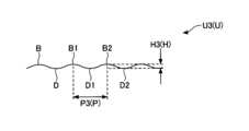
本実施形態のシート包装体100は、自由端部83の端縁83Aが波形Uである。ここで、波形Uは、曲線の凸部Bと凹部Dが繰り返し連続する形状を示す(図9)。In this embodiment, the
本実施形態のシート包装体100は、波形Uの周期Pが、0.1mm以上5mm以下である。ここで、波形Uの周期Pは、波形Uの隣り合う二つの凸部B(凸部B1、B2)間の距離または凹部D(凹部D1、D2)間の距離Pを示す。波形Uの周期Pが0.1mm以上5mm以下であることは、波形Uのスケールが微小であることを示す(図1、図3、図8、図9)。 In the
本実施形態のシート包装体100は、周期Pが、波形Uの波高Hの2倍以上である。ここで、波形Uの波高Hとは、波形Uの凸部Bの頂部から凹部Dの底部までの垂直距離Hを示す(図9)。 In the
実施形態では、接着用シール80の自由端部83の端縁83Aを構成する波形Uとして、例えば、周期P1が波高H1の約5倍である波形U1を採用することができる(図9)。また、波形Uとして、周期P2が波高H2の約10倍である波形U2を採用することができる(図10)。さらに、波形Uとして、周期P3が波高H3の約2倍である波形U3を採用することができる(図11)。 In the embodiment, as the waveform U forming the
波形Uの波高Hは、好ましくは0.03mm以上2mm以下であり、より好ましくは0.05mm以上1.5mm以下であり、さらに好ましくは0.1mm以上0.8mm以下である。なお、波形Uの波高Hが0.03mm以上2mm以下の範囲であることは、波形Uのスケールが微小であることを示す。 The wave height H of the waveform U is preferably 0.03 mm or more and 2 mm or less, more preferably 0.05 mm or more and 1.5 mm or less, and still more preferably 0.1 mm or more and 0.8 mm or less. Note that the fact that the wave height H of the waveform U is in the range of 0.03 mm or more and 2 mm or less indicates that the scale of the waveform U is minute.
本実施形態では、上述のように、接着用シール80が蓋体50に固定されない自由端部83を有することで、接着用シール80がつかみやすくなり、取出口20の開封(開口)及び再封(閉口)(以下、取出口20の開閉という)が容易になる(図1、図3、図8、図12、図14)。 In this embodiment, as described above, since the
また、本実施形態では、上述のように、接着用シール80の自由端部83の端縁83Aを波形Uにすることで、接着用シール80の自由端部83に触れた指先は、自由端部83の端縁83Aの波形Uを構成する曲線の凸部B(凸部B1、B2)だけに接触する(図9)。そのため、接着用シール80の自由端部83をつまんで取出口20を開封(開口)または再封(閉口)する際(以下、取出口20の開閉時という)に、接着用シール80の自由端部83に触れた指先への負担(例えば、指先を痛めたり、指先が傷つくこと等)を抑制することができる(図1、図3、図8~図12、図14)。 In addition, in this embodiment, as described above, by making the
また、本実施形態では、上述のように、接着用シール80の自由端部83の端縁83Aを波形Uにすることで、シート包装体100における取出口20の開閉時に、接着用シール80(自由端部83)が識別しやすくなる。そのため、本実施形態によれば、接着用シール80の自由端部83が指先でつまみやすくなり、取出口20の開閉が容易になる(図1、図3、図8~図12、図14)。 Furthermore, in this embodiment, as described above, by forming the
本実施形態では、上述のように、接着用シール80の自由端部83における端縁83Aの波形Uの周期Pを0.1mm以上5mm以下にすることで、自由端部83の端縁83Aを構成する波形Uの凸部B(凸部B1、B2)または凹部D(凹部D1、D2)の間隔Pが小さくなる。これにより、接着用シール80の自由端部83の端縁83Aに指先の違和感を軽減しながら、該指先への負担をさらに軽減することができる(図1、図3、図8~図12、図14)。 In this embodiment, as described above, by setting the period P of the waveform U of the
また、本実施形態では、接着用シール80における自由端部83の端縁83Aで波形Uの凸部B(凸部B1、B2)または凹部D(凹部D1、D2)の間隔Pが小さくなることで、接着用シール80における自由端部83の端縁83Aを波形Uにすることによるシート包装体100の外観(または見栄え)の低下を抑制することができる(図1、図3、図8~図12、図14)。 Furthermore, in the present embodiment, the interval P between the convex portions B (convex portions B1, B2) or the concave portions D (concave portions D1, D2) of the waveform U at the
本実施形態では、接着用シール80の自由端部83における波形Uの周期Pを波形Uの波高Hの2倍以上にすることで、自由端部83の端縁83Aを構成する波形Uの凸部Bの傾斜がなだらかになる。これにより、接着用シール80において自由端部83の端縁83Aがなめらかになり、自由端部83の端縁83Aに触れる指先の違和感をさらに軽減しながら、該指先への負担をさらに軽減することができる(図1、図3、図8~図12、図14)。 In this embodiment, by making the period P of the waveform U at the
また、本実施形態では、自由端部83の端縁83Aに形成される波形Uの凸部Bの傾斜がなだらかになることで、接着用シール80における自由端部83の端縁83Aを波形Uにすることによるシート包装体100における接着用シール80の外観(または見栄え)の低下を抑制することができる(図1、図3、図8~図12、図14)。 Further, in this embodiment, the slope of the convex portion B of the waveform U formed on the
本実施形態のシート包装体100は、自由端部83に、接着用シール80の幅方向(X方向)に延びる第3押圧加工部90が形成されている。ここで、接着用シール80の幅方向は、シート包装体100における取出口20の開閉時に接着用シール80を着脱する方向(Y方向)と交差する方向(X方向)を示す(図1、図3、図8)。 In the
なお、本実施形態では、第3押圧加工部90の長さW6が、接着用シール80の第1方向(X方向)の幅W4よりも短くなっているが、第3押圧加工部90の長さW6は、接着用シール80の第1方向(X方向)の幅W4と同じにしてもよい。なお、本実施形態では、第3押圧加工部90の長さW6は、第2端縁52の一部52Aの第1方向(X方向)の間隔W5と同じ寸法となっているが、第3押圧加工部90の長さW6は、第2端縁52の一部52Aの間隔W5より長くても、また短くてもよい。 In addition, in this embodiment, the length W6 of the third
本実施形態では、接着用シール80の自由端部83に接着用シール80の幅方向(X方向)に延びる第3押圧加工部90を設けることで、第3押圧加工部90に沿って接着用シール80の自由端部83が折れ曲がりやすくなる。これにより、本実施形態では、接着用シール80の自由端部83がつまみやすくなり、取出口20の開閉が容易になる(図1、図3、図8、図12、図14)。 In this embodiment, by providing the third
図15は、第1実施形態の第1変形例を示す図である。なお、図15において、図1、図3、図8と共通する部分については、説明を省略する。第1実施形態の第1変形例に係るシート包装体100では、蓋体50に、天面11に接続する蓋体50の第1端縁51に沿って延びる第1押圧加工部60が形成され、第2押圧加工部70は形成されていない(図15)。 FIG. 15 is a diagram showing a first modification of the first embodiment. Note that in FIG. 15, descriptions of parts common to FIGS. 1, 3, and 8 will be omitted. In the
第1実施形態の第1変形例では、上述の第1実施形態(図8)と同様に第1押圧加工部60が設けられているため、第2押圧加工部70は形成されていなくても、第1押圧加工部60が設けられることによる効果と同様の効果が得られる。すなわち、第1実施形態の第1変形例によれば、取出口20(OP)からシートSを取り出す際に、展開された蓋体50が取出口20(OP)から離れた状態を維持することができ、取出性が良好なシート包装体を提供することができる(図13、図15)。 In the first modified example of the first embodiment, the first
図16は、第1実施形態の第2変形例を示す図である。なお、図16において、図1、図3、図8と共通する部分については、説明を省略する。第1実施形態の第2変形例に係るシート包装体100では、蓋体50の第1端縁51と反対側の第2端縁52の一部52Aが、第1端縁51側に向かって凸となる(図16)。 FIG. 16 is a diagram showing a second modification of the first embodiment. Note that in FIG. 16, descriptions of parts common to FIGS. 1, 3, and 8 will be omitted. In the
ここで、第2端縁52の一部52Aが第1端縁51側に向かって凸となるとは、蓋体50において天面11に接続されない自由端(第2端縁52)の一部が該自由端(第2端縁52)側から天面11に接続された固定端(第1端縁51)側に向かって平面視で窪む(凹部IAを構成する)ことを示す(図16)。 Here, when the
第1実施形態の第2変形例では、蓋体50の第1端縁51と反対側の第2端縁52の一部52Aが第1端縁51側に向かって凸となる(凹部IAを構成する)ことで、蓋体50の第1端縁51と第2端縁52の間隔L2が短くなる。これにより、蓋体50の面積が小さくなり、取出口20の開封時(または開口時)あるいは再封時(または閉口時)に蓋体50が変形しにくくなる。そのため、取出口20(OP)の再封時(または閉口時)に、取出口20と蓋体50の間に生じる隙間を小さくすることができるので、再封時(または閉口時)に取出口20から包装袋10内に塵埃が進入するのを防ぐことができる(図16)。 In the second modification of the first embodiment, a
また、本実施形態では、蓋体50の第1端縁51と反対側の第2端縁52の一部52Aが第1端縁51側に向かって凸となる(凹部IAを構成する)ことで、第2端縁52の一部52Aが第1端縁51側に窪んだトリガー(凹部IA)を構成することができる。このような窪んだトリガー(凹部IA)は、指先が掛りやすい。そのため、本実施形態では、接着用シール80が設けられていなくても、取出口20の開封(または開口)が容易になる(図16)。 Furthermore, in the present embodiment, a
また、本実施形態では、蓋体50の第2端縁52の一部52Aがこのような窪んだトリガー(凹部IA)を構成することで、取出口20の開封時(または開口時)に蓋体50の第2端縁52を簡単につまむことができる。そのため、包装袋10の天面11を押え付けずに取出口20を開封することができる。これにより、本実施形態では、取出口20の開封時に包装袋10に収容されたシートSが破れるのを防ぐことができる(図16)。 Furthermore, in this embodiment, the
さらに、本実施形態では、蓋体50の第1端縁51と反対側の第2端縁52の一部52Aが第1端縁51側に向かって凸となる(凹部IAを構成する)ことで、開封された取出口20(OP)において第2端縁52に対応する蓋体50の自由端(第2端縁52)が第1端縁51に対応する蓋体50の固定端(第1端縁51)側に湾曲する形状となる。これにより、天面11からシートSが引き出される際に、取出口20の第2端縁52側の端縁(凹部IC)付近で天面11の一部BLが撓みやすくなり、引き出されるシートSに対する摩擦力を緩和することができる。そのため、本実施形態では、シートSを引き出す際に、シートSが破れにくくなる(図16)。 Furthermore, in the present embodiment, a
図17は、第2実施形態に係るシート包装体において取出口とシール部の一部を拡大した図である。なお、図17において、図1、図3、図8と共通する部分については、説明を省略する。第2実施形態のシート包装体400では、取出口20が、天面11の第1方向(X方向)と交差する第2方向(Y方向)の両端縁11C、11Dのうち一方の端縁11C側に形成され、蓋体50は、第2方向(Y方向)のうち一方の端縁11C側の第1端縁51が天面11に接続され、第1押圧加工部60が、蓋体50の第1端縁51側に設けられている(図17)。 FIG. 17 is an enlarged view of a portion of the outlet and the seal portion in the sheet package according to the second embodiment. Note that in FIG. 17, descriptions of parts common to FIGS. 1, 3, and 8 will be omitted. In the
なお、第2実施形態では、包装袋10の材質が樹脂等のフィルムの場合、第1方向(X方向)は、樹脂成形において樹脂を流す方向(フィルムの延伸方向または流れ方向)と直交する方向であることが好ましい。また、第2方向(Y方向)は、延伸方向または流れ方向であることが好ましい。 In addition, in the second embodiment, when the material of the
第2実施形態では、蓋体50の第1押圧加工部60が第2方向(Y方向)の一方の端縁11C側に設けられていることで、天面11に接続された蓋体50の第1端縁51の近傍51A(取出口20を開口するために蓋体50を展開したときに応力が生じやすい部分)に蓋体50の第1押圧加工部60を設けることができる。そのため、第2実施形態によれば、取出口20(OP)からシートSを取り出す際に、展開された蓋体50が取出口20(OP)から離れた状態を維持することができ、取出性が良好なシート包装体を提供することができる(図17)。In the second embodiment, the first pressed
また、第2実施形態では、取出口20が天面11の第2方向(Y方向)の一方の端縁11C側に形成されているため、取出口20が天面11全体に形成されることはない。そのため、取出口20が開口した後も包装袋10の形状が保たれやすく、包装袋10内でシートS(シート積層体SL)の収容状態が乱れにくい。そのため、第2実施形態によれば、シート包装体100を最後まできれいに使用することができる(図18)。 Further, in the second embodiment, since the
さらに、第2実施形態では、取出口20を天面11の第2方向(Y方向)の一方の端縁11C側に形成することで、取出口20を天面11の第2方向(Y方向)の一方の端縁11C側に開口させることができる。これにより、取出口20からシートSを取り出す際に、シートSを天面11側に引き出すことができ、さらに第2方向(Y方向)に沿って第2方向(Y方向)の一方の端縁11C側に引き出すこともできる。そのため、第2実施形態によれば、使い勝手がよいシート包装体100を提供することができる(図17)。 Furthermore, in the second embodiment, by forming the
図18は、第3実施形態に係るシート包装体を示す図である。なお、図18において、図1、図3、図8と共通する部分については、説明を省略する。第3実施形態のシート包装体500では、取出口20が、天面11の中央部11Eに形成され、蓋体50は、天面11の第1方向(X方向)と交差する第2方向(Y方向)の第1端縁51が天面11に接続され、第1押圧加工部60が、蓋体50の第1端縁51側に設けられている(図18)。 FIG. 18 is a diagram showing a sheet package according to the third embodiment. Note that in FIG. 18, descriptions of parts common to FIGS. 1, 3, and 8 will be omitted. In the
なお、第3実施形態では、包装袋10の材質が樹脂等のフィルムの場合、第1方向(X方向)は、樹脂成形において樹脂を流す方向(フィルムの延伸方向または流れ方向)と直交する方向であることが好ましい。また、第2方向(Y方向)は、延伸方向または流れ方向であることが好ましい。 In addition, in the third embodiment, when the material of the
第3実施形態では、蓋体50の第1押圧加工部60が第2方向(Y方向)の一方の端縁11C側に設けられていることで、天面11に接続された蓋体50の第1端縁51の近傍51A(取出口20を開口するために蓋体50を展開したときに応力が生じやすい部分)に蓋体50の第1押圧加工部60を設けることができる。そのため、第3実施形態によれば、取出口20(OP)からシートSを取り出す際に、展開された蓋体50が取出口20(OP)から離れた状態を維持することができ、取出性が良好なシート包装体を提供することができる(図18)。 In the third embodiment, the first
また、第3実施形態では、取出口20が天面11の中央部11Eに形成されているため、取出口20が天面11全体に形成されることはない。そのため、取出口20が開口した後も包装袋10の形状が保たれやすく、包装袋10内でシートS(シート積層体SL)の収容状態が乱れにくい。そのため、第3実施形態によれば、シート包装体100を最後まできれいに使用することができる(図18)。 Furthermore, in the third embodiment, since the
さらに、第3実施形態では、取出口20を天面11の中央部11Eに形成することで、取出口20を天面11の中央部11Eに開口させることができる。これにより、取出口20からシートSを取り出す際に、シートSを天面11の中央部11Eから引き出すことができる。そのため、第3実施形態によれば、取出口20からのシートSの取り出しが容易であり、また、取出口20からシートSを安定的に取り出すことができる(図18)。 Furthermore, in the third embodiment, by forming the
以上、本発明の実施形態について説明したが、本発明は特定の実施形態に限定されるものではなく、特許請求の範囲に記載された発明の範囲内において、種々の変形、変更が可能である。 Although the embodiments of the present invention have been described above, the present invention is not limited to specific embodiments, and various modifications and changes can be made within the scope of the invention described in the claims. .
100 シート包装体
S シート
F 折目
SL シート積層体
LD 積層方向
10 包装袋
10A、10B 端部
11 天面
BL 一部(小片)
11A、11B、11C、11D 端縁
11E 中央部
G 中心(図心)
12 底面
12A、12B、12C、12D 端縁
20 取出口
OP 開口
CL 開裂用切目線
20A、20B 末端
20C 凸部
IC 凹部
20D 端縁
C1 カット
T1 タイ
30 シール部
31 内端
32 外端
40 シール部
41 内端
42 外端
50 蓋体
51 第1端縁
51A 近傍
52 第2端縁
52A 一部
60 第1押圧加工部
61、62 端部
70 第2押圧加工部
71、72 端部
80 接着用シール
TG トリガー
81 固定部
82 粘着部
83 自由端部
83A 端縁
U、U1、U2、U3 波形
B、B1、B2 凸部
D、D1、D2 凹部
P、P1、P2、P3 周期
H、H1、H2、H3 波高
90 第3押圧加工部
L1、L4 長さ
L2、L3 間隔
W1、W3、W4 幅
W2、W5 間隔
W6 長さ 100 Sheet package S Sheet F Fold SL Sheet laminate
11A, 11B, 11C,
12
Claims (10)
Translated fromJapanese前記包装袋の天面の一部が開裂すると前記天面に開口する取出口と、
開裂した前記天面の一部で形成され、前記取出口を再封可能に閉口する蓋体とを有し、
前記蓋体は、第1端縁が前記天面に接続され、
前記蓋体には、前記第1端縁に沿って延びる第1押圧加工部が形成されており、
前記蓋体に、前記第1押圧加工部が延びる方向と交差する方向に延びる第2押圧加工部が形成されている、シート包装体。 a packaging bag that accommodates a plurality of stacked sheets;
an outlet that opens in the top surface when a portion of the top surface of the packaging bag is torn;
a lid body formed by a part of the opened top surface and resealably closes the outlet;
The lid body has a first edge connected to the top surface,
A first press-processed portion extending along the first edgeis formed on the lid,
A sheet package, wherein the lid body is formed with a second press-processed part extending in a direction intersecting the direction in which the first press-processed part extends .
前記第2押圧加工部の前記第2端縁側の端部が、前記接着用シールに覆われていない、請求項1乃至3のいずれか一項に記載のシート包装体。 An adhesive seal that is removably attached to the top surface is fixed to a second edge of the lid opposite to the first edge,
The sheet package according toany one of claims 1 to 3 , wherein an end portion of the second press-processed portion on the second edge side is not covered with the adhesive seal.
第2端縁の一部が、前記接着用シールに覆われている、請求項4または5に記載のシート包装体。 A part of the second edge is constituted by a continuous score line,
The sheet package according to claim4 or5 , wherein a part of the second edge is covered with the adhesive seal.
前記自由端部の端縁が波形である、請求項4乃至6のいずれか一項に記載のシート包装体。 the adhesive seal has a free end that is not fixed to the lid;
The sheet package according to any one of claims4 to6 , wherein the free end has a corrugated edge.
The sheet package according to any one of claims7 to9 , wherein a third press-processed portion extending in the width direction of the adhesive seal is formed at the free end.
Priority Applications (1)
| Application Number | Priority Date | Filing Date | Title |
|---|---|---|---|
| JP2020130651AJP7456877B2 (en) | 2020-07-31 | 2020-07-31 | Sheet packaging |
Applications Claiming Priority (1)
| Application Number | Priority Date | Filing Date | Title |
|---|---|---|---|
| JP2020130651AJP7456877B2 (en) | 2020-07-31 | 2020-07-31 | Sheet packaging |
Publications (2)
| Publication Number | Publication Date |
|---|---|
| JP2022026944A JP2022026944A (en) | 2022-02-10 |
| JP7456877B2true JP7456877B2 (en) | 2024-03-27 |
Family
ID=80263894
Family Applications (1)
| Application Number | Title | Priority Date | Filing Date |
|---|---|---|---|
| JP2020130651AActiveJP7456877B2 (en) | 2020-07-31 | 2020-07-31 | Sheet packaging |
Country Status (1)
| Country | Link |
|---|---|
| JP (1) | JP7456877B2 (en) |
Citations (5)
| Publication number | Priority date | Publication date | Assignee | Title |
|---|---|---|---|---|
| JP2001225881A (en) | 2000-02-16 | 2001-08-21 | Akira Maruo | Tissue paper carton |
| JP2006008154A (en) | 2004-06-23 | 2006-01-12 | Uni Charm Corp | Easily seal-breakable package |
| JP2012046214A (en) | 2010-08-26 | 2012-03-08 | Dainippon Printing Co Ltd | Packaging bag |
| JP2014213910A (en) | 2013-04-26 | 2014-11-17 | 王子ホールディングス株式会社 | Resealable packaging bag |
| JP2019034796A (en) | 2018-12-05 | 2019-03-07 | 大日本印刷株式会社 | Beverage paper container |
Family Cites Families (3)
| Publication number | Priority date | Publication date | Assignee | Title |
|---|---|---|---|---|
| DE4139924A1 (en)* | 1991-12-04 | 1993-06-09 | Focke & Co (Gmbh & Co), 2810 Verden, De | SOFT PACK FOR PAPER HANDKERCHIEFS |
| CA2094630A1 (en)* | 1993-01-19 | 1994-07-20 | John Leroy Herzberg | Facial tissue pocket pack |
| JPH11277938A (en)* | 1998-03-31 | 1999-10-12 | Dainippon Printing Co Ltd | Tamper proof seal and tamper proof passbook |
- 2020
- 2020-07-31JPJP2020130651Apatent/JP7456877B2/enactiveActive
Patent Citations (5)
| Publication number | Priority date | Publication date | Assignee | Title |
|---|---|---|---|---|
| JP2001225881A (en) | 2000-02-16 | 2001-08-21 | Akira Maruo | Tissue paper carton |
| JP2006008154A (en) | 2004-06-23 | 2006-01-12 | Uni Charm Corp | Easily seal-breakable package |
| JP2012046214A (en) | 2010-08-26 | 2012-03-08 | Dainippon Printing Co Ltd | Packaging bag |
| JP2014213910A (en) | 2013-04-26 | 2014-11-17 | 王子ホールディングス株式会社 | Resealable packaging bag |
| JP2019034796A (en) | 2018-12-05 | 2019-03-07 | 大日本印刷株式会社 | Beverage paper container |
Also Published As
| Publication number | Publication date |
|---|---|
| JP2022026944A (en) | 2022-02-10 |
Similar Documents
| Publication | Publication Date | Title |
|---|---|---|
| KR101468234B1 (en) | Package for wipes | |
| US9394085B2 (en) | Package body | |
| JP6174565B2 (en) | Wet tissue packaging | |
| AU2007290048B2 (en) | Package for wipes | |
| JPH09117387A (en) | Packing body having sheet-shaped opening/closing lid | |
| KR20150027759A (en) | Storing and dispensing container for product | |
| JP2010173649A (en) | Wet tissue package | |
| CN103619729B (en) | wet tissue packaging | |
| JP7456877B2 (en) | Sheet packaging | |
| JP7456878B2 (en) | sheet packaging | |
| JP7471856B2 (en) | Sheet packaging | |
| JP7456879B2 (en) | sheet packaging | |
| JP7456880B2 (en) | Sheet packaging | |
| JP7438724B2 (en) | sheet packaging | |
| JP7615479B2 (en) | Sheet packaging | |
| JP7568195B2 (en) | Sheet packaging | |
| JP7581599B2 (en) | Sheet packaging | |
| JP7568196B2 (en) | Sheet packaging | |
| JP7409908B2 (en) | sheet packaging | |
| WO2021085552A1 (en) | Sheet packaging body | |
| JP7427476B2 (en) | Sheet packaging and method for manufacturing sheet packaging | |
| JP7540792B1 (en) | Packaging | |
| JP2005255213A (en) | Wet tissue storage container |
Legal Events
| Date | Code | Title | Description |
|---|---|---|---|
| A621 | Written request for application examination | Free format text:JAPANESE INTERMEDIATE CODE: A621 Effective date:20230403 | |
| A977 | Report on retrieval | Free format text:JAPANESE INTERMEDIATE CODE: A971007 Effective date:20231114 | |
| A131 | Notification of reasons for refusal | Free format text:JAPANESE INTERMEDIATE CODE: A131 Effective date:20231121 | |
| A521 | Request for written amendment filed | Free format text:JAPANESE INTERMEDIATE CODE: A523 Effective date:20240117 | |
| TRDD | Decision of grant or rejection written | ||
| A01 | Written decision to grant a patent or to grant a registration (utility model) | Free format text:JAPANESE INTERMEDIATE CODE: A01 Effective date:20240305 | |
| A61 | First payment of annual fees (during grant procedure) | Free format text:JAPANESE INTERMEDIATE CODE: A61 Effective date:20240314 | |
| R150 | Certificate of patent or registration of utility model | Ref document number:7456877 Country of ref document:JP Free format text:JAPANESE INTERMEDIATE CODE: R150 |