JP7456154B2 - Reservation management system - Google Patents
Reservation management systemDownload PDFInfo
- Publication number
- JP7456154B2 JP7456154B2JP2019235609AJP2019235609AJP7456154B2JP 7456154 B2JP7456154 B2JP 7456154B2JP 2019235609 AJP2019235609 AJP 2019235609AJP 2019235609 AJP2019235609 AJP 2019235609AJP 7456154 B2JP7456154 B2JP 7456154B2
- Authority
- JP
- Japan
- Prior art keywords
- reservation
- transfer point
- operation management
- transfer
- area
- Prior art date
- Legal status (The legal status is an assumption and is not a legal conclusion. Google has not performed a legal analysis and makes no representation as to the accuracy of the status listed.)
- Active
Links
Images


Landscapes
- Traffic Control Systems (AREA)
- Management, Administration, Business Operations System, And Electronic Commerce (AREA)
Description
Translated fromJapanese特許法第30条第2項適用 A.発行者名 アイシン精機株式会社 刊行物名 チョイソコ ご利用ガイド(説明用資料) 発行日 平成31年1月19日,B.発行者名 アイシン精機株式会社 刊行物名 チョイソコ通信 とよあけ版 2019/2/13(説明用資料) 発行日 平成31年2月13日,C.集会名 説明会 開催場所 別紙の通り 開催日 別紙の通り,D.発行者名 アイシン精機株式会社 刊行物名 チョイソコ 取り組みのご紹介(説明用資料) 発行日 平成31年2月28日,E.発行者名 アイシン精機株式会社 刊行物名 事業者・公共施設停留所マップ(説明用資料) 発行日 平成31年3月14日,F.発行者名 アイシン精機株式会社 刊行物名 チョイソコとよあけ 事業者・公共施設停留所と乗車料金(説明用資料) 発行日 平成31年4月2日,G.発行者名 アイシン精機株式会社 刊行物名 チョイソコの特徴まとめ(説明用資料) 発行日 平成31年4月22日,H.発行者名 アイシン精機株式会社 刊行物名 チョイソコ 事業者・公共施設停留所(説明用資料) 発行日 令和1年5月28日,I.発行者名 アイシン精機株式会社 刊行物名 乗合送迎サービスチョイソコとよあけ(令和1年6月20日版)(説明用資料) 発行日 令和1年6月20日,J.発行者名 アイシン精機株式会社 刊行物名 乗合送迎サービスチョイソコとよあけ(令和1年7月2日版)(説明用資料) 発行日 令和1年7月2日,K.集会名 令和元年(平成31年)度第2回豊明市地域公共交通会議(豊明市地域公共交通活性化協議会合同会議) 開催場所 豊明市商工会館 市役所分庁舎 会議室1(豊明市三崎町中ノ坪5番地1) 開催日 令和1年8月2日,L.発行者名 アイシン精機株式会社 刊行物名 チョイソコとよあけ移動実態(説明用資料) 発行日 令和1年8月26日,M.発行者名 土木学会土木計画学研究委員会 刊行物名 第60回土木計画学研究発表会・秋大会 講演集 発行日 令和1年11月,N.集会名 第60回土木計画学研究発表会・秋大会 開催場所 富山県民会館(富山市新総曲輪4番18号) 開催日 令和1年12月2日Application of Article 30, Paragraph 2 of the Patent Act A. Publisher name Aisin Seiki Co., Ltd. Publication name Choisoko User Guide (explanatory material) Publication date January 19, 2019, B. Publisher name Aisin Seiki Co., Ltd. Publication name Choisoko Tsushin Toyoake version February 13, 2019 (explanatory material) Publication date February 13, 2019, C. Meeting name Briefing session Location As shown in the attached sheet Date of meeting As shown in the attached sheet, D. Publisher name Aisin Seiki Co., Ltd. Publication name Choisoko Introduction of initiatives (explanatory materials) Publication date February 28, 2019, E. Publisher name Aisin Seiki Co., Ltd. Publication name Business/public facility stop map (explanatory material) Publication date March 14, 2019, F. Publisher name Aisin Seiki Co., Ltd. Publication name Choisoko Toyoake Business/Public Facility Stops and Riding Fees (Explanatory Materials) Publication Date April 2, 2019, G. Publisher name Aisin Seiki Co., Ltd. Publication name Summary of characteristics of Choisoko (explanatory material) Publication date April 22, 2019, H. Publisher name Aisin Seiki Co., Ltd. Publication name Choisoko Business/Public Facility Stops (explanatory materials) Publication date May 28, 2020, I. Publisher name Aisin Seiki Co., Ltd. Publication name Shared transportation service Choisoko Toyoake (June 20, 2020 edition) (explanatory material) Publication date June 20, 2020, J. Publisher name Aisin Seiki Co., Ltd. Publication name Shared transportation service Choisoko Toyoake (July 2, 2020 edition) (explanatory material) Publication date July 2, 2020, K. Meeting name: 2nd Toyoake City Regional Public Transportation Conference in 2019 (Toyoake City Regional Public Transportation Revitalization Council Joint Meeting) Venue: Toyoake City Chamber of Commerce and Industry, City Hall Branch, Conference Room 1 (Toyoake City Misaki) 5-1 Machinakanotsubo) Date: August 2, 2020, L. Publisher name Aisin Seiki Co., Ltd. Publication name Choisoko Toyoake movement actual situation (explanatory material) Publication date August 26, 2020, M. Publisher name Civil Engineering Planning Research Committee, Japan Society of Civil Engineers Publication name 60th Civil Engineering Planning Research Presentation/Autumn Conference Collection of Lectures Publication date November 2020, N. Meeting name: 60th Civil Engineering Planning Research Presentation/Autumn Meeting Venue: Toyama Prefectural Civic Hall (4-18 Shinsokawa, Toyama City) Date: December 2, 2020
本発明は、設定された複数の運行管理エリアにおける送迎車両の予約を管理する予約管理システムに関する。 The present invention relates to a reservation management system that manages reservations for shuttle vehicles in a plurality of set operation management areas.
従来、送迎車両としてのタクシーの配車予約をインターネット上で受付可能な予約管理システムが知られている(例えば、特許文献1参照)。この種の予約管理システムは、予約者から出発地と目的地の入力を受け付けると、出発地と目的地との2地点間の走行距離を求めると共に利用料金を算出して、予約者の携帯電話等に経路情報と利用料金を提示するものである。 BACKGROUND ART Conventionally, a reservation management system is known that can accept reservations for a taxi as a shuttle vehicle over the Internet (for example, see Patent Document 1). When this type of reservation management system receives the input of the departure point and destination from the reservation holder, it calculates the driving distance between the departure point and the destination, calculates the usage fee, and then sends it to the reservation holder's mobile phone. The system presents route information and usage fees to other users.
特許文献1には、異なる2つの運行管理エリアで夫々営業している2台のタクシーに乗り継ぐことができるように、出発地及び目的地を結ぶ経路と2つの運行管理エリアの境界線とが交わる交点を乗継地点として設定する予約管理システムの実施形態が開示されている。この予約管理システムは、乗り継ぎに最適な2台のタクシーを特定し、乗継地点の名称と乗継予定時刻とを予約者の携帯電話等に提示するものである。
しかしながら、特許文献1に記載の予約管理システムでは、出発地がある運行管理エリアと目的地がある運行管理エリアとの境界付近にて乗継地点が設定されるため、乗継地点が分かりやすい場所でないことが多い。このため、1台目のタクシーを降車した予約者は、2台目のタクシーが待機している場所まで自身で歩く必要があり、利便性が悪い。 However, in the reservation management system described in
ところで、近年、タクシーのように予約者及びその同伴者のみが乗車する個別運行形態に加えて、送迎車両に複数の予約者が相乗り可能な相乗り運行形態も試みられている。この相乗り運行形態に用いられる予約管理システムは、複数の予約者から予約を受け付け、最適な経路、乗り降り順を決定するものである。これにより、運行事業者にとっては効率的な運行を実現でき、予約者にとっては安価に送迎車両を利用できるといったメリットがある。 Incidentally, in recent years, in addition to individual operation modes such as taxis in which only the person making the reservation and his or her companion ride, a shared operation mode in which a plurality of persons making reservations can ride together in a shuttle vehicle has also been attempted. The reservation management system used in this carpooling mode accepts reservations from multiple reservation holders and determines the optimal route and boarding order. This has the advantage that the operator can realize efficient operation, and the reservation holder can use the shuttle vehicle at a low cost.
一方、このような相乗り運行形態に特許文献1に記載の予約管理システムを適用した場合、複数の予約者が同じ出発地及び目的地でない限り同一の乗継地点とならないため、予約者は複数の乗継地点を順番に経由する必要があり、利便性が悪い。そこで、如何なる運行形態でも利便性の高い予約管理システムが望まれている。 On the other hand, if the reservation management system described in
本発明に係る予約管理システムの特徴構成は、設定された複数の運行管理エリアにおける複数の送迎車両の予約を管理する予約管理システムであって、前記複数の運行管理エリアのうち、予約者が指定した出発地を含む第一の運行管理エリアで運行可能な第一の送迎車両、及び、前記予約者が指定した目的地を含む第二の運行管理エリアで運行可能な第二の送迎車両の予約手続を実行する予約管理部と、前記第一の運行管理エリア及び前記第二の運行管理エリアの両方と隣接し且つ前記第一の運行管理エリア及び前記第二の運行管理エリアとは異なる共有エリアにおいて、前記第一の送迎車両に乗車した前記予約者が、前記第二の送迎車両に乗り継ぐための乗継地点を設定する乗継地点設定部と、を備え、前記予約管理部は、前記出発地から前記乗継地点設定部で設定された前記乗継地点までの第一の前記予約手続と前記乗継地点から前記目的地までの第二の前記予約手続とを一連の前記予約手続として実行可能に構成されている点にある。
また、本発明に係る予約管理システムの特徴構成は、設定された複数の運行管理エリアと、前記複数の運行管理エリアの各々と隣接し且つ前記複数の運行管理エリアとは異なる共有エリアと、における複数の送迎車両の予約を管理する予約管理システムであって、前記複数の運行管理エリアのうち予約者が指定した出発地を含む第一の運行管理エリアと前記共有エリアとにおいて運行可能な第一の送迎車両、及び、前記複数の運行管理エリアのうち前記予約者が指定した目的地を含む第二の運行管理エリアと前記共有エリアとにおいて運行可能な第二の送迎車両の予約手続を実行する予約管理部と、前記共有エリアにおいて、前記第一の送迎車両に乗車した前記予約者が、前記第二の送迎車両に乗り継ぐための乗継地点を設定する乗継地点設定部と、を備え、前記予約管理部は、前記出発地から前記乗継地点設定部で設定された前記乗継地点までの第一の前記予約手続と前記乗継地点から前記目的地までの第二の前記予約手続とを一連の前記予約手続として実行可能に構成されている点にある。 A characteristic configuration of the reservation management system according to the present invention is a reservation management system that manages reservations fora plurality of shuttle vehicles inaplurality of set operation management areas. Afirst shuttle vehicle that can be operated in afirst operation management area that includes the specified departure point, and asecond shuttle vehicle that can operate in a secondoperation management area that includes the destination specified by the reservation person. a reservation management unit that executes reservation procedures forshuttle vehicles; and a reservation management unit that isadjacent to both the first operation management area andthe second operation management areaand that a transfer point setting unit for setting a transfer point for the reservation person who has boarded the first shuttle vehicle to transfer to the second shuttle vehicle in a shared area different fromthe management area ; The reservation management unit performs the first reservation procedure from the departure point to the transfer point set by the transfer point setting unit and the second reservation procedure from the transfer point to the destination. The present invention is configured to be executable as a series of the reservation procedures.
Further, the characteristic configuration of the reservation management system according to the present invention is that a plurality of set operation management areas and a common area adjacent to each of the plurality of operation management areas and different from the plurality of operation management areas are provided. A reservation management system that manages reservations for a plurality of shuttle vehicles, wherein a first operation management area that includes a departure point specified by the reservation person among the plurality of operation management areas and a first one that can operate in the common area. and a second shuttle vehicle that can operate in the shared area and a second operation management area that includes the destination designated by the reservation person among the plurality of operation management areas. comprising a reservation management unit and a transfer point setting unit that sets a transfer point for the reservation person who has boarded the first shuttle vehicle to transfer to the second shuttle vehicle in the common area; The reservation management section includes a first reservation procedure from the departure point to the transfer point set by the transfer point setting section and a second reservation procedure from the transfer point to the destination. The present invention is configured such that it can be executed as a series of the above-mentioned reservation procedures.
本構成では、第一の送迎車両が運行している第一の運行管理エリア及び第二の送迎車両が運行している第二の運行管理エリアの両方と隣接し、複数の運行管理エリアとは異なる共有エリアを設定している。つまり、共有エリア内で予約者が快適に滞在可能な公共施設や商業施設等を乗継地点として設定すれば、予約者は待ち時間を有効に活用することが可能となり、乗継地点となる施設においても利用者数を増やすことができる。また、共有エリアは運行管理エリアと隣接しているため、送迎車両が走行していた運行管理エリアに迅速に戻ることが可能となり、各運行管理エリアに送迎車両が不足するといった事態を回避することができる。In this configuration, a shared area is set that is adjacent to both the first operation control area in which the first shuttle vehicle operates and the second operation control area in which the second shuttle vehicle operates, and is different from the multiple operation control areas. In other words, by setting public facilities, commercial facilities, etc. in the shared area where the reservation holder can stay comfortably as a transfer point, the reservation holder can make effective use of their waiting time, and the number of users at the transfer point facility can also be increased. In addition, because the shared area is adjacent to the operation control area, the shuttle vehicle can quickly return to the operation control area in which it was traveling, and a situation where there is a shortage of shuttle vehicles in each operation control area can be avoided.
さらに、本構成の予約管理部は、出発地から乗継地点設定部で設定された乗継地点までの第一の予約手続と共に乗継地点から目的地までの第二の予約手続を一連の予約手続の中で実行する。このため、予約手続が簡単であるだけでなく、最適な乗継地点を予約者に提示することも可能となり、予約者自身が利用したい商業施設等を乗継地点として選択することができる。つまり、個別運行形態であっても相乗り運行形態であっても、予約者は提示された乗継地点を選択すれば良く、乗継地点の設定に手間を要しない。このように、如何なる運行形態でも利便性の高い予約管理システムを提供できた。 Furthermore, the reservation management section of this configuration performs a series of reservations, including the first reservation procedure from the departure point to the transfer point set by the transfer point setting section and the second reservation procedure from the transfer point to the destination. Execute during the procedure. Therefore, not only is the reservation procedure simple, but it is also possible to present the optimal transfer point to the person making the reservation, and the person making the reservation can select a commercial facility or the like that he or she would like to use as the transfer point. In other words, whether it is an individual operation mode or a shared operation mode, the person making the reservation only has to select the presented transfer point, and no effort is required to set the transfer point. In this way, we were able to provide a highly convenient reservation management system for any type of operation.
他の特徴構成として前記予約管理部は、前記出発地から前記目的地までの入力内容に基づいて、前記第一の予約手続及び前記第二の予約手続を実行する点にある。 Another characteristic configuration is that the reservation management section executes the first reservation procedure and the second reservation procedure based on input contents from the departure point to the destination.
本構成のように、予約者が指定した出発地から目的地までの入力内容に基づいて、出発地から乗継地点設定部で設定された乗継地点までの第一の予約手続と共に乗継地点から目的地までの第二の予約手続を一元的に実行すれば、予約者に提示可能な運行バリエーションを増やすことができる。 As in this configuration, based on the input contents from the departure point to the destination specified by the reservation person, the first reservation procedure from the departure point to the transfer point set in the transfer point setting section and the transfer point By centrally executing the second reservation procedure from the airport to the destination, it is possible to increase the number of service variations that can be presented to the reservation holder.
本発明に係る予約管理システムの特徴構成は、設定された複数の運行管理エリアにおける複数の送迎車両の予約を管理する予約管理システムであって、前記複数の運行管理エリアのうち、予約者が指定した出発地を含む第一の運行管理エリアで運行可能な第一の送迎車両、及び、前記予約者が指定した目的地を含む第二の運行管理エリアで運行可能な第二の送迎車両の予約手続を実行する予約管理部と、前記第一の運行管理エリア及び前記第二の運行管理エリアの両方と隣接し且つ前記第一の運行管理エリア及び前記第二の運行管理エリアとは異なる共有エリアにおいて、前記第一の送迎車両に乗車した前記予約者が、前記第二の送迎車両に乗り継ぐための乗継地点を設定する乗継地点設定部と、を備え、前記乗継地点設定部は、前記乗継地点を複数有しており、前記予約管理部は、前記出発地から前記乗継地点設定部で設定された前記乗継地点までの第一の前記予約手続と前記乗継地点から前記目的地までの第二の前記予約手続とを一連の前記予約手続として実行可能に構成されており、複数の前記乗継地点の中から前記予約者が選択した前記乗継地点に基づいて、前記第一の予約手続及び前記第二の予約手続を実行する点にある。The characteristic configuration of the reservation management system of the present invention is a reservation management system that manages reservations for multiple shuttle vehicles in multiple set operation management areas, and includes a reservation management unit that executes reservation procedures for a first shuttle vehicle that can operate in a first operation management area that includes a departure point specified by a reservation user among the multiple operation management areas, and a second shuttle vehicle that can operate in a second operation management area that includes a destination specified by the reservation user, and a transfer point setting unit that sets a transfer point for the reservation user who has boarded the first shuttle vehicle to transfer to the second shuttle vehicle in a shared area that is adjacent to both the first operation management area and the second operation management area and is different from the first operation management area and the second operation management area, and the transfer point setting unit has a pluralityof transfer points, and the reservation management unit is configured to be able to execute the first reservation procedure from the departure point to the transfer point set in the transfer point setting unit and the second reservation procedure from the transfer point to the destination as a series of reservation procedures, and executes the first reservation procedure and the second reservation procedure based on the transfer point selected by the reservation user from among the multiple transfer points.
本構成のように予約者に乗継地点を選択させ、選択された乗継地点に基づいて予約手続を実行すれば、予約者自身が利用したい商業施設等を乗継地点として選択することができる。 If the person making the reservation is allowed to select a transfer point and executes the reservation procedure based on the selected transfer point as in this configuration, the person making the reservation can select the commercial facility, etc. that they wish to use as the transfer point. .
他の特徴構成として、前記乗継地点設定部は、前記共有エリア内で予め登録された乗継用停留所を前記乗継地点として設定する点にある。 Another characteristic configuration is that the transfer point setting section sets a transfer stop registered in advance within the common area as the transfer point.
本構成の乗継地点設定部では、共有エリア内で予め登録された乗継用停留所を乗継地点として設定する。つまり、特許文献1に記載の技術のように、出発地及び目的地を結ぶ経路と2つの運行管理エリアの境界線とが交わる交点を乗継地点として設定するのではなく、予め予約者が待ち時間を有効に活用できる公共施設や商業施設等を乗継用停留所とすることが可能となる。このため、利用者を増やしたい共有エリア内の施設が乗継用停留所として登録されたいといったニーズが高まり、乗継用停留所の登録数の増大が見込まれる。その結果、多数の乗継用停留所の中から、出発地と目的地とを結ぶ最短ルートの乗継地点を選択することが可能となり、予約者の利便性を高めることができる。 The transfer point setting unit of this configuration sets a transfer stop registered in advance within the common area as a transfer point. In other words, instead of setting the intersection point where the route connecting the departure point and the destination intersects with the boundary line of two operation management areas as the technology described in
他の特徴構成として、予約画面を有する表示部をさらに備え、前記予約管理部は、前記出発地から前記乗継地点までの運行予定と、前記乗継地点から前記目的地までの運行予定と、前記乗継地点と、を前記予約画面に表示させる点にある。 Another characteristic configuration further includes a display unit having a reservation screen, and the reservation management unit includes an operation schedule from the departure point to the transfer point, an operation schedule from the transfer point to the destination, The transfer point is displayed on the reservation screen.
本構成のように、出発地及び乗継地点間の運行予定と、乗継地点及び目的地間の運行予定と、乗継地点とを予約画面に表示すれば、予約者が運行バリエーションを迅速に把握できる。 As in this configuration, if the service schedule between the departure point and the transfer point, the service schedule between the transfer point and the destination, and the transfer point are displayed on the reservation screen, the reservation holder can quickly check the service variations. I can understand it.
他の特徴構成として、前記乗継地点の候補を前記予約画面に複数表示させる点にある。Another feature is that multiple candidate transfer points are displayed on the reservation screen.
本構成のように、乗継地点の候補を複数表示すれば、より予約者の好みに合った乗継地点を選択することが可能となる。その結果、予約者の希望に合った乗継地点にて買い物等を楽しむことができる。よって、予約者は、乗継地点での待ち時間を有効に活用することができる。 By displaying a plurality of transfer point candidates as in this configuration, it becomes possible to select a transfer point that more closely matches the reservation person's preferences. As a result, the reservation user can enjoy shopping and the like at a transit point that meets his or her wishes. Therefore, the person making the reservation can effectively utilize the waiting time at the transfer point.
他の特徴構成として、前記予約管理部は、前記出発地から前記乗継地点までの予約結果又は候補と、前記乗継地点から前記目的地までの予約結果又は候補と、を前記予約画面に表示させる点にある。 As another characteristic configuration, the reservation management unit displays, on the reservation screen, a reservation result or candidate from the departure point to the transfer point and a reservation result or candidate from the transfer point to the destination. The point is to make it happen.
本構成のように、出発地及び乗継地点間の予約結果又は候補と、乗継地点及び目的地間の予約結果又は候補とを予約画面に表示すれば、予約者が予約内容を迅速に把握可能となり、予約変更を簡単にできる。 As in this configuration, if the reservation results or candidates between the departure point and the transfer point and the reservation results or candidates between the transfer point and the destination are displayed on the reservation screen, the reservation person can quickly understand the reservation details. Now you can easily change your reservation.
他の特徴構成として、前記予約管理部は、前記出発地から前記乗継地点までの運行予定と、前記乗継地点から前記目的地までの運行予定と、前記乗継地点の候補と、を自動的に抽出する点にある。 As another characteristic configuration, the reservation management section automatically creates an operation schedule from the departure point to the transfer point, an operation schedule from the transfer point to the destination, and transfer point candidates. The point is to extract the information.
本構成のように、運行ルートや乗継地点の設定を自動化すれば、オペレータの手間を省くことができる。 By automating the setting of operating routes and transfer points as in this configuration, it is possible to save the operator's time and effort.
他の特徴構成は、前記予約管理部は、異なる予約をした複数の前記予約者が相乗り可能に前記送迎車両の予約手続を実行する点にある。 Another characteristic configuration is that the reservation management unit executes a reservation procedure for the shuttle vehicle so that a plurality of the reservation users who have made different reservations can share the same.
本構成のように相乗り運行形態であれば、第一の運行管理エリアから乗継地点までの第一の送迎車両に乗車する複数の予約者群と、乗継地点から第二の運行管理エリアまでの第二の送迎車両に乗車する複数の予約者群とを、異なる組み合わせに設定することが可能となる。その結果、送迎車両の乗車率を高めることが可能となり、効率的な運行形態を実現することができる。 If it is a carpooling operation like this configuration, there will be a group of multiple reservation users boarding the first shuttle vehicle from the first operation management area to the transfer point, and a group of reservations from the transfer point to the second operation management area. It is possible to set different combinations of groups of reservation users who board the second shuttle vehicle. As a result, it becomes possible to increase the occupancy rate of the shuttle vehicle, and it is possible to realize an efficient operation mode.
以下に、本発明に係る予約管理システムの実施形態について、図面に基づいて説明する。本実施形態では、複数の予約者が相乗り可能な相乗り運行形態に用いられる予約管理システムXを一例として説明する。ただし、以下の実施形態に限定されることなく、その要旨を逸脱しない範囲内で種々の変形が可能である。 DESCRIPTION OF THE PREFERRED EMBODIMENTS An embodiment of a reservation management system according to the present invention will be described below based on the drawings. In this embodiment, a reservation management system X used for a carpooling operation mode in which a plurality of reservation holders can ride together will be described as an example. However, the present invention is not limited to the following embodiments, and various modifications can be made without departing from the gist thereof.
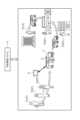
図1には、相乗り運行形態の概念図が示されている。相乗り運行形態に用いられる送迎車両Yは、複数の予約者P(P1,P2,P3)が同乗可能な自動車で構成されている。本実施形態における相乗り運行形態(所謂ライドシェア)は、自宅の近隣に位置する公共施設(市役所や駅等)、商業施設(スーパーや飲食店等)又は医療福祉施設(病院や老人ホーム等)といった施設を利用したい予約者Pが、安価に短距離移動できる運行形態である。 FIG. 1 shows a conceptual diagram of a carpooling mode. The shuttle vehicle Y used in the carpooling mode is composed of a car in which a plurality of reservation users P (P1, P2, P3) can ride together. In this embodiment, the form of carpooling (so-called ride sharing) refers to public facilities (city halls, stations, etc.), commercial facilities (supermarkets, restaurants, etc.), or medical and welfare facilities (hospitals, nursing homes, etc.) located near your home. This is a mode of operation that allows the reservation person P who wants to use the facility to travel short distances at low cost.
送迎車両Yは、旅客自動車運送事業を営む運行事業者に雇用された第二種運転免許を所有する運転手により運転される。送迎車両Yには、運転手が操作可能な運転手端末Dが搭載されており、この運転手端末Dと、運行事業者のオペレータが操作可能な運行事業者端末Sと、がインターネット回線を用いて無線通信可能に構成されている。運転手端末Dは、タブレット端末やスマートフォン等で構成されており、運行事業者端末Sは、パーソナルコンピューター等で構成されている。 The shuttle vehicle Y is driven by a driver who is employed by an operator that operates a passenger car transportation business and holds a class 2 driver's license. The shuttle vehicle Y is equipped with a driver terminal D that can be operated by the driver, and this driver terminal D and the operator terminal S that can be operated by the operator of the operator of the operator are connected via the Internet. It is configured to enable wireless communication. The driver terminal D is composed of a tablet terminal, a smartphone, etc., and the operator terminal S is composed of a personal computer etc.
予約管理システムXは、複数の予約者Pの予約内容(希望目的地や希望到着時刻等)に基づいて、複数の予約者Pが同乗する送迎車両Yの運行ルートや送迎時刻等を設定する。予約管理システムXは、予約管理事業者のオペレータが操作可能なパーソナルコンピューター等で構成されており、予約者Pからの電話等を受けたオペレータが予約者Pの予約内容を入力可能に構成されている。また、予約管理システムXは、予約者Pが所有するタブレット端末やスマートフォン等で構成される予約者端末Uとインターネット回線を用いて無線通信可能に構成されており、予約者Pが予約者端末Uに入力した予約内容又は予約確定内容を、予約者端末Uとの間で送受信することができる。 The reservation management system X sets, based on the reservation details of the plurality of reservationers P (desired destination, desired arrival time, etc.), the operating route, pick-up time, etc. of the shuttle vehicle Y in which the plurality of reservationers P ride together. The reservation management system There is. In addition, the reservation management system It is possible to send and receive the reservation details or reservation confirmation details inputted to and from the reservation user terminal U.
予約管理システムXは、運行事業者端末Sとインターネット回線を用いて有線又は無線通信可能に構成されており、設定した送迎車両Yの運行ルートや送迎時刻等を運行事業者端末Sに送信し、運行事業者端末S又は運行事業者のオペレータは、運転手端末D又は運転手に対して運行指示を実行する。 The reservation management system The operating company terminal S or the operator of the operating company issues operation instructions to the driver terminal D or the driver.
図1の例では、到着時刻:10時50分、目的地:市役所として予約者P1が予約管理事業者のオペレータに電話し、到着時刻:10時30分、目的地:〇〇内科として予約者P2が予約管理事業者のオペレータに電話し、到着時刻:10時45分、目的地:〇〇スーパーとして予約者P3が予約者端末Uに入力する。そして、予約管理事業者のオペレータが予約者P1及び予約者P2の予約内容を予約管理システムXに入力する。予約者P3の予約内容はインターネット回線を通じて自動的に予約管理システムXに入力される。次いで、予約管理システムXは、予約者P1,P2,P3の現在地(出発地の一例)と、市役所,〇〇内科及び〇〇スーパーの立地と、夫々の目的地への到着時刻とに基づいて、送迎車両Yの運行ルートと予約者P1,P2,P3の送迎時刻とを設定する。この設定された運行ルートや送迎時刻等は、予約管理システムXから運行事業者端末Sに送信され、運行事業者端末S又は運行事業者のオペレータが確認,承認をした上で、運転手端末D又は運転手に対して運行指示を実行する。 In the example in Figure 1, the reservation person P1 calls the operator of the reservation management company with arrival time: 10:50 and destination: City Hall, and the reservation person P1 calls the reservation management company's operator at arrival time: 10:30 and destination: 〇〇 Internal Medicine. P2 calls the operator of the reservation management company, and the reservation person P3 inputs arrival time: 10:45 and destination: 〇〇supermarket into the reservation person terminal U. Then, the operator of the reservation management company inputs the reservation details of the reservation person P1 and the reservation person P2 into the reservation management system X. The reservation details of the reservation person P3 are automatically input into the reservation management system X through the Internet line. Next, the reservation management system , the operation route of the shuttle vehicle Y and the pick-up and drop-off times of the reservation users P1, P2, and P3 are set. The set operating route, pick-up and drop-off times, etc. are sent from the reservation management system Or execute driving instructions to the driver.
図2には、予約管理システムXのブロック図が示されている。予約管理システムXは、表示部10と入力部11と記憶部12と通信部13とエリア設定部2と乗継地点設定部3と予約管理部4とを備えている。予約管理システムXの各機能部は各種処理を実行するCPUやメモリを中核としたソフトウェア、又はハードウェアとソフトウェアとの協働により構成されている。 FIG. 2 shows a block diagram of the reservation management system X. The reservation management system X includes a
表示部10は、コンピュータのディスプレイで構成されており、予約管理事業者のオペレータが操作可能な予約画面を表示する。詳細は後述するが、図4に表示部10の予約画面の一例が示されており、予約者Pから電話を受けた予約管理事業者のオペレータが出発地及び目的地等を入力すると、後述する予約管理部4にて予約者Pの要望に沿った予約手続を実行することができる。なお、この予約画面は、予約者Pが所有する予約者端末Uにおいても、予約者P自らが操作可能に構成されている。 The
入力部11は、マウスやキーボード等で構成されており、表示部10に表示された予約画面に対する予約管理事業者のオペレータの操作を受け付ける。例えば、マウス操作によりポインタを予約画面の所定位置に移動させ、マウスをその位置でクリックすることで所定の操作が実行される。The
記憶部12は、RAMやHDDといったハードウェアで構成されており、予約者Pの登録情報、予約者Pの予約内容、後述するエリア情報及び停留所情報、各種プログラム等が記憶されている。通信部13は、予約者端末Uや運行事業者端末Sとの間で有線又は無線で構成されるネットワークを介して送受信するためのインターフェースである。 The
エリア設定部2は、運行管理エリア設定部21と共有エリア設定部22と停留所設定部23とを有している。 The area setting section 2 includes an operation management
運行管理エリア設定部21は、予め登録された複数の運行管理エリアA,B,Cの何れかで運行する送迎車両Yを設定する(図3も参照)。「運行管理エリアA,B,C」とは、地理的に区画された所定の面積を持つエリアであって、設定された送迎車両Yが運行することができるエリアのことである。「送迎車両Yが複数の運行管理エリアA,B,Cの何れかで運行する」とは、運行管理エリアAで運行する送迎車両Y1と、運行管理エリアBで運行する送迎車両Y2と、運行管理エリアCで運行する送迎車両Y3と、が夫々異なる送迎車両Yであることを意味する。なお、2つ以上の運行管理エリアA,Bを跨って運行する送迎車両Yを設定しても良く、特に限定されない。また、運行管理エリア設定部21は、1つの運行管理エリアA,B,Cで運行する複数台の送迎車両Yを設定しても良いが、本実施形態では、1つの運行管理エリアA,B,Cで夫々1台の送迎車両Y1,Y2,Y3が運行するものとして説明する。The operation management
共有エリア設定部22は、2つの運行管理エリアA,B又は運行管理エリアB,C又は運行管理エリアA,Cの両方と隣接し、複数の運行管理エリアA,B,Cとは異なる共有エリアKにおいて、運行する送迎車両Yを設定する(図3も参照)。本実施形態における「共有エリアK」とは、隣接する複数の運行管理エリアA,B,Cで運行する複数の送迎車両Y1,Y2,Y3の全てが運行できるエリアのことを意味する。つまり、送迎車両Y1は、運行管理エリアA内、運行管理エリアAと共有エリアK間、共有エリアK内で運行することが可能である。同様に、送迎車両Y2は、運行管理エリアB内、運行管理エリアBと共有エリアK間、共有エリアK内で運行することが可能であり、送迎車両Y3は、運行管理エリアC内、運行管理エリアCと共有エリアK間、共有エリアK内で運行することが可能である。 The shared
停留所設定部23は、共有エリアK内で予約者Pが送迎車両Yを乗り継ぐための複数の乗継用停留所Tki(iは停留所番号)を設定すると共に、夫々の運行管理エリアA,B,C内で予約者Pが目的地として利用することが可能な複数の目的地用停留所Tti(iは停留所番号)を設定する(図3も参照)。図3では、運行管理エリアCにおいて目的地用停留所Ttiが設定されている例が示されている。本実施形態では、乗継用停留所Tkiとして、予約者Pが待機できる公共施設(駅やバス停等)や予約者Pが待ち時間を有効活用できる商業施設(薬局やコンビニエンスストア等)などが設定されている。また、目的地用停留所Ttiとして、予約者Pが日常、良く利用する公共施設(市役所や駅等)、商業施設(スーパーや飲食店等)又は医療福祉施設(病院や老人ホーム等)などが設定されている。なお、停留所設定部23は、夫々の運行管理エリアA,B,C内で予約者Pが出発地として利用することが可能な出発地用停留所を設定しても良い。 The
つまり、共有エリアK内で予約者Pが快適に滞在可能な公共施設や商業施設等を乗継地点として設定すれば、予約者Pは待ち時間を有効に活用することが可能となり、乗継地点となる施設においても利用者数を増やすことができる。また、予約者Pを増やしたい共有エリアK内の施設が乗継用停留所Tkiとして登録されたいといったニーズが高まり、乗継用停留所Tkiの登録数の増大が見込まれる。その結果、多数の乗継用停留所Tkiの中から、出発地と目的地とを結ぶ最短ルートの乗継地点を選択することが可能となり、予約者Pの利便性を高めることができる。 In other words, if a public facility or commercial facility, etc., where the reservation person P can stay comfortably within the common area K is set as a transit point, the reservation person P can effectively utilize the waiting time, and the transfer point It is also possible to increase the number of users at facilities that become In addition, there is a growing need for facilities in the common area K to be registered as transfer stops Tki to increase the number of reservations P, and an increase in the number of registrations of transfer stops Tki is expected. As a result, it becomes possible to select the transfer point of the shortest route connecting the departure point and the destination from among a large number of transfer stops Tki, and the convenience for the reservation person P can be improved.
乗継地点設定部3は、2つの運行管理エリアA,Cと隣接し且つ複数の運行管理エリアA,B,Cとは異なる共有エリアKにおいて、第一の送迎車両Y1に乗車した予約者Pが、第二の送迎車両Y3に乗り継ぐための乗継地点を設定する。図4~図8の例では、出発地を運行管理エリアA内とし、目的地を運行管理エリアC内の目的地用停留所Ttiの何れかとし、乗継地点を共有エリアK内の乗継用停留所Tkiの何れかとしている。 The transfer
図4の例では、乗継地点設定部3が、乗継地点としての複数の乗継用停留所Tkiの候補を表示部10や予約者Pの予約者端末Uの予約画面に表示させる(図4の2.を参照)。この乗継用停留所Tkiは、予約者Pが指定した出発地と目的地とに基づいて、移動時間が短い順に表示される。ただし、乗継用停留所Tkiの表示順は、直線距離が短い順に表示されても良く、予約者P自身が過去に利用した履歴順、利用頻度の高い施設順、類似属性の予約者P(例えば女性の高齢者)の利用頻度の高い施設順、予約管理システムXに対するスポンサー料の多い施設順等であっても良い。 In the example of FIG. 4, the transfer
そして、乗継地点設定部3は、予約者Pが選択した何れかの乗継用停留所Tkiを乗継地点として設定する。なお、図7に示すように、予約者Pが指定した出発地と目的地とに基づいて、乗継地点設定部3が1つの乗継地点を設定しても良い。この場合、乗継地点設定部3は、移動時間が最も短い施設、直線距離が最も短い施設又は利用頻度の高い施設等を乗継地点として設定する。これにより、予約者Pが何れかの乗継用停留所Tkiを選択する手間が省ける。 Then, the transfer
予約管理部4は、2つの運行管理エリアA,C(又は運行管理エリアA,B若しくは運行管理エリアB,C)のうち、予約者Pが指定した出発地を含む第一の運行管理エリアA(又は運行管理エリアB若しくは運行管理エリアC)で運行している第一の送迎車両Y1(又は送迎車両Y2若しくは送迎車両Y3)、及び、予約者Pが指定した目的地を含む第二の運行管理エリアC(又は運行管理エリアA若しくは運行管理エリアB)で運行している第二の送迎車両Y3(又は送迎車両Y1若しくは送迎車両Y2)の予約手続を一連の予約手続として実行する。図2に示すように、予約管理部4は、予約確認部41とルート演算部42と表示制御部43とを有している。 The
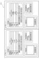
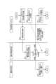
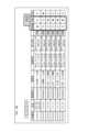
予約確認部41は、予約管理システムXの通信部13を介して、運行事業者端末Sとの間で予約内容を確認する偽装請負防止機能を構成している。図9には、予約確認部41の偽装請負防止機能のフロー図が示されており、図10には、操作画面例が示されている。図10に示す操作画面は、予約管理システムXのオペレータが閲覧可能となっており、運行事業者端末Sのオペレータが閲覧、操作可能となっている。なお、緊急時には、予約管理システムXのオペレータが図10に示す操作画面を操作可能に構成しても良い。 The
図9に示すように、予約管理システムXのオペレータが予約者Pからの予約受付を行い、予約内容を確定する(♯11)。次いで、予約管理システムXの通信部13を介して、運行事業者端末Sに承諾依頼をプッシュ通知する(♯12)。プッシュ通知とは、運行事業者端末Sにおいて、アプリケーションが起動されていなくても通知を表示することである。そして、運行事業者端末Sのオペレータは、承諾依頼通知を受け取り、予約内容を確認する(♯13)。次いで、運行事業者端末Sのオペレータは、例えば図10に示す操作画面を操作して、予約内容の諾否判定を行う(♯14)。図10の操作画面例では、予約番号、氏名、電話番号、乗降場、乗降日時及び受付日時で構成される予約内容、諾否判定のラジオボタンがこの順で配置されている。予約管理システムXが運行事業者端末Sに承諾依頼を通知した時点では、諾否判定の未確認ボタンにチェックが入っている。 As shown in FIG. 9, the operator of the reservation management system X accepts a reservation from the reservation person P and finalizes the reservation details (#11). Next, a push notification of the approval request is sent to the operator terminal S via the
図9に戻り、運行事業者端末Sのオペレータが予約内容を承諾した場合、運転手端末Dが予約内容を受信し、送迎車両Yが予約内容に基づいて運行する(♯15)。運行事業者端末Sのオペレータが予約内容を未承諾の場合は、操作画面を確認した予約管理システムXのオペレータが、予約をキャンセルし、予約者Pに予約者端末Uの予約画面やメール、電話等で連絡する(♯16、♯17)。 Returning to FIG. 9, when the operator of the operating company terminal S approves the reservation details, the driver terminal D receives the reservation details, and the shuttle vehicle Y operates based on the reservation details (#15). If the operator of the operator terminal S of the operator does not accept the reservation details, the operator of the reservation management system etc. (#16, #17).
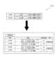
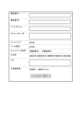
図11には、予約者Pの所持する予約者端末Uにショートメールを送るための設定画面が示されている。この設定画面では、電話番号、メールアドレス、オペレータメモ、コールバック、メール配信、ショートメール配信、その他、メモ、自宅乗降場がこの順で評されている。コールバックとは、予約内容、予約キャンセルや予約変更等を予約管理システムXのオペレータから予約者Pに電話連絡するためのオプションである。メール配信又はショートメール配信とは、予約内容、予約キャンセルや予約変更等を予約管理システムXのオペレータから予約者Pにメール連絡するためのオプションである。自宅乗降場では、予約者Pが出発地や目的地として予め自宅を登録しておくことで、図4又は図7に示す出発地や目的地として自宅を選択できる。Figure 11 shows a setting screen for sending a short message to the reservation terminal U held by reservation person P. On this setting screen, the following fields are displayed in order: phone number, email address, operator memo, callback, email delivery, short message delivery, other, memo, and home stop. Callback is an option for the operator of the reservation management system X to contact reservation person P by phone regarding reservation details, reservation cancellation, reservation changes, etc. Email delivery or short message delivery is an option for the operator of the reservation management system X to contact reservation person P by email regarding reservation details, reservation cancellation, reservation changes, etc. At home stop, reservation person P can select his/her home as the departure point or destination shown in Figure 4 or Figure 7 by registering his/her home as the departure point or destination in advance.
一方、運行開始時刻より所定時間前までに諾否判定のラジオボタンが未確認の状態であれば、運行事業者端末Sのオペレータが運行事業者端末Sのオペレータに対して、対応を促す。これら一連の機能を予約確認部41が実行することにより、予約管理システムXを運用する事業者以外の者が勝手に予約を受け付ける偽装請負を防止することができる。 On the other hand, if the radio button for acceptance/rejection determination is unconfirmed by a predetermined time before the service start time, the operator of the service provider terminal S urges the operator of the service provider terminal S to take a response. By having the
ルート演算部42は、図4に示すように、予約者Pが指定した出発地、目的地、到着時刻及び号車指定等の予約内容(入力内容の一例)に基づき、送迎車両Yの運行ルートを演算する(図4の3.4.参照)。このルート演算部42は、予約者Pが指定した出発地、目的地、到着時刻及び号車指定に基づいて、移動時間が短い順に運行ルートを演算しても良いし、直線距離が短い順に運行ルートを演算しても良い。予約者Pが選択した乗継用停留所Tkiに基づいて運行ルートを演算しても良い。また、図7に示すように、予約者Pが指定した出発地及び目的地のみに基づいて、移動時間が短い順に運行ルートを演算しても良いし、直線距離が短い順に運行ルートを演算しても良い。図8には、ルート演算部42が直線距離の短い順に運行ルートを演算する一例が示されている。ルート演算部42は、出発地と目的地とを結ぶ直線上近傍にある乗継地点aをメイン候補として設定し、この乗継地点aから半径数キロメートル以内にあり、且つ出発地から近い順に乗継地点b,cのサブ候補として設定する。なお、ルート演算部42における乗継地点の設定に際し、予約者P自身が過去に利用した履歴順、利用頻度の高い施設順、類似属性の予約者P(例えば女性の高齢者)の利用頻度の高い施設順、予約管理システムXに対するスポンサー料の多い施設順等を考慮しても良い。 As shown in FIG. 4, the
さらに、ルート演算部42は、複数の予約者Pが入力した予約内容に基づいて、複数の予約者Pが同乗する送迎車両Yの運行ルートや送迎時刻等を演算する。例えば、出発地となる運行管理エリアA内の自宅から共有エリアKの乗継用停留所Tkiまで運行する第一の送迎車両Y1に複数の予約者Pが同乗可能であれば、複数の出発地から乗継場所まで送迎する順番を加味した運行ルートを演算する。また、共有エリアKの乗継用停留所Tkiから運行管理エリアCの目的地用停留所Ttiまで複数の予約者Pが同乗可能であれば、乗継場所から複数の目的地まで送迎する順番を加味した運行ルートを演算する。 Further, the
なお、このルート演算部42は、機械学習により、出発地から乗継地点までの運行予定と、乗継地点から目的地までの運行予定と、乗継地点の候補と、を自動的に抽出することが好ましい。この機械学習は、過去のデータに基づく教師あり学習であっても良いし、人工知能を用いたディープラーニングであっても良い。It is preferable that the
表示制御部43は、出発地から乗継地点設定部3で設定された乗継地点までの第一の予約手続と共に乗継地点から目的地までの第二の予約手続を、予約管理システムXの表示部10や予約者Pの予約者端末U(以下、「予約画面」と言う。)に表示させる。この表示例が、図4~図7に示されている。 The
図4~図7に示すように、ルート演算部42が出発地から目的地までの予約内容に基づいて運行ルートを生成し、表示制御部43が出発地から乗継地点までの第一の予約手続及び乗継地点から目的地までの第二の予約手続を予約画面に表示させる(図4の3.4.、図7の下図参照)。そして、予約者Pが「予約する」ボタンをクリックすることにより、予約手続が実行される。このように、予約者Pが指定した出発地から目的地までの予約内容に基づいて、出発地から乗継地点設定部3で設定された乗継地点までの第一の予約手続と共に乗継地点から目的地までの第二の予約手続を一元的に実行すれば、予約者Pに提示可能な運行バリエーションを増やすことができる。ここで、「予約手続を表示させる」とは、予約管理部4が予約手続を実行するために必要な項目を表示させることであり、予約画面には、運行ルートの候補及び予約実行ボタンが少なくとも設けられている。 As shown in FIGS. 4 to 7, the
図4に示すように、ルート演算部42が予約者Pの選択した乗継地点(図4の2.参照)に基づいて運行ルートを生成し、表示制御部43が出発地から乗継地点までの第一の予約手続及び乗継地点から目的地までの第二の予約手続を予約画面に表示させても良い。このように、選択された乗継地点に基づいて予約手続を実行すれば、予約者P自身が利用したい商業施設等を乗継地点として選択することができる。 As shown in FIG. 4, the
また、図4及び図7に示すように、表示制御部43は、出発地から乗継地点までの運行予定(時間と経路)と、乗継地点から目的地までの運行予定(時間と経路)と、乗継地点と、を予約画面に表示させても良い(図4の3.4.、図7の下図参照)。これにより、出発地及び乗継地点間の運行予定と、乗継地点及び目的地間の運行予定と、乗継地点とを予約画面に表示すれば、予約者Pが運行バリエーションを迅速に把握できる。この乗継地点の候補は、図4に示すように予約画面に複数表示させることが好ましい。これにより、予約者Pの好みに合った乗継地点を選択することが可能となり、予約者Pの希望に合った乗継用停留所Tkiにて買い物等を楽しむことができる。よって、予約者Pは、乗継地点での待ち時間を有効に活用することができる。 In addition, as shown in FIGS. 4 and 7, the
また、図5に示すように、表示制御部43は、出発地から乗継地点までの予約結果と、乗継地点から目的地までの予約結果と、を予約画面に表示させても良い。図5に示す予約情報をクリックすると、図6に示すように、予約結果が時系列で表示されることが好ましい。このように、出発地及び乗継地点間の予約結果と、乗継地点及び目的地間の予約結果とを予約画面に表示すれば、予約者Pが予約内容を迅速に把握可能となり、予約変更を簡単にできる。また、図4及び図7に示すように、表示制御部43は、出発地から乗継地点までの候補と、乗継地点から目的地までの候補と、を予約画面に表示させても良い(図4の3.4.、図7の下図参照)。 Further, as shown in FIG. 5, the
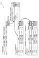
図12には、予約管理システムXの制御フローが示されている。 FIG. 12 shows the control flow of the reservation management system X.
まず、出発地、目的地等の予約内容を予約者Pが予約管理事業者のオペレータに電話し、電話を受けた予約管理事業者のオペレータが入力部11を介して予約内容を入力する、又は、予約者P自身が予約者端末Uに予約内容を入力することで、予約を受け付ける(図4の1.、図7の上図参照、♯51)。次いで、ルート演算部42は、出発地と目的地とが位置する運行管理エリアが同一であるか否かを判定し、同一であれば、そのエリアA,B,C,K内で運行する送迎車両Yの運行ルートを生成する(♯52Yes、♯53)。 First, the reservation person P calls the operator of the reservation management company with reservation details such as departure point and destination, and the operator of the reservation management company who received the call inputs the reservation details via the
♯52の判定の結果、出発地と目的地とが位置するエリアA,B,C,Kが同一でなければ、ルート演算部42は、出発地が運行管理エリアA,B,C内にあるか共有エリアK内にあるか判定する(♯52Nо、♯56)。♯56の判定の結果、出発地が共有エリアK内に位置しており、且つ、目的地が共有エリアKに隣接する運行管理エリアA,B,Cであれば、目的地が位置するエリアA,B,C内で運行する送迎車両Yの運行ルートを生成する(♯57Yes、♯58)。一方、♯57の判定の結果、目的地が運行管理エリアA,B,C外であれば、予約不可とする(♯57Nо、♯64)。 As a result of the determination in #52, if the areas A, B, C, and K where the departure point and destination are located are not the same, the
♯56の判定の結果、出発地が運行管理エリアA,B,C内に位置しており、且つ、目的地が共有エリアK内であれば、ルート演算部42は、出発地が位置するエリアA,B,C,K内で運行する送迎車両Yの運行ルートを生成する(♯59Yes、♯60)。♯56の判定の結果、出発地が運行管理エリアA,B,C内に位置しており、且つ、目的地が共有エリアK内でなければ、目的地が共有エリアKに隣接する他の運行管理エリアA,B,C内(出発地とは異なる運行管理エリアA,B,C内)に位置するか否かを判定する(♯59Nо、♯61)。 As a result of the determination in #56, if the departure point is located within the operation management areas A, B, or C, and the destination is within the shared area K, the
♯61の判定の結果、目的地が共有エリアKに隣接する他の運行管理エリアA,B,C内に位置していれば、乗継地点設定部3が、乗継地点としての複数の乗継用停留所Tkiの候補を予約画面に表示させ、予約者Pが選択した何れかの乗継用停留所Tkiを乗継地点として設定する(図4の2.参照、♯61Yes、♯62)。次いで、ルート演算部42は、出発地が位置する運行管理エリアA,B,C内で運行する送迎車両Yの運行ルート、及び、目的地が位置する運行管理エリアA,B,C内で運行する送迎車両Yの運行ルートを生成する(♯63)。一方、♯61の判定の結果、目的地が運行管理エリアA,B,C外であれば、予約不可とする(♯61Nо、♯64)。 As a result of the determination in #61, if the destination is located in other operation management areas A, B, and C adjacent to the common area K, the transfer
上述した♯53、♯58、♯60又は♯63でルート演算部42が運行ルートを生成した場合、複数の予約者Pによる相乗りが可能であるか否かを判定し、相乗り可能であればルート演算部42は乗降順番を加味した運行ルートを生成し(♯54Yes、♯55)、相乗り不可であれば生成された運行ルートを変更しない(♯54No)。そして、表示制御部43は、表示部10又は予約者端末Uに運行ルートを表示させる(図4の3.4、図7の下図参照)。次いで、予約者Pが予約ボタンを押下した場合、表示制御部43は、図5~図6に示すように予約完了画面を表示部10又は予約者端末Uに表示させる。When the
このように、第一の送迎車両Y1(又は送迎車両Y2若しくは送迎車両Y3)が運行している第一の運行管理エリアA(又は運行管理エリアB若しくは運行管理エリアC)及び第二の送迎車両Y3(又は送迎車両Y1若しくは送迎車両Y2)が運行している第二の運行管理エリアC(又は運行管理エリアA若しくは運行管理エリアB)と隣接し、複数の運行管理エリアA,B,Cとは異なる共有エリアKを設定している。つまり、共有エリアK内で予約者Pが快適に滞在可能な公共施設や商業施設等を乗継地点として設定すれば、予約者Pは待ち時間を有効に活用することが可能となり、乗継地点となる施設においても利用者数を増やすことができる。また、共有エリアKは運行管理エリアA,B,Cと隣接しているため、送迎車両Yが走行していた運行管理エリアA,B,Cに迅速に戻ることが可能となり、各運行管理エリアA,B,Cに送迎車両Yが不足するといった事態を回避することができる。 In this way, the first transportation management area A (or transportation management area B or transportation management area C) where the first transportation vehicle Y1 (or transportation vehicle Y2 or transportation vehicle Y3) is operating and the second transportation vehicle Adjacent to the second operation management area C (or operation management area A or operation management area B) where Y3 (or shuttle vehicle Y1 or shuttle vehicle Y2) is operating, and connected to multiple operation management areas A, B, and C. has set up a different shared area K. In other words, if a public facility or commercial facility, etc., where the reservation person P can stay comfortably within the common area K is set as a transit point, the reservation person P will be able to make effective use of the waiting time. It is also possible to increase the number of users at facilities that become In addition, since the shared area K is adjacent to the operation management areas A, B, and C, it is possible to quickly return to the operation management areas A, B, and C where the shuttle vehicle Y was traveling, and each operation management area It is possible to avoid a situation where there is a shortage of shuttle vehicles Y for A, B, and C.
[その他の実施形態]
(1)送迎車両Yが運行する複数の運行管理エリアA,B,Cは、3つに限定されず、2つ以上であれば幾つであっても良い。
(2)運行管理エリアA,B,Cは、送迎車両Yが営業許可を得ているエリアであっても良い。また、送迎車両Yが運行可能な運行管理エリアA,B,Cを限定しなくても良く、送迎車両Yが何れの運行管理エリアA,B,Cでも運行可能に構成しても良い。つまり、予約者Pが乗車する運行管理エリアAから運行管理エリアCまでの送迎車両Yが同一車両となる場合があり得る。[Other embodiments]
(1) The plurality of operation management areas A, B, and C in which the shuttle vehicle Y operates is not limited to three, but may be any number as long as it is two or more.
(2) The operation management areas A, B, and C may be areas where the shuttle vehicle Y has a business license. Further, the operation management areas A, B, and C in which the shuttle vehicle Y can operate need not be limited, and the configuration may be such that the shuttle vehicle Y can operate in any of the operation management areas A, B, and C. In other words, there is a possibility that the shuttle vehicle Y from the operation management area A to the operation management area C in which the reservation person P rides is the same vehicle.
本発明は、設定された複数の運行管理エリアにおける送迎車両の予約を管理する予約管理システムに利用可能である。 INDUSTRIAL APPLICABILITY The present invention can be used in a reservation management system that manages reservations for shuttle vehicles in a plurality of set operation management areas.
3 :乗継地点設定部
4 :予約管理部
10 :表示部
A,B,C:運行管理エリア
K :共有エリア
P :予約者
Tki:乗継用停留所
a,b,c:乗継地点3: Transfer point setting section 4: Reservation management section 10: Display sections A, B, C: Operation management area K: Shared area P: Reservation person Tki: Transfer stops a, b, c: Transfer point
Claims (10)
Translated fromJapanese前記複数の運行管理エリアのうち、予約者が指定した出発地を含む第一の運行管理エリアで運行可能な第一の送迎車両、及び、前記予約者が指定した目的地を含む第二の運行管理エリアで運行可能な第二の送迎車両の予約手続を実行する予約管理部と、
前記第一の運行管理エリア及び前記第二の運行管理エリアの両方と隣接し且つ前記第一の運行管理エリア及び前記第二の運行管理エリアとは異なる共有エリアにおいて、前記第一の送迎車両に乗車した前記予約者が、前記第二の送迎車両に乗り継ぐための乗継地点を設定する乗継地点設定部と、を備え、
前記予約管理部は、前記出発地から前記乗継地点設定部で設定された前記乗継地点までの第一の前記予約手続と前記乗継地点から前記目的地までの第二の前記予約手続とを一連の前記予約手続として実行可能に構成されている予約管理システム。 A reservation management system that manages reservations formultiple shuttle vehicles in multiple set operation management areas,
Amongtheplurality of operation management areas, a first shuttle vehicle that can be operated in thefirst operation management area that includes the departure point specified by the reservation person, and afirst shuttle vehicle that can operate in the first operation management area that includes the departure point specified by the reservation person. a reservation management department that executes the reservation procedure for asecond shuttle vehicle that can operate in thesecond operation management area;
In a shared areaadjacent to both the first operation management area and the second operation management area and different from thefirstoperation management area and the second operation management area , the first transportation a transfer point setting unit for setting a transfer point for the reservation person who has boarded the vehicle to transfer to the second shuttle vehicle;
The reservation management section includes a first reservation procedure from the departure point to the transfer point set by the transfer point setting section and a second reservation procedure from the transfer point to the destination. A reservation management system configured to be able to execute a series of the reservation procedures.
前記複数の運行管理エリアのうち、予約者が指定した出発地を含む第一の運行管理エリアで運行可能な第一の送迎車両、及び、前記予約者が指定した目的地を含む第二の運行管理エリアで運行可能な第二の送迎車両の予約手続を実行する予約管理部と、
前記第一の運行管理エリア及び前記第二の運行管理エリアの両方と隣接し且つ前記第一の運行管理エリア及び前記第二の運行管理エリアとは異なる共有エリアにおいて、前記第一の送迎車両に乗車した前記予約者が、前記第二の送迎車両に乗り継ぐための乗継地点を設定する乗継地点設定部と、を備え、
前記乗継地点設定部は、前記乗継地点を複数有しており、
前記予約管理部は、前記出発地から前記乗継地点設定部で設定された前記乗継地点までの第一の前記予約手続と前記乗継地点から前記目的地までの第二の前記予約手続とを一連の前記予約手続として実行可能に構成されており、複数の前記乗継地点の中から前記予約者が選択した前記乗継地点に基づいて、前記第一の予約手続及び前記第二の予約手続を実行する予約管理システム。A reservation management system that manages reservations for multiple shuttle vehicles in multiple set operation management areas,
Among the plurality of operation management areas, a first shuttle vehicle that can be operated in a first operation management area that includes the departure point specified by the reservation person, and a second operation that includes the destination specified by the reservation person. a reservation management department that executes reservation procedures for a second shuttle vehicle that can operate in the management area;
In a shared area adjacent to both the first operation management area and the second operation management area and different from the first operation management area and the second operation management area, the first shuttle vehicle a transfer point setting unit for setting a transfer point for the reservation person who has boarded the vehicle to transfer to the second shuttle vehicle;
The transfer point setting unit has a plurality of transfer points,
The reservation management sectionincludes a first reservation procedure from the departure point to the transfer point set by the transfer point setting section and a second reservation procedure from the transfer point to the destination. is configured to be able to be executed as a series of the reservation procedures, and the first reservation procedure and the second reservation are made based on the transfer point selected by the reservation person from among the plurality of transfer points. A reservation management system that executes procedures.
前記予約管理部は、前記出発地から前記乗継地点までの運行予定と、前記乗継地点から前記目的地までの運行予定と、前記乗継地点と、を前記予約画面に表示させる請求項1から4の何れか一項に記載の予約管理システム。 Further comprising a display section having a reservation screen,
2. The reservation management unit displays on the reservation screen an operation schedule from the departure point to the transfer point, an operation schedule from the transfer point to the destination, and the transfer point. 4. The reservation management system according to any one of 4.
前記複数の運行管理エリアのうち予約者が指定した出発地を含む第一の運行管理エリアと前記共有エリアとにおいて運行可能な第一の送迎車両、及び、前記複数の運行管理エリアのうち前記予約者が指定した目的地を含む第二の運行管理エリアと前記共有エリアとにおいて運行可能な第二の送迎車両の予約手続を実行する予約管理部と、 A first shuttle vehicle that can operate in the common area and a first operation management area that includes the departure point specified by the reservation person among the plurality of operation management areas, and the reservation among the plurality of operation management areas. a reservation management unit that executes a reservation procedure for a second shuttle vehicle that can operate in a second operation management area that includes a destination specified by the person and the common area;
前記共有エリアにおいて、前記第一の送迎車両に乗車した前記予約者が、前記第二の送迎車両に乗り継ぐための乗継地点を設定する乗継地点設定部と、を備え、a transfer point setting unit that sets a transfer point for the reservation holder who boards the first shuttle vehicle to transfer to the second shuttle vehicle in the shared area,
前記予約管理部は、前記出発地から前記乗継地点設定部で設定された前記乗継地点までの第一の前記予約手続と前記乗継地点から前記目的地までの第二の前記予約手続とを一連の前記予約手続として実行可能に構成されている予約管理システム。 The reservation management section includes a first reservation procedure from the departure point to the transfer point set by the transfer point setting section and a second reservation procedure from the transfer point to the destination. A reservation management system configured to be able to execute a series of the reservation procedures.
Priority Applications (1)
| Application Number | Priority Date | Filing Date | Title |
|---|---|---|---|
| JP2019235609AJP7456154B2 (en) | 2019-12-26 | 2019-12-26 | Reservation management system |
Applications Claiming Priority (1)
| Application Number | Priority Date | Filing Date | Title |
|---|---|---|---|
| JP2019235609AJP7456154B2 (en) | 2019-12-26 | 2019-12-26 | Reservation management system |
Publications (2)
| Publication Number | Publication Date |
|---|---|
| JP2021105762A JP2021105762A (en) | 2021-07-26 |
| JP7456154B2true JP7456154B2 (en) | 2024-03-27 |
Family
ID=76918814
Family Applications (1)
| Application Number | Title | Priority Date | Filing Date |
|---|---|---|---|
| JP2019235609AActiveJP7456154B2 (en) | 2019-12-26 | 2019-12-26 | Reservation management system |
Country Status (1)
| Country | Link |
|---|---|
| JP (1) | JP7456154B2 (en) |
Families Citing this family (1)
| Publication number | Priority date | Publication date | Assignee | Title |
|---|---|---|---|---|
| JP7628990B2 (en)* | 2022-09-08 | 2025-02-12 | トヨタ自動車株式会社 | Information Processing Method |
Citations (3)
| Publication number | Priority date | Publication date | Assignee | Title |
|---|---|---|---|---|
| JP2004302942A (en) | 2003-03-31 | 2004-10-28 | Fujitsu Ltd | Mobile vehicle allocation program and mobile vehicle allocation method considering business area |
| JP2018205829A (en) | 2017-05-30 | 2018-12-27 | 本田技研工業株式会社 | Ride share management device, ride share management method, and program |
| WO2019163816A1 (en) | 2018-02-22 | 2019-08-29 | 本田技研工業株式会社 | Vehicle control system, vehicle control method, and program |
- 2019
- 2019-12-26JPJP2019235609Apatent/JP7456154B2/enactiveActive
Patent Citations (3)
| Publication number | Priority date | Publication date | Assignee | Title |
|---|---|---|---|---|
| JP2004302942A (en) | 2003-03-31 | 2004-10-28 | Fujitsu Ltd | Mobile vehicle allocation program and mobile vehicle allocation method considering business area |
| JP2018205829A (en) | 2017-05-30 | 2018-12-27 | 本田技研工業株式会社 | Ride share management device, ride share management method, and program |
| WO2019163816A1 (en) | 2018-02-22 | 2019-08-29 | 本田技研工業株式会社 | Vehicle control system, vehicle control method, and program |
Also Published As
| Publication number | Publication date |
|---|---|
| JP2021105762A (en) | 2021-07-26 |
Similar Documents
| Publication | Publication Date | Title |
|---|---|---|
| JP6208273B2 (en) | Carpooling support system, carpooling support method, and carpooling support apparatus | |
| JP5935887B2 (en) | On-demand vehicle operation management device, on-demand vehicle operation management method, and on-demand vehicle operation management system | |
| JP2022119818A (en) | Commercial vehicle operation device and method | |
| CN110678884A (en) | System and method for customizable pre-dispatch monotony for transportation services | |
| JP2004062490A (en) | Carpool agent negotiation system and carpool agent negotiation method | |
| KR101565304B1 (en) | Method for Reservation Service of Call Taxi | |
| JP2002098537A (en) | Facility information providing device and recording medium | |
| JP2015035044A (en) | Carpooling support system | |
| KR101794552B1 (en) | method of sharing taxies service provided based on chatting among preserve passengers | |
| JP6135384B2 (en) | Carpooling support system | |
| JP6906373B2 (en) | Systems, methods, and programs for managing vehicle travel plans | |
| JP2004227262A (en) | Quick response vehicle getting on and off system, method and program | |
| JP2011123844A (en) | Taxi dispatch system and taxi dispatch processing device | |
| JP7456154B2 (en) | Reservation management system | |
| KR102052602B1 (en) | Seat information providing system and the method thereof suing spatial information technlogy | |
| JP7097002B2 (en) | Operation management device used in vehicle operation management system and vehicle operation management system | |
| JP7196456B2 (en) | Ride-sharing assistance systems and programs | |
| JP2021006959A (en) | Device, program and method for vehicle allocation management | |
| JP5916522B2 (en) | Life innovation support device | |
| JP7402027B2 (en) | Synergistic movement support system | |
| JP6409159B1 (en) | Bus arrangement operation method, server and program | |
| JP7598087B2 (en) | Reservation Management System | |
| JP7383330B2 (en) | Dispatch device, dispatch method, and program | |
| JP2016162438A (en) | Elderly transportation assist system through car sharing | |
| JP7023399B1 (en) | Server equipment and programs |
Legal Events
| Date | Code | Title | Description |
|---|---|---|---|
| A80 | Written request to apply exceptions to lack of novelty of invention | Free format text:JAPANESE INTERMEDIATE CODE: A80 Effective date:20200127 | |
| A621 | Written request for application examination | Free format text:JAPANESE INTERMEDIATE CODE: A621 Effective date:20221014 | |
| A977 | Report on retrieval | Free format text:JAPANESE INTERMEDIATE CODE: A971007 Effective date:20230825 | |
| A131 | Notification of reasons for refusal | Free format text:JAPANESE INTERMEDIATE CODE: A131 Effective date:20231003 | |
| A521 | Request for written amendment filed | Free format text:JAPANESE INTERMEDIATE CODE: A523 Effective date:20231128 | |
| TRDD | Decision of grant or rejection written | ||
| A01 | Written decision to grant a patent or to grant a registration (utility model) | Free format text:JAPANESE INTERMEDIATE CODE: A01 Effective date:20240213 | |
| A61 | First payment of annual fees (during grant procedure) | Free format text:JAPANESE INTERMEDIATE CODE: A61 Effective date:20240226 | |
| R150 | Certificate of patent or registration of utility model | Ref document number:7456154 Country of ref document:JP Free format text:JAPANESE INTERMEDIATE CODE: R150 |