JP7450608B2 - Fluid injector system, method for preventing fluid backflow, and computer program product - Google Patents
Fluid injector system, method for preventing fluid backflow, and computer program productDownload PDFInfo
- Publication number
- JP7450608B2 JP7450608B2JP2021510782AJP2021510782AJP7450608B2JP 7450608 B2JP7450608 B2JP 7450608B2JP 2021510782 AJP2021510782 AJP 2021510782AJP 2021510782 AJP2021510782 AJP 2021510782AJP 7450608 B2JP7450608 B2JP 7450608B2
- Authority
- JP
- Japan
- Prior art keywords
- fluid
- pressure
- conduit
- reservoir
- processor
- Prior art date
- Legal status (The legal status is an assumption and is not a legal conclusion. Google has not performed a legal analysis and makes no representation as to the accuracy of the status listed.)
- Active
Links
- 239000012530fluidSubstances0.000titleclaimsdescription1215
- 238000000034methodMethods0.000titleclaimsdescription84
- 238000004590computer programMethods0.000titleclaimsdescription49
- 239000007924injectionSubstances0.000claimsdescription95
- 238000002347injectionMethods0.000claimsdescription95
- 238000004891communicationMethods0.000claimsdescription32
- 238000001802infusionMethods0.000claimsdescription27
- 230000008859changeEffects0.000claimsdescription23
- 230000003247decreasing effectEffects0.000claimsdescription18
- 238000001514detection methodMethods0.000claimsdescription9
- 230000004044responseEffects0.000claimsdescription9
- 230000003213activating effectEffects0.000claimsdescription8
- 238000012544monitoring processMethods0.000claimsdescription6
- 230000000977initiatory effectEffects0.000claimsdescription3
- FAPWRFPIFSIZLT-UHFFFAOYSA-MSodium chlorideChemical compound[Na+].[Cl-]FAPWRFPIFSIZLT-UHFFFAOYSA-M0.000description101
- 239000011780sodium chlorideSubstances0.000description98
- 239000002872contrast mediaSubstances0.000description69
- 230000009977dual effectEffects0.000description17
- 238000002156mixingMethods0.000description12
- 238000011049fillingMethods0.000description7
- 230000003287optical effectEffects0.000description7
- 230000006399behaviorEffects0.000description6
- 238000005096rolling processMethods0.000description5
- 238000001208nuclear magnetic resonance pulse sequenceMethods0.000description4
- 230000008569processEffects0.000description4
- 238000010992refluxMethods0.000description4
- 230000000694effectsEffects0.000description3
- 238000003384imaging methodMethods0.000description3
- 230000037361pathwayEffects0.000description3
- 238000012545processingMethods0.000description3
- 239000007787solidSubstances0.000description3
- 238000013459approachMethods0.000description2
- 230000008901benefitEffects0.000description2
- 239000003795chemical substances by applicationSubstances0.000description2
- 238000002591computed tomographyMethods0.000description2
- 238000003745diagnosisMethods0.000description2
- 238000005516engineering processMethods0.000description2
- 238000011010flushing procedureMethods0.000description2
- 230000006870functionEffects0.000description2
- 230000003993interactionEffects0.000description2
- 230000007246mechanismEffects0.000description2
- 239000000203mixtureSubstances0.000description2
- 238000010926purgeMethods0.000description2
- 238000009877renderingMethods0.000description2
- 238000012360testing methodMethods0.000description2
- 230000002792vascularEffects0.000description2
- 210000005166vasculatureAnatomy0.000description2
- 238000012795verificationMethods0.000description2
- 230000000007visual effectEffects0.000description2
- 239000002699waste materialSubstances0.000description2
- 206010015866ExtravasationDiseases0.000description1
- 238000012879PET imagingMethods0.000description1
- 206010067171RegurgitationDiseases0.000description1
- 230000004913activationEffects0.000description1
- 230000003044adaptive effectEffects0.000description1
- 230000002411adverseEffects0.000description1
- 238000002583angiographyMethods0.000description1
- 230000004888barrier functionEffects0.000description1
- 238000009530blood pressure measurementMethods0.000description1
- 230000006835compressionEffects0.000description1
- 238000007906compressionMethods0.000description1
- 238000011109contaminationMethods0.000description1
- 229940039231contrast mediaDrugs0.000description1
- 238000013500data storageMethods0.000description1
- 230000003111delayed effectEffects0.000description1
- 230000001419dependent effectEffects0.000description1
- 238000002405diagnostic procedureMethods0.000description1
- 238000010586diagramMethods0.000description1
- 238000006073displacement reactionMethods0.000description1
- 230000036251extravasationEffects0.000description1
- 230000006872improvementEffects0.000description1
- 238000011068loading methodMethods0.000description1
- 238000002595magnetic resonance imagingMethods0.000description1
- 239000000463materialSubstances0.000description1
- 239000012092media componentSubstances0.000description1
- 238000012986modificationMethods0.000description1
- 230000004048modificationEffects0.000description1
- 230000002093peripheral effectEffects0.000description1
- 239000002504physiological saline solutionSubstances0.000description1
- 230000002265preventionEffects0.000description1
- 230000037452primingEffects0.000description1
- 230000001105regulatory effectEffects0.000description1
- 239000000243solutionSubstances0.000description1
- 238000002560therapeutic procedureMethods0.000description1
- 238000012546transferMethods0.000description1
- 230000009466transformationEffects0.000description1
- 230000007723transport mechanismEffects0.000description1
- 238000011144upstream manufacturingMethods0.000description1
- 210000001835visceraAnatomy0.000description1
- -1without limitationSubstances0.000description1
Images


Classifications
- A—HUMAN NECESSITIES
- A61—MEDICAL OR VETERINARY SCIENCE; HYGIENE
- A61M—DEVICES FOR INTRODUCING MEDIA INTO, OR ONTO, THE BODY; DEVICES FOR TRANSDUCING BODY MEDIA OR FOR TAKING MEDIA FROM THE BODY; DEVICES FOR PRODUCING OR ENDING SLEEP OR STUPOR
- A61M5/00—Devices for bringing media into the body in a subcutaneous, intra-vascular or intramuscular way; Accessories therefor, e.g. filling or cleaning devices, arm-rests
- A61M5/14—Infusion devices, e.g. infusing by gravity; Blood infusion; Accessories therefor
- A61M5/168—Means for controlling media flow to the body or for metering media to the body, e.g. drip meters, counters ; Monitoring media flow to the body
- A61M5/16804—Flow controllers
- A61M5/16827—Flow controllers controlling delivery of multiple fluids, e.g. sequencing, mixing or via separate flow-paths
- A—HUMAN NECESSITIES
- A61—MEDICAL OR VETERINARY SCIENCE; HYGIENE
- A61M—DEVICES FOR INTRODUCING MEDIA INTO, OR ONTO, THE BODY; DEVICES FOR TRANSDUCING BODY MEDIA OR FOR TAKING MEDIA FROM THE BODY; DEVICES FOR PRODUCING OR ENDING SLEEP OR STUPOR
- A61M5/00—Devices for bringing media into the body in a subcutaneous, intra-vascular or intramuscular way; Accessories therefor, e.g. filling or cleaning devices, arm-rests
- A61M5/14—Infusion devices, e.g. infusing by gravity; Blood infusion; Accessories therefor
- A61M5/142—Pressure infusion, e.g. using pumps
- A61M5/14212—Pumping with an aspiration and an expulsion action
- A61M5/14216—Reciprocating piston type
- A61M5/1422—Reciprocating piston type with double acting or multiple pistons
- A—HUMAN NECESSITIES
- A61—MEDICAL OR VETERINARY SCIENCE; HYGIENE
- A61M—DEVICES FOR INTRODUCING MEDIA INTO, OR ONTO, THE BODY; DEVICES FOR TRANSDUCING BODY MEDIA OR FOR TAKING MEDIA FROM THE BODY; DEVICES FOR PRODUCING OR ENDING SLEEP OR STUPOR
- A61M5/00—Devices for bringing media into the body in a subcutaneous, intra-vascular or intramuscular way; Accessories therefor, e.g. filling or cleaning devices, arm-rests
- A61M5/14—Infusion devices, e.g. infusing by gravity; Blood infusion; Accessories therefor
- A61M5/168—Means for controlling media flow to the body or for metering media to the body, e.g. drip meters, counters ; Monitoring media flow to the body
- A61M5/16831—Monitoring, detecting, signalling or eliminating infusion flow anomalies
- A61M5/16854—Monitoring, detecting, signalling or eliminating infusion flow anomalies by monitoring line pressure
- A—HUMAN NECESSITIES
- A61—MEDICAL OR VETERINARY SCIENCE; HYGIENE
- A61M—DEVICES FOR INTRODUCING MEDIA INTO, OR ONTO, THE BODY; DEVICES FOR TRANSDUCING BODY MEDIA OR FOR TAKING MEDIA FROM THE BODY; DEVICES FOR PRODUCING OR ENDING SLEEP OR STUPOR
- A61M5/00—Devices for bringing media into the body in a subcutaneous, intra-vascular or intramuscular way; Accessories therefor, e.g. filling or cleaning devices, arm-rests
- A61M5/178—Syringes
- A61M5/20—Automatic syringes, e.g. with automatically actuated piston rod, with automatic needle injection, filling automatically
- A61M5/2066—Automatic syringes, e.g. with automatically actuated piston rod, with automatic needle injection, filling automatically comprising means for injection of two or more media, e.g. by mixing
- A—HUMAN NECESSITIES
- A61—MEDICAL OR VETERINARY SCIENCE; HYGIENE
- A61M—DEVICES FOR INTRODUCING MEDIA INTO, OR ONTO, THE BODY; DEVICES FOR TRANSDUCING BODY MEDIA OR FOR TAKING MEDIA FROM THE BODY; DEVICES FOR PRODUCING OR ENDING SLEEP OR STUPOR
- A61M5/00—Devices for bringing media into the body in a subcutaneous, intra-vascular or intramuscular way; Accessories therefor, e.g. filling or cleaning devices, arm-rests
- A61M5/14—Infusion devices, e.g. infusing by gravity; Blood infusion; Accessories therefor
- A61M2005/1401—Functional features
- A61M2005/1406—Minimizing backflow along the delivery catheter track
- A—HUMAN NECESSITIES
- A61—MEDICAL OR VETERINARY SCIENCE; HYGIENE
- A61M—DEVICES FOR INTRODUCING MEDIA INTO, OR ONTO, THE BODY; DEVICES FOR TRANSDUCING BODY MEDIA OR FOR TAKING MEDIA FROM THE BODY; DEVICES FOR PRODUCING OR ENDING SLEEP OR STUPOR
- A61M5/00—Devices for bringing media into the body in a subcutaneous, intra-vascular or intramuscular way; Accessories therefor, e.g. filling or cleaning devices, arm-rests
- A61M5/14—Infusion devices, e.g. infusing by gravity; Blood infusion; Accessories therefor
- A61M5/142—Pressure infusion, e.g. using pumps
- A61M2005/14208—Pressure infusion, e.g. using pumps with a programmable infusion control system, characterised by the infusion program
- A—HUMAN NECESSITIES
- A61—MEDICAL OR VETERINARY SCIENCE; HYGIENE
- A61M—DEVICES FOR INTRODUCING MEDIA INTO, OR ONTO, THE BODY; DEVICES FOR TRANSDUCING BODY MEDIA OR FOR TAKING MEDIA FROM THE BODY; DEVICES FOR PRODUCING OR ENDING SLEEP OR STUPOR
- A61M5/00—Devices for bringing media into the body in a subcutaneous, intra-vascular or intramuscular way; Accessories therefor, e.g. filling or cleaning devices, arm-rests
- A61M5/178—Syringes
- A61M5/31—Details
- A61M2005/3128—Incorporating one-way valves, e.g. pressure-relief or non-return valves
- A—HUMAN NECESSITIES
- A61—MEDICAL OR VETERINARY SCIENCE; HYGIENE
- A61M—DEVICES FOR INTRODUCING MEDIA INTO, OR ONTO, THE BODY; DEVICES FOR TRANSDUCING BODY MEDIA OR FOR TAKING MEDIA FROM THE BODY; DEVICES FOR PRODUCING OR ENDING SLEEP OR STUPOR
- A61M5/00—Devices for bringing media into the body in a subcutaneous, intra-vascular or intramuscular way; Accessories therefor, e.g. filling or cleaning devices, arm-rests
- A61M5/007—Devices for bringing media into the body in a subcutaneous, intra-vascular or intramuscular way; Accessories therefor, e.g. filling or cleaning devices, arm-rests for contrast media
Landscapes
- Health & Medical Sciences (AREA)
- Vascular Medicine (AREA)
- Engineering & Computer Science (AREA)
- Anesthesiology (AREA)
- Biomedical Technology (AREA)
- Heart & Thoracic Surgery (AREA)
- Hematology (AREA)
- Life Sciences & Earth Sciences (AREA)
- Animal Behavior & Ethology (AREA)
- General Health & Medical Sciences (AREA)
- Public Health (AREA)
- Veterinary Medicine (AREA)
- Infusion, Injection, And Reservoir Apparatuses (AREA)
Description
Translated fromJapanese 関連出願の相互参照
本出願は、2018年8月28日に出願された米国仮特許出願第62/723,739号明細書の恩典を主張し、その開示はその全体が参照により本明細書に組み込まれる。 CROSS-REFERENCE TO RELATED APPLICATIONS This application claims the benefit of U.S. Provisional Patent Application No. 62/723,739, filed August 28, 2018, the disclosure of which is hereby incorporated by reference in its entirety. Incorporated.
本開示は、流体注入器システムに関し、具体的には、注入プロトコルを実行するように構成された流体注入器システムに関する。本開示は、流体注入器システムを使用する流体注入処置中に、第2流体リザーバからの第2流体が第1流体リザーバ内に逆流するのを防止する方法を、さらに対象とする。本開示はまた、流体注入器システムを使用する流体注入処置中に、第2流体リザーバからの少なくとも第2流体が第1流体リザーバ内に逆流するのを防止するコンピュータプログラム製品も対象とする。 TECHNICAL FIELD This disclosure relates to fluid infuser systems, and specifically to fluid infuser systems configured to perform infusion protocols. The present disclosure is further directed to a method of preventing backflow of a second fluid from a second fluid reservoir into a first fluid reservoir during a fluid injection procedure using a fluid infuser system. The present disclosure is also directed to a computer program product that prevents at least a second fluid from a second fluid reservoir from flowing back into a first fluid reservoir during a fluid injection procedure using a fluid injector system.
多くの医療診断および治療処置において、内科医または放射線科医などの医師は、患者に1つ以上の流体を注入する。近年、血管造影法、コンピュータ断層撮影法(CT)、分子イメージング(PETイメージングなど)および磁気共鳴画像法(MRI)などの処置で使用するために、流体の加圧注入用の注入器作動式シリンジおよび電動注入器が多数開発されてきた。これらの処置では、画像化プロセス中に特定の内蔵または身体の部分を強調するために、造影剤などの流体が使用され得る。一方、造影剤のボーラスの完全な注入を保証するため、および造影剤の濃度を調整するために、生理食塩水または類似のフラッシング剤が使用され得る。 In many medical diagnostic and therapeutic procedures, a physician, such as an internist or radiologist, injects one or more fluids into a patient. Injector-actuated syringes for pressurized injection of fluids have recently been developed for use in procedures such as angiography, computed tomography (CT), molecular imaging (such as PET imaging) and magnetic resonance imaging (MRI). and a number of electric injectors have been developed. In these procedures, fluids such as contrast agents may be used to highlight particular internal organs or body parts during the imaging process. On the other hand, saline or a similar flushing agent may be used to ensure complete injection of the contrast agent bolus and to adjust the contrast agent concentration.
2つ以上の流体タイプを送達するように設定されたマルチリザーバ消耗品を有する流体注入器システムでは、異なるリザーバ内での2つの流体の意図しない混合の防止が望まれる。使い捨てリザーバの使用寿命にわたって複数の患者に流体を送達するために1つまたは複数の同じリザーバが使用される複数患者用途において、これは特に適切であろう。生理食塩水リザーバへの造影剤の意図しない混合は、テスト注入またはフラッシュフェーズ中の患者への投与にエラーを生じる可能性がある。逆に、造影剤リザーバ内への生理食塩水の意図しない混合は、望ましくない希釈された投与をもたらし、診断に適さない、または低品質の画像を生成する可能性がある。したがって、流体注入器システム、流体の逆流を防止する方法、およびこれらで使用するためのコンピュータプログラム製品には、改善の余地がある。 In fluid injector systems with multi-reservoir consumables configured to deliver more than one fluid type, prevention of unintentional mixing of two fluids within different reservoirs is desired. This may be particularly appropriate in multi-patient applications where the same reservoir or reservoirs are used to deliver fluid to multiple patients over the useful life of the disposable reservoir. Unintentional mixing of contrast agent into the saline reservoir can result in errors in test injection or patient administration during the flush phase. Conversely, unintentional mixing of saline into the contrast agent reservoir may result in an undesirably diluted administration and produce images that are unsuitable for diagnosis or of poor quality. Accordingly, there is room for improvement in fluid injector systems, methods for preventing backflow of fluid, and computer program products for use therewith.
これらの需要および他の需要は、改善された流体注入器システム、流体の逆流を防止する方法、およびこれらで使用するためのコンピュータプログラム製品を対象とする、開示される例または態様の実施形態によって満たされる。 These and other needs are met by embodiments of the disclosed examples or aspects that are directed to improved fluid injector systems, methods of preventing fluid backflow, and computer program products for use therewith. It is filled.
本開示のいくつかの例または態様では、注入プロトコルを実行するように構成された流体注入器システムが提供される。流体注入器システムは、第1流体リザーバから流体導管を通る第1流体、および第2流体リザーバから流体導管を通る少なくとも第2流体を、加圧および注入するように構成された2つ以上の駆動コンポーネントの各々に動作可能に関連付けられた制御装置を含み、流体導管は、第1流体リザーバおよび少なくとも第2流体リザーバと選択的に流体連通している。制御装置は、流体導管を通る第2流体を加圧および注入するように2つ以上の駆動コンポーネントの第2駆動コンポーネントを作動させ、第2駆動コンポーネントが作動している間、流体導管を通る第2流体の第1流体リザーバ内への逆流を防止するために流体導管内の第1流体と第2流体との間の流頭界面を作製するために、第1流体の間欠パルスを導入するように2つ以上の駆動コンポーネントの第1駆動コンポーネントを作動させるようにプログラムまたは構成された、少なくとも1つのプロセッサを有する。 In some examples or aspects of the present disclosure, a fluid infuser system configured to perform an infusion protocol is provided. The fluid injector system includes two or more drives configured to pressurize and inject a first fluid from a first fluid reservoir through a fluid conduit and at least a second fluid from a second fluid reservoir through a fluid conduit. A control device is operably associated with each of the components, and the fluid conduit is in selective fluid communication with the first fluid reservoir and at least the second fluid reservoir. The controller operates a second drive component of the two or more drive components to pressurize and inject a second fluid through the fluid conduit, while the second drive component is actuated. 2 to introduce intermittent pulses of the first fluid to create a flow front interface between the first fluid and the second fluid within the fluid conduit to prevent backflow of the fluid into the first fluid reservoir; at least one processor programmed or configured to operate a first drive component of the two or more drive components.
本開示のいくつかの例または態様では、注入プロトコルを実行するように構成された別の流体注入器システムが提供される。流体注入器システムは、第1流体リザーバから流体導管を通る第1流体、および第2流体リザーバから流体導管を通る少なくとも第2流体を、加圧および注入するように構成された2つ以上の駆動コンポーネントの各々に動作可能に関連付けられた制御装置を含み、流体導管は、第1流体リザーバおよび少なくとも第2流体リザーバと選択的に流体連通している。制御装置は、流体導管を通る第2流体を加圧および注入するように2つ以上の駆動コンポーネントの第2駆動コンポーネントを作動させ、第2駆動コンポーネントが作動している間、流体導管を通る第2流体の第1流体リザーバ内への逆流を防止するために流体導管内の第1流体と第2流体との間の流頭界面を作製するために、第1流体の間欠パルスを導入するように2つ以上の駆動コンポーネントの第1駆動コンポーネントを作動させ、第1流体の圧力が第2流体の圧力と実質的に同じである圧力に到達するまで第1流体の間欠パルスを導入し続け、第1流体の間欠パルスを減少させ、第1流体流量の第1流体および第2流体流量の第2流体を、流体導管を通る第1流体および第2流体の所望の比率で送達し、第1流体リザーバ内の圧力と第2流体リザーバ内の圧力との差が第1所定値に到達するか否かを判断するために、第1流体および第2流体の注入中に第1流体リザーバ内の圧力および第2流体リザーバ内の圧力を監視するか、または流体導管内の注入圧力を監視して、注入圧力が第2所定値だけ変化するか否かを判断し、第1所定値および第2所定値のうちの対応するものに到達すると、第2流体が第1流体リザーバに侵入するのを防止するために、流体導管を通る第1流体の間欠パルスを再開する、ようにプログラムまたは構成された、少なくとも1つのプロセッサを有する。 In some examples or aspects of the present disclosure, another fluid infuser system configured to perform an infusion protocol is provided. The fluid injector system includes two or more drives configured to pressurize and inject a first fluid from a first fluid reservoir through a fluid conduit and at least a second fluid from a second fluid reservoir through a fluid conduit. A control device is operably associated with each of the components, and the fluid conduit is in selective fluid communication with the first fluid reservoir and at least the second fluid reservoir. The controller operates a second drive component of the two or more drive components to pressurize and inject a second fluid through the fluid conduit, while the second drive component is actuated. 2 to introduce intermittent pulses of the first fluid to create a flow front interface between the first fluid and the second fluid within the fluid conduit to prevent backflow of the fluid into the first fluid reservoir; activating a first drive component of the two or more drive components to continue introducing intermittent pulses of the first fluid until the pressure of the first fluid reaches a pressure that is substantially the same as the pressure of the second fluid; reducing the intermittent pulses of the first fluid to deliver a first fluid flow rate of the first fluid and a second fluid flow rate of the second fluid at a desired ratio of the first fluid and the second fluid through the fluid conduit; the pressure in the first fluid reservoir during injection of the first fluid and the second fluid to determine whether the difference between the pressure in the fluid reservoir and the pressure in the second fluid reservoir reaches a first predetermined value. monitoring the pressure and the pressure in the second fluid reservoir or monitoring the injection pressure in the fluid conduit to determine whether the injection pressure changes by a second predetermined value; programmed or configured to resume intermittent pulsing of the first fluid through the fluid conduit to prevent the second fluid from entering the first fluid reservoir upon reaching a corresponding one of the predetermined values; and at least one processor.
本開示のいくつかの例または態様では、第2流体リザーバからの第2流体が、注入プロトコルを実行するように構成された流体注入器システムの第1流体リザーバ内に逆流するのを防止する方法が提供される。方法は、第1駆動コンポーネントおよび第2駆動コンポーネントに動作可能に関連付けられた制御装置を提供するステップであって、第1駆動コンポーネントは、患者の流体導管を通じて第1流体を加圧および注入するように構成されており、第2駆動コンポーネントは、流体導管を通じて第2流体リザーバから少なくとも第2流体を加圧および注入するように構成されている、ステップと、流体導管を通じて第2流体を加圧および注入するように、2つ以上の駆動コンポーネントの第2駆動コンポーネントを作動させるステップと、第2駆動コンポーネントが作動している間、流体導管を通る第2流体の第1流体リザーバ内への逆流を防止するために流体導管内の第1流体と第2流体との間の流頭界面を作製するために、第1流体の間欠パルスを導入するように2つ以上の駆動コンポーネントの第1駆動コンポーネントを作動させるステップとを含む。 In some examples or aspects of the present disclosure, a method of preventing a second fluid from a second fluid reservoir from flowing back into a first fluid reservoir of a fluid infuser system configured to perform an injection protocol. is provided. The method includes providing a controller operably associated with a first drive component and a second drive component, the first drive component configured to pressurize and infuse a first fluid through a fluid conduit of a patient. the second drive component configured to pressurize and inject at least a second fluid from the second fluid reservoir through the fluid conduit; actuating a second drive component of the two or more drive components to inject, and while the second drive component is actuating, causing backflow of the second fluid through the fluid conduit into the first fluid reservoir; a first drive component of the two or more drive components to introduce intermittent pulses of the first fluid to create a flow front interface between the first fluid and the second fluid within the fluid conduit to prevent and activating the.
本開示のいくつかの例または態様では、注入プロトコルを実行するように構成された流体注入器システムを使用して、第2流体リザーバからの少なくとも第2流体が第1流体リザーバ内に逆流するのを防止するためのコンピュータプログラム製品が提供される。流体注入器システムは、流体導管を通じて第1流体を加圧および注入するように構成された第1駆動コンポーネント、ならびに流体導管を通じて第2流体を加圧および注入するように構成された少なくとも第2駆動コンポーネントの各々に動作可能に関連付けられた制御装置を含み、流体導管は、第1流体リザーバおよび第2流体リザーバと選択的に流体連通している。コンピュータプログラム製品は、少なくとも1つのプロセッサによって実行されると、少なくとも1つのプロセッサに、流体導管を通る第2流体を加圧および注入するように第2駆動コンポーネントを作動させ、第2駆動コンポーネントが作動している間、流体導管を通る第2流体の第1流体リザーバ内への逆流を防止するために流体導管内の第1流体と第2流体との間の流頭界面を作製するために、第1流体の間欠パルスを導入するように第1駆動コンポーネントを作動させる、1つ以上の命令を含む非一時的なコンピュータ可読媒体を有する。 In some examples or aspects of the present disclosure, at least a second fluid from a second fluid reservoir flows back into a first fluid reservoir using a fluid infuser system configured to perform an infusion protocol. A computer program product is provided for preventing. The fluid injector system includes a first drive component configured to pressurize and inject a first fluid through the fluid conduit and at least a second drive component configured to pressurize and inject a second fluid through the fluid conduit. A control device is operably associated with each of the components, and the fluid conduit is in selective fluid communication with the first fluid reservoir and the second fluid reservoir. The computer program product, when executed by the at least one processor, causes the at least one processor to actuate a second drive component to pressurize and inject a second fluid through the fluid conduit; to create a flow front interface between the first fluid and the second fluid within the fluid conduit to prevent backflow of the second fluid through the fluid conduit into the first fluid reservoir; a non-transitory computer-readable medium containing one or more instructions for activating a first drive component to introduce intermittent pulses of a first fluid;
本開示の他の様々な態様は、以下の条項の1つ以上に記載されている。 Various other aspects of the disclosure are described in one or more of the following sections.
条項1.注入プロトコルを実行するように構成された流体注入器システムであって、流体注入器システムは、第1流体リザーバから流体導管を通る第1流体、および第2流体リザーバから流体導管を通る少なくとも第2流体を、加圧および注入するように構成された2つ以上の駆動コンポーネントの各々に動作可能に関連付けられた制御装置であって、流体導管は第1流体リザーバおよび少なくとも第2流体リザーバと選択的に流体連通している、制御装置を含み、制御装置は、流体導管を通る第2流体を加圧および注入するように2つ以上の駆動コンポーネントの第2駆動コンポーネントを作動させ、第2駆動コンポーネントが作動している間、流体導管を通る第2流体の第1流体リザーバ内への逆流を防止するために流体導管内の第1流体と第2流体との間の流頭界面を作製するために、第1流体の間欠パルスを導入するように2つ以上の駆動コンポーネントの第1駆動コンポーネントを作動させるようにプログラムまたは構成された少なくとも1つのプロセッサを含む、流体注入器システム。 Clause 1. A fluid infuser system configured to perform an injection protocol, the fluid infuser system comprising: a first fluid passing through a fluid conduit from a first fluid reservoir; and at least a second fluid passing through a fluid conduit from a second fluid reservoir. a control device operably associated with each of the two or more drive components configured to pressurize and inject a fluid, the fluid conduit being selectively connected to the first fluid reservoir and at least the second fluid reservoir; a controller in fluid communication with the controller, the controller actuating a second drive component of the two or more drive components to pressurize and inject a second fluid through the fluid conduit; to create a flow front interface between the first fluid and the second fluid within the fluid conduit to prevent backflow of the second fluid through the fluid conduit into the first fluid reservoir during operation of the fluid conduit; at least one processor programmed or configured to operate a first drive component of the two or more drive components to introduce intermittent pulses of a first fluid.
条項2.少なくとも1つのプロセッサは、第1流体の圧力が第2流体の圧力と実質的に同じ圧力に到達するまで第1流体の間欠パルスを導入し続けるように2つ以上の駆動コンポーネントの第1駆動コンポーネントを作動させるように、さらにプログラムまたは構成されている、条項1に記載の流体注入器システム。 Clause 2. The at least one processor controls the first drive component of the two or more drive components to continue to introduce intermittent pulses of the first fluid until the pressure of the first fluid reaches substantially the same pressure as the pressure of the second fluid. A fluid injector system according to clause 1, further programmed or configured to operate.
条項3.少なくとも1つのプロセッサは、第2流体リザーバと比較した第1流体リザーバ内の圧力差、第1流体と第2流体との所望の比率と比較した第1流体と第2流体との観察された比率の差、流体導管内の流体流量または圧力の変化、第2流体の逆流の検出、第1流体と第2流体との流体特性の差、およびこれらの任意の組み合わせのうちの少なくとも1つに基づいて、増加する周波数、減少する周波数、増加する振幅、減少する振幅、およびこれらの任意の組み合わせからなる群より選択された周波数または振幅で第1流体の間欠パルスを導入するように2つ以上の駆動コンポーネントの第1駆動コンポーネントをさらに作動させるように、さらにプログラムまたは構成されている、条項1または2に記載の流体注入器システム。 Clause 3. The at least one processor determines the pressure difference in the first fluid reservoir compared to the second fluid reservoir, the observed ratio of the first fluid and the second fluid compared to the desired ratio of the first fluid and the second fluid. , a change in fluid flow rate or pressure within the fluid conduit, detection of backflow of the second fluid, a difference in fluid properties between the first fluid and the second fluid, and any combination thereof. and introducing intermittent pulses of the first fluid at a frequency or amplitude selected from the group consisting of increasing frequency, decreasing frequency, increasing amplitude, decreasing amplitude, and any combination thereof. 3. The fluid infuser system of clause 1 or 2, further programmed or configured to further actuate a first drive component of the drive components.
条項4.少なくとも1つのプロセッサは、第1流体の周波数または振幅のうちの少なくとも1つを減少させるように、または第1流体の間欠パルスの波形を変化させるように、ならびに流体導管を通る第1流体と第2流体との所望の比率で第1流体流量の第1流体と第2流体流量の第2流体を送達するように、さらにプログラムまたは構成されている、条項1から3のいずれか一項に記載の流体注入器システム。 Clause 4. The at least one processor is configured to reduce at least one of the frequency or amplitude of the first fluid, or to change the waveform of the intermittent pulses of the first fluid, and the first fluid through the fluid conduit. as described in any one of clauses 1 to 3, further programmed or configured to deliver a first fluid at a first fluid flow rate and a second fluid at a second fluid flow rate in a desired ratio with the two fluids; fluid injector system.
条項5.少なくとも1つのプロセッサは、第1流体リザーバ内の圧力と第2流体リザーバ内の圧力との差が第1所定値に到達するか否かを判断するために、第1流体および第2流体の注入中に第1流体リザーバ内の圧力および第2流体リザーバ内の圧力のうちの少なくとも1つを監視するように、さらにプログラムまたは構成されている、条項1から4のいずれか一項に記載の流体注入器システム。 Clause 5. The at least one processor injects the first fluid and the second fluid to determine whether the difference between the pressure in the first fluid reservoir and the pressure in the second fluid reservoir reaches a first predetermined value. the fluid according to any one of clauses 1 to 4, further programmed or configured to monitor at least one of the pressure in the first fluid reservoir and the pressure in the second fluid reservoir during Injector system.
条項6.第1所定値に到達すると、少なくとも1つのプロセッサは、第2流体が第1流体リザーバに侵入するのを防止するために、流体導管を通る第1流体の間欠パルスの第2のセットを開始するように、さらにプログラムまたは構成されている、条項5に記載の流体注入器システム。 Clause 6. Upon reaching the first predetermined value, the at least one processor initiates a second set of intermittent pulses of the first fluid through the fluid conduit to prevent the second fluid from entering the first fluid reservoir. A fluid injector system according to clause 5, further programmed or configured to:
条項7.少なくとも1つのプロセッサは、流体導管内の注入圧力を監視し、注入圧力が第2所定値だけ変化するか否かを判断するようにさらにプログラムまたは構成されている、条項1から4のいずれか一項に記載の流体注入器システム。 Clause 7. The at least one processor is further programmed or configured to monitor the injection pressure within the fluid conduit and determine whether the injection pressure changes by a second predetermined value. Fluid injector system as described in Section.
条項8.少なくとも1つのプロセッサは、プログラムされた注入プロトコルおよびユーザ入力情報のうちの少なくとも1つに基づいて所定の注入圧力を計算し、これに応答して、間欠パルスの事前設定された波形を調整するようにさらにプログラムまたは構成されている、条項1から4のいずれか一項に記載の流体注入器システム。 Clause 8. The at least one processor is configured to calculate a predetermined infusion pressure based on at least one of a programmed infusion protocol and user input information, and responsively adjust the preset waveform of the intermittent pulse. A fluid infuser system according to any one of clauses 1 to 4, further programmed or configured to.
条項9.少なくとも1つのプロセッサは、流体導管内の注入圧力の変化率を継続的に監視し、これに応答して、ルックアップテーブルまたは所定のアルゴリズムに基づいて間欠パルスのパルス間隔、パルス流量、およびパルス量のうちの少なくとも1つを調整するようにさらにプログラムまたは構成されている、条項1から8のいずれか一項に記載の流体注入器システム。 Clause 9. The at least one processor continuously monitors the rate of change of injection pressure within the fluid conduit and, in response, adjusts the pulse interval, pulse flow rate, and pulse amount of the intermittent pulses based on a look-up table or a predetermined algorithm. A fluid infuser system according to any one of clauses 1 to 8, further programmed or configured to adjust at least one of:
条項10.第1流体の間欠パルスが導入されると、少なくとも1つのプロセッサは、ルックアップテーブルまたは所定のアルゴリズムからパルス間隔を選択するようにさらにプログラムまたは構成されている、条項1から9のいずれか一項に記載の流体注入器システム。 Clause 10. Any one of clauses 1 to 9, wherein the at least one processor is further programmed or configured to select a pulse interval from a look-up table or a predetermined algorithm when the intermittent pulses of the first fluid are introduced. Fluid infuser system as described in.
条項11.第1流体の間欠パルスが導入されると、少なくとも1つのプロセッサは、ルックアップテーブルまたは所定のアルゴリズムからパルス流量を選択するようにさらにプログラムまたは構成されている、条項10に記載の流体注入器システム。
条項12.第1流体の間欠パルスが導入されると、少なくとも1つのプロセッサは、ルックアップテーブルまたは所定のアルゴリズムからパルス量を選択するようにさらにプログラムまたは構成されている、条項1から11のいずれか一項に記載の流体注入器システム。
条項13.ルックアップテーブルおよび所定のアルゴリズムのうちの少なくとも1つがメモリ装置に格納されている、条項10から12のいずれか一項に記載の流体注入器システム。
条項14.第1流体の圧力が第2流体の圧力と実質的に同じ圧力に到達する前に、40ミリリットル未満の第1流体が流体導管内に導入される、条項1から13のいずれか一項に記載の流体注入器システム。
条項15.第1流体の圧力が第2流体の圧力と実質的に同じ圧力に到達する前に、25ミリリットル未満の第1流体が流体導管内に導入される、条項14に記載の流体注入器システム。 Article 15. 15. The fluid injector system of
条項16.流体導管内の第1流体と第2流体との間の流頭界面を作製するために第1駆動コンポーネントが第1流体の間欠パルスを導入している間、流体導管内に導入される第1流体の総量は、ユーザがプログラムした量と15ミリリットルとの合計よりも少ない、条項1から15のいずれか一項に記載の流体注入器システム。
条項17.第1駆動コンポーネントが作動すると、第1流体リザーバの容量が増加し、第2流体のいずれも第1流体リザーバに侵入しない、条項1から16のいずれか一項に記載の流体注入器システム。
条項18.注入プロトコルを実行するように構成された流体注入器システムであって、流体注入器システムは、第1流体リザーバから流体導管を通る第1流体、および第2流体リザーバから流体導管を通る少なくとも第2流体を、加圧および注入するように構成された2つ以上の駆動コンポーネントの各々に動作可能に関連付けられた制御装置であって、流体導管は第1流体リザーバおよび少なくとも第2流体リザーバと選択的に流体連通している、制御装置を含み、制御装置は、流体導管を通る第2流体を加圧および注入するように2つ以上の駆動コンポーネントの第2駆動コンポーネントを作動させ、第2駆動コンポーネントが作動している間、流体導管を通る第2流体の第1流体リザーバ内への逆流を防止するために流体導管内の第1流体と第2流体との間の流頭界面を作製するために、第1流体の間欠パルスを導入するように2つ以上の駆動コンポーネントの第1駆動コンポーネントを作動させ、第1流体の圧力が第2流体の圧力と実質的に同じ圧力に到達するまで第1流体の間欠パルスを導入し続け、第1流体の周波数および振幅のうちの少なくとも1つを減少させるかまたは第1流体の間欠パルスの波形を変更し、第1流体流量の第1流体および第2流体流量の第2流体を、流体導管を通る第1流体および第2流体の所望の比率で送達し、第1流体リザーバ内の圧力と第2流体リザーバ内の圧力との差が第1所定値に到達するか否かを判断するために、第1流体および第2流体の注入中に第1流体リザーバ内の圧力および第2流体リザーバ内の圧力のうちの少なくとも1つを監視するか、または流体導管内の注入圧力を監視して、注入圧力が第2所定値だけ変化するか否かを判断し、第1所定値および第2所定値のうちの対応するものに到達すると、第2流体が第1流体リザーバに侵入するのを防止するために、流体導管を通る第1流体の間欠パルスの第2のセットを開始する、ようにプログラムまたは構成された、少なくとも1つのプロセッサを含む、流体注入器システム。 Article 18. A fluid infuser system configured to perform an injection protocol, the fluid infuser system comprising: a first fluid passing through a fluid conduit from a first fluid reservoir; and at least a second fluid passing through a fluid conduit from a second fluid reservoir. a control device operably associated with each of the two or more drive components configured to pressurize and inject a fluid, the fluid conduit being selectively connected to the first fluid reservoir and at least the second fluid reservoir; a controller in fluid communication with the controller, the controller actuating a second drive component of the two or more drive components to pressurize and inject a second fluid through the fluid conduit; for creating a flow front interface between the first fluid and the second fluid within the fluid conduit to prevent backflow of the second fluid through the fluid conduit into the first fluid reservoir during operation of the fluid conduit; actuating a first drive component of the two or more drive components to introduce intermittent pulses of the first fluid until the pressure of the first fluid reaches substantially the same pressure as the pressure of the second fluid; continue to introduce intermittent pulses of the first fluid, reduce at least one of the frequency and amplitude of the first fluid, or change the waveform of the intermittent pulses of the first fluid, and increase the flow rate of the first fluid and the first fluid; 2 fluid flow rates of the second fluid at a desired ratio of the first fluid and the second fluid through the fluid conduit such that the difference between the pressure in the first fluid reservoir and the pressure in the second fluid reservoir is a first predetermined amount. monitoring at least one of the pressure in the first fluid reservoir and the pressure in the second fluid reservoir during injection of the first fluid and the second fluid to determine whether the value is reached; or monitoring the injection pressure within the fluid conduit to determine whether the injection pressure changes by a second predetermined value, and upon reaching a corresponding one of the first predetermined value and the second predetermined value; at least one processor programmed or configured to initiate a second set of intermittent pulses of the first fluid through the fluid conduit to prevent fluid from entering the first fluid reservoir; Fluid injector system.
条項19.少なくとも1つのプロセッサは、第2流体リザーバと比較した第1流体リザーバ内の圧力差、第1流体と第2流体との所望の比率と比較した第1流体と第2流体との観察された比率の差、流体導管内の流体流量または圧力の変化、第2流体の逆流の検出、第1流体と第2流体との流体特性の差、およびこれらの任意の組み合わせのうちの少なくとも1つに基づいて、増加する周波数、減少する周波数、増加する振幅、減少する振幅、およびこれらの任意の組み合わせからなる群より選択された周波数または振幅で第1流体の間欠パルスを導入するように2つ以上の駆動コンポーネントの第1駆動コンポーネントをさらに作動させるように、さらにプログラムまたは構成されている、条項18に記載の流体注入器システム。
条項20.少なくとも1つのプロセッサは、プログラムされた注入プロトコルおよびユーザ入力情報のうちの少なくとも1つに基づいて所定の注入圧力を計算し、これに応答して、間欠パルスの事前設定された波形を調整するようにさらにプログラムまたは構成されている、条項18または19に記載の流体注入器システム。
条項21.少なくとも1つのプロセッサは、流体導管内の注入圧力の変化率を継続的に監視し、これに応答して、ルックアップテーブルまたは所定のアルゴリズムに基づいて間欠パルスのパルス間隔、パルス流量、およびパルス量のうちの少なくとも1つを調整するようにさらにプログラムまたは構成されている、条項18から20のいずれか一項に記載の流体注入器システム。 Article 21. The at least one processor continuously monitors the rate of change of injection pressure within the fluid conduit and, in response, adjusts the pulse interval, pulse flow rate, and pulse amount of the intermittent pulses based on a look-up table or a predetermined algorithm. A fluid infuser system according to any one of clauses 18 to 20, further programmed or configured to adjust at least one of the following:
条項22.第1流体の間欠パルスが導入されると、少なくとも1つのプロセッサは、ルックアップテーブルまたは所定のアルゴリズムからパルス間隔を選択するようにさらにプログラムまたは構成されている、条項18から21のいずれか一項に記載の流体注入器システム。 Article 22. Any one of clauses 18 to 21, wherein the at least one processor is further programmed or configured to select the pulse interval from a look-up table or a predetermined algorithm when the intermittent pulses of the first fluid are introduced. Fluid infuser system as described in.
条項23.第1流体の間欠パルスが導入されると、少なくとも1つのプロセッサは、ルックアップテーブルまたは所定のアルゴリズムからパルス流量を選択するようにさらにプログラムまたは構成されている、条項22に記載の流体注入器システム。 Article 23. The fluid injector system of clause 22, wherein the at least one processor is further programmed or configured to select the pulse flow rate from a look-up table or a predetermined algorithm upon introduction of the intermittent pulses of the first fluid. .
条項24.第1流体の間欠パルスが導入されると、少なくとも1つのプロセッサは、ルックアップテーブルまたは所定のアルゴリズムからパルス量を選択するようにさらにプログラムまたは構成されている、条項18から23のいずれか一項に記載の流体注入器システム。 Article 24. Any one of clauses 18 to 23, wherein the at least one processor is further programmed or configured to select the pulse amount from a look-up table or a predetermined algorithm when the intermittent pulses of the first fluid are introduced. Fluid infuser system as described in.
条項25.ルックアップテーブルおよび所定のアルゴリズムのうちの少なくとも1つがメモリ装置に格納されている、条項22から24のいずれか一項に記載の流体注入器システム。 Article 25. 25. A fluid infuser system according to any one of clauses 22 to 24, wherein at least one of the look-up table and the predetermined algorithm are stored in the memory device.
条項26.第1流体の圧力が第2流体の圧力と実質的に同じである圧力に到達する前に、40ミリリットル未満の第1流体が流体導管内に導入される、条項18から25のいずれか一項に記載の流体注入器システム。 Article 26. Any one of clauses 18 to 25, wherein less than 40 milliliters of the first fluid is introduced into the fluid conduit before the pressure of the first fluid reaches a pressure that is substantially the same as the pressure of the second fluid. Fluid infuser system as described in.
条項27.第1流体の圧力が第2流体の圧力と実質的に同じである圧力に到達する前に、25ミリリットル未満の第1流体が流体導管内に導入される、条項26に記載の流体注入器システム。 Article 27. The fluid injector system of clause 26, wherein less than 25 milliliters of the first fluid is introduced into the fluid conduit before the pressure of the first fluid reaches a pressure that is substantially the same as the pressure of the second fluid. .
条項28.流体導管内の第1流体と第2流体との間の流頭界面を作製するために第1駆動コンポーネントが第1流体の間欠パルスを導入している間、流体導管内に導入される第1流体の総量は、ユーザがプログラムした量と15ミリリットルとの合計よりも少ない、条項18から27のいずれか一項に記載の流体注入器システム。 Article 28. A first fluid introduced into the fluid conduit while the first drive component introduces intermittent pulses of the first fluid to create a flow front interface between the first fluid and the second fluid within the fluid conduit. A fluid infuser system according to any one of clauses 18 to 27, wherein the total volume of fluid is less than the sum of the user-programmed volume and 15 ml.
条項29.第1駆動コンポーネントが作動すると、第1流体リザーバの容量が増加し、第2流体のいずれも第1流体リザーバに侵入しない、条項18から28のいずれか一項に記載の流体注入器システム。 Article 29. 29. A fluid infuser system according to any one of clauses 18 to 28, wherein upon actuation of the first drive component, the capacity of the first fluid reservoir increases and no second fluid enters the first fluid reservoir.
条項30.第2流体リザーバからの第2流体が、注入プロトコルを実行するように構成された流体注入器システムの第1流体リザーバ内に逆流するのを防止する方法であって、方法は、第1駆動コンポーネントおよび第2駆動コンポーネントに動作可能に関連付けられた制御装置を提供するステップであって、第1駆動コンポーネントは、患者の流体導管を通じて第1流体を加圧および注入するように構成されており、第2駆動コンポーネントは、流体導管を通じて第2流体リザーバから少なくとも第2流体を加圧および注入するように構成されている、ステップと、流体導管を通じて第2流体を加圧および注入するように、2つ以上の駆動コンポーネントの第2駆動コンポーネントを作動させるステップと、第2駆動コンポーネントが作動している間、流体導管を通る第2流体の第1流体リザーバ内への逆流を防止するために流体導管内の第1流体と第2流体との間の流頭界面を作製するために、第1流体の間欠パルスを導入するように2つ以上の駆動コンポーネントの第1駆動コンポーネントを作動させるステップとを含む方法。 Article 30. A method of preventing a second fluid from a second fluid reservoir from flowing back into a first fluid reservoir of a fluid infuser system configured to perform an injection protocol, the method comprising: and providing a controller operably associated with the second drive component, wherein the first drive component is configured to pressurize and infuse the first fluid through the fluid conduit of the patient; two drive components configured to pressurize and inject at least a second fluid from a second fluid reservoir through a fluid conduit; actuating a second drive component of the drive component; and while the second drive component is actuated, the second fluid within the fluid conduit to prevent backflow of the second fluid through the fluid conduit into the first fluid reservoir. activating a first drive component of the two or more drive components to introduce intermittent pulses of the first fluid to create a flow front interface between the first fluid and the second fluid. Method.
条項31.第1流体の圧力が第2流体の圧力と実質的に同じ圧力に到達するまで第1流体の間欠パルスを導入し続けるように2つ以上の駆動コンポーネントの第1駆動コンポーネントを作動させるように、少なくとも1つのプロセッサをプログラムまたは構成するステップをさらに含む、条項30に記載の方法。 Article 31. operating a first drive component of the two or more drive components to continue introducing intermittent pulses of the first fluid until the pressure of the first fluid reaches substantially the same pressure as the pressure of the second fluid; 31. The method of clause 30, further comprising programming or configuring at least one processor.
条項32.第2流体リザーバと比較した第1流体リザーバ内の圧力差、第1流体と第2流体との所望の比率と比較した第1流体と第2流体との観察された比率の差、流体導管内の流体流量または圧力の変化、第2流体の逆流の検出、第1流体と第2流体との流体特性の差、およびこれらの任意の組み合わせのうちの少なくとも1つに基づいて、増加する周波数、減少する周波数、増加する振幅、減少する振幅、およびこれらの任意の組み合わせからなる群より選択された周波数または振幅で第1流体の間欠パルスを導入するように2つ以上の駆動コンポーネントの第1駆動コンポーネントをさらに作動させるように、少なくとも1つのプロセッサをプログラムまたは構成するステップをさらに含む、条項30または31に記載の方法。 Article 32. a pressure difference within a first fluid reservoir compared to a second fluid reservoir, a difference in the observed ratio of the first fluid to the second fluid compared to the desired ratio of the first fluid to the second fluid, within a fluid conduit; an increasing frequency based on at least one of a change in fluid flow rate or pressure of the fluid, detection of backflow of the second fluid, a difference in fluid properties between the first fluid and the second fluid, and any combination thereof; a first drive of the two or more drive components to introduce intermittent pulses of the first fluid at a frequency or amplitude selected from the group consisting of decreasing frequency, increasing amplitude, decreasing amplitude, and any combination thereof; 32. The method of clause 30 or 31, further comprising programming or configuring at least one processor to further operate the component.
条項33.第1流体の周波数または振幅のうちの少なくとも1つを減少させるように、または第1流体の間欠パルスの波形を変化させるように、ならびに流体導管を通る第1流体と第2流体との所望の比率で第1流体流量の第1流体と第2流体流量の第2流体を送達するように、少なくとも1つのプロセッサをプログラムまたは構成するステップをさらに含む、条項30から32のいずれか一項に記載の方法。 Article 33. to reduce at least one of the frequency or amplitude of the first fluid, or to change the waveform of the intermittent pulses of the first fluid, as well as to reduce the desired interaction between the first fluid and the second fluid through the fluid conduit. according to any one of clauses 30 to 32, further comprising programming or configuring the at least one processor to deliver a first fluid at a first fluid flow rate and a second fluid at a second fluid flow rate in a ratio. the method of.
条項34.第1流体リザーバ内の圧力と第2流体リザーバ内の圧力との差が第1所定値に到達するか否かを判断するために、第1流体および第2流体の注入中に第1流体リザーバ内の圧力および第2流体リザーバ内の圧力のうちの少なくとも1つを監視するように、少なくとも1つのプロセッサをプログラムまたは構成するステップをさらに含む、条項30から33のいずれか一項に記載の方法。 Article 34. the first fluid reservoir during injection of the first fluid and the second fluid to determine whether the difference between the pressure in the first fluid reservoir and the pressure in the second fluid reservoir reaches a first predetermined value; The method of any one of clauses 30 to 33, further comprising programming or configuring at least one processor to monitor at least one of the pressure within the fluid reservoir and the pressure within the second fluid reservoir. .
条項35.第1所定値に到達すると、第2流体が第1流体リザーバに侵入するのを防止するために、少なくとも1つのプロセッサを用いて流体導管を通る第1流体の間欠パルスの第2のセットを開始するステップをさらに含む、条項34に記載の方法。 Article 35. Upon reaching the first predetermined value, initiate a second set of intermittent pulses of the first fluid through the fluid conduit using the at least one processor to prevent the second fluid from entering the first fluid reservoir. The method according to clause 34, further comprising the step of:
条項36.流体導管内の注入圧力を監視し、注入圧力が第2所定値だけ変化するか否かを判断するように、少なくとも1つのプロセッサをプログラムまたは構成するステップをさらに含む、条項30から33のいずれか一項に記載の方法。 Article 36. Any of clauses 30 to 33, further comprising programming or configuring the at least one processor to monitor injection pressure within the fluid conduit and determine whether the injection pressure changes by a second predetermined value. The method described in paragraph 1.
条項37.プログラムされた注入プロトコルおよびユーザ入力情報のうちの少なくとも1つに基づいて所定の注入圧力を計算するように少なくとも1つのプロセッサをプログラムまたは構成するステップと、これに応答して、間欠パルスの事前設定された波形を調整するステップとをさらに含む、条項30から33のいずれか一項に記載の方法。 Article 37. programming or configuring at least one processor to calculate a predetermined injection pressure based on at least one of a programmed injection protocol and user input information; and, responsive thereto, presetting an intermittent pulse; 34. A method according to any one of clauses 30 to 33, further comprising the step of adjusting the waveform obtained.
条項38.流体導管内の注入圧力の変化率を継続的に監視するように少なくとも1つのプロセッサをプログラムまたは構成するステップと、これに応答して、ルックアップテーブルまたは所定のアルゴリズムに基づいて間欠パルスのパルス間隔、パルス流量、およびパルス量のうちの少なくとも1つを調整するステップとをさらに含む、条項30から37のいずれか一項に記載の方法。 Article 38. programming or configuring at least one processor to continuously monitor the rate of change of injection pressure within the fluid conduit and, in response, determining the pulse interval of the intermittent pulses based on a look-up table or a predetermined algorithm; 38. The method of any one of clauses 30 to 37, further comprising adjusting at least one of , pulse flow rate, and pulse amount.
条項39.第1流体の間欠パルスが導入されると、少なくとも1つのプロセッサを用いてルックアップテーブルまたは所定のアルゴリズムからパルス間隔を選択するステップをさらに含む、条項30から38のいずれか一項に記載の方法。 Article 39. The method according to any one of clauses 30 to 38, further comprising selecting a pulse interval from a look-up table or a predetermined algorithm using at least one processor when the intermittent pulses of the first fluid are introduced. .
条項40.第1流体の間欠パルスが導入されると、少なくとも1つのプロセッサを用いてルックアップテーブルまたは所定のアルゴリズムからパルス流量を選択するステップをさらに含む、条項39に記載の方法。 Article 40. 40. The method of clause 39, further comprising selecting the pulse flow rate from a look-up table or a predetermined algorithm using the at least one processor when the intermittent pulses of the first fluid are introduced.
条項41.第1流体の間欠パルスが導入されると、少なくとも1つのプロセッサを用いてルックアップテーブルまたは所定のアルゴリズムからパルス量を選択するステップをさらに含む、条項30から40のいずれか一項に記載の方法。 Article 41. The method according to any one of clauses 30 to 40, further comprising selecting a pulse amount from a look-up table or a predetermined algorithm using at least one processor when the intermittent pulses of the first fluid are introduced. .
条項42.ルックアップテーブルおよび所定のアルゴリズムのうちの少なくとも1つがメモリ装置に格納されている、条項39から41のいずれか一項に記載の方法。 Article 42. 42. A method according to any one of clauses 39 to 41, wherein at least one of the look-up table and the predetermined algorithm are stored in a memory device.
条項43.第1流体の圧力が第2流体の圧力と実質的に同じである圧力に到達する前に、40ミリリットル未満の第1流体が流体導管内に導入される、条項30から42のいずれか一項に記載の方法。 Article 43. Any one of clauses 30 to 42, wherein less than 40 milliliters of the first fluid is introduced into the fluid conduit before the pressure of the first fluid reaches a pressure that is substantially the same as the pressure of the second fluid. The method described in.
条項44.第1流体の圧力が第2流体の圧力と実質的に同じである圧力に到達する前に、25ミリリットル未満の第1流体が流体導管内に導入される、条項43に記載の方法。 Article 44. 44. The method of clause 43, wherein less than 25 milliliters of the first fluid is introduced into the fluid conduit before the pressure of the first fluid reaches a pressure that is substantially the same as the pressure of the second fluid.
条項45.流体導管内の第1流体と第2流体との間の流頭界面を作製するために第1駆動コンポーネントが第1流体の間欠パルスを導入している間、流体導管内に導入される第1流体の総量は、ユーザがプログラムした量と15ミリリットルとの合計よりも少ない、条項30から44のいずれか一項に記載の方法。 Article 45. A first fluid introduced into the fluid conduit while the first drive component introduces intermittent pulses of the first fluid to create a flow front interface between the first fluid and the second fluid within the fluid conduit. A method according to any one of clauses 30 to 44, wherein the total volume of fluid is less than the sum of the user-programmed volume and 15 ml.
条項46.第1駆動コンポーネントが作動すると、第1流体リザーバの容量が増加し、第2流体のいずれも第1流体リザーバに侵入しない、条項30から45のいずれか一項に記載の方法。 Article 46. 46. A method according to any one of clauses 30 to 45, wherein upon actuation of the first drive component, the capacity of the first fluid reservoir increases and no second fluid enters the first fluid reservoir.
条項47.注入プロトコルを実行するように構成された流体注入器システムを使用して、第2流体リザーバからの少なくとも第2流体が第1流体リザーバ内に逆流するのを防止するためのコンピュータプログラム製品であって、流体注入器システムは、流体導管を通じて第1流体を加圧および注入するように構成された第1駆動コンポーネント、ならびに流体導管を通じて第2流体を加圧および注入するように構成された少なくとも第2駆動コンポーネントの各々に動作可能に関連付けられた制御装置を含み、流体導管は、第1流体リザーバおよび第2流体リザーバと選択的に流体連通しており、コンピュータプログラム製品は、少なくとも1つのプロセッサによって実行されると、少なくとも1つのプロセッサに、流体導管を通る第2流体を加圧および注入するように第2駆動コンポーネントを作動させ、第2駆動コンポーネントが作動している間、流体導管を通る第2流体の第1流体リザーバ内への逆流を防止するために流体導管内の第1流体と第2流体との間の流頭界面を作製するために、第1流体の間欠パルスを導入するように第1駆動コンポーネントを作動させる、1つ以上の命令を含む非一時的なコンピュータ可読媒体を含む、コンピュータプログラム製品。 Article 47. A computer program product for preventing backflow of at least a second fluid from a second fluid reservoir into a first fluid reservoir using a fluid infuser system configured to perform an injection protocol, the computer program product comprising: , the fluid injector system includes a first drive component configured to pressurize and inject a first fluid through the fluid conduit, and at least a second drive component configured to pressurize and inject a second fluid through the fluid conduit. a controller operably associated with each of the drive components, the fluid conduit being in selective fluid communication with the first fluid reservoir and the second fluid reservoir, the computer program product being executed by the at least one processor; activating a second drive component to pressurize and inject a second fluid through the fluid conduit; introducing intermittent pulses of the first fluid to create a flow front interface between the first fluid and the second fluid within the fluid conduit to prevent backflow of fluid into the first fluid reservoir; A computer program product including a non-transitory computer readable medium containing one or more instructions for operating a first drive component.
条項48.少なくとも1つのプロセッサはさらに、第1流体の圧力が第2流体の圧力と実質的に同じである圧力に到達するまで第1流体の間欠パルスを導入し続けるように第1駆動コンポーネントを作動させる、条項47に記載のコンピュータプログラム製品。 Article 48. The at least one processor further operates the first drive component to continue introducing intermittent pulses of the first fluid until the pressure of the first fluid reaches a pressure that is substantially the same as the pressure of the second fluid. Computer program products referred to in Article 47.
条項49.少なくとも1つのプロセッサはさらに、第2流体リザーバと比較した第1流体リザーバ内の圧力差、第1流体と第2流体との所望の比率と比較した第1流体と第2流体との観察された比率の差、流体導管内の流体流量または圧力の変化、第2流体の逆流の検出、第1流体と第2流体との流体特性の差、およびこれらの任意の組み合わせのうちの少なくとも1つに基づいて、増加する周波数、減少する周波数、増加する振幅、減少する振幅、およびこれらの任意の組み合わせからなる群より選択された周波数または振幅で第1流体の間欠パルスを導入するように2つ以上の駆動コンポーネントの第1駆動コンポーネントをさらに作動させられる、条項47または48に記載のコンピュータプログラム製品。 Article 49. The at least one processor further determines the observed pressure difference in the first fluid reservoir as compared to the second fluid reservoir, the observed pressure difference between the first fluid and the second fluid as compared to the desired ratio of the first fluid and the second fluid. to at least one of a difference in ratio, a change in fluid flow rate or pressure within a fluid conduit, detection of backflow of a second fluid, a difference in fluid properties between the first fluid and the second fluid, and any combination thereof. two or more to introduce intermittent pulses of the first fluid at a frequency or amplitude selected from the group consisting of: increasing frequency, decreasing frequency, increasing amplitude, decreasing amplitude, and any combination thereof based on A computer program product according to clause 47 or 48, further operable to actuate a first drive component of the drive component of.
条項50.少なくとも1つのプロセッサはさらに、第1流体の周波数または振幅のうちの少なくとも1つを減少させられ、または第1流体の間欠パルスの波形を変化させられ、ならびに流体導管を通る第1流体と第2流体との所望の比率で第1流体流量の第1流体と第2流体流量の第2流体を送達させられる、条項47から49のいずれか一項に記載のコンピュータプログラム製品。 Article 50. The at least one processor is further configured to reduce at least one of the frequency or amplitude of the first fluid, or change the waveform of the intermittent pulses of the first fluid, and to reduce the frequency or amplitude of the first fluid through the fluid conduit. 49. A computer program product according to any one of clauses 47 to 49, wherein the computer program product is caused to deliver a first fluid at a first fluid flow rate and a second fluid at a second fluid flow rate in a desired ratio with the fluid.
条項51.少なくとも1つのプロセッサはさらに、第1流体リザーバ内の圧力と第2流体リザーバ内の圧力との差が第1所定値に到達するか否かを判断するために、第1流体および第2流体の注入中に第1流体リザーバ内の圧力および第2流体リザーバ内の圧力のうちの少なくとも1つを監視させられる、条項47から50のいずれか一項に記載のコンピュータプログラム製品。 Article 51. The at least one processor further operates to determine whether the difference between the pressure in the first fluid reservoir and the pressure in the second fluid reservoir reaches a first predetermined value. 51. A computer program product according to any one of clauses 47 to 50, wherein at least one of the pressure in the first fluid reservoir and the pressure in the second fluid reservoir is monitored during injection.
条項52.第1所定値に到達すると、少なくとも1つのプロセッサはさらに、第2流体が第1流体リザーバに侵入するのを防止するために、流体導管を通る第1流体の間欠パルスの第2のセットを開始させられる、条項51に記載のコンピュータプログラム製品。 Article 52. Upon reaching the first predetermined value, the at least one processor further initiates a second set of intermittent pulses of the first fluid through the fluid conduit to prevent the second fluid from entering the first fluid reservoir. A computer program product as described in clause 51, which may be
条項53.少なくとも1つのプロセッサはさらに、流体導管内の注入圧力を監視させられ、注入圧力が第2所定値だけ変化するか否かを判断させられる、条項47から50のいずれか一項に記載のコンピュータプログラム製品。 Article 53. The computer program product according to any one of clauses 47 to 50, wherein the at least one processor is further caused to monitor the injection pressure within the fluid conduit and determine whether the injection pressure changes by a second predetermined value. product.
条項54.少なくとも1つのプロセッサは、プログラムされた注入プロトコルおよびユーザ入力情報のうちの少なくとも1つに基づいて所定の注入圧力を計算し、これに応答して、間欠パルスの事前設定された波形を調整するようにさらにプログラムまたは構成されている、条項47から50のいずれか一項に記載のコンピュータプログラム製品。 Article 54. The at least one processor is configured to calculate a predetermined infusion pressure based on at least one of a programmed infusion protocol and user input information, and responsively adjust the preset waveform of the intermittent pulse. A computer program product as defined in any one of clauses 47 to 50 which is further programmed or consists of.
条項55.少なくとも1つのプロセッサはさらに、流体導管内の注入圧力の変化率を継続的に監視させられ、これに応答して、ルックアップテーブルまたは所定のアルゴリズムに基づいて間欠パルスのパルス間隔、パルス流量、およびパルス量のうちの少なくとも1つを調整させられる、条項47から54のいずれか一項に記載のコンピュータプログラム製品。 Article 55. The at least one processor is further configured to continuously monitor the rate of change of the injection pressure within the fluid conduit and, in response, adjust the pulse interval of the intermittent pulses, the pulse flow rate, and A computer program product according to any one of clauses 47 to 54, which is adapted to adjust at least one of the pulse quantities.
条項56.第1流体の間欠パルスが導入されると、少なくとも1つのプロセッサはさらに、ルックアップテーブルまたは所定のアルゴリズムからパルス間隔を選択させられる、条項47から55のいずれか一項に記載のコンピュータプログラム製品。 Article 56. 56. A computer program product according to any one of clauses 47 to 55, wherein upon introduction of intermittent pulses of the first fluid, the at least one processor is further caused to select a pulse interval from a look-up table or a predetermined algorithm.
条項57.第1流体の間欠パルスが導入されると、少なくとも1つのプロセッサはさらに、ルックアップテーブルまたは所定のアルゴリズムからパルス流量を選択させられる、条項56に記載のコンピュータプログラム製品。 Article 57. 57. The computer program product of clause 56, wherein upon introduction of the intermittent pulses of the first fluid, the at least one processor is further caused to select a pulse flow rate from a look-up table or a predetermined algorithm.
条項58.第1流体の間欠パルスが導入されると、少なくとも1つのプロセッサはさらに、ルックアップテーブルまたは所定のアルゴリズムからパルス量を選択させられる、条項47から57のいずれか一項に記載のコンピュータプログラム製品。 Article 58. 58. A computer program product according to any one of clauses 47 to 57, wherein upon introduction of intermittent pulses of the first fluid, the at least one processor is further caused to select a pulse amount from a look-up table or a predetermined algorithm.
条項59.ルックアップテーブルおよび所定のアルゴリズムのうちの少なくとも1つがメモリ装置に格納されている、条項56から58のいずれか一項に記載のコンピュータプログラム製品。 Article 59. 59. A computer program product according to any one of clauses 56 to 58, wherein at least one of the look-up table and the predetermined algorithm is stored in a memory device.
条項60.第1流体の圧力が第2流体の圧力と実質的に同じ圧力に到達する前に、40ミリリットル未満の第1流体が流体導管内に導入される、条項47から59のいずれか一項に記載のコンピュータプログラム製品。 Article 60. according to any one of clauses 47 to 59, wherein less than 40 milliliters of the first fluid is introduced into the fluid conduit before the pressure of the first fluid reaches substantially the same pressure as the pressure of the second fluid computer program products.
条項61.第1流体の圧力が第2流体の圧力と実質的に同じ圧力に到達する前に、25ミリリットル未満の第1流体が流体導管内に導入される、条項60に記載のコンピュータプログラム製品。 Article 61. 61. The computer program product of clause 60, wherein less than 25 milliliters of the first fluid is introduced into the fluid conduit before the pressure of the first fluid reaches substantially the same pressure as the pressure of the second fluid.
条項62.流体導管内の第1流体と第2流体との間の流頭界面を作製するために第1駆動コンポーネントが第1流体の間欠パルスを導入している間、流体導管内に導入される第1流体の総量は、ユーザがプログラムした量と15ミリリットルとの合計よりも少ない、条項47から61のいずれか一項に記載のコンピュータプログラム製品。 Article 62. A first fluid introduced into the fluid conduit while the first drive component introduces intermittent pulses of the first fluid to create a flow front interface between the first fluid and the second fluid within the fluid conduit. A computer program product according to any one of clauses 47 to 61, wherein the total volume of fluid is less than the sum of the user-programmed volume and 15 milliliters.
条項63.第1駆動コンポーネントが作動すると、第1流体リザーバの容量が増加し、第2流体のいずれも第1流体リザーバに侵入しない、条項47から62のいずれか一項に記載のコンピュータプログラム製品。 Article 63. 63. A computer program product according to any one of clauses 47 to 62, wherein upon actuation of the first drive component, the capacity of the first fluid reservoir increases and no second fluid enters the first fluid reservoir.
本明細書で詳細に説明される様々な例のさらなる詳細および利点は、添付図面と併せて様々な例の以下の詳細な説明を検討すると、明らかになるだろう。 Further details and advantages of the various examples detailed herein will become apparent upon consideration of the following detailed description of the various examples in conjunction with the accompanying drawings.
以下の説明の目的のために、用語「上」、「下」、「右」、「左」、「垂直」、「水平」、「上部」、「底部」、「横」、「縦」、およびこれらの派生語は、図面に示されるように本開示に関連するものとする。多患者使い捨てセットのシリンジに関連して使用されるとき、用語「近位」は、シリンジから流体を送達するためのピストンに最も近いシリンジの部分を指す。 For purposes of the following explanation, the terms "top", "bottom", "right", "left", "vertical", "horizontal", "top", "bottom", "horizontal", "vertical", and their derivatives shall relate to this disclosure as shown in the drawings. When used in connection with a syringe in a multi-patient disposable set, the term "proximal" refers to the portion of the syringe closest to the piston for delivering fluid from the syringe.
「左」、「右」、「内側」、「外側」、「上」、「下」など、空間的または方向的な用語は、本発明が様々な代替的向を想定できるため、限定的と見なされるべきではない。 Spatial or directional terms such as "left", "right", "inside", "outside", "above", "below", etc. are not limiting as the invention can assume various alternative orientations. should not be considered.
明細書および請求項で使用されるすべての数は、すべての事例において用語「約」によって修正されるものとして理解されるべきである。用語「約」は、記載された標準値のプラスマイナス10パーセントの範囲を意味する。 All numbers used in the specification and claims are to be understood as modified by the term "about" in all instances. The term "about" means a range of plus or minus 10 percent of the stated standard value.
本明細書で使用される際に、用語「少なくとも1つ」は「1つ以上」と同義である。たとえば、句「A、B、およびCのうちの少なくとも1つ」は、A、B、およびCのうちのいずれか1つ、またはA、B、およびCのうちのいずれか2つ以上の組み合わせを意味する。たとえば、「A、B、およびCのうちの少なくとも1つ」は、Aの1つ以上、Bの1つ以上、Cの1つ以上、Aの1つ以上およびBの1つ以上、Aの1つ以上およびCの1つ以上、Bの1つ以上およびCの1つ以上、またはA、B、およびCのすべての1つ以上を含む。同様に、本明細書で使用される際に、用語「少なくとも2つ」は「2つ以上」と同義である。たとえば、句「D、E、およびFのうちの少なくとも2つ」は、D、E、およびFのうちの2つ以上の任意の組み合わせを意味する。たとえば、「D、E、およびFのうちの少なくとも2つ」は、Dの1つ以上およびEの1つ以上、Dの1つ以上およびFの1つ以上、Eの1つ以上およびFの1つ以上、またはD、E、およびFのすべての1つ以上を含む。 As used herein, the term "at least one" is synonymous with "one or more." For example, the phrase "at least one of A, B, and C" means any one of A, B, and C, or any combination of any two or more of A, B, and C. means. For example, "at least one of A, B, and C" means one or more of A, one or more of B, one or more of C, one or more of A and one or more of B, one or more and one or more of C, one or more of B and one or more of C, or one or more of all A, B, and C. Similarly, as used herein, the term "at least two" is synonymous with "two or more." For example, the phrase "at least two of D, E, and F" means any combination of two or more of D, E, and F. For example, "at least two of D, E, and F" means one or more of D and one or more of E, one or more of D and one or more of F, one or more of E and one or more of F. Contains one or more or all one or more of D, E, and F.
添付図面に示されて以下の明細書に記載される特定の装置およびプロセスは、本開示の単なる例示的な例であることもまた、理解されるべきである。したがって、本明細書に開示される例に関する特定の寸法およびその他の物理的特性は、限定的であると見なされるべきではない。 It is also to be understood that the specific apparatus and processes illustrated in the accompanying drawings and described in the following specification are merely illustrative examples of the present disclosure. Accordingly, the specific dimensions and other physical characteristics of the examples disclosed herein should not be considered limiting.
シリンジ、ローリングダイヤフラム、または複数シリンジ使い捨てセットなど、流体リザーバに関連して使用されるとき、用語「遠位」は、患者に最も近い流体リザーバの部分を指す。シリンジ、ローリングダイヤフラム、または複数シリンジ使い捨てセットなど、流体リザーバに関連して使用されるとき、用語「近位」は、注入器システムに最も近い流体リザーバの部分を指す。 When used in connection with a fluid reservoir, such as a syringe, rolling diaphragm, or multiple syringe disposable set, the term "distal" refers to the portion of the fluid reservoir closest to the patient. When used in connection with a fluid reservoir, such as a syringe, rolling diaphragm, or multiple syringe disposable set, the term "proximal" refers to the portion of the fluid reservoir closest to the injector system.
用語「開放」は、流体送達コンポーネントを指すために使用されるとき、流体リザーバ、たとえばチューブコンポーネントまたはカテーテルのノズルまたは開放端を通じて、大気圧への出口と流体連通しているか、または患者の血管系に接続されていることを意味する。開放システムでは、流体流は、たとえばチューブ径、流体経路狭窄、印加圧力、粘度などのような、システムおよび流体の物理パラメータによって流量が決定される、小径の流体経路内に流体を強制することによって、制約または制限され得る。用語「閉鎖」または「閉鎖可能」は、流体送達コンポーネントに関連して使用されるとき、流体リザーバが、コンポーネントが大気圧の下で出口と流体連通していない、または患者の血管系に接続されている、または流体リザーバが流体的に隔離されている、少なくとも1つの状態、たとえば流体流が、活栓、高クラック圧弁、ピンチ弁など、流体経路を閉鎖する弁によって停止されている状態を有することを、意味する。 The term "open" when used to refer to a fluid delivery component that is in fluid communication with an outlet to atmospheric pressure, such as through a nozzle or open end of a fluid reservoir, such as a tubing component or catheter, or to the patient's vasculature. means that it is connected to. In an open system, fluid flow is controlled by forcing the fluid into a small diameter fluid path where the flow rate is determined by the physical parameters of the system and fluid, such as, for example, tube diameter, fluid path constriction, applied pressure, viscosity, etc. , may be restricted or restricted. The term "closed" or "closable" when used in reference to a fluid delivery component means that the fluid reservoir is not in fluid communication with an outlet under atmospheric pressure or that the component is connected to the patient's vasculature. or the fluid reservoir is fluidly isolated, e.g., fluid flow is stopped by a valve that closes the fluid path, such as a stopcock, high crack pressure valve, pinch valve, etc. means.
類似の参照符号がいくつかの図を通して類似の部品を指す図面を参照すると、本開示の一実施形態は一般に、特定の実施形態では単回使用使い捨てセット(SUDS)190コネクタを使用して患者に流体を送達するように構成された多患者使い捨てセット(MUDS)130を含んでもよく、別の実施形態では、1回の注入処置または特定の回数の注入処置の後に廃棄され得る2つ以上の使い捨て流体リザーバまたはシリンジを含んでもよい、多流体医療用注入器/注入器システム100(以下、「流体注入器システム100」)を対象としている。流体注入器システム100は、本明細書で個別に説明されるように、複数のコンポーネントを含み得る。一般に、図1から図3に示される流体注入器システム100は、本明細書に記載されるように、電動注入器またはその他の投与装置と、圧力下の1つ以上の複数回投与量容器から患者に1つ以上の流体を送達するために注入器に関連付けられるように意図された流体送達セットとを有する。流体注入器システム100およびこれに関連付けられた流体送達セットの様々な装置、コンポーネント、および特徴は、同様に、本明細書に詳細に記載される。方法およびプロセッサの様々な実施形態は、図1から図3の複数回使用使い捨てセット(「MUDS」)および単回使用使い捨てセット(「SUDS」)構成を有する注入器システムに関連して示されるが、本開示はこのような注入器システムに限定されるものではなく、米国特許第7,553,294号明細書、米国特許第7,563,249号明細書、米国特許第8,945,051号明細書、米国特許第9,173,995号明細書、および米国特許第10,124,110号明細書、ならびに米国特許出願第15/305,285号明細書、米国特許出願第15/541,573号明細書、および米国特許出願第15/568,505号明細書、に記載されるものなど、ただしこれらに限定されない、その他のシリンジベースの注入器システムで利用されてもよく、これらの各々の開示は参照によりその全体が本明細書に組み込まれる。 Referring to the drawings, in which like reference numerals refer to like parts throughout the several views, one embodiment of the present disclosure generally relates to a single use disposable set (SUDS) 190 connector in certain embodiments. May include a multi-patient disposable set (MUDS) 130 configured to deliver fluids and, in another embodiment, two or more disposables that may be discarded after one infusion procedure or a certain number of infusion procedures. A multifluid medical injector/syringe system 100 (hereinafter "
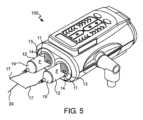
図1を参照すると、一実施形態による流体注入器システム100は、対向する側面104、遠位端または上端106、および近位端または下端108を有する注入器ハウジング102を含む。ハウジング102は、様々な機械的駆動コンポーネント、機械的駆動コンポーネントを駆動するために必要な電気および電力コンポーネント、ならびに本明細書に記載される流体注入器システム100に関連付けられた往復可動ピストン103(図示せず)の動作を制御するために使用される、電子メモリおよび電子制御装置などの制御コンポーネント(以下、1つまたは複数の電子制御装置)を包含する。このようなピストン103は、モータによって駆動されるボールねじシャフト、ボイスコイルアクチュエータ、ラックピニオン歯車駆動装置、リニアモータなどのような電気機械的駆動コンポーネントを介して、往復動作可能であり得る。いくつかの例では、機械的駆動コンポーネント、電気および電力コンポーネント、ならびに制御コンポーネントの少なくともいくつかは、ベース110上に提供され得る。 Referring to FIG. 1, a
引き続き図1を参照すると、流体注入器システム100は、MUDS、機械的駆動コンポーネント、電気および電力コンポーネント、ならびに制御コンポーネントの少なくとも一部を包含する少なくとも1つのドア116を有してもよい。 With continued reference to FIG. 1, the
流体注入器システム100は、少なくとも1つのバルク流体源120と接続するための少なくとも1つのバルク流体コネクタ118を含み得る。いくつかの例では、複数のバルク流体コネクタ118が提供されてもよい。たとえば、図1に示される流体注入器の実施形態に示されるように、3つのバルク流体コネクタ118が並んで、またはその他の配置で提供されてもよい。いくつかの例では、少なくとも1つのバルク流体コネクタ118は、バイアル、ボトル、またはバッグなど、少なくとも1つのバルク流体源120に取り外し可能に接続するように構成されたスパイクを含み得る。少なくとも1つのバルク流体コネクタ118は、本明細書に記載されるように、複数回使用使い捨てセット(「MUDS」)上に形成され得る。少なくとも1つのバルク流体源120は、流体注入器システム100によって患者に送達するために、生理食塩水、造影剤、またはその他の医療用流体などの医療用流体を受容するように構成され得る。
引き続き図1を参照すると、流体注入器システム100の実施形態は、グラフィカルユーザインターフェース(GUI)表示ウィンドウなどの1つ以上のユーザインターフェース124を含み得る。ユーザインターフェース124は、患者情報、プログラムされた注入プロトコル、注入状態または経過、現在の流量、流体圧力、および流体注入器システム100に接続された少なくとも1つのバルク流体源120内に残っている量など、流体注入器システム100に伴う流体注入処置に関する情報を表示することができ、オペレータが流体注入器システム100の動作のためのコマンドおよび/またはデータを入力すること、ならびに遠隔入力ステーションまたはディスプレイからオペレータコマンドを受信することを可能にするタッチスクリーンGUIであってもよい。ユーザインターフェース124は注入器ハウジング102上に示されているが、このようなユーザインターフェース124はまた、たとえばx線への曝露からユーザを保護するように設計された遠隔室などで、流体注入器システム100のハウジング102ならびに制御および機械的要素に有線または無線接続された遠隔ディスプレイの形態であってもよく、または流体注入器システム100がこれを追加で有してもよい。いくつかの例では、ユーザインターフェース124は、ハウジング102に取り外し可能に接続され、ハウジング102と有線または無線で通信接続された、タブレットコンピュータであってもよい。加えて、流体注入器システム100および/またはユーザインターフェース124は、流体注入器システム100のその場にいるオペレータによる触覚操作のための少なくとも1つの制御ボタン126を含み得る。特定の例では、少なくとも1つの制御ボタン126は、オペレータによってコマンドおよび/またはデータを入力するためのキーボードの一部であり得る。少なくとも1つの制御ボタン126は、1つまたは複数の電子制御装置への直接入力を提供するために、流体注入器システム100に関連付けられた1つまたは複数の電子制御装置と結線接続されてもよい。少なくとも1つの制御ボタン126はまた、タッチスクリーンなどのユーザインターフェース124のグラフィカル部分であってもよい。いずれの配置でも、少なくとも1つの制御ボタン126は、望ましくは、(1)多患者使い捨てセットが挿抜され
ていることを通知する、(2)注入プロトコルを選択またはプログラムする、(3)流体注入器システム100の充填/パージ、(4)患者および/または注入処置に関する情報および/またはデータを入力する、(5)流体注入器システム100をプリロードする、および(6)注入処置を開始/停止するなどの、ただしこれらに限定されない、特定の個々の制御機能を流体注入器システム100のその場にいるオペレータに提供する。ユーザインターフェース124および/または流体注入器システム100に関連付けられた任意の電子処理ユニットは、病院ネットワークシステムなどの動作および/またはデータ記憶システムに有線または無線で接続され得る。 With continued reference to FIG. 1, embodiments of
図2を参照すると、図1に示される流体注入器システム100の実施形態は、1つ以上のバルク流体源120から患者に1つ以上の流体を送達するための流体注入器システム100に取り外し可能に接続されたMUDS130を含む。MUDSの実施形態の例および特徴は、2016年1月7日に出願された国際公開第2016/112163号パンフレットにさらに記載されており、その開示は参照によりその全体が本明細書に組み込まれる。MUDS130は、1つ以上のシリンジなどの1つ以上の流体リザーバ132を含み得る。本明細書で使用される際に、用語「流体リザーバ」は、たとえばシリンジ、ローリングダイヤフラム、ポンプ、圧縮バッグなどを含む、たとえば流体注入処置中に流体を取り入れて送達することが可能な任意の容器を意味する。流体リザーバは、システムが閉鎖されるかまたは流体経路の残部から流体的に隔離された後に流体リザーバと流体連通したままとなる流体経路の部分を含む、流体リザーバの内部と流体連通している、1つ以上のチューブ長などの流体経路の少なくとも一部の内部容積を含み得る。いくつかの例では、流体リザーバ132の数は、バルク流体源120の数に対応し得る。たとえば、図2を参照すると、MUDS130は、各シリンジ132が対応する3つのバルク流体源120のうちの1つ以上と流体的に接続可能なように、並んだ配置の3つのシリンジ132を有する。いくつかの例では、1つ以上のバルク流体源120がMUDS130の1つ以上のシリンジ132に接続されてもよい。各シリンジ132は、対応するバルク流体コネクタ118および関連するMUDS流体経路134によって、バルク流体源120の1つと流体的に接続可能であってもよい。MUDS流体経路134は、バルク流体コネクタ118および流体入口ライン150に接続するスパイク要素を有してもよい。いくつかの例では、バルク流体コネクタ118は、MUDS130上に直接提供されてもよい。 Referring to FIG. 2, the embodiment of the
図2をさらに参照すると、MUDS130は、流体注入器システム100のハウジング102に取り外し可能に接続可能である。当業者によって理解されるように、流体注入器システム100との流体接続が確立されたこと、または流体リザーバから空気が除去されたことの視覚的検証を容易にするために、透明な医療グレードのプラスチックからMUDS130の少なくとも一部を構築することが望ましいだろう。視覚的検証は、一般に、たとえば、本明細書に記載されるような空気除去プロトコルを実行した後に、様々な流体接続内に気泡が存在しないことを確認するためにも望ましい。プライミング動作中に流体ラインまたは流体リザーバのいずれかで空気を検出するために、様々な光学センサ(図示せず)も提供され得る。 With further reference to FIG. 2,
引き続き図2を参照すると、MUDS130は、どの医療用流体または医療用流体の組み合わせが複数回投与量バルク流体源120(図1参照)から流体リザーバ132に引き込まれ、および/または各流体リザーバ132から患者に送達されるかを制御するための、活栓弁などの1つ以上の弁136を含み得る。いくつかの例では、1つ以上の弁136は、複数のシリンジ132の遠位端、またはマニホールド148上に提供され得る。マニホールド148は、シリンジ132の内部容積と弁136を介して選択的に流体連通し得る。シリンジ132の内部容積は、弁136を介して、各シリンジ132を対応するバルク流体源120に接続するMUDS流体経路134の第1の端部と選択的に流体連通し得る。MUDS流体経路134の対向する第2の端部は、バルク流体源120と流体的に接続するように構成されたそれぞれのバルク流体コネクタ118に接続され得る。1つ以上の弁136の位置に応じて、流体は1つ以上のシリンジ132の内部容積に引き込まれてもよく、またはこれは1つ以上のシリンジ132の内部容積から送達されてもよい。シリンジ132の充填中など、第1の位置では、1つ以上の弁136は、流体が、MUDS流体経路などの流体入口ライン150を通じてバルク流体源120から所望のシリンジ132内に流れるように、配向されている。充填処置中、1つ以上の弁136は、1つ以上の流体出口ライン152またはマニホールド148を通る流体流が遮断または閉鎖されるように配置されている。流体送達処置中など、第2の位置では、1つ以上のシリンジ132からの流体は、1つ以上の流体出口ライン152またはシリンジ弁出口ポートを通じてマニホールド148に送達される。送達処置中、1つ以上の弁136は、1つ以上の流体入口ライン150を通る流体流が遮断または閉鎖されるように配置されている。第3の位置では、1つ以上の弁136は、1つ以上の流体入口ライン150および1つ以上の流体出口ライン152またはマニホールド148を通る流体流が遮断または閉鎖されるように配向されている。したがって、第3の位置では、1つ以上の弁136の各々は、対応するシリンジ132を隔離し、対応するシリンジ132の内部容積に出入りする流体流を防止する。このように、1つ以上のシリンジ132および対応する弁136の各々が、閉鎖形を画定する。 With continued reference to FIG. 2, the
1つ以上の弁136、流体入口ライン150、および/または流体出口ライン152は、マニホールド148に統合されるか、またはこれを介して流体連通してもよい。1つ以上の弁136は、手動または自動操作によって第1または第2の位置に選択的に配置され得る。たとえば、オペレータは、1つ以上の弁136を、充填、流体送達のための所望の位置、または閉位置に配置し得る。別の例では、流体注入器システム100の少なくとも一部は、オペレータによる、またはシステムコントローラ内のプロトコルによる入力に基づいて、1つ以上の弁136を、充填、流体送達のための所望の位置、または閉位置に配置するように動作可能である。 One or
流体注入器システム100およびMUDS130のコンポーネントについて一般的に記載してきたが、単回使用使い捨てセット190(SUDS)の構造および使用方法ならびにMUDS130との相互作用が、以下に記載される。 Having generally described the components of
図3を参照すると、記載される実施形態によれば、流体注入器システム100は、SUDS190の少なくとも一部との解放可能な流体接続を形成するように構成された接続ポート192を有する。いくつかの例では、接続ポート192は、MUDS130上に形成されてもよい。本明細書に記載されるように、SUDS190は、MUDS130および/またはハウジング102の少なくとも一部に形成された接続ポート192に接続され得る。望ましくは、SUDS190と接続ポート192との間の接続は、SUDS190を選択的に接続ポート192から切断させ、接続ポート192に接続させる、解放可能な接続である。いくつかの例では、SUDS190は、接続ポート192から切断され、各流体送達処置の後に廃棄されてもよく、新しいSUDS190が後続の流体送達処置のために接続ポート192に接続されてもよい。SUDS190は、SUDS190の本体から選択的に切り離されて患者のカテーテルに接続され得る遠位端を有するSUDS流体ライン208によって、1つ以上の医療用流体を患者に送達するために使用され得る。SUDS190の別の例および特徴は、2016年7月7日に出願された、米国特許公開第2016/0331951号明細書に記載されており、その開示は、参照により本明細書に組み込まれる。 Referring to FIG. 3, according to the described embodiment,
図4を参照すると、電子制御装置900は、流体注入器100の充填および送達動作を制御するために、流体注入器システム100に関連付けられてもよい。いくつかの例では、電子制御装置900は、所望のガス/空気除去、充填、および/または送達処置に作用するために、様々な弁、活栓、ピストン部材、およびその他の要素の動作を制御し得る。たとえば、電子制御装置900は、様々な個別のコンピュータ可読媒体コンポーネントを含み得る。たとえば、このコンピュータ可読媒体は、揮発性媒体、不揮発性媒体、リムーバブル媒体、非リムーバブル媒体、一時的媒体、非一時的媒体などのような、電子制御装置900によってアクセス可能な任意の媒体を含み得る。さらなる例として、このコンピュータ可読媒体は、コンピュータ可読命令、データ構造、プログラムモジュール、または他のデータ;ランダムアクセスメモリ(RAM)、読み取り専用メモリ(ROM)、電子的消去可能プログラマブル読み取り専用メモリ(EEPROM)、フラッシュメモリ、クラウド記憶媒体、または他のメモリ技術;ソリッドステートメモリ、クラウドメモリ、CD-ROM、デジタル多用途ディスク(DVD)、または他の光ディスクストレージ;磁気カセット、磁気テープ、磁気ディスクストレージ、または他の磁気記憶装置;または所望の情報を記憶するために使用することができ、電子制御装置900によってアクセス可能な、他の任意の媒体など、情報の記憶のための任意の方法または技術で実装される媒体などのコンピュータ記憶媒体を含み得る。さらに、このコンピュータ可読媒体は、搬送波または他の輸送機構などの変調データ信号中のコンピュータ可読命令、データ構造、プログラムモジュール、または他のデータなどの通信媒体を含み得、任意の情報配信媒体、有線媒体(有線ネットワークおよび直接優先接続など)、および無線媒体(音響信号、無線周波数信号、光信号、赤外線信号、生体信号、バーコード信号など)を含み得る。当然ながら、上記のいずれの組み合わせも、コンピュータ可読媒体の範囲に含まれるべきである。 Referring to FIG. 4, an electronic controller 900 may be associated with the
電子制御装置900は、ROMおよびRAMなどの揮発性および不揮発性メモリの形態のコンピュータ記憶媒体を有するシステムメモリ908をさらに含む。適切なコンピュータベースのルーチンを有する基本入出力システム(BIOS)は、典型的には、電子制御装置900内のコンポーネント間の情報の転送を支援し、通常はROM内に記憶されている。システムメモリ908のRAM部分は、プロセッサ904に直ちにアクセス可能であるかまたはこれにより現在動作されているデータおよびプログラムモジュール、たとえばオペレーティングシステム、アプリケーションプログラミングインターフェース、アプリケーションプログラム、プログラムモジュール、プログラムデータ、およびその他の命令ベースのコンピュータ可読コードを包含する。 Electronic controller 900 further includes system memory 908 having computer storage media in the form of volatile and non-volatile memory such as ROM and RAM. A basic input/output system (BIOS), with appropriate computer-based routines, typically facilitates the transfer of information between components within electronic control unit 900 and is usually stored in ROM. The RAM portion of system memory 908 stores data and program modules that are immediately accessible to or currently being operated on by processor 904, such as an operating system, application programming interfaces, application programs, program modules, program data, and other Contains instruction-based computer readable code.
引き続き図4を参照すると、電子制御装置900はまた、他のリムーバブルまたは非リムーバブル、揮発性または不揮発性、一時的または非一時的なコンピュータ記憶媒体製品を含み得る。たとえば、電子制御装置900は、ハードディスクドライブ912と通信してこれを制御する非リムーバブルメモリインターフェース910、たとえば非リムーバブル不揮発性磁気媒体;ならびに磁気ディスクドライブユニット916(リムーバブル不揮発性磁気ディスク918の読み取りおよび書き込みを行う)、光ディスクドライブユニット920(CD ROMなどのリムーバブル不揮発性光ディスク922の読み取りおよび書き込みを行う)、リムーバブルメモリカードとの接続で使用されるユニバーサルシリアルバス(USB)ポート921などと通信してこれらを制御するリムーバブル不揮発性メモリインターフェース914を含み得る。しかしながら、磁気テープカセットおよびフロッピーディスク、CD、DVD、デジタルビデオテープ、ソリッドステートRAM、ソリッドステートROM、クラウドメモリなどを含むがこれらに限定されない例示的な計算システム環境902において、他のリムーバブルまたは非リムーバブル、揮発性または不揮発性コンピュータ記憶媒体が使用され得ることが想定される。これらの様々なリムーバブルまたは非リムーバブル、揮発性または不揮発性磁気媒体は、システムバス906を介して、プロセッサ904および電子制御装置900の他のコンポーネントと通信している。上記で論じられ、図4に示される、ドライブおよびこれらの関連するコンピュータ記憶媒体は、電子制御装置900のオペレーティングシステム、コンピュータ可読命令、アプリケーションプログラム、データ構造、プログラムモジュール、プログラムデータ、およびその他の命令ベースのコンピュータ可読コードのストレージを提供する(システムメモリ908内のこの情報およびデータの複製であるか否かにかかわらず)。 With continued reference to FIG. 4, electronic controller 900 may also include other removable or non-removable, volatile or non-volatile, temporary or non-transitory computer storage media products. For example, the electronic controller 900 includes a non-removable memory interface 910 that communicates with and controls a hard disk drive 912, such as non-removable non-volatile magnetic media; ), optical disk drive unit 920 (reads and writes to removable non-volatile optical disks 922 such as CD ROMs), and universal serial bus (USB) port 921 used for connection with removable memory cards. A removable non-volatile memory interface 914 may be included. However, other removable or non-removable devices may be used in the exemplary computing system environment 902, including but not limited to magnetic tape cassettes and floppy disks, CDs, DVDs, digital video tapes, solid state RAM, solid state ROM, cloud memory, etc. It is envisioned that volatile or non-volatile computer storage media may be used. These various removable or non-removable, volatile or non-volatile magnetic media communicate with processor 904 and other components of electronic control unit 900 via system bus 906. The drives and their associated computer storage media, discussed above and illustrated in FIG. provides storage of computer-readable code based on the system memory 908 (whether or not a copy of this information and data within system memory 908).
ユーザは、ユーザ入力インターフェース928を介して図1に示されるユーザインターフェース124になど、特定の取り付け可能または操作可能な入力装置を通じて電子制御装置900にコマンド、情報、およびデータを入力し得る。外部の供給源から電子制御装置900へのデータおよび情報の入力を容易にする任意の配置を含む、たとえばマイクロフォン、トラックボール、ジョイスティック、タッチパッド、タッチスクリーン、スキャナなど、様々なこのような入力装置が利用され得る。前述のように、これらおよびその他の入力装置は、システムバス906に結合されたユーザ入力インターフェース928を通じてプロセッサ904に接続されることが多いが、パラレルポート、ゲームポート、またはUSBなど他のインターフェースまたはバス構造によって接続されてもよい。さらにまた、データおよび情報は、モニタ930(この情報およびデータを電子的な形態で視覚的に表示するため)、プリンタ932(この情報およびデータを印刷形態で物理的に表示するため)、スピーカ934(この情報およびデータを可聴形態で音声により提示するため)などの特定の出力装置を通じて、わかりやすい形態または形式でユーザに提示または提供され得る。これらの装置のすべては、システムバス906に結合された出力インターフェース936を通じて電子制御装置900と通信している。このような周辺出力装置はいずれも、情報およびデータをユーザに提供するために使用されることが想定される。 A user may enter commands, information, and data into electronic control unit 900 through certain attachable or operable input devices, such as into
電子制御装置900は、電子制御装置900と一体であるかまたはそこから離れている通信装置940の使用を通じて、ネットワーク環境938で動作し得る。この通信装置940は、通信インターフェース942を通じて、電子制御装置900の他のコンポーネントによって動作可能であり、これらと通信している。このような配置を使用して、電子制御装置900は、パーソナルコンピュータ、サーバ、ルータ、ネットワークパーソナルコンピュータ、ピアデバイス、またはその他の一般的なネットワークノードであり得る、リモートコンピュータ944などの1つ以上のリモートコンピュータに接続されるかまたは別途これと通信してもよく、通常は、電子制御装置900に関連して上述されたコンポーネントの多くまたはすべてを含む。適切な通信装置940、たとえばモデム、ネットワークインターフェース、またはアダプタなどを使用して、コンピュータ944は、ローカルエリアネットワーク(LAN)および広域ネットワーク(WAN)内で動作し、これらを通じて通信し得るが、仮想プライベートネットワーク(VPN)、オフィスネットワーク、病院ネットワーク、エンタープライズネットワーク、イントラネット、インターネットなどのような他のネットワークも含み得る。 Electronic controller 900 may operate in a network environment 938 through the use of a communication device 940 that is integral to electronic controller 900 or separate therefrom. The communication device 940 is operable and in communication with other components of the electronic control unit 900 through a communication interface 942. Using such an arrangement, electronic control device 900 may be connected to one or more remote computers 944, which may be personal computers, servers, routers, network personal computers, peer devices, or other common network nodes. It may be connected to or otherwise communicate with a remote computer and typically includes many or all of the components described above in connection with electronic controller 900. Using suitable communications equipment 940, such as a modem, network interface, or adapter, computer 944 may operate within and communicate through local area networks (LANs) and wide area networks (WANs), but may also communicate through virtual private networks. Networks (VPNs), office networks, hospital networks, enterprise networks, intranets, the Internet, etc. may also be included.
本明細書で使用される際に、電子制御装置900は、本開示の方法およびシステムの処理ステップを実行および実装するために、適切なカスタム設計または従来のソフトウェアを含むかまたはこれを実行するように動作し、これにより、特殊な特定の計算システムを形成する。したがって、方法およびシステムは、本開示に関連して以下に論じられる方法、プロセス、および変換データ操作をプロセッサ904に実行、構成、または別途実装させるコンピュータ可読プログラムコードまたは命令を記憶することが可能なコンピュータ可読記憶媒体を有する、1つ以上の電子制御装置900または類似の計算装置を含み得る。さらにまた、電子制御装置900は、パーソナルコンピュータ、携帯情報端末、携帯コンピュータ、ラップトップ、タブレット、パームトップ、モバイルデバイス、携帯電話、サーバ、またはコンピュータ実装された方法およびシステムを効率的に実装するためデータを適切に処理するのに必要な処理ハードウェアおよびソフトウェアを有するその他いずれかのタイプの計算装置の形態であり得る。 As used herein, electronic controller 900 includes or is configured to include appropriate custom-designed or conventional software to perform and implement the processing steps of the disclosed methods and systems. , thereby forming a special and specific computing system. Accordingly, the methods and systems are capable of storing computer-readable program code or instructions that cause processor 904 to perform, configure, or otherwise implement the methods, processes, and transformation data operations discussed below in connection with this disclosure. It may include one or more electronic controllers 900 or similar computing devices with computer-readable storage media. Furthermore, the electronic controller 900 can be used to efficiently implement computer-implemented methods and systems such as a personal computer, personal digital assistant, mobile computer, laptop, tablet, palmtop, mobile device, cell phone, server, or computer-implemented method and system. It may take the form of any other type of computing device having the necessary processing hardware and software to properly process the data.
システムが、それぞれのサーバと同じであってもなくてもよい1つ以上のコンピュータ上に物理的に配置された、またはこれによりアクセス可能な、たとえばルックアップテーブルなどのデータベースを利用し得ることは、当業者にとって明らかであろう。たとえば、電子制御装置900上のプログラミングソフトウェアは、ネットワークの別個のプロセッサ上または別の方法で物理的に格納されたデータベースを制御し得る。 The system may utilize databases, such as lookup tables, physically located on or accessible by one or more computers, which may or may not be the same as the respective servers. , will be clear to those skilled in the art. For example, programming software on electronic controller 900 may control a database physically stored on a separate processor in the network or otherwise.
いくつかの例では、電子制御装置900は、様々な流体リザーバの各々の中の流体の圧力、流体リザーバの下流の流体導管内の圧力、流体リザーバの各々に侵入するときまたは出るときの各流体の流体流量、流体導管内の流体の流体流量、流体導管内の流体の逆流の存在、流体リザーバ内および/または流体導管内の流体の粘度、流体リザーバ内の流体の温度、様々な流体リザーバの各々のピストンまたはプランジャなどの駆動コンポーネントの速度、駆動コンポーネントのパルスシーケンスのパルス周波数および/または振幅、ならびにこれらの様々な組み合わせからなる群より選択された注入パラメータなど、注入プロトコル中に1つ以上の注入パラメータを測定および/または監視するようにプログラムされ得る。制御装置900は、流体注入システムに関連付けられた1つ以上のセンサと電気的および/または機械的に通信することにより、1つ以上の注入パラメータを測定し得る。測定および/または監視された注入パラメータに基づいて、制御装置900は、たとえば注入パラメータが所望の範囲外であるかまたは所望の範囲から外れる傾向があることをセンサが読み取った場合に、パラメータが調整されて所望の範囲に向かって、または所望の範囲内に戻るように、対応する動作を変更、調整、開始、または停止し得る。 In some examples, the electronic controller 900 controls the pressure of the fluid in each of the various fluid reservoirs, the pressure in the fluid conduit downstream of the fluid reservoirs, and the pressure of each fluid as it enters or exits each of the fluid reservoirs. the fluid flow rate of the fluid in the fluid conduit, the presence of fluid backflow in the fluid conduit, the viscosity of the fluid in the fluid reservoir and/or the fluid conduit, the temperature of the fluid in the fluid reservoir, the fluid flow rate of the fluid in the fluid conduit, the One or more injection parameters may be selected from the group consisting of the speed of each drive component, such as a piston or plunger, the pulse frequency and/or amplitude of the drive component pulse sequence, and various combinations thereof. It may be programmed to measure and/or monitor injection parameters. Controller 900 may measure one or more injection parameters by electrically and/or mechanically communicating with one or more sensors associated with the fluid injection system. Based on the measured and/or monitored infusion parameters, the controller 900 may adjust the parameters if, for example, a sensor reads that the infusion parameters are outside of or tending to fall outside of a desired range. The corresponding operation may be changed, adjusted, started, or stopped so as to move toward or back within the desired range.
図1から図3は、流体注入器システム100および関連するコンポーネントおよび構造の一例を示すが、本開示は、いずれか特定のタイプまたは種類の流体注入器システム100に限定されないことを、理解すべきである。ここで図5を参照すると、本開示による流体注入器システム100の別の非限定的な例は、シリンジ12などの少なくとも1つの流体リザーバと、少なくとも1つのプランジャ14に接続可能な少なくとも1つのピストン103(図示せず)と、流体制御モジュール(図示せず、制御装置900など)とを含む。少なくとも1つのシリンジ12は、一般に、シリンジポート13などのシステムの少なくとも1つのコンポーネントとインターフェースするように適合されている。流体注入器システム100は一般に、注入処置中に少なくとも1つの流体Fを患者に送達するように構成されている。流体注入器システム100は、造影剤、生理食塩水溶液、またはいずれか所望の医療用流体などの少なくとも1つの流体Fで満たされる、少なくとも1つのシリンジ12を解放可能に受容するように構成されている。システムは、いくつかのシリンジが並んでまたは他の空間的関係で配向されてもよく、注入器に関連付けられたそれぞれのピストンによって別個に作動される、マルチシリンジ注入器であってもよい。少なくとも1つのシリンジ12は、直立、まっすぐなどいずれの配向であってもよく、またはいずれの角度で配置されてもよい。別の実施形態では、流体注入器100は、1つ以上のローリングダイヤフラムシリンジ(図示せず)とインターフェースし得る。ローリングダイヤフラムシリンジベースの注入器の非限定的な例は、米国特許出願第15/305,285号明細書および米国特許出願第15/568,505号明細書、ならびに国際出願US2017/056747号明細書に記載されており、その開示は参照により本明細書に組み込まれる。 Although FIGS. 1-3 illustrate one example of a
引き続き図5を参照すると、注入器システム100は、少なくとも1つのピストン103(図示せず)などの駆動コンポーネントで少なくとも1つのシリンジ12のプランジャ14を駆動することによって少なくとも1つの医療用流体Fを患者の血管系に注入するために、医療処置中に使用され得る。少なくとも1つのピストンは、プランジャ14など、少なくとも1つのシリンジの少なくとも一部で往復動作可能であり得る。係合すると、少なくとも1つのピストンは、少なくとも1つのシリンジの遠位端19に向けてプランジャ14を動かし、ならびに少なくとも1つのシリンジ12の近位端11に向けてプランジャ14を後退させることができる。 Still referring to FIG. 5, the
チューブセット(たとえば、第1および第2流体導管17aおよび17b、ならびに共通の流体導管20)は、各シリンジ12から血管アクセス部位で患者に挿入されたカテーテル(図示せず)に流体Fを送達するためのカテーテルと流体連通して各シリンジを配置するために、各シリンジ12と流体連通し得る。第1および第2流体導管17aおよび17bは、当該技術分野で知られている任意の適切な機構(たとえば、YコネクタまたはTコネクタ)によって共通の流体導管20に接続され得る。特定の実施形態では、1つ以上のシリンジ12からの流体流は、注入流量、各シリンジ内の流体圧力、流体導管持続時間内の流体流量、および総注入量などのユーザ選択注入パラメータに基づいて、患者への少なくとも1つの流体の送達を調節するために様々な駆動コンポーネント、弁、活栓、および流れ調節構造を動作させる、電子制御装置900と同じかまたは類似であり得る流体制御モジュールによって、調節され得る。流体制御モジュールは一般に、様々な機能を実行するように構成されており、これらは、他の様々な実施形態と併せて本明細書に記載されるように、システムのシリンジからシリンジへの流体の逆流の防止を支援する能力を有する。 A tube set (e.g., first and second fluid conduits 17a and 17b and a common fluid conduit 20) delivers fluid F from each
いくつかの例では、流体制御モジュールは、少なくとも1つのシリンジ12を少なくとも1つの流体Fで満たすように、流体注入器システム100に指示し得る。流体注入器システム100は、シリンジ12の各々を所望の流体で満たすために、それぞれがシリンジ12の各々に対する、複数のバルク流体源、たとえばバルク造影流体供給源およびバルク生理食塩水供給源を有してもよい。少なくとも1つのシリンジ12を少なくとも1つの流体Fで満たすステップは、少なくとも1つのシリンジ12を少なくとも1つのバルク流体源と流体連通して配置し、少なくとも1つのシリンジ12のプランジャ14に取り外し可能に係合されているピストンを、少なくとも1つのシリンジの遠位端19から少なくとも1つのシリンジの近位端11に向かって後退させるように、流体注入器システム100に指示することによって、行われ得る。特定の実施形態では、流体注入器システム100および流体制御モジュールは、空気除去プロトコルを実行するようにプログラムされ得る。図5に示されるように、流体注入器システム100は開放システムであってもよく、すなわち2つのシリンジ12が、いかなる中間弁または活栓も用いることなく共通の流体導管20に接続する第1および第2流体導管17aおよび17bと流体接続し得る。このような開放システムでは、第2のシリンジ内の流体圧力に対する第1のシリンジ内の流体圧力の差が、高圧シリンジから低圧シリンジ内への流体の逆流をもたらす可能性がある。このような状況、たとえば高圧の造影流体が低圧の生理食塩水シリンジに流入する状況は、たとえば、送達される流体量の不正確さ、イメージング法から最適な画像が得られない、および医療用流体の浪費などの結果をもたらす可能性がある。別の実施形態によれば、流体注入器システム100は、たとえば、シリンジ12および/または第1および第2流体導管17aおよび17bの各々の遠位端19が第1および第2流体導管17aおよび17bの他方ならびに別のシリンジ12から各シリンジの内部を流体的に隔離するための1つ以上の弁または活栓を含み得る、閉鎖系であってもよい。 In some examples, the fluid control module may direct the
造影流体および生理食塩水フラッシング流体など、2つ以上の流体タイプを送達するように設定された、本明細書で説明および図示されるような2つ以上のシリンジを有する流体注入器システムなどのマルチリザーバ消耗品を有する注入器システムでは、異なるリザーバ内での2つの流体の意図しない混合の防止が望まれる。使い捨てリザーバの使用寿命にわたって複数の患者のために1つまたは複数の同じリザーバが使用される複数患者用途において、これは特に適切であろう。たとえば生理食塩水リザーバへの造影剤の意図しない混合は、テスト注入またはフラッシュフェーズ中の意図しない患者への投与もたらす可能性がある。逆に、造影剤リザーバ内への生理食塩水の意図しない混合は、希釈された投与をもたらし、診断に適さない、または低品質の画像を生成する可能性がある。 Multi-fluid injector systems, such as those having two or more syringes as described and illustrated herein, configured to deliver two or more fluid types, such as contrast fluid and saline flushing fluid. In syringe systems with reservoir consumables, it is desirable to prevent unintentional mixing of two fluids in different reservoirs. This may be particularly appropriate in multi-patient applications where the same reservoir or reservoirs are used for multiple patients over the lifetime of the disposable reservoir. For example, unintentional mixing of contrast agent into the saline reservoir can result in unintended patient administration during the test injection or flush phase. Conversely, unintentional mixing of saline into the contrast agent reservoir can result in diluted administration and produce images that are unsuitable for diagnosis or of poor quality.
特定の注入器では、消耗品の配向は、使用期間中に固定され得る。たとえば、一部の注入器では、リザーバは、常にリザーバの遠位出口を上に向けて配向されている。このようなリザーバ設定では、任意の流体混合は、リザーバの上部から侵入し、占有流体に向かって下方に続く、より密度の高い流体を伴う。造影剤と生理食塩水との相対密度を考えると、これは、造影剤が生理食塩水リザーバに侵入する場合、底に沈むであろうことを意味している。造影剤は、垂直設定のリザーバの底部で固まるので、リザーバから送達される最後の流体となる。生理食塩水リザーバへの造影剤の流入を繰り返すことで、注入ごとの生理食塩水リザーバ内の造影剤パーセンテージを増加させ続けるだろう。生理食塩水を造影剤リザーバに混入することは、逆の効果をもたらす。より軽い生理食塩水流体は、造影剤リザーバの上部に閉じ込められたままとなり、侵入時の流体の速度に応じて、ほんの一部のみが占有造影剤の中に分散する。その結果、生理食塩水は、次の造影剤フェーズの開始時に吸出され、時間とともに混合繰り返しの影響を最小化するが、不正確な投与量の造影剤が患者に投与される結果となる。図5に示される注入器のような、別の実施形態によれば、流体注入器ヘッドは、シリンジの遠位端が概して下向きの方向を指すに旋回し得る。この実施形態では、生理食塩水シリンジ内へのより密度の高い造影剤の逆流の結果、造影剤がシリンジの遠位先端に溜まるので、流体注入器が生理食塩水を注入するようにプログラムされているとき、遠位先端の造影剤が最初に注入され、造影剤の過剰投与および浪費をもたらし、得られた画像の品質に影響を及ぼす。造影剤シリンジ内への生理食塩水の逆流により、プランジャに近いシリンジの近位端に生理食塩水が溜まり、これは、造影剤シリンジがその中に少量の流体を有するときに投与された造影剤投与量を希釈して、得られた画像の品質に影響を及ぼす。 For certain syringes, the orientation of the consumable may be fixed during use. For example, in some syringes, the reservoir is always oriented with the distal outlet of the reservoir facing upward. In such a reservoir setup, any fluid mixing will be with the denser fluid entering from the top of the reservoir and continuing downward toward the occupying fluid. Given the relative density of the contrast agent and saline, this means that if the contrast agent were to enter the saline reservoir, it would sink to the bottom. The contrast agent solidifies at the bottom of the reservoir in a vertical setting and is therefore the last fluid delivered from the reservoir. Repeated flow of contrast into the saline reservoir will continue to increase the percentage of contrast in the saline reservoir with each injection. Incorporating saline into the contrast agent reservoir has the opposite effect. The lighter saline fluid remains trapped at the top of the contrast agent reservoir and, depending on the velocity of the fluid upon entry, only a small portion will disperse into the occupied contrast agent. As a result, the saline is aspirated at the beginning of the next contrast phase, minimizing the effects of repeated mixing over time, but resulting in inaccurate doses of contrast being administered to the patient. According to another embodiment, such as the injector shown in FIG. 5, the fluid injector head can be pivoted such that the distal end of the syringe points in a generally downward direction. In this embodiment, the fluid injector is programmed to inject saline because backflow of the denser contrast into the saline syringe causes the contrast to accumulate at the distal tip of the syringe. When the distal tip contrast agent is injected first, resulting in overdosage and waste of contrast agent, affecting the quality of the obtained images. The backflow of saline into the contrast syringe causes saline to accumulate at the proximal end of the syringe near the plunger, which is associated with contrast media being administered when the contrast syringe has a small amount of fluid in it. Dilute the dose and affect the quality of the images obtained.
リザーバ間の混合の原因は、高圧流体が低圧流体の流れに逆らって上流に移動する逆流として識別される現象による。逆流は、少なくとも部分的に、圧力勾配の物理学に基づいている。基礎となる原理は、減圧方向に流れが発生すること、たとえば最高圧力点から最低圧力点に向かって流れが伝播することである。特定の消耗品では、この経路は、注入リザーバから、患者のチューブセットに移動し、カテーテルから出る傾向がある。リザーバ内の圧力は駆動コンポーネントによる流体の変位によって生成されるので、リザーバは最高圧力点にある。圧力の大きさは、流体粘度、流量、負荷がかかった注入器コンポーネントの機械的たるみ、流体圧力下のシリンジおよびチューブ材料の膨張、ならびに下流のインピーダンス(たとえば、非限定的に、シリンジ出口のID、カテーテルパージおよびチューブセットID)に依存する。2つのリザーバが同時に開放している場合、2つのリザーバ間で圧力が異なっていれば逆流のリスクがある。最も低い圧力を有するリザーバは、接続チューブセットを通る逆流を介した高圧流体の導入の影響を受けやすくなる。このメカニズムを介した逆流は、システムの機械的コンポーネントに対する圧力および付加の増加とともにその体積が増大するリザーバの適応しやすい性質によっても発生または悪化する可能性がある。前述のように、流体の意図しない混合のリスクは、3つのリザーバのうちの少なくとも2つがマニホールドの患者ラインに対して開放しているときにのみ存在する。 The cause of mixing between reservoirs is due to a phenomenon identified as counterflow, where high pressure fluid moves upstream against the flow of low pressure fluid. Backflow is based, at least in part, on the physics of pressure gradients. The underlying principle is that flow occurs in the direction of reduced pressure, eg, flow propagates from the highest pressure point towards the lowest pressure point. For certain consumables, this path tends to travel from the infusion reservoir to the patient's tubing set and out the catheter. Since the pressure in the reservoir is generated by the displacement of the fluid by the drive component, the reservoir is at the highest pressure point. The magnitude of the pressure is dependent on fluid viscosity, flow rate, mechanical sag of syringe components under load, expansion of the syringe and tubing material under fluid pressure, and downstream impedance (for example, but not limited to, the ID of the syringe outlet). , catheter purge and tubing set ID). If two reservoirs are open at the same time, there is a risk of backflow if the pressures between the two reservoirs are different. The reservoir with the lowest pressure will be susceptible to the introduction of high pressure fluid via backflow through the connecting tube set. Backflow through this mechanism can also be caused or exacerbated by the malleable nature of the reservoir, whose volume increases with increasing pressure and loading on the mechanical components of the system. As previously mentioned, the risk of unintentional mixing of fluids exists only when at least two of the three reservoirs are open to the patient line of the manifold.
図6Aは、造影剤などの第1流体1002、および生理食塩水などの第2流体1004の、圧力対時間を示すグラフ1000であり、第1および第2流体1002、1004は、時間とともに同じ圧力を発生する。流体注入器システムが圧力プロファイルにしたがって流体を送達するとき、第1または第2流体1002、1004の一方が第1または第2流体1002、1004の他方を含むリザーバ内に逆流する可能性は、比較的低い、および/またはゼロであることが理解されるだろう。逆に、図6Bは、造影剤などの第1流体1012、および生理食塩水などの第2流体1014の、圧力対時間を示すグラフ1010であり、第1および第2流体1012、1014は、時間とともに異なる圧力を発生する。図6Bに示されるような圧力プロファイルを有する流体注入器システムでは、リザーバ間に圧力差ΔPがある間、高圧造影剤リザーバから低圧生理食塩水への望ましくない逆流が発生することが知られている。これは、従来技術の流体注入器システム1100の一部を示す図7に最も明確に示されている。図示されるように、低圧第1流体、たとえば生理食塩水1110は第1流体リザーバ1112内に収容され、第2流体、たとえば造影剤1114は第2流体リザーバ1116内に収容される。加えて、図示されるように、流体導管1101は、第1および第2流体リザーバ1112、1116の両方が開放しており、同時に造影剤と生理食塩水の特定の比率の混合物が患者ラインに流れる、デュアルフローとして知られる状況の間に、第1および第2流体リザーバ1112、1116の間に流体経路を提供し得る。図7に示されるように、たとえば造影剤1114が圧力曲線1012に対応し、生理食塩水1110が圧力曲線1014に対応する図6Bを参照する、第1および第2流体リザーバ1112、1116間の圧力差プロファイルのため、第2流体リザーバ1116からの造影剤1114は、不必要に「逆流」し、第1流体リザーバ1112に侵入している。 FIG. 6A is a graph 1000 showing pressure versus time for a first fluid 1002, such as a contrast agent, and a second fluid 1004, such as saline, where the first and second fluids 1002, 1004 have the same pressure over time. occurs. When a fluid injector system delivers fluid according to a pressure profile, the likelihood that one of the first or second fluids 1002, 1004 will flow back into the reservoir containing the other of the first or second fluids 1002, 1004 is relatively low. It will be appreciated that the target is low and/or zero. Conversely, FIG. 6B is a graph 1010 showing pressure versus time for a first fluid 1012, such as a contrast agent, and a second fluid 1014, such as saline, where the first and second fluids 1012, 1014 are and generate different pressures. It is known that in fluid injector systems with pressure profiles such as those shown in Figure 6B, undesirable backflow from the high-pressure contrast reservoir to the low-pressure saline occurs while there is a pressure difference ΔP between the reservoirs. . This is most clearly shown in FIG. 7, which shows a portion of a prior art
デュアルフローフェーズは、たとえば、1%造影剤/99%生理食塩水から99%造影剤/1%生理食塩水までの体積比でプログラムされることが可能である。そのため、第1の生理食塩水リザーバと第2の造影剤流体リザーバとの間に発生し得る、広範囲の圧力勾配がある。特定の流れ条件によれば、逆流は、密度差によって造影剤が底部に沈んで時間とともに蓄積するので、生理食塩水リザーバ内に混合する造影剤として識別され得る。特定の実施形態では、造影剤流量が生理食塩水流量よりもはるかに多く、したがって生理食塩水リザーバに対して造影剤リザーバの方が大きい圧力差を生じるので、デュアルフロー比がデュアルフローフェーズで95%から99%造影剤対5%から1%生理食塩水であるとき、このタイプの混合シナリオは一般的である。 Dual flow phases can be programmed, for example, with volume ratios from 1% contrast agent/99% saline to 99% contrast agent/1% saline. As such, there is a wide range of pressure gradients that can develop between the first saline reservoir and the second contrast fluid reservoir. Depending on the specific flow conditions, backflow can be identified as contrast agent mixing into the saline reservoir as the density difference causes the contrast agent to sink to the bottom and accumulate over time. In certain embodiments, the dual flow ratio is 95 in the dual flow phase because the contrast agent flow rate is much higher than the saline flow rate, thus creating a larger pressure difference in the contrast agent reservoir relative to the saline reservoir. This type of mixing scenario is common when it is 5% to 1% saline versus 99% contrast agent.
様々な実施形態によれば、デュアルフローフェーズは、注入の最初にプログラムされたフェーズであり得るか、もしくは造影剤フェーズ、生理食塩水フェーズ、異なるデュアルフローフェーズ、または遅延フェーズに続くことができる。特定の実施形態では、プログラムされたプロトコルシーケンスは、造影剤フェーズ、次にデュアルフローフェーズ、続いて生理食塩水フェーズであってもよい。この場合、造影剤リザーバは、造影剤フェーズで注入し、何らかの定常状態圧力を生成する。デュアルフローフェーズが始まると、生理食塩水リザーバが開放し、生理食塩水流が開始されると圧力を上昇させ始める。生理食塩水リザーバ内の圧力を上昇させることは、流体を加圧するように駆動コンポーネントを動かすこと、ならびに適応性の取り込みおよび機械的たるみの取り込みによるリザーバの体積膨張を補償することを含み得る。しかしながら、大気圧または造影剤フェーズよりも低い圧力の間に生理食塩水圧力が出口ラインまで開放し、前に生成されたフェーズ圧力などから造影剤の圧力が高い場合、生理食塩水リザーバが定常状態圧力まで上昇している間に、流体導管を通って生理食塩水リザーバ内への逆流が発生する可能性がある。これを防止するためのアプローチの1つは、たとえば、造影剤フェーズの終了時およびデュアルフローフェーズの開始時に、生理食塩水リザーバ内の圧力が造影剤の圧力と実質的に等しいことを保証するために、生理食塩水リザーバを与圧することによる、圧力均等化を使用することである。生理食塩水は、デュアルフローフェーズ中に造影剤を希釈するので、造影剤/生理食塩水混合物の粘度の低下により、システム内の圧力は造影剤に対して低下し、逆流を駆動する圧力のデルタはなくなる。 According to various embodiments, the dual flow phase can be the first programmed phase of the injection or can be followed by a contrast agent phase, a saline phase, a different dual flow phase, or a delay phase. In certain embodiments, the programmed protocol sequence may be a contrast phase, then a dual flow phase, then a saline phase. In this case, the contrast agent reservoir is injected in the contrast agent phase to create some steady state pressure. When the dual flow phase begins, the saline reservoir opens and begins to build up pressure as saline flow begins. Increasing the pressure within the saline reservoir may include moving a drive component to pressurize the fluid and compensating for volumetric expansion of the reservoir due to adaptive intake and mechanical slack intake. However, if the saline pressure is released to the exit line during atmospheric pressure or a pressure lower than the contrast agent phase, and the contrast agent pressure is higher, such as from a previously generated phase pressure, the saline reservoir is in steady state. During the build-up to pressure, backflow through the fluid conduit and into the saline reservoir may occur. One approach to prevent this is to ensure that the pressure in the saline reservoir is substantially equal to the pressure of the contrast agent, e.g. at the end of the contrast agent phase and at the beginning of the dual flow phase. Another option is to use pressure equalization by pressurizing the saline reservoir. Since the saline dilutes the contrast agent during the dual flow phase, the reduced viscosity of the contrast agent/saline mixture causes the pressure in the system to decrease relative to the contrast agent, reducing the delta in pressure that drives backflow. will disappear.
特定の実施形では、デュアルフローフェーズが注入の最初にプログラムされたフェーズであるか、または生理食塩水フェーズ、遅延フェーズ、または20mL未満の体積の造影剤フェーズに続く場合、生理食塩水は、造影剤圧力を圧力等化するのに十分な時間を有していない場合がある。したがって、生理食塩水よりも速く造影剤圧力が上昇するリスクの可能性があり、逆流を防止するために追加の論理が実装されなければならない。これらの実施形態では、逆流を防止する1つの方法は、定常状態までの圧力の一時的上昇の間、生理食塩水圧力が造影剤よりも高いことを保証することである。しかしながら、造影剤ピストンは生理食塩水ピストンよりも速く流体を送達するので、50%造影剤を超えるデュアルフロー比でより高い生理食塩水圧力を保証することは困難である。別のアプローチは、乱流頭を通過して生理食塩水シリンジ内への造影剤の流れを防止するために流体導管内に乱流頭界面を作製するために、生理食塩水駆動コンポーネントのパルスを使用することであり得る。 In certain embodiments, if the dual flow phase is the first programmed phase of the injection or follows a saline phase, a delayed phase, or a contrast phase with a volume of less than 20 mL, the saline There may not be enough time to equalize the agent pressure. Therefore, there is a potential risk of contrast agent pressure increasing faster than saline, and additional logic must be implemented to prevent reflux. In these embodiments, one way to prevent reflux is to ensure that the saline pressure is higher than the contrast agent during the temporary increase in pressure to steady state. However, since the contrast piston delivers fluid faster than the saline piston, it is difficult to guarantee higher saline pressures with dual flow ratios above 50% contrast. Another approach involves pulsing the saline-driven component to create a turbulent head interface within the fluid conduit to prevent the flow of contrast agent through the turbulent head and into the saline syringe. It can be done by using
本開示の様々な実施形態によれば、高圧リザーバと低圧リザーバとの間に観察されるこの逆流に対抗するために、本明細書でマイクロ圧力変動またはパルスと呼ばれる挙動が実施され得る。たとえば、開示された概念の様々な実施形態によれば、注入プロトコルを実行するように構成された改良型の流体注入器システム1200が、図8に部分的に示されている。図示されるように、流体注入器システム1200は、2つ以上の駆動コンポーネント1204、1205(図8に簡略化された形態で部分的に示される)の各々に動作可能に関連付けられた制御装置1202(簡略化された形態で示される)を含む。駆動コンポーネント1204、1205は、第1流体リザーバ1212から流体導管1201を通る第1流体(たとえば、非限定的に、生理食塩水1210)、および第2流体リザーバ1216から流体導管1201を通る少なくとも第2流体(たとえば、非限定的に、造影剤1214)を、加圧および注入するように構成されており、流体導管1201は、第1流体リザーバ1212および少なくとも第2流体リザーバ1216と選択的に流体連通している。制御装置1202は、流体導管1201を通る造影剤1214を加圧および注入するように第2駆動コンポーネント1205を作動させ、第2駆動コンポーネント1205が作動している間、流体導管1201を通る造影剤1214の第1流体リザーバ1210内への逆流を防止するために流体導管1201内の生理食塩水1210と造影剤1214との間の乱流頭界面1211を作製するために、生理食塩水1210の間欠パルスを導入するように第1駆動コンポーネント1204を作動させるようにプログラムまたは構成された、少なくとも1つのプロセッサ1203(図8に簡略化された形態で示される)を含む。言い換えると、流頭界面1211は、第1流体リザーバ1212内への造影剤1214の逆流を防止する、乱流を有する物理的な流体バリアとして作用する。 According to various embodiments of the present disclosure, a behavior referred to herein as micro-pressure fluctuations or pulses may be implemented to counter this observed backflow between the high-pressure and low-pressure reservoirs. For example, in accordance with various embodiments of the disclosed concepts, an improved fluid infuser system 1200 configured to perform an infusion protocol is shown in part in FIG. As illustrated, the fluid infuser system 1200 includes a controller 1202 operably associated with each of two or more drive components 1204, 1205 (shown partially in simplified form in FIG. 8). (shown in simplified form). The drive components 1204 , 1205 direct a first fluid (e.g., without limitation, saline 1210 ) through the
加えて、生理食塩水流量の一時的なパルス状増加は、第1流体リザーバ1210内に上昇圧力を生成し、少なくとも一時的に圧力勾配の大きさを減少させる。したがって、第1駆動コンポーネント1204が作動されると、第1流体リザーバ1210の容量が増加し(圧力下のリザーバの膨張による)、流体導管1201内の流頭界面1211を超える逆流から第1流体リザーバ1210内に造影剤1214が侵入しない間、第1流体の圧力が増加する。また、間欠パルスの送達の間、たとえば、パルス間隔(たとえば、パルス間の時間、パルス周波数)、パルス流量(たとえば、パルスの流量、パルス振幅)、およびパルス量(たとえば、パルスの有効持続時間)など少なくとも3つの制御され得るパラメータがあり得るが、これらは本明細書でより詳細に論じられる。 Additionally, the temporary pulsed increase in saline flow rate creates an increased pressure within the first fluid reservoir 1210, at least temporarily reducing the magnitude of the pressure gradient. Accordingly, when the first drive component 1204 is actuated, the capacity of the first fluid reservoir 1210 increases (due to expansion of the reservoir under pressure), causing backflow across the
図9は、流体注入器システム1200(図8)の動作期間中のモータ速度対時間のグラフ表示1300を示す。マイクロ圧力変動の実施は、デュアルフローフェーズ中のプログラムされた流量の生理食塩水1210を使用し、増加した流量の間欠パルスを導入することが、理解されるだろう。これらのパルスは、流頭界面1211で流体経路内の乱流を生成するとともに、逆流が発生するのを防止するために、急速な圧力を生成する。したがって、マイクロ圧力変動は、プログラムされた流量を取り、第1流体リザーバ1212内、ならびに特定の実施形態では圧力差による造影剤の逆流に対抗するために第1流体リザーバ1212に隣接する流体導管1201の一部で、乱流および高圧を生成するために、これを断続的に変化させる。たとえば、第1流体リザーバ1212の駆動コンポーネントの間欠パルスの結果として流体導管1201内の生理食塩水1210と造影剤1214との間の流頭界面1211を示す、図10の拡大図を参照されたい。 FIG. 9 shows a graphical representation 1300 of motor speed versus time during operation of fluid injector system 1200 (FIG. 8). It will be appreciated that the implementation of micro-pressure fluctuations uses saline 1210 at a programmed flow rate during the dual flow phase and introduces intermittent pulses of increased flow rate. These pulses create turbulence in the fluid path at the
再び図8を参照すると、プロセッサ1203は、生理食塩水1210の圧力が造影剤1214の圧力と実質的に同じ圧力に到達する(すなわち、第1のリザーバ1212と第2のリザーバ1216との間に圧力差がなくなる)まで生理食塩水1210の間欠パルスを導入し続けるように第1駆動コンポーネント1204を作動させ得ることが、理解されるだろう。1つの例示的な実施形態では、生理食塩水1210の圧力が造影剤1214の圧力と実質的に同じ圧力に到達する前に、40ミリリットル未満の生理食塩水1210が流体導管1201内に導入され得る。別の例示的な実施形態では、生理食塩水1210の圧力が造影剤1214の圧力と実質的に同じ圧力に到達する前に、25ミリリットル未満の生理食塩水1210が流体導管1201内に導入され得る。圧力平衡に到達するのに必要な生理食塩水1210の量は、たとえば流体粘度、所望のデュアルフロー比、造影剤圧力、駆動コンポーネントの速度、取り付けられたカテーテルを含む流体経路の形状、およびこれらの組み合わせのうちの1つ以上に依存し得る。プロセッサ1203は、第2流体リザーバと比較した第1流体リザーバ内の圧力差、第1流体と第2流体との所望の比率と比較した第1流体と第2流体との観察された比率の差、流体導管内の流体流量または圧力の変化、第2流体の逆流の検出、第1流体と第2流体との流体特性の差、およびこれらの任意の組み合わせのうちの少なくとも1つに基づいて、増加する周波数、減少する周波数、増加する振幅、減少する振幅、およびこれらの任意の組み合わせのうちの1つである周波数または振幅で生理食塩水1210の間欠パルスを導入するように、第1駆動コンポーネント1204をさらに作動させ得る。加えて、プロセッサ1203は、生理食塩水1210の間欠パルスを減少させ、第1流体流量の生理食塩水1210および第2流体流量の造影剤1214を、流体導管1201を通る生理食塩水1210および造影剤1214の所望の比率で送達してもよい。 Referring again to FIG. 8, the processor 1203 determines that the pressure of the saline solution 1210 reaches a pressure that is substantially the same as the pressure of the contrast agent 1214 (i.e., between the first reservoir 1212 and the second reservoir 1216). It will be appreciated that the first drive component 1204 may be operated to continue to introduce intermittent pulses of saline 1210 until the pressure difference disappears. In one exemplary embodiment, less than 40 milliliters of saline 1210 may be introduced into
個々のパルス挙動の論理は、プロセッサ動作アルゴリズムまたはルックアップテーブル1400から決定され得る。たとえば、デュアルフローフェーズプログラム比および流量の入力パラメータに基づく、ルックアップテーブル1400の一部を示す、図11を参照されたい。個々のパルス挙動の論理はまた、たとえばユーザによって入力された、および/または保存された注入プロトコルに格納された、注入パラメータに基づいてパルスプロトコルを決定する、所定のアルゴリズムからも決定され得る。注入パラメータの適切な例は、プログラムされた流量、プログラムされた量、使用される造影剤タイプ、使用されるフラッシュ溶液、デュアルフロー比、および/またはカテーテルサイズを含む。したがって、生理食塩水1210の間欠パルスが導入されると、プロセッサ1203は、ルックアップテーブル(たとえば、図11に示されるテーブル1400)または所定のアルゴリズムから、パルス間隔、パルス流量、およびパルス量のうちの1つ以上を選択し得る。加えて、テーブル1400および/または所定のアルゴリズムは、プロセッサに関連付けられた、メモリ装置に格納されてもよい。別の実施形態によれば、プロセッサ1203はまた、流体導管内1201の注入圧力の変化率を継続的に監視し、これに応答して、ルックアップテーブル1400または所定のアルゴリズムに基づいて間欠パルスのパルス間隔、パルス流量、およびパルス量のうちの少なくとも1つを調整してもよい。 The logic of individual pulse behavior may be determined from a processor operating algorithm or lookup table 1400. For example, see FIG. 11, which shows a portion of a lookup table 1400 based on dual flow phase program ratio and flow rate input parameters. The logic of the individual pulse behavior may also be determined from a predetermined algorithm that determines the pulse protocol based on injection parameters, eg, entered by the user and/or stored in a saved injection protocol. Suitable examples of injection parameters include programmed flow rate, programmed volume, contrast agent type used, flush solution used, dual flow ratio, and/or catheter size. Thus, when intermittent pulses of saline 1210 are introduced, processor 1203 determines, from a lookup table (e.g., table 1400 shown in FIG. 11) or from a predetermined algorithm, one of the pulse intervals, pulse flow rates, and pulse amounts. You may select one or more of the following. Additionally, table 1400 and/or the predetermined algorithm may be stored in a memory device associated with the processor. According to another embodiment, the processor 1203 also continuously monitors the rate of change of the injection pressure within the
また、定常状態流れプロファイルに到達した後の特定の実施形態によれば、プロセッサ1203は、定常状態が達成された後に第1流体リザーバ1212内の圧力と第2流体リザーバ1216内の圧力との差が第1所定値に到達するか否かを判断するために、生理食塩水1210および造影剤1214の注入中に、第1流体リザーバ1212内の圧力および第2流体リザーバ1216内の圧力のうちの少なくとも1つを監視し得る。さらに、第1所定値に到達した場合には、プロセッサ1203は、造影剤1214が第1流体リザーバ1212に侵入するのを防止するために、流体導管1201を通る生理食塩水1210の間欠パルスの新しいプロトコルを再開または開始し得る。特定の実施形態では、プロセッサ1203は、流体導管1201内の注入圧力を監視し続け、流体導管1201内の注入圧力が第2所定値だけ変化するか否かを判断し得る。さらに別の実施形態では、プロセッサ1203は、第1流体リザーバ1212内の圧力と第2流体リザーバ1216内の圧力との差を監視し続けてもよく、ΔPが2回目に第1所定値に到達した場合、または流体導管1201内の注入圧力が2回目に第1の所定圧力に到達した場合、プロセッサは、再び定常状態に到達するまで、生理食塩水駆動コンポーネントの断続的パルスのプロトコルを再び開始してもよい。さらに別の実施形態では、プロセッサ1203は、後続のパルスプロトコルまたはシーケンスを開始する前に、第1流体リザーバ1212内の圧力と第2流体リザーバ1216内の圧力との差の第1所定値に到達したか否か、または流体導管1201内の圧力の第1所定値に到達したか否かを判断する必要がない場合がある。これらの実施形態によれば、プロセッサ1203は、流体リザーバのΔPまたは流体導管1201内の圧力の傾向に基づいて、たとえば予測アルゴリズムを使用して、値が第1所定値に向かう傾向があることを推定および計算してもよく、したがって、計算された傾向に基づいて、第1所定値に到達する前に後続のパルスプロトコルを開始してもよい。適切な実施形態では、第1および第2流体リザーバ1212、1216間のΔPは監視される必要がないが、パルスプロトコルは患者ライン内の単一の注入圧力の測定に基づき得ることが、理解されるだろう。加えて、所定のパルスシーケンスは、プログラムされたデュアルフロー比、量、流量、および/または注入パラメータの任意の組み合わせについて識別され得る。 Also, according to certain embodiments, after a steady state flow profile is reached, the processor 1203 determines the difference between the pressure in the first fluid reservoir 1212 and the pressure in the second fluid reservoir 1216 after the steady state is achieved. of the pressure in the first fluid reservoir 1212 and the pressure in the second fluid reservoir 1216 during the injection of the saline solution 1210 and the contrast agent 1214 to determine whether the pressure in the first fluid reservoir 1212 and the pressure in the second fluid reservoir 1216 reach a first predetermined value. At least one may be monitored. Further, if the first predetermined value is reached, the processor 1203 may cause a new pulse of saline 1210 to pass through the
生理食塩水1210の間欠パルスが送達されている間、パルスオン流量(たとえば、図9に示されるパルスオン流量1302参照)はプログラムされた流量(たとえば、図9に示されるプログラムされた流量1304参照)を超えて増加し、したがって、生理食塩水1210の過剰送達または造影剤1214の過小送達をもたらす可能性があることに留意することが重要である。1つの例示的な実施形態では、流体導管1201内の生理食塩水1210と造影剤1214との間に流頭界面1211を作製するために、第1駆動コンポーネント1204が生理食塩水1210の間欠パルスを導入している間、導入された生理食塩水1210の総量は、ユーザがプログラムした量と15ミリリットルとの合計よりも少ない。生理食塩水のこの過剰送達は、注入に利用可能または必要な量よりも多くの生理食塩水の量を必要とするので、一般にユーザの観点からは望ましくない。この潜在的な生理食塩水過剰送達を説明するために、パルスのパルスオフ流量(たとえば、図9のパルスオフ流量1306参照)(たとえば、流量が増加しない時間)は、生理食塩水流量をプログラムされた流量未満に減少させてもよい。したがって、流量の減少は、流量増加の期間の少なくとも一部に対抗することができ、その結果、生理食塩水送達量は、プログラムされた量にほぼ等しくなる可能性がある。プログラムされた流量1304に対してパルスオン流量1302が使用される期間とプログラムされた流量1304に対してパルスオフ流量1306が使用される期間との正味の差は、マイクロ圧力変動中に過剰送達または過小送達された量を識別する。たとえば、図9では、パルスシーケンス中のプログラムされた流量1304より上に描かれた曲線で区切られた台形は、送達された生理食塩水1210の量を表すのに対して、パルスシーケンス中のプログラムされた流量1304より下に描かれた曲線で区切られた台形は、送達されていない生理食塩水1210の量を表すことが、理解されるだろう。したがって、次に、プログラムされた流量1304とパルスオン流量1302/パルスオフ流量1306との曲線間の面積に基づいて、プロトコルごとの理論的に予想される過剰送達生理食塩水の量が計算され得る。加えて、生理食塩水の過剰送達を最小化および/または排除するために、間欠パルスが最適化され得る。 While intermittent pulses of saline 1210 are being delivered, the pulse-on flow rate (see, e.g., pulse-on flow rate 1302 shown in FIG. 9) increases the programmed flow rate (see, e.g., programmed flow rate 1304 shown in FIG. It is important to note that increasing the amount of contrast agent 1214 may result in over-delivery of saline 1210 or under-delivery of contrast agent 1214. In one exemplary embodiment, first drive component 1204 applies intermittent pulses of saline 1210 to create a
間欠パルスは、逆流がリスクである注入の一部として識別されている、最初の25ミリリットルの注入の間にのみ発生する可能性があることもまた、理解されるだろう。加えて、流体注入器システム1200が注入の定常状態に到達すると、第1流体リザーバ1212と第2流体リザーバ1216との間の圧力差は安定している。第1および第2流体リザーバ1212、1216間に圧力差(ΔP)がなければ、逆流の駆動力はなく、パルスは減少するか、または中断することさえあり得る。しかしながら特定の実施形態では、注入の途中で圧力の一時的上昇をもたらす有害事象が発生する場合、非定型的な注入処置が行われ得る。これは、たとえば、血管外漏出、カテーテルのねじれ、チューブセットのねじれなどによって引き起こされる可能性がある。これらの注入中の圧力上昇が逆流を引き起こすのを防止するために、流体注入器システム1200は、所定の論理を実行するループ内の注入全体の間、圧力を監視し得る。所定の論理は、以下のステップを含み得る。1)カウンタをゼロに設定し、2)タイマを500ミリ秒に設定し、3)システムの現在の圧力を記憶し、4)500ミリ秒タイマの終了後、圧力を開始時に記憶されたシステム圧力と比較し、5)その期間中に圧力が5psi以上上昇した場合にはカウンタを1だけ増加させ、その期間中に圧力が5psi以上上昇しなかった場合にはカウンタを0にリセットし、6)カウンタが3に到達するかまたは注入フェーズが終了するまでステップ2~5を繰り返し、7)カウンタが3に到達したら、100ミリ秒の間パルス挙動の実行をトリガし、100ミリ秒ごとに圧力をチェックし、圧力が1psiだけ上昇した場合には、100ミリ秒間パルスを継続する。100ミリ秒にわたって1psi以上の圧力上昇がなくなるまで、圧力をチェックし続ける。5psiは、逆流を発生することなく流体注入器システム1200が経験できる最大の圧力変化として識別されている。システムの弾性として知られるこの値、ならびに流体経路の長さは、システムごとに異なる。 It will also be appreciated that intermittent pulses may only occur during the first 25 ml infusion, where regurgitation is identified as the part of the infusion that is a risk. Additionally, once the fluid injector system 1200 reaches a steady state of injection, the pressure difference between the first fluid reservoir 1212 and the second fluid reservoir 1216 is stable. If there is no pressure differential (ΔP) between the first and second fluid reservoirs 1212, 1216, there is no driving force for backflow and the pulses may be reduced or even interrupted. However, in certain embodiments, if an adverse event occurs that results in a temporary increase in pressure during the injection, an atypical injection procedure may be performed. This can be caused by, for example, extravasation, kinking of the catheter, kinking of the tubing set, etc. To prevent pressure increases during these injections from causing backflow, fluid injector system 1200 may monitor pressure during the entire injection in a loop that executes predetermined logic. The predetermined logic may include the following steps. 1) set the counter to zero, 2) set the timer to 500 ms, 3) remember the current pressure of the system, 4) after the end of the 500 ms timer, set the pressure to the system pressure memorized at the start 5) increases the counter by 1 if the pressure increases by more than 5 psi during that period, resets the counter to 0 if the pressure does not increase by more than 5 psi during that period, and 6) Repeat steps 2-5 until the counter reaches 3 or the injection phase ends; 7) Once the counter reaches 3, trigger the execution of the pulse behavior for 100 ms, increasing the pressure every 100 ms. Check and if the pressure increases by 1 psi, continue the pulse for 100 ms. Continue checking the pressure until there is no pressure increase greater than 1 psi over 100 milliseconds. 5 psi has been identified as the maximum pressure change that fluid injector system 1200 can experience without generating backflow. This value, known as the elasticity of the system, as well as the length of the fluid path, varies from system to system.
この論理は、有害事象の条件下でも、システムが生理食塩水リザーバを造影剤による汚染から保護することを保証する。 This logic ensures that the system protects the saline reservoir from contrast agent contamination even under conditions of adverse events.
図12に示されるように、本開示の別の実施形態によれば、第2流体リザーバからの第2流体が、注入プロトコルを実行するように構成された流体注入器システムの第1流体リザーバ内に逆流するのを防止する方法1500が提供される。方法1500は、第1駆動コンポーネントおよび少なくとも第2駆動コンポーネントに動作可能に関連付けられた制御装置を提供するステップであって、第1駆動コンポーネントは、患者の流体導管を通じて第1流体を加圧および注入するように構成されており、第2駆動コンポーネントは、流体導管を通じて第2流体リザーバから少なくとも第2流体を加圧および注入するように構成されている、ステップと、流体導管を通じて第2流体を加圧および注入するように、2つ以上の駆動コンポーネントの第2駆動コンポーネントを作動させるステップと、第2駆動コンポーネントが作動している間、流体導管を通る第2流体の第1流体リザーバ内への逆流を防止するために流体導管内の第1流体と第2流体との間の流頭界面を作製するために、第1流体の間欠パルスを導入するように2つ以上の駆動コンポーネントの第1駆動コンポーネントを作動させるステップとを含み得る。別の実施形態によれば、本開示は、本明細書に記載される様々なプロセッサ開始ステップと同様に修正された方法を含み得る。 As shown in FIG. 12, according to another embodiment of the present disclosure, a second fluid from a second fluid reservoir enters a first fluid reservoir of a fluid infuser system configured to perform an injection protocol. A method 1500 for preventing reflux is provided. The method 1500 includes providing a controller operably associated with a first drive component and at least a second drive component, the first drive component pressurizing and injecting a first fluid through a fluid conduit of a patient. the second drive component is configured to pressurize and inject at least a second fluid from the second fluid reservoir through the fluid conduit; actuating a second drive component of the two or more drive components to pressurize and inject the second fluid through the fluid conduit into the first fluid reservoir while the second drive component is actuated; a first of the two or more drive components to introduce intermittent pulses of the first fluid to create a flow front interface between the first fluid and the second fluid within the fluid conduit to prevent backflow; activating the drive component. According to another embodiment, the present disclosure may include modified methods as well as various processor initiation steps described herein.
図13から図18は、開示された概念の別の態様による、様々な非限定的なパルスプロトコルを使用する図8の流体注入器システム1200の動作期間中の、モータ速度対時間のグラフ表示1600、1610、1620、1630、1640、および1650の様々な実施形態を示す。間欠パルスの挙動は任意のパラメータの組み合わせを有し得ることが、理解されるだろう。たとえば、図13では、t、t1、t2、T、A1、およびA2は、それぞれパルス間の時間、目標を上回る時間、目標を下回る時間、合計パルス持続時間、目標を上回るパルスの振幅、および目標を下回るパルスの振幅に対応し得る。図14から図18のグラフ表示1610、1620、1630、1640、および1650に示されるように、これらのパラメータのすべては、異なるパルス挙動、シーケンス、およびプロトコルを生成するために修正されることが可能である。加えて、本明細書では、他の適切な代替パルスパターンが想定されることは、理解されるだろう。たとえば、非限定的に、異なる勾配を有するパルスのグラフ表示が想定され、パルスはまた、より鋸歯状(最大パルス流の時間が短い)であってもよい。さらに、本明細書では、たとえば、ピストンコンポーネントに対するひずみの解放、またはパルスの開始または終了時の駆動コンポーネントの運動量の喪失または獲得の結果として、頂点がより丸みを帯びた正弦波パルスパターンが想定される。 13-18 are graphical representations 1600 of motor speed versus time during operation of the fluid infuser system 1200 of FIG. 8 using various non-limiting pulse protocols in accordance with another aspect of the disclosed concepts. , 1610, 1620, 1630, 1640, and 1650. It will be appreciated that the behavior of the intermittent pulses can have any combination of parameters. For example, in Figure 13, t, t1 , t2 , T, A1 , and A2 are the time between pulses, time above target, time below target, total pulse duration, and pulses above target, respectively. amplitude, and the amplitude of the pulse below target. All of these parameters can be modified to produce different pulse behaviors, sequences, and protocols, as shown in the graphical representations 1610, 1620, 1630, 1640, and 1650 of Figures 14-18. It is. Additionally, it will be understood that other suitable alternative pulse patterns are contemplated herein. For example, without limitation, graphical representations of pulses with different slopes are envisioned, and the pulses may also be more serrated (shorter times of maximum pulse flow). Furthermore, sinusoidal pulse patterns with more rounded vertices are assumed herein, for example as a result of strain relief on the piston component or loss or gain of momentum of the drive component at the beginning or end of the pulse. Ru.
図19から図25は、流体注入器システム1200の一実施形態による、注入プロトコルの過程にわたる生理食塩水および造影剤のモータ速度(図19、図20、および図25)、圧力(図21および図24)、および流量(図22および図23)の別のグラフ表示1700、1710、1720、1730、1740、1750、および1760を示す。各グラフ表示1700、1710、1720、1730、1740、1750、および1760において、t0はシステム内の圧力が定常状態に到達する時間を表し、グラフ表示1750および1760では、t2は圧力デルタが間欠パルスの第2のセットを開始する時間を表す。グラフ表示1700、1740では、モータ速度の調整はなされていないが、グラフ表示1710、1720、および1730に示されるように、生理食塩水の間欠パルスが導入されている。また、グラフ表示1750および1760に示されるように、生理食塩水の間欠パルスが一定期間導入されており、後の第2の期間には、間欠パルスの第2のセットが導入されている。 19-25 illustrate saline and contrast motor speeds (FIGS. 19, 20, and 25), pressures (FIGS. 21 and 25) over the course of an injection protocol, according to one embodiment of a fluid injector system 1200. 24), and another graphical representation 1700, 1710, 1720, 1730, 1740, 1750, and 1760 of the flow rate (Figures 22 and 23). In each graphical representation 1700, 1710, 1720, 1730, 1740, 1750, and 1760, t0 represents the time at which the pressure in the system reaches steady state, and in graphical representations 1750 and 1760, t2 represents the time when the pressure delta is intermittent. Represents the time to start the second set of pulses. In graphical representations 1700, 1740, no motor speed adjustment is made, but intermittent pulses of saline are introduced, as shown in graphical representations 1710, 1720, and 1730. Also, as shown in graphical representations 1750 and 1760, intermittent pulses of saline are introduced for a period of time, followed by a second set of intermittent pulses for a second period.
開示された概念によれば、プロセッサ1203によって実行されると、プロセッサ1203に、流体導管1201を通る造影剤1214を加圧および注入するように第2駆動コンポーネント1205を作動させ、第2駆動コンポーネント1205が作動している間、流体導管1201を通る第2流体1214の第1流体リザーバ1210内への逆流を防止するために流体導管内1201の生理食塩水1210と造影剤1214との間の流頭界面1211を作製するために、生理食塩水1210の間欠パルスを導入するように第1駆動コンポーネント1204を作動させる、1つ以上の命令を含む非一時的なコンピュータ可読媒体を含むコンピュータプログラム製品が、さらに提供され得る。別の実施形態によれば、本開示は、本明細書に記載される様々なプロセッサ開始ステップをコントローラに実行させることができるコンピュータプログラム製品を含み得る。 According to the disclosed concepts, when executed by the processor 1203, the second drive component 1205 causes the processor 1203 to actuate the second drive component 1205 to pressurize and inject the contrast agent 1214 through the
流体注入器システム、その逆流を防止する方法、およびコンピュータプログラム製品の例が上記の説明で提供されたが、当業者は、本開示の範囲および精神から逸脱することなく、これらの例に修正および変更を加えることができる。したがって、上記の説明は、限定的ではなく例示的であるように意図される。上記で説明された開示は添付請求項によって定義され、請求項の均等物の意味および範囲に含まれる本開示へのすべての変更は、その範囲内に包含されるべきである。 Although examples of fluid infuser systems, methods of preventing backflow thereof, and computer program products have been provided in the above description, those skilled in the art will be able to make modifications and variations to these examples without departing from the scope and spirit of this disclosure. Changes can be made. Accordingly, the above description is intended to be illustrative rather than restrictive. The disclosure set forth above is defined by the appended claims, and all changes to this disclosure that come within the meaning and range of equivalents of the claims are to be embraced within their scope.
11 近位端
12 シリンジ
13 シリンジポート
14 プランジャ
17a 第1流体導管
17b 第2流体導管
19 遠位端
20 共通の流体導管
100、1100、1200 流体注入器システム
102 注入器ハウジング
103 往復可動ピストン
104 側面
106 遠位端または上端
108 近位端または下端
110 ベース
116 ドア
118 バルク流体コネクタ
120 バルク流体源
124 ユーザインターフェース
126 制御ボタン
130 多患者使い捨てセット(MUDS)
132 流体リザーバ(シリンジ)
134 MUDS流体経路
136 弁
148 マニホールド
150 流体入口ライン
152 流体出口ライン
190 単回使用使い捨てセット(SUDS)
192 接続ポート
208 SUDS流体ライン
900 電子制御装置
902 計算システム環境
904、1203 プロセッサ
906 システムバス
908 システムメモリ
910 非リムーバブルメモリインターフェース
912 ハードディスクドライブ
914 リムーバブル不揮発性メモリインターフェース
916 磁気ディスクドライブユニット
918 リムーバブル不揮発性磁気ディスク
920 光ディスクドライブユニット
921 ユニバーサルシリアルバス(USB)ポート
922 リムーバブル不揮発性光ディスク
928 ユーザ入力インターフェース
930 モニタ
932 プリンタ
934 スピーカ
936 出力インターフェース
938 ネットワーク環境
940 通信装置
942 通信インターフェース
944 リモートコンピュータ
1000、1010 グラフ
1101、1201 流体導管
1002、1012 第1流体
1004、1014、1114、1214 第2流体
1012、1014 圧力曲線
1110、1210 生理食塩水
1112、1210、1212 第1流体リザーバ
1114、1214 造影剤
1116、1216 第2流体リザーバ
1202 制御装置
1204、1205 駆動コンポーネント
1211 流頭界面
1300、1600、1610、1620、1630、1640、1650、1700、1710、1720、1730、1740、1750、1760 グラフ表示
1302 パルスオン流量
1304 プログラムされた流量
1306 パルスオフ流量
1400 ルックアップテーブル
1500 方法
F 流体 11 Proximal end
12 syringe
13 Syringe port
14 Plunger
17a 1st fluid conduit
17b Second fluid conduit
19 Distal end
20 Common Fluid Conduit
100, 1100, 1200 fluid injector systems
102 Injector housing
103 Reciprocating piston
104 Side
106 distal or upper end
108 Proximal or lower end
110 base
116 door
118 Bulk Fluid Connector
120 Bulk Fluid Source
124 User Interface
126 control buttons
130 Multi-patient disposable set (MUDS)
132 Fluid reservoir (syringe)
134 MUDS fluid path
136 Valve
148 Manifold
150 Fluid inlet line
152 Fluid outlet line
190 Single Use Disposable Sets (SUDS)
192 connection port
208 SUDS fluid line
900 Electronic control unit
902 Computing system environment
904, 1203 processor
906 system bus
908 system memory
910 Non-removable memory interface
912 hard disk drive
914 Removable non-volatile memory interface
916 Magnetic disk drive unit
918 Removable Nonvolatile Magnetic Disk
920 Optical disk drive unit
921 Universal Serial Bus (USB) Port
922 Removable Nonvolatile Optical Disk
928 User Input Interface
930 monitor
932 printer
934 speaker
936 output interface
938 Network environment
940 Communication equipment
942 Communication interface
944 remote computer
1000, 1010 graph
1101, 1201 Fluid conduit
1002, 1012 1st fluid
1004, 1014, 1114, 1214 Second fluid
1012, 1014 pressure curve
1110, 1210 Physiological saline
1112, 1210, 1212 First fluid reservoir
1114, 1214 Contrast agent
1116, 1216 Second fluid reservoir
1202 Control device
1204, 1205 Drive components
1211 Flow front interface
1300, 1600, 1610, 1620, 1630, 1640, 1650, 1700, 1710, 1720, 1730, 1740, 1750, 1760 Graph display
1302 Pulse-on flow rate
1304 Programmed flow rate
1306 Pulse off flow rate
1400 lookup table
1500 ways
F fluid
Claims (63)
Translated fromJapanese第1流体リザーバから流体導管を通る第1流体、および第2流体リザーバから前記流体導管を通る少なくとも第2流体を、加圧および注入するように構成された2つ以上の駆動コンポーネントの各々に動作可能に関連付けられた制御装置であって、前記流体導管は前記第1流体リザーバおよび少なくとも前記第2流体リザーバと選択的に流体連通している、制御装置を含み、前記制御装置は、
前記流体導管を通る前記第2流体を加圧および注入するように前記2つ以上の駆動コンポーネントの第2駆動コンポーネントを作動させ、
前記第2駆動コンポーネントが作動している間、前記流体導管を通る前記第2流体の前記第1流体リザーバ内への逆流を防止するために前記流体導管内の前記第1流体と前記第2流体との間の流頭界面で前記流体導管内に乱流を作製するために、前記流体導管内の前記第1流体の間欠パルスを導入するように前記2つ以上の駆動コンポーネントの第1駆動コンポーネントを作動させる
ようにプログラムまたは構成された少なくとも1つのプロセッサ
を含む、流体注入器システム。 A fluid infuser system configured to perform an infusion protocol, the fluid infuser system comprising:
each of two or more drive components configured to pressurize and inject a first fluid through a fluid conduit from a first fluid reservoir and at least a second fluid through the fluid conduit from a second fluid reservoir; an associated controller, wherein the fluid conduit is in selective fluid communication with the first fluid reservoir and at least the second fluid reservoir, the controller comprising:
actuating a second drive component of the two or more drive components to pressurize and inject the second fluid through the fluid conduit;
The first fluid and the second fluid within the fluid conduit to prevent backflow of the second fluid through the fluid conduit into the first fluid reservoir during operation of the second drive component. a first drive component of said two or more drive components to introduce intermittent pulses ofsaid first fluid within said fluid conduit to create turbulence within said fluid conduit at aflow front interface between said first drive component; A fluid injector system comprising at least one processor programmed or configured to operate.
第1流体リザーバから流体導管を通る第1流体、および第2流体リザーバから前記流体導管を通る少なくとも第2流体を、加圧および注入するように構成された2つ以上の駆動コンポーネントの各々に動作可能に関連付けられた制御装置であって、前記流体導管は前記第1流体リザーバおよび少なくとも前記第2流体リザーバと選択的に流体連通している、制御装置を含み、前記制御装置は、
前記流体導管を通る前記第2流体を加圧および注入するように前記2つ以上の駆動コンポーネントの第2駆動コンポーネントを作動させ、
前記第2駆動コンポーネントが作動している間、前記流体導管を通る前記第2流体の前記第1流体リザーバ内への逆流を防止するために前記流体導管内の前記第1流体と前記第2流体との間の流頭界面で前記流体導管内に乱流を作製するために、前記流体導管内の前記第1流体の間欠パルスを導入するように前記2つ以上の駆動コンポーネントの第1駆動コンポーネントを作動させ、
前記第1流体の圧力が前記第2流体の圧力と実質的に同じ圧力に到達するまで前記第1流体の間欠パルスを導入し続け、
前記第1流体の周波数および振幅のうちの少なくとも1つを減少させるかまたは前記第1流体の前記間欠パルスの波形を変更し、第1流体流量の前記第1流体および第2流体流量の前記第2流体を、前記流体導管を通る前記第1流体および前記第2流体の所望の比率で送達し、
前記第1流体リザーバ内の圧力と前記第2流体リザーバ内の圧力との差が第1所定値に到達するか否かを判断するために、前記第1流体および前記第2流体の注入中に前記第1流体リザーバ内の前記圧力および前記第2流体リザーバ内の前記圧力のうちの少なくとも1つを監視するか、または前記流体導管内の注入圧力を監視して、前記注入圧力が第2所定値だけ変化するか否かを判断し、
前記第1所定値および前記第2所定値のうちの対応するものに到達すると、前記第2流体が前記第1流体リザーバに侵入するのを防止するために、前記流体導管を通る前記第1流体の間欠パルスの第2のセットを開始する
ようにプログラムまたは構成された、少なくとも1つのプロセッサ
を含む、流体注入器システム。 A fluid infuser system configured to perform an infusion protocol, the fluid infuser system comprising:
each of two or more drive components configured to pressurize and inject a first fluid through a fluid conduit from a first fluid reservoir and at least a second fluid through the fluid conduit from a second fluid reservoir; an associated controller, wherein the fluid conduit is in selective fluid communication with the first fluid reservoir and at least the second fluid reservoir, the controller comprising:
actuating a second drive component of the two or more drive components to pressurize and inject the second fluid through the fluid conduit;
The first fluid and the second fluid within the fluid conduit to prevent backflow of the second fluid through the fluid conduit into the first fluid reservoir during operation of the second drive component. a first drive component of said two or more drive components to introduce intermittent pulses ofsaid first fluid within said fluid conduit to create turbulence within said fluid conduit at aflow front interface between said first drive component; operate the
continuing to introduce intermittent pulses of the first fluid until the pressure of the first fluid reaches substantially the same pressure as the pressure of the second fluid;
reducing at least one of the frequency and amplitude of the first fluid or changing the waveform of the intermittent pulses of the first fluid; delivering two fluids at a desired ratio of the first fluid and the second fluid through the fluid conduit;
during injection of the first fluid and the second fluid to determine whether the difference between the pressure in the first fluid reservoir and the pressure in the second fluid reservoir reaches a first predetermined value. monitoring at least one of the pressure in the first fluid reservoir and the pressure in the second fluid reservoir, or monitoring the injection pressure in the fluid conduit, such that the injection pressure is at a second predetermined level. Determine whether only the value changes,
When a corresponding one of the first predetermined value and the second predetermined value is reached, the first fluid passes through the fluid conduit to prevent the second fluid from entering the first fluid reservoir. A fluid injector system comprising at least one processor programmed or configured to initiate a second set of intermittent pulses.
第1駆動コンポーネントおよび第2駆動コンポーネントに動作可能に関連付けられた制御装置を提供するステップであって、前記第1駆動コンポーネントは、流体導管を通じて第1流体を加圧および注入するように作動され、前記第2駆動コンポーネントは、前記流体導管を通じて前記第2流体リザーバから少なくとも第2流体を加圧および注入するように作動される、ステップと、
前記流体導管を通じて前記第2流体を加圧および注入するように、前記2つ以上の駆動コンポーネントの前記第2駆動コンポーネントが作動されるステップと、
前記第2駆動コンポーネントが作動している間、前記流体導管を通る前記第2流体の前記第1流体リザーバ内への逆流を防止するために前記流体導管内の前記第1流体と前記第2流体との間の流頭界面で前記流体導管内に乱流を作製するために、前記流体導管内の前記第1流体の間欠パルスを導入するように前記2つ以上の駆動コンポーネントの前記第1駆動コンポーネントが作動されるステップと
を含む方法。 A method of preventing a second fluid from a second fluid reservoir from flowing back into a first fluid reservoir of a fluid infuser system configured to perform an infusion protocol, the method comprising:
providing a controller operably associated with a first drive component and a second drive component, the first drive componentbeing actuated to pressurize and inject a first fluid through thefluid conduit; , the second drive componentbeing actuated to pressurize and inject at least a second fluid from the second fluid reservoir through the fluid conduit;
the second drive component of the two or more drive componentsisactuated to pressurize and inject the second fluid through the fluid conduit;
The first fluid and the second fluid within the fluid conduit to prevent backflow of the second fluid through the fluid conduit into the first fluid reservoir during operation of the second drive component. the first drive of the two or more drive components to introduce intermittent pulses of thefirst fluid within the fluid conduit to createturbulence within the fluid conduit at a flow front interface between the A method comprising the steps of: and the componentbeingactuated .
前記流体導管を通る前記第2流体を加圧および注入するように前記第2駆動コンポーネントを作動させ、
前記第2駆動コンポーネントが作動している間、前記流体導管を通る前記第2流体の前記第1流体リザーバ内への逆流を防止するために前記流体導管内の前記第1流体と前記第2流体との間の流頭界面で前記流体導管内に乱流を作製するために、前記流体導管内の前記第1流体の間欠パルスを導入するように前記第1駆動コンポーネントを作動させる、
1つ以上の命令を含む非一時的なコンピュータ可読媒体を含む、コンピュータプログラム製品。 A computer program product for preventing backflow of at least a second fluid from a second fluid reservoir into a first fluid reservoir using a fluid infuser system configured to perform an injection protocol, the computer program product comprising: , the fluid injector system having a first drive component configured to pressurize and inject a first fluid through the fluid conduit, and a first drive component configured to pressurize and inject the second fluid through the fluid conduit. a controller operably associated with each of the at least second drive components, the fluid conduit being in selective fluid communication with the first fluid reservoir and the second fluid reservoir; , when executed by at least one processor, to said at least one processor;
activating the second drive component to pressurize and inject the second fluid through the fluid conduit;
The first fluid and the second fluid within the fluid conduit to prevent backflow of the second fluid through the fluid conduit into the first fluid reservoir during operation of the second drive component. actuating the first drive component to introduce intermittent pulses of thefirst fluid within the fluid conduit to createturbulence within the fluid conduit at a flow front interface between
A computer program product, including a non-transitory computer-readable medium containing one or more instructions.
Applications Claiming Priority (3)
| Application Number | Priority Date | Filing Date | Title |
|---|---|---|---|
| US201862723739P | 2018-08-28 | 2018-08-28 | |
| US62/723,739 | 2018-08-28 | ||
| PCT/US2019/048249WO2020046869A1 (en) | 2018-08-28 | 2019-08-27 | Fluid injector system, method of preventing fluid backflow, and computer program product |
Publications (2)
| Publication Number | Publication Date |
|---|---|
| JP2021534900A JP2021534900A (en) | 2021-12-16 |
| JP7450608B2true JP7450608B2 (en) | 2024-03-15 |
Family
ID=67902640
Family Applications (1)
| Application Number | Title | Priority Date | Filing Date |
|---|---|---|---|
| JP2021510782AActiveJP7450608B2 (en) | 2018-08-28 | 2019-08-27 | Fluid injector system, method for preventing fluid backflow, and computer program product |
Country Status (7)
| Country | Link |
|---|---|
| US (2) | US12208239B2 (en) |
| EP (1) | EP3843808A1 (en) |
| JP (1) | JP7450608B2 (en) |
| CN (1) | CN112823031B (en) |
| AU (1) | AU2019329731B2 (en) |
| CA (1) | CA3110859A1 (en) |
| WO (1) | WO2020046869A1 (en) |
Families Citing this family (4)
| Publication number | Priority date | Publication date | Assignee | Title |
|---|---|---|---|---|
| JP7450608B2 (en) | 2018-08-28 | 2024-03-15 | バイエル・ヘルスケア・エルエルシー | Fluid injector system, method for preventing fluid backflow, and computer program product |
| CA3111209A1 (en) | 2018-08-28 | 2020-03-05 | Bayer Healthcare Llc | Fluid injector system with improved ratio performance |
| WO2021102242A1 (en)* | 2019-11-21 | 2021-05-27 | Bayer Healthcare Llc | System and method for fluid delivery using pressure-based motor control for fluid injector devices |
| AU2021264011A1 (en) | 2020-04-30 | 2022-11-10 | Bayer Healthcare Llc | System, device, and method for safeguarding wellbeing of patients for fluid injection |
Citations (5)
| Publication number | Priority date | Publication date | Assignee | Title |
|---|---|---|---|---|
| US20080167621A1 (en) | 2005-05-16 | 2008-07-10 | Wagner Gary S | Multi-Barrel Syringe Having Integral Manifold |
| US20090312744A1 (en) | 2008-06-12 | 2009-12-17 | Keeley Daniel J | Pulsatile flux drug delivery |
| JP2013500060A (en) | 2009-07-24 | 2013-01-07 | メドラッド インコーポレーテッド | Multi-fluid medical injector system and method of operation |
| US20170112995A1 (en) | 2014-06-09 | 2017-04-27 | Bayer Healthcare Llc | Tubing assembly |
| WO2017152036A1 (en) | 2016-03-03 | 2017-09-08 | Bayer Healthcare Llc | System and method for improved fluid delivery in multi-fluid injector systems |
Family Cites Families (598)
| Publication number | Priority date | Publication date | Assignee | Title |
|---|---|---|---|---|
| US383858A (en) | 1888-06-05 | mepartland | ||
| US508584A (en) | 1893-11-14 | Device for mixing hot and gold water for bathing | ||
| US945143A (en) | 1909-07-28 | 1910-01-04 | Iacques Szamek | Apparatus for mixing liquids. |
| GB201800A (en) | 1922-09-18 | 1923-08-09 | Robert Sowter Hubbard | An improved toy |
| US2511291A (en) | 1947-03-12 | 1950-06-13 | Grover C Mueller | Mixer for liquids |
| US2583206A (en) | 1949-12-01 | 1952-01-22 | Separator Ab | Apparatus for homogenizing |
| US3156236A (en) | 1961-12-07 | 1964-11-10 | Cordis Corp | Medical injector |
| US3159312A (en) | 1962-09-28 | 1964-12-01 | Budd Co | Dispensing device for mixing two viscous fluids |
| US3276472A (en) | 1963-12-03 | 1966-10-04 | Medex Inc | Medical valve |
| DE1220394B (en) | 1964-09-12 | 1966-07-07 | Glanzstoff Koeln Ges Mit Besch | Device for the continuous mixing and homogenizing of liquids of different viscosities |
| CH456051A (en) | 1966-06-30 | 1968-05-15 | Contraves Ag | Medical contrast agent injection device |
| US3623474A (en) | 1966-07-25 | 1971-11-30 | Medrad Inc | Angiographic injection equipment |
| US3520295A (en) | 1968-03-06 | 1970-07-14 | Gen Electric | Cardiac r-wave detector with automatic gain control |
| BE758739A (en) | 1969-11-13 | 1971-04-16 | Fuji Photo Film Co Ltd | METHOD AND APPARATUS FOR TRANSPORTING A FLUID |
| US3635444A (en) | 1970-09-08 | 1972-01-18 | Amvit | Static mixer |
| US3701345A (en) | 1970-09-29 | 1972-10-31 | Medrad Inc | Angiographic injector equipment |
| US3671208A (en) | 1970-10-09 | 1972-06-20 | Wayne G Medsker | Fluid mixing apparatus |
| US3793600A (en) | 1971-03-16 | 1974-02-19 | Strategic Automated Systems In | Record medium with validating and cancelling feature and method |
| US3817843A (en) | 1971-04-13 | 1974-06-18 | Electricity Council | Electrodeposition of iron foil |
| US4001549A (en) | 1971-06-10 | 1977-01-04 | Corwin Edward J | Marking document and template assembly and method of making the assembly |
| US3927955A (en) | 1971-08-23 | 1975-12-23 | East West Medical Products Inc | Medical cassette pump |
| US3755655A (en) | 1971-10-26 | 1973-08-28 | Tac Ind Inc | Machine processed data card |
| US3769976A (en)* | 1971-12-06 | 1973-11-06 | Pulsatron Corp | Irrigation apparatus |
| US3839708A (en) | 1972-06-28 | 1974-10-01 | Searle Medidata Inc | Input-output terminal for hospital information system |
| US3868967A (en) | 1973-02-16 | 1975-03-04 | Shropshire Kenneth W | Adapter for mixing fluids |
| US3812843A (en) | 1973-03-12 | 1974-05-28 | Lear Siegler Inc | Method and apparatus for injecting contrast media into the vascular system |
| JPS5011296A (en) | 1973-05-31 | 1975-02-05 | ||
| JPS5418908B2 (en) | 1973-06-15 | 1979-07-11 | ||
| US3895220A (en) | 1973-09-07 | 1975-07-15 | Docutronix Inc | Selectively encodable envelope insert and related apparatus |
| US3898983A (en) | 1973-10-03 | 1975-08-12 | James O Elam | Device and method for detecting the degree of muscle relaxation of a medical patient |
| US3968195A (en) | 1974-06-17 | 1976-07-06 | Marilyn Bishop | Method for making sterile connections |
| US3888239A (en) | 1974-06-21 | 1975-06-10 | Morton K Rubinstein | Fluid injection system |
| US4038981A (en) | 1974-07-26 | 1977-08-02 | Burron Medical Products, Inc. | Electronically controlled intravenous infusion set |
| US3941126A (en) | 1974-08-08 | 1976-03-02 | Dietrich Joseph W | Apparatus for long term intravenous administration of diluted incompatible multiple medications |
| US4006736A (en) | 1974-11-27 | 1977-02-08 | Medrad, Inc. | Angiographic injector |
| US3995381A (en) | 1975-06-27 | 1976-12-07 | Ken Max Manfred | Low visibility answer sheet and method of testing |
| JPS5226193A (en) | 1975-08-22 | 1977-02-26 | Houseikai | Remote control barium injector |
| US4044757A (en) | 1976-01-14 | 1977-08-30 | The Kendall Company | Cholangiography device and method |
| US4273122A (en) | 1976-11-12 | 1981-06-16 | Whitney Douglass G | Self contained powered injection system |
| US4135247A (en) | 1977-08-15 | 1979-01-16 | Siemens Aktiengesellschaft | Tomography signal processing system |
| US4284073A (en) | 1977-10-11 | 1981-08-18 | Krause Horst E | Method and apparatus for pumping blood within a vessel |
| US4191183A (en) | 1977-10-31 | 1980-03-04 | Barry Mendelson | Mixing chamber for use in plural medical liquid intravenous administration set |
| US4151845A (en) | 1977-11-25 | 1979-05-01 | Miles Laboratories, Inc. | Blood glucose control apparatus |
| US4187057A (en) | 1978-01-11 | 1980-02-05 | Stewart-Naumann Laboratories, Inc. | Peristaltic infusion pump and disposable cassette for use therewith |
| US4262824A (en) | 1978-02-17 | 1981-04-21 | Baxter Travenol Laboratories, Inc. | Low-current E-frame electronic magnet with a permanent magnet armature for an I. V. valving controller |
| US4263916A (en) | 1978-03-27 | 1981-04-28 | University Of Southern California | Image averaging for angiography by registration and combination of serial images |
| US4448200A (en) | 1978-03-27 | 1984-05-15 | University Of Southern California | System and method for dynamic background subtraction |
| US4329067A (en) | 1978-04-19 | 1982-05-11 | Bruce J. Landis | Fluid mixer |
| US4207871A (en) | 1978-06-07 | 1980-06-17 | Imed Corporation | System for controlling the flow of intravenous fluids to a patient |
| US4199000A (en) | 1978-07-19 | 1980-04-22 | Edstrom William E | Cross-contamination isolator |
| US4223675A (en) | 1978-07-24 | 1980-09-23 | Baxter Travenol Laboratories, Inc. | Solution containers such as blood bags and system for preparing same |
| US4204775A (en) | 1978-08-08 | 1980-05-27 | General Dynamics Corporation Pomona Division | Mixing device for simultaneously dispensing two-part liquid compounds from packaging kit |
| US4208136A (en) | 1978-12-01 | 1980-06-17 | Komax Systems, Inc. | Static mixing apparatus |
| JPS56500240A (en) | 1979-02-28 | 1981-03-05 | ||
| US4280494A (en) | 1979-06-26 | 1981-07-28 | Cosgrove Robert J Jun | System for automatic feedback-controlled administration of drugs |
| US4315247A (en) | 1979-08-13 | 1982-02-09 | Germanton Charles E | Security systems employing an electronic lock and key apparatus |
| US4319568A (en) | 1979-10-29 | 1982-03-16 | Vickers Limited | Liquid dispensing apparatus |
| CA1171030A (en) | 1979-11-05 | 1984-07-17 | David Bellamy | Fluid transfer assembly |
| JPS5675131A (en) | 1979-11-22 | 1981-06-22 | Olympus Optical Co | Endoscope apparatus |
| US4341153A (en) | 1980-01-08 | 1982-07-27 | Truswal Systems Corp. | Splicing and truss assembly apparatus and methods |
| FR2493708A1 (en) | 1980-11-07 | 1982-05-14 | Mecaserto | Appts. for preparing solns. for physiological injection - to automate mixing and transfer from remote control |
| US4340153A (en) | 1980-11-28 | 1982-07-20 | Spivey David L | Method and apparatus for medication dispensing |
| US4396385A (en) | 1980-12-05 | 1983-08-02 | Baxter Travenol Laboratories, Inc. | Flow metering apparatus for a fluid infusion system |
| US4409966A (en) | 1981-05-29 | 1983-10-18 | Lambrecht Richard M | Method and apparatus for injecting a substance into the bloodstream of a subject |
| JPS5815842A (en) | 1981-07-20 | 1983-01-29 | 株式会社東芝 | Image contour extraction device |
| US4392849A (en) | 1981-07-27 | 1983-07-12 | The Cleveland Clinic Foundation | Infusion pump controller |
| US4447230A (en) | 1981-08-05 | 1984-05-08 | Quest Medical, Inc. | Intravenous administration set assembly |
| US4444198A (en) | 1981-12-21 | 1984-04-24 | Petre John H | Circulatory monitoring system and method |
| DE3203594A1 (en) | 1982-02-03 | 1983-08-11 | Siemens AG, 1000 Berlin und 8000 München | X-RAY DIAGNOSTIC SYSTEM FOR ANGIOGRAPHIC X-RAY IMAGES |
| JPS58152542A (en) | 1982-03-05 | 1983-09-10 | 株式会社東芝 | X-ray diagnostic equipment |
| US4504908A (en) | 1982-03-15 | 1985-03-12 | General Electric Company | Matched filter for X-ray temporal subtraction |
| US4434820A (en) | 1982-05-05 | 1984-03-06 | Glass John P | Syringe loader and method |
| US4823833A (en) | 1982-06-24 | 1989-04-25 | Baxter Healthcare Corporation | Fluid communication device |
| US4515584A (en) | 1982-07-06 | 1985-05-07 | Fujisawa Pharmaceutical Co., Ltd. | Artificial pancreas |
| US4441823A (en) | 1982-07-19 | 1984-04-10 | Power Harold H | Static line mixer |
| US4474476A (en) | 1982-08-05 | 1984-10-02 | Jack Thomsen | Chemical printing liquid method and system |
| US4512764A (en) | 1982-09-27 | 1985-04-23 | Wunsch Richard E | Manifold for controlling administration of multiple intravenous solutions and medications |
| US4542459A (en) | 1982-11-26 | 1985-09-17 | General Electric Company | Matched filter for x-ray hybrid subtraction |
| US4655197A (en) | 1982-12-01 | 1987-04-07 | Snyder Laboratories, Inc. | Lavage system with variable frequency, flow rate and pressure |
| US4479761A (en) | 1982-12-28 | 1984-10-30 | Baxter Travenol Laboratories, Inc. | Actuator apparatus for a prepackaged fluid processing module having pump and valve elements operable in response to externally applied pressures |
| US4479760A (en) | 1982-12-28 | 1984-10-30 | Baxter Travenol Laboratories, Inc. | Actuator apparatus for a prepackaged fluid processing module having pump and valve elements operable in response to applied pressures |
| US4479762A (en) | 1982-12-28 | 1984-10-30 | Baxter Travenol Laboratories, Inc. | Prepackaged fluid processing module having pump and valve elements operable in response to applied pressures |
| US4610665A (en) | 1983-01-18 | 1986-09-09 | Terumo Kabushiki Kaisha | Medical instrument |
| US4509526A (en) | 1983-02-08 | 1985-04-09 | Lawrence Medical Systems, Inc. | Method and system for non-invasive ultrasound Doppler cardiac output measurement |
| US4585009A (en) | 1983-02-28 | 1986-04-29 | E. R. Squibb & Sons, Inc. | Strontium-rubidium infusion pump with in-line dosimetry |
| JPS59160431A (en) | 1983-03-01 | 1984-09-11 | オリンパス光学工業株式会社 | Air and liquid feeding apparatus of endoscope |
| JPS59180452A (en) | 1983-03-31 | 1984-10-13 | Toshiba Corp | Pulse X-ray diagnostic equipment |
| US4625494A (en) | 1983-04-28 | 1986-12-02 | Pfrimmer & Co. Pharmazeutische Werke Erlangen | Method and apparatus for making mixtures of pharmaceutical liquids |
| JPS59214432A (en) | 1983-05-20 | 1984-12-04 | 株式会社東芝 | Radiation diagnostic apparatus |
| JPS59214431A (en) | 1983-05-20 | 1984-12-04 | 株式会社東芝 | Radiation diagnostic apparatus |
| US4610670A (en) | 1983-06-13 | 1986-09-09 | E. I. Du Pont De Nemours And Company | Sterile connection process, apparatus and system |
| JPS607292A (en) | 1983-06-27 | 1985-01-16 | Toshiba Corp | stereoscopic x-ray television equipment |
| GB8318670D0 (en) | 1983-07-11 | 1983-08-10 | Ici Plc | Fluid delivery apparatus |
| DE3329977C2 (en) | 1983-08-19 | 1985-10-17 | B. Braun Melsungen Ag, 3508 Melsungen | Device for the dosed simultaneous infusion of solutions |
| DE3433207A1 (en) | 1983-09-09 | 1985-04-18 | Nippon Gakki Seizo K.K., Hamamatsu, Shizuoka | Sounding board for musical instruments |
| US4798590A (en) | 1983-11-22 | 1989-01-17 | Medical Technology Products, Inc. | Intravenous infusion pumping system including independent pump set |
| JPS60114987A (en) | 1983-11-25 | 1985-06-21 | 株式会社東芝 | Toll collection device |
| US4559036A (en) | 1983-12-14 | 1985-12-17 | Wunsch Richard E | Apparatus for controlling administration of multiple intravenous solutions and medications |
| US4563175A (en) | 1983-12-19 | 1986-01-07 | Lafond Margaret | Multiple syringe pump |
| NL8304397A (en) | 1983-12-22 | 1985-07-16 | Philips Nv | ROENTGEN RESEARCH DEVICE WITH IMAGE SUBSTRACTION. |
| JPS60150729A (en) | 1984-01-19 | 1985-08-08 | 株式会社東芝 | Heart blood vessel function diagnostic apparatus |
| US4854324A (en) | 1984-01-31 | 1989-08-08 | Medrad, Inc. | Processor-controlled angiographic injector device |
| US5100380A (en) | 1984-02-08 | 1992-03-31 | Abbott Laboratories | Remotely programmable infusion system |
| US4610790A (en) | 1984-02-10 | 1986-09-09 | Sterimatics Company Limited Partnership | Process and system for producing sterile water and sterile aqueous solutions |
| JPS60194934A (en) | 1984-03-19 | 1985-10-03 | 株式会社日立メデイコ | X-ray vessel image fluoroscopic apparatus |
| JPS60194935A (en) | 1984-03-19 | 1985-10-03 | 株式会社日立メデイコ | X-ray vessel image fluoroscopic apparatus |
| CH663739A5 (en) | 1984-03-21 | 1988-01-15 | Urma Werkzeug Maschf | DEVICE ON A DIAMETER-ADJUSTABLE EXTRACTION TOOL WITH INSERT HOLDER. |
| FR2561949B1 (en) | 1984-03-29 | 1991-05-03 | Arc Services | PARCEL TRANSPORTATION SYSTEM |
| US4572724A (en) | 1984-04-12 | 1986-02-25 | Pall Corporation | Blood filter |
| US4551133A (en) | 1984-04-16 | 1985-11-05 | American Hospital Supply Corporation | Patient controlled medication infusion system |
| JPS60253197A (en) | 1984-05-29 | 1985-12-13 | Toshiba Corp | X-ray diagnostic equipment |
| JPH0614746B2 (en) | 1984-09-13 | 1994-02-23 | 株式会社東芝 | X-ray image processing device |
| JPS61115539A (en) | 1984-11-09 | 1986-06-03 | 株式会社 日立メデイコ | Digital x-ray photographing apparatus |
| US4634426A (en) | 1984-12-11 | 1987-01-06 | Baxter Travenol Laboratories | Medical infusion controller and user interface |
| US4676776A (en) | 1985-01-18 | 1987-06-30 | Intelligent Medicine, Inc. | Device and method for effecting application of a therapeutic agent |
| US5088981A (en) | 1985-01-18 | 1992-02-18 | Howson David C | Safety enhanced device and method for effecting application of a therapeutic agent |
| DE3575862D1 (en) | 1985-02-18 | 1990-03-15 | Medrad Inc | ANGIOGRAPHIC INJECTOR WITH A CONTROL UNIT. |
| JPS61220628A (en) | 1985-03-28 | 1986-09-30 | 株式会社 日立メデイコ | X-ray dynamic image measuring apparatus |
| DE3520044A1 (en) | 1985-06-04 | 1986-12-04 | Baxter Travenol Laboratories, Inc., Deerfield, Ill. | ARRANGEMENT FOR THE ADMINISTRATION AND / OR PRODUCTION OF MEDICINE AND / OR NUTRITIONAL SOLUTIONS, IN PARTICULAR PARENTERAL NUTRITIONAL SOLUTIONS |
| US4935005A (en) | 1985-06-05 | 1990-06-19 | Nestle, S.A. | Opthalmic fluid flow control system |
| DE3687794T2 (en) | 1985-08-06 | 1993-09-23 | Baxter Int | PATIENT CONTROLLED ADMINISTRATIVE ADMINISTRATION. |
| US4710166A (en) | 1985-11-08 | 1987-12-01 | Quest Medical, Inc. | Automated drug additive infusion system |
| JPS62216199A (en) | 1986-03-18 | 1987-09-22 | Toshiba Corp | X-ray CT device |
| JPH0672866B2 (en) | 1986-03-19 | 1994-09-14 | 本田技研工業株式会社 | Oxygen concentration detector |
| JPH072182B2 (en) | 1986-04-07 | 1995-01-18 | テルモ株式会社 | Infusion pump |
| FR2598583A1 (en) | 1986-05-06 | 1987-11-13 | Thomson Cgr | RADIOLOGY INSTALLATION WITH COMMUNICATION NETWORK |
| US4750643A (en) | 1986-08-04 | 1988-06-14 | Sugrin Surgical Instrumentation, Inc. | Sterile fluid dispensing system and method |
| US4754786A (en) | 1986-09-05 | 1988-07-05 | Roderick Roberts | Sterile fluid storage and dispensing apparatus and method for filling same |
| US4781687A (en) | 1986-10-16 | 1988-11-01 | Baxter Travenol Laboratories, Inc. | Irrigation system utilizing air bladder pressure regulator and method of use |
| US4854301A (en) | 1986-11-13 | 1989-08-08 | Olympus Optical Co., Ltd. | Endoscope apparatus having a chair with a switch |
| US4793357A (en) | 1986-11-24 | 1988-12-27 | Picker International, Inc. | CT blood flow mapping with xenon gas enhancement |
| US4936832A (en) | 1986-11-24 | 1990-06-26 | Vaillancourt Vincent L | Ambulatory disposable infusion delivery system |
| US5056568A (en) | 1986-12-05 | 1991-10-15 | Clintec Nutrition Company | Automated system for adding multiple fluids to a single container |
| US4789014A (en) | 1986-12-05 | 1988-12-06 | Baxter International Inc. | Automated system for adding multiple fluids to a single container |
| JPS63164931A (en) | 1986-12-27 | 1988-07-08 | 株式会社東芝 | Endoscope constant pressure device |
| SE457056B (en) | 1987-01-29 | 1988-11-28 | Gambro Ab | SYSTEM FOR PREPARING A SCIENTIFIC INTENDED FOR MEDICAL TREATMENT |
| JP2602823B2 (en) | 1987-03-11 | 1997-04-23 | 株式会社東芝 | Liquid feeding device for endoscope |
| US4976687A (en) | 1987-05-11 | 1990-12-11 | James Martin | Apparatus for controlling the supplying of intravenous fluids |
| JPS63290547A (en) | 1987-05-25 | 1988-11-28 | Hitachi Medical Corp | Television tomographic imaging apparatus |
| US4887554A (en) | 1987-05-27 | 1989-12-19 | Whitford Darryl R | Animal drench |
| US4838856A (en) | 1987-07-02 | 1989-06-13 | Truckee Meadows Research & Development | Fluid infusion flow control system |
| US4925444A (en) | 1987-08-07 | 1990-05-15 | Baxter Travenol Laboratories, Inc. | Closed multi-fluid delivery system and method |
| US5207642A (en) | 1987-08-07 | 1993-05-04 | Baxter International Inc. | Closed multi-fluid delivery system and method |
| DE3826550C2 (en) | 1987-08-07 | 1994-01-13 | Toshiba Kawasaki Kk | Device for displaying X-ray images |
| DE3726452A1 (en) | 1987-08-08 | 1989-02-16 | Schael Wilfried | Peristaltic pump for medical purposes |
| US4880014A (en) | 1987-08-14 | 1989-11-14 | Zarowitz Barbara J | Method for determining therapeutic drug dosage using bioelectrical resistance and reactance measurements |
| US4795429A (en) | 1987-10-28 | 1989-01-03 | Feldstein Marvin A | Method and apparatus for use in the control of intravenous medication introduction |
| US6796296B2 (en) | 2002-06-05 | 2004-09-28 | Jay S. Kim | Fluid swirling device for an internal combustion engine |
| US4835521A (en) | 1987-11-05 | 1989-05-30 | Emhart Industries, Inc. | Fluid status detector |
| DE3739229A1 (en) | 1987-11-19 | 1989-06-01 | Siemens Ag | MEDICAL EXAMINATION SYSTEM |
| DE3739230A1 (en) | 1987-11-19 | 1989-06-01 | Siemens Ag | MEDICAL EXAMINATION SYSTEM |
| US5040537A (en) | 1987-11-24 | 1991-08-20 | Hitachi, Ltd. | Method and apparatus for the measurement and medical treatment using an ultrasonic wave |
| US4863425A (en) | 1987-12-04 | 1989-09-05 | Pacesetter Infusion, Ltd. | Patient-side occlusion detection system for a medication infusion system |
| US4874359A (en) | 1987-12-14 | 1989-10-17 | White Frederick R | Power infuser |
| US4887208A (en) | 1987-12-18 | 1989-12-12 | Schneider Bruce H | Sales and inventory control system |
| US4853521A (en) | 1987-12-28 | 1989-08-01 | Claeys Ronald W | System for verifying and recording drug administration to a patient |
| US5053002A (en) | 1988-01-11 | 1991-10-01 | Olympus Corporation | Irrigation system for angioscope |
| JP2627294B2 (en) | 1988-02-13 | 1997-07-02 | 株式会社日立メディコ | CT device with contrast agent concentration control function |
| US5108363A (en) | 1988-02-19 | 1992-04-28 | Gensia Pharmaceuticals, Inc. | Diagnosis, evaluation and treatment of coronary artery disease by exercise simulation using closed loop drug delivery of an exercise simulating agent beta agonist |
| US5123121A (en) | 1988-03-07 | 1992-06-23 | Bell Helmets, Inc. | Helmet retention system with adjustable buckle |
| GB8808305D0 (en) | 1988-04-08 | 1988-05-11 | Nycomed As | Compositions |
| DE3812584A1 (en) | 1988-04-13 | 1989-10-26 | Mic Medical Instr Corp | DEVICE FOR BIOFEEDBACK CONTROL OF BODY FUNCTIONS |
| US4901731A (en) | 1988-04-27 | 1990-02-20 | Millar Instruments, Inc. | Single sensor pressure differential device |
| US4943779A (en) | 1988-05-19 | 1990-07-24 | Worcester Polytechnic Institute | Digital sweep generator |
| DE3817411A1 (en) | 1988-05-21 | 1989-11-30 | Fresenius Ag | MULTIPLE INFUSION SYSTEM |
| US5026348A (en) | 1988-06-06 | 1991-06-25 | The General Hospital Corporation | Apparatus and method for the detection of IV catheter obstruction and extravasation |
| US4857056A (en) | 1988-07-06 | 1989-08-15 | Sherwood Medical Company | Auto-flush syringe pump |
| US4950245A (en) | 1988-07-08 | 1990-08-21 | I-Flow Corporation | Multiple fluid cartridge and pump |
| US4954129A (en) | 1988-07-25 | 1990-09-04 | Abbott Laboratories | Hydrodynamic clot flushing |
| US5021046A (en) | 1988-08-10 | 1991-06-04 | Utah Medical Products, Inc. | Medical pressure sensing and display system |
| US4946439A (en) | 1988-08-15 | 1990-08-07 | Critikon, Inc. | Dual source parenteral infusion system with secondary infusion module |
| GB8822708D0 (en) | 1988-09-28 | 1988-11-02 | Core Consulting Group | Improved microwave-powered heating device |
| US4943279A (en) | 1988-09-30 | 1990-07-24 | C. R. Bard, Inc. | Medical pump with infusion controlled by a detachable coded label |
| JPH02109546A (en) | 1988-10-18 | 1990-04-23 | Toshiba Corp | Diagnostic equipment using X-ray CT equipment |
| US5276614A (en) | 1989-11-17 | 1994-01-04 | Picker International, Inc. | Dynamic bandwidth reconstruction |
| US5262946A (en) | 1988-10-20 | 1993-11-16 | Picker International, Inc. | Dynamic volume scanning for CT scanners |
| US4947412A (en) | 1988-10-20 | 1990-08-07 | Picker International, Inc. | X-ray detector for CT scanners |
| US5228070A (en) | 1988-10-20 | 1993-07-13 | Picker International, Inc. | Constant image quality CT scanner with variable radiation flux density |
| US4965726A (en) | 1988-10-20 | 1990-10-23 | Picker International, Inc. | CT scanner with segmented detector array |
| US5166961A (en) | 1988-10-20 | 1992-11-24 | Picker International, Inc. | CT scanner having multiple detector widths |
| US5069662A (en) | 1988-10-21 | 1991-12-03 | Delcath Systems, Inc. | Cancer treatment |
| US4929818A (en) | 1988-11-15 | 1990-05-29 | Rainbarrel Corporation | Method and apparatus for vending a containerized product on multiple occasions following at least one refill of the container with the product |
| EP0378896A3 (en) | 1988-11-23 | 1991-05-22 | Picker International, Inc. | Radiation detectors |
| JP2781914B2 (en) | 1988-12-09 | 1998-07-30 | 日本アイデント・グラフ株式会社 | Continuous stereoscopic observation equipment |
| US4946256A (en) | 1989-01-11 | 1990-08-07 | Nm Laser Products, Inc. | Right angle shutter for laser beam |
| US4879880A (en) | 1989-01-17 | 1989-11-14 | Frank Harrison | Air temperature regulator |
| US5153827A (en) | 1989-01-30 | 1992-10-06 | Omni-Flow, Inc. | An infusion management and pumping system having an alarm handling system |
| JP2849396B2 (en) | 1989-02-28 | 1999-01-20 | 株式会社日立メディコ | X-ray CT imaging system |
| JPH02234747A (en) | 1989-03-09 | 1990-09-17 | Toshiba Corp | Synchronized image capture device |
| US5009654A (en) | 1989-03-10 | 1991-04-23 | Baxter International Inc. | Sterile product and method for sterilizing and assembling such product |
| US4952068A (en) | 1989-03-21 | 1990-08-28 | Flint Theodore R | Static mixing device and container |
| US5113905A (en) | 1989-03-27 | 1992-05-19 | Michael D. Hoyle | Carbon dioxide fill manifold and method |
| JPH0412994Y2 (en) | 1989-04-04 | 1992-03-27 | ||
| JPH0355040A (en) | 1989-07-21 | 1991-03-08 | Shimadzu Corp | X-ray rotary stereo digital subtraction device |
| DK0436717T3 (en) | 1989-08-02 | 2003-05-05 | Mitra Medical Technology Ab | System for use in a method of therapeutic or diagnostic treatment |
| US5010473A (en) | 1989-08-31 | 1991-04-23 | Duke University | Method and apparatus for model-based control of an open-loop process |
| US4978335A (en) | 1989-09-29 | 1990-12-18 | Medex, Inc. | Infusion pump with bar code input to computer |
| US5084828A (en) | 1989-09-29 | 1992-01-28 | Healthtech Services Corp. | Interactive medication delivery system |
| US5267174A (en) | 1989-09-29 | 1993-11-30 | Healthtech Services Corp. | Interactive medication delivery system |
| US5150292A (en) | 1989-10-27 | 1992-09-22 | Arch Development Corporation | Method and system for determination of instantaneous and average blood flow rates from digital angiograms |
| US5032112A (en) | 1989-11-22 | 1991-07-16 | Baxter International Inc. | Dual source intravenous administration set having an intravenous pump |
| US5388139A (en) | 1989-12-07 | 1995-02-07 | Electromed International | High-voltage power supply and regulator circuit for an X-ray tube with closed-loop feedback for controlling X-ray exposure |
| US5104374A (en) | 1990-01-16 | 1992-04-14 | Bishko Jay R | Electronic fluid flow rate controller for controlling the infusion of intravenous drugs into a patient |
| US4995064A (en) | 1990-01-29 | 1991-02-19 | Siemens Medical Systems, Inc. | Continuously sweeping multiple-pass image acquisition system for peripheral angiography |
| US5123056A (en) | 1990-02-02 | 1992-06-16 | Siemens Medical Systems, Inc. | Whole-leg x-ray image processing and display techniques |
| US4981467A (en) | 1990-02-27 | 1991-01-01 | Baxter International Inc. | Apparatus and method for the detection of air in fluid delivery systems |
| US5249579A (en) | 1990-03-09 | 1993-10-05 | E-Z-Em, Inc. | Contrast media injector |
| US5190744A (en) | 1990-03-09 | 1993-03-02 | Salutar | Methods for detecting blood perfusion variations by magnetic resonance imaging |
| US5287273A (en) | 1990-03-15 | 1994-02-15 | Mount Sinai School Of Medicine | Functional organ images |
| US5249122A (en) | 1990-03-15 | 1993-09-28 | Mount Sinai School Of Medicine Of The City University Of New York | Method and apparatus for forming images using orthogonal polynomials for temporal deconvolution |
| US5059173A (en) | 1990-04-04 | 1991-10-22 | Sacco John J | IV apparatus |
| US5191878A (en) | 1990-04-12 | 1993-03-09 | Olympus Optical Co., Ltd. | Endoscope device |
| US5199604A (en) | 1990-05-04 | 1993-04-06 | Sultan Chemists, Inc. | Irrigation system and method for delivering a selected one of multiple liquid solutions to a treatment site |
| US5078683A (en) | 1990-05-04 | 1992-01-07 | Block Medical, Inc. | Programmable infusion system |
| US5104387A (en) | 1990-05-25 | 1992-04-14 | St. Jude Medical, Inc. | Bi-planar fluid control valve |
| US5108365A (en) | 1990-06-20 | 1992-04-28 | Woods Jr Walter T | Transluminal infusion of magnesium during coronary angioplasty |
| US5059171A (en) | 1990-06-21 | 1991-10-22 | Boc Health Care, Inc. | Bubble detection system |
| JPH0462798A (en) | 1990-06-29 | 1992-02-27 | Toshiba Corp | X-ray diagnostic device |
| FR2664153B1 (en) | 1990-07-06 | 1992-09-11 | Gen Electric Cgr | RADIODIAGNOSTIC SYSTEM FOR ANGIOGRAPHIC EXAMINATION WITH AUTOMATIC EMBLEM TRACKING DEVICE. |
| CA2045070A1 (en) | 1990-07-31 | 1992-02-01 | Kazuaki Mizoguchi | Control system for dsa and ptca |
| US5438989A (en) | 1990-08-10 | 1995-08-08 | Hochman; Darryl | Solid tumor, cortical function, and nerve tissue imaging methods and device |
| US5215095A (en) | 1990-08-10 | 1993-06-01 | University Technologies International | Optical imaging system for neurosurgery |
| JP2871037B2 (en) | 1990-08-31 | 1999-03-17 | 株式会社島津製作所 | Digital X-ray equipment |
| MY106779A (en) | 1990-09-07 | 1995-07-31 | Mitsubishi Heavy Ind Ltd | Magnetic recording method and circuit for toll road ticket. |
| IL95743A (en) | 1990-09-19 | 1993-02-21 | Univ Ramot | Method of measuring blood flow |
| US5392849A (en) | 1990-09-28 | 1995-02-28 | Matsushita Refrigeration Company | Layer-built heat exchanger |
| US5180896A (en) | 1990-10-11 | 1993-01-19 | University Of Florida | System and method for in-line heating of medical fluid |
| US5133336A (en) | 1990-10-22 | 1992-07-28 | Endoscopy Support Services, Inc. | Disposable liquid supply system for use in an endoscope |
| JPH04160469A (en) | 1990-10-23 | 1992-06-03 | Matsushita Electric Ind Co Ltd | Automatic order sales management system using facsimile |
| US5400792A (en) | 1990-11-20 | 1995-03-28 | Siemens Aktiengesellschaft | Medical diagnostics installation controllable from a central work station |
| US5163928A (en) | 1991-01-07 | 1992-11-17 | Franklin Electronic Publishers, Incorporated | Self-centering catheter |
| US5140862A (en) | 1991-02-06 | 1992-08-25 | Pappalardo Joseph T | Injection pump calibration device |
| GB2252656B (en) | 1991-02-11 | 1994-12-14 | Keymed | Improvements in endoscopy training apparatus |
| JPH04322633A (en) | 1991-04-19 | 1992-11-12 | Olympus Optical Co Ltd | Endoscope |
| DE4121568C2 (en) | 1991-04-22 | 1997-07-03 | Schering Ag | Method and device for producing a contrast medium from a concentrate |
| US5450847A (en) | 1991-04-22 | 1995-09-19 | Schering Aktiengesellschaft | Process for making doses formulation of contrast media from concentrate |
| US5339799A (en) | 1991-04-23 | 1994-08-23 | Olympus Optical Co., Ltd. | Medical system for reproducing a state of contact of the treatment section in the operation unit |
| US5242390A (en) | 1991-05-03 | 1993-09-07 | Goldrath Milton H | Endometrium coagulating surgical method for thermal destruction of the endometrium |
| JPH0767490B2 (en) | 1991-05-14 | 1995-07-26 | 株式会社根本杏林堂 | Medical infusion equipment |
| US5300031A (en) | 1991-06-07 | 1994-04-05 | Liebel-Flarsheim Company | Apparatus for injecting fluid into animals and disposable front loadable syringe therefor |
| US5196007A (en) | 1991-06-07 | 1993-03-23 | Alan Ellman | Electrosurgical handpiece with activator |
| US5207645A (en) | 1991-06-25 | 1993-05-04 | Medication Delivery Devices | Infusion pump, treatment fluid bag therefor, and method for the use thereof |
| JPH053867A (en) | 1991-06-28 | 1993-01-14 | Toshiba Corp | 3D image diagnostic device |
| US5368570A (en) | 1991-11-12 | 1994-11-29 | Imed Corporation | Apparatus for infusing medical solutions |
| DE4218321A1 (en) | 1991-12-09 | 1993-06-17 | Siemens Ag | DIAGNOSTIC SYSTEM |
| WO1993012825A1 (en) | 1991-12-20 | 1993-07-08 | Abbott Laboratories | Automated drug infusion system with autopriming |
| WO1993012828A1 (en) | 1991-12-20 | 1993-07-08 | Abbott Laboratories | Drug channel identification and security system for infusion and pumping systems |
| US5903454A (en) | 1991-12-23 | 1999-05-11 | Hoffberg; Linda Irene | Human-factored interface corporating adaptive pattern recognition based controller apparatus |
| GB9203132D0 (en) | 1992-02-14 | 1992-04-01 | Univ Southampton | Computer assisted dynamic digital angiography |
| US5273537A (en) | 1992-03-06 | 1993-12-28 | Scimed Life Systems, Inc. | Power-assisted inflation apparatus |
| US5382232A (en) | 1992-03-13 | 1995-01-17 | Ivac Corporation | Infusion system with air-in-line clear function |
| DE4210120C1 (en) | 1992-03-27 | 1993-08-05 | Siemens Ag, 8000 Muenchen, De | X=ray appts. for peripheral angiography - calculates relative positioning of appts. and patient support using data derived from patient |
| US5311568A (en) | 1992-05-01 | 1994-05-10 | Picker International, Inc. | Optical alignment means utilizing inverse projection of a test pattern/target |
| US5230614A (en) | 1992-06-03 | 1993-07-27 | Allergan, Inc. | Reduced pulsation tapered ramp pump head |
| US5361761A (en) | 1992-06-17 | 1994-11-08 | Wisconsin Alumni Research Foundation | Method and apparatus for measuring blood iodine concentration |
| US5334141A (en) | 1992-06-26 | 1994-08-02 | Medrad, Inc. | Extravasation detection system and apparatus |
| DE9390319U1 (en) | 1992-07-27 | 1995-03-23 | Schneider (Usa) Inc., Plymouth, Minn. | Dilatation catheter with injection lumen |
| US5352979A (en) | 1992-08-07 | 1994-10-04 | Conturo Thomas E | Magnetic resonance imaging with contrast enhanced phase angle reconstruction |
| US5383858B1 (en) | 1992-08-17 | 1996-10-29 | Medrad Inc | Front-loading medical injector and syringe for use therewith |
| US5292689A (en) | 1992-09-04 | 1994-03-08 | International Business Machines Corporation | Method for planarizing semiconductor structure using subminimum features |
| US5310997A (en) | 1992-09-10 | 1994-05-10 | Tandy Corporation | Automated order and delivery system |
| US5328463A (en) | 1992-09-18 | 1994-07-12 | Namic U.S.A. Corporation | Contrast media and fluid introduction system |
| US5338662A (en) | 1992-09-21 | 1994-08-16 | Bio-Preserve Medical Corporation | Organ perfusion device |
| US5295967A (en) | 1992-09-23 | 1994-03-22 | Becton, Dickinson And Company | Syringe pump having continuous pressure monitoring and display |
| US5376070A (en) | 1992-09-29 | 1994-12-27 | Minimed Inc. | Data transfer system for an infusion pump |
| JP3660678B2 (en) | 1992-10-15 | 2005-06-15 | ザ ゼネラル ホスピタル コーポレーション | Infusion pump with electronically loadable drug library |
| US5269756A (en) | 1992-11-13 | 1993-12-14 | Medicpro Inc. | Irrigation apparatus and method for suction catheters |
| US5349635A (en) | 1992-11-19 | 1994-09-20 | At&T Bell Laboratories | Half-duplex or full-duplex automode operation for use in data communications equipment |
| US5378231A (en) | 1992-11-25 | 1995-01-03 | Abbott Laboratories | Automated drug infusion system |
| JPH06211323A (en) | 1992-11-30 | 1994-08-02 | Olympus Optical Co Ltd | Physical distribution control system |
| GB9225014D0 (en) | 1992-11-30 | 1993-01-20 | Univ Hospital London Dev Corp | Pulse injector for quantitative angiographic blood-flow measurements |
| US5468240A (en) | 1992-12-03 | 1995-11-21 | Conmed Corporation | Manual control device for laparoscopic instrument |
| US5313992A (en) | 1992-12-11 | 1994-05-24 | Abbott Laboratories | Transfer tubing set for compounding solutions |
| US5354273A (en) | 1992-12-14 | 1994-10-11 | Mallinckrodt Medical, Inc. | Delivery apparatus with pressure controlled delivery |
| WO1994015664A1 (en) | 1993-01-07 | 1994-07-21 | Man Fai Shiu | Manifold |
| US5474683A (en) | 1993-03-03 | 1995-12-12 | Deka Products Limited Partnership | Peritoneal dialysis systems and methods employing pneumatic pressure and temperature-corrected liquid volume measurements |
| EP0619122A1 (en) | 1993-04-08 | 1994-10-12 | Getz Bros. Co.,Ltd. | Syringe control system for DSA and PTCA |
| US5472403A (en) | 1993-05-11 | 1995-12-05 | The Regents Of The University Of California | Device for automatic injection of radionuclide |
| US5385540A (en) | 1993-05-26 | 1995-01-31 | Quest Medical, Inc. | Cardioplegia delivery system |
| US5579767A (en) | 1993-06-07 | 1996-12-03 | Prince; Martin R. | Method for imaging abdominal aorta and aortic aneurysms |
| US5590654A (en) | 1993-06-07 | 1997-01-07 | Prince; Martin R. | Method and apparatus for magnetic resonance imaging of arteries using a magnetic resonance contrast agent |
| US5417213A (en) | 1993-06-07 | 1995-05-23 | Prince; Martin R. | Magnetic resonance arteriography with dynamic intravenous contrast agents |
| US5373231A (en) | 1993-06-10 | 1994-12-13 | G. G. B. Industries, Inc. | Integrated circuit probing apparatus including a capacitor bypass structure |
| US5469849A (en) | 1993-06-14 | 1995-11-28 | Kabushiki Kaisha Toshiba | Ultrasound diagnosis apparatus |
| DE4320365C2 (en) | 1993-06-19 | 2000-07-13 | Uvo Hoelscher | Multi-channel dosing system |
| US5456255A (en) | 1993-07-12 | 1995-10-10 | Kabushiki Kaisha Toshiba | Ultrasonic diagnosis apparatus |
| FR2708166A1 (en) | 1993-07-22 | 1995-01-27 | Philips Laboratoire Electroniq | A method of processing digitized images for the automatic detection of stenoses. |
| DE4426387A1 (en) | 1993-07-28 | 1995-08-24 | Manfred Linner | X=Ray contrast medium injection system using catheter |
| US5368562A (en) | 1993-07-30 | 1994-11-29 | Pharmacia Deltec, Inc. | Systems and methods for operating ambulatory medical devices such as drug delivery devices |
| US5515851A (en) | 1993-07-30 | 1996-05-14 | Goldstein; James A. | Angiographic fluid control system |
| US5569181A (en) | 1993-10-28 | 1996-10-29 | Medrad, Inc. | Sterility assurance for contrast delivery system |
| DE1258262T1 (en) | 1993-10-28 | 2003-04-10 | Medrad, Inc. | Contrast delivery system |
| DE69432582T2 (en) | 1993-10-28 | 2003-11-27 | Medrad, Inc. | System for the administration of liquids in several patients |
| US5827219A (en) | 1993-10-28 | 1998-10-27 | Medrad, Inc. | Injection system and pumping system for use therein |
| US5431627A (en) | 1993-11-12 | 1995-07-11 | Abbott Laboratories | Cassette identification system for use with a multi-program drug infusion pump |
| US5460609A (en) | 1993-11-22 | 1995-10-24 | Advanced Cardiovascular Systems, Inc. | Electromechanical inflation/deflation system |
| US5531697A (en) | 1994-04-15 | 1996-07-02 | Sims Deltec, Inc. | Systems and methods for cassette identification for drug pumps |
| US5494036A (en) | 1993-11-26 | 1996-02-27 | Medrad, Inc. | Patient infusion system for use with MRI |
| JPH07178169A (en) | 1993-12-24 | 1995-07-18 | Nemoto Kyorindo:Kk | Mri injecting device |
| US5566092A (en) | 1993-12-30 | 1996-10-15 | Caterpillar Inc. | Machine fault diagnostics system and method |
| US5964703A (en) | 1994-01-14 | 1999-10-12 | E-Z-Em, Inc. | Extravasation detection electrode patch |
| US5464391A (en) | 1994-03-03 | 1995-11-07 | Northgate Technologies Inc. | Irrigation system for a surgical site |
| US5531679A (en) | 1994-03-14 | 1996-07-02 | Schulman; Joseph H. | Fluidic infusion system for catheter or probe |
| US5881124A (en) | 1994-03-31 | 1999-03-09 | Arch Development Corporation | Automated method and system for the detection of lesions in medical computed tomographic scans |
| DE4415337A1 (en) | 1994-05-02 | 1995-11-09 | Bayer Ag | Process for the continuous production of nitrosyl chloride |
| US5489265A (en) | 1994-06-15 | 1996-02-06 | Ivac Corporation | Restrictor fitting for an infusion pump |
| US5458128A (en) | 1994-06-17 | 1995-10-17 | Polanyi; Michael | Method and apparatus for noninvasively measuring concentration of a dye in arterial blood |
| US5513855A (en) | 1994-07-05 | 1996-05-07 | Ishikawa Gasket Co., Ltd. | Metal laminate gasket with engaging device having curved edges |
| EP0692766B1 (en) | 1994-07-12 | 2002-05-08 | Medrad, Inc. | Closed loop information path for medical fluid delivery systems |
| US5840026A (en) | 1994-09-21 | 1998-11-24 | Medrad, Inc. | Patient specific dosing contrast delivery systems and methods |
| US6397098B1 (en) | 1994-09-21 | 2002-05-28 | Medrad, Inc. | Data communication and control for medical imaging systems |
| US5522798A (en) | 1994-10-17 | 1996-06-04 | Abbott Laboratories | Control of a multi-channel drug infusion pump using a pharmacokinetic model |
| US5560317A (en) | 1994-10-19 | 1996-10-01 | N J Phillips Pty Limited | Mechanism to dispense medication to animals |
| US5533978A (en) | 1994-11-07 | 1996-07-09 | Teirstein; Paul S. | Method and apparatus for uninterrupted delivery of radiographic dye |
| US5459769A (en) | 1994-11-09 | 1995-10-17 | General Electric Company | Procedure for monitoring contrast agent application in a CT imaging system |
| IL116328A (en) | 1994-12-16 | 1999-09-22 | Bracco Research Sa | Frozen suspension of gas microbubbles in frozen aqueous carrier for use as contrast agent in ultrasonic imaging |
| US5724976A (en) | 1994-12-28 | 1998-03-10 | Kabushiki Kaisha Toshiba | Ultrasound imaging preferable to ultrasound contrast echography |
| US5544215A (en) | 1995-01-13 | 1996-08-06 | Picker International, Inc. | Digital angiography system with automatically determined frame rates |
| US5651776A (en) | 1995-03-22 | 1997-07-29 | Angiodynamics, Inc. | Luer-type connector |
| EP0821600B1 (en) | 1995-04-20 | 2003-12-10 | ACIST Medical Systems, Inc. | Self-purging angiographic injector |
| US5882343A (en) | 1995-04-20 | 1999-03-16 | Invasatec, Inc. | Dual port syringe |
| US5573515A (en) | 1995-04-20 | 1996-11-12 | Invasatec, Inc. | Self purging angiographic injector |
| PT821566E (en) | 1995-04-20 | 2004-03-31 | Acist Medical Sys Inc | ANGIOGRAPHIC INJECTOR |
| US6221045B1 (en) | 1995-04-20 | 2001-04-24 | Acist Medical Systems, Inc. | Angiographic injector system with automatic high/low pressure switching |
| US6099502A (en) | 1995-04-20 | 2000-08-08 | Acist Medical Systems, Inc. | Dual port syringe |
| US7267666B1 (en) | 1995-04-20 | 2007-09-11 | Acist Medical Systems, Inc. | Angiographic injector system with multiple processor redundancy |
| US6656157B1 (en) | 1995-04-20 | 2003-12-02 | Acist Medical Systems, Inc. | Infinitely refillable syringe |
| US5743266A (en) | 1995-04-25 | 1998-04-28 | Molecular Biosystems, Inc. | Method for processing real-time contrast enhanced ultrasonic images |
| US5601086A (en) | 1995-05-12 | 1997-02-11 | The United States Of America As Represented By The Administrator Of The National Aeronautics And Space Administration | Beat frequency ultrasonic microsphere contrast agent detection system |
| GB9511169D0 (en) | 1995-06-02 | 1995-07-26 | Lilly Co Eli | Containers for liquid medicaments |
| US5902525A (en) | 1995-06-19 | 1999-05-11 | Hettinga; Siebolt | Method of molding a plastic article including injecting based upon a pressure-dominated control algorithm after detecting an indicia of a decrease in the surface area of the melt front |
| US5569208A (en) | 1995-08-01 | 1996-10-29 | Merit Medical Systems, Inc. | System for managing delivery of contrast media |
| US5687208A (en) | 1995-10-06 | 1997-11-11 | Bhb General Partnership | Method of and apparatus for predicting computed tomography contrast enhancement with feedback |
| US5583902A (en) | 1995-10-06 | 1996-12-10 | Bhb General Partnership | Method of and apparatus for predicting computed tomography contrast enhancement |
| US5687708A (en) | 1995-10-30 | 1997-11-18 | Gas Research Institute | Gas-fired batch booster water heater apparatus |
| DE19702896A1 (en) | 1996-01-19 | 1997-07-24 | Schering Ag | Diagnostic systems control |
| FR2744058B1 (en) | 1996-01-31 | 1998-04-30 | Canon Research Centre France S | POWER SAVING METHOD AND DEVICE FOR IMAGE TRANSFER SYSTEM |
| US5814022A (en) | 1996-02-06 | 1998-09-29 | Plasmaseal Llc | Method and apparatus for applying tissue sealant |
| US5611344A (en) | 1996-03-05 | 1997-03-18 | Acusphere, Inc. | Microencapsulated fluorinated gases for use as imaging agents |
| US5713358A (en) | 1996-03-26 | 1998-02-03 | Wisconsin Alumni Research Foundation | Method for producing a time-resolved series of 3D magnetic resonance angiograms during the first passage of contrast agent |
| WO1997040468A1 (en) | 1996-04-24 | 1997-10-30 | Shriners Hospitals For Children | Method and apparatus for recording three-dimensional topographies |
| US5954668A (en) | 1996-06-14 | 1999-09-21 | Medrad, Inc. | Extravasation detector using microwave radiometry |
| NO303927B1 (en)* | 1996-07-31 | 1998-09-28 | Medinnova Sf | Device for venous catheter for coaxial blood flow and use of a split needle for insertion into a vein |
| US5796862A (en) | 1996-08-16 | 1998-08-18 | Eastman Kodak Company | Apparatus and method for identification of tissue regions in digital mammographic images |
| US6186146B1 (en) | 1996-08-30 | 2001-02-13 | Delcath Systems Inc | Cancer treatment method |
| US5846517A (en) | 1996-09-11 | 1998-12-08 | Imarx Pharmaceutical Corp. | Methods for diagnostic imaging using a renal contrast agent and a vasodilator |
| US5865744A (en) | 1996-09-16 | 1999-02-02 | Lemelson; Jerome H. | Method and system for delivering therapeutic agents |
| DE19647701A1 (en) | 1996-11-08 | 1998-05-14 | Schering Ag | Device for obtaining constant densities of contrast media in tissues and organs |
| US5944694A (en) | 1996-11-12 | 1999-08-31 | Medrad, Inc. | Prefillable syringes and injectors for use therewith |
| US5947935A (en) | 1996-11-12 | 1999-09-07 | Medrad, Inc. | Syringes, syringe plungers and injector systems |
| US5873861A (en) | 1996-11-12 | 1999-02-23 | Medrad, Inc. | Plunger systems |
| US5868710A (en) | 1996-11-22 | 1999-02-09 | Liebel Flarsheim Company | Medical fluid injector |
| US6397093B1 (en) | 1996-12-05 | 2002-05-28 | Essential Medical Devices, Inc. | Non-invasive carboxyhemoglobin analyzer |
| US6236706B1 (en) | 1996-12-12 | 2001-05-22 | General Electric Company | Methods and apparatus for predicting contrast agent uptake in a computed tomography system |
| JP3678382B2 (en) | 1997-01-30 | 2005-08-03 | 株式会社東芝 | X-ray CT system |
| CN1177611C (en) | 1997-03-12 | 2004-12-01 | 村松乔 | Preventive and therapeutic compsns. for drug induced nephropathy and hepatitis |
| US5808203A (en) | 1997-05-12 | 1998-09-15 | Medrad, Inc. | Fluid pressure measurement devices |
| US6537222B1 (en) | 1997-08-26 | 2003-03-25 | Koninklijke Philips Electronics N.V. | Methods for the detection of contrast agents in ultrasonic imaging |
| US6073042A (en) | 1997-09-25 | 2000-06-06 | Siemens Medical Systems, Inc. | Display of three-dimensional MRA images in which arteries can be distinguished from veins |
| US5924987A (en) | 1997-10-06 | 1999-07-20 | Meaney; James F. M. | Method and apparatus for magnetic resonance arteriography using contrast agents |
| US5988587A (en) | 1997-10-10 | 1999-11-23 | Invasatec, Inc. | Control device for providing a variable control signal to a fluid-supplying machine |
| US5916165A (en) | 1997-11-06 | 1999-06-29 | Invasatec, Inc. | Pneumatic controller and method |
| ES2252871T3 (en) | 1997-11-07 | 2006-05-16 | Acist Medical Systems, Inc. | ANGIOGRAPHIC INJECTOR SYSTEM WITH MULTIPLE FLUID PROCESSOR. |
| US5987347A (en) | 1997-12-15 | 1999-11-16 | General Electric Company | Method for removing streak artifacts in medical images |
| DE19811349C1 (en) | 1998-03-16 | 1999-10-07 | Siemens Ag | Process for contrast substance tracing using medical imaging appts. |
| US6381486B1 (en) | 1999-01-08 | 2002-04-30 | Wisconsin Alumni Research Foundation | Magnetic resonance angiography with vessel segmentation |
| US6554798B1 (en) | 1998-08-18 | 2003-04-29 | Medtronic Minimed, Inc. | External infusion device with remote programming, bolus estimator and/or vibration alarm capabilities |
| EP1105175A1 (en) | 1998-08-21 | 2001-06-13 | Medrad Inc. | Connector and tubing assembly for use with a syringe |
| US7621893B2 (en) | 1998-10-29 | 2009-11-24 | Medtronic Minimed, Inc. | Methods and apparatuses for detecting occlusions in an ambulatory infusion pump |
| US6248093B1 (en) | 1998-10-29 | 2001-06-19 | Minimed Inc. | Compact pump drive system |
| JP4406104B2 (en) | 1998-12-16 | 2010-01-27 | 東芝医用システムエンジニアリング株式会社 | X-ray CT system |
| DE19859811C2 (en) | 1998-12-23 | 2001-05-10 | Hilekes Guido | Contrast agent injection system |
| JP2000189515A (en) | 1998-12-28 | 2000-07-11 | Nemoto Kyorindo:Kk | Device and method for packing liquid chemicals |
| US20010018937A1 (en) | 1998-12-28 | 2001-09-06 | Shigeru Nemoto | Method and device for pre-filling a syringe with a contrast agent |
| AU2622800A (en) | 1999-01-21 | 2000-08-07 | Metasensors, Inc. | Non-invasive cardiac output and pulmonary function monitoring using respired gasanalysis techniques and physiological modeling |
| US6478735B1 (en) | 1999-01-28 | 2002-11-12 | The United States Of America As Represented By The Administrator Of The National Aeronautics And Space Administration | Physiological feedback method and system |
| US6556695B1 (en) | 1999-02-05 | 2003-04-29 | Mayo Foundation For Medical Education And Research | Method for producing high resolution real-time images, of structure and function during medical procedures |
| US6423719B1 (en) | 1999-02-16 | 2002-07-23 | Upsher-Smith Laboratories, Inc. | Method for treating benign prostate hyperplasia |
| US6313131B1 (en) | 1999-02-16 | 2001-11-06 | Upsher-Smith Laboratories, Inc. | Method of kidney treatment |
| US6575930B1 (en) | 1999-03-12 | 2003-06-10 | Medrad, Inc. | Agitation devices and dispensing systems incorporating such agitation devices |
| US6317623B1 (en) | 1999-03-12 | 2001-11-13 | Medrad, Inc. | Apparatus and method for controlling contrast enhanced imaging procedures |
| EP1767886B1 (en) | 1999-03-27 | 2016-04-13 | CHART HEAT EXCHANGERS Limited Partnership | Fluid mixing means |
| US6635030B1 (en) | 1999-04-09 | 2003-10-21 | B.H.B. Llc | Contrast injector for injecting a contrast medium to generate prolonged uniform vascular enhancement |
| US6055985A (en) | 1999-04-09 | 2000-05-02 | B.H.B., L.C. | Methods for injecting a contrast medium to generate prolonged uniform vascular enhancement |
| DE19919572C2 (en) | 1999-04-29 | 2002-04-18 | Fresenius Medical Care De Gmbh | Method and device for determining gas in medical liquids |
| US6574496B1 (en) | 1999-05-19 | 2003-06-03 | Amersham Health As | Magnetic resonance imaging |
| US6408204B1 (en) | 1999-07-28 | 2002-06-18 | Medrad, Inc. | Apparatuses and methods for extravasation detection |
| US6339718B1 (en) | 1999-07-30 | 2002-01-15 | Medrad, Inc. | Programmable injector control |
| ES2162573B1 (en) | 1999-08-04 | 2002-08-01 | Probitas Pharma Sa | ANGIOGRAPHY DEVICE FOR CO2 INJECTION. |
| US6527718B1 (en) | 1999-08-20 | 2003-03-04 | Brian G Connor | Ultrasound system for continuous imaging and delivery of an encapsulated agent |
| US6387098B1 (en) | 1999-10-21 | 2002-05-14 | Peter Alexander Cole | Intramedullary catheter nail apparatus and method |
| US6520930B2 (en) | 1999-11-24 | 2003-02-18 | Medrad, Inc. | Injectors, injector systems and injector control |
| US6673033B1 (en) | 1999-11-24 | 2004-01-06 | Medrad, Inc. | Injectors, injector systems and injector control |
| AU1816701A (en) | 1999-12-07 | 2001-06-18 | Medrad, Inc. | Syringes, syringe tubing and fluid transfer systems |
| US6652489B2 (en) | 2000-02-07 | 2003-11-25 | Medrad, Inc. | Front-loading medical injector and syringes, syringe interfaces, syringe adapters and syringe plungers for use therewith |
| US6535821B2 (en) | 2000-02-11 | 2003-03-18 | University Of Iowa Research Foundation | System and method of bolus-chasing angiography with adaptive real-time computed tomography (CT) |
| US6691047B1 (en) | 2000-03-16 | 2004-02-10 | Aksys, Ltd. | Calibration of pumps, such as blood pumps of dialysis machine |
| US6626862B1 (en) | 2000-04-04 | 2003-09-30 | Acist Medical Systems, Inc. | Fluid management and component detection system |
| US6471674B1 (en) | 2000-04-21 | 2002-10-29 | Medrad, Inc. | Fluid delivery systems, injector systems and methods of fluid delivery |
| US20030120171A1 (en) | 2000-09-08 | 2003-06-26 | Leonidas Diamantopoulos | Vasular temperature measuring device and process for measuring vascular temperature |
| US7094216B2 (en) | 2000-10-18 | 2006-08-22 | Medrad, Inc. | Injection system having a pressure isolation mechanism and/or a handheld controller |
| US6554819B2 (en) | 2001-01-09 | 2003-04-29 | Mount Sinai School Of Medicine Of New York University | Method and device for preventing contrast associated nephropathy |
| JP2005503183A (en) | 2001-01-23 | 2005-02-03 | ザ リージェンツ オブ ザ ユニバーシティ オブ カリフォルニア | Methods and apparatus for removing material from blood vessels in the heart and other parts of the body to eliminate or minimize damage or failure of the kidney or other organs |
| US7047058B1 (en) | 2001-02-06 | 2006-05-16 | Medrad, Inc. | Apparatuses, systems and methods for extravasation detection |
| WO2002064195A2 (en) | 2001-02-14 | 2002-08-22 | Acist Medical Systems, Inc. | Catheter fluid control system |
| WO2002068055A1 (en) | 2001-02-26 | 2002-09-06 | Rheologics, Inc. | Method and apparatus for mitigating renal failure using mechanical vibration including ultrasound and / or heat |
| US6775764B1 (en) | 2001-04-24 | 2004-08-10 | Cisco Technology, Inc | Search function for data lookup |
| US7308300B2 (en) | 2001-05-30 | 2007-12-11 | Acist Medical Systems, Inc. | Medical injection system |
| WO2003009753A2 (en) | 2001-07-26 | 2003-02-06 | Chad Bouton | Detection of fluids in tissue |
| CA2455402C (en) | 2001-07-26 | 2011-10-11 | Medrad, Inc. | Electromagnetic sensors for biological tissue applications and methods for their use |
| US6597938B2 (en) | 2001-08-16 | 2003-07-22 | Koninklijke Philips Electronics, N.V. | System for assistance of parameter determination and diagnosis in MRI dynamic uptake studies |
| JP4669644B2 (en) | 2001-09-21 | 2011-04-13 | ジーイー・メディカル・システムズ・グローバル・テクノロジー・カンパニー・エルエルシー | Contrast medium amount calculation apparatus, contrast medium injection apparatus, and tomographic imaging apparatus |
| JP4216496B2 (en) | 2001-10-16 | 2009-01-28 | 株式会社東芝 | Index calculation method, apparatus and program code for blood flow dynamics of capillaries in brain tissue |
| US7611503B2 (en) | 2004-04-16 | 2009-11-03 | Medrad, Inc. | Fluid delivery system, fluid path set, sterile connector and improved drip chamber and pressure isolation mechanism |
| US7563249B2 (en) | 2002-12-20 | 2009-07-21 | Medrad, Inc. | Syringe having an alignment flange, an extending lip and a radial expansion section of reduced wall thickness |
| US8540698B2 (en) | 2004-04-16 | 2013-09-24 | Medrad, Inc. | Fluid delivery system including a fluid path set and a check valve connector |
| US20070161970A1 (en) | 2004-04-16 | 2007-07-12 | Medrad, Inc. | Fluid Delivery System, Fluid Path Set, and Pressure Isolation Mechanism with Hemodynamic Pressure Dampening Correction |
| US7291126B2 (en) | 2001-11-26 | 2007-11-06 | Nilimedix Ltd. | Drug delivery device and method |
| JP4230724B2 (en) | 2001-12-20 | 2009-02-25 | 株式会社東芝 | X-ray computed tomography system |
| JP2003210456A (en) | 2002-01-21 | 2003-07-29 | Toshiba Corp | Processing device for time-series images |
| WO2004069153A2 (en)* | 2003-01-27 | 2004-08-19 | Medrad, Inc. | Apparatus, system and method for generating bubbles on demand |
| JP4193168B2 (en) | 2002-02-01 | 2008-12-10 | 株式会社日立メディコ | Apparatus and method for analyzing blood flow dynamics |
| US6776764B2 (en) | 2002-03-01 | 2004-08-17 | University Of Pittsburgh Of The Commonwealth System Of Higher Education | Use of aortic pulse pressure and flow in bedside hemodynamic management |
| US6685733B1 (en) | 2002-04-10 | 2004-02-03 | Radiant Medical, Inc. | Methods and systems for reducing substance-induced renal damage |
| US7553294B2 (en) | 2002-05-30 | 2009-06-30 | Medrad, Inc. | Syringe plunger sensing mechanism for a medical injector |
| US7553295B2 (en) | 2002-06-17 | 2009-06-30 | Iradimed Corporation | Liquid infusion apparatus |
| US7163520B2 (en) | 2002-06-26 | 2007-01-16 | Chf Solutions, Inc. | Method and device for removal of radiocontrast media from blood |
| US20040011740A1 (en) | 2002-06-26 | 2004-01-22 | Bernard Steven J. | Method and device for removal of radiocontrast media from blood |
| DE10230877A1 (en) | 2002-07-09 | 2004-02-12 | Siemens Ag | Magnetic resonance imaging device with a device for the graphic planning of contrast medium-based angiographic measurements |
| US7267667B2 (en) | 2002-07-11 | 2007-09-11 | Boston Scientific Scimed, Inc. | Fluid management system for coronary intervention |
| US6929619B2 (en) | 2002-08-02 | 2005-08-16 | Liebel-Flarshiem Company | Injector |
| JP2004065736A (en) | 2002-08-08 | 2004-03-04 | Nemoto Kyorindo:Kk | Liquid medicine injection apparatus |
| US20040025452A1 (en) | 2002-08-12 | 2004-02-12 | Mclean Frederick Bruce | Baluster retaining member |
| JP4620929B2 (en) | 2002-09-26 | 2011-01-26 | 株式会社根本杏林堂 | Chemical injection device |
| WO2004035116A1 (en) | 2002-10-16 | 2004-04-29 | Abbott Laboratories | Medical cassette pump with single force sensor to determine the operating status |
| US6983590B2 (en) | 2002-10-22 | 2006-01-10 | General Motors Corporation | Secondary air injection diagnostic system using pressure feedback |
| US6866653B2 (en) | 2002-10-31 | 2005-03-15 | Kyongtae T. Bae | Method and apparatus for sequential delivery of multiple injectable substances stored in a prefilled syringe |
| ITMO20020321A1 (en) | 2002-11-06 | 2004-05-07 | Sidam Di Azzolini Graziano E C S A S | GROUP FOR THE MIXING OF INSERIBLE FLUIDS ALONG LINES |
| US7599730B2 (en) | 2002-11-19 | 2009-10-06 | Medtronic Navigation, Inc. | Navigation system for cardiac therapies |
| JP2004174008A (en) | 2002-11-28 | 2004-06-24 | Olympus Corp | Endoscope information system, endoscope and program |
| US20040171923A1 (en) | 2002-12-06 | 2004-09-02 | Kalafut John F. | Devices, systems and methods for improving vessel access |
| US20060135940A1 (en)* | 2003-01-06 | 2006-06-22 | The Trustees Of Columbia | Programmed pulsed infusion methods and devices |
| JP4180936B2 (en) | 2003-02-06 | 2008-11-12 | ジーイー・メディカル・システムズ・グローバル・テクノロジー・カンパニー・エルエルシー | Magnetic resonance imaging device |
| JP4731795B2 (en) | 2003-02-18 | 2011-07-27 | 株式会社根本杏林堂 | Chemical injection device |
| EP1599240A4 (en) | 2003-02-24 | 2007-06-06 | Plc Medical Systems Inc | A method and catheter system applicable to acute renal failure |
| JP4481582B2 (en) | 2003-04-01 | 2010-06-16 | 株式会社根本杏林堂 | Chemical injection system |
| WO2004091688A2 (en) | 2003-04-08 | 2004-10-28 | Medrad, Inc. | Fluid delivery systems, devices and methods for delivery of hazardous fluids |
| JP2007521233A (en) | 2003-08-05 | 2007-08-02 | フロウメディカ, インコーポレイテッド | System and method for the prevention of radiocontrast-induced nephropathy |
| GB0323918D0 (en) | 2003-10-11 | 2003-11-12 | Kvaerner Process Systems As | Fluid phase distribution adjuster |
| EP1675506B1 (en) | 2003-10-24 | 2015-09-16 | Bayer Medical Care Inc. | System for detecting fluid changes |
| US7666169B2 (en) | 2003-11-25 | 2010-02-23 | Medrad, Inc. | Syringe and syringe plungers for use with medical injectors |
| US20050113766A1 (en) | 2003-11-26 | 2005-05-26 | Jim Mottola | Primer bulb for contrast media delivery system |
| DE112005000341B4 (en) | 2004-03-05 | 2024-11-07 | Waters Technologies Corp. (N.D.Ges.D. Staates Delaware) | Pressure monitoring optimization of fluid path usage |
| US7556619B2 (en) | 2004-04-16 | 2009-07-07 | Medrad, Inc. | Fluid delivery system having a fluid level sensor and a fluid control device for isolating a patient from a pump device |
| US8038682B2 (en) | 2004-08-17 | 2011-10-18 | Boston Scientific Scimed, Inc. | Apparatus and methods for delivering compounds into vertebrae for vertebroplasty |
| US8235949B2 (en) | 2004-09-10 | 2012-08-07 | Medrad, Inc. | Application systems for use with medical devices |
| WO2006030764A1 (en) | 2004-09-14 | 2006-03-23 | Nemoto Kyorindo Co., Ltd. | Leakage detector |
| US20060074294A1 (en) | 2004-10-06 | 2006-04-06 | E-Z-Em, Inc. | Medical imaging system, dispensing system, method, and computer program product for assessing patient renal function prior to dispensing a contrast media as part of a medical imaging procedure |
| US20060079842A1 (en) | 2004-10-13 | 2006-04-13 | Liebel-Flarsheim Company | Powerhead control in a power injection system |
| US7507221B2 (en) | 2004-10-13 | 2009-03-24 | Mallinckrodt Inc. | Powerhead of a power injection system |
| EP1812101A4 (en) | 2004-11-16 | 2014-04-23 | Medrad Inc | Modeling of pharmaceutical propagation |
| HUE034171T2 (en) | 2004-11-24 | 2018-02-28 | Bayer Healthcare Llc | Devices, systems and methods for fluid delivery |
| US20060173360A1 (en) | 2005-01-07 | 2006-08-03 | Kalafut John F | Method for detection and display of extravasation and infiltration of fluids and substances in subdermal or intradermal tissue |
| US7927270B2 (en) | 2005-02-24 | 2011-04-19 | Ethicon Endo-Surgery, Inc. | External mechanical pressure sensor for gastric band pressure measurements |
| US20060211970A1 (en) | 2005-03-16 | 2006-09-21 | Sciulli Frank J | Releasable application systems and releasable medical device systems |
| US7766883B2 (en) | 2007-10-30 | 2010-08-03 | Medrad, Inc. | System and method for proportional mixing and continuous delivery of fluids |
| JP4481879B2 (en) | 2005-06-03 | 2010-06-16 | パナソニック株式会社 | Switching power supply |
| JP2007090138A (en) | 2005-09-27 | 2007-04-12 | Yokogawa Electric Corp | Chemical treatment cartridge and method of use thereof |
| EP2468351B1 (en) | 2005-11-21 | 2019-01-09 | ACIST Medical Systems, Inc. | Medical fluid injection system |
| US8852167B2 (en) | 2005-12-01 | 2014-10-07 | Bayer Medical Care Inc. | Medical connector |
| EP3165247B1 (en) | 2006-02-09 | 2020-10-28 | DEKA Products Limited Partnership | Pumping fluid delivery systems and methods using force application assembley |
| US11497846B2 (en) | 2006-02-09 | 2022-11-15 | Deka Products Limited Partnership | Patch-sized fluid delivery systems and methods |
| US8579884B2 (en) | 2006-02-09 | 2013-11-12 | Deka Products Limited Partnership | Infusion pump assembly |
| WO2007116865A1 (en) | 2006-04-04 | 2007-10-18 | Nemoto Kyorindo Co., Ltd. | Medical liquid injecting device |
| JPWO2007116840A1 (en) | 2006-04-04 | 2009-08-20 | 株式会社根本杏林堂 | Chemical injection device |
| JP5227791B2 (en) | 2006-04-05 | 2013-07-03 | 株式会社根本杏林堂 | Chemical injection device |
| JP5063593B2 (en) | 2006-04-06 | 2012-10-31 | 株式会社根本杏林堂 | Chemical injection device |
| CN101466306B (en) | 2006-04-19 | 2013-09-11 | 阿西斯特医疗系统有限公司 | Extravasation detection device |
| WO2007133942A2 (en) | 2006-05-11 | 2007-11-22 | Acist Medical System, Inc. | Air purge in a fluid injection system |
| US7674244B2 (en) | 2006-05-23 | 2010-03-09 | Medrad, Inc. | Devices, systems and methods for detecting increase fluid levels in tissue |
| US20080045925A1 (en) | 2006-06-19 | 2008-02-21 | Stepovich Matthew J | Drug delivery system |
| EP1875933A1 (en) | 2006-07-06 | 2008-01-09 | Debiotech S.A. | Medical device for delivery of a solution |
| US7861893B2 (en) | 2006-11-10 | 2011-01-04 | Ethicon Endo-Surgery, Inc. | Adhesive dispenser for surgery |
| US20080147147A1 (en) | 2006-12-18 | 2008-06-19 | Medrad, Inc. | Vein locating device for vascular access procedures |
| JP5203971B2 (en) | 2006-12-22 | 2013-06-05 | 株式会社根本杏林堂 | Chemical injection device |
| EP3376504A1 (en) | 2006-12-29 | 2018-09-19 | Bayer Healthcare, LLC | Patient-based parameter generation systems for medical injection procedures |
| EP2121080B1 (en) | 2007-02-26 | 2017-11-01 | CareFusion 303, Inc. | Automatic relay pump system |
| USD847985S1 (en) | 2007-03-14 | 2019-05-07 | Bayer Healthcare Llc | Syringe plunger cover |
| US9974894B2 (en) | 2007-04-05 | 2018-05-22 | Reliantheart, Inc. | Blood pump system |
| WO2008137375A2 (en) | 2007-05-04 | 2008-11-13 | Mallinckrodt Inc. | Methods for controlling medical fluid injections |
| US9333293B2 (en) | 2007-05-09 | 2016-05-10 | Acist Medical Systems, Inc. | Injector device, method, and computer program product for detecting a vacuum within a syringe |
| US20090137941A1 (en) | 2007-06-06 | 2009-05-28 | Luna Innovations Incorporation | Method and apparatus for acoustically enhanced removal of bubbles from a fluid |
| US7688057B2 (en) | 2007-07-10 | 2010-03-30 | Rosemount Inc. | Noise diagnosis of operating conditions for an electromagnetic flowmeter |
| US7981082B2 (en) | 2007-08-21 | 2011-07-19 | Hospira, Inc. | System and method for reducing air bubbles in a fluid delivery line |
| JP4960180B2 (en) | 2007-08-31 | 2012-06-27 | 株式会社根本杏林堂 | Chemical injection device and chemical injection system |
| ES2711907T3 (en) | 2007-09-24 | 2019-05-08 | Liebel Flarsheim Co Llc | Injection monitor |
| US8403909B2 (en) | 2007-10-19 | 2013-03-26 | Medrad, Inc. | Methods for capacitance volume correction in fluid delivery systems |
| ES2391719T3 (en) | 2007-11-19 | 2012-11-29 | Mallinckrodt Llc | Fluid delivery system with multi-dose fluid source |
| CN101868268B (en) | 2007-11-20 | 2015-01-07 | 马林克罗特有限公司 | Power injector with ram retraction |
| WO2009086182A1 (en) | 2007-12-21 | 2009-07-09 | Carticept Medical, Inc. | Articular injection system |
| US9408971B2 (en) | 2008-03-31 | 2016-08-09 | Covidien Lp | Self-capping syringe assembly with one-way valve |
| WO2009157165A1 (en) | 2008-06-24 | 2009-12-30 | 株式会社根本杏林堂 | Medical fluid injecting device, fluoroscopic radiography system having the medical fluid injecting device, computer program for medical fluid injecting device, and data processing method |
| WO2010027636A1 (en) | 2008-08-25 | 2010-03-11 | Mallinckrodt Inc. | Medical fluid injector calibration apparatus |
| US9421330B2 (en) | 2008-11-03 | 2016-08-23 | Bayer Healthcare Llc | Mitigation of contrast-induced nephropathy |
| WO2010058796A1 (en) | 2008-11-19 | 2010-05-27 | 株式会社根本杏林堂 | Leak detection system |
| US8608699B2 (en) | 2009-03-31 | 2013-12-17 | Tandem Diabetes Care, Inc. | Systems and methods to address air, leaks and occlusions in an insulin pump system |
| BRPI1015126A2 (en) | 2009-05-05 | 2016-08-09 | Carefusion 303 Inc | drug delivery monitoring device, method for monitoring drug delivery and computer readable media |
| US8343098B2 (en) | 2009-06-29 | 2013-01-01 | Acist Medical Systems, Inc. | Method and system for removing air from a flow path of a fluid injection device |
| US9867788B2 (en) | 2009-07-09 | 2018-01-16 | Boston Scientific Scimed, Inc. | Multi-chamber cellular mixing and delivery system and method |
| US8175222B2 (en) | 2009-08-27 | 2012-05-08 | Varian Medical Systems, Inc. | Electron emitter and method of making same |
| US9480791B2 (en) | 2009-12-21 | 2016-11-01 | Bayer Healthcare Llc | Pumping devices, systems and methods for use with medical fluids including compensation for variations in pressure or flow rate |
| JP5511409B2 (en) | 2010-01-28 | 2014-06-04 | 株式会社根本杏林堂 | Chemical injection system |
| JP6150523B2 (en) | 2010-02-05 | 2017-06-21 | デカ・プロダクツ・リミテッド・パートナーシップ | Infusion pump apparatus, method and system |
| JP5804543B2 (en) | 2010-04-05 | 2015-11-04 | 株式会社根本杏林堂 | Mixing device, mixing tube, chemical solution injection system, and method for mixing chemical solutions |
| CN102933241A (en) | 2010-04-06 | 2013-02-13 | 株式会社根本杏林堂 | Medical liquid injection device |
| US8366658B2 (en) | 2010-05-06 | 2013-02-05 | Becton, Dickinson And Company | Systems and methods for providing a closed venting hazardous drug IV set |
| WO2012048277A2 (en) | 2010-10-07 | 2012-04-12 | Massachusetts Institute Of Technology | Injection methods using a servo-controlled needle-free injector |
| CA2818224C (en) | 2010-11-24 | 2019-10-29 | Mallinckrodt Llc | Medical fluid injector system |
| WO2012072559A1 (en) | 2010-11-29 | 2012-06-07 | Sanofi-Aventis Deutschland Gmbh | Auto-injector device with a medicated module |
| CN104772056A (en) | 2010-12-23 | 2015-07-15 | 赢创有限公司 | Apparatus and methods for preparing an emulsion |
| US20120204997A1 (en) | 2011-02-15 | 2012-08-16 | Acist Medical Systems, Inc. | Monitoring injector operation |
| US20120245560A1 (en) | 2011-03-22 | 2012-09-27 | Hochman Mark N | Multi-vessel computer control drug delivery |
| JP5882595B2 (en) | 2011-03-31 | 2016-03-09 | 株式会社根本杏林堂 | Leak detection sensor and chemical injection system |
| JP5968872B2 (en) | 2011-03-31 | 2016-08-10 | 株式会社根本杏林堂 | Leak detection sensor and chemical injection system |
| WO2012151542A2 (en) | 2011-05-04 | 2012-11-08 | Acist Medical Systems, Inc. | Hemodynamic pressure sensor test system and method |
| EP2707049B1 (en) | 2011-05-12 | 2019-07-03 | Bayer Healthcare LLC | Fluid injection system having various systems for controlling an injection procedure |
| MX361930B (en) | 2011-07-18 | 2018-12-19 | Liebel Flarsheim Co Llc | Injection system with capacitive sensing. |
| EP2551523A1 (en) | 2011-07-29 | 2013-01-30 | Debiotech S.A. | Method and device for accurate and low-consumption mems micropump actuation |
| JP2014527881A (en) | 2011-09-21 | 2014-10-23 | ベイヤー メディカル ケア インク. | Continuous multi-fluid pump device, drive and actuation system and method |
| US20130317368A1 (en) | 2012-03-12 | 2013-11-28 | Ivwatch, Llc | System for Mitigating the Effects of Tissue Blood Volume Changes to Aid in Diagnosing Infiltration or Extravasation in Animalia Tissue |
| JP5490840B2 (en) | 2012-03-21 | 2014-05-14 | 株式会社根本杏林堂 | Chemical injection device and chemical injection system |
| JP6306566B2 (en) | 2012-03-30 | 2018-04-04 | アイシーユー・メディカル・インコーポレーテッド | Air detection system and method for detecting air in an infusion system pump |
| CN105046042B (en) | 2012-08-30 | 2018-10-09 | 美敦力泌力美公司 | Guard technology for closed-loop insulin infusion system |
| JPWO2014049656A1 (en) | 2012-09-27 | 2016-08-18 | テルモ株式会社 | Infusion pump |
| US9259527B2 (en) | 2012-10-17 | 2016-02-16 | Bayer Healthcare Llc | Fluid delivery system with high and low pressure hand manifold |
| US9480788B2 (en) | 2012-11-30 | 2016-11-01 | Acist Medical Systems, Inc. | Medical injection systems and methods related to user activated control devices |
| CN104869903B (en)* | 2012-12-19 | 2020-08-28 | 皇家飞利浦有限公司 | X-ray controlled contrast agent injection |
| US9555379B2 (en) | 2013-03-13 | 2017-01-31 | Bayer Healthcare Llc | Fluid path set with turbulent mixing chamber, backflow compensator |
| US20140276379A1 (en) | 2013-03-15 | 2014-09-18 | Medrad, Inc. | Intelligent and configurable fluid delivery system and methods for its use |
| US11058811B2 (en) | 2013-03-15 | 2021-07-13 | Bayer Healthcare Llc | Intelligent and configurable fluid delivery system and methods for its use |
| US9517305B2 (en) | 2013-03-15 | 2016-12-13 | Bayer Healthcare Llc | Medical fluid injector |
| JP6492059B2 (en) | 2013-05-01 | 2019-03-27 | バイエル・ヘルスケア・エルエルシーBayer HealthCare LLC | Fluid path set bolus control device |
| AU2014268355B2 (en) | 2013-05-24 | 2018-06-14 | Icu Medical, Inc. | Multi-sensor infusion system for detecting air or an occlusion in the infusion system |
| AU2014337084B2 (en) | 2013-10-18 | 2019-06-20 | Bayer Healthcare Llc | Magnetic pressure jacket for fluid injector |
| DE102013113387A1 (en) | 2013-12-03 | 2015-06-03 | Ulrich Gmbh & Co. Kg | Injector for injecting a fluid and method for controlling an injector |
| HRP20241397T1 (en) | 2014-01-10 | 2024-12-20 | Bayer Healthcare Llc | CONNECTOR FOR DISPOSABLE KIT |
| WO2015111401A1 (en) | 2014-01-22 | 2015-07-30 | 株式会社根本杏林堂 | Imaging system and injection device |
| JP6707444B2 (en) | 2014-03-27 | 2020-06-10 | 株式会社根本杏林堂 | Sensor Pad Kits for Leak Detection Sensors, Leak Detection Systems, and Medication Injection Systems |
| WO2015150280A1 (en)* | 2014-04-02 | 2015-10-08 | Grosse Wentrup David | Infusion system and method for integrity monitoring of an infusion system |
| US9861752B2 (en) | 2014-04-18 | 2018-01-09 | Covidien Lp | Mixing nozzle |
| ES2873963T3 (en) | 2014-04-25 | 2021-11-04 | Bayer Healthcare Llc | Rolling Diaphragm Syringe |
| JP6618673B2 (en) | 2014-05-12 | 2019-12-11 | 株式会社根本杏林堂 | Injection protocol setting device, chemical solution injection device, and medical system |
| WO2015200543A2 (en)* | 2014-06-24 | 2015-12-30 | The University Of Toledo | Apparatus and method for injecting bone graft substitute and other materials |
| WO2016004329A1 (en) | 2014-07-03 | 2016-01-07 | Deka Products Limited Partnership | Infusion pump assembly |
| JP2017529149A (en) | 2014-08-26 | 2017-10-05 | デビオテック ソシエテ アノニム | Detection of abnormal injection |
| DE102014013152A1 (en) | 2014-09-04 | 2016-03-10 | Fresenius Medical Care Deutschland Gmbh | A method for determining a system compressibility value of a medical diaphragm pump drive |
| US9199033B1 (en) | 2014-10-28 | 2015-12-01 | Bayer Healthcare Llc | Self-orienting syringe and syringe interface |
| NO2689315T3 (en) | 2014-10-28 | 2018-04-14 | ||
| US10224233B2 (en) | 2014-11-18 | 2019-03-05 | Globalwafers Co., Ltd. | High resistivity silicon-on-insulator substrate comprising a charge trapping layer formed by He-N2 co-implantation |
| US10507319B2 (en)* | 2015-01-09 | 2019-12-17 | Bayer Healthcare Llc | Multiple fluid delivery system with multi-use disposable set and features thereof |
| WO2016122382A1 (en) | 2015-01-27 | 2016-08-04 | Pharmacolog I Uppsala Ab | Method and system for dose rate regulation in drug infusion treatment |
| US20160224750A1 (en) | 2015-01-31 | 2016-08-04 | The Board Of Trustees Of The Leland Stanford Junior University | Monitoring system for assessing control of a disease state |
| ES3000776T3 (en) | 2015-02-27 | 2025-03-03 | Bayer Healthcare Llc | Quantification phantom for use with multiple imaging modalities |
| JP6644469B2 (en) | 2015-03-10 | 2020-02-12 | 株式会社根本杏林堂 | Display system, display device, measuring device, and processing method |
| US10933190B2 (en) | 2015-04-24 | 2021-03-02 | Bayer Healthcare Llc | Syringe with rolling diaphragm |
| JP6552258B6 (en) | 2015-05-01 | 2019-09-04 | 学校法人 岩手医科大学 | Leak detection device |
| US20160346485A1 (en) | 2015-05-27 | 2016-12-01 | Vital Signs, Inc. | Apparatus and methods for intravenous gas elimination |
| AU2016268353A1 (en) | 2015-05-27 | 2017-11-09 | Bayer Health Care Llc | Fluid injection systems and features |
| JP6792104B2 (en) | 2015-06-24 | 2020-11-25 | 株式会社根本杏林堂 | Chemical injection device |
| US11383032B2 (en) | 2015-07-20 | 2022-07-12 | Fresenius Vial Sas | Method and system for performing a continuous infusion process |
| WO2017038575A1 (en) | 2015-08-28 | 2017-03-09 | 株式会社根本杏林堂 | Medicinal liquid injecting circuit, medicinal liquid injecting system provided with said medicinal liquid injecting circuit, and medical imaging system |
| DK3341048T3 (en) | 2015-08-28 | 2023-08-21 | Bayer Healthcare Llc | SYSTEM AND METHOD FOR VERIFYING INJECTION FLUID FILLING AND IMAGE RECOGNITION OF POWER INJECTOR SYSTEM TRAITS |
| EP4534065A3 (en) | 2015-12-04 | 2025-06-04 | ICU Medical, Inc. | Systems methods and components for transferring medical fluids |
| US10625009B2 (en) | 2016-02-17 | 2020-04-21 | Baxter International Inc. | Airtrap, system and method for removing microbubbles from a fluid stream |
| US10667723B2 (en) | 2016-02-19 | 2020-06-02 | Covidien Lp | Systems and methods for video-based monitoring of vital signs |
| US20170258982A1 (en) | 2016-03-10 | 2017-09-14 | Bayer Healthcare Llc | System and methods for pre-injection pressure prediction in injection procedures |
| US10953155B2 (en) | 2016-04-29 | 2021-03-23 | Verily Life Sciences Llc | Pressure sensor in plunger head to wake up electronics |
| WO2017219018A2 (en) | 2016-06-17 | 2017-12-21 | Becton, Dickinson And Company | Method and apparatus for wetting internal fluid path surfaces of a fluid port to increase ultrasonic signal transmission |
| US11517669B2 (en) | 2016-09-29 | 2022-12-06 | Koninklijke Philips N.V. | Piezoelectric membrane pump for the infusion of liquids |
| CA3040484A1 (en) | 2016-10-17 | 2018-04-26 | Bayer Healthcare Llc | Fluid injector with syringe engagement mechanism |
| CN109843355B (en) | 2016-10-17 | 2022-03-25 | 拜耳医药保健有限公司 | Fluid Syringe with Syringe Engagement Mechanism |
| US12263326B2 (en) | 2016-11-14 | 2025-04-01 | Bayer Healthcare Llc | Methods and systems for verifying the contents of a syringe used for medical fluid delivery |
| JP6884367B2 (en) | 2016-11-17 | 2021-06-09 | 株式会社根本杏林堂 | Injection protocol generator, injection apparatus and imaging system equipped with the generator, injection protocol generation method, and injection protocol generation program. |
| AR110862A1 (en) | 2017-02-01 | 2019-05-08 | Bayer Healthcare Llc | ACOUSTIC FREQUENCY RECOGNITION IN INTRACORPORAL ROADS |
| CN110382022B (en) | 2017-03-15 | 2022-01-28 | 诺和诺德股份有限公司 | Dose capture assembly with secondary image analysis feature |
| US20180280630A1 (en) | 2017-04-04 | 2018-10-04 | Vanderbilt University | Apparatus and method for removing air from a fluid |
| CN111565657B (en) | 2017-08-21 | 2023-11-07 | 锐凌公司 | Arthroscopic Devices and Methods |
| JP7493337B2 (en) | 2017-08-31 | 2024-05-31 | バイエル・ヘルスケア・エルエルシー | Method for dynamic pressure control in a fluid injector system - Patents.com |
| AU2018326386B2 (en) | 2017-08-31 | 2024-03-28 | Bayer Healthcare Llc | Fluid injector system volume compensation system and method |
| EP3675931B1 (en) | 2017-08-31 | 2021-08-11 | Bayer Healthcare LLC | Injector pressure calibration system and method |
| EP3676854A1 (en) | 2017-08-31 | 2020-07-08 | Bayer Healthcare LLC | Fluid path impedance assessment for improving fluid delivery performance |
| WO2019046261A1 (en) | 2017-08-31 | 2019-03-07 | Bayer Healthcare Llc | System and method for drive member position and fluid injector system mechanical calibration |
| WO2019046259A1 (en) | 2017-08-31 | 2019-03-07 | Bayer Healthcare Llc | System and method having transition phase in multi-phase injection protocol |
| US11160605B2 (en)* | 2017-12-28 | 2021-11-02 | Cilag Gmbh International | Surgical evacuation sensing and motor control |
| EP3781233B1 (en) | 2018-04-19 | 2025-09-17 | Bayer Healthcare LLC | System and method for air detection in fluid injector |
| EP3827337A4 (en) | 2018-07-26 | 2022-04-13 | ICU Medical, Inc. | Drug library management system |
| JP7450608B2 (en) | 2018-08-28 | 2024-03-15 | バイエル・ヘルスケア・エルエルシー | Fluid injector system, method for preventing fluid backflow, and computer program product |
| CA3111209A1 (en) | 2018-08-28 | 2020-03-05 | Bayer Healthcare Llc | Fluid injector system with improved ratio performance |
- 2019
- 2019-08-27JPJP2021510782Apatent/JP7450608B2/enactiveActive
- 2019-08-27CACA3110859Apatent/CA3110859A1/enactivePending
- 2019-08-27AUAU2019329731Apatent/AU2019329731B2/enactiveActive
- 2019-08-27WOPCT/US2019/048249patent/WO2020046869A1/ennot_activeCeased
- 2019-08-27CNCN201980056142.0Apatent/CN112823031B/enactiveActive
- 2019-08-27USUS17/270,531patent/US12208239B2/enactiveActive
- 2019-08-27EPEP19765895.8Apatent/EP3843808A1/enactivePending
- 2025
- 2025-01-15USUS19/022,008patent/US20250152813A1/enactivePending
Patent Citations (5)
| Publication number | Priority date | Publication date | Assignee | Title |
|---|---|---|---|---|
| US20080167621A1 (en) | 2005-05-16 | 2008-07-10 | Wagner Gary S | Multi-Barrel Syringe Having Integral Manifold |
| US20090312744A1 (en) | 2008-06-12 | 2009-12-17 | Keeley Daniel J | Pulsatile flux drug delivery |
| JP2013500060A (en) | 2009-07-24 | 2013-01-07 | メドラッド インコーポレーテッド | Multi-fluid medical injector system and method of operation |
| US20170112995A1 (en) | 2014-06-09 | 2017-04-27 | Bayer Healthcare Llc | Tubing assembly |
| WO2017152036A1 (en) | 2016-03-03 | 2017-09-08 | Bayer Healthcare Llc | System and method for improved fluid delivery in multi-fluid injector systems |
Also Published As
| Publication number | Publication date |
|---|---|
| CN112823031A (en) | 2021-05-18 |
| CA3110859A1 (en) | 2020-03-05 |
| US12208239B2 (en) | 2025-01-28 |
| WO2020046869A1 (en) | 2020-03-05 |
| JP2021534900A (en) | 2021-12-16 |
| AU2019329731B2 (en) | 2025-06-26 |
| AU2019329731A1 (en) | 2021-02-18 |
| US20250152813A1 (en) | 2025-05-15 |
| EP3843808A1 (en) | 2021-07-07 |
| CN112823031B (en) | 2023-08-15 |
| US20210220556A1 (en) | 2021-07-22 |
Similar Documents
| Publication | Publication Date | Title |
|---|---|---|
| JP7450608B2 (en) | Fluid injector system, method for preventing fluid backflow, and computer program product | |
| CN112789068B (en) | Fluid injector system with improved ratio performance | |
| US8361040B2 (en) | Fluid path set providing gravity flow prevention | |
| US20230181816A1 (en) | System, method, and computer program product for controlling a fluid injection system based on hydraulic resistance | |
| JP2024023348A (en) | System and method for detecting air in a fluid injector | |
| US20210023298A1 (en) | Method of removal of gas from reservoir | |
| JP2024081660A (en) | System and method for testing vascular access using a powered fluid injector system - Patents.com | |
| JP2022504223A (en) | Injection pump and injection pump operation | |
| JP2023503454A (en) | Systems, methods, and computer program products for occlusion detection and improved pressure limiting behavior for fluid injector devices | |
| JP7755667B2 (en) | Fluid injector system with improved specific performance | |
| WO2025014626A2 (en) | Contrast injection system and method for pre-stressing tubing |
Legal Events
| Date | Code | Title | Description |
|---|---|---|---|
| A621 | Written request for application examination | Free format text:JAPANESE INTERMEDIATE CODE: A621 Effective date:20220704 | |
| A131 | Notification of reasons for refusal | Free format text:JAPANESE INTERMEDIATE CODE: A131 Effective date:20230814 | |
| A521 | Request for written amendment filed | Free format text:JAPANESE INTERMEDIATE CODE: A523 Effective date:20231114 | |
| TRDD | Decision of grant or rejection written | ||
| A01 | Written decision to grant a patent or to grant a registration (utility model) | Free format text:JAPANESE INTERMEDIATE CODE: A01 Effective date:20240205 | |
| A61 | First payment of annual fees (during grant procedure) | Free format text:JAPANESE INTERMEDIATE CODE: A61 Effective date:20240305 | |
| R150 | Certificate of patent or registration of utility model | Ref document number:7450608 Country of ref document:JP Free format text:JAPANESE INTERMEDIATE CODE: R150 |