JP7448112B2 - End effector actuation platform - Google Patents
End effector actuation platformDownload PDFInfo
- Publication number
- JP7448112B2 JP7448112B2JP2020526537AJP2020526537AJP7448112B2JP 7448112 B2JP7448112 B2JP 7448112B2JP 2020526537 AJP2020526537 AJP 2020526537AJP 2020526537 AJP2020526537 AJP 2020526537AJP 7448112 B2JP7448112 B2JP 7448112B2
- Authority
- JP
- Japan
- Prior art keywords
- driver
- base
- proximal
- distal
- end effectors
- Prior art date
- Legal status (The legal status is an assumption and is not a legal conclusion. Google has not performed a legal analysis and makes no representation as to the accuracy of the status listed.)
- Active
Links
- 239000012636effectorSubstances0.000titleclaimsdescription75
- 230000007246mechanismEffects0.000claimsdescription35
- 238000000034methodMethods0.000description9
- 239000000463materialSubstances0.000description6
- 238000001574biopsyMethods0.000description3
- 239000004812Fluorinated ethylene propyleneSubstances0.000description2
- 230000008901benefitEffects0.000description2
- HQQADJVZYDDRJT-UHFFFAOYSA-Nethene;prop-1-eneChemical groupC=C.CC=CHQQADJVZYDDRJT-UHFFFAOYSA-N0.000description2
- 238000007373indentationMethods0.000description2
- 229920009441perflouroethylene propylenePolymers0.000description2
- 229920000642polymerPolymers0.000description2
- 230000008569processEffects0.000description2
- 229910001220stainless steelInorganic materials0.000description2
- 239000010935stainless steelSubstances0.000description2
- 230000000712assemblyEffects0.000description1
- 238000000429assemblyMethods0.000description1
- 230000007423decreaseEffects0.000description1
- 238000012377drug deliveryMethods0.000description1
- 230000006872improvementEffects0.000description1
- 239000007769metal materialSubstances0.000description1
- 230000004048modificationEffects0.000description1
- 238000012986modificationMethods0.000description1
- 239000012811non-conductive materialSubstances0.000description1
- 238000005070samplingMethods0.000description1
- 230000000451tissue damageEffects0.000description1
- 231100000827tissue damageToxicity0.000description1
- 238000003466weldingMethods0.000description1
Images


Classifications
- A—HUMAN NECESSITIES
- A61—MEDICAL OR VETERINARY SCIENCE; HYGIENE
- A61B—DIAGNOSIS; SURGERY; IDENTIFICATION
- A61B17/00—Surgical instruments, devices or methods
- A61B17/28—Surgical forceps
- A61B17/29—Forceps for use in minimally invasive surgery
- A—HUMAN NECESSITIES
- A61—MEDICAL OR VETERINARY SCIENCE; HYGIENE
- A61B—DIAGNOSIS; SURGERY; IDENTIFICATION
- A61B10/00—Instruments for taking body samples for diagnostic purposes; Other methods or instruments for diagnosis, e.g. for vaccination diagnosis, sex determination or ovulation-period determination; Throat striking implements
- A61B10/02—Instruments for taking cell samples or for biopsy
- A61B10/06—Biopsy forceps, e.g. with cup-shaped jaws
- A—HUMAN NECESSITIES
- A61—MEDICAL OR VETERINARY SCIENCE; HYGIENE
- A61B—DIAGNOSIS; SURGERY; IDENTIFICATION
- A61B1/00—Instruments for performing medical examinations of the interior of cavities or tubes of the body by visual or photographical inspection, e.g. endoscopes; Illuminating arrangements therefor
- A61B1/00064—Constructional details of the endoscope body
- A61B1/00071—Insertion part of the endoscope body
- A61B1/0008—Insertion part of the endoscope body characterised by distal tip features
- A61B1/00087—Tools
- A—HUMAN NECESSITIES
- A61—MEDICAL OR VETERINARY SCIENCE; HYGIENE
- A61B—DIAGNOSIS; SURGERY; IDENTIFICATION
- A61B17/00—Surgical instruments, devices or methods
- A61B17/00234—Surgical instruments, devices or methods for minimally invasive surgery
- A—HUMAN NECESSITIES
- A61—MEDICAL OR VETERINARY SCIENCE; HYGIENE
- A61B—DIAGNOSIS; SURGERY; IDENTIFICATION
- A61B17/00—Surgical instruments, devices or methods
- A61B17/28—Surgical forceps
- A61B17/29—Forceps for use in minimally invasive surgery
- A61B2017/2901—Details of shaft
- A61B2017/2902—Details of shaft characterized by features of the actuating rod
- A—HUMAN NECESSITIES
- A61—MEDICAL OR VETERINARY SCIENCE; HYGIENE
- A61B—DIAGNOSIS; SURGERY; IDENTIFICATION
- A61B17/00—Surgical instruments, devices or methods
- A61B17/28—Surgical forceps
- A61B17/29—Forceps for use in minimally invasive surgery
- A61B17/2909—Handles
- A61B2017/2912—Handles transmission of forces to actuating rod or piston
- A—HUMAN NECESSITIES
- A61—MEDICAL OR VETERINARY SCIENCE; HYGIENE
- A61B—DIAGNOSIS; SURGERY; IDENTIFICATION
- A61B17/00—Surgical instruments, devices or methods
- A61B17/28—Surgical forceps
- A61B17/29—Forceps for use in minimally invasive surgery
- A61B2017/2926—Details of heads or jaws
- A61B2017/2932—Transmission of forces to jaw members
- A61B2017/2939—Details of linkages or pivot points
Landscapes
- Health & Medical Sciences (AREA)
- Life Sciences & Earth Sciences (AREA)
- Surgery (AREA)
- Animal Behavior & Ethology (AREA)
- Public Health (AREA)
- Engineering & Computer Science (AREA)
- Biomedical Technology (AREA)
- Heart & Thoracic Surgery (AREA)
- Medical Informatics (AREA)
- Molecular Biology (AREA)
- Veterinary Medicine (AREA)
- General Health & Medical Sciences (AREA)
- Nuclear Medicine, Radiotherapy & Molecular Imaging (AREA)
- Pathology (AREA)
- Biodiversity & Conservation Biology (AREA)
- Ophthalmology & Optometry (AREA)
- Physics & Mathematics (AREA)
- Biophysics (AREA)
- Optics & Photonics (AREA)
- Radiology & Medical Imaging (AREA)
- Surgical Instruments (AREA)
Description
Translated fromJapanese本出願は、2017年11月15日に出願された米国仮特許出願第62/586,573号、及び2017年11月15日に出願された米国仮特許出願第62/586,515号の利益及び優先権を主張し、その開示内容全体は参照により本明細書に組み込まれる。 This application is filed with the benefit of U.S. Provisional Patent Application No. 62/586,573, filed on November 15, 2017, and U.S. Provisional Patent Application No. 62/586,515, filed on November 15, 2017. and claims priority, the entire disclosures of which are incorporated herein by reference.
様々な実施形態は、例えば鉗子のような内視鏡デバイスの遠位部分における任意のエンドエフェクタに関し、顎部を作動させるときに一対の顎部が開くことができる最大角度を決定するために、駆動アーム上にストッパ機構を有する。
作動機構は、内視鏡鉗子上の顎を作動させるために使用され得るが、このような使用に限定されない。 Various embodiments relate to any end effector in the distal portion of an endoscopic device, such as a forceps, to determine the maximum angle that a pair of jaws can open when actuating the jaws. It has a stopper mechanism on the drive arm.
The actuation mechanism may be used to actuate the jaws on endoscopic forceps, but is not limited to such use.
生検鉗子のような従来の内視鏡デバイスは、典型的には駆動アームを含む。少なくとも2つの駆動アームを有することにより、従来の内視鏡鉗子は従来の顎アセンブリが開閉されるときに、デバイスの長手方向軸から外向きに延びる。
駆動アームは、採取すべき組織サンプルを位置決めするときにユーザの視認性を制限することがあり、その結果、固定長が長くなり、関節式スコープを通過する能力が制限する。また、周囲の組織が導電性駆動ワイヤから容易に絶縁されないため、電気焼灼中に組織損傷を引き起こす可能性がある。
これらおよび他の問題は、従来の内視鏡デバイスに存在する。 Conventional endoscopic devices, such as biopsy forceps, typically include a drive arm. By having at least two drive arms, conventional endoscopic forceps extend outwardly from the longitudinal axis of the device when the conventional jaw assembly is opened and closed.
The drive arm may limit visibility to the user when positioning the tissue sample to be taken, resulting in a long fixation length and limited ability to pass through the articulating scope. Additionally, surrounding tissue is not easily insulated from the conductive drive wire, which can cause tissue damage during electrocautery.
These and other problems exist with conventional endoscopic devices.
鉗子またはエンドエフェクタを必要とする他のデバイスに対する改善は、ドライバが長手方向にのみ延在し、デバイスの全体的な外側プロファイルから外側には延在しないように、顎部の駆動機構を改善することによってなされ得る。 An improvement to forceps or other devices that require an end effector would be to improve the jaw drive mechanism so that the driver only extends longitudinally and not outwardly from the overall outer profile of the device. This can be done by
内視鏡デバイスの例示的な実施形態は、基部と、1つ以上のエンドエフェクタと、駆動アセンブリと、を備える。
基部は、中空の円筒形シャフトを有し、
円筒形シャフトは、近位部分および遠位部分を含み、
近位部分には、少なくとも1つの開口部が設けられている。
エンドエフェクタは、エンドエフェクタが開位置と閉位置との間で移動可能であるように、基部の遠位部分に接続される。
駆動アセンブリは、エンドエフェクタを開位置と閉位置の間で移動させる。
駆動アセンブリは、ドライバシャフト、近位端、遠位端及びドライバシャフトから半径方向に延在する少なくとも1つのストッパ機構と、を有するドライバを含む。
駆動アセンブリのドライバは、ストッパ機構が基部の近位開口部内で移動可能であるように、基部の中空内部内に少なくとも部分的に配置される。
ストッパ機構は、近位開口部の遠位縁に係合して、基部に対して遠位方向へのドライバの移動を防止し、近位開口部の近位縁に係合して、基部に対して近位方向へのドライバの移動を防止する。
遠位方向へのドライバの移動は、エンドエフェクタを開位置に移動させ、近位方向へのドライバの移動は、エンドエフェクタを閉位置に移動させる。 An exemplary embodiment of an endoscopic device includes a base, one or more end effectors, and a drive assembly.
the base has a hollow cylindrical shaft;
the cylindrical shaft includes a proximal portion and a distal portion;
The proximal portion is provided with at least one opening.
An end effector is connected to the distal portion of the base such that the end effector is movable between open and closed positions.
A drive assembly moves the end effector between open and closed positions.
The drive assembly includes a driver having a driver shaft, a proximal end, a distal end, and at least one stop mechanism extending radially from the driver shaft.
A driver of the drive assembly is disposed at least partially within the hollow interior of the base such that the stop mechanism is movable within the proximal opening of the base.
A stopper mechanism engages the distal edge of the proximal opening to prevent movement of the driver distally relative to the base, and engages the proximal edge of the proximal opening to prevent movement of the driver distally relative to the base. In contrast, movement of the driver in the proximal direction is prevented.
Movement of the driver in a distal direction moves the end effector to an open position, and movement of the driver in a proximal direction moves the end effector to a closed position.
駆動アセンブリのドライバを使用して、基部に接続された少なくとも1つのエンドエフェクタを、開位置と閉位置との間で移動させる方法の例示的な実施形態は、ドライバの少なくとも1つのストッパ機構が基部の開口部の遠位縁部に当接するまで、基部に対して遠位方向に基部の中空内部の少なくとも一部を通して流れを押すことを含む。
エンドエフェクタは、ストッパ機構が開口部の遠位縁部に当接するとき、開位置にある。
この方法は、また、ストッパ機構が基部の開口部の近位縁部に当接するまで、基部の中空内部の少なくとも一部を通して近位方向にドライバを引張ることを含む。
エンドエフェクタは、ストッパ機構が開口部の近位縁部に当接するとき、閉鎖位置にある。 An exemplary embodiment of a method for moving at least one end effector connected to a base between an open position and a closed position using a driver of a drive assembly includes at least one stop mechanism of the driver connected to a base. pushing the flow distally relative to the base through at least a portion of the hollow interior of the base until it abuts a distal edge of the opening of the base.
The end effector is in an open position when the stop mechanism abuts the distal edge of the opening.
The method also includes pulling the driver proximally through at least a portion of the hollow interior of the base until the stop mechanism abuts a proximal edge of the opening in the base.
The end effector is in a closed position when the stop mechanism abuts the proximal edge of the opening.
内視鏡デバイスの別の例示的な実施形態は、基部と、ドライバと、コネクタと、を備える。
基部は、第1のベースコンポーネントと、第2のベースコンポーネントと、を有し、
第1および第2のベースコンポーネントの両方は、近位部分および遠位部分を含む。
第1および第2のベースコンポーネントの両方の近位部分には、開口部が設けられている。
第1のベースコンポーネントは、1つ以上の第1の基部接続部を有し、第2のベースコンポーネントは、1つ以上の第2の基部接続部を含む。
第1の基部接続部は第1及び第2のベースコンポーネントが中空の内部を有する円筒状シャフトを形成するように、第2の基部接続部に接続して構成される。
ドライバは、ドライバシャフトと、近位端と、遠位端と、ドライバシャフトから半径方向に延びる少なくとも1つのストッパ機構と、を有する。
ストッパ機構は、第1のベースコンポーネントの第1の基部接続部が第2のベースコンポーネントの第2の基部接続部に接続されているときに、第1および第2のベースコンポーネントの開口のうちの少なくとも1つと共に移動可能である。
コネクタは、第1の基部接続部が第2の基部接続部に接続されていないときに、第1および第2のベースコンポーネントを一緒に保持するために、第1のベースコンポーネントおよび第2のベースコンポーネントの両方の近位端に接続するように構成される。 Another exemplary embodiment of an endoscopic device includes a base, a driver, and a connector.
the base has a first base component and a second base component;
Both the first and second base components include proximal and distal portions.
The proximal portions of both the first and second base components are provided with openings.
The first base component has one or more first base connections and the second base component includes one or more second base connections.
The first base connection is configured to connect to the second base connection such that the first and second base components form a cylindrical shaft having a hollow interior.
The driver has a driver shaft, a proximal end, a distal end, and at least one stop mechanism extending radially from the driver shaft.
The stopper mechanism is configured to stop one of the openings of the first and second base components when the first base connection of the first base component is connected to the second base connection of the second base component. It is movable with at least one.
The connector connects the first base component and the second base component to hold the first and second base components together when the first base connection is not connected to the second base connection. Configured to connect to both proximal ends of the component.
例示的な実施形態の態様は、様々な例示的な実施形態の原理を例として示す添付の図面と併せて、以下の詳細な説明から明らかになるであろう。 Aspects of example embodiments will become apparent from the following detailed description, taken in conjunction with the accompanying drawings that illustrate by way of example the principles of various example embodiments.
例示的な実施形態のより完全な理解を容易にするために、ここで、添付の図面を参照する。これらの図面は、限定として解釈されるべきではなく、単に例示的であることが意図される。 To facilitate a more complete understanding of the exemplary embodiments, reference is now made to the accompanying drawings. These drawings are not to be construed as limiting, but are intended to be illustrative only.
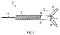
図1は、鉗子の例示的な実施形態の側面図を示す。 FIG. 1 shows a side view of an exemplary embodiment of forceps.
図2は、図1の鉗子の上面図を示す。 FIG. 2 shows a top view of the forceps of FIG. 1.
図3は、図1の鉗子の分解図を示す。 FIG. 3 shows an exploded view of the forceps of FIG.
図4Aは、図1の鉗子のためのストッパの例示的な実施形態を有するドライバの例示的な実施形態の側面図を示す。 4A shows a side view of an exemplary embodiment of a driver with an exemplary embodiment of a stopper for the forceps of FIG. 1. FIG.
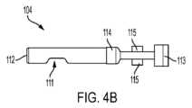
図4Bは、図4Aのドライバの上面図を示す。 FIG. 4B shows a top view of the driver of FIG. 4A.
図5Aは、図1の鉗子のためのベースコンポーネントの例示的な実施形態の外観図を示す。 5A shows an external view of an exemplary embodiment of a base component for the forceps of FIG. 1. FIG.
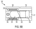
図5Bは、図1の鉗子のためのベースコンポーネントの例示的な実施形態の内面図を示す。 5B shows an interior view of an exemplary embodiment of a base component for the forceps of FIG. 1. FIG.
図5Cは、図1の鉗子のためのベースコンポーネントの別の例示的な実施形態の斜視図を示す。 5C shows a perspective view of another exemplary embodiment of a base component for the forceps of FIG. 1. FIG.
図5Dは、図5Cのベースコンポーネントの内側図を示す。 FIG. 5D shows an inside view of the base component of FIG. 5C.
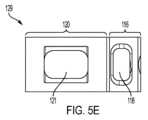
図5Eは、図5Cのベースコンポーネントの外観図を示す。 FIG. 5E shows an external view of the base component of FIG. 5C.
図6Aおよび6Bは、図1の鉗子のための顎部構成要素の例示的な実施形態を示す。 6A and 6B illustrate an exemplary embodiment of a jaw component for the forceps of FIG. 1. FIG.
図7Aは、図1の鉗子のための基部の例示的な実施形態およびドライバの例示的な実施形態を示し、ドライバは、基部に対して第1の位置にある。 FIG. 7A shows an exemplary embodiment of a base and an exemplary embodiment of a driver for the forceps of FIG. 1, with the driver in a first position relative to the base.
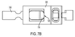
図7Bは、ドライバが基部に対して第2の位置にある、図7Aの基部およびドライバを示す。 FIG. 7B shows the base and driver of FIG. 7A with the driver in a second position relative to the base.
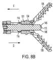
図8Aおよび図8Bは、それぞれ、第1及び第2の位置にある図7Aの基部及びドライバを有する図1の鉗子の側断面図を示し、図9A及び図9Bは、それぞれ第1及び第2の位置にある図7Aの基部及びドライバを有する図1の鉗子の上面図を示す。 8A and 8B show side cross-sectional views of the forceps of FIG. 1 with the base and driver of FIG. 7A in first and second positions, respectively, and FIGS. 9A and 9B show side cross-sectional views of the forceps of FIG. 7B shows a top view of the forceps of FIG. 1 with the base and driver of FIG. 7A in position; FIG.
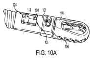
図10A及び図10Bは、それぞれ、閉鎖位置および開放位置にあるエンドエフェクタの例示的な実施形態を伴う、図1の鉗子の斜視図を示す。 10A and 10B illustrate perspective views of the forceps of FIG. 1 with exemplary embodiments of the end effector in closed and open positions, respectively.
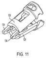
図11は、図11の基部接続部に接続するためのコネクタの例示的な実施形態の斜視図を示す。 FIG. 11 shows a perspective view of an exemplary embodiment of a connector for connecting to the base connection of FIG. 11.
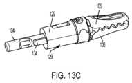
図12は、図11のベースコンポーネントのためのコネクタ要素の例示的な実施形態を示す。図13A~図13Cが図11の接続されたベースコンポーネントおよび図12のコネクタ要素を伴う、図1の鉗子の組み立ての段階を示す。 FIG. 12 shows an exemplary embodiment of a connector element for the base component of FIG. 11. 13A-13C illustrate stages of assembly of the forceps of FIG. 1 with the connected base component of FIG. 11 and the connector element of FIG. 12.
図14は、接続されたベースコンポーネントの別の例示的な実施形態の斜視図を示す。 FIG. 14 shows a perspective view of another exemplary embodiment of connected base components.
図15は、図14のベースコンポーネントのためのコネクタ要素の例示的な実施形態を示す。 FIG. 15 shows an exemplary embodiment of a connector element for the base component of FIG. 14.
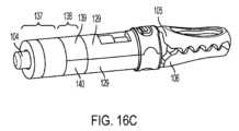
図16A~図16Cは図14の接続されたベースコンポーネントと図15のコネクタ要素とを有する図1のピンセットの組立段階を示す。 16A-16C illustrate stages of assembly of the tweezers of FIG. 1 with the connected base component of FIG. 14 and the connector element of FIG. 15.
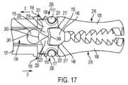
図17~図21は、図4Aのドライバと、図1のピンセットに対する図6A及び図6Bの顎部構成要素との係合を示す。 17-21 illustrate engagement of the driver of FIG. 4A with the jaw component of FIGS. 6A and 6B to the tweezers of FIG. 1.
以下の説明は、鉗子のための駆動アセンブリを含む様々な実施形態および詳細を提供することによって、実施形態の完全な理解を伝えることを意図している。
しかしながら、本発明は、これらの特定の実施形態および詳細に限定されるものではなく、これらは例示的なものに過ぎないことを理解されたい。
さらに、当業者は、既知のデバイス、システム、および方法に照らして、任意の数の代替実施形態における本発明の意図された目的および利益のための本発明の使用を理解することができる。 The following description is intended to convey a thorough understanding of the embodiments by providing various embodiments and details, including a drive assembly for the forceps.
However, it is to be understood that the invention is not limited to these particular embodiments and details, which are exemplary only.
Moreover, those skilled in the art can appreciate the use of the present invention for its intended purposes and benefits in any number of alternative embodiments in light of known devices, systems, and methods.
一般的には、種々のエンドエフェクタのための駆動アセンブリが利用され得るが、一例として、鉗子が選択された。
本明細書に記載される様々な例示的な実施形態の鉗子は、ドライバ上に少なくとも1つのストッパを有し、このストッパは、基部の少なくとも1つの開口部の側壁と係合し、その結果、ストッパが、基部開口部の最遠位壁と係合する場合、アセンブリの遠位端に取り付けられた顎部または任意の他の把持ツールは、完全に開放された位置にある。
同様に、ドライバ上の少なくとも1つのストッパが、基部開口部内の最近位壁に当接しているとき、アセンブリの遠位端に取り付けられた顎部または任意の他の把持ツールは、完全に閉鎖された位置にある。
駆動アセンブリが動き続けるのを防止する(したがって、顎部または他の把持ツールに力を供給する)ストッパを有することは、顎部が基部および/または駆動アセンブリと係合解除するのを防止し、顎部が所望の位置よりも開いた位置に過剰移動するのを防止する点で、有利である。 In general, drive assemblies for a variety of end effectors may be utilized, but forceps were selected as an example.
The forceps of various exemplary embodiments described herein have at least one stop on the driver that engages a sidewall of at least one opening in the base, such that When the stop engages the distal-most wall of the base opening, the jaws or any other grasping tool attached to the distal end of the assembly is in a fully open position.
Similarly, when at least one stop on the driver abuts the proximal-most wall within the base opening, the jaws or any other grasping tool attached to the distal end of the assembly is fully closed. It is located in the same position.
Having a stop that prevents the drive assembly from continuing to move (thus providing a force to the jaws or other gripping tool) prevents the jaws from disengaging from the base and/or the drive assembly; This is advantageous in that it prevents the jaws from moving too far into a position that is more open than desired.
例示的な実施形態では、組織サンプルを得るためのデバイスは、基部を備え、
基部は、中空内部と、開放遠位端と、開放近位端と、を有する円筒形シャフトと、シャフトの遠位部分に沿った第1の遠位開口部及び第2の遠位開口部と、第1及び第2の遠位開口部の近位にシャフトに沿った第1の近位開口部および第2の近位開口部と、を有する。
基部のシャフトの中心は、縦軸を規定する。
また、デバイスは、ドライバを有し、ドライバは、シャフトと、近位端と、遠位端と、前記ドライバシャフトから半径方向に延在する1つ以上のストッパ機構と、を含む。
基部の第1および第2の近位開口部は、遠位縁および近位縁を含み、ドライバが基部に対して遠位に移動されるときに、少なくとも1つのストッパ機構が近位開口部の遠位縁に当接し、ドライバが基部に対して近位に移動されるときに、少なくとも1つのストッパ機構が近位開口部の近位縁に当接する。 In an exemplary embodiment, a device for obtaining a tissue sample comprises a base;
The base includes a cylindrical shaft having a hollow interior, an open distal end, an open proximal end, and a first distal opening and a second distal opening along a distal portion of the shaft. , a first proximal opening and a second proximal opening along the shaft proximal to the first and second distal openings.
The center of the base shaft defines a longitudinal axis.
The device also includes a driver including a shaft, a proximal end, a distal end, and one or more stop mechanisms extending radially from the driver shaft.
The first and second proximal openings of the base include a distal edge and a proximal edge, and when the driver is moved distally relative to the base, the at least one stopper mechanism engages the proximal opening. At least one stop mechanism abuts the proximal edge of the proximal opening when the driver is moved proximally relative to the base.
組織サンプルを得るために顎アセンブリを有するデバイスの例示的な実施形態を使用する方法は、1つ以上の駆動ワイヤを遠位方向に押して、1つ以上の駆動部材を遠位方向に移動させることによって、1対の顎部を開く工程を包含する。
駆動アームの遠位移動は少なくとも2つの内部ジョーアームのそれぞれの外面を押すことによって、顎部の遠位端の互いに離れた開放を開始し、駆動部材は、また、内部ジョーアームの近位端と係合して、顎部が完全に開放された位置になるまで、内部ジョーアームの近位を押す。
組織サンプルを得るために本発明の例示的な実施形態を使用する方法は、また、1つまたは複数の駆動部材を近位方向に引っ張るステップを含むことができ、これは、顎部が閉鎖位置にあり、組織体積を把持するまで、内部ジョーアームの遠位表面に内部ジョーアームを近位方向に引張らせる。次いで、組織は、身体から引き裂かれ得るか、または除去され得る。 A method of using an exemplary embodiment of a device having a jaw assembly to obtain a tissue sample includes pushing one or more drive wires in a distal direction to move one or more drive members in a distal direction. and opening a pair of jaws.
The distal movement of the drive arm initiates the opening of the distal ends of the jaws apart from each other by pushing against the outer surfaces of each of the at least two internal jaw arms, and the drive member also pushes the proximal ends of the internal jaw arms. the proximal inner jaw arm until the jaws are in the fully open position.
A method of using an exemplary embodiment of the invention to obtain a tissue sample can also include pulling the one or more drive members proximally, such that the jaws are in a closed position. , and the distal surface of the internal jawarm is pulled proximally until the tissue volume is grasped. The tissue can then be torn or removed from the body.
特定の実施形態では、この方法は、少なくとも1つのストッパ機構が、基部の開口部の遠位縁部に当接するまで、少なくとも部分的に基部を通って遠位方向に沿って前方に駆動アームを押すステップであって、一対の顎部が開かれるステップと、顎部が閉じられるように、少なくとも1つのストッパ機構が基部の開口部の近位縁部に当接するまで、駆動アームを少なくとも部分的に基部を通って近位方向に沿って後方に引くステップと、を含む。 In certain embodiments, the method includes moving the drive arm forwardly along a distal direction at least partially through the base until the at least one stopper mechanism abuts a distal edge of the opening in the base. pushing the pair of jaws open and pushing the drive arm at least partially until the at least one stopper mechanism abuts a proximal edge of the opening in the base so that the jaws are closed; and pulling posteriorly along a proximal direction through the base.
様々な例示的な実施形態は、大量の組織をより大量の組織から引き離す、または引き離す一対の顎部を開閉するために使用することができる単一の駆動アームを有するデバイスを概して説明する。
しかしながら、様々な実施形態はそのように限定されない。例えば、様々な実施形態では、様々なスタイルの顎部をデバイス上で使用することができ、様々な延長部が例えば組織を穿孔または焼灼するために、ドライバの遠位端上に存在させることができる。 Various exemplary embodiments generally describe a device having a single drive arm that can be used to open and close a pair of jaws that separate or separate a large amount of tissue from a larger amount of tissue.
However, various embodiments are not so limited. For example, in various embodiments, different styles of jaws may be used on the device, and different extensions may be present on the distal end of the driver, for example, to puncture or cauterize tissue. can.
図1~図16Cは、組織サンプルを得るためのデバイス100の様々な例示的な実施形態を示す。
図1~図3を参照すると、デバイス100は2つの部品、すなわち、開放近位端と、開放遠位端と、中空内部と、を有し、実質的に円筒形の形状を形成するように互いに嵌合する、第1のベースコンポーネント102および第2のベースコンポーネント103からなるベース101を備える。
図1~図3は、また、ドライバ104および2つのエンドエフェクタ105および106の例示的な実施形態を示す。
図面を参照して本出願に記載されるエンドエフェクタ105、106は顎部であるが、エンドエフェクタは例えば、カッター、鉗子、マニピュレータ、または他の適切なエンドエフェクタなど、任意の適切な形態をとることができることを理解されたい。
ドライバアセンブリは、ばねシース107のようなシースに取り付けることができる。ドライバ104は、基部の中心を貫通する長手軸に沿って近位方向及び遠位方向に移動可能であり、ドライバの近位端に接続された駆動ワイヤ108によって位置決めすることができる。電流が流れることを意図していない場合、ドライバ104は、非導電性材料で作ることができる。駆動ワイヤ108は任意の適切な材料、例えば、任意の適切な金属または非金属材料から作製され得る。 1-16C illustrate various exemplary embodiments of a
Referring to FIGS. 1-3,
1-3 also show an exemplary embodiment of a
Although the
The driver assembly can be attached to a sheath, such as
図3を参照すると、例示的な一実施形態による駆動アセンブリの分解図が図示されている。
ドライバ104、ならびに第1のベースコンポーネント102および第2のベースコンポーネント103が示されている。また、図示されているのはコネクタ105、106であり、アーム109、110はドライバ及びベースコンポーネントと関係するように形状された近似端である。
ばねシースまたは他の市販のシースであってもよいシース107、および駆動ワイヤ108も図示されている。ドライバは、ステンレス鋼、または内視鏡鉗子器具用のドライバアームにおいて商業的に使用される任意の他の材料から作製され得る。ベースコンポーネントは、ステンレス鋼、または他の市販の材料で作ることもできる。残りの構成要素は、内視鏡把持器およびツール、ならびにそのようなツールに関連する駆動ワイヤの分野で使用されることが商業的に知られている任意の材料から作製することができる。 Referring to FIG. 3, an exploded view of a drive assembly according to an exemplary embodiment is illustrated.
A
Also shown is a
図4Aは、例示的な実施形態によるドライバ104の側面図を示し、図4Bは上面図を示す。
ドライバ104は、近位端および遠位端を有する実質的に細長い部材である。ドライバ104の近位端は側部111に開口部を有し、近位端112に開口部を有し、駆動ワイヤ108が取り付けられることを可能にし、したがって、シースおよび基部を通って近位方向および遠位方向の両方にドライバ104を移動させることができる。 4A shows a side view and FIG. 4B shows a top view of
ドライバ104の遠位端は、顎部105、106と係合するための係合機構113を含む。
係合機構113は、顎部105、106に当接して係合するように設計された様々な形状のうちの1つとすることができる。図4Aに示すようなドライバ104の遠位部分は、ドライバ104の近位部分よりも狭い断面積を有することができる。
図4Aおよび図4Bを参照すると、特定の実施形態では、ドライバ104は、また、遠位係合機構113と比較してドライバ104のより近位の位置に配置された2つのストッパ115を含む。ストッパ115は、また、顎部105、106と係合するためのものである。ドライバ104はまた、2つのストッパ114を備えており、顎部105、106が開放されるときにドライバ104が遠方に移動しすぎないように、また、顎部105、106が閉じられるときには近方に移動しすぎるように、ベース101と接続する位置にある。 The distal end of
Referring to FIGS. 4A and 4B, in certain embodiments, the
図5Aおよび5Bは、例示的な実施形態による鉗子のための駆動アセンブリのベース101を構成するベースコンポーネント102、103の例示的な実施形態を示す。
図5Aは、ベースコンポーネント102の外面を示す。図5Bは、ベースコンポーネント102の内面図を示す。表面の曲率は、図10Aおよび10Bの斜視図で明らかである。ベースコンポーネント102、103の遠位部分116は顎部105、106の近位端が嵌合し、その周りを旋回するための開口118を有する。ベースコンポーネント102、103の近位部分120は、ドライバ104のストッパ114を受け入れるための近位開口121を有する。すなわち、近位開口121は、ストッパ114がアセンブリの長手方向軸に垂直な方向に、少なくとも部分的に貫通して嵌合するように寸法決めされる。
図5Bは、第2のベースコンポーネント103上の整列したピン及びくぼみと連動する、1つのベースコンポーネント102のピン122及びくぼみ123を更に示す。ベース101の遠位部分116はまた、エンドエフェクタが開閉するときに、エンドエフェクタのための旋回点を提供するために使用され得る外側リング117を有する。ベースコンポーネント103は例示的な実施形態によれば、ベースコンポーネント102と同一とすることができる。 5A and 5B illustrate an exemplary embodiment of
FIG. 5A shows the outer surface of
FIG. 5B further shows the
図5C~図5Eは、ベースコンポーネント129の別の例示的な実施形態を示す。
図5Aおよび図5Bに示す実施形態と同様に、2つの同一のベースコンポーネント129は基部を構成するように一緒に連結することができ、ベースコンポーネント102、103の代わりに使用することができる。ベースコンポーネント129は、ベースコンポーネント102と実質的に同じ形状および開口を有する。2つのベースコンポーネント129は、連結部品によって互いに嵌合することができる。各ベースコンポーネント129は、ベースコンポーネントの遠位部分116の他方の側の突出部(図示せず)とぴったりと嵌合するように形成された、遠位部分116の一方の側の窪み(図示せず)を有することができる。
図示の実施形態では、ベースコンポーネントの近位部分120上の窪み132が他方のベースコンポーネントの近位部分120上に位置する突起133との接続嵌合を形成する。エンドエフェクタ内部のアーム109、110は遠位開口118とインターロックし、ストッパ114は本明細書でベースコンポーネント102、103に関して説明したように、ベースコンポーネントの近位開口121とインターロックする。 5C-5E illustrate another exemplary embodiment of
Similar to the embodiment shown in FIGS. 5A and 5B, two
In the illustrated embodiment, a
図11を参照すると、ベースコンポーネント129のためのコネクタ134の実施形態が示されている。
コネクタ134は、フッ素化エチレンプロピレンまたは電流を伝導しない他のポリマーから作製され得るか、またはベースコンポーネントと同じ材料から作製され得る。ベースコンポーネントは図5C~図5Eに示されるベースコンポーネント129の形態をとることができ、または図5A~図5Bに示されるベースコンポーネント102、103の形態をとることができる。
図12は、ベースコンポーネント129から独立した単一のコネクタ要素134を示す。
コネクタは、形成され、可撓性であり、実質的に「v」形状を有することができ、「v」の屈曲部は近位端を画定し、2つの脚部は、遠位端に向かって延在する。コネクタは遠位端で開いており、近位端で閉じている。コネクタの遠位端はコネクタがベースコンポーネントに接続される場所であり、1つの脚135が各ベースコンポーネント129の近位端に接続される。コネクタは、装置の組立、特にドライバ104及びエンドエフェクタ105、106上へのベースコンポーネントの組立を補助する。コネクタ134は、ポリマーを鋳型に注ぐことによって作製され得るか、または任意の他の公知の方法によって作製され得る。 Referring to FIG. 11, an embodiment of a
FIG. 12 shows a
The connector can be formed and flexible and have a substantially "v" shape, with the bend of the "v" defining a proximal end and two legs extending toward a distal end. and extend. The connector is open at the distal end and closed at the proximal end. The distal end of the connector is where the connector is connected to the base component, and one
図13Aに示すように、顎部105、106は、ドライバ104の遠位端上に組み立てられている。ベースコンポーネント129は、コネクタ134で互いに接続されており、開いた構成にある間、ベースコンポーネント129は、駆動アーム104の上に配置される準備ができている。
図13Bは、ベースコンポーネントが駆動アーム104を取り囲み、依然として開放構成であるような位置に移動されたときのベースコンポーネントを示す。ベースコンポーネント129上の突起および窪みは、図5C~図5Eを参照して説明したものとすることができる。図13Bを参照すると、一方のベースコンポーネント129の突起は、他方のベースコンポーネント129の窪みとまだ接触していない。
いくつかの実施形態では、ベースコンポーネント129は、一緒に溶接することができる。コネクタ134は図13Cに図示されているように、ベースコンポーネント129が駆動アーム104及び顎部105、106の上で閉じた位置に移動されるときに、突起及び凹みが適切な位置合わせを達成するのを補助する。ベースコンポーネント129が閉鎖位置に移動されると、エンドエフェクタ105、106のアーム109、110およびドライバ105のストッパ113、115はベースコンポーネント129の遠位開口118に近接し、ドライバ104のストッパ114、115は、ベースコンポーネント129の近位開口121内にある。一旦組み立てられると、コネクタ134は、ベースコンポーネント129から取り外すことができる。ベースコンポーネント129からコネクタ134を取り外す必要はない。 As shown in FIG. 13A,
FIG. 13B shows the base component when it has been moved to a position such that it surrounds the
In some embodiments,
図14は、ベースコンポーネント129を一緒にクランプすることを補助するために使用することができる、スプリットフォーク曲げ可能ジョイント136の例示的な実施形態を示す。
図15に示されるように、スプリットフォーク曲げ可能ジョイント136は、近位部分137および遠位端138を有する。近位部分137は、駆動アームの近位端上に嵌合するのに十分なサイズの管腔が貫通する円筒形状を有することができる。遠位端138は、スプリットフォーク曲げ可能継手のスプリットフォーク端とすることができ、閉鎖位置にあるときに円筒形状を有することができ、2つの別個の部品139および140が長手方向軸に沿って互いに離れるように角度が付けられるが、近位部分137に接合されたままであるように、スプリットに沿って分離することができる。
再び図14を参照すると、スプリットフォーク曲げ可能ジョイント136の遠位端部片139、140は、ベースコンポーネント129の近位端部に取り付けることができる。分割フォーク端部139、140は、任意の合理的な方法でベースコンポーネント129に固定することができる。例示的な実施形態では、それらはベースコンポーネントに成形されるか、または接着されるか、または溶接され得る。近位部分137は、バレルとすることができる。バレルは、様々な長さを有することができる。スプリットフォーク曲げ可能継手は、フッ素化エチレンプロピレン、または電流を伝導せず、それに対して柔軟性を有する任意の材料で作ることができる。 FIG. 14 shows an exemplary embodiment of a split fork bendable joint 136 that can be used to assist in clamping
As shown in FIG. 15, split fork bendable joint 136 has a
Referring again to FIG. 14, the
図16Aに示すように、エンドエフェクタ105、106は、ドライバ104の遠位端上に組み立てられている。
スプリットフォーク曲げ可能ジョイント136の遠位端部片139、140はベースコンポーネント129の近位端に固定されているが、開放構成のままである。
図16Bは、ベースコンポーネントが駆動アーム104を取り囲み、依然として開放構成であるような位置に移動されたときのベースコンポーネントを示す。
例示的な実施形態では、ベースコンポーネント129上の突起および窪みは図5C~図5Eのものとすることができる。
図16Bを参照すると、一方のベースコンポーネント129の突起は、他方のベースコンポーネント129の窪みとまだ接触していない。特定の実施形態では、ベースコンポーネント129を一緒に溶接することができる。スプリットフォーク曲げ可能ジョイント136は図16Cに例示されているように、ベースコンポーネント129が駆動アーム104及び顎部105、106の上で閉じた位置に移動されるときに、突起及びくぼみが適切な整合を達成するのを補助する。ベースコンポーネント129が閉鎖位置に移動されると、エンドエフェクタ105、106のアーム109、110およびドライバ104のストッパ113、115はベースコンポーネント129の遠位開口118に近接し、ドライバ104のストッパ114、115は、ベースコンポーネント129の近位開口121内にある。 As shown in FIG. 16A,
The
FIG. 16B shows the base component when it has been moved to a position such that it surrounds the
In an exemplary embodiment, the protrusions and indentations on
Referring to FIG. 16B, the protrusion of one
本明細書に記載されるコネクタおよびスプリットフォーク曲げ可能ジョイントの使用は、鉗子に限定されず、内視鏡ツールおよび生検把持器のより効率的な組立プロセスのために使用されてもよい。 The use of connectors and split fork bendable joints described herein is not limited to forceps, but may be used for a more efficient assembly process of endoscopic tools and biopsy graspers.
例示的な実施形態では、スリップリング(図示せず)を使用して、組み立ておよび/または溶接プロセス中に、ベースコンポーネント129を一緒に保持することができる。スリップリングは、コネクタまたは分割フォーク曲げ可能なジョイントから独立して、またはそれと併用することができる。 In an exemplary embodiment, a slip ring (not shown) may be used to hold
図8A~図8Bおよび図17~図21を参照すると、エンドエフェクタ105、106はドライバ104を方向Dに移動させることによって、閉位置(図8Aに示されるよう)から開位置(図8Bに示されるよう)に移動され、エンドエフェクタ105、106は、ドライバ104を方向Xに移動させることによって、開位置から閉位置に移動される。
エンドエフェクタ105、106が閉位置にあるとき、ドライバ104の遠位端の係合機構113は、エンドエフェクタ105、106の角度付き表面217と係合するように配置され、1つまたは複数のストッパ115(図4Aおよび図4B)はエンドエフェクタ105、106のアーム109、110(図17~図21)と係合するように配置される。
図示の実施形態では、係合機構113がエンドエフェクタ105、106の傾斜面217と係合するための傾斜面145、146を有する。
ドライバ104がD方向に移動すると、遠位係合機構113がエンドエフェクタ105、106の傾斜面217に係合し、1つまたは複数のストッパ115がエンドエフェクタ105、106のアーム109、110に係合する。ドライバ104の方向Xへの移動は、係合特徴113をアーム109、110に係合させ、エンドエフェクタ105、106の閉位置への移動を容易にする。 8A-8B and FIGS. 17-21, the
When the
In the illustrated embodiment,
As the
図17を参照すると、図示の実施形態ではエンドエフェクタ105、106は、第1の顎部105および第2の顎部106を含む一対の顎部である。
各顎部105、106は近位部分230および遠位部分216を有し、近位部分230はベース101に接続され、遠位部分116はベース101から遠位方向に延びる。第1の顎部105および第2の顎部106の両方の近位部分230は、ベース101に接続するための少なくとも1つのアーム109、110を含む。アーム109、110は、内側に延びる部品220、外側に延びる突出部231、近位に位置する湾曲部分218、および外側に湾曲部分221を含むことができる。顎部105、106がベース101に接続されると、ベース101の外側リング117がアーム109、110の外側の湾曲部分221に配置され、顎部105、106が基部の外側リング117の周りを旋回することができる。内側に延在する部品220はドライバ104のストッパ113、115がアーム109、110と係合することができるように、ベース101の中空内部に延在する。
特定の実施形態では、外側に延在する突出部231が、顎部105、106が開位置と閉位置との間で旋回するときに、外側に延在する突出部231がベース101の外壁を越えて外側に延在しないように、ベース101の遠位開口118内に延在する。 Referring to FIG. 17, in the illustrated embodiment, the
Each
In certain embodiments, the outwardly extending
さらに図17を参照すると、ドライバ104は、第1のストッパ113と第2のストッパ115とを含む。
特定の実施形態では第1の係合機構113が傾斜面145、146を有する遠位部分と、凹状近位表面249を有する近位部分とを有し、ストッパ115は丸い近位表面241および凹状遠位表面243を有する。ストッパ115の凹状遠位表面243はアーム109、110がロックまたは詰まることなくベース101の周りを旋回するように、アーム109、110に係合して、エンドエフェクタ105、106のアーム109、110を引き起こすように構成される。
例えば、ストッパ115の凹状遠位表面243は、アーム109、110の近位に位置する湾曲部分218と係合して、アーム109、110をベース101の周りに旋回させ、アーム109、110がロックまたは詰まるのを防止するように構成される。同様に、係合機構113の凹状近位表面249はエンドエフェクタ105、106が閉鎖位置に移動されているときにアーム109、110と係合するように構成され、アーム109、110はロックされたり詰まったりすることなく、ベース101の周りを旋回する。
特定の実施形態では、ストッパ115の丸い近位表面241がアーム109、110の近位に位置する湾曲部分218と係合して、エンドエフェクタ105、106が完全に開いた位置になると、アーム109、110が旋回するのを防止するように構成される。 Further referring to FIG. 17,
In certain embodiments, the
For example, concave
In certain embodiments, the rounded
図17~図21は、エンドエフェクタ105、106を開位置と閉位置との間で移動させるための、ドライバ104とエンドエフェクタ105、106との間の係合の例示的な実施形態を示す。
図17を参照すると、初期位置において、ドライバ104上の第1の係合特徴113は各顎部105、106の角度をつけた表面217と係合するように位置決めされ、ドライバ104の第2のストッパ115はアーム109、110と係合するように位置決めされる。
図18を参照すると、ドライバ104は方向Dに移動され、これによって、ストッパ113が顎部105、106の角度をつけた表面217に係合し、顎部105、106を第1の部分的に開いた位置に移動させる。
図19を参照すると、ドライバ104の方向Dへの継続した移動によって、ストッパ115はアーム109、110と係合し、アーム109、110をベース101のリング117の周りで枢動させて、顎部105、106が第2の部分的に開放された位置に移動するようにする。第2の部分的に開いた位置では、係合機構113がもはや顎部105、106と係合しておらず、各顎部105、106の遠位部分216の間の領域内に延びている。 17-21 illustrate exemplary embodiments of engagement between the
17, in the initial position, the
Referring to FIG. 18, the
Referring to FIG. 19, continued movement of the
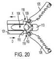
図20を参照すると、ドライバ104は、顎部105、106が全開位置になるまで、方向Dに移動される。
特定の実施形態では、顎部105、106が完全に開いた位置にあるとき、ストッパ115は顎部106、107を定位置にロックし、顎部がそれ以上開くことができないようにする。顎部106、107を閉じると(図8Aに示すように)、顎部間の内角は約ゼロ(0)度であり、顎部を全開すると(図20に示すように)、顎部間の内角は最大であり、約85度から約110度の範囲であり得る。 Referring to FIG. 20,
In certain embodiments, when the
図21は、顎部105、106が開放位置から閉鎖位置に移動し始める様子を示している。
図示の実施形態では、ドライバ104は近位方向Xに引っ張られ、これによりドライバ104の係合機構113が内向きアーム109、110に係合し、アーム109、110が近位方向に押され、それによって顎部の湾曲部分221がベース101のリング117の周りで旋回する。したがって、顎部は旋回して閉じ、顎部間の角度は減少する。 FIG. 21 shows the
In the illustrated embodiment,
図7Aおよび図7Bを参照すると、ストッパ114、115は、ベース101の開口121内に嵌合するような大きさおよび形状である。
ストッパ114は、エンドエフェクタ105、106がベース101および/またはドライバ104から外れるのを防止するように構成され、ストッパ114はエンドエフェクタが開位置に移動しているときにエンドエフェクタ105、106の過剰移動を防止するように構成される。
図7Aおよび図8Aを参照すると、ストッパ114がベース101に対して第1の位置にあるとき、ストッパ114は、エンドエフェクタ106、107が係合解除するのを防止する。第1の部分では、ストッパ114がベース101の近位開口121の近位側124に係合する。
図7Bおよび図8Bを参照すると、ストッパ114がベース101に対して第2の位置にあるとき、ストッパは、エンドエフェクタが完全に開いた位置を越えて開くのを防止する。第2の位置では、ストッパ114が近位開口121の遠位側125に係合する。すなわち、ストッパ114と近位開口121の遠位側125との間の係合はエンドエフェクタが開くことができる最大角度を設定し、エンドエフェクタがベース101および/またはドライバ104から離脱することによって、エンドエフェクタを開放し、意図せずに開放位置にロックするには過度の力の印加を防止する。 Referring to FIGS. 7A and 7B, stops 114, 115 are sized and shaped to fit within opening 121 of
The
7A and 8A, when
7B and 8B, when
さらに、単一のドライバ104および少なくとも1つのストッパ114は、構成要素の断面積または直径の増加がないので、アセンブリが内視鏡的に使用されることを可能にする。アクチュエータアセンブリおよび駆動ワイヤと組み合わせて使用してドライバを制御する場合でも、デバイスから半径方向外側に延びる駆動アームは存在しない。2つのストッパ114があってもよい。 Additionally, the
図6Aおよび図6Bを参照すると、例示的な実施形態による顎部構成要素105、106が示されている。
ここに示された顎部構成要素105、106は、限定することを意味するものではない。任意のカップ、把持要素、サンプリング要素、生検要素、切断要素、熱適用要素、または薬物送達要素など、任意のエンドエフェクタ要素を、図6Aおよび6Bに示される顎の代わりに使用することができる。
図6Aは、顎部構成要素105の外観図を示す。図6Bは、顎部構成要素106の内側図を示す。
顎部構成要素105、106は各々、近位端を有し、各々、内向きに延びるアーム109(または顎部構成要素106上の110)を有する。
例示的な実施形態における内側に延びるアームはベース101の遠位開口118と係合し、顎のエンドエフェクタ部分が基部の遠位端の開口126から遠位に延びるようなサイズおよび形状である。
特定の実施形態では、アーム109、110はエンドエフェクタが開位置と閉位置との間で移動するときに、ベース101の外壁を越えて延びない。
これらの実施形態は、デバイス100の使用中に周囲組織と接触することができる(基部の外壁を越えたときに外向きに延びる突起を含む従来の鉗子と比較して)、ベース101の長手方向軸から外向きに延びる突起が少ないので有利である。エンドエフェクタは開口部128を有することができるが、必ずしも必要ではない。 6A and 6B,
The
FIG. 6A shows an external view of
The inwardly extending arms in the exemplary embodiment are sized and shaped to engage the
In certain embodiments, the
These embodiments provide a longitudinal extension of the base 101 (compared to conventional forceps that includes protrusions that extend outwardly when beyond the outer wall of the base) that can contact surrounding tissue during use of the
例示的な実施形態において、2つの顎部構成要素105、106はそれぞれ移動可能であり、駆動アームの位置に基づいて開閉可能である。
別の例示的な実施形態では、1つの顎部が可動であり、別の顎部が静止していてもよい。この例示的な実施形態では、固定ジョー成分がベース成分に固定して取り付けることができる。駆動アームおよび基部成分は、固定顎部成分を収容するように調整することができる。可動ジョー成分は本明細書に記載されるように、開閉するように動作することができる。 In the exemplary embodiment, the two
In another exemplary embodiment, one jaw may be movable and another may be stationary. In this exemplary embodiment, a fixed jaw component can be fixedly attached to the base component. The drive arm and base component can be adjusted to accommodate the fixed jaw component. The movable jaw component is operable to open and close as described herein.
図9Aおよび9Bは、それぞれ、閉鎖位置および開放位置にあるデバイス100の上面図である。
図9Aおよび図9Bは開位置および閉位置の両方において、構成要素のすべてがどのように互いに嵌合し、互いに係合するかの追加の例示を提供する。
図9Aの閉鎖位置では、ストッパ114がベース101の近位開口121の近位壁に接している。ベース101の遠位開口118はエンドエフェクタがベース101の外側リング117の周りで旋回することができるように、それを通って少なくとも部分的に延びる顎アーム109の一部を有する。
図9Bでは、ストッパ114およびドライバ104は、両方とも遠位方向に前方に押し出されており、エンドエフェクタ105、106は開いている。ストッパ114は、遠位開口125の遠位部分と接触している。エンドエフェクタ105、106は基部の外側リング117上で旋回し、顎アーム109のより小さい部分は、基部の遠位開口118を通って延びる。図9Bでは、ドライバ104の遠位端が遠位方向にベース101を越えて延出している。 9A and 9B are top views of
9A and 9B provide additional illustrations of how all of the components fit together and engage each other in both the open and closed positions.
In the closed position of FIG. 9A,
In FIG. 9B,
図10Aおよび10Bは、例示的な実施形態によるアセンブリの斜視図を示す。
図10Aは、ドライバ104がベース101に対して近位位置にあり、エンドエフェクタ105、106が閉じているときのアセンブリの上面図である。
図10Bは、ドライバ104がベース101に対して遠位位置にあり、エンドエフェクタ105、106が最大開放位置にあるときの図であり、エンドエフェクタ105、106はベース101の開口121の遠位壁に対するストッパ114の拘束のために、エンドエフェクタ105、106が最大開放位置にあることができる。 10A and 10B show perspective views of an assembly according to an exemplary embodiment.
FIG. 10A is a top view of the assembly with
FIG. 10B shows the
別の例示的な実施形態では、3つまたは4つの顎部があってもよい。ベースコンポーネントおよび駆動アームは、複数の顎を収容するようなサイズおよび形状であり得る。3つまたは4つの顎部の実施形態では、1つの固定ジョーがあってもよく、またはすべての顎部が駆動アームの移動に従って開閉することができる。
本明細書に記載の実施形態は例示的なものであり、任意のエンドエフェクタを、任意の組み合わせで、固定または可動ジョーのいずれかに使用することができる。 In another exemplary embodiment, there may be three or four jaws. The base component and drive arm may be sized and shaped to accommodate multiple jaws. In three or four jaw embodiments, there may be one fixed jaw, or all jaws may open and close according to movement of the drive arm.
The embodiments described herein are exemplary and any end effector, in any combination, may be used with either fixed or movable jaws.
したがって、様々な実施形態は、本明細書で説明される特定の実施形態によって範囲が限定されるべきではない。
さらに、実施形態のいくつかは特定の目的のために特定の環境における特定の実装の文脈で本明細書に記載されてきたが、当業者はその有用性がそれに限定されず、様々な実施形態が任意の数の目的のために任意の数の環境において有益に実装され得ることを認識すべきである。
したがって、以下に記載される特許請求の範囲は、本明細書に開示される実施形態の全範囲および精神を考慮して解釈されるべきである。
前述の説明は多くの詳細および特異性を含むが、これらは説明の目的のためだけに含まれており、様々な実施形態の限定として解釈されるべきではないことを理解されたい。
上述の実施形態に対する多くの修正は、この説明の精神および範囲から逸脱することなく行うことができる。 Therefore, the various embodiments should not be limited in scope by the specific embodiments described herein.
Additionally, while some of the embodiments have been described herein in the context of a particular implementation in a particular environment for a particular purpose, those skilled in the art will appreciate that their usefulness is not limited thereto and that various embodiments It should be recognized that may be beneficially implemented in any number of environments for any number of purposes.
Therefore, the claims set forth below should be construed in light of the full scope and spirit of the embodiments disclosed herein.
Although the foregoing description contains many details and specificities, it is to be understood that these are included for illustrative purposes only and are not to be construed as limitations on the various embodiments.
Many modifications to the embodiments described above can be made without departing from the spirit and scope of this description.
Claims (9)
Translated fromJapanese前記基部は、中空内部を含む円筒形シャフトを形成するように互いに嵌合可能な、第1のベースコンポーネントと、第2のベースコンポーネントと、を有し、
前記基部の前記遠位部分は、1つ以上の遠位開口と、1つ以上の前記エンドエフェクタのための旋回点を提供するために使用される外側リングと、を有し、
前記エンドエフェクタは、その近位端に設けられ、前記基部の前記遠位開口内に少なくとも部分的に配置される1つ以上のアームを有し、開位置と閉位置との間で移動可能となされ、
前記駆動アセンブリは、ドライバを有し、
前記円筒形シャフトは、近位部分および遠位部分を含み、前記近位部分には、1つ以上の近位開口が設けられ、
前記ドライバは、ドライバシャフトと、近位端と、遠位端と、前記ドライバシャフトから半径方向に延在する1つ以上のストッパ機構と、を含み、
前記ドライバは、さらに、前記1つ以上のストッパ機構が前記基部の前記1つ以上の近位開口内で移動可能であるように、前記基部の前記中空内部内に少なくとも部分的に配置され、
前記ストッパ機構の少なくとも1つは、前記1つ以上の近位開口の遠位縁に係合して、前記基部に対するドライバの遠位方向への移動を防止し、前記1つ以上の近位開口の近位縁に係合して、前記基部に対する前記ドライバの近位方向への移動を防止し、
前記遠位方向への前記ドライバの移動は、1つ以上の前記エンドエフェクタを前記開位置に移動させ、前記近位方向への前記ドライバの移動は、1つ以上の前記エンドエフェクタを前記閉位置に移動させ、
前記アームには、前記外側リングが配置されることで、前記エンドエフェクタを、その開位置及び閉位置への移動に伴って、前記外側リング周りに旋回させるための湾曲部分が形成されている、内視鏡デバイス。 a base, one or more end effectors connected to a distal portion of the base, and a drive assembly for moving the end effectors between open and closed positions;
the base has a first base component and a second base component that arematable with each other to form a cylindrical shaft including a hollow interior;
the distal portion of the base has one or more distal openings and an outer ring used to provide a pivot point for the one or more end effectors;
The end effector has one or more armsdisposed at a proximal end thereof and disposed at least partially within the distal opening of the base and is movable between an open position and a closed position. done,
the drive assembly includes a driver;
the cylindrical shaft includes a proximal portion and a distal portion, the proximal portion being provided with one or more proximal openings;
The driver includes a driver shaft, a proximal end, a distal end, and one or more stop mechanisms extending radially from the driver shaft;
The driver is further disposed at least partially within the hollow interior of the base such that the one or more stop mechanisms are movable within the one or more proximal openings of the base;
At least one of the stop mechanisms engages a distal edge of the one or more proximal apertures to prevent distal movement of the driver relative to the base; engaging a proximal edge of the driver to prevent proximal movement of the driver relative to the base;
Movement of the driver in the distal direction moves one or more of the end effectors to the open position, and movement of the driver in the proximal direction moves one or more of the end effectors to the closed position. move it to
The arm is provided with a curved portion for pivoting the end effector around the outer ring as the end effector moves to an open position and a closed position. Endoscopic device.
前記第1のストッパ機構は、前記第1の近位開口内で移動可能であり、
前記第2のストッパ機構は、前記第2の近位開口内で移動可能である、請求項2に記載の内視鏡デバイス。 the one or more stopper mechanisms of the driver include a first stopper mechanism and a second stopper mechanism;
the first stopper mechanism is movable within the first proximal opening;
3. The endoscopic device of claim 2, wherein the second stop mechanism is movable within the second proximal opening.
前記係合機構は、1つ以上の前記エンドエフェクタの1つ以上の前記アームと係合して、1つ以上の前記エンドエフェクタを開位置と閉位置との間で移動させるように構成されている、請求項1に記載の内視鏡デバイス。 the driver of the drive assembly includes one or more engagement mechanisms disposed along the driver shaft;
The engagement mechanism is configured to engage one or more of the arms of one or more of the end effectors to move the one or more end effectors between an open position and a closed position. The endoscopic device according to claim 1.
前記遠位凹面は、前記ドライバが遠位方向に移動するときに、1つまたは複数の前記エンドエフェクタがロックすることを防止するように構成される、請求項5に記載の内視鏡デバイス。 the second engagement feature has a rounded proximal surface and a distal concave surface;
6. The endoscopic device of claim 5, wherein the distal concave surface is configured to prevent the one or more end effectors from locking when the driver moves in a distal direction.
Applications Claiming Priority (5)
| Application Number | Priority Date | Filing Date | Title |
|---|---|---|---|
| US201762586515P | 2017-11-15 | 2017-11-15 | |
| US201762586573P | 2017-11-15 | 2017-11-15 | |
| US62/586,573 | 2017-11-15 | ||
| US62/586,515 | 2017-11-15 | ||
| PCT/US2018/061392WO2019099752A1 (en) | 2017-11-15 | 2018-11-15 | End effectors actuation platform |
Publications (3)
| Publication Number | Publication Date |
|---|---|
| JP2021502858A JP2021502858A (en) | 2021-02-04 |
| JP2021502858A5 JP2021502858A5 (en) | 2021-12-16 |
| JP7448112B2true JP7448112B2 (en) | 2024-03-12 |
Family
ID=64572609
Family Applications (1)
| Application Number | Title | Priority Date | Filing Date |
|---|---|---|---|
| JP2020526537AActiveJP7448112B2 (en) | 2017-11-15 | 2018-11-15 | End effector actuation platform |
Country Status (4)
| Country | Link |
|---|---|
| US (2) | US11033288B2 (en) |
| EP (1) | EP3709896A1 (en) |
| JP (1) | JP7448112B2 (en) |
| WO (1) | WO2019099752A1 (en) |
Families Citing this family (6)
| Publication number | Priority date | Publication date | Assignee | Title |
|---|---|---|---|---|
| JP7448112B2 (en)* | 2017-11-15 | 2024-03-12 | ユナイテッド ステイツ エンドスコピー グループ,インコーポレイテッド | End effector actuation platform |
| CN110876631A (en)* | 2019-08-27 | 2020-03-13 | 南微医学科技股份有限公司 | Disposable biopsy forceps |
| US11890027B2 (en)* | 2019-12-20 | 2024-02-06 | United States Endoscopy Group, Inc. | Microforceps |
| US11839395B2 (en)* | 2020-05-19 | 2023-12-12 | Covidien Lp | Three-prong laparoscopic grasping device |
| CN111449696A (en)* | 2020-05-26 | 2020-07-28 | 南微医学科技股份有限公司 | Binding clip and biopsy forceps |
| CN119791738B (en)* | 2025-01-17 | 2025-07-29 | 江苏唯德康医疗科技有限公司 | Handle device of minimally invasive medical instrument for endoscope |
Citations (3)
| Publication number | Priority date | Publication date | Assignee | Title |
|---|---|---|---|---|
| JP2000023986A (en) | 1998-03-26 | 2000-01-25 | Nivarox Far Sa | Instrument for collecting specimen for biopsy for instance, and rack system mounted on such instrument |
| JP2005512606A (en) | 2001-04-06 | 2005-05-12 | シャーウッド・サービシーズ・アクチェンゲゼルシャフト | Blood vessel sealing machine and dividing machine |
| JP2010284551A (en) | 2003-11-12 | 2010-12-24 | Applied Medical Resources Corp | Overmolded grasper jaw |
Family Cites Families (26)
| Publication number | Priority date | Publication date | Assignee | Title |
|---|---|---|---|---|
| US3895636A (en) | 1973-09-24 | 1975-07-22 | William Schmidt | Flexible forceps |
| US5172700A (en)* | 1989-01-31 | 1992-12-22 | C. R. Bard, Inc. | Disposable biopsy forceps |
| EP0513471A3 (en) | 1991-04-19 | 1993-02-03 | Lutz Kothe | Surgical instrument |
| US5636639A (en) | 1992-02-18 | 1997-06-10 | Symbiosis Corporation | Endoscopic multiple sample bioptome with enhanced biting action |
| US5478351A (en)* | 1992-06-24 | 1995-12-26 | Microsurge, Inc. | Endoscopic surgical tool with handle and detachable tool assembly |
| US5275615A (en)* | 1992-09-11 | 1994-01-04 | Anthony Rose | Medical instrument having gripping jaws |
| US5471992A (en)* | 1994-02-08 | 1995-12-05 | Boston Scientific Corporation | Multi-motion cutter multiple biopsy sampling device |
| US5871453A (en) | 1994-02-08 | 1999-02-16 | Boston Scientific Corporation | Moveable sample tube multiple biopsy sampling device |
| DE29516265U1 (en)* | 1995-10-13 | 1995-12-07 | Mathias Bäuerle GmbH, 78112 St Georgen | Upsizing machine with a saddle folder |
| US5762069A (en)* | 1995-12-29 | 1998-06-09 | Akos Biomedical, Inc. | Multiple sample biopsy forceps |
| US5843000A (en)* | 1996-05-07 | 1998-12-01 | The General Hospital Corporation | Optical biopsy forceps and method of diagnosing tissue |
| DE29711524U1 (en) | 1997-07-02 | 1997-08-28 | Aesculap AG & Co. KG, 78532 Tuttlingen | Surgical tubular shaft instrument |
| EP0945105A1 (en)* | 1998-03-26 | 1999-09-29 | Nivarox-FAR S.A. | Rack guide for a sampling device, e.g. a biopsy forceps |
| US6159162A (en) | 1998-05-04 | 2000-12-12 | Lsvp International, Inc. | Biopsy apparatus |
| US6086606A (en)* | 1998-05-06 | 2000-07-11 | Knodel; Bryan D. | Manually-operable surgical tool suitable for laparoscopic operations, readily adaptable for different functions by quick change of tissue-contacting operational elements |
| US6149607A (en)* | 1998-08-04 | 2000-11-21 | Endonetics, Inc. | Multiple sample biopsy device |
| US7101371B2 (en) | 2001-04-06 | 2006-09-05 | Dycus Sean T | Vessel sealer and divider |
| US7951165B2 (en)* | 2003-08-18 | 2011-05-31 | Boston Scientific Scimed, Inc. | Endoscopic medical instrument and related methods of use |
| EP2265184A1 (en)* | 2008-03-06 | 2010-12-29 | Trustees of Boston University | Low cost disposable medical forceps to enable a hollow central channel for various functionalities |
| ES2806255T3 (en) | 2009-10-08 | 2021-02-17 | Sumitomo Bakelite Co | Endoscope scissors |
| US8545519B2 (en) | 2009-12-22 | 2013-10-01 | Cook Medical Technologies Llc | Medical devices with detachable pivotable jaws |
| EP2627264B1 (en)* | 2010-10-11 | 2015-06-17 | Cook Medical Technologies LLC | Medical devices with detachable pivotable jaws |
| JP5681814B2 (en)* | 2010-12-15 | 2015-03-11 | クック メディカル テクノロジーズ エルエルシーCook Medical Technologies Llc | Medical device with removable pivotable jaws |
| DE102012201081A1 (en) | 2012-01-25 | 2013-07-25 | Herbert Maslanka | Surgical instrument |
| US9844389B2 (en) | 2014-10-10 | 2017-12-19 | Scholten Surgical Instruments, Inc. | Push-to-close actuated dual action spaced pivot assembly for surgical instrument jaws, blades, and forceps |
| JP7448112B2 (en)* | 2017-11-15 | 2024-03-12 | ユナイテッド ステイツ エンドスコピー グループ,インコーポレイテッド | End effector actuation platform |
- 2018
- 2018-11-15JPJP2020526537Apatent/JP7448112B2/enactiveActive
- 2018-11-15USUS16/192,757patent/US11033288B2/enactiveActive
- 2018-11-15EPEP18812580.1Apatent/EP3709896A1/enactivePending
- 2018-11-15WOPCT/US2018/061392patent/WO2019099752A1/ennot_activeCeased
- 2021
- 2021-06-14USUS17/347,063patent/US20210298777A1/ennot_activeAbandoned
Patent Citations (3)
| Publication number | Priority date | Publication date | Assignee | Title |
|---|---|---|---|---|
| JP2000023986A (en) | 1998-03-26 | 2000-01-25 | Nivarox Far Sa | Instrument for collecting specimen for biopsy for instance, and rack system mounted on such instrument |
| JP2005512606A (en) | 2001-04-06 | 2005-05-12 | シャーウッド・サービシーズ・アクチェンゲゼルシャフト | Blood vessel sealing machine and dividing machine |
| JP2010284551A (en) | 2003-11-12 | 2010-12-24 | Applied Medical Resources Corp | Overmolded grasper jaw |
Also Published As
| Publication number | Publication date |
|---|---|
| EP3709896A1 (en) | 2020-09-23 |
| US11033288B2 (en) | 2021-06-15 |
| US20190150968A1 (en) | 2019-05-23 |
| WO2019099752A1 (en) | 2019-05-23 |
| US20210298777A1 (en) | 2021-09-30 |
| JP2021502858A (en) | 2021-02-04 |
Similar Documents
| Publication | Publication Date | Title |
|---|---|---|
| JP7448112B2 (en) | End effector actuation platform | |
| CN108472055B (en) | Medical instrument for performing minimally invasive surgery | |
| JP6245852B2 (en) | Surgical instruments and bushings | |
| EP2997912B1 (en) | Endoscope treatment tool | |
| US9872727B2 (en) | Energy treatment device | |
| EP2227149A1 (en) | Surgical instrument | |
| WO2016200496A1 (en) | Hand instruments with shaped shafts for use in laparoscopic surgery | |
| CA2697746A1 (en) | Surgical instrument | |
| US12127736B2 (en) | Control mechanism for end effectors and method of use | |
| US20240188980A1 (en) | Endoscopic medical device and method of use | |
| EP3383286B1 (en) | Devices for increasing rotational torque during end effector articulation | |
| CN113939237B (en) | Tissue clamping device | |
| CN114469318A (en) | Electrosurgical instruments | |
| CN113924051B (en) | Hemostatic Clip Short System | |
| JP2023543425A (en) | Medical system with removable end effector with articulation | |
| JP6664407B2 (en) | Surgical assembly and method of use | |
| US20240197300A1 (en) | Articulation mechanisms and methods of use |
Legal Events
| Date | Code | Title | Description |
|---|---|---|---|
| A521 | Request for written amendment filed | Free format text:JAPANESE INTERMEDIATE CODE: A523 Effective date:20211104 | |
| A621 | Written request for application examination | Free format text:JAPANESE INTERMEDIATE CODE: A621 Effective date:20211104 | |
| A977 | Report on retrieval | Free format text:JAPANESE INTERMEDIATE CODE: A971007 Effective date:20221118 | |
| A131 | Notification of reasons for refusal | Free format text:JAPANESE INTERMEDIATE CODE: A131 Effective date:20221122 | |
| A601 | Written request for extension of time | Free format text:JAPANESE INTERMEDIATE CODE: A601 Effective date:20230221 | |
| A601 | Written request for extension of time | Free format text:JAPANESE INTERMEDIATE CODE: A601 Effective date:20230417 | |
| A521 | Request for written amendment filed | Free format text:JAPANESE INTERMEDIATE CODE: A523 Effective date:20230517 | |
| A131 | Notification of reasons for refusal | Free format text:JAPANESE INTERMEDIATE CODE: A131 Effective date:20230829 | |
| A521 | Request for written amendment filed | Free format text:JAPANESE INTERMEDIATE CODE: A523 Effective date:20231106 | |
| TRDD | Decision of grant or rejection written | ||
| A01 | Written decision to grant a patent or to grant a registration (utility model) | Free format text:JAPANESE INTERMEDIATE CODE: A01 Effective date:20240130 | |
| A61 | First payment of annual fees (during grant procedure) | Free format text:JAPANESE INTERMEDIATE CODE: A61 Effective date:20240215 | |
| R150 | Certificate of patent or registration of utility model | Ref document number:7448112 Country of ref document:JP Free format text:JAPANESE INTERMEDIATE CODE: R150 |